1
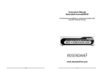
PROFESSIONNAL PORTABLE
MULTITRACK RECORDER
SONOSAX
MINIR82
User Manual
Audio Equipment Manufacturer
SONOSAX SAS SA
Ch. De la Naz 38
1052 Le Mont s/ Lausanne
SWITZERLAND
MINIR82- User Manual / Septembre 2006 / pb
Tel :
Fax :
+41 21 651 01 01
+41 21 651 01 09
Web :
Email :
www.sonosax.ch
[email protected]
Page 1 of 30
QUICK START
Powering
External PSU: use only the optional SONOSAX power supply .
Batteries:
use only rechargeable NiMh batteries, standard dry cell batteries can not power
the MINIR82. Insert batteries as shown on the picture below.
External DC supply : The MINIR82 can also be supplied from an external suitable DC source
from 5 to 9 V. A 2 meter long cable with the DC plug is available, part nr V980010. For use with
high capacity 12V battery, a 9V to 18V DC/DC converter will soon be available.
Power On
Press simultaneously the UP and DOWN key to turn on the MINIR82.
MINIR82- User Manual / Septembre 2006 / pb
Page 2 of 30
CF Card
Before using a new CompactFlash card with the MINIR82, you must format it FAT32 on your PC
Some cards are faster than others and you must use fast CF cards only. Please contact your
nearest SONOSAX distributor for further information.
Firmware up-date
Firmware file name: Vxxxxx.BIN
•
•
•
•
•
•
•
•
•
•
•
•
(e.g. V20431.bin => version 2.0.431)
For safety, save all your files .
Connect the MINIR82 to the USB2 port of your PC, two drives named [CONFIG] and
[AUDIO] will be automatically mounted.
For safety, back up all your files on your PC, including your "User Settings" stored on the
folder named "SETTING" in the [CONFIG] drive.
Use Windows Explorer to copy the firmware file to the root directory of the [AUDIO] drive
of the MINIR82 ( e.g: G:\V20431.BIN )
Alternatively you can also copy the firmware file to root directory of the CF card.
Remove the USB2 cable and turn Off the MINIR82 as displayed on the MINIR82 screen.
Turn On the MINIR82, go to the "MENU" page, select "Browse Files". The firmware file
appears on the screen at the bottom of the list of files. If not, use the "Down" Key to
scroll down and highlight the firmware file.
If the firmware was copied ot the CF card, select […] then [COMPACTFLASH]
Highlight the Firmware (ex. V20431.BIN) using the "Down" key and press "SELECT".
The screen displays the current version « Running Version : (e.g. 2.0.422) » and the new
version to be installed « File Version : (e.g. 2.0.431) ». Press "OK" to confirm the up-date
or "CANCEL" to abort.
Once the up-date begins, a progression bar is displayed. Please wait until the up date is
competed and then press "OK".
Due to compatibility issues between firmware versions, it is advised to reformat both
[CONFIG] and [AUDIO] drives as well as the CF card. Use the Quick Format option to
save time.
Restore your "SETTING" folder to the [CONFIG] drive
Pyramix
Before using your PYRAMIX NATIVE, please register to www.merging.com/pyramix/native
MINIR82- User Manual / Septembre 2006 / pb
Page 3 of 30
User Interface
Display 10 lines x 17 characters
Left Channel LED
UP Key
Right Channel LED
Red LED
RIGHT Key
LEFT Key
DOWN Key
Green LED
Light sensor
MINIR82- User Manual / Septembre 2006 / pb
Page 4 of 30
Turning ON the MINIR82
Turning ON the MINIR82 is done by pressing simultaneously the UP and DOWN Keys.
A boot up screen is displayed for approx. 2 seconds and shows following information's:
•
•
•
•
The remaining free available space on the hard disk and on the CompactFlash card
A power indication of either the batteries or the external PSU by means of a bar graph
Date and Time
The running firmware version
Note : it can take a while until the remaining available free space is displayed
MINIR82- User Manual / Septembre 2006 / pb
Page 5 of 30
Principle of operation
Status
The MINIR82 status is shown by means of the green or red "status" led's and the screen display
Following status are possible:
•
•
•
•
•
RECORD READY
the Red LED is flashing, the MINIR82 is ready to start recording
RECORDING
the Red LED lights On steady, confirming that a recording is in progress.
PLAYING
the Green LED lights On steady, a take is being played
PLAY PAUSE
the Green LED flashes, indicating that the Take being played is actually Paused.
PLAY STOP.
a Take is loaded ready to be played, no LED light on nor flashes
Clipping LEDs
The "Left Channel" and "Right Channel" Led's shows two particular status that are either:
•
•
Limiters : either the Left or the Right LED lights On independently when the Microphone
Input signal reaches a level of 2,5dB before clipping, thus activating the Limiter.
Clipping: the Input signal is too high on the microphone A/D Converter, both Left and
Right LED's light On together
On screen Display and Keys
The main working page ( Tracks Monitoring ) displays the 8 Peak Meters.
The meter range starts at –72dBfs and goes up to 0dBfs in 1dB steps from –72dB up to –24dB
and in 0,5dB steps from –23,5dB up to 0dB.
A configurable reference (-9, -12, -18 et –20 dB) can be displayed ( see configuration menu )
The bottom line of the display shows the functions of the Keys. Conventionaly, the UP and
DOWN keys are used to change the parameters, the Left key is used to "Select" and the Right
Key to "Cancel".
A single Arrow symbol denotes that an action is achieved by briefly pushing the key.
A double Arrow symbol means that the key must be pushed longer to validate the action.
MINIR82- User Manual / Septembre 2006 / pb
Page 6 of 30
Architecture - Audio path
The MINIR82 offers12 physical Inputs channels, up to 8 of these audio channels can be used at
the same time. These 8 channels are configured per pair :
• 1, 2 : either AES or Microphone input
• 3, 4 : either AES or Line input
• 5, 6 : AES
• 7, 8 : AES
The routing Matrix allows to route and mix any of the input channels onto any of the 10 tracks.
Then first 8 tracks are dedicated for the hard disk (HD) and the 2 additional tracks for the
CompactFlash card (CF).
For Monitoring purpose, you can configure and listen any combination of these 10 tracks.
However, the display shows only the 8 hard disk tracks Peakmeters
Channel 1
Channel 2
Mix config
Channel 3
Channel 4
Mixer
Channel 5
Channel 6
Channel 7
Channel 8
1
2
3
4
Tracks
5 6 7
8
9 10
Modulometers values
Left
Right
Modulometers
Monitor
Monitor config
Bits per sample
File encoding
(WAVE, dithering)
Pre-record buffer
FAT32 / ATA layer
HDD
MINIR82- User Manual / Septembre 2006 / pb
CF
Page 7 of 30
Track Monitoring
The TRACK MONITORING is the main screen displayed by the MINIR82. The numbering is
always displayed and is related to the HD tracks. The number of each active track in use is
shown in reverse video.
Battery power indicator
Timecode
(HH :MM :SS)
TAKE Nr
Track Peak meter
Peak meters reference
Function of the keys
Note: the Peak meter reference is adjustable in the "Configuration" menu.
Actions or function of the keys are described as below:
Key
LEFT
RIGHT
UP
DOWN, while Record Ready
DOWN, while Recording
DOWN, in Stop
DOWN, while Playing
DOWN, in Pause
LEFT & RIGHT
Short pressure
Reduce the headphone
volume by 1dB
Increase the headphone
volume by 1dB
Enter Solo Monitoring page
Start Recording
Add an index **
Start Playing
Pauses at current position
Play from current position
Lock/Unlock keypad
Long pressure
Keep pressing to continuously
reduce the volume down to min
Keep pressing to continuously
increase the volume up to max
Enter contextual Menu page
Stop Recording
Stop playing
Switch to Stop mode
Pressing the LEFT or the RIGHT key display a temporary screen showing the headphone level
by means of a bargraph. The headphone level is adjustable in 1dB step from –30dB to +18dB.
MINIR82- User Manual / Septembre 2006 / pb
Page 8 of 30
Contextual Menu
The Contextual Menu allows a quick navigation between the different pages and configurations
menu of the MINIR82. The Contextual Menu can only be accessed from the Track Monitoring Page
Key
LEFT
RIGHT
UP
DOWN
Short pressure
Long pressure
Confirm the selection
Return from the menu to the
Tracks Monitoring page
Scroll the selection upward
Scroll the selection doqnward
The possible choices in the Contextual Menu depend of the current "Status" of MINIR82 as
described below:
While in Status "Recording"
• Monitoring
• Unit Status
While in Status "Playing"
• Last Takes
• Monitoring
• Unit Status
• Delete Take
While in Status "Record Ready"
• Monitoring
• Last Takes
• Unit Status
• Setup
• Browse Files
• Switch Off
While in Status "Stop"
• Last Takes
• Exit Player Mode
• Monitoring
• Unit Status
• Browse Files
• Delete Take
• Switch Off
MINIR82- User Manual / Septembre 2006 / pb
Page 9 of 30
Solo Monitoring
The "Solo Monitoring" page is accessed from the "Track Monitoring" page by briefly pressing the
UP Key. It allows to Monitor in mono any individual track or a specific pair of track.
The displayed page is visually identical to the "Track Monitoring" page except that a round dot
replaces the selected track being soloed.
The track selection sequence is as follow: 1, 2, 1+2, 3, 4, 3+4, 5, 6, 5+6, 7, 8, 7+8.
The UP key moves the selection upward, the DOWN key moves the selection downward
The SoloMonitoring is only possible with active ( armed ) tracks
Key
LEFT
RIGHT
UP
DOWN
LEFT & RIGHT
Short pressure
Reduce the headphone
volume by 1dB
Increase the headphone
volume by 1dB
Select the previous track or
pair of tracks
Select the next track track or
pair of tracks
Lock/Unlock keypad
Long pressure
Keep pressing to continuously
reduce the volume down to min
Keep pressing to continuously
increase the volume up to max
Retour au tracks monitoring
The example above shows a configuration of 4 active ( or armed ) tracks :1, 2, 3, 5
the track 1 being currently selected for Solo Monitoring.
In this particular case, the selection sequence for the Solo is: 1, 2, 1+2, 3, 5
MINIR82- User Manual / Septembre 2006 / pb
Page 10 of 30
Monitoring
This Monitoring page allows you to mix the 10 tracks of the MINIR82 for it's headphone output.
The configuration of the monitoring is done by means of a specific menu as shown below
The Monitoring is always configured per pair of tracks ( 10 tracks = 5 pairs of tracks )
The table below shows the available choices and their respective monitoring results on the stereo
headphone output for the pair of tracks 1 and 2.
Key
--MONO
STEREO
REV STEREO
MS
MONO L
MONO R
Short pressure
Muted
1+2
1
2
1+2
1+2
Muted
Long pressure
Muted
1+2
2
1
1–2
Muted
1+2
The table below describes the key functions
Key
LEFT
RIGHT
UP
DOWN
Short pressure
Change the Monitoring type
Save the modifications and
return to the previous Menu
Move the selector upward
Move the selector downward
Long pressure
Note: If a pair of track is not activated ( or not armed ) the only possible value is "No Monitoring"
MINIR82- User Manual / Septembre 2006 / pb
Page 11 of 30
Last Takes
This screen allows you to rapidly access a list of the Last Takes having been recorded in a reverse
order, the very last Take is at the top od the list.
The first line displays the date ( YY/MM/DD ) and the time of the selected Take
La première ligne donne la date (format YY/MM/DD) et l’heure de la prise sélectionnée.
Each TAKE is presented with following forms:
XX YYYYYYYY-ZZZ
Where
XX is the media source where the TAKE is stored ( HD or CF )
YYYYYYYY is the scene name and ZZZ is the TAKE number.
By selecting a TAKE, the MINIR82 loads it to it's memory. Depending of the media source and the
TAKE length, it may take a certain time before the TAKE becomes ready for the Playback.
.
Key
LEFT
RIGHT
UP
DOWN
MINIR82- User Manual / Septembre 2006 / pb
Short pressure
Load the selected TAKE
Back to the Contextual Menu
Move the selector upward
Move the selector downward
Long pressure
Page 12 of 30
Unit Status
This page dispays the major parameters of the MINIR82
.
Project Name
Battery Power
Scene Name
Loaded User Setting
Sampling informations
Take Number
Time Code
HD & CF free memory
space
The displayed parameters are :
•
•
Line 1 :
Line 3 :
•
•
Line 4 :
Line 5 :
•
Line 6 :
•
•
Line 7 :
Line 8 :
Battery power indicator ( fuel gauge )
Project Name – Loaded User Setting (displayed only if the configuration has
been loaded and not been modified )
Scene Name - Take number
Sampling rate (24/16) / Sampling frequency, synchronisation source
(INTERNAL, AES, WCK IN)
or video stream type : PAL/25, NTSC/29.97, 1080/23.97, 1080/24, 1080/25,
1080/29.97, 1080/30, 720p/24, 720p/25, 720p/29.97, 720p/30, 720p/50,
720p/59.94, 720p/60, 295M-P/25 or Video Err.
Time Code value and its format : Int (Internal), 24, 25, 29 (29.97Non Drop),
29D (29.97 Drop), 30 (30 Non Drop) or 30D (30 Drop). If the Time Code can not
be readed (unknown format) the Time Code value becomes: -- :-- :-Remaining available free space on the Hard Disk
Remaining available free space on the CompactFlash card
Key
LEFT
RIGHT
UP
DOWN
MINIR82- User Manual / Septembre 2006 / pb
Short pressure
Long pressure
Back to the Contextual Menu
Page 13 of 30
Setup ( Configuration Menus )
The Menus of Configuration are posted by calling the Contextual Menu and by selecting "Setup" in
the list. The menus are classified in headings (rubrics), and grouped in a logical order. The
navigation from heading to heading is done by the keys UP and DOWN. On the line of the screen,
a scrool bar indicates the position in the list of choice of the headings.
The LEFT key (SELECT) makes it possible to enter the sub-heading and the RIGHT key (EXIT,
BACK) makes it possible to return to the preceding screen.
The tree structure of the menus imposes the use of sub-menus until arriving at the parameter
which one wishes to modify.
The menu without parameter posts a heading by screen. It
makes it possible to classify the various parameters.
The menu with parameter corresponds at the end of the tree
structure of the menu, it thus presents the current value of the
parameter which can be modified
While pressing on SELECT in a menu with parameter, the user
can change its value. One distinguishes several manners of
carrying out this change.
The menu with a list presents the possible choices of a
parameter. The selection is posted in reverse video.
The menu of text-editing.
The text to be modified is presented between brackets which
shows the limits of the text size (max. 8 characters). Two arrows
show the selected character.
The keys react as follows: UP and DOWN allow to modify the
selected character. Keep pressing to scroll the characters.
LEFT and RIGHT keys move the cursor to select the character.
A long pressure on LEFT saves the text and returns to the
preceding menu. A long pressure on RIGHT cancels the edition
and returns to the preceding menu
MINIR82- User Manual / Septembre 2006 / pb
Page 14 of 30
Tree structure of the menus
The menus in gray represent the menus where the parameters are visible.
Level 1
ROUTING
SETTINGS
RECORD
SETTINGS
Level 2
ROUTING
MIXING LEVEL
PROJECT NAME
SCENE NAME
FILE FORMAT
SAMPLING
SETTINGS
Level 3
Specific Menu ( cross matrix )
SAMPLING FREQUENCY
SAMPLING UP/DOWN
SAMPLING RATE
PRE-RECORD TIME
PRE-INDEX DELAY
SYNC MODE
INPUT SOURCE
INPUT
SETTINGS
MIC LOW FREQ
CUT
IN 1-2
IN 3-4
IN 1
IN 2
LINE IN LEVEL
TIMECODE
SETTINGS
Changeable values
NONE, ATT1.5, ATT3, ATT6
Text editor
Text editor
MONO, STEREO
44.1, 48, 88.2, 96, 176.4, 192 kHz
Nominal, UP o/oo, DOWN o/oo
24 bits, 16 bits dither, 16 bits
1, 2, 5, 10, 20 sec
0, 1, 2, 3, 5 sec
OFF, WDCKIN, VIDEO IN
AES, MIC
AES, LINE
OFF, ON
OFF, ON
+15, +6, 0, -10 dBu
EXTERNAL JAM SYNC, EXTERNAL
NO JAM, INTERNAL
AUTODETECT, 24, 25,
29.97 NON-DROP, 29.97 DROP,
30 NON-DROP, 30 DROP
FREE RUN, RECORD RUN
INPUT SOURCE
INPUT FORMAT
RUNNING MODE
SET MANUAL
SET FROM TIME
NONE, -9, -12, 18, -20 dB
MODULOMET
REFERENCE
ERS
SETTINGS
NONE, 5 sec, 10 sec, 2 min,
INFINITE
HOLD TIME
USER
SETTINGS
Specific Menu
DATE
TIME
MISC
SYSTEM INFO
USER INTERFACE
CHECK
FACTORY
SETTINGS
Specific Menu to set up Date
Specific Menu to set up Time
Post the revision software and
others infos
Allows to test the screen, LEDs
and the Keys
Re-initialized all current
parameters
Explanation of each menu is given in the following page.
MINIR82- User Manual / Septembre 2006 / pb
Page 15 of 30
SETUP > ROUTING SETTINGS > ROUTING
The configuration of the routing is carried out by means of a specific menu describes below:
Tracks
Input
Channels
Routing Matrix
The round dot sets or remove a connection between the Inputs (Channels Input) and the Tracks.
In the figure above, a routing 1: 1 is established between the Inputs and the hard disk Tracks.
The table below summarizes the actions of the keys:
Key
LEFT
Short pressure
Move the selection to the Left
RIGHT
Move the selection to the Right
UP
DOWN
Move the selection upward
Move the selection downward
Notes :
Long pressure
Confirm the routing modification
(active/inactive)
Save the configuration and returns to
the preceding menu
in this menu, it is not possible to leave without saving the configuration.
The unsed input channels (no dot on the crossing) are automatically desactivated.
SETUP > ROUTING SETTINGS > MIXING LEVEL
When two or more inputs are routed and mixed on the same Track, the MIXING LEVEL menu
allows to apply an attenuation in dB, on a per channel basis, in order to avoid digital overload.
The MINIR82 will then automatically calculate the total attenuation according to the number of
input channels to be mixed together. Four possible choices are offerred:
• NONE
no attenuation is applied
• ATT1.5
to be used when sources have no phase coincidence
• ATT3
to be used when sources do have a phase coincidence ( stereo pair )
• ATT6
to be used when sources are in phase
The table below summarizes the attenuations carried out:
Number of Input channels
assigned to the same Track
1
2
3
4
5
6
7
8
MINIR82- User Manual / Septembre 2006 / pb
NONE
[dB]
0
0
0
0
0
0
0
0
ATT1.5
[dB]
0
1.8
2.5
3.3
3.3
4.1
4.1
5
ATT3
[dB]
0
3.3
5
6
7.2
7.2
8.5
8.5
ATT6
[dB]
0
6
10.1
12
14.5
14.5
18.1
18.1
Page 16 of 30
SETUP > RECORD SETTINGS > PROJECT NAME
This menu allows to specify the Project Name. This one is used with several aims:
• Name of the directory where the Takes will be stored.
• Archivage of the Project Name in each WAVE file (sub-chunk BWF and iXML)
The format of the Project Name is as follows:
• 8 characters maximum
• alphanumerics characters and space only (A..Z, 0..9, ‘ ‘)
SETUP > RECORD SETTINGS > SCENE NAME
This menu allows to specify the Scene Name. This one is used with several aims:
• Partially Name the directory where the audio files of the Takes will be stored
• Archivage of the Scene Name in each WAVE file (sub-chunk BWF and iXML)
The format of the Scene Name is as follows:
• 8 characters maximum
• alphanumerics characters and space only (A..Z, 0..9, ‘ ‘)
SETUP > RECORD SETTINGS > FILE FORMAT
The File format offers two choices :
• MONO
• STEREO
If MONO is selected, each track is recorded in a separated file, in mono.
If STEREO is selected, the system records a pair of tracks in a stereo file. The pairs are always
1+2, 3+4, 5+6 and 7+8.
If the configuration of the Routing sets incomplete pairs of tracks (for example tracks 1, 3, 4 and 7)
each insulated track is recorded in a stereo file and uses a half of the file size.
SETUP > RECORD SETTINGS > SAMPLING SETTINGS > SAMPLING FREQUENCY
This menu allows defines the sampling frequency. Choices are : 44.1, 48, 88.2, 96, 176.4,192 kHz.
The selected value is not used when the MINIR82 uses the AES Inputs. In this case the MINIR82
will lock on the incoming AES sample frequency.
SETUP > RECORD SETTINGS > SAMPLING SETTINGS > SAMPLING UP / DOWN
This menu makes it possible to define the possible correction for the NTSC world. The possible
values are NOMINAL (use of the nominal sampling value), UP ‰ (positive correction of one per
thousand) and DOWN ‰ (negative correction of one per thousand).
SETUP > RECORD SETTINGS > SAMPLING SETTINGS > SAMPLING RATE
This menu sets the number of bits per sample (sampling rate ) stored in WAVE files. The possible
values are 24 bits, 16 bits dither and 16 bits. The dithering is of triangular type.
MINIR82- User Manual / Septembre 2006 / pb
Page 17 of 30
SETUP > RECORD SETTINGS > PRE-RECORD TIME
The Pre-Record time can be set from de 1 second and up to 20 seconds. The definite value may
not always be possible because of the physical limitation of the built-in memory and the selected
configuration. The pre-record time depends on the following factors:
• Number of Tracks being used
• Sampling frequency
• Sample Rate and Pull UP/ Pull DOWN correction
When the pre-record time required is not possible, the MINIR82 will work on "best effort" to provide
with the possible maximum. The table below shows the max. values of the pre-record time [sec.]:
16 bits
fs
44100
48000
88200
96000
176400
192000
24 bits
fs
44100
48000
88200
96000
176400
192000
1
20.0
20.0
20.0
20.0
20.0
20.0
1
20.0
20.0
20.0
20.0
20.0
20.0
2
20.0
20.0
20.0
20.0
20.0
19.1
2
20.0
20.0
20.0
20.0
13.9
12.7
3
20.0
20.0
20.0
20.0
13.9
12.7
Tracks count
4
5
6
7
8
9
10
20.0 20.0 20.0 20.0 20.0 18.5 16.6
20.0 20.0 20.0 20.0 19.1 17.0 15.3
20.0 16.6 13.9 11.9 10.4 9.2 8.3
19.1 15.3 12.7 10.9 9.6 8.5 7.6
10.4 8.3 6.9 5.9 5.2 4.6 4.2
9.6 7.6 6.4 5.5 4.8 4.2 3.8
3
20.0
20.0
18.5
17.0
9.2
8.5
Tracks count
4
5
6
7
8
9
10
20.0 20.0 18.5 15.9 13.9 12.3 11.1
20.0 20.0 17.0 14.6 12.7 11.3 10.2
13.9 11.1 9.2 7.9 6.9 6.2 5.5
12.7 10.2 8.5 7.3 6.4 5.7 5.1
6.9 5.5 4.6 4.0 3.5 3.1 2.8
6.4 5.1 4.2 3.6 3.2 2.8 2.5
In these tables, the UP/DOWN correction is not taken into account (negligible).
SETUP > RECORD SETTINGS > PRE-INDEX DELAY
The pre-index delay is the time of anticipation when adding an index. It proposes the following
values: 0, 1, 2, 4 and 5 seconds. The graph below shows to what corresponds this time:
TAKE 27
TAKE 28
• Adding an index
(by pressing the DOWN key
while in REC mode)
PRE-INDEX DELAY
t
The pre-delay index is not absolute, the software making doing his best to cut the Take to nearest
of desired time (best effort).
However, no data is lost during the addition of the index !
MINIR82- User Manual / Septembre 2006 / pb
Page 18 of 30
SETUP > RECORD SETTINGS > SYNC MODE
This menu allows to define the mode of synchronization of the MINIR82. By synchronization, one
means the use of an external clock on a given signal. This section does not treat the use of
timecode.
The mode of synchronization used by the MINIR82 is posted in the menu "Unit Status".
Different the mode are explained below with the various parameters and their validity.
OFF
Internal Generator
The MINIR82 has an very stable internal clock generator, capable to generate all the audio
frequencies (44.1, 48, 88.2, 96, 176.4 and 192 Khz) within 1ppm. This generator is used only when
no other clock is available.
Sampling frequency : active
Sampling up/down :
active
Sampling rate:
active
Synchronisation on AES input
The MINIR82 is locked automatically on the incoming AES clock of the channels 5-6
Sampling frequency : inactive
Sampling up/down :
inactive
Sampling rate:
active
WCK IN
Synchronisation WCK IN
WCK IN must be set in the menu SYNC MODE to use the Word Clock connected on the SYNC IN.
This mode is not used if a valid AES signal is present.
Sampling frequency : inactiv
Sampling up/down :
inactiv
Sampling rate:
active
VIDEO IN
Synchronisation Video IN
VIDEO IN must be set in the menu SYNC MODE to use the Clock of a Video feed
This mode is not used if a valid AES signal is present
Sampling frequency : active
Sampling up/down :
inactive
Sampling rate:
active
MINIR82- User Manual / Septembre 2006 / pb
Page 19 of 30
SETUP > INPUT SETTINGS > INPUT SOURCE
This menu one can select which Input source must be applied to the channels 1-2 and 3-4.
For channels 1-2, the possible sources are:
• AES
• MIC
For channels 3-4, the possible sources are:
• AES
• LINE
SETUP > INPUT SETTINGS > MIC LOW FREQ CUT
When channels 1-2 are configured as MIC, a low-pass filter can be activated for each channel
individually by this menu,.
SETUP > INPUT SETTINGS > LINE IN LEVEL
When channels 3-4 are configured as LINE, the input level can be adapted to properly match with
the A/D Converter, thus the selected value matches the 0dBfs of the A/D.
It presents the following choices:
• +15 dBu
• + 6 dBu
•
0 dBu
• -10 dBu
MINIR82- User Manual / Septembre 2006 / pb
Page 20 of 30
SETUP > TIMECODE SETTINGS > INPUT SOURCE
The Time Code source is configurable with following choices:
• External Jam Sync
• External No Jam
• Internal
SETUP > TIMECODE SETTINGS > INPUT FORMAT
The MINIR82 is able to automatically detect the Time Code format present on the T.C. input
However, in order to be sure to use the good format, it is possible to specify it. In this case, the
detection of a format different from that specified will give an alarm. The formats suggested are:
• Autodetect
• 24
• 25
• 29.97 Non Drop
• 29.97 Drop
• 30 Non Drop
• 30 Drop
SETUP > TIMECODE SETTINGS > RUNNING MODE
Two possible choices:
• FREE RUN
• RECORD RUN
In FREE RUN mode, the Time Code is absolute and linear. It runs continuously and never stops.
In RECORD RUN mode, the Time Code is running only while Recording.
SETUP > TIMECODE SETTINGS > SET MANUAL
This menu makes it possible to adjust the Time Code manually.
SETUP > TIMECODE SETTINGS > SET FROM TIME
This menu will adjust the Time Code exactly at the time of the real time clock of the MINIR82.
MINIR82- User Manual / Septembre 2006 / pb
Page 21 of 30
SETUP > MODULOMETERS SETTINGS > REFERENCE
To set and display a level reference on the screen of the modulometers (Track Monitoring).
The choices of references are:
• NONE
• - 9 dB
• -12 dB
• -18 dB
• -20 dB
SETUP > MODULOMETERS SETTINGS > HOLD TIME
The function “Hold Time” detect the absolute peak level and keep it posted for:
• NONE
• 3 secondes
• 10 secondes
• 2 minutes
• INFINITE
MINIR82- User Manual / Septembre 2006 / pb
Page 22 of 30
SETUP > USER SETTINGS
The “User Settings” makes it possible to save, load or up date a complete configuration setting to/
from an ASCII file.
CREATE NEW…
Allows to create a new file of configuration based on the running ( active ) configuration of the
MINIR82.
RECALL SELECTED
Allows to load a configuration file. Caution: this operation will crush the current configuration!
DELETE SELECTED
Delete the seleted configuration file.
OVERWRITE SELECTED
Overwrite an existing configuration by the current configuration of the MINIR82
MINIR82- User Manual / Septembre 2006 / pb
Page 23 of 30
SETUP > MISC > DATE
To set the Date of the internal Real Time Clock (format is DD.MM.YYYY).
SETUP > MISC > TIME
To set the Time of the internal Real Time Clock (format HH:MM:SS).
SETUP > MISC > SYSTEM INFO
This menu shows all the hardware and software characteristics of the MINIR82: firmware version
of the DSP, the firmware version of the display microcontroler (PIC), battery voltage and hardware
version of the AES receivers.
SETUP > MISC > USER INTERFACE CHECK
This menu allows to check the LCD display, the LEDs and the keys.
SETUP > MISC > FACTORY SETTINGS
This menu allows to re-initialyze the MINIR82 in its basic configuration (factory default ).
Caution: this operation crushes the currently loaded configuration. It does not modify the audio
data on the discs nor the user settings.
MINIR82- User Manual / Septembre 2006 / pb
Page 24 of 30
Browse Files
The file browser uses a specific menu :
The directory [..] allows to go back one step in the tree structure.
The LEFT key (SELECT) action depends of the context :
•
•
•
•
If it is about a Take directory, the selected Take is loaded.
If it is about a directory (e.g. a Project), its contents is posted.
If it is about a firmware release, the update starts after a request for confirmation
In all the other cases, an error message is posted (see below).
Selecting [..] at the root level of a disk ( e.g. the root of the HD ) allows to swap to the other disk (
e.g. the root of the CF). This is achieved by means of a selection menu.
When a file is not recognized or cannot be interpreted, the following message is posted:
MINIR82- User Manual / Septembre 2006 / pb
Page 25 of 30
Organisation of the disks
The hard disk is always splitted in 2 partitions:
• Partition [CONFIG] , size = about 50 to 100Mb, format : FAT32
• Partition [AUDIO] , size = all remaining space, format FAT32
The aim of having two partitions is that it makes it possible to format the audio partition without
losing the configurations ( User Settings).
The software of the MINIR82 does not support “hot plugin” of the CompactFlash card (CF).
If the action is carried out, a warning message will be posted and in some cases it might be
necessary to reboot the MINIR82.
The "Config" partition is structured as explained below:
[CONFIG]
• CONFIG.DAT
Binary file, it contains all informations of the current configuration. This file is loaded while
powering on the MINIR82, it is overwriten with the current (active) configuration and
settings while powering off. This file is not modifiable by the user.
• [SETTINGS]
Directory containing the files of the saved configurations (saved User Settings) which can
be reloaded on the "User Setting" menu. These files can be modified and even created with
an ASCII editor such as the Windows Notepad.
The "Audio" partition is structured as follow:
[AUDIO]
• [PROJECT NAME]
Project directory (8 characters) the directory name is that of the "Projet Name".
o [SCENE_NAME.TAKE_NUMBER]
the directory name is that of the "Scene Name" (8 characters) directly followed by a
dot then by the TAKE number (3 digit).
This directory contains the BWF audio files and a configuration file (CONFIG.INI).
This file is formatted in ASCII and represents the configuration of the MINIR82 at
the time of the shot. It is used to reconfigure the MINIR82 for the playback and is
not intended to be modified.
MINIR82- User Manual / Septembre 2006 / pb
Page 26 of 30
USB
The MINIR82 is equipped with a USB 2.0 port. The MINIR82 authorizes connection to a computer
for file transfer ( PC or Mac ) and, when connected, it will automatically activate the USB port while
the MINIR82 is in one of the following menu:
• Tracks monitoring
• Solo monitoring
• Unit Status
The MINIR82 posts the following screen when the USB connection is active:
When disconnecting the USB cable, the MINIR82 forces the user to extinguish the apparatus
It is then necessary to press the LEFT key to switch off the MINIR82.
MINIR82- User Manual / Septembre 2006 / pb
Page 27 of 30
Alarms
Certain situations require that the user have to be alerted on a particular point. When this occurs,
the MINIR82 intermittently posts a warning concerning the detected problem and a beep tone is
heard in the headphone. The beep tone remain only until the user presses on any key.
One distinguishes 5 types of alarms, whose causes are explained below:
Alarm SYNC occurs when one of the following conditions is checked:
• One or more Tracks is assigned from an AES input, but no AES signal is present
• No AES input being assigned, the MINIR82 is set to WCK IN but no WordClock signal is
present or the WordClock signal is invalid.
• No AES input being assigned, the MINIR82 is set to VIDEO IN but no Video signal is
present or the Video signal is invalid.
Alarm TC occurs when one of the following conditions is checked:
• The TimeCode is set in Free Run - External Jam Sync, a TC signal is present but the
format selected in the MINIR82 does not correspond to the detected format.
• The TimeCode is set in Free Run - External No Jam, but no TC signal is present
• The TimeCode is set in Free Run - External No Jam, a TC signal is present but the format
selected in the MINIR82 does not correspond to the detected format.
Alarm HD or CF occurs when one of the following conditions is checked :
•
•
•
The hard disk does not comprise the two awaited partitions.
It remains less than 100Mb of free space in a disk
The recording in progress written in files whose size approaches the possible maximum
size of 4Gb. Alarm engages when there remains less than 100Mb.
The power Alarm occurs when the supplied voltage is soon too weak to maintain the MINIR82 in
function.
MINIR82- User Manual / Septembre 2006 / pb
Page 28 of 30
Treatment of the errors
This section treats of the possible errors and problems that may occur while using the MINIR82.
Power issue
When the supply voltage becomes too weak, the MINIR82 proceeds to a safe shut down. If a
recording is in progress, it is stopped properly.
Note: please remember not to use dry cell batteries but NiMh rechargeable batteries instead
Insufficient disk space
If the remaining free space in a disk is too small, the recording in progress is stopped. When two
discs are used (HD + CF), the recording is stopped if one of the two discs does not have enough
free space.
Maximum file size
The FAT32 file system limits the size of the files to 4 GB. If the recording in progress reaches this
limit, the MINIR82 adds an index and continues to record in the new Take (without loss of data).
Disk too fragmented
During the power-up, the MINIR82 checks the fragmentation of the discs. In case of severe
fragmentation the recording is not allowed, an error message informs the user of the problem. It is
then advisable to re-format the disk (while having saved the existing data before !!!!).
Real Time Clock ( RTC)
During the power-up, the MINIR82 checks if the Date and the Time of the system are coherent. If it
is not the case, a menu forces the user to define them. While setting the date, an error message
can occur if the date format is not valid.
Note:
the MINIR82 does not have an internal back-up battery to keep the RTC running
ininterrupted when NiMh batteries are removed or external DC supply is not
present. However it maintain Date and Time for a period of approx 2 hours. It is
therefore advised to leave well charged batteries in their compartment.
MINIR82- User Manual / Septembre 2006 / pb
Page 29 of 30
Recommendations
The architecture of the MINIR82 and its operating software brings to some recommendations :
Copy of Takes
It is strongly advised to copy (transfert) the Takes carried out by the MINIR82 to the hard disk of a
computer. The opposite is however not possible: the MINIR82 will not be able to read an audio file
copied to its disk from a computer.
Defragmentation
Never attempt to defragment the discs used by the MINIR82. For performance reasons, Recording
the Takes is carried out by interlacing the various files which make it up. These files must remain
interlaced so that the playback of the Takes remains possible. In the event of too severe
fragmentation of a disc, it should be re-formatted (the fast formatting is enough).
Note: please remember back-up your file before reformatting a disk !!
Deleting files
Deleting a files is possible, but it must always be carried out by Take (suppression of the Take
directory only). The suppression of a project is completely possible too.
Formating
The MINIR82 works only with the FAT32 filing system. The setting of the clusters size can be left in
the default value.
Use of the hard disk
The hard disk of the MINIR82 is accessible via the USB interface. In a general way, the hard disk
must be used for the audio recording. However, it is completely possible for the user to to lay out of
the disk space with an aim other than that of the audio recording. It is on the other hand important
that this use does not penalize the fragmentation of the disc.
MINIR82- User Manual / Septembre 2006 / pb
Page 30 of 30
MICROPHONES CONNECTIONS MINIR82
R
6
+ IN
8
+ 48V
1
PH
5
- IN
4
GND
6
+ IN
7
+ 3.3V
5
- IN
4
GND
6
+ IN
7
+ 3.3V
5
- IN
4
GND
6
+ IN
8
+ 48V
7
+ 3.3V
5
- IN
4
GND
2
+ IN L
6
+ IN R
7
+ 3.3V
3
- IN L
5
- IN R
4
GND
Microphone 48V Phantom
Electret 3 wires
Electret 2wires
~ 2.2kohms
R=
Microphone Schoeps active cable
Microphone Sanken COS 22
MINIR82
7
1
6
8
3
5
2
4
MIC/LINE IN LEFT CONNECTOR
1) PH
2) - 3) - 4) GROUND
5) IN- (LEFT)
6) IN + (LEFT)
7) + 3.3V
8) + 48V
1
7
6
5
4
2
3
8
MIC/LINE IN RIGHT CONNECTOR
1) PH
2) IN + (LEFT)
3) IN - (LEFT)
4) GROUND
5) IN - (RIGHT)
6) IN + (RIGHT)
7) + 3.3V
8) + 48V