1
File Name:
MEITRACK VT310 User Guide
Creator:
Project:
VT310
Sub Project:
Revision:
User Guide
V7.4
Creation Date:
Update Date:
Page:
Confidential:
Cavana Cheung
2010-08-26
2012-08-02
- 14 - of 30
External Documentation
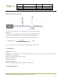
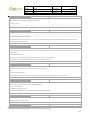
9.2 Detecting Lock Status of Car’s Door or Trunk (Car Boot).
Power supply
Lock Controller
White
lock
Input 1 or Input 2 or Input 3
unlock
Lock Switch
When the lock is opened, there will be a negative trigger to Input 1 or Input 2 or Input 3.
After this, an SMS alarm will be sent to
the authorized phone number, or a GPRS alarm will be sent to the server (please refer to the GPRS Command 0x9999 in GPRS
Communication Protocol).
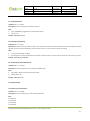
9.3 Connecting with Switch Sensors
The SMS alarm will be sent to the authorized phone number.
Input 1 or Input 2 or Input 3
White
Switch Sensor
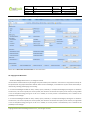
9.4 Ignition Detection
Input 4 or Input 5 (positive triggering) can be used for ignition detection. The detection alarm will be sent to the server via GPRS.
Please refer to <GPRS Communication Protocol> Alarm Command 0x9999 for more information.
Power for ignition
Input 4 or Input 5
Ignition Switch
Battery
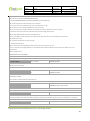
9.5 Analog Input (AD1 and AD2)
Input voltage should be 0~6V. Please refer to GPRS Communication Protocol for more information for AD1 and AD2 data.
For example:
094506.000,A,2232.5412,N,11404.6919,E,0.00,,290709,,*12|1.7|110|0000|00AA,0267
AD1 is 0x00AA and AD2 is 0x0267.
Voltage Formula: Input Voltage=(AD*6)/1024
0x00AA=>170(decimal)=>(170*6)/1024=0.99609375V(voltage)
Copyright © 2012 Shenzhen Meiligao Electronics Co., Ltd. All rights reserved.
- 14 -