1
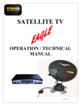
SATELLITE TV OPERATION / TECHNICAL MANUAL 31 March 2014 The Eagle Manual 2 The Eagle Manual I ndex Warning ....................... 4 Mount Definitions ........................ 5 Controller Views ....................... 6 Configuration and Software Versions ....................... 8 Menus and Operations ....................... 9 Connector Wiring Diagram ....................... 11 Raising the ODU Using a 12 VDC Source ....................... 11 SWM DirecTV Block Diagram ....................... 12 Foot Print and Clearances ....................... 13 Returning Parts to the Factory ....................... 14 3 The Eagle Manual WARNING Make all electrical and coax connections from the controller to the mount and LNB's BEFORE applying power to, or connecting the satellite receiver to the controller. Note: When the controller is turned OFF it continues to pass voltage from the receiver to the LNB if the receiver remains connected to 110 AC power. Shorting the coax at any time during installation may cause damage to either the Controller or the DiSEqC Switch (if installed). Failure to follow this procedure can result in voiding of warranty replacement, not to mention time spent trying to troubleshoot a system that does not perform. REMEMBER 90% of all problems are a result of incorrect CONNECTIVITY or CONFIGURATION. 4 The Eagle Manual M ount definitions A system consists of several components MOUNT (ODU) Reflector/Parabola Note: Your LNB may vary from the one pictured depending upon your system configuration. LNB Arm Assembly Mount or Azimuth Base Mounting Feet Connector Weather Cover Clam Shell Items included with the system and are not shown. 1 ea LNB Landing Plate 15' Control Cable, 25' 1 ea Connector, green, 12 pin 1 ea Power Supply, 12 VDC 7 amp 1 ea RE-1000 User Guide 1 ea EAGLE Controller 5 The Eagle Manual C ontroller Views FRONT VIEW Definitions and Usage CONTROLLER (IDU) FIND Directs the system to "FIND" Satellites. Navigates through the menu and selects a particular function. STOW Directs the system to "STOW" the mount and prepare it for travel Navigates through the menu and selects a particular function. LCD Display Displays the actions of the system. USB Programming Port Used for upgrading firmware. POWER Will turn controller ON and OFF. Navigates through the Menu options. LED REC indicates the receiver coax is attached to the controller. VDC indicates power is being supplied to the controller. 6 The Eagle Manual REAR VIEW Definitions and Usage CONTROLLER (IDU) To REC To LNB CONNECTIONS POWER 12 VDC 7 amp (power supply provided). CONTROL CABLE CONNECTION: Termination of the 12 wires of the control cable to the controller takes place here. TO SATELLITE RECEIVER This is a coax pass-through connection to your satellite receiver (Satellite IN). It is optional except for DirecTV SWM. TO ODU LNB: This is a coax connection to the Antenna's LNB. The connection is made at the base of the mount to any one of 4 coax cables that run through the mount and are secured to the LNB. If you have DirecTV SWM, then the cable attached to the DiSEqC switch must be routed directly to the controller uninterrupted then to the connection marked "TO LNB". (see configuration to determine which coax at the base of the mount goes to the controller). Label on the bottom of the controller 7 The Eagle Manual C onfigurations and Software Version Each of the Program Providers will require different software EAGLE -1 EAGLE -2 EAGLE -3 EAGLE -4 SHAW Direct = DirecTV SWM = Dish Network = Bell Express = 107.3, 107.3, 111.1 Satellites 99, 101, 103 Satellites 110, 119, 129 Satellites 81, 92 Satellites (For Canadian Use Only) (For Canadian Use Only) TO CONFIGURE Configuration of your system is done through software. There is a specific version of software for each Program Provider. Go to www.rfmogul.com to download (to your USB Flash Drive) the appropriate software for your program provider. Place the USB flash drive into the USB Program Port on the front of the controller and turn the power ON. The controller will display downloading status and transfer the Program Provider file into memory. This process will take approximately 8-10 seconds. SOFTWARE VERSION UPGRADES Why should you think about downloading new software or changing configurations? 1. To take advantage of new innovative features offered by the latest revision of software. 2. If you have called your installer and he/she has recommended it. 3. If you read the History of the new software and you determine that you could benefit from its features. 8 The Eagle Manual M enu Options Menus and Operation Your controller is menu driven. By selecting a particular menu you can perform many functions besides just "SEARCHING for satellite". TO SEARCH Press the Power button o Displayed will be the.... System configuration (software configuration) EAGLE 1 SHAW (Triple Satellite xKu LNB) EAGLE 2 DIRECTV (SWM 3 LNB) EAGLE 3 DISH NETWORK (Triple Satellite 1000.2 LNB) EAGLE 4 BELL TV (Triple Satellite 1000.2 LNB) Version of software i.e. 14.02.07 Options are accessed by pressing "SELECT" or POWER button again to enter the menu options. To navigate through the options press either the SEARCH (UP arrow) or STOW (DOWN arrow) TO ENTER MENU OPTIONS Press the Power button again after turning ON the power to enter the "menu" portion of your system....... o Press the Up and Down arrows to help you navigate through the menu. Once the portion of the menu that you want is displayed, press SELECT (POWER button) to "select" that option.... 1: shutdown - Selecting this option will turn OFF your controller 2: search - Selecting this option will direct the mount to search for your specific satellite that is specified in your system configuration 3: stow - Selecting this option will cause the mount to return to its travel position 4: move azimuth - Selecting this option and pressing and holding the appropriate button will manually move your mount in azimuth (Up arrow CLOCKWISE, Down arrow COUNTERCLOCKWISE 5: move elevation - Selecting this option and pressing and holding the appropriate button will manually move your mount in elevation (Up arrow UP, Down arrow DOWN 9 The Eagle Manual 6: move skew - Selecting this option and pressing and holding the appropriate button will manually move your dish in skew (Up arrow right side DOWN, Down arrow left side DOWN 7: test dish - Selecting this option will move the dish in all axis for one complete cycle 8: temperature - Selecting this options will display current operating temperature of its operating environment. 9: exit - Selecting this option will take you back to main menu NOTE: There is an "OVER TEMPERATURE" condition that will be displayed at the beginning of the SEARCH function if the operating environment is in excess of 136°F. It will not prevent the SEARCH routine but will warn of potential damaging heat conditions for the equipment within that operating environment. AFTER LOCKING ONTO THE PROPER SATELLITE: The controller will remain ON for a few minutes and then automatically turn OFF. AFTER STOWING: The controller will automatically turn OFF. Updating and Maintaining Software The software can be maintained by use of a USB Flash Drive. Call RF Mogul for the software for your application. Make sure that it is placed in the "root directory" and that no other .hex file is in that directory. Insert your flash drive into your EAGLE RE-1 controller. Turn power ON Wait for the progress bar that will indicate that the software is being successfully loaded (usually 8 seconds). Remove the flash drive and press SEARCH to implement acquisition. 10 The Eagle Manual C onnector Wiring Diagram Wiring the 12 Pin Controller Connector RAISING THE ODU USING A 12 VDC SOURCE TO RAISE THE MOUNT WITH A BATTERY Pin Used Color How Used Where 1 = 2 = 3 = 4 = 5 = 6 = 7 = 8 = 9 = 10 = 11 = 12 = BLACK BROWN RED ORANGE YELLOW GREEN BLUE VIOLET GRAY WHITE PINK TAN Motor Motor Motor Motor Motor Motor Count Count Count -Azimuth +Azimuth -Elevation +Elevation - Skew +Skew Azimuth Elevation Skew Touch the following wires from the control cable directly to a drill battery or any 12 VDC source and it will result in movement of the ODU. To reverse the direction, reverse the wires to your battery. ELEVATION Red and Orange will raise and lower the mount AZIMUTH Black and Brown will rotate the dish SKEW Yellow and Green will tilt dish. Wire Color Wire Function BLACK BROWN Ground 12 Volts DC GPS TXD RED ORANGE YELLOW GREEN 11 +AZ -AZ +EL -EL - SKEW +SKEW The Eagle Manual SWM Block Diagram INSET Note: The SWM LNB has 8 channels available. Each DVR takes 2 channels (one coax). A non DVR uses one channel (one coax). You may use any combination of receivers until you use up all 8 channels. Example: A HR34 uses 5 channels leaving 3 channels available. IDU Receiver line Note: See bottom of IDU for wiring instructions. 4 Port splitter shown. 8 Port splitter is available 110 Volts AC DIRECTV SWM INSTALLATION 12 The Eagle Manual F ootprint and Clearances 39 Inches 8 1/2 Inches 13 1/2 Inches Distance for installing LNB Landing Plate Rotational clearance from center rotation point is 18 inches when dish is elevated and rotating. This is a safety zone. 36 Inches CONTROLLER 10" Wide 6" Deep 2" high 13 The Eagle Manual R eturning Parts to the Factory Parts returned to the factory must contain a Return Material Authorization (RMA) which will be provided by the RF Mogul Technical Support Department at the time of troubleshooting. This will ensure proper accountability of returned equipment or parts. Make sure that the following information is contained on your shipment. RF Mogul Attn: Product Evaluation Department RMA # _______________ 3604 South Via Terra South Salt Lake City, UT 84115 You must include your Return Address and Telephone Number. Failure to comply may result in you being billed for a non-returned part. We appreciate your business. If you need to contact us please see the information below. RF Mogul 3604 South Via Terra South Salt Lake City, UT 84115 Tele 801-895-3308 Fax 801-478-5850 www.rfmogul.com [email protected] [email protected] 14