1
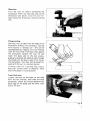
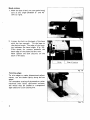
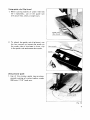
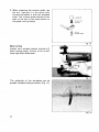
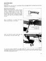
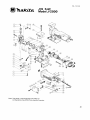
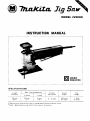
MODEL JVZOOO
INSTRUCTION MANUAL
DOUBLE
INSULATION
SPEC1 FICATIONS
Max. cutting capacities
of stroke
2 0 mm
(3/4")
1
in wood
50"
(2")
1
6 mm
(114")
1
0-3'400
1
263 m m
(10-3/8")
* Manufacturer reserves the right t o change specifications without notice
Note: Specifications may differ from country to country.
1.6 k g
(3.5 Ibs)
IMPORTANT
I SAFETY INSTRUCTIONS
(For All T o o l s )
TY PRECAUTIONS SHOULD ALWAYS BE FOLLOWED TO
REDLCE THE RISK OF FIRE, ELECTRIC SHOCK, AND PERSONAL INJURY, INCLUDING THE FOLLOWING:
READ ALL INSTRUCTIONS.
1.
2.
WORK AREA CLEAN. Cluttered areas and benches invite injuries.
IDER WORK AREA ENVIRONMENT. Don't use power tools in damp
3.
CHILDREN AWAY. All visitors should be kept away from work area.
let visitors contact tool or extension cord.
4.
5.
6.
TOOL. Don't force small tool or attachment t o do the job of a
7.
PROPERLY. Don't wear loose clothing or jewelry. They can be caught
ing parts. Rubber gloves and non-skid footwear are recommended
8.
SAFETY GLASSES. Also use face or dust mask if cutting operation is
9.
IO.
11.
12.
13.
2
ptacle. Keep cord from heat, oil, and sharp edges.
URE WORK. Use clamps or a vise t o hold work. It's safer than using
hand and it frees both hands t o operate tool.
N ' T OVERREACH. Keep proper footing and balance at all times.
INTAIN TOOLS WITH CARE. Keep tools sharp and clean for better and
14.
F IMOVE ADJUSTING KEYS AND WRENCHES. Form habit of checking t o
20. F
!e that keys and adjusting wrenches are removed from tool before turning
on.
JOlD UNINTENTIONAL STARTING. Don't carry plugged-in tool with finger
I switch. Be sure switch is OFF when plugging in.
UTDOOR USE EXTENSION CORDS. When tool is used outdoors, use only
:tension cords intended for use outdoors and so marked.
TAY ALERT. Watch what you are doing, use common sense. Don't operate
01 when you are tired.
HECK DAMAGED PARTS. Before further use of the tool, a guard or other
irt that is damaged should be carefully checked t o determine that it will
ierate properly and perform its intended function. Check for alignment of
oving parts, binding of moving parts, breakage of parts, mounting, and any
her conditions that may affect its operation. A guard or other part that
damaged should be properly repaired or replaced by an authorized serve center unless otherwise indicated elsewhere in this instruction manual.
w e defective switches replaced by authorized service center. Don't use
01 if switch does not turn it on and off.
UARD AGAINST ELECTRIC SHOCK. Prevent body contact with grounded
irfaces. For example; pipes, radiators, ranges, refrigerator enclosures.
!PLACEMENT PARTS. When servicing, use only identical replacement parts.
vo LT
outle
namc
for t k
the tl
voltas
,GE WARNING: Before connecting the tool t o a power source (receptacle,
etc.) be sure the voltage supplied is the same as that specified on the
)late of the tool. A power source with voltage gr.eater than that specified
! tool can result in SERIOUS INJURY t o the user - as well as damage t o
01. If in doubt, DO NOT PLUG IN THE TOOL. Using a power source with
e less than the nameplate rating is harmful t o the motor.
E
I'
15. L
C
16.
(
E
17. $
t
18.
(
F
C
r
c
I
I'
t
t
19.
(
I
3
ADDITIONAL SAFETY RULES
1. Avoid cutting nails. Inspect for and remove all nails from the workpiece before operation.
2. Don't cut hollow pipe.
3. Do not cut oversize workpiece.
4. Check for the proper clearance beneath the workpiece before cutting so that
the blade will not strike the floor, workbench, etc.
5. Hold the tool firmly.
6. Check the blade is n o t contacting the workpiece before the s w i t c h is turned
on.
7. Keep hands away f r o m moving parts.
8. When cutting through walls, floors or wherever "live" electrical wires may
be encountered, DO NOT TOUCH ANY METAL PARTS OF THE TOOL!
Hold the tool only by the plastic handle t o prevent electric shock if you cut
through a "live"
wire.
9. Do n o t leave the tool running. Operate the tool only w h e n hand-held.
IO. Always s w i t c h off and wait
for the blade t o come t o a complete stop before
removing the blade f r o m the workpiece.
11. Do n o t t o u c h the blade or the workpiece immediately after operation; they
may be extremely h o t and could burn your skin.
SAVE THESE INSTRUCTIONS.
4
HOW TO USE
Installing jig saw blade
Use the hex wrench to loosen the hex
socket head bolt which holds the blade.
m
I
Loosen
Fig 1
With the blade teeth facing forward, insert
the blade into the blade holder as far as
it will go.
Make sure that the back edge of the blade
fits into the roller and tighten the hex
socket head bolt securely with the hex
wrench.
-
Fia 2
NOTE :
The larger hole of the blade can be seen as
shown in Fig. 3 even after blade installation.
r
r4
Fig.
:
S
Switch action
To start the tool, simply squeeze the
switch lever. Release the lever to stop.
Tool speed (0 to 3,400 RPM) i s increased
by increasing pressure on the lever.
CAUTION :
Before plugging in the tool, always check
to see that the paddle switch actuates properly and returns to the "OFF" position
when released.
Switch lever (Paddle
~
__
wifed
I
Fig. 4
Straight line or orbital cutting action
Conventional jig saws cut with a straight
line action, that is, the blade moves only
up and down in a straight line. ,Your saw
also cuts in this manner but, for softer
materials, an orbital cutting action can be
selected. Soft materials, like wood and
plastic permit deep penetration of individual saw teeth. The orbital action thrusts
the blade forward on the cutting stroke
and greatly increases cutting speed over
conventional jig saws. Harder materials like
metal should be cut using the straight line
cutting action or a very low orbital setting.
To select straight line or orbital cutting,
adjust the number on the saw.
I
Fig.
Position 0 - Thick metal. Clean cuts in wood, plastics, vinyl chloride, etc.
Position I
- Thin metal, aluminum,
hard wood. Curved line cutting.
Position I1 - Wood, plastics, vinyl chloride, etc. Hi-speed aluminum, metal cutting.
Curved line cutting.
Position I11 - Hi-speed wood cutting.
6
Operation
Turn the tool on before contacting the
workpiece. Then rest the base flat on the
workpiece and gently move the tool forward along the previously marked cutting
line.
Fig. 6
Plunge cutting
Starting a cut a t other than the edge of the
workpiece without first drilling a starting
hole requires a “plunge cut”. This can be
accomplished by tipping the tool forward
until the front end of the base rests against
the workpiece. Switch the tool on and
lower the back end of the tool slowly,
gradually allowing the balde to saw through
the wood until the base is able to sit flat on
the workpiece. You may then proceed forward with the cut in a normal manner.
I f using a drill for a starting hole, bore a
hole over 12 mm (1/2”) in diameter. Then
insert the blade in i t and proceed.
I
L
I
Fig.
’
Front flush cuts
Loosen the bolt on the back of the base
with the hex wrench, then slide the base
backwards. Check the contact between the
back edge of the blade and the roller, then
secure the bolt.
Fig. 8
7
Bevel cutting
1 . With the base tilted, you can make bevel
cuts a t any angle between 0" and 45"
(left to right).
I
Fig. 9
2. Loosen the bolt on the back of the base
with the hex wrench. Tilt the base to
the desired angle. The edge of the housing indicates the bevel angle. (Fig. I O ) .
Then check for contact between the
back edge of the blade and the roler.
Now tighten the bolt securely on the
back of the base.
I
Roller
1
Edge of housing
Fig. I (
Finishing edges
To trim edges or make dimensional adjust.
ments, run the blade lightly along the cut
edges.
For smoother cutting of plywoods or other
materials with easily splintered surfaces,
the wood may be coated or transparent
tape used over your cutting line.
1
7
Fig. 1 1
8
Using guide rule (Rip fence)
1. When cutting widths of under 150 mm
(6") repeatedly, use of the guide rule
will assure fast, clean, straight cuts.
2. To attach the guide rule (rip fence), use
the hex wrench to loosen the screw on
the under side of the base in front, slip
in the guide rule and secure the screw.
Fig. 13
Using circular guide
1. Use of the circular guide insures clean,
smooth cutting of circles (radius; under
200 mm; 7-7/8") and arcs.
Fig. 14
9
2. When attaching the circular guide, use
the pin, inserting it in the center hole
(arrow) and secure it with the threaded
knob. The circular guide attaches to the
base of the tool in the same manner as
the guide rule (rip fence).
Pic for
circular gulde
Fig. 15
Metal cutting
Always use a suitable coolant (cutting oil)
when cutting metal. Failure to do so will
cause significant blade wear.
Fig. 16
The underside of the workpiece can be
greased instead of using a coolant. (Fig. 17).
Fig. 17
10
MAINTENANCE
CAUTION :
Always be sure that the tool is switched off and unplugged before attempting to perform
inspection or maintenance.
Replacing carbon brushes
Remove and check the carbon brushes
regularly. Replace when they wear down
to about 4.5 mm (3/16") or less. Keep
the brushes clean and free to slip in the
holders. Both brushes should be changed
a t the same time, Use only Makita carbon
brushes.
,...- -..
U
4.5"
(3/16")
Fig. 18
Use a screwdriver to remove the brush
holder cap as shown in the figure.
Fig. 19
Take out the worn brush, insert the new
one and secure the brush holder cap.
I
I
Fig. 20
To maintain product SAFETY and RELIABILITY, repairs, any other maintenance or
adjustment should be performed by Makita Authorized or Factory Service Center, always
using Makita replacement parts.
11
ACCESSORIES
CAUTION
These accessories or attachments are recommended for use with your Makita tool specified in this
manual The use of any other accessortes or attachments might present a risk of injury to persons The
accessories or attachments should be used only in the proper and intended manner.
0
Jig saw blade (packed 10 each in handy vinyl pouch)
scro
0
Guide rule (Rip fence)
Part No. 164113-2
0
Circular guide assembly
Part No. 123030-5
12
0
cu
ing
Hex wrench 3
Part No. 783201-2
hc.-18-'84
@"
EN
JIG SAW
Model JV2000
Note: The switch, noise suppressor and other part
configurations may differ from country to country
13
Dec -18
MODEL J V 2 0 0 0
AtD
$s0ED
DESCRIPTION
DESCRIPTION
MACHINE
~
1
2
3
4
5
1
6
1
1
1
6
7
1
8
9
10
11
12
13
14
15
16
17
18
19
20
21
22
23
24
25
1
1
1
1
2
1
4
1
1
1
1
1
2
1
1
1
1
1
26
1
I
27
28
29
30
31
32
1
1
2
1
1
1
Note The SwItch
14
Pan Head Screw M 5 x 8 IWifh Warherl
Compresslo" s p m g 4
Sleel Ball 4
PI" 4
Pin 4
Roller
33
34
35
36
37
38
1
1
1
2
1
1
2
2
1
1
1
1
1
1
2
RelalMl
39
s p o n g e 1 2 21
Blade Clamp
Hex Socket Head Boll M 4 x 1 0
G~~~ noUPlng c o v e r
Pan Head Screw M4x35 IWith Washer]
Fiber Washer 8
Felt
Slider
Ball Bearing 805
Holder
Pan Head Screw M4xB IWifh Washer]
40
41
42
43
44
45
46
47
48
49
50
51
Pan Head Screw M6x55 IWith Washerl
52
I
GW
53
54
1
1
5)
1
58
59
60
61
82
1
1
1
1
2
2
1
2
1
2
Plate
Needle Bearing 407
Bush 4
Gear
Flat Washer 28
c a m Plate
Flat Washer 8
G W nourlng
Rubber Pin 4
Ball Bearing 608LB
Fan 58
ARMATURE ASSEMBLY
lWith Items 30
341
and other part s p e ~ i f i ~ a t ~ omay
n s differ f r o m country
63
64
65
66
61
1
1
1
2
- to country
insulation Washer
Ball Bearing 627LB
FIELD ASSEMBLY
Hex 80'1 M4x55 IWilh Warherl
Lever 3 0
Steel Ball 3 5
Flat Washer 6
Stop Ring E 4
Needle Bearing 810
Flat Washer 6
S T O PRing E 6
Hex Nur M 5
Base
Hex Socket Head Ball M5x10
Stop Ring E 3
Hex Socket Head Boll M4x25
Spring Washer 4
Clamp Plate
Rivet 0 5
Name Plate
Motor Housing
Cord Guard
Stop Ring E - 3
Swifch Lever
P," 4
Cord
Switch
Carbon Brush
Brush Holder C a p
Strain Relief
Pan Head Screw M 4 x 1 8 (With Washer)
Switch Cover
Pan Head Screw M 4 x 3 0 IWith Washerl
84 US
MAKITA LIMITED ONE YEAR WARRANTY
Warranty Policy
Every Makita tool is thoroughly inspected and tested before leaving the factory. It is warranted to
be free of defects from workmanship and materials for the period of ONE YEAR from the date of
original purchase. Should any trouble develop during this one-year period, return the COMPLETE
tool, freight prepaid, to one of Makita’s Factory or Authorized Service Centers. If inspection shows
the trouble is caused by defective workmanship or material, Makita will repair (or at our option,
replace) without charge.
This Warranty does not apply where:
repairs have been made or attemvted by others:
repairs are required because of normal wear and tear:
The tool has been abused, misused or improperly maintained;
alterations have been made to the tool.
IN NO EVENT SHALL MAKITA BE LIABLE FOR ANY INDIRECT, INCIDENTAL OR CONSEQUENTIAL DAMAGES FROM THE SALE OR USE OF THE PRODUCT. THIS DISCLAIMER
APPLIES BOTH DURING AND AFTER THE TERM OF THIS WARRANTY.
MAKITA DISCLAIMS LIABILITY FOR ANY IMPLIED WARRANTIES, INCLUDING IMPLIED
WARRANTIES OF “MERCHANTABILITY” AND “FITNESS FOR A SPECIFIC PURPOSE,”
AFTER THE ONE-YEAR TERM OF THIS WARRANTY.
This Warranty gives you specific legal rights, and you may also have other rights which vary from
state to state. Some states do not allow the exclusion or limitation of incidental or consequential
damages, so the above limitation or exclusion may not apply to you. Some states do not allow
limitation on how long an implied warranty lasts, so the above limitation may not apply to you.
maKita€&c&u Mknka,Ltd.
=
11-8.3-chome, Sumiyoshi-cho. Anjo, Aichi 446, Japan
883285 - 063A
PRINTED IN JAPAN
1985-1 1-N