1
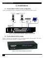
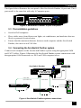
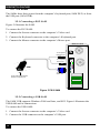
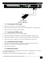
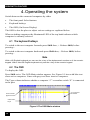
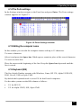
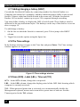
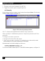
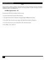
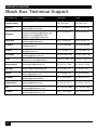
JUNE 2004
KV1108A
KV1116A
ServSwitch Panther
CUSTOMER
SUPPORT
INFORMATION
Order toll-free in the U.S.: Call 877-877-BBOX (outside U.S. call 724-746-5500)
FREE technical support, 24 hours a day, 7 days a week: Call 724-746-5500 or fax 724-746-0746
Mail address: Black Box Corporation, 1000 Park Drive, Lawrence, PA 15055-1018
Web site: www.blackbox.com • E-mail: [email protected]
SERVSWITCH TM FAMILY
Welcome to the ServSwitchTM Family!
Thank you for purchasing a BLACK BOX® ServSwitch Panther! We appreciate your
business, and we think you’ll appreciate the many ways that your new ServSwitch
Panther will save you money, time, and effort.
That’s because our ServSwitch family is all about breaking away from the traditional,
expensive model of computer management. You know, the one-size-fits-all-even-if-itdoesn’t model that says, “One computer gets one user station, no more, no less.” Why
not a single user station (monitor, keyboard, and mouse) for multiple computers – even
computers of different platforms? Why not a pair of user stations, each of which can
control multiple computers? Why not multiple user stations for the same computer?
With our ServSwitch products, there’s no reason why not. We carry a broad line of
robust solutions for all these applications. Do you have just two PC’s, and need an
economical alternative to keeping two monitors, keyboards and mice on your desk? Or
do you need to share dozens of computers, including a mix of IBM®PC, RS/6000®,
Apple® Macintosh®, Sun Microsystems®, and SGI TM compatibles among multiple
users with different access levels? Does your switch have to sit solidly on a work-table
and use regular everyday cables? Or does it have to be mounted in an equipment rack
and use convenient many-to-one cables? No matter how large or small your set-up is,
no matter how simple or how complex, we are confident we have a ServSwitch system
that’s just right for you.
The ServSwitch TM family from BLACK BOX, the one-stop answer for all your KVM
switching needs!
This manual will tell you about your new ServSwitch Panther, including how to install,
operate, and troubleshoot it.
For an introduction to the ServSwitch Panther, see chapter 1.
The ServSwitch Panther product codes covered in this manual are:
KV1108A
KV1116A
This manual also includes information about the Server Access Modules:
KV1120A
KV1121A
1
FCC INFORMATION
FEDERAL COMMUNICATIONS COMMISSION
AND
CANADIAN DEPARTMENT OF COMMUNICATIONS
RADIO FREQUENCY INTERFERENCE STATEMENTS
This equipment generates, uses, and can radiate radio frequency energy and if not
installed and used properly, that is, in strict accordance with the manufacturer’s
instructions, may cause interference to radio communication. It has been tested and
found to comply with the limits for a Class A computing device in accordance with the
specifications in Subpart B of Part 15 of FCC rules, which are designed to provide
reasonable protection against such interference when the equipment is operated in a
commercial environment. Operation of this equipment in a residential area is likely to
cause interference, in which case the user at his own expense will be required to take
whatever measures may be necessary to correct the interference.
Changes or modifications not expressly approved by the party responsible for
compliance could void the user’s authority to operate the equipment.
This digital apparatus does not exceed the Class A limits for radio noise emission from
digital apparatus set out in the Radio Interference Regulation of the Canadian
Department of Communications.
Le présent appareil numérique n’émet pas de bruits radioélectriques dépassant les
limites applicables aux appareils numériques de la classe A prescrites dans le
Règlement sur le brouillage radioélectrique publié par le ministère des Communications
du Canada.
Trademarks
All trademarks and registered trademarks are the property of their respective owners.
22
NOM STATEMENT
Normas Oficiales Mexicanas (NOM)
Electrical Safety Statement
INSTRUCCIONES DE SEGURIDAD
1. Todas las instrucciones de seguridad y operación deberán ser leídas antes de que el
aparato eléctrico sea operado.
2. Las instrucciones de seguridad y operación deberán ser guardadas para referencia futura.
3. Todas las advertencias en el aparato eléctrico y en sus instrucciones de operación deben
ser respetadas.
4. Todas las instrucciones de operación y uso deben ser seguidas.
5. El aparato eléctrico no deberá ser usado cerca del agua—por ejemplo, cerca de la tina de
baño, lavabo, sótano mojado o cerca de una alberca, etc.
6. El aparato eléctrico debe ser usado únicamente con carritos o pedestales que sean
recomendados por el fabricante.
7. El aparato eléctrico debe ser montado a la pared o al techo sólo como sea recomendado
por el fabricante.
8. Servicio—El usuario no debe intentar dar servicio al equipo eléctrico más allá a lo
descrito en las instrucciones de operación. Todo otro servicio deberá ser referido a
personal de servicio calificado.
9. El aparato eléctrico debe ser situado de tal manera que su posición no interfiera su uso.
La colocación del aparato eléctrico sobre una cama, sofá, alfombra o superficie similar
puede bloquea la ventilación, no se debe colocar en libreros o gabinetes que impidan el
flujo de aire por los orificios de ventilación.
10. El equipo eléctrico deber ser situado fuera del alcance de fuentes de calor como
radiadores, registros de calor, estufas u otros aparatos (incluyendo amplificadores) que
producen calor.
11. El aparato eléctrico deberá ser connectado a una fuente de poder sólo del tipo descrito en
el instructivo de operación, o como se indique en el aparato.
3
SERVSWITCH PANTHER
12. Precaución debe ser tomada de tal manera que la tierra fisica y la polarización del equipo
no sea eliminada.
13. Los cables de la fuente de poder deben ser guiados de tal manera que no sean pisados ni
pellizcados por objetos colocados sobre o contra ellos, poniendo particular atención a los
contactos y receptáculos donde salen del aparato.
14. El equipo eléctrico debe ser limpiado únicamente de acuerdo a las recomendaciones del
fabricante.
15. En caso de existir, una antena externa deberá ser localizada lejos de las lineas de energia.
16. El cable de corriente deberá ser desconectado del cuando el equipo no sea usado por un
largo periodo de tiempo.
17. Cuidado debe ser tomado de tal manera que objectos liquidos no sean derramados sobre
la cubierta u orificios de ventilación.
18. Servicio por personal calificado deberá ser provisto cuando:
A: El cable de poder o el contacto ha sido dañado; u
B: Objectos han caído o líquido ha sido derramado dentro del aparato; o
C: El aparato ha sido expuesto a la lluvia; o
D: El aparato parece no operar normalmente o muestra un cambio en su desempeño; o
E: El aparato ha sido tirado o su cubierta ha sido dañada.
44
COMPLIANCE STATEMENTS
EUROPEAN UNION DECLARATION OF CONFORMITY
This equipment has been tested and found to comply with the limits for a Class A
computing device in accordance with the specifications in the European standard
EN55022. These limits are designed to provide reasonable protection against harmful
interference. This equipment generates, uses, and can radiate radio frequency energy
and, if not installed and used in accordance with the instructions, may cause harmful
interference to radio or television reception.
However, there is no guarantee that interference will not occur in a particular
installation. If this equipment does cause interference to radio and television reception,
which can be determined by turning the equipment off and on, you can correct the
interference by one or more of the following measures:
1.
Reorient or relocate the receiving antenna.
2.
Increase the separation between the equipment and receiver.
3.
Connect the equipment into an outlet on a circuit different from that to which
the receiver is connected.
4.
Consult the supplier or an experienced radio/TV technician for help.
Shielded cables must be used with this equipment to maintain compliance with radio
frequency energy emission regulations and ensure a suitably high level of immunity to
electromagnetic disturbances. This equipment has also been found to comply with
European standard EN 55024.
Japanese Compliance Statement
CB TEST CERTIFICATE
This product was tested and found to be in conformity with:
IEC 60950 (2001) for Interference by Information Technology Equipment aimed at
preventing radio interference in such residential areas. When used near a radio or TV
receiver, it may become the cause of radio interference. Read instructions for correct
handling.
5
SERVSWITCH PANTHER
Contents
Chapter.................................................................................................................. page
1.
Introduction...........................................................................................8
1.1
1.2
2.
Complete package................................................................................9
2.1
3.
Features .........................................................................................................8
Compatibility.................................................................................................8
Additional items needed ................................................................................9
Installation...........................................................................................10
3.1
The ServSwitch Panther system configuration ............................................10
3.2
The ServSwitch Panther models..................................................................10
3.3
Pre-installation guidelines ...........................................................................11
3.4
Connecting the ServSwitch Panther system.................................................11
3.5
The SAMs ...................................................................................................12
3.5.1 Connecting a PS/2 SAM.............................................................................12
3.5.2 Connecting a USB SAM ............................................................................12
3.6
Connecting the CAT5 cables.......................................................................13
3.7
Connecting the KVM console .....................................................................13
3.8
Connecting the power supply ......................................................................13
3.9
Resetting the Switch ....................................................................................13
3.10 Avoiding general rack mounting problems..................................................14
3.10.1 Elevated operating ambient temperature ..................................................14
3.10.2 Reduced airflow .......................................................................................14
3.10.3 Mechanical loading ..................................................................................14
3.10.4 Circuit overloading...................................................................................14
3.11 Rack mounting the ServSwitch Panther.......................................................14
3.12 Cascading ServSwitch Panthers...................................................................15
4.
Operating the system.........................................................................16
4.1
The keyboard hotkeys..................................................................................16
4.2
The OSD......................................................................................................16
4.3
Navigating the OSD ....................................................................................17
4.4
Selecting a computer ...................................................................................17
4.5
The OSD settings (F2).................................................................................17
4.6
The General settings ....................................................................................17
4.7
Security........................................................................................................18
4.7.1 Administrator (Status A) ............................................................................18
4.7.2 Supervisor (Status S) ..................................................................................18
4.7.3 User (Status U) ...........................................................................................18
4.7.4 Activating password protection .................................................................. 19
66
CONTENTS
4.8
4.9
4.10
4.11
4.12
4.13
4.14
4.15
4.16
4.17
4.18
4.19
4.20
4.21
4.22
4.23
4.24
4.25
5.
Troubleshooting .................................................................................27
5.1
5.2
6.
Changing the OSD hotkey ...........................................................................19
Autoskip ......................................................................................................19
Serial port ....................................................................................................20
Changing the Keyboard language................................................................20
Editing the Switch name ..............................................................................20
F7 Defaults ..................................................................................................20
The Ports settings ........................................................................................21
Editing the computer name..........................................................................21
Keyboard (KB)............................................................................................21
Adding/changing a hotkey (HKEY) ............................................................22
The Time settings ........................................................................................22
Scan (SCN) - Label (LBL) - Time out (T/O)...............................................22
Users............................................................................................................23
Security........................................................................................................24
The OSD HELP window – F1 .....................................................................24
Scanning computers– F4 .............................................................................25
Tuning – F5 .................................................................................................25
Moving the label – F6 .................................................................................26
Calling Black Box .......................................................................................27
Shipping and Packaging ..............................................................................27
Upgrading the firmware .....................................................................28
6.1
System requirements for the ServSwitch Panther Update software .............28
6.2
Connect the ServSwitch Panther System .....................................................28
6.3
Installing the software .................................................................................28
6.4
Connecting the Flash Upgrade cable ...........................................................28
6.5
Starting and configuring the ServSwitch Panther Update............................29
6.6
Verifying the version numbers ....................................................................30
6.6.1 The OSD version number...........................................................................31
6.6.2 The ServSwitch Panther version number....................................................31
6.6.3 Verifying the SAM version number ...........................................................31
6.7
Updating the firmware.................................................................................31
6.7.1 Communication Error.................................................................................32
6.7.2 Electricity failure........................................................................................33
6.8
Reset............................................................................................................33
6.8.1 Resetting the Switch or SAM units.............................................................33
7.
Technical specifications ....................................................................34
7
SERVSWITCH PANTHER
1. Introduction
Access and control multiple multi-platform computers from one Keyboard Video
Mouse (KVM) console with the ServSwitch Panther system. The ServSwitch Panther
comes in 8 and 16 port models. Connect up to 8 computers to the 8 port model, and up
to 16 to the 16 port model.
1.1 Features
•
Hot-Swap - disconnect and reconnect computers without rebooting
•
Scan-mode operation with variable time interval
•
1U Rack mountable
•
Operate the system using an On Screen Display (OSD) or front panel push buttons
or keyboard hotkeys
•
Create multi-level cascade arrangements. For example by cascading the
ServSwitch Panther 16 Port model, connect up to up to 256 computers in the
system
•
The computers can be placed up to 33ft/10m from the ServSwitch Panther
•
Multi-platform — supports PS/2 and USB computers/servers
1.2 Compatibility
The ServSwitch Panther is compatible with:
•
PS/2 and USB computers/servers
•
VGA, SVGA, or XGA monitors
•
DOS, Windows (3X, 9X, 2000, NT4, ME, XP, 2003 Server) LINUX, UNIX,
QNX, SGI, FreeBSD, BeOS, Open VMS, Novell 3.12-6, Alpha UNIX and HP UX
88
2. Complete package
2. Complete package
The ServSwitch Panther system comes with:
•
ServSwitch Panther 8 Port (KV1108A) or 16 port (KV1116A)
•
Flash Upgrade cable (KV11UP)
•
USA and European power cords
•
Rack mount kit for the ServSwitch Panther (KV11RM)
2.1 Additional items needed
1 Server Access Module (SAM) and CAT5 cabling per attached server or switch.
The SAMs come in two different models:
•
SAM PS/2 (KV1120A) for PS/2 servers
•
SAM USB (KV1121A) for USB servers
9
SERVSWITCH PANTHER
3. Installation
3.1 The ServSwitch Panther system configuration
Figure 1 illustrates the basic configuration of the ServSwitch Panther system.
Computer 1
Computer 16
SAM
SAM
ServSwitch
Panther
COMPUTER
9
10
11
12
13
14
15
16
1
2
3
4
5
6
7
8
POWER
100-250 VAC 50/60 Hz
Figure 1 The ServSwitch Panther system configuration
3.2 The ServSwitch Panther models
Figure 2 illustrates the front panel of the ServSwitch Panther 16 port model. The 8 port
model is the same but with only 8 columns of LEDs.
Figure 2 ServSwitch Panther front panel
10
10
3. Installation
The figure below illustrates the rear panel of the ServSwitch Panther 16 port unit. The 8
port model is the same but with only 8 Computer ports.
COMPUTER
9
10
11
12
13
14
15
16
1
2
3
4
5
6
7
8
POWER
100-250 VAC 50/60 Hz
Figure 3 ServSwitch Panther 16 port rear panel
3.3 Pre-installation guidelines
•
Switch off all computers
•
Place cables away from fluorescent lights, air conditioners, and machines that are
likely to generate electrical noise
•
Ensure that the maximum distance between each computer and the ServSwitch
Panther, does not exceed 33ft/10m
3.4 Connecting the ServSwitch Panther system
Connect each computer to the ServSwitch Panther system using the appropriate SAM
and CAT5 cables. Figure 4 illustrates the ServSwitch Panther system connections with
the appropriate SAM connected to a PS/2 and USB computer/server.
P110
SD
ServSwitch Panther
COMPUTER
9
10
11
12
13
14
15
16
1
2
3
4
5
6
7
8
POWER
100-250 VAC 50/60 Hz
CAT5 cable
Up to 10M / 33ft
CAT5 cables
NetServer tc2100
Mouse
Keybd
100T
Parallel
Serial A
Video
Serial B
PS/2 SAM
SCSI
PCI 33Mx32b
PCI 33Mx32b
PCI 33Mx32b
PCI 33Mx32b
USB SAM
USB SAM
Figure 4 ServSwitch Panther system connections
11
SERVSWITCH PANTHER
3.5 The SAMs
The SAMs draw their power from the computer’s keyboard port (SAM PS/2) or from
the USB port (SAM USB).
3.5.1 Connecting a PS/2 SAM
Figure 5 illustrates the SAM.
To connect the PS/2 SAM:
1. Connect the Screen connector to the computer’s Video card.
2. Connect the Keyboard connector to the computer’s Keyboard port.
3. Connect the Mouse connector to the computer’s Mouse port.
NetServer tc2100
To computer’s
keyboard port
Mouse
Keybd
100T
To computer’s
mouse port
Parallel
Serial A
Video
SAM
Serial B
To computer’s
Video card
SCSI
CAT5 cable to ServSwitch
Panther Computer port
PCI 33Mx32b
PCI 33Mx32b
PCI 33Mx32b
PCI 33Mx32b
Figure 5 PS/2 SAM
3.5.2 Connecting a USB SAM
The SAM USB supports Windows 2000 and later, and SGI. Figure 6 illustrates the
USB SAM and its connections.
To connect the USB SAM:
1. Connect the Screen connector to the computer’s Video card.
2. Connect the USB connector to the computer’s USB port.
12
12
3. Installation
To Video Card
To USB Port
SAM
CAT5 cable to ServSwitch
Panther Computer port
Figure 6 USB SAM
3.6 Connecting the CAT5 cables
1. Connect one connector to the SAMs RJ45 port.
2. Connect the other connector to one of the ServSwitch Panther’s Computer ports.
3. Follow the above 2 steps for each computer.
3.7 Connecting the KVM console
To connect a KVM console to the ServSwitch Panther:
1. Connect the monitor’s connector to the ServSwitch Panther’s Monitor port.
2. Connect the keyboard’s connector to the ServSwitch Panther’s Keyboard port.
3. Connect the mouse’s connector to the ServSwitch Panther’s Mouse port.
3.8 Connecting the power supply
1. Connect the ServSwitch Panther to the power supply using the Power cable
provided. Use only power cord supplied with the unit.
2. Switch on the computers.
3.9 Resetting the Switch
To reset the Switch press the 2 front panel Select buttons simultaneously. The SAMs
are unaffected by this reset.
Resetting can also be performed through the software – explained later.
13
SERVSWITCH PANTHER
3.10 Avoiding general rack mounting problems
3.10.1 Elevated operating ambient temperature
The operating ambient temperature of the rack environment may be greater than the
room ambient when installing into a closed or multi-unit rack assembly. So install the
equipment in an environment compatible with the maximum rated ambient temperature.
3.10.2 Reduced airflow
Install the equipment in a rack in such a way that the amount of airflow required for
safe operation is not compromised.
3.10.3 Mechanical loading
Mount the equipment in the rack in such a way that a hazardous condition is not
achieved due to uneven mechanical loading.
3.10.4 Circuit overloading
When connecting the equipment to the supply circuit, consider the effect that
overloading of circuits might have on over-current protection and supply wiring.
Reliable earthing of rack-mounted equipment should be maintained. Give attention to
supply connections other than direct connections to the branch circuit (e.g. use of
power strips).
3.11 Rack mounting the ServSwitch Panther
Length of the screws used for connection of the bracket to the ServSwitch Panther unit
shall not exceed 5 mm.
Use the L-shaped brackets and screws provided to mount the ServSwitch Panther on a
server rack as illustrated below.
Insert
screws to
connect to
rack
COMPUTER
9
10
11
12
13
14
15
16
1
2
3
4
5
6
7
8
POWER
100-250 VAC 50/60 Hz
Insert screws to connect
to Switch side panel
Figure 7 Connecting the L-shaped bracket
14
14
3. Installation
3.12 Cascading ServSwitch Panthers
To cascade 2 or more ServSwitch Panthers follow the connections as illustrated in the
figure below.
Setting the different OSD display hotkeys is explained on page 19 below.
P11 0
SD
KVM
Console
ServSwitch Panther
Set Switch
Hotkey to
Shift-Shift
COMPUTER
9
10
11
12
13
14
15
16
1
2
3
4
5
6
7
8
POWER
100-250 VAC 50/60 Hz
BlackBOX
To SAMs
ServSwitch Panther
7
8
BlackBOX
BlackBOX
BlackBOX
Parallel
6
Ser ial A
5
100T
4
Mouse
3
Keybd
2
Parallel
1
Ser ial A
100-250 VAC 50/60 Hz
100T
16
Mouse
15
Keybd
14
Parallel
13
Ser ial A
12
100T
11
Mouse
10
Keybd
Set Switch
Hotkey to
Ctrl-Ctrl
COMPUTER
9
POWER
Video
Video
Video
Serial B
Serial B
Serial B
To SAMs
BlackBOX
Key bd
100T
100T
100T
BlackBOX
Mous e
Key bd
Mous e
Key bd
M ous e
BlackBOX
BlackBOX
Parallel
Serial A
Parallel
Serial A
Parallel
Serial A
ServSwitch Panther
Video
Video
Video
Serial B
Serial B
Serial B
Set Switch
Hotkey to
Ctrl-Ctrl
COMPUTER
9
10
11
12
13
14
15
16
11
22
33
44
55
66
77
88
POWER
100-250 VAC 50/60 Hz
To SAMs
Figure 8 Cascading ServSwitch Panthers
15
SERVSWITCH PANTHER
4. Operating the system
Switch between the connected computers by either
•
The front panel Select buttons
•
Keyboard hotkeys
•
The OSD (On Screen Display)
The OSD is also the place to adjust various settings as explained below.
When switching computers the illuminated LED of the top bank indicates which
computer is currently selected.
4.1 The keyboard hotkeys
To switch to the next computer forwards press Shift then, +. Release Shift, before
pressing +.
To switch to the next computer backwards press Shift then, -. Release Shift, before
pressing -.
Note
With a US English keyboard you can use the + key of the alphanumeric section or of the numeric
keypad. With a Non-US English keyboard only use the + key of the numeric keypad.
4.2 The OSD
To display the OSD:
Press Shift twice. The OSD Main window appears. See Figure 9. Lines with blue text
show active computers. Lines with grey text show inactive computers.
The Type column indicates whether a computer “C” or another switch “S” is connected
to the port.
C=computer
S=switch
Port number
appears here
Instruction
keys
Figure 9 The OSD Main window
16
16
4. Operating the system
4.3 Navigating the OSD
To navigate up and down use the Up and Down arrow keys.
To jump from one column to the next (when relevant) use the Tab key.
To exit the OSD or return to a previous window within the OSD press Esc.
4.4 Selecting a computer
To select a computer:
1. Navigate to the desired computer line.
2. Press Enter. The selected computer is accessed. A confirmation label appears
showing which computer is accessed.
Note
When the OSD is displayed you cannot select computers using the front panel Select buttons or
the keyboard hotkeys.
4.5 The OSD settings (F2)
Press F2. The OSD Settings window appears see Figure 10.
Figure 10 The Settings window
Note
When the OSD is password protected (explained below) only the Administrator has access to the
F2 settings window.
4.6 The General settings
With the blue line on the word GENERAL, press Enter. The General settings window
appears see Figure 11.
17
SERVSWITCH PANTHER
Figure 11 The General Settings window
From this window you can do the following:
4.7 Security
The OSD comes with an advanced password security system that contains 3 different
security levels. Each security level has different access rights to the system.
These levels are as follows:
4.7.1 Administrator (Status A)
The Administrator can:
•
Set and modify all Passwords and security profiles
•
Fully access any computer
•
Use all OSD functions
4.7.2 Supervisor (Status S)
The Supervisor can:
•
Fully access any computer
•
Access the following OSD functions only –F4 Scan, F5 Tune and F6 Moving
the Confirmation label.
4.7.3 User (Status U)
There are 6 different Users in the ServSwitch Panther system. Each User has a Profile
set by the Administrator that defines the access level to different computers. There are
3 different access levels, these are explained on page 23.
18
18
4. Operating the system
4.7.4 Activating password protection
By default OSD access is not password protected. Only the Administrator can
password-protect the OSD or disable password protection.
To do so:
1. In the General settings window navigate to the Security line.
2. Press the Space bar to toggle between Security On and Off. The password box
appears.
3. Type the Administrator’s password (default is “admin”).
4. Press Enter. The new security status is set.
4.8 Changing the OSD hotkey
By pressing Shift, Shift the OSD appears. You can replace Shift, Shift with any of the
following:
•
Ctrl, Ctrl
•
Ctrl, F11
•
Print Screen
To change the hotkey:
1. Navigate to the Hotkey line.
2. Press the Space bar to toggle between options. To display the OSD in future press
the new hotkey.
4.9 Autoskip
With the Autoskip feature, the arrow keys only access the active computer lines on the
OSD. When Autoskip is Off, The arrow keys access both active and inactive computer
lines.
To change the Autoskip setting:
1. Navigate to the Autoskip line.
2. Toggle between the options using the Space bar.
19
SERVSWITCH PANTHER
4.10 Serial port
The Serial port is used for upgrading the firmware. Serial port On means the upgrade
program can be used.
To change the Serial port setting:
1. Navigate to the Serial port line.
2. Toggle between the options using the Space bar.
4.11 Changing the Keyboard language
The keyboard is preset to US English, this can be changed to French (FR) or German
(DE), as follows:
1. Navigate to the Keyboard language line.
2. Toggle between the options using the Space bar.
4.12 Editing the Switch name
You can substitute up to 18 characters in the line. A space constitutes a character.
When there is more than one switch in the system give each Switch’s OSD a different
name.
4.13 F7 Defaults
Press F7 to return the OSD to the factory default settings.
Note
All changes made will be removed.
20
20
4. Operating the system
4.14 The Ports settings
In the Settings window navigate to the Ports line and press Enter. The Ports settings
window appears see Figure 12.
Figure 12 Ports Settings window
4.15 Editing the computer name
In this window you can edit the computer names with up to 15 characters.
To erase a character:
Select it and press the Space bar. Blank spaces remain in place of the erased character.
To erase an entire line:
Place the cursor at the beginning of the line. Keep the Space bar depressed until the
line is erased.
4.16 Keyboard (KB)
The ServSwitch Panther operates with Windows, Linux, HP UX, Alpha UNIX SGI,
DOS, Novell, USB or Open VMS.
By default the keyboard mode is set to PS for Intel based computers.
For the other systems set the KB column as follows:
•
U1 for HP UX
•
U2 for Alpha UNIX, SGI, Open VMS
21
SERVSWITCH PANTHER
4.17 Adding/changing a hotkey (HKEY)
Cascade the ServSwitch Panther by connecting another ServSwitch Panther to a
Computer port instead of a computer, and then connecting more SAMs to the second
Switch. Connect a third and fourth Switch in the same way. With the ServSwitch
Panther 16 Port model, connect up to up to 256 computers through cascading.
You must define a hotkey to display the OSD of each Switch. These hotkeys must be
different for the top and bottom layers. The hotkeys can be any of the choices as set out
above on page 19.
To add/change a hotkey:
1. On the line to which the Switch is connected, press Tab to jump to the HKEY
column.
2. Toggle between the options using the Space bar.
4.18 The Time settings
In the Settings window navigate to the Time line and press Enter. The Time settings
window appears see Figure 13.
Figure 13 Time settings window
4.19 Scan (SCN) - Label (LBL) - Time out (T/O)
SCN - In the SCN column, change the scan period.
LBL - In the LBL column, change the display period of the OSD label showing which
computer is currently accessed.
T/O - When password protection is activated you can automatically disable the
Management keyboard, mouse and screen after a preset time of non-use. Set this
Timeout period in the T/O column.
22
22
4. Operating the system
To set the above periods:
1. On the desired line press Tab to jump to the desired column.
2. Place the cursor over one of the 3 digits and type a new number. Enter a leading
zero where necessary. For example, type 040 for 40 seconds.
Typing 999 in the LBL column displays the label continuously. Typing 000 – the
label will not appear.
Typing 999 in the T/O column disables the Timeout function. Typing 000 – the
Timeout function works immediately.
Typing 999 in the SCN column displays the screen for 999 seconds. Typing 000 –
the computer screen is skipped.
4.20 Users
In the Settings window navigate to the Users line and press Enter. The Users settings
window appears see Figure 14.
Figure 14 The Users settings window
There are 3 different access levels. These are:
•
Y – Full access to a particular computer. Plus access to the F4, F5 and F6
OSD functions
•
V –Viewing access only, to a particular computer (No keyboard/mouse
functionality)
•
N – No access to a particular computer – A TIMEOUT label appears if access
is attempted
23
SERVSWITCH PANTHER
To give each user the desired access level:
1. Navigate to the desired computer line and User.
2. Toggle between the options using the Space bar.
4.21 Security
In the Settings window navigate to the Security line and press Enter. The Security
settings window appears see Figure 15.
Figure 15 The Security settings window
The ‘T’ column on the right hand side stands for Type of password.
There can only be 1 Administrator password, 1 Supervisor password, and 6 User
passwords.
To change a user name or password:
1. Navigate to the desired line and column.
2. Type a new user name / password. User authentication is done solely via the
password there is no security significance to the names.
By default the User Profile settings are full access.
4.22 The OSD HELP window – F1
To access the HELP window press F1. The HELP window appears, see Figure 16.
24
24
4. Operating the system
Figure 16 The HELP window
Note
All the functions set out in the Help window are performed from the Main window. The Help
window is merely a reminder of the hotkeys and their functions.
4.23 Scanning computers– F4
Where necessary adjust the scan time in the Time Settings window, see above.
To activate scanning:
1. Press Shift twice to open the OSD.
2. Press F4. Your screen displays each active computer sequentially, with the Scan
label appearing in the top left corner.
To deactivate scanning:
Press F4.
4.24 Tuning – F5
You can tune the image of any remote computer screen from the Select Computer
window.
To adjust the screen image:
1. Navigate to the remote computer you wish to adjust.
2. Press F5. The screen image of the selected computer appears, together with the
Image Tuning label.
3. Adjust the image by using the Right and Left Arrow keys.
4. When the image is satisfactory, press Esc.
25
SERVSWITCH PANTHER
Note
Picture quality is relative to distance. The further away a remote computer is from the ServSwitch
Panther, the lower the image quality, and the more tuning needed. So place the higher resolution
computers closer to the manager unit.
4.25 Moving the label – F6
Position the OSD label anywhere on the screen.
To position the label from the Main window:
1. Navigate to the desired computer using the Up and Down arrow keys.
2. Press F6. The selected screen image and Identification label will appear.
3. Use the arrow keys to move the label to the desired position.
4. Press Esc to save and exit.
26
26
5. Troubleshooting
5. Troubleshooting
5.1 Calling Black Box
If you determine that your ServSwitch Panther is malfunctioning, do not attempt to
alter or repair it. It is not user-serviceable. Contact Black Box Technical Support at
724-746-5500.
Before you do, make a record of the history of the problem. We will be able to provide
more efficient and accurate assistance if you have a complete description, including:
•
The nature and duration of the problem;
•
When the problem occurs;
•
The components involved in the problem;
•
Any particular application that, when used, appears to create the problem or make
it worse; and
•
The results of any testing you’ve already done.
5.2 Shipping and Packaging
If you need to transport or ship your ServSwitch Panther:
•
Package it carefully. We recommend that you use the original container.
•
If you are returning the unit, include everything you received with it. Before you
ship a unit back to Black Box for repair or return, contact us to get a Return
Authorization (RA) number.
27
SERVSWITCH PANTHER
6. Upgrading the firmware
You can download the ServSwitch Panther Update software and the latest ServSwitch
Panther firmware from our Web site:
www.blackbox.com.
With the ServSwitch Panther Update software program you can upgrade the firmware
for the:
•
OSD
•
Manager
•
SAMs
6.1 System requirements for the ServSwitch Panther Update software
•
Pentium 166 or higher with 16 MB RAM and 10 MB free Hard Drive space.
•
Free Serial port.
•
Windows 98 and later.
6.2 Connect the ServSwitch Panther System
To update the firmware the ServSwitch Panther system must be connected and switched
on.
6.3 Installing the software
You can install the ServSwitch Panther Update on any computer, even one not part of the
ServSwitch Panther system. Once you have downloaded the Update software from our
Web site install it on the computer’s hard drive.
6.4 Connecting the Flash Upgrade cable
To run the software, connect the Flash Upgrade cable to the computer containing the
software, and to the ServSwitch Panther. See Figure 17.
28
28
6. Upgrading the firmware
P110
SD
Computer screens
appear here
ServSwitch Panther
COMPUTER
9
10
11
12
13
14
15
16
1
2
3
4
5
6
7
8
POWER
100-250 VAC 50/60 Hz
To Service
connector
Flash Upgrade
cable
NetServer tc2100
Keybd
Mouse
100T
P ara lle l
Serial A
Video
Ser ial B
Upgrade software
installed here
SCSI
PCI 33Mx32b
PCI 33Mx32b
PCI 33Mx32b
PCI 33Mx32b
To computer’s
Serial port
Figure 17 Connecting the Flash Upgrade cable
6.5 Starting and configuring the ServSwitch Panther Update
1. Start the ServSwitch Panther Update software. The ServSwitch Panther Update
window appears. See
ServSwitch
Panther
SAMs
Status
box
Figure 18 The ServSwitch Panther Switch Update window
29
SERVSWITCH PANTHER
The table below explains the functions of the buttons and boxes in the ServSwitch
Panther Switch Update window.
Button or Box
Function
Selects all SAMs
Unselects selected SAMs
Starts firmware download
Displays the firmware version number
Displays the hardware version
number
Cancels selected function
System time
Displays download status
Name of Update file
2. From the Options menu choose Com Port. The Com Port box appears.
See Figure 19.
Figure 19 The Com Option box
3. Choose an available Com Port and click OK.
Note! The Flash Upgrade cable must be connected to the selected Serial port.
6.6 Verifying the version numbers
Before upgrading the firmware, you must first verify which firmware and hardware
versions you have.
30
30
6. Upgrading the firmware
6.6.1 The OSD version number
To verify the OSD version number:
1.
In the ServSwitch Panther box – see Figure 18 – check the OSD option.
2.
Click
Panther box.
. The version number appears in the ServSwitch
The H/W Version button is grayed out, as there is no hardware relevant to the OSD.
6.6.2 The ServSwitch Panther version number
To verify the ServSwitch Panther version number:
1.
In the ServSwitch Panther box– see Figure 18 – check the ServSwitch Panther
Manager option.
2.
. The firmware version number appears in the
Click
ServSwitch Panther box.
3.
. The hardware version number appears in the
Click
ServSwitch Panther box.
6.6.3 Verifying the SAM version number
Before you can check a SAM, you must uncheck the ServSwitch Panther box options.
To verify the SAM version number:
1.
Check one or more or all of the SAMs.
2.
Click
number.
. The firmware version number appears after the SAM
3.
Click
number.
. The hardware version number appears after the SAM
When “Not responding” appears, there is no computer connected, or it is switched off.
6.7 Updating the firmware
Caution
Never switch off any computer connected to the ServSwitch Panther system during the updating
process.
31
SERVSWITCH PANTHER
To update the firmware:
1.
In the ServSwitch Panther Update window, check the appropriate option in the
ServSwitch Panther box or the desired SAM.
2.
From the File menu, choose Open. The Open box appears. See Figure 20.
3.
Find the folder that contains the firmware update file. You may only see the files
that match the file selection mask.
Figure 20 The Open box
4.
Open the file.
5.
Click Start. The ServSwitch Panther Update flashes the firmware. On
completion the firmware version number appears.
6.
Check that the updated version number is correct by pressing
.
Firmware Update generates one log file per session that displays a chronological list of
actions. You can read the log file in any ASCII text editor. The log file is located in the
Windows directory.
6.7.1 Communication Error
When using the firmware Update software you may sometimes get a Communication
Error message.
When updating a unit and a Communication Error message appears, do the following:
1.
Check that the Flash Upgrade cable’s RS232 connector is connected to the
Switch’s Service connector.
2.
Check that the Flash Upgrade cable’s DB9F connector is connected to the
computer’s DB9M Serial port.
3.
Restart the download process.
32
32
6. Upgrading the firmware
6.7.2 Electricity failure
When the electricity fails while updating the ServSwitch Panther firmware, a
Communication Error message appears.
Simply resume the firmware update by opening the folder that contains the firmware
update file and continue from there.
When the electricity fails during the firmware update of the SAMs a Not Responding
or Upgrade Error message appears.
Restart the upgrade from the beginning.
6.8 Reset
Reset the software for the ServSwitch Panther Manager or SAMs when for example the
unit hangs or when the mouse fails to work properly. Resetting is done via the Serial
port, and avoids the need to shut down the computer.
Note
The Reset function does not affect the parameters of the unit settings.
6.8.1 Resetting the Switch or SAM units
To reset the ServSwitch Panther or SAMs:
1.
For the ServSwitch Panther, check the ServSwitch Panther Manager in the
ServSwitch Panther box.
For the SAMs, check one or more SAMs in the SAMs box.
2.
From the Options menu choose Advanced / Reset. The units reset. The system
should now be operational.
33
SERVSWITCH PANTHER
7. Technical specifications
Operating Systems
DOS, Windows (3X, 9X, 2000, NT4, ME, XP, 2003
Server) LINUX, UNIX, QNX, SGI, FreeBSD, BeOS,
Open VMS, Novell 3.12-6, Alpha UNIX and HP UX
Mouse
PS/2, Wheel mouse, Intellimouse, 5-button mouse
Resolution
1600x1200@75Hz
Transmission
distance
Up to 33ft / 10m
ServSwitch Panther
Dimensions – 8/16
port
8.46 x 4.80 x 1.63in / 215.0 x 122.0 x 41.5mm
Weight – 8/16 port
Product – 2lbs / 920g
Shipping – 4.1lbs / 1.87Kg
Power supply – 8/16
port
Internal switching 85-260 VAC 50 / 60 Hz
Connections
System
RJ45
Serial
RJ11
Local KVM
HDD15/MinDin6/MiniDin6
Operating /
Recommended
ambient
temperature
32ºF to 104ºF / 0ºC to 40ºC
Storage
temperature
-40ºF to 158ºF / -40ºC to 70ºC
Humidity
80% non-condensing relative humidity
34
34
7. Technical specifications
PS/2
USB
VGA
HDD15
HDD15
Keyboard/Mouse
MiniDin6
USB
System
RJ45
RJ45
Power
From computer’s
Keyboard port
From USB port
SAMs
Connections
Product weight
0.23lb / 107g
Shipping weight
0.66lb / 300g
Dimensions
3.58 x 1.61 x 0.94in / 91 x 41 x 24mm
35
SERVSWITCH PANTHER
Black Box Technical Support
COUNTRY
United States
Austria
Belgium
Denmark
WEB SITE / E-MAIL
www.blackbox.com
www.black-box.at
[email protected]
www.blackbox.be
[email protected]
[email protected]
[email protected]
www.blackbox.dk
[email protected]
PHONE
FAX
724-746-5500
724-746-0746
+43 1 256 98 56
+43 1 256 98 56
+32 2 725 85 50
+32 2 725 92 12
+32 2 725 85 50
+32 2 725 92 12
+35 201 888 800
+35 201 888 808
+33 1 45 606 717
+33 1 45 606 747
+49 811 5541 110
+49 811 5541 499
+39 02 27 404 700
+39 02 27 400 219
Italy
www.blackbox.fi
[email protected]
www.blackbox.fr
[email protected]
www.black-box.de
[email protected]
www.blackbox.it
[email protected]
Netherlands
www.blackbox.nl
[email protected]
+31 30 241 7799
+31 30 241 4746
Norway
www.blackboxnorge.no
[email protected]
+47 55 300 710
+47 55 300 701
Spain
www.blackbox.es
[email protected]
+34 9162590732
+34 916239784
Sweden
www.blackboxab.se
[email protected]
+46 8 44 55 890
+46 08 38 04 30
+41 55 451 70 71
+41 55 451 70 75
+44 118 965 6000
+44 118 965 6001
+353 1 662 2466
+353 1 662 2477
Finland
France
Germany
UK
www.black-box.ch
[email protected]
www.blackbox.co.uk
[email protected]
Ireland
www.blackbox.co.uk
[email protected]
Switzerland
36
36
© Copyright 2004. Black Box Corporation. All rights reserved.
1000 Park Drive
Lawrence, PA 15055-1018
724-746-5500
Fax 724-746-0746