1
INSTALLATION INSTRUCTIONS
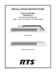
KP95, KP96 and KP97
Intercom Keypanels
EKP95, EKP96 and EKP97
Expansion Keypanels
NOTE: For additional information describing the installation of the KP95R-00 Keypanel, refer to
the KP95R-00 Installation Instructions, part number 9330-7122-000.
™
9330-7101-000 Rev F 8/94
TABLE OF CONTENTS
SECTION 1
KEYPANEL INSTALLATION . . . . . . . . . . . . . . . . . . . . . . . . . . . . . . . . . . . . . . . . . . . . . . . . . . . . . . . . . . . . . . . . . . . . . . . 1-1
GENERAL . . . . . . . . . . . . . . . . . . . . . . . . . . . . . . . . . . . . . . . . . . . . . . . . . . . . . . . . . . . . . . . . . . . . . . . . . . . . . . . . . . . . . 1-1
UNPACKING AND INSPECTION . . . . . . . . . . . . . . . . . . . . . . . . . . . . . . . . . . . . . . . . . . . . . . . . . . . . . . . . . . . . . . . . . . 1-1
SETTING THE DIP SWITCHES. . . . . . . . . . . . . . . . . . . . . . . . . . . . . . . . . . . . . . . . . . . . . . . . . . . . . . . . . . . . . . . . . . . . 1-1
DISPLAY TYPE SELECTION. . . . . . . . . . . . . . . . . . . . . . . . . . . . . . . . . . . . . . . . . . . . . . . . . . . . . . . . . . . . . . . . . . 1-1
LISTEN KEY WINK. . . . . . . . . . . . . . . . . . . . . . . . . . . . . . . . . . . . . . . . . . . . . . . . . . . . . . . . . . . . . . . . . . . . . . . . . . 1-1
LOGICAL KEYPANEL NUMBER . . . . . . . . . . . . . . . . . . . . . . . . . . . . . . . . . . . . . . . . . . . . . . . . . . . . . . . . . . . . . . 1-1
BAUD RATE. . . . . . . . . . . . . . . . . . . . . . . . . . . . . . . . . . . . . . . . . . . . . . . . . . . . . . . . . . . . . . . . . . . . . . . . . . . . . . . . 1-1
MOUNTING THE KEYPANEL AND EXPANSION PANELS . . . . . . . . . . . . . . . . . . . . . . . . . . . . . . . . . . . . . . . . . . . 1-2
CONNECTIONS. . . . . . . . . . . . . . . . . . . . . . . . . . . . . . . . . . . . . . . . . . . . . . . . . . . . . . . . . . . . . . . . . . . . . . . . . . . . . . . . . 1-2
CONNECTION TO INTERCOM MATRIX . . . . . . . . . . . . . . . . . . . . . . . . . . . . . . . . . . . . . . . . . . . . . . . . . . . . . . . 1-2
OPTIONAL CONNECTIONS . . . . . . . . . . . . . . . . . . . . . . . . . . . . . . . . . . . . . . . . . . . . . . . . . . . . . . . . . . . . . . . . . . 1-3
POWER-UP AND OPERATIONAL CHECK. . . . . . . . . . . . . . . . . . . . . . . . . . . . . . . . . . . . . . . . . . . . . . . . . . . . . . . . . . 1-4
POWER-UP SEQUENCE . . . . . . . . . . . . . . . . . . . . . . . . . . . . . . . . . . . . . . . . . . . . . . . . . . . . . . . . . . . . . . . . . . . . . . 1-4
SECTION 2
ELECTRICAL ADJUSTMENTS. . . . . . . . . . . . . . . . . . . . . . . . . . . . . . . . . . . . . . . . . . . . . . . . . . . . . . . . . . . . . . . . . . . . . . 2-1
SETTING THE INTERNAL JUMPERS . . . . . . . . . . . . . . . . . . . . . . . . . . . . . . . . . . . . . . . . . . . . . . . . . . . . . . . . . . . . . . 2-1
DEFAULT SETTINGS . . . . . . . . . . . . . . . . . . . . . . . . . . . . . . . . . . . . . . . . . . . . . . . . . . . . . . . . . . . . . . . . . . . . . . . . 2-1
J201 (EXTERNAL INPUT MUTING) . . . . . . . . . . . . . . . . . . . . . . . . . . . . . . . . . . . . . . . . . . . . . . . . . . . . . . . . . . . . 2-1
J202 (SPEAKER/HDST MUTE) . . . . . . . . . . . . . . . . . . . . . . . . . . . . . . . . . . . . . . . . . . . . . . . . . . . . . . . . . . . . . . . . 2-1
J203 (SIDETONE MUTING) . . . . . . . . . . . . . . . . . . . . . . . . . . . . . . . . . . . . . . . . . . . . . . . . . . . . . . . . . . . . . . . . . . . 2-1
J401 (OUTPUT ENABLE) . . . . . . . . . . . . . . . . . . . . . . . . . . . . . . . . . . . . . . . . . . . . . . . . . . . . . . . . . . . . . . . . . . . . . 2-1
J402 (BALANCE TEST). . . . . . . . . . . . . . . . . . . . . . . . . . . . . . . . . . . . . . . . . . . . . . . . . . . . . . . . . . . . . . . . . . . . . . . 2-1
J403 (PREAMP OUT) . . . . . . . . . . . . . . . . . . . . . . . . . . . . . . . . . . . . . . . . . . . . . . . . . . . . . . . . . . . . . . . . . . . . . . . . . 2-1
J404-J406 (PANEL MIC SELECTION) . . . . . . . . . . . . . . . . . . . . . . . . . . . . . . . . . . . . . . . . . . . . . . . . . . . . . . . . . . . 2-1
AUDIO LEVEL ADJUSTMENTS. . . . . . . . . . . . . . . . . . . . . . . . . . . . . . . . . . . . . . . . . . . . . . . . . . . . . . . . . . . . . . . . . . . 2-3
GENERAL . . . . . . . . . . . . . . . . . . . . . . . . . . . . . . . . . . . . . . . . . . . . . . . . . . . . . . . . . . . . . . . . . . . . . . . . . . . . . . . . . . 2-3
MICROPHONE PRE-AMPLIFIER . . . . . . . . . . . . . . . . . . . . . . . . . . . . . . . . . . . . . . . . . . . . . . . . . . . . . . . . . . . . . . 2-3
SPEAKER/HEADSET AMPLIFIER ADJUSTMENTS . . . . . . . . . . . . . . . . . . . . . . . . . . . . . . . . . . . . . . . . . . . . . . 2-4
KP95/96/97 Keypanel Installation i
SECTION 1
KEYPANEL INSTALLATION
1.1 GENERAL
1.3 SETTING THE DIP SWITCHES
The keypanel installation procedure consists of:
The DIP switches are located on the back of the keypanel.
They control the following functions:
1.
Unpacking and inspecting the equipment.
2.
Setting the keypanel DIP switches.
3.
Mounting the keypanel and expansion panels in an
equipment rack or bay.
4.
Connecting the keypanel to the expansion panels and to
the intercom system.
5.
Connecting any other optional equipment.
6.
Powering up the keypanel and expansion panels, and
checking operation.
1.3.1 DISPLAY TYPE SELECTION
SW1-1 selects the keypanel display type:
Open: Alpha-numeric displays
Closed: LED displays
SW1-2 selects the expansion panel display type:
Open: Alpha-numeric displays
Closed: LED displays
Note: If no expansion panels are connected, the position
of SW1-2 does not matter.
Note: There are several internal jumpers and level
adjustments which can be reset to modify the keypanel
operation and audio input/output levels. For further
information, refer to Section 2 of this manual before
proceeding with the installation.
1.3.2 LISTEN KEY WINK
1.2 UNPACKING AND INSPECTION
When winking is on, the Listen key LED will wink while
the associated Talk key is on. This helps provide a visual
indication of any active talk paths in low-light conditions.
There should be one power cord for each keypanel and
expansion panel and a 3-ft ribbon cable for each
expansion panel. There should also be a gooseneck
microphone for each keypanel (unless keypanels were
ordered without microphones). Other optional accessories
may also be packed in the container.
As soon as possible after receipt, inspect the container
and its contents for physical damage that may have
occurred in shipping. If damage has occurred,
immediately (within 24 hours of receipt of equipment)
contact the carrier involved and file a claim. Save all
packing materials, and request an immediate inspection
by the carrier’s insurance claims agent.
Notify the RTS Systems shipping department if a
shipment has been damaged in transit. Notify the RTS
Systems sales department if equipment is to be returned
for repair, or if a warranty claim is to be made. A return
authorization number, issued by the sales department, is
required for all items returned to RTS.
SW1-3 turns winking on or off:
Open: Wink off
Closed: Wink on
1.3.3 LOGICAL KEYPANEL NUMBER
SW1-4 to SW1-7 select the logical keypanel number.
To set the logical keypanel number on a keypanel:
1.
Determine the intercom audio channel number that the
keypanel will be connected to.
2.
For channel numbers ending in 1 through 9, the logical
keypanel number is the last digit of the channel
number. If the last digit is zero, use 10 as the logical
keypanel number.
3.
After determining the logical keypanel number, set DIP
switches SW1-4 to SW1-7 using Table 1-1.
1.3.4 BAUD RATE
SW1-8 selects the baud rate for communication with the
intercom matrix.
Open: 9600 baud (CS9500 Intercom Systems only)
Closed: 76,800 baud (CS9600 and CS9700 Intercom
Systems only)
KP95/96/97 Keypanel Installation
1-1
Table 1-1
DIP Switch Settings for Logical Keypanel Numbers
Logical
Keypanel
Number
1
2
3
4
5
6
7
8
9
10
1.5.1 CONNECTION TO INTERCOM MATRIX
DIP Switch Settings
SW1-4
Closed
Open
Closed
Open
Closed
Open
Closed
Open
Closed
Open
SW1-5
Open
Closed
Closed
Open
Open
Closed
Closed
Open
Open
Closed
SW1-6
Open
Open
Open
Closed
Closed
Closed
Closed
Open
Open
Open
1.5 CONNECTIONS
Use either FRAME connector to connect the keypanel to
the intercom system. The two connectors are wired in
parallel, and only one should be used. Connector pin-outs
are shown in Tables 1-2 and 1-3. Figure 1-1 shows the
cable wiring diagrams.
Table 1-2
DE9S FRAME Connector Pin-out
SW1-7
Open
Open
Open
Open
Open
Open
Open
Closed
Closed
Closed
Pin
1
2
3
4
5
6
7
8
9
1.4 MOUNTING THE KEYPANEL AND
EXPANSION PANELS
Keypanels may be mounted in any industry standard 483
mm (19") wide equipment rack. For all panels, allow an
additional 2 to 3 inches in back for cables and connectors.
No special tools other than those found in a typical tool
kit are required for mounting. The keypanels have no
special ventilation requirements.
RJ-11
CONNECTOR
Function
RS422 Data “+”
RS422 Data “-”
Ground, Shield Input
Audio Output “+”
Audio Output “-”
Ground, Shield Data
Audio Input “-”
Audio Input “+”
Ground
Table 1-3
RJ-11 FRAME Connector Pin-out
Pin
1
2
3
4
5
6
Function
RS422 Data “-”
Audio Input “+”
Audio Output “+”
Audio Output “-”
Audio Input “-”
RS422 Data “+”
USING THE RJ-11 CONNECTOR
MATRIX
NOTE 1
DATA
6, 1
6, 1
DATA
3, 4
3, 4
AUDIO IN
2, 5
2, 5
AUDIO OUT
USING THE DE9S CONNECTOR
DE9S
CONNECTOR
MATRIX
NOTE 2
1, 2
(6)
1, 2
(6)
DATA
4, 5
(9)
4, 5
(9)
AUDIO IN
8, 7
(3)
8, 7
(3)
AUDIO OUT
NOTES
1) 3 PAIRS TWISTED TELCO CABLE.
2) 3 PAIRS 20-24 AWG TWISTED, SHIELDED OR UNSHIELDED.
IF SHIELDED, CONNECT SHIELDS AT ONE END ONLY.
KEYPANEL
3) USE ONLY ONE OF THE KEYPANEL FRAME CONNECTORS.
Figure 1-1. Keypanel to Matrix Interconnect Cables
1-2
KP95/96/97 Keypanel Installation
1.5.2 OPTIONAL CONNECTIONS
1.5.2.3 Terminal Block Connections
1.5.2.1 HEADSET Connector (KP95-0 Keypanel
and KP-96-RC Option Only)
(Reference Figure 21-2)
AMP OUT “+” and “-” : These terminals provide the
keypanel audio amplifier output signal to drive an 8-ohm,
3-watt speaker. As supplied from the factory, jumpers
connect these terminals to the SPKR IN “+” and “-”
terminals. Remove these jumpers only if the keypanel
audio output is to be redirected to an external speaker.
Table 1-4 lists the HEADSET connector pin functions.
Table 1-4
HEADSET Connector Pin-out
Pin
1
2
3
4
5
6
7
8
9
Function
Dynamic mic “+” input
Dynamic mic common (shield)
Carbon mic “+” input
Carbon mic common (shield)
Headphone “+”
Dynamic mic “-” input
HDST switch control
HDST switch common
Headphone common
SPKR IN “+” and “-” : These terminals connect to the
internal speaker.
GRP CALL (Group Call): As supplied from the factory, a
jumper connects this terminal to the ground terminal for
normal Talk key operation. For external group call,
remove the jumper, and connect a normally open
footswitch between this terminal and the ground terminal.
When the footswitch is pressed, all Talk keys that are
latched in the “up” position will be activated. When the
footswitch is released, they will be deactivated.
EXT MUTE (KP-96-RC Option Only) : This terminal
may be used to drive external devices (such as
open-collector circuits) at no greater than 2 mA sinking
current. Its normal logic state is low (0 Vdc). It shifts to
logic high (+5 Vdc) when a Talk key is pressed. This
signal may be used, for example, to mute a monitor
speaker when the keypanel operator is talking on the
intercom system.
1.5.2.2 EXPANSION Connector (KP95-0
Keypanel and KP-96-RC Option Only)
To connect an expansion panel, use the ribbon cable
supplied with the expansion panel. Connect from the
EXPANSION connector on the keypanel to the
CONTROL connector on the expansion panel. If EKPD
series expansion panels are used, the second CONTROL
connector on the expansion panel may be used to connect
to an additional expansion panel. Up to three EKPD series
expansion panels may be connected, providing up to 48
additional Talk and Listen keys.
INTERNAL
SPEAKER
–
–
+
+
AMP SPKR AMP SPKR GROUP
CALL
OUT IN
IN
OUT
TS1
TERMINAL
BLOCK
EXTERNAL
SPEAKER
1
2
3
4
5
DRIVER
EXT.
MUTE
6
7
JUMPER JUMPER
EXTERNAL DRIVER
DEVICE CIRCUIT
FOOT
SWITCH
Figure 1-2. Optional Terminal Block Connections
KP95/96/97 Keypanel Installation
1-3
1.5.2.4 EXT MIC IN (KP-96-RC Option Only)
An external microphone can be connected. The external
microphone may be used with or without a front panel
gooseneck microphone of the same type. (Internal
keypanel jumpers J404-J406 must be set for the type of
microphone (see Setting the Internal Jumpers, Section 2).
Table 1-5
EXT MIC IN Connector Pin-out
Pin
1
2
3
Function
Shield
Mic in “+”
Mic in “-”
1.5.2.5 EXT LINE IN (KP-96-RC Option Only)
An external balanced audio source, such as program
sound, can be connected. The source input must be at a
nominal line level of +8dBu.
Table 1-6
EXT LINE IN Connector Pin-out
Pin
1
2
3
Function
Shield
Line in “+”
Line in “-”
1.5.2.6 MIC PRE OUT (KP-96-RC Option Only)
This connector provides a balanced mic output signal of
+8 dBu at 60 ohms. As supplied, the MIC PRE OUT
signal is activated only when a Talk key is pressed. If you
want this output to be on continuously, you must reset
internal jumper J403 (see Setting the Internal Jumpers,
Section 2).
Table 1-7
MIC PRE OUT Connector Pin-out
Pin
1
2
3
Function
Shield
Mic out “+”
Mic out “-”
1.6 POWER-UP AND OPERATIONAL
CHECK
1.6.1 POWER-UP SEQUENCE
Plug in the ac power cords on the keypanel and any
connected expansion panels.
Turn on the power switches on the keypanel and any
connected expansion panels. Observe the power-up
sequence:
1.6.1.1 Keypanels with Alpha-Numeric Displays
When power is turned on, all alpha-numeric displays will
first display asterisks (****) then dashes (----). After a
few moments, the Talk key assignments will display. If
no Talk key assignments have yet been programmed, the
displays will continue to show dashes (----).
1-4
KP95/96/97 Keypanel Installation
If the keypanel cannot establish data communications
with the intercom system, the alpha-numeric displays will
continue to show asterisks (****). Check the data line
connections.
If the keypanel displays random characters in the
alpha-numeric displays, DIP switch SW1-1 on the rear
panel may be incorrectly set. If the alpha-numeric
displays of any connected expansion panels display
random characters, DIP switch SW1-2 on the rear panel
of the main keypanel may be incorrectly set.
If the keypanel does not display the expected key
assignments, or there is no audio to the keypanel from
other keypanels, this indicates that the rear panel DIP
switch settings for logical keypanel number may be
incorrectly set. Recheck the settings.
1.6.1.2 Keypanels with LED Displays
The LED’s will remain off. The Incoming Messages
display will first display asterisks (****) then dashes
(----).
If the keypanel cannot establish data communications
with the intercom system, the Incoming Messages
display will continue to show asterisks (****). Check the
data line connections.
If the Talk key LEDs on the main keypanel blink
randomly, or some LEDs remain on even when there are
no calls to the keypanel, DIP switch SW1-1 on the rear
panel may be incorrectly set. If the Talk key LEDs on any
connected expansion panels blink randomly, or some
LEDs remain on even when there are no calls, DIP switch
SW1-2 on the rear panel of the main keypanel may be
incorrectly set.
If the keypanel Talk key LED’s periodically turn on
briefly (this may occur at intervals of one or two
minutes), or there is no audio to the keypanel from other
keypanels, this indicates that the rear panel DIP switch
settings for logical keypanel number may be incorrectly
set. Recheck the settings.
SECTION 2
ELECTRICAL ADJUSTMENTS
2.1 SETTING THE INTERNAL JUMPERS
2.1.4 J203 (SIDETONE MUTING)
2.1.1 DEFAULT SETTINGS
When pins 1 and 2 are shorted, the sidetone signal is
always on. When pins 2 and 3 are shorted, the sidetone
signal is on only when a Talk key is pressed.
There are several internal jumpers which modify keypanel
operation. The jumpers are set for the following default
operations:
2.1.5 J401 (OUTPUT ENABLE)
J201
The EXT LINE IN signal (KP-96-RC option
only) is muted when any Talk key is pressed.
When the jumper is installed, the microphone is on only
when any Talk key is pressed. When the jumper is
removed, the microphone will always be on.
J202
The speaker (or headphones) are muted by
15 dB when any Talk key is pressed.
2.1.6 J402 (BALANCE TEST)
J203
Continuous sidetone (When using a headset,
the keypanel operator’s own voice will be
heard at all times in their headphones.)
For normal operation, there should be no jumper installed.
This jumper is used when adjusting the keypanel audio
levels. See Balance Adjustment, page 2-3.
J401
The microphone is automatically activated
when any Talk key is pressed.
2.1.7 J403 (PREAMP OUT)
J402
Normal/test switch set for normal operation.
J403
The MIC PRE OUT signal (KP-96-RC
option only) is activated only when any
Talk key is pressed.
J404-J406
The keypanel is configured for operation
with the standard dynamic, -70dB, 150-ohm
gooseneck microphone.
To reset any of the jumpers, remove the top cover from
the keypanel. Locations of the jumpers are shown in
Figure 2-1. The following paragraphs describe the
alternative settings for the jumpers.
2.1.2 J201 (EXTERNAL INPUT MUTING)
This jumper is only significant in KP96 and KP97 Series
Keypanels that have the KP-96-RC Rear Connector Plate
option installed. When pins 2 and 3 are shorted, a signal
input at the EXT LINE IN connector is muted when any
Talk key is pressed. When pins 1 and 2 are shorted, the
signal is not muted during Talk key activation.
2.1.3 J202 (SPEAKER/HDST MUTE)
When pins 1 and 2 are shorted, the speaker/headset signal
is fully muted when any Talk keys are pressed. When
pins 2 and 3 are shorted, the signal is muted by 15 dB
when any Talk keys are pressed.
This jumper is only significant in KP96 and KP97 Series
Keypanels that have the KP-96-RC Rear Connector Plate
option installed. When pins 1 and 2 are shorted, the mic
signal at the MIC PRE OUT connector is switched on
and off by the Talk keys. When pins 2 and 3 are shorted,
the mic signal at the MIC PRE OUT connector is always
on.
2.1.8 J404-J406 (PANEL MIC SELECTION)
These jumpers work together to configure the panel
microphone preamp for various types of microphones as
follows:
2-Wire Electret:
J404 Pins 1 and 2 shorted
J405 No jumper
J406 No jumper
3-Wire Electret:
J404 No jumper
J405 No jumper
J406 No jumper
Balanced Dynamic (-70 dB, 150 ohms):
J404 Pins 2 and 3 shorted
J405 Pins 1 and 2 shorted
J406 Pins 1 and 2 shorted
KP95/96/97 Keypanel Installation
2-1
Figure 2-1. Locations of Jumpers and Trimpots
J404
J406
RV402
RV401 RV407
J405
P4
RV403
RV404
RV404
RV408
J402
RV409
TP 407
J401
KP95/96/97 Keypanel Installation
RV405
RV406
J403
2-2
U302
Y301
1
SW1
8
P10
U314
U305
U309
P2
U203
J203
RV206
RV209
RV203
RV205
P11 RV202
RV201
J201
RV204
P6
J202
Q402
RV207
RV208
P1
2.2 AUDIO LEVEL ADJUSTMENTS
2.2.1 GENERAL
The following paragraphs describe the procedures to
calibrate the output level to the factory standard of +8
dBu. If a different level is required, substitute that level
for +8 dBu.
Most audio level trimpots are accessible through access
holes on the back of the keypanel. Each trimpot access
hole is labelled with its function. Some trimpots are
internal, and can only be accessed with the top cover
removed. Locations of trimpots are shown in Figure 2-1.
Audio levels may be adjusted with the panel disconnected
from the intercom system. However, proper operation
should be confirmed when the panel is re-connected. If
levels change after re-connection, check the intercom
system wiring for one-sided shorts to ground, wiring
errors, or unintended terminations.
The following procedures make use of the additional
connectors available on the KP95-0 Keypanel or the
KP-96-RC Rear Connector Plate option. Connector
pin-outs for these connectors were presented earlier in
this section. If the keypanel under adjustment does not
have these connectors, refer to drawing number
IKP-950/2-5 (in the KP95, KP96 and KP97 Keypanel
Drawings Manual). This drawing shows equivalent
locations where test equipment may be connected.
Required test equipment:
Audio Signal Generator with balanced output
Audio Signal Analyzer with balanced input
DC Millivoltmeter
Oscilloscope - any commercially available type
2.2.2 MICROPHONE PRE-AMPLIFIER
9.
Check the Total Harmonic Distortion (THD) from
200 Hz to 15 KHz at +18 dBu output. It should be
less than or equal to 0.15 percent.
2.2.2.1 Balance Adjustment
1.
Turn the COMPR trimpot (RV405) fully
counter-clockwise. This sets the compressor circuit to
minimum (compressor ratio of 1:1).
2.
Measure and record the dc voltage at test point TP407.
3.
Install a shorting plug across J402.
4.
Measure the dc voltage at TP407, and adjust RV408
(internal) to match (within 5 mV) the previously
recorded voltage.
5.
Remove the shorting plug at J402.
2.2.2.2 Tone Generator Level Adjustment
1.
Activate the 400 Hz tone generator in the keypanel
(enter 0-8-7 on the keypad, or use CSedit).
2.
Adjust the LEVEL TO MATRIX trimpot (RV406) for a
+8 dBu tone output level at the MIC PRE OUT
connector.
3.
Turn off the tone generator (press CLR on the keypad,
or use CSedit). (If you turned the tone generator on
using CSedit, you must turn it off using CSedit.)
2.2.2.3 Panel Mic Level Adjustment
Activate the microphone by setting a Talk key to the
latched-up position.
Insert a -70 dBm signal (1 KHz at 150 ohms) into the
gooseneck microphone connector. Or use the EXT
MIC IN connector (with the front panel microphone
removed).
3.
Check the level at the MIC PRE OUT connector (ref
Table 1-7 for pin-out). It should measure +8 dBu.
Adjust the PNL trimpot (RV401) for +8 dBu at the
MIC PRE OUT connector.
4.
If the reading is not +8 dBu, but within a 3 dB range,
adjust the LEVEL TO MATRIX trimpot (RV406) for
+8 dBu.
Insert a common mode signal (120 Hz, -70 dBm) into
the gooseneck microphone connector, or into the
EXT MIC IN connector.
5.
Adjust RV402 (internal) for a minimum common mode
signal at the MIC PRE OUT connector.
6.
Re-insert a -70 dBm signal.
7.
Remove the shorting plug across J401 (causes
continuous mic activation).
Remove the gooseneck microphone, and insert a -70
dBm signal (1KHz at 150 ohms) into the microphone
connector. Or use the EXT MIC IN connector with
the front panel microphone removed (ref Table 1-5
for pin-out).
6.
Check the input noise. It should be at least -70 dB
below +8 dBu.
2.
2.
5.
8.
Configure the J404-J406 jumper blocks for a balanced
dynamic panel microphone: J404 short pins 2-3; J405
short pins 1-2; J406 short pins 1-2. (This is the
default microphone configuration.)
Set the HDST switch to off.
4.
Check the frequency response from 200 Hz to 15 KHz.
It should be within 1 dB.
1.
1.
3.
7.
If the reading is more than 3 dB from +8 dBu, or
another output level is used by your facility, proceed
to paragraph 2.2.2.1 to begin the mic preamp
calibration procedures.
KP95/96/97 Keypanel Installation
2-3
8.
Monitor the level at the audio output pins of the
FRAME connector, P10 (reference Table 1-2 for
pin-out). The output level should be +8 dBu.
9.
Remove the signal from the mic input, and re-install the
shorting plug across J401.
operation of the compression circuit by increasing
and reducing input levels and measuring output ratio
accordingly.
2.2.3 SPEAKER/HEADSET AMPLIFIER
ADJUSTMENTS
2.2.2.4 Headset Dynamic-Mic Level
2.2.3.1 Matrix-to-Speaker Gain
1.
Insert a -60 dBm signal (1 KHz at 150 ohms) into the
dynamic mic input of the HEADSET connector
(reference Table 1-4 for pin-out).
1.
Disconnect the loudspeaker (either internal or external)
from the + AMP OUT and - AMP OUT terminals on
the back of the keypanel.
2.
Activate the HDST key on the front of the keypanel.
2.
3.
Monitor the signal level at the MIC PRE OUT
connector. It should be +8 dBu. If not, adjust the
DYN HDST trimpot (RV403) to achieve an output
reading of +8 dBu.
Terminate the + AMP OUT and - AMP OUT terminals
with an 8-ohm, 10-watt resistive load. Connect an
audio analyzer across the load.
3.
Remove the keypanel audio connection from the
intercom matrix.
4.
Insert a +8 dBu (1 KHz) signal into the audio input “+”
and “-” pins of the FRAME connector, P10 (Table
1-2).
4.
Insert a common mode signal into the dynamic mic
input of the HEADSET connector.
5.
Adjust RV404 (internal) for a minimum common mode
signal at the MIC PRE OUT connector.
5.
Turn the front panel HDST switch off.
Remove the signal at the dynamic mic input.
6.
Turn the front panel intercom audio level control (outer
knob) fully clockwise (maximum volume).
7.
Adjust the SPKR trimpot (RV207) to measure
4.9V RMS (3 watts) at the audio analyzer. There
should be no clipping of the output signal.
8.
Turn the front panel intercom audio level control fully
counter-clockwise (minimum volume). Adjust the
MIN I/C trimpot (RV202) to measure -30 dB below
the 4.9V AC reference level.
Readjust the front panel intercom audio level control to
again measure 4.9V AC at the audio analyzer.
6.
2.2.2.5 Headset Carbon-Mic Level
1.
Insert a -25 dBm signal (1 KHz at 50 ohms) into the
carbon mic input of the HEADSET connector
(reference Table 1-4 for pin-out).
Note: A +12 vdc bias voltage is supplied at pin 3 (carbon
mic + input) of the HEADSET connector. The signal
generator should be isolated from this dc bias voltage.
2.
Activate the HDST key on the front of the keypanel.
9.
3.
Monitor the signal level at the MIC PRE OUT
connector. It should be +8 dBu. If not, adjust the
CARBON HDST trimpot (RV407) to achieve an
output reading of +8 dBu.
10. Insert a 1 KHz common mode signal into the audio
input “+” and “-” pins of the FRAME connector.
4.
Remove the signal from the carbon mic input.
11. Adjust RV201 (internal) for a minimum common
mode signal.
2.2.2.6 Compressor/AGC Set-up
12. Remove the signal from the FRAME connector.
1.
2.2.3.2 Line Input-to-Speaker Gain Adjustment
Insert a -60 dBm signal (1 KHz at 150 ohms) into the
front panel microphone connector. Or use the EXT
MIC IN connector (with the front panel microphone
removed).
1.
Install a shorting plug across J201, pins 2 and 3.
2.
Adjust the COMPR trimpot (RV405) to measure
+13 dBu at the audio output of the FRAME
connector, P10.
Insert a +8 dBu (1 KHz) signal into the EXT LINE IN
connector (reference Table 1-6 for pin-out).
3.
The HDST switch should be off.
3.
Reduce the input signal level to -80 dBm.
4.
Turn the line input level control (inner knob on the front
panel) fully counter-clockwise.
4.
Adjust RV409 (internal) for a +4 dBu audio output
level at the FRAME connector.
5.
Adjust the MIN EXT trimpot (RV205) to measure -30
dB below a reference level of 4.9V AC level at the
audio analyzer connected to the amplifier output.
2.
5.
Perform this procedure several times to optimize the
compression ratio accuracy. This will test
compression at a 2:1 ratio (0.5 dBu). Confirm correct
2-4
KP95/96/97 Keypanel Installation
6.
Readjust the line input level control to measure
4.9V AC output at the audio analyzer.
1.
Install a shorting plug across pins 1-2 of J203.
7.
Insert a 1KHz common mode signal into the EXT LINE
IN connector.
2.
Insert a -70 dBm signal (1KHz at 150 ohms) into the
dynamic mic input of the HEADSET connector .
Adjust RV204 (internal) for a minimum common mode
signal.
3.
Turn on the HDST switch, and monitor the signal level
across the 8-ohm load at the headphone output of the
HEADSET connector.
4.
Adjust the SIDETONE trimpot (RV209) to 35 dB
below a 2V AC reference level. (The level may be
varied according to user preference.)
5.
Remove the test equipment.
8.
9.
2.2.3.5 Sidetone Level Adjust
Insert a +8 dBu (1 KHz) signal into the EXT LINE IN
connector and record the output reading.
10 Remove the signal from the EXT LINE IN connector,
and insert it into the audio input “+” and “-” pins of
the FRAME connector, P10.
11. Remove the shorting plug from jumper block J201.
The output reading should be the same as in step 9.
2.2.3.3 Speaker Muting Set-up
1.
Short pins 2 and 3 of jumper block J202.
2.
Insert a +8 dBu signal (1 KHz) into the audio input pins
of the FRAME connector, P10.
3.
Alternately activate and deactivate a front panel Talk
key while adjusting the SPKR MUTE trimpot
(RV203) to provide 15 dB muting at the + AMP
OUT and - AMP OUT terminals during Talk switch
activation.
4.
Short pins 1 and 2 of J202. Insert a +8 dBu signal (1
KHz) into the audio input of the FRAME connector.
5.
Activate a front panel Talk key, and check that the
amplifier output is fully muted. Restore the J202
shorting plug to pins 2-3.
6.
Remove the 8-ohm load from the amplifier output, and
reconnect the speaker.
2.2.3.4 Headphone Level Adjust
1.
Terminate the headphone output of the HEADSET
connector (pins 5 and 9) with an 8-ohm, 10-watt
resistive load. Connect an audio analyzer across the
load.
2.
Set the front panel HDST switch to on.
3.
Insert a +8 dBu signal (1 KHz) into the audio input of
the FRAME connector.
4.
Adjust the HDST trimpot (RV208) for 2V RMS (500
milliwatts) at the headphone output.
5.
Set the front panel HDST switch to off.
6.
Adjust the HDST MUTE trimpot (RV206) for 6 dB
muting below the 2V AC reference level.
KP95/96/97 Keypanel Installation
2-5