1
DEC 3000 Model 800/800S/900 AXP
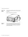
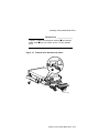
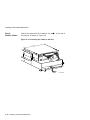
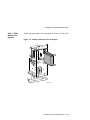
Options Guide
Order Number: EK–FLMUL–OP. B01
Digital Equipment Corporation, Maynard, Massachusetts
First Printing, May, 1994
Digital Equipment Corporation makes no representations that the use of its
products in the manner described in this publication will not infringe on
existing or future patent rights, nor do the descriptions contained in this
publication imply the granting of licenses to make, use, or sell equipment or
software in accordance with the description.
Possession, use, or copying of the software described in this publication
is authorized only pursuant to a valid written license from Digital or an
authorized sublicensor.
© Digital Equipment Corporation 1994. All Rights Reserved.
The following are trademarks of Digital Equipment Corporation: Alpha AXP,
AXP, Bookreader, DEC, DECaudio, DECchip, DECconnect, DEC GKS, DEC
PHIGS, DECsound, DECwindows, DECwindows Motif, DECwindows Mail,
DECwrite, DELNI, Digital, OpenVMS, OpenVMS AXP, RX26, ScriptPrinter,
ThinWire, TURBOchannel, ULTRIX, VAX, VAX DOCUMENT, VAXcluster,
VAXstation, the AXP logo, and the Digital logo.
Other trademarks are as follows:
CD is a trademark of Data General Corporation.
Open Software Foundation is a trademark of Open Software Foundation, Inc.
Motif, OSF, OSF/1, and OSF/Motif are registered trademarks of Open Software
Foundation, Inc.
ISDN is a registered trademark of Fujitsu Network Switching of America.
Mylar is a registered trademark of E.I. DuPont de Nemours & Company, Inc.
All other trademarks and registered trademarks are the property of their
respective holders.
FCC Notice: This equipment has been tested and found to comply with the
limits for a Class A digital device, pursuant to Part 15 of the FCC Rules.
These limits are designed to provide reasonable protection against harmful
interference when the equipment is operated in a commercial environment.
This equipment generates, uses, and can radiate radio frequency energy and, if
not installed and used in accordance with the instruction manual, may cause
harmful interference to radio communications. Operation of this equipment in
a residential area is likely to cause harmful interference, in which case users
will be required to correct the interference at their own expense.
S2565
This document was prepared using VAX DOCUMENT Version 2.1.
Contents
Preface . . . . . . . . . . . . . . . . . . . . . . . . . . . . . . . . . . . . . . . . . . . . . . . . . . . . .
vii
1 Options Overview
External Options . . . . . . . . . . . . . . . . . . . . . . . . . . . . . . . . . . . . . . . . . . .
Internal Options . . . . . . . . . . . . . . . . . . . . . . . . . . . . . . . . . . . . . . . . . . . .
1–1
1–2
2 Preparing to Add Internal Options
IMPORTANT: Read First . . . . . .
Chapter Overview . . . . . . . . . . .
Going to Console Mode . . . . . . . .
Displaying the Configuration . . .
Shutting Down Hardware . . . . .
Removing Panels . . . . . . . . . . . .
Using an Antistatic Wrist Strap .
Where to Go from Here . . . . . . .
.
.
.
.
.
.
.
.
.
.
.
.
.
.
.
.
.
.
.
.
.
.
.
.
.
.
.
.
.
.
.
.
.
.
.
.
.
.
.
.
.
.
.
.
.
.
.
.
.
.
.
.
.
.
.
.
.
.
.
.
.
.
.
.
.
.
.
.
.
.
.
.
.
.
.
.
.
.
.
.
.
.
.
.
.
.
.
.
.
.
.
.
.
.
.
.
.
.
.
.
.
.
.
.
.
.
.
.
.
.
.
.
.
.
.
.
.
.
.
.
.
.
.
.
.
.
.
.
.
.
.
.
.
.
.
.
.
.
.
.
.
.
.
.
.
.
.
.
.
.
.
.
.
.
.
.
.
.
.
.
.
.
.
.
.
.
.
.
.
.
.
.
.
.
.
.
.
.
.
.
.
.
.
.
.
.
.
.
.
.
.
.
.
.
.
.
.
.
.
.
.
.
.
.
.
.
.
.
.
.
.
.
.
.
.
.
.
.
.
.
.
.
.
.
.
.
.
.
.
.
.
.
.
.
.
.
.
.
.
.
.
.
.
.
.
.
.
.
2–1
2–1
2–2
2–4
2–9
2–10
2–16
2–17
.
.
.
.
.
.
.
.
.
.
.
.
.
.
.
.
.
.
.
.
.
.
.
.
.
.
.
.
.
.
.
.
.
.
.
.
.
.
.
.
.
.
.
.
.
.
.
.
.
.
.
.
.
.
.
.
.
.
.
.
.
.
.
.
.
.
.
.
.
.
.
.
.
.
.
.
.
.
.
.
.
.
.
.
.
.
.
.
.
.
.
.
.
.
.
.
3–1
3–1
3–2
3–15
.
.
.
.
.
.
.
.
.
.
.
.
.
.
.
.
.
.
.
.
.
.
.
.
.
.
.
.
.
.
.
.
.
.
.
.
.
.
.
.
.
.
.
.
.
.
.
.
.
.
.
.
.
.
.
.
.
.
.
.
.
.
.
.
.
.
.
.
4–1
4–1
4–2
4–5
3 Installing a Removable-Media Drive
IMPORTANT: Read First . . . . . . . . .
Chapter Overview . . . . . . . . . . . . . .
Installing a Removable-Media Drive
Removing a Removable-Media Drive
.
.
.
.
.
.
.
.
.
.
.
.
.
.
.
.
4 Installing and Removing a Fixed Disk Drive
IMPORTANT: Read First . . . .
Chapter Overview . . . . . . . . .
Installing a Fixed Disk Drive .
Removing a Fixed Disk Drive
.
.
.
.
.
.
.
.
.
.
.
.
.
.
.
.
.
.
.
.
.
.
.
.
.
.
.
.
.
.
.
.
.
.
.
.
.
.
.
.
.
.
.
.
.
.
.
.
.
.
.
.
.
.
.
.
.
.
.
.
.
.
.
.
iii
5 Memory Modules
IMPORTANT: Read First . . . . . . . . . .
Chapter Overview . . . . . . . . . . . . . . .
Determining What Modules You Need
Before Installing . . . . . . . . . . . . . . . .
Installing Memory Modules . . . . . . . .
Removing Memory Modules . . . . . . . .
.
.
.
.
.
.
.
.
.
.
.
.
.
.
.
.
.
.
.
.
.
.
.
.
.
.
.
.
.
.
.
.
.
.
.
.
.
.
.
.
.
.
.
.
.
.
.
.
.
.
.
.
.
.
.
.
.
.
.
.
.
.
.
.
.
.
.
.
.
.
.
.
.
.
.
.
.
.
.
.
.
.
.
.
.
.
.
.
.
.
.
.
.
.
.
.
.
.
.
.
.
.
.
.
.
.
.
.
.
.
.
.
.
.
.
.
.
.
.
.
.
.
.
.
.
.
.
.
.
.
.
.
.
.
.
.
.
.
.
.
.
.
.
.
.
.
.
.
.
.
.
.
.
.
.
.
.
.
.
.
.
.
5–1
5–1
5–2
5–4
5–6
5–13
.
.
.
.
.
.
.
.
.
.
.
.
.
.
.
.
.
.
.
.
.
.
.
.
.
.
.
.
.
.
.
.
.
.
.
.
.
.
.
.
.
.
.
.
.
.
.
.
.
.
.
.
.
.
.
.
.
.
.
.
.
.
.
.
.
.
.
.
.
.
.
.
.
.
.
.
.
.
.
.
.
.
.
.
.
.
.
.
.
.
.
.
.
.
.
.
.
.
.
.
.
.
.
.
.
.
.
.
.
.
.
.
.
.
.
.
.
.
.
.
.
.
.
.
.
.
.
.
.
.
.
.
.
.
.
.
.
.
.
.
6–1
6–1
6–2
6–5
6–9
.
.
.
.
.
.
.
.
.
.
.
.
.
.
.
.
.
.
.
.
.
.
.
.
.
.
.
.
.
.
.
.
.
.
.
.
.
.
.
.
.
.
.
.
.
.
.
.
.
.
.
.
.
.
.
.
.
.
.
.
.
.
.
.
.
.
.
.
.
.
.
.
.
.
.
.
.
.
.
.
.
.
.
.
.
.
.
.
.
.
.
.
.
.
.
.
.
.
.
.
.
.
.
.
.
.
.
.
.
.
.
.
7–1
7–1
7–2
7–7
Internal Option Types You Can Add . .
Option Locations (Left Side and Front)
Option Locations (Right Side) . . . . . . .
Halt Button . . . . . . . . . . . . . . . . . . . . .
The show device Display . . . . . . . . . . .
The show memory Display . . . . . . . . . .
The show config Display . . . . . . . . . . . .
The show config Display with Error . . .
Unlocking the System Cover . . . . . . . .
Removing the System Cover . . . . . . . .
Removing the Left Side Panel . . . . . . .
Removing the Right Side Panel . . . . . .
.
.
.
.
.
.
.
.
.
.
.
.
.
.
.
.
.
.
.
.
.
.
.
.
.
.
.
.
.
.
.
.
.
.
.
.
.
.
.
.
.
.
.
.
.
.
.
.
.
.
.
.
.
.
.
.
.
.
.
.
.
.
.
.
.
.
.
.
.
.
.
.
.
.
.
.
.
.
.
.
.
.
.
.
.
.
.
.
.
.
.
.
.
.
.
.
.
.
.
.
.
.
.
.
.
.
.
.
.
.
.
.
.
.
.
.
.
.
.
.
.
.
.
.
.
.
.
.
.
.
.
.
.
.
.
.
.
.
.
.
.
.
.
.
.
.
.
.
.
.
.
.
.
.
.
.
.
.
.
.
.
.
.
.
.
.
.
.
.
.
.
.
.
.
.
.
.
.
.
.
.
.
.
.
.
.
.
.
.
.
.
.
.
.
.
.
.
.
.
.
.
.
.
.
1–3
1–4
1–5
2–3
2–4
2–5
2–6
2–8
2–10
2–11
2–13
2–14
6 TURBOchannel Options
IMPORTANT: Read First . . . . . . . . .
Chapter Overview . . . . . . . . . . . . . .
TURBOchannel Overview . . . . . . . .
Installation . . . . . . . . . . . . . . . . . . .
Removing a TURBOchannel Module
7 Restoring the System
Chapter Overview . . . . . . . . . . . . .
Storing the Wrist Strap . . . . . . . . .
Replacing Panels . . . . . . . . . . . . . .
Restarting and Testing the System
.
.
.
.
Index
Figures
1–1
1–2
1–3
2–1
2–2
2–3
2–4
2–5
2–6
2–7
2–8
2–9
iv
2–10
2–11
3–1
3–2
3–3
3–4
3–5
3–6
3–7
3–8
3–9
3–10
3–11
3–12
4–1
4–2
4–3
4–4
5–1
5–2
5–3
5–4
5–5
5–6
5–7
5–8
5–9
5–10
5–11
5–12
5–13
5–14
6–1
6–2
6–3
6–4
6–5
Removing the Front Panel . . . . . . . . . . . . . . . . . . . . .
Using the Antistatic Wrist Strap . . . . . . . . . . . . . . . .
Disconnecting Power and SCSI Cables . . . . . . . . . . . .
Removing the Drive Bracket . . . . . . . . . . . . . . . . . . .
Bracket Power Cable Connectors . . . . . . . . . . . . . . . .
Bracket SCSI Cable Connectors . . . . . . . . . . . . . . . . .
Connecting Cables to a Removable-Media Drive . . . .
Placing the Drive into the Bracket . . . . . . . . . . . . . . .
Diskette Drive Brackets and Cables . . . . . . . . . . . . . .
Positioning the Cables in the Slot . . . . . . . . . . . . . . .
Sliding the Bracket into the System . . . . . . . . . . . . .
Bracket Power Cable Opening . . . . . . . . . . . . . . . . . .
Connecting Cables to the System . . . . . . . . . . . . . . . .
Removing the Blank Bezel from the Front Panel . . . .
Fixed Disk Drive Positions . . . . . . . . . . . . . . . . . . . . .
Connecting Fixed Disk Drive SCSI and Power Cables
Installing a Fixed Disk Drive . . . . . . . . . . . . . . . . . . .
Removing a Fixed Disk Drive . . . . . . . . . . . . . . . . . .
Memory Modules . . . . . . . . . . . . . . . . . . . . . . . . . . . .
Memory Mother Board (MMB) . . . . . . . . . . . . . . . . . .
Location of MMBs and Memory Modules . . . . . . . . . .
Removing MMB Clips . . . . . . . . . . . . . . . . . . . . . . . .
Removing an MMB . . . . . . . . . . . . . . . . . . . . . . . . . .
Placing the MMBs . . . . . . . . . . . . . . . . . . . . . . . . . . .
Installing a Memory Module . . . . . . . . . . . . . . . . . . .
Installing an MMB . . . . . . . . . . . . . . . . . . . . . . . . . . .
Installing MMB Clips . . . . . . . . . . . . . . . . . . . . . . . . .
Removing MMB Clips . . . . . . . . . . . . . . . . . . . . . . . .
Removing an MMB . . . . . . . . . . . . . . . . . . . . . . . . . .
Removing a Memory Module . . . . . . . . . . . . . . . . . . .
Installing an MMB . . . . . . . . . . . . . . . . . . . . . . . . . . .
Installing MMB Clips . . . . . . . . . . . . . . . . . . . . . . . . .
TURBOchannel Option Slots . . . . . . . . . . . . . . . . . . .
TURBOchannel Option Widths . . . . . . . . . . . . . . . . .
Removing a Metal Filler Plate . . . . . . . . . . . . . . . . . .
Seating a TURBOchannel Module . . . . . . . . . . . . . . .
Securing a TURBOchannel Module . . . . . . . . . . . . . .
.
.
.
.
.
.
.
.
.
.
.
.
.
.
.
.
.
.
.
.
.
.
.
.
.
.
.
.
.
.
.
.
.
.
.
.
.
.
.
.
.
.
.
.
.
.
.
.
.
.
.
.
.
.
.
.
.
.
.
.
.
.
.
.
.
.
.
.
.
.
.
.
.
.
.
.
.
.
.
.
.
.
.
.
.
.
.
.
.
.
.
.
.
.
.
.
.
.
.
.
.
.
.
.
.
.
.
.
.
.
.
.
.
.
.
.
.
.
.
.
.
.
.
.
.
.
.
.
.
.
.
.
.
.
.
.
.
.
.
.
.
.
.
.
.
.
.
.
.
.
.
.
.
.
.
.
.
.
.
.
.
.
.
.
.
.
.
.
.
.
.
.
.
.
.
.
.
.
.
.
.
.
.
.
.
.
.
.
.
.
.
.
.
.
.
.
.
.
.
.
.
.
.
.
.
.
.
.
.
.
.
.
.
.
.
.
.
.
.
.
.
.
2–15
2–16
3–3
3–4
3–5
3–6
3–7
3–8
3–9
3–10
3–11
3–12
3–13
3–14
4–2
4–3
4–4
4–5
5–2
5–4
5–5
5–6
5–7
5–8
5–10
5–11
5–12
5–14
5–15
5–16
5–17
5–18
6–3
6–4
6–6
6–7
6–8
v
6–6
6–7
7–1
7–2
7–3
7–4
7–5
Removing a Module . . . . . . . . .
Replacing a Slot Plate . . . . . . .
Replacing the Front Panel . . . .
Replacing the Left Side Panel .
Replacing the Right Side Panel
Replacing the System Cover . . .
Locking the System Cover . . . .
.
.
.
.
.
.
.
.
.
.
.
.
.
.
.
.
.
.
.
.
.
.
.
.
.
.
.
.
.
.
.
.
.
.
.
.
.
.
.
.
.
.
.
.
.
.
.
.
.
.
.
.
.
.
.
.
.
.
.
.
.
.
.
.
.
.
.
.
.
.
.
.
.
.
.
.
.
.
.
.
.
.
.
.
.
.
.
.
.
.
.
.
.
.
.
.
.
.
.
.
.
.
.
.
.
.
.
.
.
.
.
.
.
.
.
.
.
.
.
.
.
.
.
.
.
.
.
.
.
.
.
.
.
.
.
.
.
.
.
.
.
.
.
.
.
.
.
.
.
.
.
.
.
.
.
.
.
.
.
.
.
6–10
6–11
7–2
7–3
7–4
7–5
7–6
Where to Go . . . . . . . . . . . . . . . . . . . . . . . . . . . . . . . . . . . . . .
Memory Configurations . . . . . . . . . . . . . . . . . . . . . . . . . . . . .
2–17
5–3
Tables
2–1
5–1
vi
Preface
Audience
This guide is intended for all users of the DEC 3000 Model 800
/800S/900 AXP system. It describes how to install and remove
internal options.
Purpose of This
Guide
This guide provides the following information for internal
options:
Structure of
This Guide
•
How to install
•
How to test for successful installation
•
Drive SCSI ID settings
This guide is organized as follows:
Designation
Contents
Chapter 1
Overview of options, including a list of internal
options and their locations in the system unit.
Chapter 2
What you need to do to prepare your system for
adding one or more options, including shutting
down software, checking system configurations,
shutting down hardware, and removing panels.
Chapter 3
Information on installing a CD, tape or diskette
drive in the system unit.
Chapter 4
Information on installing a fixed disk drive in
the system unit.
vii
Designation
Contents
Chapter 5
Information on memory modules, including
how to determine which modules you need,
installing them in and removing them from the
system unit.
Chapter 6
Information on TURBOchannel options,
including an overview of TURBOchannel and
the system unit option positions and installing
and removing them from the system unit.
Chapter 7
What you need to do to replace panels and
confirm that options were installed correctly
inside your system unit.
Index
Two Ways To
Add Options
There are two ways to add options inside the system unit: add
the options yourself or have a Digital service representative add
them.
If you choose to add the options, note that system preparation
takes about 20 minutes, additions take about 10 to 15 minutes
per option, and system restoration takes about 10 minutes, on
the average.
What You
Should Know
Beforehand
The instructions in this guide assume you are prepared to open
the system unit, disconnect and connect internal cables, and use
antistatic precautions. You should be familiar with concepts such
as SCSI addresses, and the following diagnostic test displays:
–
System power-up messages
–
Configuration displays resulting from the show config, show
memory, and show device console commands
For more information on these diagnostic test displays, refer to
the DEC 3000 Model 800/800S/900 AXP Owner’s Guide. For
more information on SCSI concepts, refer to Small Computer
System Interface: An Overview.
CAUTION:
Option Damage
viii
Improper addition of a drive or module could lead to damage and
failure of that drive or module, or to damage of the system. The
system warranty may not cover such a failure.
Conventions in
This Guide
The following conventions are used in this guide:
show config
Words in this format indicate commands
that you must enter exactly as shown. For
example: Use the show config command.
WARNING:
Warnings contain information to prevent
personal injury. Read these carefully.
CAUTION:
Cautions contain information to prevent
damage to equipment or software. Read
these carefully.
IMPORTANT:
Important notations contain information to
allow your system to work properly.
OpenVMS
This designation represents the OpenVMS
Alpha AXP operating system.
DEC OSF/1
This designation represents the DEC OSF
/1 Alpha AXP operating system.
Italics
Italics are used for emphasis or to indicate
the title of a manual.
ix
IMPORTANT:
Software
Product
Descriptions
The Software Product Description (SPD) is the official defining
document for software products licensed by Digital Equipment
Corporation, including third-party products licensed by Digital.
An SPD describes all important functional characteristics of the
software. The terms and conditions under which the corporation
sells and licenses its software products identify SPDs as the
documents that specify Digital’s obligation under software
warranty.
SPDs also describe a software product’s system environment,
and identify required and optional hardware and software. All
information contained in the SPD is valid in the international
marketplace.
For more information on the SPD for your operating system,
please contact your Digital sales representative.
x
1
Options Overview
External Options
A number of options are available for the system. Some, such
as drives and modules, are internal options. Others, such as a
printer or modem, are external options connected to the system
by a cable.
This chapter lists and illustrates internal options for the system
and shows where to install them in the system unit.
Options Overview 1–1
Internal Options
Internal Options
Drives
Your system unit can hold up to two half-height removablemedia drives, that is, drives from which the storage medium is
removable. To add more than two removable-media drives, you
will need an expansion box.
In addition to the removable-media drives, you can have up to
four half-height fixed disk drives in the system unit.
1–2 Options Overview
Internal Options
Internal
Options
Illustration
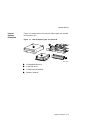
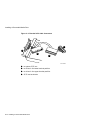
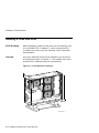
Figure 1–1 shows some of the internal option types you can add
to the system unit.
Figure 1–1 Internal Option Types You Can Add
3
1
2
4
MLO-010988
!
"
#
$
CD/tape/diskette drive
Fixed disk drive
TURBOchannel modules
Memory modules
Options Overview 1–3
Internal Options
Location
of Internal
Options: Left
Side and Front
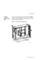
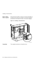
Figure 1–2 shows where to install the TURBOchannel modules
, memory modules , and removable-media drives
inside the
system unit. Note that Figure 1–2 shows the system unit with
the system cover, side panels, and front panel removed.
!
"
#
Figure 1–2 Option Locations (Left Side and Front)
2
1
3
4
MLO-012897
Note
For clarity, the rest of the figures in this manual do not
show the impingement fan . However, you do not need
to remove the impingement fan to add or install options.
$
1–4 Options Overview
Internal Options
Location
of Internal
Options: Right
Side
!
Figure 1–3 shows where to install the fixed disk drives
and
TURBOchannel modules
inside the system unit. Note that
Figure 1–3 shows the system unit with the system cover, side
panels and front panel removed.
"
Figure 1–3 Option Locations (Right Side)
2
1
MLO-007501
Options Overview 1–5
2
Preparing to Add Internal Options
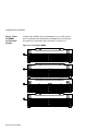
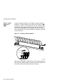
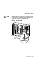
IMPORTANT: Read First
It is important to read this chapter before you install any of the
internal options described in this guide.
Chapter Overview
This chapter covers the following information:
•
Going to Console Mode
•
Displaying the Configuration
•
Shutting Down Hardware
•
Removing Panels
•
Using an Antistatic Wrist Strap
Preparing to Add Internal Options 2–1
Going to Console Mode
Going to Console Mode
Back Up Your
Files
If files are stored on a system disk, back them up following the
instructions in your software documentation.
Shut Down
Software
The procedure for shutting down your software will depend on
whether or not your system is networked.
If you are...
See your...
Networked, or part of a cluster,
system manager.
Not networked, not part of a cluster,
software documentation.
Not sure whether you are networked,
system manager.
2–2 Preparing to Add Internal Options
Going to Console Mode
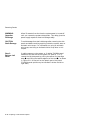
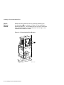
Press the Halt
Button
If you are not already in console mode (>>> prompt) after
shutting down the software, put the system into console mode by
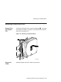
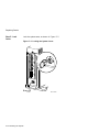
pressing the halt button. The halt button is behind the door, as
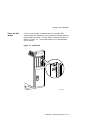
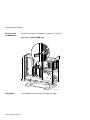
shown in Figure 2–1. The console prompt (>>>) should appear
on the monitor.
Figure 2–1 Halt Button
Line
In
MLO-007497
Preparing to Add Internal Options 2–3
Displaying the Configuration
Displaying the Configuration
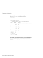
show device
Display
If you are adding one or more drives, enter the show device
command to show the drives installed in the system and their
status. You should get a display similar to what is shown in
Figure 2–2.
Figure 2–2 The show device Display
>>> show device
BOOTDEV
------ESA0
DKA0
DKA100
DKA200
DKA300
DKA400
DKA500
..HostID..
..HostID..
ADDR
DEVTYPE NUMBYTES
---------- -------08-00-2B-1D-1E-EF , THICK
A/0/0
DISK
1.05GB
A/1/0
DISK
426.25MB
A/2/0
DISK
426.25MB
A/3/0
DISK
426.25MB
A/4/0
RODISK
......
A/5/0
DISK
......
A/7
INITR
B/7
INITR
RM/FX
----FX
FX
FX
FX
RM
RM
WP DEVNAM REV
-- ------ --RZ26
RZ25
RZ25
RZ25
WP RRD42
RX26
T368
0700
0700
0700
4.3d
0068
>>>
How to Read
the show
device Display
You should see the SCSI address for each drive in the ADDR
column, as shown in Figure 2–2. The drive model is shown
in the DEVNAM column. In this example, A/3/0 indicates an
address of 3 on the SCSI-A (internal device) bus for an RZ25
drive. B/7 indicates the initiator (SCSI controller) for the SCSI-B
(external device) bus.
You can have only one of each address (0-6) on each SCSI bus.
Use the show device output to choose an unused SCSI address
for drives you add to your system.
2–4 Preparing to Add Internal Options
Displaying the Configuration
What You Need
to Do
Record the information in the ADDR and DEVNAM columns for
later reference. After adding a drive, you can compare the new
system configuration with the previous one to make sure that all
drives, including the ones you added, are present and functioning
correctly.
If your drive does not display, it may be set to the same SCSI ID
address as another drive. Change the SCSI address setting to
ensure that each drive has a unique address.
The show
memory
Display
If you are adding or removing memory modules, enter the
show memory command to display the amount of memory in the
system.
Figure 2–3 The show memory Display
>>> show memory
DEC 3000 - M800 Memory: 64 Mbytes
------------------------------ ----------BANK #
MEMORY_SIZE
START_ADDRESS
---------------------------0
032 Mbytes
0x00000000
1
032 Mbytes
0x02000000
2
000 Mbytes
0x00000000
3
000 Mbytes
0x00000000
4
000 Mbytes
0x00000000
5
000 Mbytes
0x00000000
6
000 Mbytes
0x00000000
7
000 Mbytes
0x00000000
>>>
How to Read
the show
memory
Display
Figure 2–3 shows an example of the display resulting from the
show memory command. In this example, banks 0 and 1 contain
64 megabytes of memory (eight 8-megabyte modules). All other
banks contain 0 megabytes, therefore, they are empty.
What You Need
to Do
Record the information shown in the BANK # and MEMORY_
SIZE columns for later reference. After adding or removing
memory modules, you can compare the new system memory
figure with the previous figure to make sure that all modules are
installed and functioning correctly.
Preparing to Add Internal Options 2–5
Displaying the Configuration
The show
config Display
If you are adding one or more TURBOchannel options, enter
the show config command to show the TURBOchannel modules
currently installed in the system.
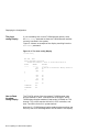
Figure 2–4 shows an example of the display resulting from the
show config command.
Figure 2–4 The show config Display
>>> show config
DEC 3000 - M800
Digital Equipment Corporation
VPP PAL X5.41-82000101 - Built on 25-JUN-1994 00:00:00.00
TCINFO
------
DEVNAM
-------CPU
ASIC
MEM
DEVSTAT
--------OK KN17-AA V1.x-SO86-IO62- DECchip 21064 P3.0
OK
OK
8
7
NVR
SCC
NI
ISDN
OK
OK
OK
OK
SCSI
OK
6
1-PMAZC-AA
TC1
0-PMAGB-BE
TC0
>>>
How to Read
the show
config Display
The TCINFO column lists the system’s TURBOchannel slots
and the modules in each. Note that slots 0 through 5 are for
TURBOchannel option modules (listed under DEVNAM as TC0
through TC5); slot 6 contains the built-in SCSI controller; and
slots 7 and 8 are for built-in system devices.
Note that if a TURBOchannel option module takes more than one
slot, only one of its slot designations will be shown in the display.
2–6 Preparing to Add Internal Options
Displaying the Configuration
The "OK" in the DEVSTAT column indicates that the device has
successfully completed the startup test.
Note that some TURBOchannel option modules do not have a
startup test, therefore, no "OK" will appear for them.
In Figure 2–4, a PMAGB-BE module is installed in slot 0, and a
PMAZC-AA is installed in slot 1. These are two TURBOchannel
option modules that may be installed in your system.
What You Need
to Do
Record the information in the TCINFO and DEVNAM columns
for later reference. After adding a module, you can compare the
new system configuration with the previous one to make sure
that all modules are present and functioning correctly.
How to Identify
Errors
If two question marks appear in the DEVSTAT column of the
show config display, an error has been detected for that module.
If an error indicator appears, as shown in Figure 2–5, follow
these steps:
1. Use the show error command, as shown in Figure 2–5, and
note the FRU and error numbers. In this example, the FRU
is 004, and the error number is 0060. The FRU is a field
replaceable unit, a drive or module that can be replaced by
your Digital service representative.
2. Refer to the DEC 3000 Model 800/800S/900 AXP Owner’s
Guide. It will explain how to contact your Digital service
representative.
Preparing to Add Internal Options 2–7
Displaying the Configuration
Figure 2–5 The show config Display with Error
>>> show config
DEC 3000 - M800
Digital Equipment Corporation
VPP PAL X5.41-82000101 - Built on 25-JUN-1994 00:00:00.00
TCINFO
------
DEVNAM
-------CPU
ASIC
MEM
DEVSTAT
--------OK KN17-AA V1.x-SO86-IO62- DECchip 21064 P3.0
OK
OK
8
7
NVR
SCC
NI
ISDN
OK
? 60
OK
OK
SCSI
OK
6
1-PMAZC-AA
TC1
0-PMAGB-BE
TC0
>>> show error
?? 004
SCC 0x0060
>>>
See Chapter 7 for information on testing TURBOchannel options.
If no error indicators appear, proceed with shutting down the
hardware.
2–8 Preparing to Add Internal Options
Shutting Down Hardware
Shutting Down Hardware
Shutdown
Sequence
Turn off (O) the equipment in the following order:
1. System unit
2. Expansion boxes
3. Printer and modem
4. Monitor (Note that turning off the system unit will not
automatically turn off the monitor.)
Leave the power cord plugged into the electrical outlet to help
protect against static discharge, which might otherwise damage
internal components.
Preparing to Add Internal Options 2–9
Removing Panels
Removing Panels
Selecting
Panels
Depending on the options you plan to add, you may not need to
remove all panels. Read the instructions for removing each panel
to determine whether or not you need to remove that panel.
To remove the panels, follow these steps:
Step 1: Unlock
Cover
Unlock the system cover, as shown in Figure 2–6.
Figure 2–6 Unlocking the System Cover
3
2
ISDN
S3
4
1
5
0
MLO-011186
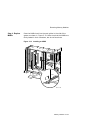
2–10 Preparing to Add Internal Options
Removing Panels
Step 2:
Remove Cover
Remove the system cover by sliding it forward and lifting it off,
as shown in Figure 2–7. Note that the cover must be removed
before you can remove the front panel or either side panel.
Figure 2–7 Removing the System Cover
MLO-007503
Preparing to Add Internal Options 2–11
Removing Panels
WARNING:
Capacitor
Discharge
Allow 15 seconds from the time the system power is turned off
until you remove the system’s side panels. This delay gives the
power supply capacitors time to discharge safely.
CAUTION:
Static Damage
To avoid damage from static discharge after removing the side
panels and before touching anything inside the system, wear an
antistatic wrist strap. For information on using an antistatic
wrist strap, see Using an Antistatic Wrist Strap later in this
chapter.
Step 3:
Remove Left
Panel
If adding memory to the system, or if adding TURBOchannel
modules to the left side of the system unit (slots 0, 1, or 2);
remove the left side panel by pulling the tabs on the top edge
away
and lifting the bottom edge out of the track , as shown
in Figure 2–8. Do not pull on the plastic part of the panel.
(TURBOchannel options may be installed in either the left or
right side.)
!
2–12 Preparing to Add Internal Options
"
Removing Panels
Figure 2–8 Removing the Left Side Panel
1
2
MLO-011187
Preparing to Add Internal Options 2–13
Removing Panels
Step 4:
Remove Right
Panel
If adding one or more fixed disk drives or a removable-media
drive to the system unit, or if adding TURBOchannel modules
to the right side of the system unit (slots 3, 4, or 5); remove
the right side panel by pulling the tabs on the top edge away
and lifting the bottom edge out of the track , as shown
in Figure 2–9. Do not pull on the plastic part of the panel.
(TURBOchannel options may be installed in either the left or
right side.)
!
"
Figure 2–9 Removing the Right Side Panel
1
2
MLO-007505
2–14 Preparing to Add Internal Options
Removing Panels
Step 5:
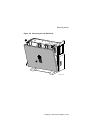
Remove Front
Panel
If adding one or two removable-media drives to the system,
remove the front panel by releasing the catches at the top .
and unhook the panel bottom , as
Pull the panel away
shown in Figure 2–10.
"
!
#
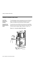
Figure 2–10 Removing the Front Panel
1
2
3
MLO-011188
Preparing to Add Internal Options 2–15
Using an Antistatic Wrist Strap
Using an Antistatic Wrist Strap
CAUTION:
Component
Damage
To avoid damage to internal components from static discharge,
wear an antistatic wrist strap before handling any drive or
module, and before touching anything inside the system.
Putting On an
Antistatic Wrist
Strap
To use the wrist strap, follow the instructions on the envelope.
Note that the wrist strap may be attached to the metal surface
of either side of the power supply, as shown in Figure 2–11.
Figure 2–11 Using the Antistatic Wrist Strap
MLO-011189
2–16 Preparing to Add Internal Options
Where to Go from Here
Where to Go from Here
To Install a
Specific Option
Each of the following chapters covers the installation of one
type of option. To add a particular internal option, refer to the
chapter indicated in Table 2–1.
Table 2–1 Where to Go
To install a
Refer to
Removable-media drive
Chapter 3
Fixed disk drive
Chapter 4
Memory modules
Chapter 5
TURBOchannel modules
Chapter 6
Preparing to Add Internal Options 2–17
3
Installing a Removable-Media Drive
IMPORTANT: Read First
Your system must be prepared before you can install this drive.
See Chapter 2 to:
•
Back up files.
•
Shut down the system software.
•
Display the show device screen to review the SCSI ID
addresses for each drive in the system. Refer to the option
documentation if you need to set or change a SCSI ID
address.
•
Shut down the system hardware.
•
Remove panels.
•
Attach the antistatic wrist strap.
Chapter Overview
This chapter covers the following topics:
•
Installing a Removable-Media Drive
•
Removing a Removable-Media Drive
Installing a Removable-Media Drive 3–1
Installing a Removable-Media Drive
Installing a Removable-Media Drive
SCSI ID Setting
Before proceeding, make sure the drive you are installing is set
to an available SCSI ID address. To set or change the SCSI
ID address on the drive you are installing, refer to your drive’s
owner’s guide.
Overview
Removable-media drives are installed in a bracket in the front
of the system unit. These are the steps involved inpreparing to
install or replace a removable-media drive:
Step
Action
1
Disconnect the power and SCSI cables.
2
Remove the bracket.
3
Identify the power and SCSI cables.
4
Connect the cables to the drive.
5
Place the drive in the bracket.
6
Position the cables.
7
Slide the bracket into the system.
8
Guide the bracket power cable.
9
Connect the cables to the system.
10
Tighten the thumbscrews.
11
Remove the blank filler plate.
The following sections describe these steps.
3–2 Installing a Removable-Media Drive
Installing a Removable-Media Drive
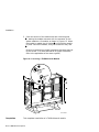
Step 1:
Remove Cables
from System
Disconnect the power and SCSI cables on the right side of the
system, as shown in Figure 3–1. The power and SCSI cables for
the bracket are shown in Figure 3–3 and Figure 3–4.
Figure 3–1 Disconnecting Power and SCSI Cables
MLO-011263
Installing a Removable-Media Drive 3–3
Installing a Removable-Media Drive
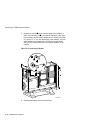
Step 2:
Remove
Bracket
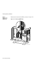
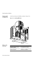
Remove the drive bracket from the system by releasing the
two thumbscrews , as shown in Figure 3–2 and pulling the
bracket straight out. The thumbscrews will pop out a little when
they are fully loosened. If the thumbscrews are too tight, use a
screwdriver to loosen the screws.
!
Figure 3–2 Removing the Drive Bracket
1
MLO-011190
3–4 Installing a Removable-Media Drive
Installing a Removable-Media Drive
Step 3: Identify
Power and
SCSI Cables
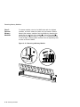
Each cable has several connectors. Refer to Figure 3–3 and
Figure 3–4 when making cable connections.
Figure 3–3 Bracket Power Cable Connectors
1
2
3
4
MLO-007510
!
"
#
$
to system power harness
to CD and other removable-media drives in the upper bracket
position
to removable-media drives in the lower bracket position
to the second power connector on a diskette drive only
Installing a Removable-Media Drive 3–5
Installing a Removable-Media Drive
Figure 3–4 Bracket SCSI Cable Connectors
4
1
2
3
MLO-009887
!
"
#
$
to system SCSI bus
to drives in the lower bracket position
to drives in the upper bracket position
SCSI bus terminator
3–6 Installing a Removable-Media Drive
Installing a Removable-Media Drive
Step 4:
Connect Cables
to Drive
!
"
Connect the SCSI
and power
cables to the ports on the rear
of the drive, as shown in Figure 3–5. The connectors are keyed;
make sure that they are oriented correctly before attempting to
insert them into the drive ports.
Figure 3–5 Connecting Cables to a Removable-Media Drive
2
5V+5%
GND
12V+10
%
UT
DC INP
L
GND
AUDIO
R
OUT
0 1 2
T
ID SELEC
MODE
F.GND
1
MLO-007515
Installing a Removable-Media Drive 3–7
Installing a Removable-Media Drive
Step 5: Place
Drive in
Bracket
Place the drive in the bracket, as shown in Figure 3–6, and using
the screws that came with the drive, secure it with two screws
on each side.
Figure 3–6 Placing the Drive into the Bracket
MLO-011197
Position in
Bracket
There are two drive positions for the bracket. Mount the CD
drive in the upper position, as shown in Figure 3–6, so that it is
on the left after the bracket is reinstalled. If a drive other than
another CD drive occupies this upper position, move the other
drive to the lower position.
3–8 Installing a Removable-Media Drive
Installing a Removable-Media Drive
Diskette Drive
!
Figure 3–7 shows the extension brackets
and second
power cable
that you attach to the 3.5-inch diskette
drive.
"
Figure 3–7 Diskette Drive Brackets and Cables
2
1
MLO-010993
Installing a Removable-Media Drive 3–9
Installing a Removable-Media Drive
Step 6:
Position Cables
! at the rear of
Position the power and SCSI cables in the slot
the bracket, as shown in Figure 3–8.
Figure 3–8 Positioning the Cables in the Slot
5V+5%
GND
U
DC INP
L
GND
AUDIO
R
OUT
1 1 2
T
ID SELEC
MODE
F.GND
1
MLO-009392
3–10 Installing a Removable-Media Drive
Installing a Removable-Media Drive
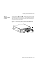
Step 7: Slide
Bracket into
System
Slide the bracket partly into the system, as shown in Figure 3–9.
Figure 3–9 Sliding the Bracket into the System
MLO-011191
Installing a Removable-Media Drive 3–11
Installing a Removable-Media Drive
Step 8: Guide
Bracket Power
Cable
Guide the bracket power cable through the opening
right side of the system, as shown in Figure 3–10.
! into the
Figure 3–10 Bracket Power Cable Opening
1
MLO-011264
3–12 Installing a Removable-Media Drive
Installing a Removable-Media Drive
Step 9:
Connect Cables
to System
Connect the SCSI cable to the SCSI bus connector, and the power
cable to the power harness, as shown in Figure 3–11.
Figure 3–11 Connecting Cables to the System
MLO-011265
Step 10:
Tighten
Thumbscrews
Slide the bracket all the way in, and tighten the two
thumbscrews.
Installing a Removable-Media Drive 3–13
Installing a Removable-Media Drive
Step 11:
Remove Blank
Bezel
Remove the blank bezel from the front panel, as shown in
Figure 3–12. Push the bezel out from the sides. Pushing from
the middle may break the bezel. This bezel is on the left as you
face the front of the panel. When installing two drives, remove
both blank bezels.
Figure 3–12 Removing the Blank Bezel from the Front Panel
MLO-007584
Save the blank bezel in case you ever remove the drive and need
to replace the bezel.
Completion
This completes the installation of a removable-media drive.
3–14 Installing a Removable-Media Drive
Removing a Removable-Media Drive
Removing a Removable-Media Drive
Removal Steps
To take a removable-media drive out of the system unit, follow
these steps:
1. Disconnect the SCSI and power cables from the system.
2. Release the two thumbscrews and remove the drive bracket
from the system.
3. Disconnect the SCSI and power cables from the drive.
4. Remove the two screws on each side of the drive bracket that
secure the drive.
5. Lift the drive out of the bracket.
6. Replace the bracket in the system unit and tighten the two
thumbscrews.
7. Reconnect the system SCSI and power cables.
8. Install the filler plate.
Where to Go
from Here
If you
Refer to
Have other options to add
inside the system,
The appropriate chapter.
Have no other options to add
inside the system,
Chapter 7 to replace the panels
and check the system.
Installing a Removable-Media Drive 3–15
4
Installing and Removing a Fixed Disk
Drive
IMPORTANT: Read First
Your system must be prepared before you can install this drive.
See Chapter 2 to:
•
Back up files.
•
Shut down the system software.
•
Display the show device screen to review the SCSI ID
addresses for each drive in the system.
•
Shut down the system hardware.
•
Remove panels.
•
Attach the antistatic wrist strap.
Chapter Overview
This chapter covers the following topics:
•
Installing a Fixed Disk Drive
•
Removing a Fixed Disk Drive
Installing and Removing a Fixed Disk Drive 4–1
Installing a Fixed Disk Drive
Installing a Fixed Disk Drive
SCSI ID Setting
Before proceeding, make sure the drive you are installing is set
to an available SCSI ID address. To set or change the SCSI
ID address on the drive you are installing, refer to the option
documentation.
Overview
Up to four fixed disk drives can be installed in any of the four
drive positions shown in Figure 4–1. The numbers refer to the
preferred SCSI addresses for given drive positions.
Figure 4–1 Fixed Disk Drive Positions
2
3
1
0
MLO-007574
4–2 Installing and Removing a Fixed Disk Drive
Installing a Fixed Disk Drive
Step 1:
Connect Cables
!
"
Connect the SCSI
and power
connectors to the fixed disk
drive, as shown in Figure 4–2. The connectors are keyed; make
sure that they are oriented correctly before attempting to insert
them into the drive.
Figure 4–2 Connecting Fixed Disk Drive SCSI and Power
Cables
1
2
MLO-008539
Installing and Removing a Fixed Disk Drive 4–3
Installing a Fixed Disk Drive
Step 2: Attach
Drive to System
Orient the drive as shown in Figure 4–3, insert the bumpers on
the bottom of the drive into the holes in the mounting position,
and slide the drive towards the latch, until the latch engages.
Figure 4–3 Installing a Fixed Disk Drive
MLO-008538
Completion
This completes installation of a fixed disk drive.
4–4 Installing and Removing a Fixed Disk Drive
Removing a Fixed Disk Drive
Removing a Fixed Disk Drive
Remove Drive
from System
Unit
!
To remove a fixed disk drive, press the release latch
at the top
of the drive, as shown in Figure 4–4, and slide the drive up and
away from the system unit.
Figure 4–4 Removing a Fixed Disk Drive
1
MLO-009720
Disconnect
Cables
Remove the power and SCSI cables from the drive.
Installing and Removing a Fixed Disk Drive 4–5
Removing a Fixed Disk Drive
Where to Go
from Here
If you
Refer to
Have other options to add
inside the system,
The appropriate chapter.
Have no other options to add
inside the system,
Chapter 7 to restore and check
the system.
4–6 Installing and Removing a Fixed Disk Drive
5
Memory Modules
IMPORTANT: Read First
Your system must be prepared before you can install memory
modules. See Chapter 2 to:
•
Back up files.
•
Shut down the system software.
•
Display the show memory screen to review the memory
configuration already installed.
•
Shut down the system hardware.
•
Remove the system panels.
•
Attach the antistatic wrist strap.
Chapter Overview
This chapter covers the following topics:
•
Determining What Modules You Need
•
Memory from Other Systems
•
Configuration Table
•
Installing Memory Modules
•
Removing Memory Modules
Memory Modules 5–1
Determining What Modules You Need
Determining What Modules You Need
Memory Module
Sizes
Memory modules are available in 4-megabyte, 8-megabyte, 16megabyte, and 32-megabyte sizes. 4-megabyte and 16 megabyte
modules have components on one side. 8-megabyte and 32megabyte modules have components on both sides (front and
back).
Figure 5–1 shows the memory modules.
Figure 5–1 Memory Modules
MLO-007563
System
Memory
To increase the system’s memory capacity, you can order memory
upgrades. For a particular memory configuration, see Table 5–1.
The system can hold a maximum of 1 gigabyte of memory (32
32-megabyte memory modules).
Configuration
Table
5–2 Memory Modules
Table 5–1 provides an example of which modules need to be
installed for a given total amount of memory.
Determining What Modules You Need
Table 5–1 Memory Configurations
Desired
Memory
Modules to Add
32 MB
Eight 4-MB modules
64 MB
Eight 8-MB modules
64 MB
Sixteen 4-MB modules
96 MB
Eight 4-MB and Eight 8-MB modules
96 MB
Twenty-four 4-MB modules
128 MB
Eight 16-MB modules
128 MB
Sixteen 8-MB modules
160 MB
Eight 4-MB and Sixteen 8-MB modules
192 MB
Sixteen 4-MB and Sixteen 8-MB modules
192 MB
Twenty-four 8-MB modules
256 MB
Eight 32-MB modules
256 MB
Sixteen 16-MB modules
384 MB
Twenty-four 16-MB modules
512 MB
Sixteen 32-MB modules
512 MB
Thirty-two 16-MB modules
768 MB
Twenty-four 32-MB modules
1 GB
Thirty-two 32-MB modules
Note that modules are installed in sets of eight (two modules
on each of four memory mother boards (MMBs), as shown in
Figure 5–2).
Memory from
Other Systems
Do not attempt to use memory modules from any other system in
the system. Other modules are not necessarily compatible with
this system.
Memory Modules 5–3
Before Installing
Before Installing
CAUTION:
Memory Module
Damage
To avoid damage from static discharge after removing the left
side panel and before opening the shipping bag for any memory
module, and before touching anything inside the system, wear
an antistatic wrist strap. See Using an Antistatic Wrist Strap in
Chapter 2 for more information.
Handle memory modules by their edges to avoid damaging and
contaminating the module pins and connectors.
Memory Mother
Boards (MMBs)
Memory modules are installed onto four memory mother boards
(MMBs), which are installed into the system. Figure 5–2 shows
an MMB with two memory modules installed on it.
Figure 5–2 Memory Mother Board (MMB)
MLO-007564
5–4 Memory Modules
Before Installing
Where to Install
Figure 5–3 shows the location of MMBs with memory modules
inside the system.
Figure 5–3 Location of MMBs and Memory Modules
MLO-011192
Memory Modules 5–5
Installing Memory Modules
Installing Memory Modules
To install memory modules in the system, follow these steps:
Step 1:
Remove the
MMB Clips
Remove the two clips from the MMBs, as shown in Figure 5–4.
Figure 5–4 Removing MMB Clips
MLO-011193
5–6 Memory Modules
Installing Memory Modules
Step 2:
Remove the
MMBs
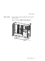
Remove all four MMBs from their channels by releasing the
catches and sliding the boards out, as shown in Figure 5–5.
Figure 5–5 Removing an MMB
MLO-011194
Memory Modules 5–7
Installing Memory Modules
Step 3: Place
the MMBs
on Protected
Surface
Place the four MMBs, with the connectors up, on a flat surface
that is protected from electrostatic discharge (such as the top of
the system or an antistatic mat), as shown in Figure 5–6.
Figure 5–6 Placing the MMBs
1
1
2
3
4
1
1
2
3
4
1
1
2
3
4
1
1
2
3
4
MLO-009721
5–8 Memory Modules
Installing Memory Modules
Guidelines for
Installing
The following guidelines should be used when installing memory
modules:
•
Modules must be added in sets of eight, adding two modules
to each of the four MMBs.
•
Add modules starting at the empty MMB slots with the
lowest numbers. Add two modules to the corresponding
on each MMB, as shown by the shaded areas in
slots
Figure 5–6.
!
•
Use the same size (MB) modules for a set of eight slots. For
example, you might add a set of eight 4-MB modules or a set
of eight 8-MB modules, but do not mix 4- and 8-MB modules
within a set. If you do mix different sizes of memory modules
within a set, your system will not recognize some of the
memory.
Memory Modules 5–9
Installing Memory Modules
Step 4: Install
Modules in
MMB
Install the memory modules in the MMBs, using the previous
guidelines. Hold the module at an angle, with the notch end
as shown in Figure 5–7, and place it in the slot. Make sure that
the board is firmly seated in the connector, but do not force it.
Push the board upright so that it stands vertically. You should
hear a distinctive click on each side when the module is secured
by the metal clips.
!
Figure 5–7 Installing a Memory Module
1
MLO-007566
Working from the lower numbered slots to the higher numbered
slots, continue adding modules in empty slots of the MMBs until
the system contains the desired amount of memory.
5–10 Memory Modules
Installing Memory Modules
Step 5: Install
MMBs
Install the MMBs into the card guides in the side of the system,
as shown in Figure 5–8. Make sure that the MMBs are firmly
seated in their connectors, but do not force them.
Figure 5–8 Installing an MMB
MLO-011195
Memory Modules 5–11
Installing Memory Modules
Step 6: Install
the MMB Clips
Install the two clips on the MMBs, as shown in Figure 5–9.
Figure 5–9 Installing MMB Clips
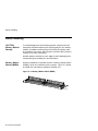
MLO-011196
Completion
5–12 Memory Modules
This completes installation of the memory modules.
Removing Memory Modules
Removing Memory Modules
You may need to remove memory modules at some time, such as
when replacing them with higher capacity modules. To remove
modules, see the following steps.
IMPORTANT:
System Needs
Note that the system will not operate if no memory modules
are installed. You must have at least one set of eight memory
modules.
Memory Modules 5–13
Removing Memory Modules
Step 1:
Remove the
MMB Clips
Remove the two clips from the MMBs, as shown in Figure 5–10.
Figure 5–10 Removing MMB Clips
MLO-011193
5–14 Memory Modules
Removing Memory Modules
Step 2:
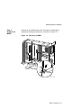
Remove MMBs
Remove all four MMBs from their channels by releasing the
catches and sliding the boards out, as shown in Figure 5–11.
Figure 5–11 Removing an MMB
MLO-011194
Memory Modules 5–15
Removing Memory Modules
Step 3:
Remove
Memory
Modules
To remove modules, start at the MMB slots with the highest
numbers, and work toward the slots with the lowest numbers.
Remove the memory modules from the MMBs by releasing the
metal clips at each end of the module , tilting the module ,
and lifting it out , as shown in Figure 5–12. Remove modules
in sets of eight, removing both modules from corresponding slots
on each of the four MMBs.
!
#
"
Figure 5–12 Removing a Memory Module
1
2
3
MLO-007567
5–16 Memory Modules
Removing Memory Modules
Step 4: Replace
MMBs
Place the MMBs back into the card guides in the side of the
system, as shown in Figure 5–13. Make sure that the MMBs are
firmly seated in their connectors, but do not force them.
Figure 5–13 Installing an MMB
MLO-011195
Memory Modules 5–17
Removing Memory Modules
Step 5: Install
the MMB Clips
Install the two clips on the MMBs, as shown in Figure 5–14.
Figure 5–14 Installing MMB Clips
MLO-011196
Where to Go
from Here
5–18 Memory Modules
If you
Refer to
Have other options to add
inside the system,
The appropriate chapter.
Have no other options to add
inside the system,
Chapter 7 to replace the panels
and check the system.
6
TURBOchannel Options
IMPORTANT: Read First
Your system must be prepared before you can install
TURBOchannel modules. See Chapter 2 to:
•
Back up files
•
Shut down the system software
•
Determine what options your system has
•
Shut down the system hardware
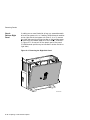
•
Remove panels
•
Attach the antistatic wrist strap
Chapter Overview
This chapter covers descriptions, installation, and removal of
TURBOchannel options.
TURBOchannel Options 6–1
TURBOchannel Overview
TURBOchannel Overview
What It Is
TURBOchannel is a high-performance module interconnect
technology that permits the use of graphics, multimedia,
and communications options. Refer to your Software Product
Descriptions (SPD) for available options.
Third-Party
Options
Although this chapter covers TURBOchannel option modules
manufactured by Digital, other companies have developed
modules that may be compatible with the system. Consult your
Digital sales representative for more information.
System
TURBOchannel
Slots
The system unit has six TURBOchannel option module slots:
three on the system module (left side of the system), and three
on the I/O module (right side of the system).
Note that, since Figure 6–1 shows the rear of the system, the left
side of the system is on the right side of the figure (slots 0, 1,
and 2), and the right side of the system is on the left side of the
figure (slots 3, 4, and 5).
6–2 TURBOchannel Options
TURBOchannel Overview
Figure 6–1 TURBOchannel Option Slots
3
3
2
2
1
ISDN
S3
4
4
1
5
5
0
MLO-011198
TURBOchannel Options 6–3
TURBOchannel Overview
TURBOchannel
Options
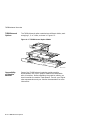
The TURBOchannel option modules have different widths, each
occupying 1, 2, or 3 slots, as shown in Figure 6–2.
Figure 6–2 TURBOchannel Option Widths
MLO-011276
Compatibility
of Graphics
Modules
Some of the TURBOchannel modules provide graphics
enhancements, but not all graphics modules are compatible
with all monitors. Before upgrading the graphics module, you
should consider the monitor requirements. Consult your Digital
sales representative and your monitor documentation for more
information.
6–4 TURBOchannel Options
Installation
Installation
Choosing a
TURBOchannel
Slot
The TURBOchannel modules plug directly into either the system
module (3 slots) or the I/O module (3 slots). See Figure 6–1.
Installation
Procedure
To install a TURBOchannel module, follow these steps:
If you are installing options, you should consider the widths of
the modules you plan to use, as well as where future options
would be placed.
1. Wear an antistatic wrist strap whenever you handle a
module or work inside the system box. See Using An
Antistatic Wrist Strap in Chapter 2.
2. Choose one or more unused TURBOchannel slots, as needed,
considering the locations and sizes of existing modules. You
may find that one or more existing modules need to be moved
to make space for a new module software configuration when
changing module slots.
TURBOchannel Options 6–5
Installation
3. Remove the two screws and metal filler plate at the chosen
slot or slots, as shown in Figure 6–3. Save the plate, in case
you remove a module later. Save the screws for attaching the
new module to the system cabinet.
Figure 6–3 Removing a Metal Filler Plate
MLO-008578
6–6 TURBOchannel Options
Installation
4. Orient the new module as shown, inserting the module port
through the slot, as shown in Figure 6–4.
Figure 6–4 Seating a TURBOchannel Module
MLO-008579
TURBOchannel Options 6–7
Installation
5. Press the corners of the module over each mounting post
, seating the module connector with the connector on the
system module or I/O module, as shown in Figure 6–5. When
the module is seated, the pin latches
will hold the module
in place. Secure the module, using two screws for every slot
.
!
"
#
Be sure to reconnect any pigtail connectors that were secured
by the screws. (For more information on pigtail connectors,
refer to the appendixes of the owner’s guide.)
Figure 6–5 Securing a TURBOchannel Module
1
3
2
MLO-008580
Completion
This completes installation of a TURBOchannel module.
6–8 TURBOchannel Options
Removing a TURBOchannel Module
Removing a TURBOchannel Module
To remove a TURBOchannel module, follow these steps:
1. Refer to Chapter 2 to prepare your system.
2. Wear an antistatic wrist strap whenever you handle a
module or work inside the system box. See Using An
Antistatic Wrist Strap in Chapter 2.
3. Remove any cables that are attached to the module that is
being removed.
4. Remove the slot screws that hold the module in place. See
in Figure 6–6.
!
TURBOchannel Options 6–9
Removing a TURBOchannel Module
"
5. Release the latches
that hold the edge of the module in
the module connector away from
place, and carefully pull
the connector on the system module or I/O module, as shown
in Figure 6–6. If you are removing a 3-slot module, you may
need assistance to release the six latches simultaneously
and pull the module away from the system module or I/O
module.
#
Figure 6–6 Removing a Module
2
3
1
MLO-008581
6. Remove the module from the system box.
6–10 TURBOchannel Options
Removing a TURBOchannel Module
7. Replace the slot plates for all emptied slots, attaching the
plates with two screws.
Figure 6–7 Replacing a Slot Plate
MLO-008578
Completion
This completes removal of a TURBOchannel module.
Where to Go
from Here
If you
Refer to
Want to connect cables to a
newly-installed module,
Your option documentation.
Have other options to add
inside the system,
The appropriate chapter.
Have no other options to add
inside the system,
Chapter 7 to replace panels and
check the system.
TURBOchannel Options 6–11
7
Restoring the System
Chapter Overview
This chapter covers the following topics:
•
Storing the Wrist Strap
•
Replacing Panels
•
Restarting and Testing the System
Storing the Wrist Strap
Refold and store the wrist strap for future use, following these
steps:
1. Remove the copper strip end of the strap from the power
supply. Replace the paper covering on the sticky surface.
2. Unwrap the strap from your wrist.
3. Fold the strap, starting at the copper strip end. Use the folds
in the strap as a guide.
4. Place the strap in the envelope and store it in a safe place.
Restoring the System 7–1
Replacing Panels
Replacing Panels
To replace the panels, follow these steps, as needed:
Step 1: Replace
Front Panel
!
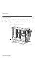
To replace the front panel, hook the bottom of the panel
under
the system, and push the top in until the latches
engage, as
shown in Figure 7–1.
"
Figure 7–1 Replacing the Front Panel
2
1
MLO-011199
7–2 Restoring the System
Replacing Panels
Step 2: Replace
Left Panel
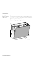
To replace the left side panel, seat the bottom edge of the panel
in the track, push down to set the panel, and press the top of the
panel in, as shown in Figure 7–2.
Figure 7–2 Replacing the Left Side Panel
MLO-011200
Restoring the System 7–3
Replacing Panels
Step 3: Replace
Right Panel
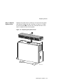
To replace the right side panel, seat the bottom edge of the panel
in the track, push down to set the panel, and press the top of the
panel in, as shown in Figure 7–3.
Figure 7–3 Replacing the Right Side Panel
MLO-007591
7–4 Restoring the System
Replacing Panels
Step 4: Replace
System Cover
Replace the system cover by seating it on the top of the system
and sliding it toward the rear, as shown in Figure 7–4. Make
sure that the hooks
face the rear, and that the lock on the
cover is toward the rear of the system.
!
Figure 7–4 Replacing the System Cover
1
MLO-007577
Restoring the System 7–5
Replacing Panels
Step 5: Lock
Cover
Lock the system cover, as shown in Figure 7–5.
Figure 7–5 Locking the System Cover
3
2
ISDN
S3
4
1
5
0
MLO-010890
7–6 Restoring the System
Restarting and Testing the System
Restarting and Testing the System
Reconnect
Cables
Reconnect all the cables that were removed during the option
installation.
Turning On
To start the system, turn on ( | ) the equipment in the following
order:
1. Monitor
2. Expansion boxes, printers, and modems
3. System
Note that although expansion boxes, printers and modems can
be turned on at any time, turning them on as listed here will
ensure that they are configured when the system is turned on.
Console
Prompt
When you turn it on, the system should give a display similar
to the show config display, then stop at the console prompt. (If
the system does not stop at the console prompt, it has been set
to boot automatically. Press the halt button to get the console
prompt.)
Recording
Startup
Messages
Write down any startup error messages. Refer to the DEC 3000
Model 800/800S/900 AXP Owner’s Guide for an explanation of
common error messages and for more information about testing
the system.
Restoring the System 7–7
Restarting and Testing the System
Testing Drive
Installation
To make sure that the drives are connected correctly, enter the
show device command as explained in Chapter 2. Compare
the latest configuration display with the display shown when
preparing the system before adding a drive. You should see
the new drive and all the drives that were present before the
addition.
If a new drive was installed, but is not in the current display, it
has not been installed properly.
Make sure that drives are set to the correct SCSI addresses.
Make sure that no error messages appear. Two question marks
in the show device display indicate an error with a drive. If any
error messages appear, write them down.
If a drive does not display, two or more drives may have been
installed with the same SCSI address, and you will need to
change them to ensure that each drive has a unique address.
Testing Memory
Installation
To make sure that the memory modules and MMBs are
connected correctly, display the system configuration by using
the show memory command as explained in Chapter 2. Compare
the latest memory configuration with the display shown when
preparing the system before adding any memory modules. You
should see the current system memory. If the memory figure is
incorrect, one or more memory modules have not been installed
properly.
Testing
TURBOchannel
Module
Installation
To make sure that the TURBOchannel modules are connected
correctly, display the system configuration by using the show
config command as explained in Chapter 2. Compare the latest
configuration display (TCINFO and DEVNAM columns) with
the display shown when preparing the system before adding a
module. You should see the new module and all the modules
that were present before the addition.
If a new module was installed, but is not in the current display,
it has not been installed properly.
7–8 Restoring the System
Restarting and Testing the System
If You Have
Problems
If the displays show an error, follow these steps, using the wrist
strap:
1. Shut down the system hardware.
2. Make sure that all cables inside and outside the system are
properly reconnected.
3. Make sure that all modules are fully seated in their
connectors.
4. Make sure SCSI address switches and jumpers are set
correctly; no two drives should be set to the same SCSI
address.
If problems persist, refer to the troubleshooting section of your
DEC 3000 Model 800/800S/900 AXP Owner’s Guide, or contact
your Digital service representative.
Restoring the System 7–9
Index
A
D
Antistatic precautions, 2–12, 5–4
Antistatic wrist strap, 2–16
connecting, 2–16
putting on, 2–16
Diagnostic displays, viii, 7–8
Diskette drive
installing, 3–2
Drive bracket
removing, 3–4
replacing, 3–11
Drives
listing, 2–5
testing configuration of, 7–8
B
Backing up files, 2–2
C
CD drive
installing, 3–2
Configuration
checking, 2–5, 2–7, 7–8
comparing old and new, 7–8
reviewing, 2–5, 2–7
show config command, 2–7, 7–8
show device command, 2–4, 7–8
show memory command, 2–5, 7–8
Configuration display, 2–5, 2–7
Configurations
memory, 5–2
Console mode
entering, 2–3, 7–7
Conventions
used in this guide, ix
Cover
removing, 2–11
replacing, 7–5
E
Error messages, 7–8
Expansion boxes
turning on, 7–7
F
File backup, 2–2
Filler plate
removing, 3–14
Fixed disk drive
installing, 4–2
removing, 4–5
H
Halt button, 2–3
Hard disk drives
See RZ25/RZ26 fixed disk drive
Index–1
Restarting the system, 7–7
I
Installation
checking, 7–7
Installation time, viii
S
Memory
configurations, 5–2
Memory modules
adding, 5–4
location in system, 5–5
protection from static discharge, 5–4
removing, 5–13
sequence for adding, 5–4
sizes, 5–2
where to install, 5–5
Modem
turning on, 7–7
Modules
listing, 2–7
Monitor
turning on, 7–7
SCSI address, 7–8
SCSI cable
connecting a fixed disk drive, 4–3
SCSI cable, connecting
to removable-media drive, 3–7
show config command, 2–7, 7–8
show device command, 2–5, 7–8
show memory command, 2–5, 7–8
Starting up, 7–7
Static discharge
precautions against, 5–4
protection against, 2–12, 2–16, 5–4
System
configuration, 2–5, 2–7
preparing, 2–1
restoring, 7–1
testing, 7–8
turning on, 7–7
System cover
removing, 2–11
replacing, 7–5
P
T
Panels
removing, 2–10
replacing, 7–2
Power cable
connecting a fixed disk drive, 4–3
Power cable, connecting
to removable-media drive, 3–7
Printer
turning on, 7–7
Problems, 7–9
Tape drive
installing, 3–2
Testing the system, 7–8
Troubleshooting, 7–9
TURBOchannel options
compatibility with monitors, 6–4
overview of, 6–2
sizes of, 6–2
Turning on the system, 7–7
M
R
Removable-media drive
installing, 3–2
Removable-media drives, 1–2
Index–2
W
Warranty coverage, viii
Wrist strap
storing, 7–1
using, 2–16
How to Order Additional Documentation
Technical Support
If you need help deciding which documentation best meets your needs, call 800-DIGITAL
(800-344-4825) and press 2 for technical assistance.
Electronic Orders
If you wish to place an order through your account at the Electronic Store, dial
800-234-1998, using a modem set to 2400- or 9600-baud. You must be using a VT
terminal or terminal emulator set at 8 bits, no parity. If you need assistance using
the Electronic Store, call 800-DIGITAL (800-344-4825) and ask for an Electronic Store
specialist.
Telephone and Direct Mail Orders
From
Call
Write
U.S.A.
DECdirect
Phone: 800-DIGITAL
(800-344-4825)
Fax: (603) 884-5597
Digital Equipment Corporation
P.O. Box CS2008
Nashua, NH 03061
Puerto Rico
Phone: (809) 781-0505
Fax: (809) 749-8377
Digital Equipment Caribbean, Inc.
3 Digital Plaza, 1st Street
Suite 200
Metro Office Park
San Juan, Puerto Rico 00920
Canada
Phone: 800-267-6215
Fax: (613) 592-1946
Digital Equipment of Canada Ltd.
100 Herzberg Road
Kanata, Ontario, Canada K2K 2A6
Attn: DECdirect Sales
International
—————
Local Digital subsidiary or
approved distributor
Internal Orders1
(for software
documentation)
DTN: 264-3030
(603) 884-3030
Fax: (603) 884-3960
U.S. Software Supply Business
Digital Equipment Corporation
10 Cotton Road
Nashua, NH 03063-1260
Internal Orders
(for hardware
documentation)
DTN: 264-3030
(603) 884-3030
Fax: (603) 884-3960
U.S. Software Supply Business
Digital Equipment Corporation
10 Cotton Road
Nashua, NH 03063-1260
1 Call
to request an Internal Software Order Form (EN–01740–07).
Reader’s Comments
DEC 3000 Model 800/800S/900 AXP
Options Guide
EK–FLMUL–OP. B01
Your comments and suggestions help us improve the quality of our publications.
Thank you for your assistance.
I rate this manual’s:
Excellent
Good
Fair
Accuracy (product works as manual says)
Completeness (enough information)
Clarity (easy to understand)
Organization (structure of subject matter)
Figures (useful)
Examples (useful)
Index (ability to find topic)
Page layout (easy to find information)
I would like to see more/less
What I like best about this manual is
What I like least about this manual is
I found the following errors in this manual:
Page
Description
Additional comments or suggestions to improve this manual:
For software manuals, please indicate which version of the software you are using:
Name/Title
Dept.
Company
Date
Mailing Address
Phone
Poor
d
Do Not Tear – Fold Here and Tape
TM
BUSINESS REPLY MAIL
FIRST CLASS PERMIT NO. 33 MAYNARD MASS.
POSTAGE WILL BE PAID BY ADDRESSEE
DIGITAL EQUIPMENT CORPORATION
Information Design and Consulting
MRO1–3/K10 JS
200 FOREST STREET
MARLBORO, MA. 01752–3011
Do Not Tear – Fold Here
No Postage
Necessary
If Mailed
in the
United States