1
DEC 3000 Model 600/600S/700 AXP
Owner’s Guide
Order Number: EK–SNDPL–OG. B01
Digital Equipment Corporation, Maynard, MA
Third Printing, May 1994
Digital Equipment Corporation makes no representations that the use of its
products in the manner described in this publication will not infringe on
existing or future patent rights, nor do the descriptions contained in this
publication imply the granting of licenses to make, use, or sell equipment or
software in accordance with the description.
Possession, use, or copying of the software described in this publication
is authorized only pursuant to a valid written license from Digital or an
authorized sublicensor.
© Digital Equipment Corporation 1994. All Rights Reserved.
The following are trademarks of Digital Equipment Corporation: Alpha AXP,
AXP, Bookreader, DEC, DECaudio, DECchip, DECconnect, DEC GKS, DEC
PHIGS, DECsound, DECwindows, DECwindows Motif, DECwindows Mail,
DECwrite, DELNI, Digital, OpenVMS, OpenVMS AXP, RX26, ScriptPrinter,
ThinWire, TURBOchannel, ULTRIX, VAX, VAX DOCUMENT, VAXcluster,
VAXstation, the AXP logo, and the Digital logo.
Other trademarks are as follows:
CD is a trademark of Data General Corporation.
Open Software Foundation is a trademark of Open Software Foundation, Inc.
Motif, OSF, OSF/1, and OSF/Motif are registered trademarks of Open Software
Foundation, Inc.
ISDN is a registered trademark of Fujitsu Network Switching of America.
Mylar is a registered trademark of E.I. DuPont de Nemours & Company, Inc.
PostScript is a registered trademark of Adobe Systems, Inc.
All other trademarks and registered trademarks are the property of their
respective holders.
FCC Notice: This equipment has been tested and found to comply with the
limits for a Class A digital device, pursuant to Part 15 of the FCC Rules.
These limits are designed to provide reasonable protection against harmful
interference when the equipment is operated in a commercial environment.
This equipment generates, uses, and can radiate radio frequency energy and, if
not installed and used in accordance with the instruction manual, may cause
harmful interference to radio communications. Operation of this equipment in
a residential area is likely to cause harmful interference, in which case users
will be required to correct the interference at their own expense.
S2560
This document was prepared using VAX DOCUMENT Version 2.1.
Contents
Preface . . . . . . . . . . . . . . . . . . . . . . . . . . . . . . . . . . . . . . . . . . . . . . . . . . . . .
xv
Part I Basic Operations
1 Introduction to Your System
Chapter Overview . . . . . . . . . . . . . . . . . . . .
System Configurations . . . . . . . . . . . . . . . . .
Overview of the System . . . . . . . . . . . . . . . .
Operating Systems . . . . . . . . . . . . . . . . . . . .
Software Product Descriptions (SPD) . . . . . .
Graphics Capabilities . . . . . . . . . . . . . . . . . .
Integrated Services Digital Network (ISDN)
Audio Capabilities . . . . . . . . . . . . . . . . . . . .
Available Options . . . . . . . . . . . . . . . . . . . . .
.
.
.
.
.
.
.
.
.
.
.
.
.
.
.
.
.
.
.
.
.
.
.
.
.
.
.
.
.
.
.
.
.
.
.
.
.
.
.
.
.
.
.
.
.
.
.
.
.
.
.
.
.
.
.
.
.
.
.
.
.
.
.
.
.
.
.
.
.
.
.
.
.
.
.
.
.
.
.
.
.
.
.
.
.
.
.
.
.
.
.
.
.
.
.
.
.
.
.
.
.
.
.
.
.
.
.
.
.
.
.
.
.
.
.
.
.
.
.
.
.
.
.
.
.
.
.
.
.
.
.
.
.
.
.
.
.
.
.
.
.
.
.
.
.
.
.
.
.
.
.
.
.
.
.
.
.
.
.
.
.
.
.
.
.
.
.
.
.
.
.
.
.
.
.
.
.
.
.
.
.
.
.
.
.
.
.
.
.
.
.
.
.
.
.
.
.
.
1–1
1–2
1–3
1–5
1–7
1–8
1–9
1–10
1–11
.
.
.
.
.
.
.
.
.
.
.
.
.
.
.
.
.
.
.
.
.
.
.
.
.
.
.
.
.
.
.
.
.
.
.
.
.
.
.
.
.
.
.
.
.
.
.
.
.
.
.
.
.
.
.
.
.
.
.
.
.
.
.
.
.
.
.
.
.
.
.
.
.
.
.
.
.
.
.
.
.
.
.
.
.
.
.
.
.
.
.
.
.
.
.
.
.
.
.
.
.
.
.
.
.
.
.
.
.
.
.
.
.
.
.
.
.
.
.
.
.
.
.
.
.
.
.
.
.
.
.
.
.
.
.
.
.
.
.
.
.
.
.
.
.
.
.
.
.
.
.
.
.
.
2–1
2–2
2–4
2–6
2–9
2–11
2–15
2 Preparing to Install Your System
Chapter Overview . . . . . . . . . . . .
Choosing a Location . . . . . . . . . . .
Customizing Your Work Area . . . .
Unpacking a Workstation System
Unpacking a Server System . . . . .
A Closer Look at Your System . . .
Where to Go Next . . . . . . . . . . . .
.
.
.
.
.
.
.
.
.
.
.
.
.
.
.
.
.
.
.
.
.
.
.
.
.
.
.
.
.
.
.
.
.
.
.
.
.
.
.
.
.
.
.
.
.
.
.
.
.
.
.
.
.
.
.
.
iii
3 Installing a Workstation System
Chapter Overview . . . . . . . .
Before You Begin . . . . . . . . .
Task Overview . . . . . . . . . . .
Connecting the Workstation .
Checking Your Installation . .
Where to Go Next . . . . . . . .
.
.
.
.
.
.
.
.
.
.
.
.
.
.
.
.
.
.
.
.
.
.
.
.
.
.
.
.
.
.
.
.
.
.
.
.
.
.
.
.
.
.
.
.
.
.
.
.
.
.
.
.
.
.
.
.
.
.
.
.
.
.
.
.
.
.
.
.
.
.
.
.
.
.
.
.
.
.
.
.
.
.
.
.
.
.
.
.
.
.
.
.
.
.
.
.
.
.
.
.
.
.
.
.
.
.
.
.
.
.
.
.
.
.
.
.
.
.
.
.
.
.
.
.
.
.
.
.
.
.
.
.
.
.
.
.
.
.
.
.
.
.
.
.
.
.
.
.
.
.
.
.
.
.
.
.
.
.
.
.
.
.
.
.
.
.
.
.
.
.
.
.
.
.
.
.
.
.
.
.
.
.
.
.
.
.
.
.
.
.
.
.
.
.
.
.
.
.
.
.
.
.
.
.
3–1
3–2
3–3
3–5
3–19
3–21
.
.
.
.
.
.
.
.
.
.
.
.
.
.
.
.
.
.
.
.
.
.
.
.
.
.
.
.
.
.
.
.
.
.
.
.
.
.
.
.
.
.
.
.
.
.
.
.
.
.
.
.
.
.
.
.
.
.
.
.
.
.
.
.
.
.
.
.
.
.
.
.
.
.
.
.
.
.
.
.
.
.
.
.
.
.
.
.
.
.
.
.
.
.
.
.
.
.
.
.
.
.
.
.
.
.
.
.
.
.
.
.
.
.
.
.
.
.
.
.
.
.
.
.
.
.
.
.
.
.
.
.
.
.
.
.
.
.
.
.
.
.
.
.
.
.
.
.
.
.
.
.
.
.
.
.
.
.
.
.
.
.
.
.
.
.
.
.
.
.
.
.
.
.
.
.
.
.
.
.
.
.
.
.
.
.
.
.
.
.
.
.
.
.
.
.
.
.
4–1
4–2
4–3
4–5
4–13
4–14
........
........
........
........
Network
........
........
.
.
.
.
.
.
.
.
.
.
.
.
.
.
.
.
.
.
.
.
.
.
.
.
.
.
.
.
.
.
.
.
.
.
.
.
.
.
.
.
.
.
.
.
.
.
.
.
.
.
.
.
.
.
.
.
.
.
.
.
.
.
.
.
.
.
.
.
.
.
.
.
.
.
.
.
.
.
.
.
.
.
.
.
5–1
5–2
5–4
5–6
5–8
5–12
5–14
.
.
.
.
.
.
.
.
.
.
.
.
.
.
.
.
.
.
.
.
.
.
.
.
.
.
.
.
.
.
.
.
.
.
.
.
.
.
.
.
.
.
.
.
.
.
.
.
.
.
.
.
.
.
.
.
.
.
.
.
.
.
.
.
.
.
.
.
.
.
.
.
.
.
.
.
.
.
.
.
.
.
.
.
6–1
6–2
6–3
6–6
6–8
6–13
6–14
4 Installing a Server System
Chapter Overview . . . . . . .
Before You Begin . . . . . . . .
Task Overview . . . . . . . . . .
Connecting the Server . . . .
Checking Your Installation .
Where to Go Next . . . . . . .
.
.
.
.
.
.
.
.
.
.
.
.
5 Connecting Your System to a Network
Chapter Overview . . . . . . . . . . . . . . . . . . . . . .
Before You Begin . . . . . . . . . . . . . . . . . . . . . . .
Connecting to an AUI Ethernet Network . . . . .
Connecting to a 10BASE-T Ethernet Network .
Connecting to a 10BASE2 (ThinWire) Ethernet
Setting and Verifying the Network Connection
Completing the Network Connection . . . . . . . .
6 Starting Up Your System
Chapter Overview . . . . . . . . . . . . . . . . . . . . . . . . .
Before You Begin . . . . . . . . . . . . . . . . . . . . . . . . . .
Turning On the System . . . . . . . . . . . . . . . . . . . . .
Reviewing the Startup Display . . . . . . . . . . . . . . .
Starting a System with Factory-Installed Software
Loading Operating System Software . . . . . . . . . . .
Where to Go Next . . . . . . . . . . . . . . . . . . . . . . . . .
iv
.
.
.
.
.
.
.
.
.
.
.
.
.
.
.
.
.
.
.
.
.
.
.
.
.
.
.
.
.
.
.
.
.
.
.
7 Turning Off Your System
Chapter Overview . . . . . . .
Before You Begin . . . . . . . .
Shutting Down the System
Halting the System . . . . . .
.
.
.
.
.
.
.
.
.
.
.
.
.
.
.
.
.
.
.
.
.
.
.
.
.
.
.
.
.
.
.
.
.
.
.
.
.
.
.
.
.
.
.
.
.
.
.
.
.
.
.
.
.
.
.
.
.
.
.
.
.
.
.
.
.
.
.
.
.
.
.
.
.
.
.
.
.
.
.
.
.
.
.
.
.
.
.
.
.
.
.
.
.
.
.
.
.
.
.
.
.
.
.
.
.
.
.
.
.
.
.
.
.
.
.
.
.
.
.
.
.
.
.
.
.
.
.
.
.
.
.
.
.
.
.
.
.
.
.
.
7–1
7–2
7–3
7–5
Chapter Overview . . . . . . . . . . . . . . . . . . . .
Before You Begin . . . . . . . . . . . . . . . . . . . . .
Maintaining the System Unit and Keyboard
Cleaning the Monitor . . . . . . . . . . . . . . . . . .
Cleaning the Mouse . . . . . . . . . . . . . . . . . . .
.
.
.
.
.
.
.
.
.
.
.
.
.
.
.
.
.
.
.
.
.
.
.
.
.
.
.
.
.
.
.
.
.
.
.
.
.
.
.
.
.
.
.
.
.
.
.
.
.
.
.
.
.
.
.
.
.
.
.
.
.
.
.
.
.
.
.
.
.
.
.
.
.
.
.
.
.
.
.
.
.
.
.
.
.
.
.
.
.
.
.
.
.
.
.
.
.
.
.
.
.
.
.
.
.
.
.
.
.
.
8–1
8–2
8–2
8–4
8–4
.
.
.
.
.
.
.
.
.
.
.
.
.
.
.
.
.
.
.
.
.
.
.
.
.
.
.
.
.
.
.
.
.
.
.
.
.
.
.
.
.
.
.
.
.
.
.
.
.
.
.
.
.
.
.
.
.
.
.
.
.
.
.
.
.
.
.
.
.
.
.
.
.
.
.
.
.
.
.
.
.
.
.
.
.
.
.
.
.
.
.
.
.
.
.
.
.
.
.
.
.
.
.
.
.
.
.
.
.
.
.
.
.
.
.
.
.
.
.
.
.
.
.
.
.
.
.
.
.
.
.
.
.
.
.
.
.
.
.
.
.
.
.
.
.
.
.
.
.
.
.
.
.
.
.
.
.
.
.
.
.
.
.
.
.
.
.
.
.
.
.
.
.
.
.
.
.
.
.
.
.
.
.
.
.
.
.
.
.
.
.
.
.
.
.
.
.
.
.
.
.
.
.
.
.
.
.
.
.
.
.
.
.
.
.
.
.
.
.
.
.
.
.
.
.
.
.
.
.
.
.
.
.
.
.
.
.
.
.
.
.
.
.
.
.
.
.
.
.
.
.
.
.
.
.
.
.
.
.
.
.
.
.
.
.
.
.
.
.
.
.
.
.
.
.
.
.
.
.
.
.
.
.
.
.
.
9–1
9–2
9–3
9–4
9–6
9–9
9–13
9–13
9–14
9–15
9–16
9–17
9–18
Chapter Overview . . . . . . . . . . . . . . . . . . . . . . . . . . . . . . . . .
Before You Begin . . . . . . . . . . . . . . . . . . . . . . . . . . . . . . . . . .
Available Environment Variables . . . . . . . . . . . . . . . . . . . . . .
Displaying Current Environment Variables . . . . . . . . . . . . . .
Changing the Default Startup Action (auto_action) . . . . . . . .
Changing the Default Boot Device (bootdef_dev) . . . . . . . . . .
Changing the Default Diagnostic Startup Mode (diag_quick) .
Changing the Default Keyboard Language (language) . . . . . .
.
.
.
.
.
.
.
.
.
.
.
.
.
.
.
.
.
.
.
.
.
.
.
.
.
.
.
.
.
.
.
.
.
.
.
.
.
.
.
.
.
.
.
.
.
.
.
.
.
.
.
.
.
.
.
.
.
.
.
.
.
.
.
.
.
.
.
.
.
.
.
.
10–1
10–2
10–2
10–4
10–5
10–7
10–9
10–10
8 Maintaining Your System
Part II Advanced Operations
9 Using Console Commands
Chapter Overview . . . . . . . . . . .
Before You Begin . . . . . . . . . . . .
Modes of System Operation . . .
Console Mode User Interface . . .
Console Commands . . . . . . . . . .
The boot Command . . . . . . . . . .
The continue Command . . . . . . .
The halt Command . . . . . . . . . .
The help Command . . . . . . . . . .
The help advanced Command . .
The set or setenv Command . . . .
The show or printenv Command
The test Command . . . . . . . . . . .
.
.
.
.
.
.
.
.
.
.
.
.
.
.
.
.
.
.
.
.
.
.
.
.
.
.
.
.
.
.
.
.
.
.
.
.
.
.
.
.
.
.
.
.
.
.
.
.
.
.
.
.
.
.
.
.
.
.
.
.
.
.
.
.
.
.
.
.
.
.
.
.
.
.
.
.
.
.
.
.
.
.
.
.
.
.
.
.
.
.
.
.
.
.
.
.
.
.
.
.
.
.
.
.
.
.
.
.
.
.
.
.
.
.
.
.
.
10 Changing Environment Variables
v
Changing the Default Fast SCSI (fast_scsi_a)(fast_scsi_b) . . . . . . . . . . . .
10–11
11 Using the Password Security Feature
Chapter Overview . . . . . . . . . . . . . .
Before You Begin . . . . . . . . . . . . . . .
Task Overview . . . . . . . . . . . . . . . .
Moving the Secure System Jumper .
Entering a Password . . . . . . . . . . . .
Enabling System Security . . . . . . . .
Using the login Command . . . . . . . .
Forgetting the Password . . . . . . . . .
Disabling or Changing the Password
.
.
.
.
.
.
.
.
.
.
.
.
.
.
.
.
.
.
.
.
.
.
.
.
.
.
.
.
.
.
.
.
.
.
.
.
.
.
.
.
.
.
.
.
.
.
.
.
.
.
.
.
.
.
.
.
.
.
.
.
.
.
.
.
.
.
.
.
.
.
.
.
.
.
.
.
.
.
.
.
.
.
.
.
.
.
.
.
.
.
.
.
.
.
.
.
.
.
.
.
.
.
.
.
.
.
.
.
.
.
.
.
.
.
.
.
.
.
.
.
.
.
.
.
.
.
.
.
.
.
.
.
.
.
.
.
.
.
.
.
.
.
.
.
.
.
.
.
.
.
.
.
.
.
.
.
.
.
.
.
.
.
.
.
.
.
.
.
.
.
.
.
.
.
.
.
.
.
.
.
.
.
.
.
.
.
.
.
.
.
.
.
.
.
.
.
.
.
.
.
.
.
.
.
.
.
.
.
.
.
.
.
.
.
.
.
.
.
.
.
.
.
.
.
.
.
.
.
.
.
.
.
.
.
.
.
.
.
.
.
.
.
.
.
.
.
.
.
.
.
.
.
11–1
11–2
11–4
11–5
11–13
11–14
11–15
11–16
11–17
Chapter Overview . . . . . . . . . . . . . . . . . . . . . . . . . . . . . . . . . . . . . . . . . .
Before You Begin . . . . . . . . . . . . . . . . . . . . . . . . . . . . . . . . . . . . . . . . . . .
Using the Alternate Console Feature . . . . . . . . . . . . . . . . . . . . . . . . . . . .
12–1
12–2
12–3
12 Using an Alternate Console
Part III Handling Problems
13 Identifying a Problem
Chapter Overview . . . . . . . . . . . . . . . . . .
Before You Begin . . . . . . . . . . . . . . . . . . .
Task Overview . . . . . . . . . . . . . . . . . . . . .
Determining Type of Problem . . . . . . . . .
Startup Problems . . . . . . . . . . . . . . . . . . .
Interpreting the show Command Displays
Display Problems . . . . . . . . . . . . . . . . . . .
Mouse and Keyboard Problems . . . . . . . .
SCSI Device Problems . . . . . . . . . . . . . . .
Network Problems . . . . . . . . . . . . . . . . . .
Where to Go Next . . . . . . . . . . . . . . . . . .
vi
.
.
.
.
.
.
.
.
.
.
.
.
.
.
.
.
.
.
.
.
.
.
.
.
.
.
.
.
.
.
.
.
.
.
.
.
.
.
.
.
.
.
.
.
.
.
.
.
.
.
.
.
.
.
.
.
.
.
.
.
.
.
.
.
.
.
.
.
.
.
.
.
.
.
.
.
.
.
.
.
.
.
.
.
.
.
.
.
.
.
.
.
.
.
.
.
.
.
.
.
.
.
.
.
.
.
.
.
.
.
.
.
.
.
.
.
.
.
.
.
.
.
.
.
.
.
.
.
.
.
.
.
.
.
.
.
.
.
.
.
.
.
.
.
.
.
.
.
.
.
.
.
.
.
.
.
.
.
.
.
.
.
.
.
.
.
.
.
.
.
.
.
.
.
.
.
.
.
.
.
.
.
.
.
.
.
.
.
.
.
.
.
.
.
.
.
.
.
.
.
.
.
.
.
.
.
.
.
.
.
.
.
.
.
.
.
.
.
.
.
.
.
.
.
.
.
.
.
.
.
.
.
.
.
.
.
.
.
.
.
.
.
.
.
.
.
.
.
.
.
.
.
.
.
.
.
.
.
.
.
.
.
.
.
13–1
13–2
13–3
13–4
13–6
13–12
13–20
13–23
13–24
13–26
13–27
14 Running Diagnostic Tests
Chapter Overview . . . . . . . . . . . . . . . .
Before You Begin . . . . . . . . . . . . . . . . .
Task Overview . . . . . . . . . . . . . . . . . . .
Running Diagnostic Tests . . . . . . . . . . .
Recording the Diagnostic Display Light
Reporting Problems to Digital Services
Handling Problems Worksheet . . . . . . .
.......
.......
.......
.......
Pattern
.......
.......
.
.
.
.
.
.
.
.
.
.
.
.
.
.
.
.
.
.
.
.
.
.
.
.
.
.
.
.
.
.
.
.
.
.
.
.
.
.
.
.
.
.
.
.
.
.
.
.
.
.
.
.
.
.
.
.
.
.
.
.
.
.
.
.
.
.
.
.
.
.
.
.
.
.
.
.
.
.
.
.
.
.
.
.
.
.
.
.
.
.
.
.
.
.
.
.
.
.
.
.
.
.
.
.
.
.
.
.
.
.
.
.
.
.
.
.
.
.
.
.
.
.
.
.
.
.
.
.
.
.
.
.
.
14–1
14–2
14–3
14–4
14–11
14–13
14–19
Appendix Overview . . . . . . . . . . . . . . . . . . . . . . . . . . . . . . . . . . . . . . . . .
System Specifications . . . . . . . . . . . . . . . . . . . . . . . . . . . . . . . . . . . . . . . .
A–1
A–2
Part IV Appendixes
A Hardware Specifications
B Port Pin-outs
Appendix Overview . . . . . . . . . . . . . . . . . . . . . . .
Alternate Console/Printer Port . . . . . . . . . . . . . . .
Synchronous/Asynchronous Communications Port
External SCSI Port . . . . . . . . . . . . . . . . . . . . . . .
Keyboard/Mouse or Tablet Port . . . . . . . . . . . . . .
AUI Ethernet Port . . . . . . . . . . . . . . . . . . . . . . . .
ISDN Port . . . . . . . . . . . . . . . . . . . . . . . . . . . . . .
10BASE-T Port . . . . . . . . . . . . . . . . . . . . . . . . . .
Audio Port . . . . . . . . . . . . . . . . . . . . . . . . . . . . . .
.
.
.
.
.
.
.
.
.
.
.
.
.
.
.
.
.
.
.
.
.
.
.
.
.
.
.
.
.
.
.
.
.
.
.
.
.
.
.
.
.
.
.
.
.
.
.
.
.
.
.
.
.
.
.
.
.
.
.
.
.
.
.
.
.
.
.
.
.
.
.
.
.
.
.
.
.
.
.
.
.
.
.
.
.
.
.
.
.
.
.
.
.
.
.
.
.
.
.
.
.
.
.
.
.
.
.
.
.
.
.
.
.
.
.
.
.
.
.
.
.
.
.
.
.
.
.
.
.
.
.
.
.
.
.
.
.
.
.
.
.
.
.
.
.
.
.
.
.
.
.
.
.
.
.
.
.
.
.
.
.
.
B–1
B–2
B–3
B–5
B–7
B–8
B–10
B–11
B–12
.
.
.
.
.
.
.
.
.
.
.
.
.
.
.
.
.
.
.
.
.
.
.
.
.
.
.
.
.
.
.
.
.
.
.
.
.
.
.
.
.
.
.
.
.
.
.
.
.
.
.
.
.
.
.
.
.
.
.
.
.
.
.
.
.
.
.
.
.
.
.
.
C–1
C–2
C–3
C–4
C Associated Documents
Appendix Overview . . . . . . . . . .
Associated Printed Documents . .
OpenVMS AXP Documentation .
DEC OSF/1 AXP Documentation
.
.
.
.
.
.
.
.
.
.
.
.
.
.
.
.
.
.
.
.
.
.
.
.
.
.
.
.
.
.
.
.
.
.
.
.
.
.
.
.
.
.
.
.
.
.
.
.
.
.
.
.
vii
D Special Information for PTT Network Users
Appendix Overview . . . . . . . . . . . . . . . . . . . . .
Service Categories . . . . . . . . . . . . . . . . . . . . . .
Host Power Rating . . . . . . . . . . . . . . . . . . . . . .
Module Isolation . . . . . . . . . . . . . . . . . . . . . . .
Safety Status . . . . . . . . . . . . . . . . . . . . . . . . . .
Cable Approval . . . . . . . . . . . . . . . . . . . . . . . .
Supported Cables . . . . . . . . . . . . . . . . . . . . . . .
Equipment Between the Approved Module and
(PTT) . . . . . . . . . . . . . . . . . . . . . . . . . . . . . . . .
..............
..............
..............
..............
..............
..............
..............
a Digital Circuit
..............
.
.
.
.
.
.
.
.
.
.
.
.
.
.
.
.
.
.
.
.
.
.
.
.
.
.
.
.
.
.
.
.
.
.
.
.
.
.
.
.
.
.
D–1
D–2
D–3
D–4
D–5
D–5
D–7
......
D–7
Glossary
Index
Figures
1–1
2–1
2–2
2–3
2–4
2–5
2–6
2–7
2–8
3–1
3–2
3–3
3–4
3–5
3–6
3–7
3–8
3–9
3–10
3–11
viii
The DEC 3000 Model 600/700 AXP Workstation . . . . . . .
Dimensions of System . . . . . . . . . . . . . . . . . . . . . . . . . . .
Positioning Your System . . . . . . . . . . . . . . . . . . . . . . . . .
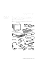
Workstation Components and Parts Used for Installation
Components and Parts to Save . . . . . . . . . . . . . . . . . . . .
Server Components and Parts Used for Installation . . . .
Components and Parts to Save . . . . . . . . . . . . . . . . . . . .
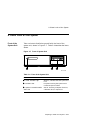
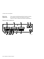
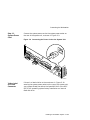
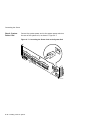
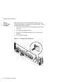
Front of System Unit . . . . . . . . . . . . . . . . . . . . . . . . . . . .
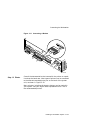
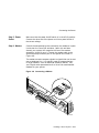
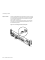
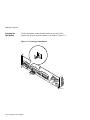
Back of System Unit . . . . . . . . . . . . . . . . . . . . . . . . . . . .
Parts Used to Install your Workstation . . . . . . . . . . . . . .
Connecting the Monitor Video Cable . . . . . . . . . . . . . . . .
Plug End of the Monitor Power Cord . . . . . . . . . . . . . . . .
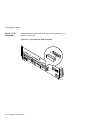
Connecting the Ethernet Loopback Connector . . . . . . . . .
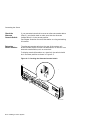
Connecting the SCSI Terminator . . . . . . . . . . . . . . . . . . .
Connecting the Keyboard/Mouse Cable . . . . . . . . . . . . . .
Connecting the Keyboard and Mouse to the Extension
Cable . . . . . . . . . . . . . . . . . . . . . . . . . . . . . . . . . . . . . . . .
Connecting the Headset . . . . . . . . . . . . . . . . . . . . . . . . . .
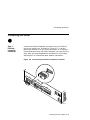
Connecting the Power Cord to the System Unit . . . . . . . .
Factory-Installed Software Label . . . . . . . . . . . . . . . . . . .
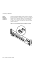
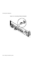
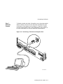
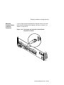
Connecting a Modem . . . . . . . . . . . . . . . . . . . . . . . . . . . .
.
.
.
.
.
.
.
.
.
.
.
.
.
.
.
.
.
.
.
.
.
.
.
.
.
.
.
.
.
.
.
.
.
.
.
.
.
.
.
.
.
.
.
.
.
1–3
2–2
2–4
2–7
2–8
2–9
2–10
2–11
2–12
3–3
3–8
3–9
3–10
3–11
3–12
.
.
.
.
.
.
.
.
.
.
.
.
.
.
.
3–13
3–14
3–15
3–16
3–17
3–12
3–13
3–14
4–1
4–2
4–3
4–4
4–5
4–6
4–7
4–8
4–9
4–10
5–1
5–2
5–3
5–4
5–5
6–1
6–2
6–3
6–4
6–5
6–6
7–1
7–2
7–3
8–1
10–1
11–1
11–2
11–3
11–4
11–5
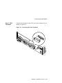
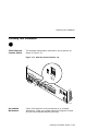
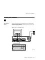
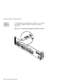
Connecting a Printer to the System . . . . . . . . . . . . . . . . .
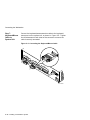
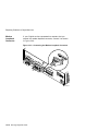
Alternate Console Switch: Up . . . . . . . . . . . . . . . . . . . . .
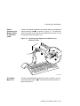
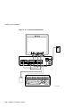
A Connected Workstation . . . . . . . . . . . . . . . . . . . . . . . . .
Parts Used to Install Your Server . . . . . . . . . . . . . . . . . .
Connecting the Ethernet Loopback Connector . . . . . . . . .
Connecting the SCSI Terminator . . . . . . . . . . . . . . . . . . .
Connecting a Terminal to the System Unit . . . . . . . . . . .
Checking the Alternate Console Switch . . . . . . . . . . . . . .
Factory-Installed Software Label . . . . . . . . . . . . . . . . . . .
Connecting the Power Cord to the System Unit . . . . . . . .
Connecting a Modem . . . . . . . . . . . . . . . . . . . . . . . . . . . .
Connecting a Printer to the System . . . . . . . . . . . . . . . . .
A Connected Server . . . . . . . . . . . . . . . . . . . . . . . . . . . . .
Connecting to an AUI Ethernet Network . . . . . . . . . . . . .
Connecting a 10BASE-T Network Cable . . . . . . . . . . . . .
Connecting the AUI Ethernet Cable to the DECXM
Transceiver . . . . . . . . . . . . . . . . . . . . . . . . . . . . . . . . . . .
Connecting the ThinWire Cables and T-Connector to the
DECXM Transceiver . . . . . . . . . . . . . . . . . . . . . . . . . . . .
Terminating the Ethernet Connection . . . . . . . . . . . . . . .
Turning On the System . . . . . . . . . . . . . . . . . . . . . . . . . .
Startup Display . . . . . . . . . . . . . . . . . . . . . . . . . . . . . . . .
OpenVMS AXP Initial Startup Display . . . . . . . . . . . . . .
OpenVMS AXP DECwindows Motif Start Session Screen
DEC OSF/1 AXP Initial Startup Display . . . . . . . . . . . . .
DEC OSF/1 AXP DECwindows Motif Start Session
Screen . . . . . . . . . . . . . . . . . . . . . . . . . . . . . . . . . . . . . . .
Turning Off the System Unit . . . . . . . . . . . . . . . . . . . . .
Pressing the Halt Button . . . . . . . . . . . . . . . . . . . . . . . . .
System Halt Message . . . . . . . . . . . . . . . . . . . . . . . . . . . .
Removing/Replacing the Mouse Cover Plate . . . . . . . . . .
The show device Display . . . . . . . . . . . . . . . . . . . . . . . . .
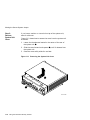
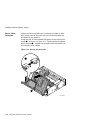
Removing the System Unit Cover . . . . . . . . . . . . . . . . . .
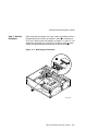
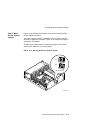
Releasing the Driveplate . . . . . . . . . . . . . . . . . . . . . . . . .
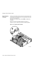
Moving the Driveplate . . . . . . . . . . . . . . . . . . . . . . . . . . .
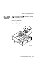
Moving the Secure System Jumper . . . . . . . . . . . . . . . . .
Replacing the Driveplate . . . . . . . . . . . . . . . . . . . . . . . . .
.
.
.
.
.
.
.
.
.
.
.
.
.
.
.
.
.
.
.
.
.
.
.
.
.
.
.
.
.
.
.
.
.
.
.
.
.
.
.
.
.
.
.
.
.
3–18
3–19
3–20
4–3
4–5
4–6
4–7
4–8
4–9
4–10
4–11
4–12
4–13
5–5
5–7
...
5–9
.
.
.
.
.
.
.
.
.
.
.
.
.
.
.
.
.
.
.
.
.
5–10
5–11
6–5
6–6
6–9
6–10
6–11
.
.
.
.
.
.
.
.
.
.
.
.
.
.
.
.
.
.
.
.
.
.
.
.
.
.
.
.
.
.
.
.
.
6–12
7–4
7–6
7–7
8–5
10–8
11–6
11–7
11–8
11–9
11–10
ix
11–6
11–7
12–1
12–2
13–1
13–2
13–3
13–4
13–5
13–6
13–7
14–1
14–2
14–3
14–4
14–5
14–6
14–7
14–8
14–9
B–1
B–2
B–3
B–4
B–5
B–6
B–7
B–8
D–1
x
Replacing the Drive Cable and Driveplate Thumbscrews .
Replacing the Cover . . . . . . . . . . . . . . . . . . . . . . . . . . . . .
Attaching a Device to the Alternate Console/
Printer Port . . . . . . . . . . . . . . . . . . . . . . . . . . . . . . . . . . .
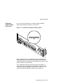
Changing the Alternate Console Switch . . . . . . . . . . . . . .
Power Indicator Light . . . . . . . . . . . . . . . . . . . . . . . . . . .
Position of Diagnostic Display Lights . . . . . . . . . . . . . . . .
Startup Display with Error . . . . . . . . . . . . . . . . . . . . . . .
Configuration Display with Error . . . . . . . . . . . . . . . . . . .
The show device Display . . . . . . . . . . . . . . . . . . . . . . . . .
The show error Display . . . . . . . . . . . . . . . . . . . . . . . . . .
The show memory Display . . . . . . . . . . . . . . . . . . . . . . .
SCC Diagnostic Test Display . . . . . . . . . . . . . . . . . . . . . .
SCC Test Display with Error . . . . . . . . . . . . . . . . . . . . . .
Initializing Your System . . . . . . . . . . . . . . . . . . . . . . . . . .
Initializing the System with the SCC Test . . . . . . . . . . . .
Position of Diagnostic Display Lights . . . . . . . . . . . . . . . .
Serial and Model Numbers . . . . . . . . . . . . . . . . . . . . . . .
Connecting the 10BASE-T Loopback Connector . . . . . . . .
Connecting the Alternate Console/Printer Loopback
Connector . . . . . . . . . . . . . . . . . . . . . . . . . . . . . . . . . . . . .
Connecting the Modem Loopback Connector . . . . . . . . . .
Alternate Console/Printer Port . . . . . . . . . . . . . . . . . . . . .
Synchronous/Asynchronous Communications Port . . . . . .
External SCSI Port . . . . . . . . . . . . . . . . . . . . . . . . . . . . .
Keyboard/Mouse or Tablet Port . . . . . . . . . . . . . . . . . . . .
AUI Ethernet Port . . . . . . . . . . . . . . . . . . . . . . . . . . . . . .
ISDN Port . . . . . . . . . . . . . . . . . . . . . . . . . . . . . . . . . . . .
10BASE-T Port . . . . . . . . . . . . . . . . . . . . . . . . . . . . . . . .
Audio Port . . . . . . . . . . . . . . . . . . . . . . . . . . . . . . . . . . . .
Connector Pin Layout . . . . . . . . . . . . . . . . . . . . . . . . . . .
...
...
11–11
11–12
.
.
.
.
.
.
.
.
.
.
.
.
.
.
.
.
.
.
.
.
.
.
.
.
.
.
.
.
.
.
.
.
.
.
.
.
.
.
.
.
.
.
.
.
.
.
.
.
12–4
12–5
13–6
13–7
13–9
13–13
13–14
13–17
13–19
14–6
14–7
14–9
14–10
14–11
14–14
14–16
.
.
.
.
.
.
.
.
.
.
.
.
.
.
.
.
.
.
.
.
.
.
.
.
.
.
.
.
.
.
.
.
.
14–17
14–18
B–2
B–3
B–5
B–7
B–8
B–10
B–11
B–12
D–6
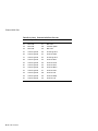
Tables
1
2–1
2–2
2–3
2–4
2–5
2–6
3–1
3–2
3–3
3–4
4–1
4–2
5–1
5–2
5–3
5–4
5–5
6–1
6–2
6–3
6–4
6–5
6–6
7–1
7–2
7–3
7–4
8–1
9–1
9–2
9–3
9–4
9–5
Parts Description . . . . . . . . . . . . . . . . . . . . . . . . . . . . . . .
Requirements for System Location . . . . . . . . . . . . . . . . . .
Hazards to Avoid . . . . . . . . . . . . . . . . . . . . . . . . . . . . . . .
Positioning Your System Components . . . . . . . . . . . . . . .
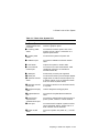
Front of the System Unit . . . . . . . . . . . . . . . . . . . . . . . . .
Back of the System Unit . . . . . . . . . . . . . . . . . . . . . . . . .
Where to Go Next . . . . . . . . . . . . . . . . . . . . . . . . . . . . . .
Steps to Install Your DEC 3000 Model 600/700 AXP
Workstation . . . . . . . . . . . . . . . . . . . . . . . . . . . . . . . . . . .
Making Monitor Connections . . . . . . . . . . . . . . . . . . . . . .
Connecting the Monitor Cables to the Monitor . . . . . . . .
Where to Go Next . . . . . . . . . . . . . . . . . . . . . . . . . . . . . .
Steps to Install Your DEC 3000 Model 600S AXP Server .
Where to Go Next . . . . . . . . . . . . . . . . . . . . . . . . . . . . . .
Required Network Cables . . . . . . . . . . . . . . . . . . . . . . . .
Steps for Connecting an AUI Ethernet Network . . . . . . .
Steps for Connecting a ThinWire Ethernet Network . . . .
DECXM Documentation . . . . . . . . . . . . . . . . . . . . . . . . . .
Network Settings . . . . . . . . . . . . . . . . . . . . . . . . . . . . . . .
Steps for Starting a Workstation . . . . . . . . . . . . . . . . . .
Steps for Starting a Server . . . . . . . . . . . . . . . . . . . . . . .
Startup Display Information . . . . . . . . . . . . . . . . . . . . . .
Factory-Installed Software Documentation . . . . . . . . . . .
Start the Operating System . . . . . . . . . . . . . . . . . . . . . . .
Where to Go Next . . . . . . . . . . . . . . . . . . . . . . . . . . . . . .
Current System Status . . . . . . . . . . . . . . . . . . . . . . . . . .
Steps to Shutting Down Your System . . . . . . . . . . . . . . .
Operating System Shutdown Procedure . . . . . . . . . . . . . .
Halting the Operating Systems . . . . . . . . . . . . . . . . . . . .
Steps for Cleaning the Mouse . . . . . . . . . . . . . . . . . . . . .
Supported Keys and Control Characters . . . . . . . . . . . . .
Basic Console Commands . . . . . . . . . . . . . . . . . . . . . . . . .
Advanced Console Commands . . . . . . . . . . . . . . . . . . . . .
Boot Command Parameters/Qualifiers . . . . . . . . . . . . . . .
Device Naming Conventions . . . . . . . . . . . . . . . . . . . . . .
.
.
.
.
.
.
.
.
.
.
.
.
.
.
.
.
.
.
.
.
.
xv
2–3
2–3
2–5
2–11
2–13
2–15
.
.
.
.
.
.
.
.
.
.
.
.
.
.
.
.
.
.
.
.
.
.
.
.
.
.
.
.
.
.
.
.
.
.
.
.
.
.
.
.
.
.
.
.
.
.
.
.
.
.
.
.
.
.
.
.
.
.
.
.
.
.
.
.
.
.
.
.
.
.
.
.
.
.
.
.
.
.
.
.
.
3–4
3–6
3–7
3–21
4–4
4–14
5–3
5–4
5–8
5–11
5–12
6–4
6–4
6–7
6–8
6–13
6–14
7–2
7–3
7–3
7–5
8–5
9–5
9–7
9–8
9–9
9–10
xi
9–6
10–1
10–2
10–3
11–1
11–2
11–3
11–4
11–5
11–6
11–7
11–8
12–1
12–2
12–3
13–1
13–2
13–3
13–4
13–5
13–6
13–7
13–8
13–9
13–10
13–11
13–12
13–13
13–14
13–15
13–16
13–17
13–18
13–19
13–20
13–21
14–1
xii
Diagnostic Tests . . . . . . . . . . . . . . . . . . . . . . . . . . . . . .
Environment Variables . . . . . . . . . . . . . . . . . . . . . . . . .
Parameters for Setting Startup Action . . . . . . . . . . . . .
Device Naming Conventions . . . . . . . . . . . . . . . . . . . .
Console Command Access . . . . . . . . . . . . . . . . . . . . . .
Steps to Making the System Secure . . . . . . . . . . . . . . .
Steps to Moving Secure System Jumper . . . . . . . . . . .
Entering a Password . . . . . . . . . . . . . . . . . . . . . . . . . .
Enabling the Secure Environment Variable . . . . . . . . .
Entering a Login Command . . . . . . . . . . . . . . . . . . . . .
Steps to Access System . . . . . . . . . . . . . . . . . . . . . . . .
Changing a Password . . . . . . . . . . . . . . . . . . . . . . . . . .
Current System Status . . . . . . . . . . . . . . . . . . . . . . . .
Alternate Console/Printer Port Parameters . . . . . . . . .
Using the Alternate Console . . . . . . . . . . . . . . . . . . . .
How to Identify a Problem . . . . . . . . . . . . . . . . . . . . . .
Steps to Resolving Problems . . . . . . . . . . . . . . . . . . . .
Type of Problem . . . . . . . . . . . . . . . . . . . . . . . . . . . . . .
Power Indicator Light Failure . . . . . . . . . . . . . . . . . . .
Diagnostic Lights Display Error . . . . . . . . . . . . . . . . . .
Missing Startup Display . . . . . . . . . . . . . . . . . . . . . . .
Startup Error Codes . . . . . . . . . . . . . . . . . . . . . . . . . . .
Startup Without Booting . . . . . . . . . . . . . . . . . . . . . . .
Information Provided by the show Console Commands
The show config Display Described . . . . . . . . . . . . . . .
The show device Display Described . . . . . . . . . . . . . . .
System Device Errors . . . . . . . . . . . . . . . . . . . . . . . . .
Error Message Elements . . . . . . . . . . . . . . . . . . . . . . .
Monitor Display Problems . . . . . . . . . . . . . . . . . . . . . .
Monitor Display Problems . . . . . . . . . . . . . . . . . . . . . .
Mouse Problems . . . . . . . . . . . . . . . . . . . . . . . . . . . . . .
Keyboard Problems . . . . . . . . . . . . . . . . . . . . . . . . . . .
Installed Disk Drive Problems . . . . . . . . . . . . . . . . . . .
Installed Software Problems . . . . . . . . . . . . . . . . . . . .
Resolving NI Network Errors . . . . . . . . . . . . . . . . . . .
Problems When Booting from the Network . . . . . . . . .
Steps to Diagnostic Tests . . . . . . . . . . . . . . . . . . . . . . .
.
.
.
.
.
.
.
.
.
.
.
.
.
.
.
.
.
.
.
.
.
.
.
.
.
.
.
.
.
.
.
.
.
.
.
.
.
.
.
.
.
.
.
.
.
.
.
.
.
.
.
.
.
.
.
.
.
.
.
.
.
.
.
.
.
.
.
.
.
.
.
.
.
.
.
.
.
.
.
.
.
.
.
.
.
.
.
.
.
.
.
.
.
.
.
.
.
.
.
.
.
.
.
.
.
.
.
.
.
.
.
.
.
.
.
.
.
.
.
.
.
.
.
.
.
.
.
.
.
.
.
.
.
.
.
.
.
.
.
.
.
.
.
.
.
.
.
.
.
.
.
.
.
.
.
.
.
.
.
.
.
.
.
.
.
.
.
.
.
.
.
.
.
.
.
.
.
.
.
.
.
.
.
.
.
9–18
10–3
10–5
10–7
11–3
11–4
11–5
11–13
11–14
11–15
11–16
11–17
12–2
12–2
12–3
13–2
13–3
13–5
13–6
13–8
13–8
13–10
13–11
13–12
13–13
13–15
13–17
13–18
13–21
13–22
13–23
13–23
13–24
13–25
13–26
13–27
14–3
14–2
14–3
14–4
14–5
A–1
A–2
A–3
A–4
A–5
B–1
B–2
B–3
B–4
B–5
B–6
B–7
B–8
C–1
C–2
C–3
C–4
D–1
D–2
D–3
D–4
D–5
Diagnostic Tests . . . . . . . . . . . . . . . . . . . . . . . . . . . . . . .
TURBOchannel Tests . . . . . . . . . . . . . . . . . . . . . . . . . . .
Diagnostic Display Lights . . . . . . . . . . . . . . . . . . . . . . .
Telephone Numbers of Digital Support Centers . . . . . . .
System Unit Dimensions - Desktop . . . . . . . . . . . . . . . .
System Electrical Specifications . . . . . . . . . . . . . . . . . . .
System Specifications . . . . . . . . . . . . . . . . . . . . . . . . . .
System Environmental Specifications . . . . . . . . . . . . . .
Power Cord Part Numbers . . . . . . . . . . . . . . . . . . . . . . .
Alternate Console/Printer Port Pin-outs . . . . . . . . . . . . .
Synchronous/Asynchronous Communications Port
Pin-outs . . . . . . . . . . . . . . . . . . . . . . . . . . . . . . . . . . . . .
External SCSI Port Pin-outs . . . . . . . . . . . . . . . . . . . . .
Keyboard/Mouse or Tablet Port Pin-outs . . . . . . . . . . . .
AUI Ethernet Port Pin-outs . . . . . . . . . . . . . . . . . . . . . .
ISDN Port Pin-outs . . . . . . . . . . . . . . . . . . . . . . . . . . . .
10BASE-T Port Pin-outs . . . . . . . . . . . . . . . . . . . . . . . .
Audio Port Pin-outs . . . . . . . . . . . . . . . . . . . . . . . . . . . .
Associated Printed Documents . . . . . . . . . . . . . . . . . . . .
OpenVMS AXP Operating System Documents . . . . . . . .
User Documentation, QA–MT4AB–GZ . . . . . . . . . . . . . .
Server Documentation Kit, QA–MT4AL–GZ . . . . . . . . .
BABT-Approved Service Specifications for the 54-21813
Module for UK Compliance . . . . . . . . . . . . . . . . . . . . . .
Module Power . . . . . . . . . . . . . . . . . . . . . . . . . . . . . . . .
Clearance and Creepage Distances . . . . . . . . . . . . . . . .
Connector Pin-Outs Described . . . . . . . . . . . . . . . . . . . .
Cables Supported by the 54-21813 Module . . . . . . . . . .
.
.
.
.
.
.
.
.
.
.
.
.
.
.
.
.
.
.
.
.
.
.
.
.
.
.
.
.
.
.
.
.
.
.
.
.
.
.
.
.
14–5
14–8
14–12
14–15
A–2
A–2
A–3
A–4
A–6
B–2
.
.
.
.
.
.
.
.
.
.
.
.
.
.
.
.
.
.
.
.
.
.
.
.
.
.
.
.
.
.
.
.
.
.
.
.
.
.
.
.
.
.
.
.
B–3
B–5
B–7
B–9
B–10
B–11
B–12
C–2
C–3
C–4
C–5
.
.
.
.
.
.
.
.
.
.
.
.
.
.
.
.
.
.
.
.
D–2
D–3
D–5
D–6
D–7
xiii
Preface
Purpose of
This Guide
This guide is intended for all users of the DEC 3000 Model 600/
600S/700 AXP system. It describes how to install and operate the
system. To install options in the system, refer to the DEC 3000
Model 600/600S/700 AXP Options Guide and the documentation
for the specific options.
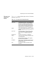
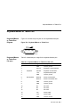
Structure of
This Guide
This guide consists of 14 chapters, 4 appendixes, a glossary, and
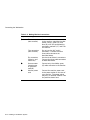
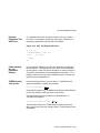
an index, and is organized into three parts as Table 1 describes.
Table 1 Parts Description
Part
Title
Description
I
Basic Operations
Chapters in Part I describe
basic operations for using your
workstation or server system,
including installing, turning on, and
maintaining your system. These
chapters are for all DEC 3000
Model 600/600S/700 AXP system
users.
(continued on next page)
xv
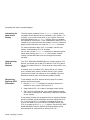
Table 1 (Cont.) Parts Description
Conventions
Part
Title
Description
II
Advanced
Operations
Chapters in Part II describe
advanced operations for your
system, including use of console
commands and the alternate console
feature. These chapters are for
users who understand or want
to learn about advanced system
operations.
III
Troubleshooting
Chapters in Part III describe what
to do in the event of a system
problem. These chapters are
applicable only if your system is
not working properly or if it is
displaying errors.
IV
Appendixes
The appendixes in Part IV provide
information such as specifications
and port pinouts.
The following conventions are used in this guide:
Convention
Description
RZ2x
RZ2x refers to the RZ-series fixed disk
drives.
Return
A key name in a box indicates that you
press a named key on the keyboard.
Ctrl/x
A sequence such as Ctrl/x indicates that
you must hold down the key labeled
Ctrl while you press another key.
show config
Lowercase type in this format indicates
a command that you must enter exactly
as shown. For example:
>>> show config
xvi
Return
Convention
Description
variable
Lowercase italics indicate a variable
value that you must provide. For
example:
>>> set variable
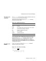
Task Symbols
Return
CAUTION
Cautions provide information to prevent
damage to equipment or software. Read
these carefully.
WARNING
Warnings contain information to
prevent personal injury. Read these
carefully.
All of the tasks described in this guide have been assigned a
symbol indicating the level of difficulty in completing the task.
The task symbols that appear in the margin next to the task
should be used as a guide to help you decide whether you wish to
complete the task, or request help.
Different tasks within a category may require different levels
of expertise. For instance, one intermediate task may require
software expertise, while another intermediate task may require
hardware expertise. Check the Before You Begin section at the
beginning of most chapters, for the specific kind of experience
required to complete a task. This section will be identified by the
information icon, explained below.
i
Information
This icon indicates a section that contains important background
information that will help you to perform required tasks and
operate your system correctly.
xvii
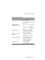
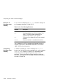
Task
Categories
The tasks fall into three categories indicated by three symbols:
Basic Task
This task does not require any specific experience to complete.
Intermediate Task
Some specific experience is required to complete this task.
Advanced Task
Specific experience is highly desirable to complete this task.
xviii
Part I
Basic Operations
Part I provides an overview of the DEC 3000 Model 600/600S/700
AXP system and its configurations. It also describes how to
install the system and how to perform basic operations.
This section includes the following chapters.
Chapter
Title
1
Introduction to Your System
2
Preparing to Install Your System
3
Installing a Workstation System
4
Installing a Server System
5
Connecting Your System to a Network
6
Starting Up Your System
7
Turning Off Your System
8
Maintaining Your System
1
Introduction to Your System
Chapter Overview
Introduction
The DEC 3000 Model 600/600S/700 AXP systems are highperformance, desktop units that provide all the advantages
of a 64-bit computing environment and the choice of different
operating systems. These systems incorporate Digital’s DECchip
RISC microprocessors, which are part of the Digital Alpha AXP
architecture.
In This Chapter
This chapter introduces you to your system, gives you an idea of
its design and special capabilities, and describes the available
options.
This chapter covers the following information:
•
System Configurations
•
Overview of the System
•
Operating Systems
•
Software Product Descriptions (SPD)
•
Graphics Capabilities
•
Integrated Services Digital Network (ISDN)
•
Audio Capabilities
•
Available Options
Introduction to Your System 1–1
System Configurations
System Configurations
Two System
Configurations
The system is available in two configurations:
•
A workstation, Model 600 or 700
•
A server system, Model 600S
This guide describes the installation and set up of both
configurations, along with information common to both
configurations.
Workstation
Configuration
Your workstation is preconfigured with a graphics module, and
is shipped with a monitor. Chapter 3 describes how to install a
workstation system.
Server
Configuration
Your server system is not preconfigured with a graphics module,
nor is it shipped with a monitor. Chapter 4 describes how to
install a server system.
1–2 Introduction to Your System
Overview of the System
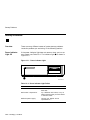
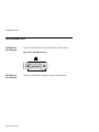
Overview of the System
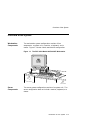
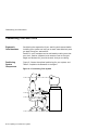
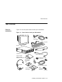
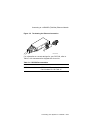
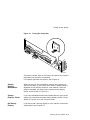
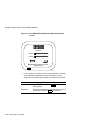
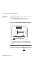
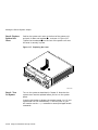
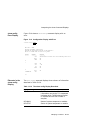
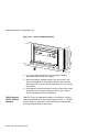
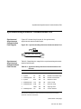
Workstation
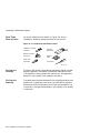
Components
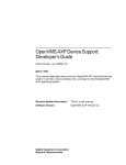
The workstation system configuration consists of four
components: a system unit, a monitor, a keyboard, and a
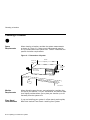
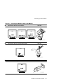
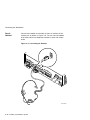
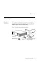
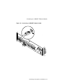
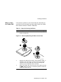
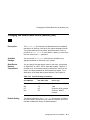
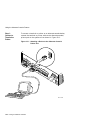
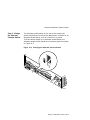
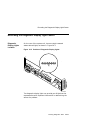
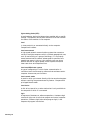
mouse. Figure 1–1 shows a basic workstation configuration.
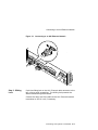
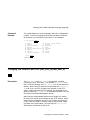
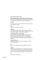
Figure 1–1 The DEC 3000 Model 600/700 AXP Workstation
MLO-010356
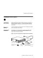
Server
Components
The server system configuration consists of a system unit. The
server configuration does not include a monitor, keyboard, or a
mouse.
Introduction to Your System 1–3
Overview of the System
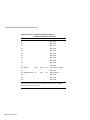
System
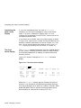
Highlights
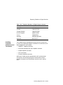
The DEC 3000 Model 600/600S/700 AXP system provides the
following special features:
This feature...
Provides...
Alpha RISC 64-bit
architecture
Significant performance advantages.
Flexible memory architecture
Expandable memory from 32 to
512 megabytes using 4-, 8-, 16- or
32-megabyte single inline memory
modules (SIMMs).
Internal and external options
Increased storage capacity, graphics,
communications, and other capabilities
to your system.
SCSI
SCSI-1 (slow SCSI) allows transmission
rates up to 5 megabytes a second;
SCSI-2 (fast SCSI) allows transmission
rates up to 10 megabytes a second.
An AUI Ethernet port
Connection to an AUI Ethernet
(Thickwire) network.
A 10BASE-T Ethernet
network port
Connection to a twisted-pair network.
ISDN network port
An industry-standard port for an ISDN
network connection.
Three TURBOchannel slots
Access to high-performance module
interconnect technology that allows a
variety of options, including graphics,
multimedia, communications and other
third-party options.
Secure system feature
Additional system security for limited
access to privileged console functions.
Audio technology
Built-in telephone-quality audio input
and output capabilities.
Two supported operating
systems
Support for OpenVMS AXP or DEC
OSF/1 AXP operating systems.
Multihead support
Capability to support multiple graphics
devices. The number of graphics
devices supported is operating systemdependent.
1–4 Introduction to Your System
Operating Systems
Operating Systems
Choice of
Operating
Systems
Digital’s Alpha AXP architecture allows you to choose from
various operating systems. The operating system is the core
software installed on your system that allows you to install and
run applications.
The following operating systems are supported for use on your
workstation or server:
•
OpenVMS AXP
•
DEC OSF/1 AXP
OpenVMS AXP
Operating
System
The OpenVMS AXP operating system is a general purpose,
multiuser operating system that can be used in many different
environments for a wide variety of applications.
Features of
OpenVMS AXP
The OpenVMS AXP operating system promotes ease of use
and improved programming productivity, and facilitates system
management.
OpenVMS AXP offers a combination of commercial features and
open system benefits, including the following capabilities:
•
Integrated networking
•
System security
•
Distributed computing
•
Windowing capabilities
Additionally, OpenVMS AXP supports a large number of
industry standards to facilitate application portability and
interoperability.
Introduction to Your System 1–5
Operating Systems
DEC OSF/1
AXP Operating
System
The DEC OSF/1 AXP operating system is Digital Equipment
Corporation’s implementation of the Open Software Foundation
(OSF) operating system components and Motif graphical user
interface and programming environment.
Description
of DEC OSF/1
AXP
DEC OSF/1 AXP is compliant with the OSF Application
Environment Specification (AES), which specifies the interface
to support portable applications designed to run on a variety of
hardware platforms.
In addition, the DEC OSF/1 operating system complies with the
following standards and industry specifications:
DEC OSF/1 AXP
Architecture
•
FIPS 151-1
•
POSIX (IEEE Std. 1003.1-1988)
•
XPG3 BASE branding
•
XTI
•
AT&T System V Interface Definition (SVID) Issue 2 (Base
System and Kernel Extensions)
The DEC OSF/1 AXP operating system is an advanced kernel
architecture based on Carnegie Mellon University’s Mach
V2.5 kernel design with components from Berkeley Software
Distribution 4.3 (BSD) and other sources. DEC OSF/1 AXP
provides numerous features to assist application programmers
in developing applications that use shared libraries, multithread
support, and memory mapped files.
To ensure a high level of binary compatibility with the ULTRIX
operating system, the DEC OSF/1 AXP operating system is
compatible with the Berkeley 4.3 programming interfaces.
1–6 Introduction to Your System
Software Product Descriptions (SPD)
Software Product Descriptions (SPD)
SPD
Description
The Software Product Description (SPD) is the official defining
document for software products licensed by Digital Equipment
Corporation, including third-party products licensed by Digital.
An SPD describes all important functional characteristics of the
software. The terms and conditions under which the corporation
sells and licenses its software products identify SPDs as the
documents that specify Digital’s obligation under software
warranty.
SPDs also describe a software product’s system environment
and identify required and optional hardware and software. All
information contained in the SPD is valid in the international
marketplace.
For more information on the SPD for your operating system,
please contact your Digital sales representative.
You May Have
Factory-Installed
Software
If your system is shipped with an installed internal fixed disk
drive, the operating system is factory-installed on the disk.
Depending on which operating system you ordered, your system
will start with the OpenVMS AXP Factory Installed Software
(FIS) procedure, or the DEC OSF/1 AXP Factory-Installed
Software (FIS) Startup Procedure.
Chapter 6 describes how to start your system.
Introduction to Your System 1–7
Graphics Capabilities
Graphics Capabilities
Graphics
Options
Workstation graphics and multimedia options are available via
the use of a TURBOchannel graphics module. All preconfigured
DEC 3000 Model 600/700 AXP workstations are shipped with
a TURBOchannel graphics module installed. TURBOchannelbased graphics provide a wide variety of Digital and third-party
graphics options.
DEC Open3D
Software
Three dimensional (3D) graphics support is provided by the
DEC Open3D software which is included in Factory-Installed
Software (FIS) systems. If you do not have FIS and need 3D
graphics support, contact your Digital sales representative for
availability of the Open3D software as a layered product for both
the OpenVMS AXP and the DEC OSF/1 AXP operating systems.
Multiple
Graphic
Devices
Your system is capable of supporting multiple 2D graphics
devices. Refer to the SPD for a list of supported graphics
options.
1–8 Introduction to Your System
Integrated Services Digital Network (ISDN)
Integrated Services Digital Network (ISDN)
Note: ISDN Not
Yet Available
Though your system can provide ISDN capabilities, they are not
yet agency approved and available for your system. Currently,
a plug has been placed in the ISDN port pending approval of
ISDN licenses. Once agency approval of ISDN for the DEC 3000
Model 600/600S/700 AXP system has been granted, you will be
contacted by your Digital sales representative to inform you of
the ISDN certification. At that point, you must remove the plug
from the ISDN port before connecting to the ISDN network.
The following information explains the ISDN capabilities for
your system pending license approval.
Australian ISDN
Connections
The ISDN interface in this equipment has not completed
Australian ISDN network connection certification testing and
as such does not have an AUSTEL permit for connection. In
Australia it is an offence to connect non-permitted devices to a
public telecommunications network and may attract a fine of up
to $12,000.
Plug in ISDN
Connector
Your system is shipped with a foam plug inserted in the ISDN
connector so that the port is inaccessible. Before using the port
when ISDN is available, remove the foam plug carefully so that
you do not damage any of the port connections.
ISDN
Capabilities
ISDN is a digital telecommunications network, providing
connectivity for voice and data applications.
Your workstation includes an ISDN Basic Rate S/T interface,
which includes:
Use of ISDN B
Channels
•
two 64-kilobits-per-second B channels
•
one 16-kilobits-per-second D channel
The B channels can be used for digitized voice, circuit-switched
data transmission at up to 64 kilobits per second, or for
packet-switched data transmission.
Introduction to Your System 1–9
Integrated Services Digital Network (ISDN)
Use of ISDN D
Channels
The D channel uses a protocol standardized by the International
Telegraph and Telephone Consultative Committee (CCITT) for
setting up D Channel connections. The D channel can also be
used for low-speed packet transmission.
Audio Capabilities
Audio Overview
The system features telephone-quality audio input and output
capabilities. Port pinouts for the audio jack on the system unit
are provided in Appendix B.
DECsound
Application
Systems shipped with the OpenVMS AXP operating system
include the DECsound application as part of the DECwindows
Motif software package. DECsound is an easy-to-use software
application that lets you play back recorded messages, record
audio messages, mail recorded messages, and include recorded
messages in compound documents.
1–10 Introduction to Your System
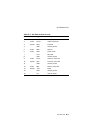
Available Options
Available Options
Internal
Options
You can install the following hardware options inside the system
unit:
Option
Capabilities Provided
Two half-height
RZ2x-series fixed
disk drives
Additional storage.
One 5¼-inch or one
3½-inch removable
media device (RMD)
Additional data storage on any of the
following devices: diskette drive, compact
disc drive, and tape drive.
Up to 512 megabytes
of total memory
Increased performance.
Up to three
TURBOchannel
modules
A variety of TURBOchannel options,
including 2D and 3D graphics options.
(TURBOchannel options require from one
to three TURBOchannel slots inside the
system unit.)
Introduction to Your System 1–11
Available Options
TURBOchannel
Options
There are a total of three TURBOchannel option slots on your
system. Preconfigured workstation systems use one or more slots
for a graphics option, depending on the TURBOchannel option
installed.
Installing
Internal
Options
For information about adding TURBOchannel and other internal
options to your system, see the DEC 3000 Model 600/600S/700
AXP Options Guide.
External
Options
You can add one or more of the following external options to your
system:
•
A printer such as a color or PostScript laser printer
•
A modem
•
A puck or stylus tablet
•
A diskette drive
•
A DAT (digital audio tape) drive
•
A TURBOchannel extender box
•
An expansion box
Adding
External
Options
For more information about external options and how to add
them to your server or workstation, refer to the documentation
that comes with the specific options.
Ordering
Options
Contact your Digital sales representative for more information
about ordering system options.
1–12 Introduction to Your System
2
Preparing to Install Your System
Chapter Overview
Introduction
Before you install your system, you need to prepare your site and
familiarize yourself with your system hardware.
In This Chapter
This chapter covers the following topics:
•
Choosing a Location
•
Customizing Your Work Area
•
Unpacking a Workstation System
•
Unpacking a Server System
•
A Closer Look at Your System
•
Where to Go Next
Preparing to Install Your System 2–1
Choosing a Location
Choosing a Location
Space
Requirements
When choosing a location, consider the system measurements
as shown in Figure 2–1. Make sure to leave enough room for
air to circulate around the system unit. Table 2–1 describes the
specific circulation requirements.
Figure 2–1 Dimensions of System
44.5 cm
(17.5 in)
53 cm
(20 in)
12.7 cm
(5 in)
MLO-009191
Monitor
Requirements
When allocating space for your new workstation, consider also
the size of your monitor. For your convenience, the monitor cable
that Digital provides allows you to place your monitor up to 10
feet away from the system unit.
Floor Stand
Considerations
If you are installing your system in a floor stand, see the guide,
BA47X-AA Vertical Floor Stand: Installing Your System.
2–2 Preparing to Install Your System
Choosing a Location
Location
Requirements
Choose a location for your system that meets the requirements
listed in Table 2–1:
Table 2–1 Requirements for System Location
Requirement
Explanation
Dedicated power
source with isolated
ground
Power source must be 110–120 VAC or 220–240 VAC. Specific power
requirements and electrical specifications are provided in Appendix A.
Moderate
temperature
Hardware operating conditions for the workstation or server range from
10°C to 35°C (50°F to 95°F).
Relative humidity
Relative humidity should range between 10 percent and 90 percent.
Ample circulation
Do not place your system near a heat source. Provide a minimum of 7.6
centimeters (3 inches) of clearance on all sides of the system unit. This
allows air to circulate around the system to prevent excess heat and to
keep the system air vents clean.
Working room
Leave enough room on your desktop for your monitor, keyboard, mouse
pad, and any papers and materials that you may need.
What to Avoid
in a Location
When choosing a location for your workstation, try to avoid the
hazards listed in Table 2–2:
Table 2–2 Hazards to Avoid
Hazard
How to Avoid
Dust and dirt
Do not position the system unit directly on the floor. Dust and dirt
damage system components.
Heat and sunlight
Do not place your system in direct sunlight, close to a heater, or near a
photocopier.
Unstable location
Place your system on a desktop or table that is steady and strong enough
to support the system unit and the monitor. Your new workstation
weighs approximately 20.4 kilograms (45 pounds). A monitor can weigh
up to 34 kilograms (75 pounds).
Preparing to Install Your System 2–3
Customizing Your Work Area
Customizing Your Work Area
Ergonomic
Considerations
Considering the ergonomics of your working environment before
installing your system can help you to work more effectively once
you begin using your workstation.
Comfort in your workplace can be achieved by making sure that
your chair, monitor, keyboard, and mouse are set at the right
height and distance for you and the work that you are doing.
Positioning
System
Components
Figure 2–2 shows the optimal positioning for your system, and
Table 2–3 explains the elements in the figure.
Figure 2–2 Positioning Your System
9
8
7
5
6
4
3
2
1
MLO-010354
2–4 Preparing to Install Your System
Customizing Your Work Area
Table 2–3 Positioning Your System Components
Adjust your chair so that...
!
"
#
$
Your feet are flat on the floor–use a footrest if needed.
Your legs form a right angle to the floor.
The backs of your knees are free from the seat cushion.
The body weight rests on the spine with support of the
lower back region.
Adjust your monitor and keyboard so that...
%
&
'
Your wrists are straight and supported. Keyboard, mouse,
and mousepad are at elbow height.
Your elbows are close to your sides, with your upper arms
perpendicular to the floor.
You maintain a neutral neck posture (not straining or
tilting up or down) with the top of the video screen no
higher than eye level.
Adjust lighting and monitor so that...
(
)
Light is directed away from the screen to reduce glare.
Look away to distant objects frequently. Use the tilt and
swivel capabilities of your monitor to place it in the most
comfortable position for your own use.
The screen is the correct distance for your vision.
Preparing to Install Your System 2–5
Unpacking a Workstation System
Unpacking a Workstation System
Checking the
Box Contents
Your workstation arrives in two boxes, one for the system unit
and accessories, the other for the monitor.
Before installing your system, check to see that you have all
of the parts shown in Figure 2–3. The parts shown are for
preconfigured systems. If you did not order a preconfigured
system, check your contents list to make sure that what you
ordered has arrived in your shipment.
If Parts Are
Missing
If you are missing any parts for your workstation, contact your
Digital sales representative immediately.
WARNING:
Two People
Required
The system unit and the monitor shipped with your system are
both quite heavy. Digital recommends that two people remove
these items from the shipping boxes, as indicated on the shipping
cartons.
2–6 Preparing to Install Your System
Unpacking a Workstation System
Parts Used for
Installation
The accessory kit for your system includes many parts, some
of which you do not need during system installation. See
Figure 2–3 for the parts you need.
Figure 2–3 Workstation Components and Parts Used for
Installation
Monitor
Video Cable
Keyboard
Monitor
Monitor Power Cord
System Unit
System Power Cord
Owner’s Guide,
Options Guide,
Other Documentation
Ethernet Loopback
Connector
Universal
Strain Relief
Strap
Headset
Keyboard/Mouse Cable
Mouse with
Mousepad
SCSI
Terminator
(optional)
MLO-012922
Preparing to Install Your System 2–7
Unpacking a Workstation System
Save These
Parts for Later
You do not need the parts shown in Figure 2–4 during
installation. However, please save them for future use.
Figure 2–4 Components and Parts to Save
10BASE-T Loopback
Connector
Modem Loopback
Connector
Printer Port
Terminator
Antistatic
Wrist Strap
Network
Label
Screwdriver
MLO-011247
For Users in
Germany
To comply with certain international standards, Digital includes
German regulatory information (sometimes referred to as the
FTZ postcard) in every system and monitor box. Disregard this
material if your system is not located in Germany.
For Users In
Australia
The yellow warning label attached to the shipping container and
system unit is required by the country of Australia for systems
that provide ISDN functionality but are not yet certified for use
in Australia. Disregard these labels if your system is not located
in Australia.
2–8 Preparing to Install Your System
Unpacking a Server System
Unpacking a Server System
Checking the
Box Contents
Before installing your server, check to see that you have all of
the parts shown in Figure 2–5. You can also check to see that
you have all parts listed on the contents list that arrives with
your system.
If Parts Are
Missing
If you are missing any parts for your server, contact your Digital
sales representative immediately.
Parts Used for
Installation
The accessory kit for your system includes many parts, some
of which you do not need during system installation. See
Figure 2–5 for the parts you need.
Figure 2–5 Server Components and Parts Used for Installation
System
Power Cord
System Unit
Ethernet Loopback
Connector
SCSI
Terminator
(optional)
Owner’s Guide, Options Guide,
Other Documentation
MLO-012790
Preparing to Install Your System 2–9
Unpacking a Server System
WARNING:
Two People
Required
The system unit is quite heavy. Digital recommends that two
people remove it from the shipping box, as indicated on the
packing carton.
Save These
Parts for Later
You do not need the parts shown in Figure 2–6 for installation.
Please save them for future use.
Figure 2–6 Components and Parts to Save
10BASE-T Loopback
Connector
Modem Loopback
Connector
Printer Port
Terminator
Antistatic
Wrist Strap
Network
Label
Screwdriver
MLO-011247
For Users In
Germany
To comply with certain international standards, Digital includes
German regulatory information (sometimes referred to as the
FTZ postcard) in every system box. Disregard this material if
your system is not located in Germany.
For Users In
Australia
The yellow warning label attached to the shipping container and
system unit, is required by the country of Australia for systems
that provide ISDN functionality but are not yet certified for use
in Australia. Disregard these labels if your system is not located
in Australia.
2–10 Preparing to Install Your System
A Closer Look at Your System
A Closer Look at Your System
Front of the
System Unit
Take a minute to familiarize yourself with the front of the
system unit, shown in Figure 2–7. Table 2–4 describes the items
shown.
Figure 2–7 Front of System Unit
1
2
3
MLO-009194
Table 2–4 Front of the System Unit
Feature
! Power indicator light
" Pulldown door
# Optional removable media
device slot
Function
When lit, indicates that the system unit
is on.
Flap door covering the system serial
number and part number.
Slot for inserting a compact disc drive,
a diskette drive, or tape drive.
Preparing to Install Your System 2–11
A Closer Look at Your System
Take a minute to familiarize yourself with the ports, switches,
and indicators on the back of the system unit, shown in
Figure 2–8. Table 2–5 explains the functions of these features.
Back of the
System Unit
Figure 2–8 Back of System Unit
1
2
3
0
1
2
4
5
ISDN
S3
6
8
7
10
9
12
11
14
15
16
17
13
MLO-008606
2–12 Preparing to Install Your System
A Closer Look at Your System
Table 2–5 Back of the System Unit
Feature
!, ", and #
TURBOchannel slots
0, 1 and 2
$ Auxiliary power
socket
% System power
socket
& 10BASE-T port
' Halt button
( AUI Ethernet
network port
) ISDN port
+> Audio port
+? Alternate console
switch
+@ Alternate console/
printer port
+A Diagnostic display
lights
+B Keyboard/mouse
port
+C Synchronous
/asynchronous
communications port
+D SCSI port
+E Power On/Off
switch
Function
In this diagram, TURBOchannel slot 0
contains a graphics option.
To connect the monitor power cord so the
monitor will not require a connection to a
separate power outlet.
To connect the system unit power cord.
To connect a 10BASE-T Ethernet network
cable.
To place the system in console mode.
To connect an AUI Ethernet network cable
(sometimes referred to as standard or
Thickwire Ethernet).
Functionality currently not supported.
To connect the audio input and output adapter.
Toggle switch to redirect console output from
a monitor (switch up) to an alternate console
such as a terminal (switch down).
To connect a terminal as an alternate console,
or a printer.
Used for diagnostic testing purposes.
To connect the keyboard/mouse extension
cable.
To connect a communications device such as a
printer, plotter, modem, or console terminal.
To connect Small Computer System Interface
(SCSI) peripheral devices. Either SCSI-1 or
SCSI-2 devices can be connected.
To turn the system unit power on ( | ) and off
(O).
Preparing to Install Your System 2–13
A Closer Look at Your System
System Unit
Symbols
The rear of your system unit has symbols next to most of the
connectors and ports. Following is an explanation of these
symbols.
Halt Button
Press the halt button to put the system into console mode.
Network Interface Port
Insert the cable for a network connection.
ISDN Interface Port
ISDN currently not available.
Handset Jack
Insert a telephone-style handset into this jack to use the audio
input and output features of the system.
Alternate Console Switch
Indicates the alternate console toggle switch that directs console
output to the monitor or to an alternate console, such as a
terminal.
Alternate Console/Printer/Communications Port
Connect an alternate console, such as a terminal or a printer, to
this port. You can also connect a communications device, such as
a modem, here.
Keyboard/Mouse Port
Attach the keyboard/mouse cable assembly to this port.
Diagnostic Display Lights
Indicates the diagnostic display lights on the system unit.
Communications/Printer Port
Connect a communications device, such as a modem, to this port.
You can also connect a printer or terminal to this port.
SCSI Port
Attach a SCSI cable or terminator to this port.
2–14 Preparing to Install Your System
Where to Go Next
Where to Go Next
Determine Your
Next Task
Use Table 2–6 to determine which chapter to read next.
Table 2–6 Where to Go Next
If you...
Go to...
Are installing a workstation
Chapter 3
Are installing a server
Chapter 4
Installed your system using the Setting
Up Your Workstation card or the Setting
Up Your Server card and you want to:
a. Connect to a network
Chapter 5
b. Start up your system
Chapter 6
Preparing to Install Your System 2–15
3
Installing a Workstation System
Chapter Overview
Introduction
If your system is configured as a workstation, see the installation
instructions in this chapter. For a server system, see Chapter 4.
Your workstation is designed to be installed quickly and easily.
The information in this chapter explains how to connect the
cables to the system unit and to the monitor, and how to prepare
the workstation for startup. Starting your workstation is
explained in Chapter 6.
In This Chapter
This chapter covers the following topics:
•
Before You Begin
•
Task Overview
•
Connecting the Workstation
•
Checking Your Installation
•
Where to Go Next
Installing a Workstation System 3–1
Before You Begin
Before You Begin
i
What You
Should Have
Done Already
Before you install your system components, you should have
completed the following tasks:
•
Determined any ergonomic considerations you may have.
•
Chosen a location for your workstation.
•
Unpacked your workstation.
•
Familiarized yourself with the ports and controls on the rear
of the system unit.
If you have not performed all of these tasks, do so now. They are
covered in Chapter 2.
What You
Should Know
Beforehand
Note that:
•
Installing your system requires little or no previous
knowledge of computer systems. Connecting your
workstation should take about 15 minutes.
•
This chapter covers connecting your system as a standalone
workstation. You may connect your workstation to a network
with a few minor adjustments to the procedures in this
chapter. Chapter 5 explains how to connect to a network.
•
The accessory kit shipped with your workstation includes
parts that you do not need during installation. Save any
terminators or additional parts in case you need them later.
3–2 Installing a Workstation System
Task Overview
Task Overview
Parts for
Installation
Figure 3–1 lists the parts used to install your workstation.
Figure 3–1 Parts Used to Install your Workstation
Monitor
Video Cable
Keyboard
Monitor
Monitor Power Cord
System Unit
System Power Cord
Owner’s Guide,
Options Guide,
Other Documentation
Ethernet Loopback
Connector
Universal
Strain Relief
Strap
Headset
Keyboard/Mouse Cable
Mouse with
Mousepad
SCSI
Terminator
(optional)
MLO-012922
Installing a Workstation System 3–3
Task Overview
Installation
Steps
Table 3–1 gives an overview of the steps involved in installing
your workstation system components.
Table 3–1 Steps to Install Your DEC 3000 Model 600/700 AXP
Workstation
Step
Connect the...
To the...
1
Universal strain relief
strap
Monitor video cable
2
Monitor video and
power cables
Rear of the monitor
3
Monitor video cable
System unit graphics connector
4
Monitor power cord
System unit auxiliary power socket
5
Ethernet loopback
connector
AUI Ethernet port
6
SCSI terminator
(optional)
SCSI port
7
Keyboard/mouse cable
Keyboard/mouse port
8
Keyboard cable and
mouse cable
Keyboard/mouse extension cable
9
Headset cable
(optional)
System unit audio I/O port
10
System unit power cord
System unit power socket
11
System unit power cord
Appropriate wall outlet
12
Modem cable (optional)
Synchronous/synchronous port
13
Printer cable (optional)
Printer port
3–4 Installing a Workstation System
Connecting the Workstation
Connecting the Workstation
Step 1:
Universal Strain
Relief Strap to
Video Cable
The universal strain relief strap (USRS) is included in the bag
with your monitor video cable. Attaching the strap to the cable
can prevent the connectors from pulling out of the monitor.
Step 2: Monitor
Cables to
Monitor
Complete the following steps to connect the monitor cables to the
back of the monitor.
Instructions for attaching the USRS are included with the strap.
Complete those steps to install the USRS.
•
•
•
! for a color monitor.
Step " for a monochrome or greyscale monitor.
Step # for all monitors. Table 3–3 shows the locations of the
Step
connectors on the backs of various monitors. Shaded areas
indicate location of connectors.
Installing a Workstation System 3–5
Connecting the Workstation
Table 3–2 Making Monitor Connections
Step
!
"
#
3–6 Installing a Workstation System
See diagram with...
Then...
Three connectors
(color monitor)
Connect all three cable connectors
to the monitor, matching the color
cables, red (R), green (G), and
blue (B), with the corresponding
connectors marked R, G, and B on
the monitor.
Five connectors
(color monitor)
Do not use the H/C and V
connectors. Connect the other
three cable connectors as
described above.
Six connectors
(Video In and
Video Out)
Use the three Video In connectors.
Connect the three cable connectors
as described above.
One connector
(monochrome
or greyscale
monitor)
Connect only the middle, green
(G) cable connector to the monitor.
Monitor power
cord
Connect the monitor power cord
to the power socket on the rear of
your monitor. The power socket
may be in a different location from
the position shown here.
Connecting the Workstation
Table 3–3 Connecting the Monitor Cables to the Monitor
!
Connect the cable to a color monitor...
Like this...
R
R
G
G
B
B
R
G
B
R
R
G/S
B
H/C
G
B
V
MLO-010574
"
Connect the cable to a monochrome monitor...
Like this...
R
G
B
MLO-010661
#
Connect the monitor power cord...
R
G
Like this...
B
MLO-009415
Installing a Workstation System 3–7
Connecting the Workstation
Step 3: Monitor
Video Cable to
System Unit
Connect the other end of the monitor video cable to the graphics
connector on the system unit, as shown in Figure 3–2. The
graphics connector extends from one of the three TURBOchannel
slots on the rear of the system unit. Preconfigured systems use
Slot 0. Tighten the thumbscrews on both sides of the connector
to ensure the cable is securely connected.
Figure 3–2 Connecting the Monitor Video Cable
0
1
IS
DN
S3
2
MLO-008599
3–8 Installing a Workstation System
Connecting the Workstation
Step 4: Monitor
Power Cord to
System Unit
Connect the other end of the monitor power cord to the auxiliary
power socket on the rear of the system unit, as shown in
Figure 3–3.
Figure 3–3 Plug End of the Monitor Power Cord
0
1
IS
DN
S3
2
MLO-008600
Installing a Workstation System 3–9
Connecting the Workstation
Step 5:
Ethernet
Loopback
Connector
Connect the Ethernet loopback connector to the AUI Ethernet
port on the system unit, as shown in Figure 3–4. If you plan to
connect to an AUI Ethernet network or a ThinWire Ethernet
network, you may omit this step. After you have completed
the steps in this chapter, see Chapter 5 for information about
network connections.
Figure 3–4 Connecting the Ethernet Loopback Connector
0
1
IS
DN
S3
2
MLO-008598
3–10 Installing a Workstation System
Connecting the Workstation
Step 6: SCSI
Terminator
Connect the terminator to the SCSI port on the system unit, as
shown in Figure 3–5.
Figure 3–5 Connecting the SCSI Terminator
0
1
IS
DN
S3
2
MLO-011262
Installing a Workstation System 3–11
Connecting the Workstation
Step 7:
Keyboard/Mouse
Cable to
System Unit
Connect the keyboard/mouse extension cable to the keyboard/
mouse port on the system unit, as shown in Figure 3–6. Tighten
the thumbscrews on both sides of the connector to ensure the
cable is securely connected.
Figure 3–6 Connecting the Keyboard/Mouse Cable
0
1
IS
DN
S3
2
MLO-008597
3–12 Installing a Workstation System
Connecting the Workstation
Step 8:
Keyboard and
Mouse Cables
to Extension
Cable
Connect the keyboard cable and the mouse cable to the keyboard/
mouse extension cable , as shown in Figure 3–7. The extension
cable is provided for the mouse and keyboard so that each can be
located away from the system unit.
!
Figure 3–7 Connecting the Keyboard and Mouse to the
Extension Cable
2
1
MLO-010362
The Plastic
Mylar Tab
To keep the keyboard/mouse extension cable in position, you can
place the plastic Mylar tab
of the extension cable under the
base of the monitor.
"
Installing a Workstation System 3–13
Connecting the Workstation
Step 9:
Headset
Connect the headset to the audio I/O port on the back of the
system unit as shown in Figure 3–8. You can use the headset
as an alternative to a telephone handset to input and output
audio.
Figure 3–8 Connecting the Headset
0
1
IS
DN
S3
2
MLO-010980
3–14 Installing a Workstation System
Connecting the Workstation
Step 10:
System Power
Cord
Connect the system power cord to the system power socket on
the rear of the system unit, as shown in Figure 3–9.
Figure 3–9 Connecting the Power Cord to the System Unit
0
1
IS
DN
S3
2
MLO-008601
Yellow Label
on Power
Connector
If there is a label similar to the one shown in Figure 3–10
covering the system power socket on the rear of the system unit,
your system already has either the OpenVMS AXP or the DEC
OSF/1 AXP operating system factory-installed on an internal
fixed disk drive.
Installing a Workstation System 3–15
Connecting the Workstation
Figure 3–10 Factory-Installed Software Label
Attention:
Software is preinstalled on the hard disk. See
installation guide before booting system.
Attention:
Logiciels preinstalles sur le disque dur. Consultez le
guide d’utilisation avant de demarrer le systeme.
Achtung:
Software ist bereits auf def Festplatte installiert. Vor
dem Systemstart installationsanleitung lesen.
Attenzione: Software gia installato sul disco fisso. Consultare il
manuale di installazione prima di avviare il sistema.
Atencion:
El software esta preinstalado en el disco duro. Vease
la guia de instalacion antes de arrancar el sistema.
36-28979-01.D01
MLO-007596
Step 11: Power
Outlet
Make sure that the power On/Off switch is in the off (O) position.
Connect the other end of the power cord into a power outlet of
the correct voltage.
Step 12:
Modem
Consult the documentation that came with the modem to unpack
it and clear the Force DSR attribute. (With this attribute
cleared, your system will recognize the loss of the modem
connection, should it occur.) Connect the modem cable to the
synchronous/asynchronous port on the system unit shown in
Figure 3–11.
The modem converts computer signals to signals that can be sent
over a telephone line. It is typically used for communications
in large networks, such as wide area networks (WANs). See
your Digital sales representative for a list of the recommended
modems for your system.
3–16 Installing a Workstation System
Connecting the Workstation
Figure 3–11 Connecting a Modem
0
1
IS
DN
S3
2
MLO-009388
Step 13: Printer
Consult the documentation that came with the printer to unpack
it and set the baud rate. Most types of printers can be connected
to the alternate console/printer port on the back of the system
unit, as shown in Figure 3–12.
Many printers, including third-party plotters, can be used with
your system. See your Digital sales representative for a list of
the recommended printers.
Installing a Workstation System 3–17
Connecting the Workstation
Figure 3–12 Connecting a Printer to the System
0
1
IS
DN
S3
2
MLO-009198
3–18 Installing a Workstation System
Checking Your Installation
Checking Your Installation
Check Alternate
Console Switch
The alternate console switch should be in the up position as
shown in Figure 3–13.
Figure 3–13 Alternate Console Switch: Up
0
1
IS
S3
DN
S3
2
MLO-012946
An Installed
Workstation
Figure 3–14 shows all of the connections on an installed
workstation. Check your system against this diagram to make
sure you have installed everything correctly.
Installing a Workstation System 3–19
Checking Your Installation
Figure 3–14 A Connected Workstation
0
1
2
ISDN
S3
MLO-011248
3–20 Installing a Workstation System
Where to Go Next
Where to Go Next
Determine Your
Next Task
After installing your workstation, use Table 3–4 to determine
which chapter to read next.
Table 3–4 Where to Go Next
If you want to...
Go to...
Connect your system to
network hardware
Chapter 5
Start your system
Chapter 6
Installing a Workstation System 3–21
4
Installing a Server System
Chapter Overview
Introduction
If your system is configured as a server, see the installation
instructions in this chapter. For a workstation system, see
Chapter 3. Your DEC 3000 Model 600S AXP server is designed
to be installed quickly and easily. The information in this
chapter explains how to install the server system and prepare
it for startup. Starting your server system is explained in
Chapter 6.
In This Chapter
This chapter covers the following topics:
•
Before You Begin
•
Task Overview
•
Connecting the Server
•
Checking Your Installation
•
Where to Go Next
Installing a Server System 4–1
Before You Begin
Before You Begin
i
What You
Should Have
Done Already
Before you can proceed with this chapter to install your system
components, you should have already completed the following
tasks:
•
Chosen a location for your server.
•
Unpacked your system.
•
Familiarized yourself with the ports and controls on the rear
of the system unit.
If you have not performed all of these tasks, do so now. They are
covered in Chapter 2.
What You
Should Know
Beforehand
Note that:
•
Installing your system requires little or no previous
knowledge of computer systems. Connecting your server
should take about 15 minutes.
•
This chapter covers connecting your system as a standalone
server. You may connect your server to a network with a
few minor adjustments to the procedures in this chapter.
Chapter 5 explains how to connect to a network.
4–2 Installing a Server System
Task Overview
Task Overview
Parts for
Installation
The accessory kit shipped with your system includes parts
that you do not need during installation. Figure 4–1 identifies
the parts used to install your server. Save any terminators or
additional parts in case you need them later.
Figure 4–1 Parts Used to Install Your Server
System
Power Cord
System Unit
Ethernet Loopback
Connector
SCSI
Terminator
(optional)
Owner’s Guide, Options Guide,
Other Documentation
MLO-012790
Installing a Server System 4–3
Task Overview
Installation
Steps
Table 4–1 gives an overview of the steps involved in installing
your server system components.
Table 4–1 Steps to Install Your DEC 3000 Model 600S AXP
Server
Step
Connect the...
To the...
1
Ethernet loopback connector
AUI Ethernet port
2
SCSI terminator (optional)
SCSI port
3
Alternate console (terminal)
cable
Alternate console/printer port
4
System power cord
System power socket
5
System power cord
Appropriate wall outlet
6
Modem cable (optional)
Synchronous/synchronous port
7
Printer cable (optional)
Printer port
4–4 Installing a Server System
Connecting the Server
Connecting the Server
Step 1:
Ethernet
Loopback
Connector
Connect the Ethernet loopback connector to the AUI Ethernet
port on the system unit, as shown in Figure 4–2. If you are
planning to connect to an AUI Ethernet network or a ThinWire
Ethernet network using a DECXM transceiver, you may omit this
step. After you have completed the connections in this chapter,
see Chapter 5 for information about network connections.
Figure 4–2 Connecting the Ethernet Loopback Connector
0
1
IS
DN
S3
2
MLO-009195
Installing a Server System 4–5
Connecting the Server
Step 2: SCSI
Terminator
Connect the terminator to the SCSI port on the system unit, as
shown in Figure 4–3.
Figure 4–3 Connecting the SCSI Terminator
0
1
IS
DN
S3
2
MLO-011261
4–6 Installing a Server System
Connecting the Server
Step 3:
Alternate
Console
To display console and other information on an alternate console
device, connect a terminal to the alternate console/printer port
on the back of the system unit as shown in Figure 4–4. Make
sure the terminal baud rate is set to 9600 baud. See Chapter 12
for more information on using an alternate console device.
Figure 4–4 Connecting a Terminal to the System Unit
0
1
IS
DN
S3
2
MLO-009196
Installing a Server System 4–7
Connecting the Server
Check the
Alternate
Console Switch
If you connected a terminal to use as an alternate console device
(Step 2), you should check to make sure that the alternate
console switch is in the correct position.
See Chapter Overview for more information on using and setting
this switch.
Determine
Switch Position
The alternate console switch on the rear of the system unit
directs console output to one of two destinations: a monitor or an
alternate console device, such as a terminal.
To display console information on a terminal, the switch should
be in the down position as shown in Figure 4–5.
Figure 4–5 Checking the Alternate Console Switch
0
1
IS
S3
DN
S3
2
MLO-009192
4–8 Installing a Server System
Connecting the Server
Yellow Label
on Power
Connector
If there is a label similar to the one shown in Figure 4–6 covering
the power socket on the rear of the system unit, your system
already has either the OpenVMS AXP or the DEC OSF/1 AXP
operating system factory-installed on an internal fixed disk.
Figure 4–6 Factory-Installed Software Label
Attention:
Software is preinstalled on the hard disk. See
installation guide before booting system.
Attention:
Logiciels preinstalles sur le disque dur. Consultez le
guide d’utilisation avant de demarrer le systeme.
Achtung:
Software ist bereits auf def Festplatte installiert. Vor
dem Systemstart installationsanleitung lesen.
Attenzione: Software gia installato sul disco fisso. Consultare il
manuale di installazione prima di avviare il sistema.
Atencion:
El software esta preinstalado en el disco duro. Vease
la guia de instalacion antes de arrancar el sistema.
36-28979-01.D01
MLO-007596
Installing a Server System 4–9
Connecting the Server
Step 4: System
Power Cord
Connect the system power cord to the system power socket on
the rear of the system unit, as shown in Figure 4–7.
Figure 4–7 Connecting the Power Cord to the System Unit
0
1
IS
DN
S3
2
MLO-009197
4–10 Installing a Server System
Connecting the Server
Step 5: Power
Outlet
Make sure that the power On/Off switch is in the off (O) position.
Connect the other end of the power cord into a power outlet of
the correct voltage.
Step 6: Modem
Consult the documentation that came with the modem to unpack
it and clear the Force DSR attribute. (With this attribute
cleared, your system will recognize the loss of the modem
connection, should it occur.) Connect the modem cable to the
synchronous/asynchronous port on the system unit shown in
Figure 4–8.
The modem converts computer signals to signals that can be sent
over a telephone line. It is typically used for communications
in large networks, such as wide area networks (WANs). See
your Digital sales representative for a list of the recommended
modems for your system.
Figure 4–8 Connecting a Modem
0
1
IS
DN
S3
2
MLO-009388
Installing a Server System 4–11
Connecting the Server
Step 7: Printer
Consult the documentation that came with the printer to unpack
it and set the baud rate. Most types of printers can be connected
to the alternate console/printer port on the back of the system
unit, as shown in Figure 4–9.
Many printers, including third-party plotters, can be used with
your system. See your Digital sales representative for a list of
the recommended printers.
Figure 4–9 Connecting a Printer to the System
0
1
IS
DN
S3
2
MLO-009198
4–12 Installing a Server System
Checking Your Installation
Checking Your Installation
An Installed
Server
Figure 4–10 shows all of the connections on an installed server.
Check your system against this diagram to make sure you have
installed everything correctly.
Figure 4–10 A Connected Server
0
1
2
ISDN
S3
MLO-011250
Installing a Server System 4–13
Where to Go Next
Where to Go Next
Determine Your
Next Task
After installing your server, use Table 4–2 to determine which
chapter to read next.
Table 4–2 Where to Go Next
If you want to...
Go to...
Connect your system to a
network
Chapter 5
Start your system
Chapter 6
4–14 Installing a Server System
5
Connecting Your System to a Network
Chapter Overview
Introduction
At some point, you may want to connect your system to a
network at your site. There are two parts to the task: making
the hardware connections and establishing the network software
connection.
In This Chapter
This chapter describes how to complete the hardware connections
to a network. For the networking software connection, see your
system or network administrator at your site.
This chapter covers the following topics:
•
Before You Begin
•
Connecting to an AUI Ethernet Network
•
Connecting to a 10BASE-T Ethernet Network
•
Connecting to a 10BASE2 (ThinWire) Ethernet Network
•
Setting and Verifying the Network Connection
•
Completing the Network Connection
Connecting Your System to a Network 5–1
Before You Begin
Before You Begin
i
What You
Should Do First
Before connecting your system to a network, you need to:
1. Turn off your system if it is already on. See Chapter 7.
2. Determine the network type at your site.
3. Understand the network connectors on your system.
4. Obtain the correct Ethernet cables or connectors to connect
to the appropriate network port on the rear of your system.
5. Obtain and register your network information, if necessary.
What You
Should Know
Beforehand
Determining
Your Network
Type
Only basic hardware knowledge is required for the tasks
described in this chapter.
Network Labels
For your convenience, network labels are shipped with your
system. See Figure 2–6 to identify the network labels. Use
the network labels to record pertinent information about your
system, such as the network node name and/or number. You can
adhere the label to the front of your system behind the pulldown
door. (See Figure 2–7 for the location of the pulldown door.)
See your network administrator to find out the network type at
your site. If there is more than one network, find out to which
one you will be connecting your system.
5–2 Connecting Your System to a Network
Before You Begin
Available
Networks
You can connect four different types of networking cables to your
system:
1. AUI Ethernet
2. 10BASE2 (ThinWire) Ethernet (by attaching a DECXM
transceiver to the AUI Ethernet port)
3. 10BASE-T Ethernet
4. ISDN (Integrated Services Digital Network), when available.
See Chapter 1 for a description of the ISDN services and
availability. Instructions for ISDN installation are not
provided at this time.
Network Cables
and Adapters
Once you determine your network type, be sure that you have
the cables and connectors listed in Table 5–1 before trying to
connect your system to a network.
Table 5–1 Required Network Cables
Network
Cable
Adapter
AUI Ethernet
BNE4C-xx
–
10BASE-T Ethernet
BN24F-xx or BN26K-xx
twisted-pair cable
–
10BASE2
(ThinWire) Ethernet
BNE4C-xx or BNE4D-xx,
BC16M-xx ThinWire cable
DECXM-AA transceiver and H8225
ThinWire terminator1
1 Terminator
required only if DEC 3000 Model 600/600S/700 AXP system is the last system on a ThinWire
cable
Registering
Network
Information
Most types of networks require that you register network
information, such as a node name and number. If network
registration is required at your site, complete this task before
you start using your system on the network. See your system or
network administrator for assistance.
Connecting Your System to a Network 5–3
Connecting to an AUI Ethernet Network
Connecting to an AUI Ethernet Network
Procedure
Overview
To connect your system to an AUI Ethernet network, sometimes
referred to as thickwire or standard Ethernet, complete the steps
in Table 5–2.
Table 5–2 Steps for Connecting an AUI Ethernet Network
Step
Action
1
Remove the loopback connector.
2
Connect the AUI Ethernet cable.
3
Push the sliding connector lock to secure cable.
Step 1:
Loopback
Connector
If the loopback connector is still connected to your system,
remove it now. Keep the loopback connector in a safe place. You
may need it later for testing purposes.
Step 2: AUI
Ethernet Cable
Connect the AUI Ethernet cable (BNE4C-xx) to the AUI port on
the rear of the system unit as shown in Figure 5–1.
5–4 Connecting Your System to a Network
Connecting to an AUI Ethernet Network
Figure 5–1 Connecting to an AUI Ethernet Network
0
1
IS
DN
S3
2
MLO-008603
Step 3: Sliding
Lock
Push the sliding lock on the AUI Ethernet cable connector to the
left, using a small screwdriver. The sliding lock prevents the
cable from becoming disconnected.
Connect the other end of the cable to the AUI Ethernet network
transceiver or DELNI unit, if necessary.
Connecting Your System to a Network 5–5
Connecting to a 10BASE-T Ethernet Network
Connecting to a 10BASE-T Ethernet Network
Procedure
Overview
To connect your system to a 10BASE-T Ethernet network,
sometimes referred to as a twisted-pair network, complete the
following tasks.
1. Connect the 10BASE-T cable to the 10BASE-T port on the
back of the system unit as shown in Figure 5–2, making sure
that the cable is attached securely.
2. Connect the other end of the cable to the network connection,
if necessary.
5–6 Connecting Your System to a Network
Connecting to a 10BASE-T Ethernet Network
Figure 5–2 Connecting a 10BASE-T Network Cable
0
1
IS
DN
S3
2
MLO-008604
Connecting Your System to a Network 5–7
Connecting to a 10BASE2 (ThinWire) Ethernet Network
Connecting to a 10BASE2 (ThinWire) Ethernet Network
Connection
Procedure
You can connect your system to a 10BASE2 Ethernet network
by attaching an Ethernet cable to the AUI Ethernet port on the
system unit, and then attaching a DECXM transceiver to the
cable.
To connect your system to a 10BASE2 (ThinWire) Ethernet
network, complete the steps listed in Table 5–3.
Table 5–3 Steps for Connecting a ThinWire Ethernet Network
Step 1:
Loopback
Connector
Step
Action
1
Remove loopback connector.
2
Connect a standard Ethernet cable to the AUI port on the
system unit.
3
Attach the cable to a DECXM transceiver.
4
Connect ThinWire Cables and T-connector to the DECXM
transceiver.
5
Terminate the T-connector (if necessary).
If the Ethernet loopback connector is still connected to your
system, remove it now. Keep the loopback connector in a
safe place. You need it if you use the system in a standalone
configuration or for testing purposes later.
5–8 Connecting Your System to a Network
Connecting to a 10BASE2 (ThinWire) Ethernet Network
Step 2:
Ethernet Cable
Connect an AUI Ethernet cable (BNE4C-xx) to the AUI port on
the rear of the system unit, shown in Figure 5–1 of this chapter.
Step 3:
DECXM
Transceiver
Connect the other end of the AUI Ethernet cable to the AUI port
on the DECXM transceiver, as shown in Figure 5–3.
Figure 5–3 Connecting the AUI Ethernet Cable to the DECXM
Transceiver
MLO-011208
Connecting Your System to a Network 5–9
Connecting to a 10BASE2 (ThinWire) Ethernet Network
Step 4:
ThinWire
Cables and
T-Connector
Connect the ThinWire network cables to the T-Connector and
then the T-connector to the DECXM transceiver as shown in
Figure 5–4.
Figure 5–4 Connecting the ThinWire Cables and T-Connector
to the DECXM Transceiver
MLO-011209
Step 5:
Terminate
Connection
If your workstation is the last one on a 10BASE2 (ThinWire)
network, you need to terminate the network connection. Do this
by connecting a terminator, rather than a ThinWire network
cable, to one side of the T-connector connected to the DECXM
Transceiver as shown in Figure 5–5.
5–10 Connecting Your System to a Network
Connecting to a 10BASE2 (ThinWire) Ethernet Network
Figure 5–5 Terminating the Ethernet Connection
MLO-011210
For information on correct settings for your DECXM, refer to
Table 5–4 for documentation shipped with the units.
Table 5–4 DECXM Documentation
For this transceiver...
See this document...
DECXM transceiver
DECXM-AA Transceiver Installation,
Part Number EK–DECXM–IC.
Connecting Your System to a Network 5–11
Setting and Verifying the Network Connection
Setting and Verifying the Network Connection
After Cable
Connections
After completing the hardware network connections to your
system, you must complete the following tasks:
1. Set the network connection type.
2. Verify the network connection.
Two Network
Settings
There are two firmware network settings recognized by your
system–THICK for AUI Ethernet or 10BASE2 (ThinWire)
Ethernet, and TENBT for 10BASE-T Ethernet. The default
setting is THICK. See Table 5–5 for the network setting you
should use.
Table 5–5 Network Settings
For this network...
Use this network
setting...
And this command
AUI Ethernet
THICK
set ethernet thick
10BASE2 (ThinWire)
Ethernet
THICK
set ethernet thick
10BASE-T Ethernet
TENBT
set ethernet tenbt
5–12 Connecting Your System to a Network
Setting and Verifying the Network Connection
Setting the
Network Type
You set the network type from console mode. To set the network
type, complete the following steps:
1. Start your system as Chapter 6 describes.
2. If your system does not stop at the console prompt after
the startup tests, press the halt button on the rear of
your system unit to display the console prompt (>>>). See
Figure 2–8 for the location of the halt button.
3. Enter the following command and press the Return key:
>>> set ethernet network_type
ETHERNET = network_type
Return
The variable network_type is either THICK or TENBT,
depending on which network you are using.
Verify the
Network
Connection
Once you have set the network type, you can verify the network
connections by entering the test ni command at the console
prompt as follows. The test ni command tests the Ethernet
network interface (NI).
>>>test ni
Successful
Result of
test ni
Return
If the test ni test is successful, you will see a display similar to
the following:
>>> test ni
Return
T-STS-NI - OK
>>>
Error Detected
During test ni
If the network test detects an error, you will see a display similar
to the following:
>>> test ni
Return
T-ERR-NI - Ext Lpbk test failed
?? 000 NI 0x00f2
84 FAIL
>>>
Connecting Your System to a Network 5–13
Setting and Verifying the Network Connection
If the Test Fails
When the system is connected to a heavily loaded active
network, failure may occur. If the test ni test fails, repeat
the test several times. If the test continues to fail, connect the
loopback connector as shown in Figure 4–2, and run the test
again. If an error message appears, see Chapter 13 for more
information.
Completing the Network Connection
Contact Your
Network
Administrator
Once you determine that your network cables are connected
securely, and your system starts up and tests without errors,
contact your network administrator to configure your workstation
as part of your network.
If your system displays any error messages during the startup
test, see Chapter 13 to determine the problem.
5–14 Connecting Your System to a Network
6
Starting Up Your System
Chapter Overview
Introduction
Once you have installed your workstation or server and,
optionally, connected to a network, you are ready to start the
system.
In This Chapter
This chapter covers the following topics:
•
Before You Begin
•
Turning On the System
•
Reviewing the Startup Display
•
Starting a System with Factory-Installed Software
•
Loading Operating System Software
•
Where to Go Next
Starting Up Your System 6–1
Before You Begin
Before You Begin
i
What You
Should Have
Done Already
Before you start up your workstation or server system, you
should have already completed the following tasks:
•
The installation tasks described in Chapter 3 or Chapter 4.
•
The network connection steps described in Chapter 5 if your
system is to be networked.
If you have not performed these tasks, do so now.
What You
Should Know
Beforehand
The tasks in this chapter require some experience with computer
tasks such as entering console commands and responding to
questions that appear on-screen during the factory-installed
software procedures.
Factory-Installed
Software
Preconfigured workstation and server systems with an internal
fixed disk drive include a factory-installed operating system.
6–2 Starting Up Your System
Turning On the System
Turning On the System
Turning on
Your System
in the Correct
Order
Whenever you turn your system on, always turn on the system
unit last.
For example, if your system has a monitor or an expansion box
connected to it, turn on the units in this order:
1. Monitor
2. An expansion box
3. System unit
By turning on your system components in the correct order, you
help to ensure that your system can detect all connected devices.
CAUTION:
System Unit
Cover
If you have removed the system unit cover for any reason, be
sure to replace it on the system unit and close it securely before
turning on the system. For information on replacing the system
unit cover, see Figure 11–7.
Starting Up Your System 6–3
Turning On the System
Workstation
Startup
Procedure
To start up the DEC 3000 Model 600/700 AXP system, perform
the steps in Table 6–1.
Table 6–1 Steps for Starting a Workstation
Server Startup
Procedure
Step
Description
1
Turn the monitor power switch to the on position ( | ).
2
Turn on the power switch to any other devices, including
any expansion box.
3
Turn the On/Off switch on the rear of the system unit to
the on ( | ) position, as shown in Figure 6–1.
To start up the DEC 3000 Model 600S AXP system, perform the
steps in Table 6–2.
Table 6–2 Steps for Starting a Server
Step
Description
1
Turn the On/Off switch of the terminal to the on ( | )
position.
2
Turn on the power switch to any other devices, including
any expansion box.
3
Turn the On/Off switch on the rear of the system unit to
the on ( | ) position, as shown in Figure 6–1.
6–4 Starting Up Your System
Turning On the System
Figure 6–1 Turning On the System
0
1
IS
DN
S3
2
MLO-008602
The power indicator light on the front of the system unit lights if
the system has started up successfully.
If the power light does not come on, see Chapter 13.
Startup
Display:
Workstation
When you turn on your workstation monitor and system unit,
you will see colors (if you have a color monitor) and/or patterns
displayed on the monitor screen for a few seconds. After the
patterns complete, you should see a system startup display
similar to that shown in Figure 6–2.
Startup
Display: Server
If you have connected an alternate console device to your server
system, you should see a system startup display similar to that
shown in Figure 6–2 on your terminal screen.
No Startup
Display
If you do not see a startup display on your monitor or alternate
console device, see Chapter 13.
Starting Up Your System 6–5
Reviewing the Startup Display
Reviewing the Startup Display
Startup Display
As your system starts up, it performs a series of diagnostic tests.
A display similar to the one in Figure 6–2 appears on the screen
before the console prompt appears. The console prompt is three
greater-than symbols (>>>).
Figure 6–2 Startup Display
DEC 3000 - M600
Digital Equipment Corporation
System conducting power up tests.
---------------------------------------------------Devnam
Devstat
----------------CPU
OK KN17-BA-V3.0-S4A3-IO77-sV2.1-DECchip 21064 P3.0
ASIC
OK
MEM
OK 80MB
NVR
OK
SCC
OK ptr(0) = Present keybd(2) = Present
NI
OK Ethernet Address: 08-00-2B-1A-38-31, THICK
SCSI
OK
ISDN
OK
TC0
OK - PMAGB-BA
---------------------------------------------------System power up OK.
Enter B to boot software from DKA200
>>>
Understanding
the Startup
Display
The startup display provides the status of hardware components
in your system. The two columns provide the following
information:
•
Devnam indicates the device (or component) name
•
Devstat lists the device status following the initial hardware
startup tests.
6–6 Starting Up Your System
Reviewing the Startup Display
Table 6–3 describes the startup display in more detail.
Table 6–3 Startup Display Information
Item
Description
CPU
Lists the CPU type, the firmware revision numbers and the
type of processor.
ASIC
Status of the Application-specific Integrated Circuits (ASICs),
on the system board and on the I/O board.
MEM
Total amount of memory and its status.
NVR
Status of non-volatile RAM and time of year (TOY) component.
SCC
Status of the Serial Communication Controller, which includes
the keyboard and mouse tests.
NI
Status of the Ethernet network interface (NI) and the Ethernet
address of your system.
SCSI
Status of SCSI buses.
ISDN
Status of ISDN/audio chip.
TC0
Status of TURBOchannel device(s). There are three
TURBOchannel slots available, 0, 1 and 2. This example
indicates one TURBOchannel device installed in slot 0.
Startup Errors
If you see any error messages on the startup display screen, see
Chapter 13 for more information.
The show
Commands
The show console commands test your system and display
the status of its components, memory modules, and optional
devices. The show config command lists the status of system
components, revisions, and installed TURBOchannel options.
The show device command lists the status of the Ethernet
interface and any optional devices, such as SCSI internal disk
drives. For information about using these commands and
interpreting the results, see Chapter 13.
If You Have a
Server
Ensure that the server environment variable is set to on. See
Chapter 10 for more information.
Starting Up Your System 6–7
Starting a System with Factory-Installed Software
Starting a System with Factory-Installed Software
Factory-Installed
Software
Procedure
If your system has factory-installed software (a yellow sticker
was covering the system power connector), the factory-installed
software startup procedure will run the first time you start your
system.
Factory-Installed
Software
Documentation
For more information about using the factory-installed software
on your system, refer to the documents listed in Table 6–4.
Depending on the operating system ordered with your system,
one of these documents is included with your shipment.
Table 6–4 Factory-Installed Software Documentation
For information
on...
Refer to the...
OpenVMS AXP
operating system
OpenVMS AXP Factory Installed Software
(FIS) User Information shipped with your
system.
DEC OSF/1 AXP
operating system
DEC OSF/1 AXP Factory-Installed Software
User Information shipped with your system.
6–8 Starting Up Your System
Starting a System with Factory-Installed Software
OpenVMS AXP
Initial Startup
Screen
If you have the OpenVMS AXP operating system factoryinstalled, you will see a display similar to the one shown in
Figure 6–3 when you turn on your system.
Figure 6–3 OpenVMS AXP Initial Startup Display
+--------------------------------------------------------------------+
|
OpenVMS Operating System
|
|
|
|
Factory Installed Software Procedure
|
+--------------------------------------------------------------------+
Welcome to the OpenVMS Factory Installed Software (FIS) procedure.
Please wait while the FIS procedure initializes the system. This will
take between one and five minutes, depending on the type of computer.
System initialization continuing, please wait...
System initialization continuing, please wait...
System initialization continuing, please wait...
OpenVMS AXP
Startup Dialog
The OpenVMS AXP Factory Installed Software (FIS) procedure
that runs when you first start your system prompts you to
answer some questions, and then restarts your system. To get
help on any question, press ? and the Return key at any of the
prompts. Follow the instructions on the screen to complete the
dialog.
Log In to Your
System
After the OpenVMS AXP Factory Installed Software (FIS)
procedure is complete, you can log in to your system as follows:
•
If your system is configured as a workstation, the
DECwindows Motif Start Session screen, shown in
Figure 6–4 will be displayed.
Starting Up Your System 6–9
Starting a System with Factory-Installed Software
Figure 6–4 OpenVMS AXP DECwindows Motif Start Session
Screen
Start Session
Username
Password
OK
C
Clear
Digital Equipment Corporation. 1988, 1991
All Rights Reserved.
ZK−3620A−GE
•
If your system is a server and you have connected a terminal
as an alternate console device, press the Return key to
display the Username login prompt, and continue as follows.
Screen Prompt:
Your Input:
Username:
Type SYSTEM, and press
next prompt.
Password:
Enter the password you entered during the FIS
procedure, and press Return to continue.
6–10 Starting Up Your System
Return
to get to the
Starting a System with Factory-Installed Software
DEC OSF/1
AXP Initial
Startup Screen
If your system has the DEC OSF/1 AXP operating system
factory-installed, you will see a display similar to the one shown
in Figure 6–5 when you first turn on your workstation or server
and after the system startup messages complete.
Figure 6–5 DEC OSF/1 AXP Initial Startup Display
***********************************************************
* Welcome to the DEC OSF/1 AXP(tm) Factory-Installed
*
* Software Startup Procedure.
*
***********************************************************
During this startup procedure, you will be prompted to enter
the following information:
o a system name
o a new superuser password
o your local time zone
o the date and time
To discontinue this procedure and halt your system,
enter n at the following prompt.
Would you like to continue? (y/n):
DEC OSF/1
AXP Startup
Dialog
The DEC OSF/1 AXP Factory-Installed Software procedure that
runs when you start your system prompts you to answer some
questions and gives you instructions for completing installation
of your DEC OSF/1 AXP operating system.
Starting Up Your System 6–11
Starting a System with Factory-Installed Software
Log In to Your
System
After the DEC OSF/1 AXP FIS procedure completes, you can log
in to your system as follows:
•
If your system is configured as a workstation, the
DECwindows Motif Start Session screen shown in Figure 6–6
will be displayed.
Figure 6–6 DEC OSF/1 AXP DECwindows Motif Start Session
Screen
DEC OSF/1:
my.system
login:
Password:
OK
C
Abort
Digital Equipment Corporation. 1988, 1992
All Rights Reserved.
ZK−0766U−R
•
If your system is a server and you connected a terminal as
an alternate console device, continue as follows at the login
prompt.
Screen Prompt:
Your Input:
login:
Type root, and press
prompt.
Password:
Enter the password you entered during the FIS
procedure, and press Return to continue.
6–12 Starting Up Your System
Return
to get to the next
Loading Operating System Software
Loading Operating System Software
No
Factory-Installed
Software
If your system was not preconfigured with an internal fixed disk
drive, you do not have factory-installed software on your system.
To install the operating system, you must start your system
and load your operating system software from a compact disc.
Instructions for handling and using compact discs are included
with the operating system software shipment.
Loading the
Operating
System
Loading your operating system software from a compact
disc requires specific operating system instructions. These
instructions are available in the documents listed in Table 6–5.
These documents are included with your operating system
software shipment.
Table 6–5 Start the Operating System
For this operating system...
Refer to...
OpenVMS AXP
OpenVMS AXP Upgrade and
Installation Manual
DEC OSF/1 AXP
Guide to Installing DEC OSF/1
Starting Up Your System 6–13
Where to Go Next
Where to Go Next
After Your
System Starts
Once your workstation or server has started, use Table 6–6 to
determine what to read next.
Table 6–6 Where to Go Next
If you want to...
Go to...
Start using your system
Your operating system
or application software
documentation for more
information.
Change the default startup
procedure for your system
Chapter 10
6–14 Starting Up Your System
7
Turning Off Your System
Chapter Overview
Introduction
This chapter describes the steps you should take to turn off your
system.
In This Chapter
This chapter covers the following topics:
•
Before You Begin
•
Shutting Down the System
•
Halting the System
Turning Off Your System 7–1
Before You Begin
Before You Begin
i
What You
Should Do First
Before turning off your system, determine the current status of
your workstation or server system, as Table 7–1 describes.
Table 7–1 Current System Status
What You
Should Know
Beforehand
If your system is...
Then you should...
Networked, or part of a
cluster
See your system manager before
shutting down your system
Not networked, but running
the operating system
See Step 1: Shut Down
Operating System
At the console prompt (>>>)
See Step 2: Turn Off the
Hardware
Shutting down your system may require knowledge of file backup
and operating system shutdown procedures.
The following privileges may also be required:
•
For the OpenVMS AXP operating system, the shutdown
procedure usually requires certain software privileges
•
For the DEC OSF/1 AXP operating system, you may require
superuser privileges to shutdown the system
If you do not have the required system privileges, ask your
system manager for assistance in this task.
7–2 Turning Off Your System
Shutting Down the System
Shutting Down the System
Task Overview:
System
Shutdown
Table 7–2 gives an overview of the steps involved in shutting
down your system.
Table 7–2 Steps to Shutting Down Your System
Step 1:
Shut Down
Operating
System
Step
Action
1
Shut down the operating system (if it is running).
2
Turn off the hardware.
If your system is connected to a network or is part of a cluster,
be sure to contact your system manager for further instructions
before shutting down the operating system on your system.
Refer to the documentation in Table 7–3 for information about
the operating system shutdown procedure:
Table 7–3 Operating System Shutdown Procedure
For...
Refer to...
OpenVMS AXP
OpenVMS AXP Upgrade and Installation
Manual or the System Management, Vol 1A,
Guide to Starting Up and Shutting Down
the System.
DEC OSF/1 AXP
Guide to System Administration.
Turning Off Your System 7–3
Shutting Down the System
Step 2:
Turn Off the
Hardware
After shutting down the operating system software, you can
turn off the hardware by completing the following steps. Server
systems may not have a monitor.
1. Turn off (O) the system unit by pressing the On/Off switch,
Figure 7–1.
2. Turn off (O) all expansion boxes.
3. Turn off (O) all peripheral devices (such as printers and
modems).
4. Turn off (O) the monitor.
Figure 7–1 Turning Off the System Unit
0
1
IS
DN
S3
2
MLO-008607
7–4 Turning Off Your System
Halting the System
Halting the System
i
When to Halt
the System
While turning off the hardware usually requires that you first
run the operating system shutdown procedures, it may be
necessary to halt your system for other reasons. Halting the
system returns control from program mode (operating system) to
the console mode, and displays the console prompt (>>>).
Table 7–4 describes when to halt the system.
Table 7–4 Halting the Operating Systems
For this
operating
system...
Halt the system if you...
DEC OSF/1
AXP
Cannot run the operating system shutdown procedures
and need to reboot the system. Do not halt the system
while the operating system is actively running, since
you may lose data or damage the system disk.
OpenVMS
AXP
Cannot run the operating system shutdown procedures
and need to reboot the system
Want to return to console mode to issue the console
commands listed later in this chapter.
Table 7–2 lists the documentation describing operating system
shutdown procedures.
Turning Off Your System 7–5
Halting the System
Pressing the
Halt Button
To halt the system, locate the halt button on the rear of the
system unit, press it once and release it, as shown in Figure 7–2.
Figure 7–2 Pressing the Halt Button
0
1
IS
DN
S3
2
MLO-008617
7–6 Turning Off Your System
Halting the System
System Halt
Display
When you press the halt button, you may see a system halt
message similar to the one shown in Figure 7–3.
Figure 7–3 System Halt Message
>>>
?02 EXT HLT
PC= 00000000.20000000 PSL= 00000000.00001F00
This message indicates that the halt button has been pressed. It
does not signify an error. Note that a halt message is not always
displayed.
If you have halted your system to access console commands, you
can continue now.
Console
Commands You
Can Issue
You can use only the following commands when your system is
halted while running the OpenVMS AXP operating system:
•
continue, to exit from console mode on the alternate console
and return to the operating system
•
help
•
help advanced
•
help mips_emulator
•
help set
•
help show
•
printenv
•
set
•
show
Using other console commands may affect memory contents
and thus prevent the system from being able to return to the
operating system.
Turning Off Your System 7–7
Halting the System
Returning to
Program Mode
To return to the program mode of your operating system, enter
the continue command as follows:
>>>continue
Return
You can return to program mode only if you were running the
OpenVMS AXP operating system and you are using an alternate
console.
7–8 Turning Off Your System
8
Maintaining Your System
Chapter Overview
Introduction
While your system is designed to function in a range of
environmental conditions, it is an electrical device that should be
treated with care and maintained properly.
Correct use and maintenance of your system unit, monitor,
keyboard, and mouse not only ensures that the system functions
properly, but also helps avoid more serious problems that could
cause permanent damage.
In This Chapter
This chapter covers the correct use and maintenance of your
system, but does not cover the maintenance that your Digital
service representative can perform. The following topics are
included:
•
Before You Begin
•
Maintaining the System Unit and Keyboard
•
Cleaning the Monitor
•
Cleaning the Mouse
Maintaining Your System 8–1
Before You Begin
Before You Begin
i
What You
Should Do
First
Before performing any maintenance tasks, take these steps:
1. Complete the tasks outlined in Chapter 7 to turn off your
system.
2. Prepare any cleaning materials you may need.
You can then complete your system maintenance tasks.
Maintaining the System Unit and Keyboard
Caring for the
System Unit
The system unit requires adequate ventilation. Ideally, the
system unit should be positioned in as dust-free an environment
as possible. Also, never position the system unit in direct
sunlight where it may become too hot.
Clean your system regularly by wiping dust and particles from
the system unit and the keyboard with a soft cloth.
CAUTION: Food
and Liquid
Do not place food or liquid on or near your system.
8–2 Maintaining Your System
Maintaining the System Unit and Keyboard
Liquid on the
System Unit
If you inadvertently spill liquid on the system unit and it goes
inside, turn off the system as soon as possible and contact your
Digital service representative as indicated in Chapter 13.
Accidental
Spills on the
Keyboard
While care should be taken not to spill food or liquid on the
system unit or the keyboard, follow these steps if you spill water
on the keyboard:
1. Turn off the system unit by pressing the On/Off switch to the
off (O) position.
2. Unplug the keyboard from the system unit.
3. Wipe up the excess water immediately.
4. Turn your keyboard over to drain any remaining water.
5. Leave the keyboard to dry on its own for several hours before
connecting it to your system again.
If the keyboard does not work correctly when you reconnect
it, contact your Digital service representative, as described in
Chapter 13.
If you spill something like a carbonated drink, tea, or coffee on
the keyboard, disconnect the keyboard from the system unit and
call your Digital service representative immediately.
Maintaining Your System 8–3
Cleaning the Monitor
Cleaning the Monitor
Cleaning
Procedure
To clean the monitor screen, follow these steps:
Step
Action
Result or Comment
1
Turn the monitor power
switch to the off position (O).
The monitor is powered
off.
2
Using any reputable
household glass cleaner,
spray the cleaner onto a soft
cloth and wipe the screen.
Do not spray the cleaner
directly onto the monitor
screen.
3
Remove dust and particles
from the monitor casing with
a soft, dry cloth.
-
Cleaning the Mouse
When to Clean
the Mouse
Clean the outside of the mouse with a soft damp cloth whenever
necessary.
8–4 Maintaining Your System
Cleaning the Mouse
When to Clean
the Rubber Ball
If the arrow or pointer on your screen does not move freely as
you direct it with the mouse, you may need to clean the rubber
ball inside the mouse as Table 8–1 describes.
Table 8–1 Steps for Cleaning the Mouse
Step
Description
1
Turn the mouse upside down and remove the cover plate
shown in Figure 8–1.
! as
Figure 8–1 Removing/Replacing the Mouse Cover Plate
1
2
MLO-010355
2
Remove the rubber ball and clean it with lukewarm water. If
necessary, use a mild soap. Do not use any kind of organic
solvents to clean the rubber ball as they can damage the
coating. Dry the rubber ball with a soft cloth.
3
Return the rubber ball to the mouse unit and replace the cover
plate
making sure that it is locked into position so that the
rubber ball cannot fall out.
"
Maintaining Your System 8–5
Part II
Advanced Operations
Part II describes how to perform advanced operations with the
DEC 3000 Model 600/600S/700 AXP system. This part includes
the following chapters:
Chapter
Title
9
Using Console Commands
10
Changing Environment Variables
11
Using the Password Security Feature
12
Using an Alternate Console
9
Using Console Commands
Chapter Overview
Introduction
This chapter explains how to use your system in console mode
and describes some of the available console commands.
In This Chapter
This chapter covers the following topics:
•
Before You Begin
•
Modes of System Operation
•
Console Mode User Interface
•
Console Commands
•
The boot Command
•
The continue Command
•
The halt Command
•
The help Command
•
The help advanced Command
•
The set or setenv Command
•
The show or printenv Command
•
The test Command
Using Console Commands 9–1
Before You Begin
Before You Begin
i
What You
Should Do First
Before using any console commands, you should complete these
tasks:
•
Put your system in console mode. If your system is not
displaying the >>> prompt, refer to Chapter 7 to shut down
your operating system and/or halt your system.
•
Read this entire chapter before continuing.
What You
Should Know
Beforehand
Using console commands requires at least an intermediate,
and sometimes advanced, knowledge of your system and its
components, and the effect that console commands can have on
your system.
CAUTION:
Control of
System Devices
Console commands control system devices and memory. Do not
use console commands without fully understanding the effect
that they can have on your system.
For instance, some advanced-level commands, such as deposit
and set let you manipulate nonvolatile and system memory.
Using the deposit command to place a value in a location of
memory containing the actual console firmware could either hang
the system or prevent it from restarting after it was powered off.
If you are not sure about using console commands, ask your
system manager for help.
Advanced
Console
Command
Information
This document does not describe all console commands, especially
those commands requiring extensive technical knowledge. For
a complete description of all console commands and how to use
them, see the DEC 3000 Models 600/600S AXP and 800/800S
AXP Service Information and the DEC 3000 Models 700 AXP
and 900 AXP Service/Update Information Addendum.
9–2 Using Console Commands
Modes of System Operation
Modes of System Operation
Two Modes of
Operation
Your system can run in either of two modes:
1. Console mode
2. Program mode
Console Mode:
Definition
In console mode, the system operates under the control of the
console subsystem, rather than the operating system. All user
input is passed directly to the console.
Console mode is in effect when the system is turned on and the
operating system software has not been started, or has been
interrupted, by pressing the halt button, for example.
Program Mode:
Definition
In program mode, the system and console are under control of
the operating system. All user input is passed to the operating
system. You cannot issue console commands without returning
to console mode.
Program mode is in effect when the system is turned on and
the operating system software has started. In program mode,
the user can manage the system, run software applications, and
perform network tasks.
When Console
Mode is Used
By definition, you will interact directly with the console
subsystem under the following circumstances:
•
Before booting the operating system software
•
While setting environment variables (see Chapter 10 )
•
When using the Firmware Update Utility (see the Alpha
AXP Systems Firmware Release Notes for more information)
•
When trying to identify and resolve system problems or
errors (see Chapter 13 )
Using Console Commands 9–3
Console Mode User Interface
Console Mode User Interface
Console
Interface
Components
Console
Prompt
The console mode user interface is made up of the following
elements:
•
Console prompt
•
Special keys and control characters
•
Console commands
The console mode prompt looks like this:
>>>
You can enter control characters and console commands at the
console prompt.
Console
Mode Keys
and Control
Characters
Control characters are entered by holding down the key labeled
Ctrl while pressing another key, for example, Ctrl/C .
Table 9–1 lists the keys and control characters that you can use
while operating in console mode.
9–4 Using Console Commands
Console Mode User Interface
Table 9–1 Supported Keys and Control Characters
Key or Control
Character
Return
Function
The Return key executes the command that you enter
at the console prompt.
<x
The delete key deletes one character to the left of the
current command line position. On video terminals,
deleted characters will be erased from the screen.
On hardcopy terminals, deleted characters display
within a pair of backslash delimiters (\ \ ) as they are
deleted.
Ctrl/C
This character aborts the current command. This
command has no effect once control has been passed
from console mode to another program, such as the
operating system or a loadable diagnostic application.
This command appears as ^C on the screen.
Ctrl/O
This character suppresses output to the console
terminal until the Ctrl/O control character is pressed
again.
This command appears as ^O on the screen.
Ctrl/S
This character suspends output to the console terminal
until you press Ctrl/Q .
Ctrl/Q
This character resumes the display that was
previously suspended by pressing Ctrl/S .
Using Console Commands 9–5
Console Commands
Console Commands
Levels of
Commands
Console commands can be divided into two groups:
•
Basic
•
Advanced
Basic Console
Commands List
All of the basic commands are described in this document.
Table 9–2 lists the basic commands and indicates where you can
find information about using them.
Advanced
Console
Commands List
It should rarely be necessary for you to use the advanced
console commands. Table 9–3 provides a brief explanation of
the advanced commands and indicates where to find information
about using them. The remainder of this chapter focuses on the
basic console commands.
9–6 Using Console Commands
Console Commands
Table 9–2 Basic Console Commands
Command
Function
See
boot
Starts the operating system or other
loadable software
The boot Command
continue
Returns from console mode to operating
system level (OpenVMS only)
The continue Command
halt
help
help advanced
Halts the system
The halt Command
Displays help for console commands
The help Command
Displays help about comprehensive help
commands
The help advanced
Command
help mips_emulator
Displays help for various
TURBOchannel device tests
The help Command
help set
Displays information about the
setenv command
set or
The help Command
help show
Displays information about the
printenv command
show or
The help Command
printenv
Shows environment variables
The show or printenv
Command and Chapter 10
set
Sets an environment variable
The set or setenv Command
and Chapter 10
setenv
Sets an environment variable
The set or setenv Command
and Chapter 10
show
Shows environment variables
The show or printenv
Command, and Chapter 10
test
Executes diagnostic tests
The test Command and
Chapter 14
Using Console Commands 9–7
Console Commands
Table 9–3 Advanced Console Commands
Command
Function
See
deposit
Writes to specific memory, I/O, and
register locations from the console
The help advanced
Command
examine
Displays contents of specific memory,
I/O, and register locations from the
console
The help advanced
Command
initialize
Initializes the console, a device, or a
specified processor
The help advanced
Command
login
Accesses the system when the password
security feature is in use
Chapter 11
repeat
Executes diagnostic tests repeatedly
The help advanced
Command
start
Starts program execution at a given
address
The help advanced
Command
9–8 Using Console Commands
The boot Command
The boot Command
Description
The boot command initializes the system and starts the boot
program, which loads and starts the operating system software.
Command
Syntax
Issue the boot command using the following syntax:
Command
Description
The boot command and its parameters are described in
Table 9–4.
>>> boot <-flags> <-filename> boot_device
Return
Table 9–4 Boot Command Parameters/Qualifiers
Parameter
Specified as
Description
-flags
-fl <value>
-fi <filename>
ASCII string of up to 23 characters.
Device name,
such as DKA200
A device from which the system
attempts to boot.
-filename
boot_device
Default Boot
Flags
A filename of up to 23 characters,
used when booting to specify the
name of a file to load into the
system. The filename must be
enclosed in quotation marks and
typed in exactly the form recognized
by the boot device.
If you do not use the -fl parameter with the boot command,
the system uses the boot flag value stored in the environment
variable boot_osflags, which defaults to 0,0.
Information about using boot flags is provided in your operating
system documentation:
Using Console Commands 9–9
The boot Command
Overriding the
Default Boot
Flag Value
For the...
Refer to the...
OpenVMS AXP operating
system
OpenVMS AXP Upgrade and
Installation Manual
DEC OSF/1 AXP operating
system
Guide to Installing DEC OSF/1
You can override any current default settings by specifying a
parameter with the boot command, for example:
>>> boot -fi "myboot.com"
Return
The parameter you specify overrides any current default settings,
but does not change the default values stored as environment
variables. See Chapter 10 for information about changing
environment variables.
Boot Device
Naming
Conventions
You can specify the boot device name in two ways, using either
an OpenVMS- or a DEC OSF/1-style device name. Table 9–5
provides a list of the device naming conventions, which can be
used in the boot command for either operating system. The
command syntax is described in the example boot commands
that follow Table 9–5.
Table 9–5 Device Naming Conventions
OpenVMS AXP
DEC OSF/1 AXP
Device Type
DK
RZ
Fixed or removable disk
MK
TZ
Tape
ES
ES
Ethernet, MOP protocol
N/A
EZ
Ethernet, BOOTP
protocol
For operating system-specific information about how to use the
boot command, see your operating system documentation. Refer
to Table 6–5 for more information.
9–10 Using Console Commands
The boot Command
Example:
OpenVMS AXP
boot Command
The following example indicates the command to boot the
OpenVMS AXP operating system with the default flags from a
fixed disk drive:
>>> boot dka100
Return
The device name elements in this boot command are defined as
follows:
Example: DEC
OSF/1 AXP
boot Command
•
dk–the device type, in this instance an internal fixed disk
drive
•
a–the SCSI device controller (could be a or b)
•
100–the SCSI ID number
The following example indicates the command to boot the DEC
OSF/1 AXP operating system without any flags from an internal
fixed disk drive:
>>> boot rz1a
Return
The device name elements of the OSF/1-style boot command are
defined as follows:
TURBOchannel
Command
Syntax
•
rz–the device type, in this instance an internal fixed disk
drive
•
1–the SCSI ID number (unlike the OpenVMS-style command,
only the single digit number is used, such as 1 rather than
100)
•
a–the SCSI device controller (could be a or b )
To boot from a TURBOchannel device, issue the boot command
using the following syntax:
>>> boot "#/device" <-flags> <-filename>
Return
where # is the slot number of the device and device is the device
name.
Using Console Commands 9–11
The boot Command
Example:
TURBOchannel
boot
Commands
The following command indicates how to:
•
boot from a TURBOchannel Ethernet option card in
TURBOchannel slot 1, using the MOP protocol:
>>> boot "1/esa0"
•
boot from a TURBOchannel SCSI option card in
TURBOchannel slot 1, using the BOOTP protocol:
>>> boot "1/ez0"
•
Return
Return
boot from device dka400 connected to TURBOchannel slot 2:
>>> boot "2/dka400"
•
Return
perform a MOP boot from a device connected to
TURBOchannel slot 3:
>>> boot "3/esa0" -fi "filename.sys"
•
Return
perform a BOOTP boot (tftp) from a device connected to
TURBOchannel slot 4:
>>> boot "4/ez0" -fi "/tmp/vmunix"
9–12 Using Console Commands
Return
The continue Command
The continue Command
Description
The continue command returns the system to operating system
level after console mode has been invoked.
DEC OSF/1
AXP Operating
System
The continue command is not applicable for systems running
the DEC OSF/1 AXP operating system. You can halt the system
and return to program mode using the continue command only
on systems running the OpenVMS AXP operating system.
Command
Syntax
Issue the continue command as follows:
>>> continue
Return
Your operating system should resume execution after you enter
this command, providing that the contents of memory used
by the operating system have not been altered or corrupted.
Commands that can corrupt or alter system memory include the
test, init, and deposit commands.
The halt Command
Description
The halt command halts the system. There are no parameters
associated with this command.
Command
Syntax
Issue the halt command as follows:
>>> halt
Return
The system halts and the following message displays:
?2E HLTD
>>>
Using Console Commands 9–13
The help Command
The help Command
Description
Command
Syntax
The help command displays a brief list of console commands,
parameters, and qualifiers. You can specify one of the following
topics with the help command, to display specific information:
•
help mips_emulator
•
help set
•
help show
Issue the help command as follows:
>>> help
Return
Your system displays a list of topics similar to the following:
BOOT
HELP ADVANCED
INITIALIZE
SET[ENV] <envar> <value>
SHOW | PRINTENV [<envar>]
TEST
>>>
9–14 Using Console Commands
The help Command
Command
Example
The following command indicates how to obtain help on the show
command:
>>> help show
Return
The system responds with the following display:
PRINTENV |
SHOW { AUTO_ACTION
BOOT_RESET
DIAG_LOE
ENABLE_AUDIT
FAST_SCSI_A
MEMORY
SCSI_A
SECURE
|
|
|
|
|
|
|
|
BOOTDEF_DEV
CONFIG
DIAG_QUICK
ETHERNET
FAST_SCSI_B
MOP
SCSI_B
SERVER
|
|
|
|
|
|
|
|
BOOT_OSFLAGS
DEVICE
DIAG_SECTION
ERROR
LANGUAGE
RADIX
SCSI_RESET
TRIGGER
|
|
|
|
|
|
|
|}
>>>
The help advanced Command
Description
The help advanced command displays a list of all help topics
available, including advanced console commands, parameters,
and qualifiers.
Command
Syntax
Issue the help advanced command as follows:
>>> help advanced
Return
Using Console Commands 9–15
The help advanced Command
Command
Example
When you issue the help advanced command, your system
displays a list of topics similar to the following:
BOOT [- FL <bflg> ] [-FI <filnam> ] <devlist>
CONTINUE
DEPOSIT [{-B | -W | -L | -Q | -A }][{-PM | -VM }][-G][-U][-N:<n>]
[{<addr> | <sym>| + | - | * | @ } [<datum>]]
EXAMINE [{-B | -W | -L | -Q | -A }][{ -PM | -VM }][-G][-U][-N:<n>]
[{<addr> | <sym>| + | - | * | @ }]
HALT
HELP [MIPS_EMULATOR | SET | SHOW]
INITIALIZE
LOGIN
REPEAT <cmd>
SET[ENV] <envar> <value>
SHOW | PRINTENV <envar>
START <addr>
TEST <devnam> [<tstnam>]
The set or setenv Command
Description
The set or setenv command lets you set an environment
variable.
Command
Syntax
Issue the set or setenv command as follows:
>>> setenv environment_variable
Return
The environment_variable parameter can be any of the
environment variables listed in Table 10–1. Setting the password
environment variable is described in Chapter 11.
Command
Example
See Chapter 10 to see how to use the set command to change
environment variables.
9–16 Using Console Commands
The show or printenv Command
The show or printenv Command
Description
The show or printenv command provides information about the
current setting for one or all environment variables. Entering
the show or printenv without a parameter displays a list of all
current environment variable settings.
Command
Syntax
Issue the show or printenv command as follows:
>>> show variable_name
Return
In the command above, variable_name can be any of the
environment variables described in Chapter 10.
Command
Example
To show the current setting for the auto_action environment
variable, enter the following command:
>>> show auto_action
Return
The system responds with the following information:
AUTO_ACTION=HALT
>>>
Information about the show command is also provided in
Chapter 10.
To show all the environment settings, enter the following
command:
>>> show
Return
Using Console Commands 9–17
The test Command
The test Command
Command
Description
The test command lets you run diagnostic tests on the
components listed in Table 9–6:
Table 9–6 Diagnostic Tests
Test Name
Device Tested
ASIC
Application-specific integrated circuit
MEM
Memory
NVR
Non-volatile RAM and time-of-year (TOY) clock
SCC
Serial communications controller
NI
Network interface (Ethernet)
SCSI
SCSI device(s)
ISDN1
79C30A AMD chip
TCn
TURBOchannel options, where n is the number of
the TURBOchannel device you wish to test
1 Running
Command
Syntax
ISDN diagnostic tests also tests the audio port
Issue the test command as follows:
>>> test component
Return
where component is any of the components listed previously. If
you issue the test command without specifying a component, the
system will test all components. For more information about the
test command, see Chapter 14.
9–18 Using Console Commands
10
Changing Environment Variables
Chapter Overview
Introduction
Environment variables are firmware parameters that can be
changed to suit your specific system needs. You set environment
variables while your system is in console mode. Your system is
shipped with default values set for all available environment
variables. The environment variable settings include the
following startup information:
•
The device from which your system boots
•
The default startup action each time your system is turned
on or a halt instruction is executed by software
•
The language used in console mode
This chapter describes the available environment variables and
how to display or change the current settings.
In This Chapter
This chapter includes the following topics:
•
Before You Begin
•
Available Environment Variables
•
Displaying Current Environment Variables
•
Changing the Default Startup Action (auto_action)
•
Changing the Default Boot Device (bootdef_dev)
•
Changing the Default Diagnostic Startup Mode (diag_quick)
•
Changing the Default Keyboard Language (language)
Changing Environment Variables 10–1
Before You Begin
Before You Begin
i
What You
Should Do
First
What You
Should Know
Beforehand
Before changing any environment variables, you should complete
these tasks:
•
Put your system in console mode. If your system is not
displaying the >>> prompt, refer to Chapter 7 to shut down
your operating system and/or halt your system.
•
Read Chapter 9 and the rest of this chapter before
continuing.
Changing environment variables requires an understanding
of what each of the environment variables does, and how
changing the defaults will affect your system. Do not change any
environment variable without fully understanding the effect that
the change may have on your DEC 3000 Model 600/600S/700
AXP system.
If you are not sure about changing environment variables, ask
your system manager for help.
Available Environment Variables
Description of
Environment
Variables
Table 10–1 describes the system environment variables and their
default values. Information about environment variables not
documented in this chapter or in Chapter 11 can be obtained
via the help advanced command, or in the DEC 3000 Models
600/600S AXP and 800/800S AXP Service Information.
10–2 Changing Environment Variables
Available Environment Variables
Table 10–1 Environment Variables
Variable
Description
Default
auto_action
Specifies the action the console should take any
time the system is turned on.
HALT
bootdef_dev Sets the default boot device.
boot_osflags Sets the boot flags. This environment variable is
{null}
0, 0
usually operating system-dependent.
boot_reset
Determines whether the system should be reset
before attempting to boot.
ON
diag_loe
Determines whether the diagnostic test loop-onerror flag is set. Available for loadable diagnostic
only.
OFF
diag_quick
Sets the TURBOchannel diagnostic startup mode to
normal or fast startup testing.
OFF (normal)
diag_section Sets the diagnostic operating environment. (Used
1
by Digital Services.)
enable_audit Sets whether console audit messages are displayed
ON
during the boot process.
ethernet
Sets the Ethernet type for the system, either
THICK or TENBT.
THICK
fast_scsi_a
Enables fast or slow SCSI on all internal SCSI
devices.
ON (fast SCSI)
fast_scsi_b
Enables fast or slow SCSI on all external SCSI
devices.
OFF (slow SCSI)
language
(Workstations only) Sets the console keyboard
mapping to a supported language.
3 (English)
mop
Sets the Ethernet network listener during console
mode.
ON
password
Sets the password to enable the password security
feature.
No password
radix
scsi_a
scsi_b
scsi_reset
Sets the default input radix to a specified value.
0 (Hexadecimal)
Sets the host ID number for the SCSI_A port.
7
Sets the host ID number for the SCSI_B port.
7
Sets the time to wait to reset the SCSI device before
booting.
4
secure
server
Sets the password security feature.
OFF
Sets the system server status to On or Off, thus
determining which startup tests are performed.
OFF (ON for server)
trigger
Sets the remote trigger to On or Off.
OFF
Changing Environment Variables 10–3
Displaying Current Environment Variables
Displaying Current Environment Variables
Using the show
Command
You can use the show command to display one or all of the
environment variables in Table 10–1.
Displaying
Current
Environment
Variable Values
To display a list of the current values for all environment
variables, enter the show command as follows and press the
Return key.
>>> show
Return
AUTO_ACTION = HALT
BOOTDEF_DEV = {null}
BOOT_OSFLAGS = 0,0
ENABLE_AUDIT = ON
BOOT_RESET = ON
SCSI_RESET = 4
DIAG_LOE = OFF
DIAG_QUICK = OFF
DIAG_SECTION = 1
ETHERNET = 08-00-2B-10-07-29, THICK
FAST_SCSI_A = ON
FAST_SCSI_B = OFF
LANGUAGE = 3
MOP = ON
SECURE = OFF
RADIX = 0
SCSI_A = 7
SCSI_B = 7
SERVER = OFF
TRIGGER = OFF
You can change any of the environment variables with the set or
setenv command.
10–4 Changing Environment Variables
Changing the Default Startup Action (auto_action)
Changing the Default Startup Action (auto_action)
Description
The auto_action environment variable determines the default
startup action–the action the console takes any time the system
is halted by software (not by pressing the halt button) or turned
on.
Available
Settings for
auto_action
Table 10–2 lists the three different startup actions you can
specify for the auto_action environment variable and the
command parameters to use for each. Note that the parameter
can be either a word, such as boot, or a corresponding number,
such as 2.
Table 10–2 Parameters for Setting Startup Action
Startup Action
Parameter
Restart. Boot automatically when
system is turned on or following a
software halt instruction.
restart or 1
Boot. Boot automatically only when
system is turned on.
boot or 2
Halt. Halt at the console prompt
(>>>) when system is turned on or
following a software halt instruction.
halt or 3
Changing Environment Variables 10–5
Changing the Default Startup Action (auto_action)
Default Setting
The default setting for the auto_action environment variable
depends on whether your system has factory-installed software.
Workstations and servers with factory-installed software are set
to BOOT, all other systems are set to HALT.
Command
Syntax
To set the auto_action environment variable, enter the following
command:
>>> set auto_action parameter
Return
Enter the parameter of your choice from Table 10–2 to set the
default startup action.
Command
Example
This command sets the default startup action to halt at the
console prompt each time your system is turned on. The system
responds with a confirmation of the action you have chosen.
>>> set auto_action 3
AUTO_ACTION = HALT
>>>
10–6 Changing Environment Variables
Return
Changing the Default Boot Device (bootdef_dev)
Changing the Default Boot Device (bootdef_dev)
Description
The bootdef_dev environment variable determines the default
boot device, or devices, from which the system attempts to boot.
The system boots from the default boot device each time it is
turned on (if auto_action is set to boot or restart), or each time
the user enters the boot command.
Available
Settings
You can set the bootdef_dev environment variable to any
appropriate device or devices on your system.
Boot Device
Naming
Conventions
You can specify the boot device name in two ways, using either
an OpenVMS- or a DEC OSF/1-style device name. Table 10–3
provides a list of the device naming conventions, which can be
used in the boot command for either operating system. For a
description of the boot device name elements, see Chapter 9.
Table 10–3 Device Naming Conventions
Default Setting
Device Naming Conventions
OpenVMS AXP
DEC OSF/1 AXP
Device Type
DK
RZ
Fixed or removable disk
MK
TZ
Tape
ES
ES
Ethernet, MOP protocol
N/A
EZ
Ethernet, BOOTP
protocol
The default setting for the bootdef_dev environment variable is
set at the factory to boot from the internal fixed disk drive that
has been loaded with factory-installed software.
Changing Environment Variables 10–7
Changing the Default Boot Device (bootdef_dev)
Command
Syntax
To set the bootdef_dev environment variable, enter the following
command:
>>> set bootdef_dev device
Return
Enter the device from which you want your system to boot. If
you do not know which devices your system contains, enter the
show device command as the next section explains.
Listing
Available
Devices
To see a list of devices installed in your system, issue the show
device command at the console prompt and press the Return
key. The system responds with a display similar to that shown
in Figure 10–1.
Figure 10–1 The show device Display
>>> show device
BOOTDEV
------ESA0
DKA0
DKA100
DKA400
..HostID..
..HostID..
Understanding
the show
device Display
Return
ADDR
DEVTYPE
---------08-00-2B-12-00-9C
A/0/0
DISK
A/1/0
DISK
A/4/0
RODISK
A/7
INITR
B/7
INITR
NUMBYTES
--------
RM/FX
-----
WP DEVNAM
-- ------
REV
---
426.25MB
426.25MB
.....
FX
FX
RM
RZ25
RZ25
WP RRD42
0700
0700
4.3d
The show device command displays several columns of
information. The sample show device display indicates that
there are two RZ25 devices installed in the system, with device
names DKA0 and DKA100, as well as an RRD42 compact disc
drive with device name DKA400. For a complete description of
the show device command, see Chapter 14.
10–8 Changing Environment Variables
Changing the Default Boot Device (bootdef_dev)
Command
Example Using
a Device List
You can set the bootdef_dev environment variable so that the
systems tries to boot from a list of devices, rather than from a
single device.
To set the bootdef_dev environment variable to a list of devices,
enter a command similar to the following, substituting your
system’s boot device names:
>>> set bootdef_dev dka100,esa0
Return
In this instance, the system would first try to boot from the drive
called dka100. If that drive was unavailable, or the boot failed,
the system would then try to boot from a remote device across an
Ethernet connection (esa0).
Changing the Default Diagnostic Startup Mode (diag_quick)
Description
The diag_quick environment variable determines the
TURBOchannel diagnostic test mode each time the system
is turned on.
Available
Settings
You can set the diag_quick environment variable to on or off:
Default Setting
•
on to perform quick diagnostic tests of TURBOchannel
device(s)
•
off to perform normal diagnostic tests of TURBOchannel
device(s)
The default setting for the diag_quick environment variable is
off, so that normal diagnostic tests for TURBOchannel devices
are performed at each system startup.
If diag_quick is set to on, some TURBOchannel devices may not
be tested. If it is set to off, all installed TURBOchannel options
will be tested when the system power up self tests (POST).
Changing Environment Variables 10–9
Changing the Default Diagnostic Startup Mode (diag_quick)
Command
Syntax
To set the diag_quick environment variable, enter the following
command. The system responds as shown.
>>> set diag_quick on
Return
DIAG_QUICK = ON
>>>
Using the on parameter changes the default setting.
Changing the Default Keyboard Language (language)
Description
The language environment variable sets the console keyboard
layout to one of sixteen available languages. This command is
applicable only for a DEC 3000 Model 600/700 AXP workstation.
Available
Settings for
language
You can set the language environment variable to any of the
supported languages.
Default Setting
The default setting for the language environment variable is
English.
Command
Syntax
To set the language environment variable, enter the following
command:
>>> set language
10–10 Changing Environment Variables
Return
Changing the Default Keyboard Language (language)
Command
Example
The system displays a list of languages, each with a designated
number. To set the language environment variable to Svenska,
for example, you would enter 14 as shown in the example.
>>> set language
0)
1)
2)
3)
4)
5)
6)
7)
Return
Dansk
Deutsch
Deutsch (Schweiz)
English
English (British/Irish)
Espanol
Francais
Francais (Canadien)
3 >>>14
8)
9)
10)
11)
12)
13)
14)
15)
Francais (Suisse Romande)
Italiano
Nederlands
Norsk
Portugues
Suomi
Svenska
Vlaams
Return
LANGUAGE = 14
>>>
Changing the Default Fast SCSI (fast_scsi_a)(fast_scsi_b)
Description
The fast_scsi_a and fast_scsi_b environment variables
initialize the SCSI controllers. The variable fast_scsi_a is for
bus A (internal) devices, and fast_scsi_b is for bus B (external)
devices. When fast SCSI devices are connected and fast_scsi_a
/b is set to on, the SCSI firmware will operate in fast SCSI
mode. If both slow and fast SCSI devices are connected to the
same bus and the fast_scsi_a/b environment variable is on, the
firmware will differentiate between devices.
Note that the recommended maximum bus length is 4 meters
for slow SCSI devices and 3 meters for fast SCSI devices. When
these limits are exceeded, the SCSI bus is likely to have errors.
If your total bus length, including internal and external cables,
is greater than three meters, you must set the fast_scsi_a/b
environment variable for that bus off.
Changing Environment Variables 10–11
Changing the Default Fast SCSI (fast_scsi_a)(fast_scsi_b)
Available
Settings
You can set the fast_scsi_a and fast_scsi_b environment
variables to on or off:
•
on to operate in slow and fast SCSI mode, device dependent.
•
off to operate in slow SCSI mode.
Default Settings
The environment variable default settings are: on for
fast_scsi_a and off for fast_scsi_b. Thus the external
SCSI controller will be initialized to operate in slow SCSI mode,
and the internal SCSI controller in fast SCSI mode.
Command
Example
To set the fast_scsi_a and fast_scsi_b environment variables,
enter the appropriate command. The system responds as shown.
>>> set fast_scsi_a on
Return
FAST_SCSI_A = ON
>>>
Using the on parameter changes the default setting.
10–12 Changing Environment Variables
11
Using the Password Security Feature
Chapter Overview
Introduction
The password security feature lets you prevent unauthorized
personnel from accessing privileged console commands on your
workstation or server.
In This Chapter
This chapter covers the following topics:
•
Before You Begin
•
Task Overview
•
Entering a Password
•
Enabling System Security
•
Moving the Secure System Jumper
•
Using the login Command
•
Forgetting the Password
•
Disabling or Changing the Password
Using the Password Security Feature 11–1
Before You Begin
Before You Begin
i
When to Use
the Security
Feature
If the password security feature is not enabled, whenever a
user enters console mode, he or she can use all of the privileged
console commands, such as halt, set, deposit, and initialize.
Using the password security feature lets you restrict access to
these key console mode functions.
Privileged
Commands
Once you invoke the password security feature, and change the
secure system jumper, privileged console commands become
protected–you can access these commands only if you log in to
the system with the login command at the console prompt.
In general, any commands that modify memory and registers,
or that transfer CPU control from the console monitor to
another program, such as boot (with parameters) or start, are
considered privileged commands.
List of
Commands
Table 11–1 lists both privileged and non-privileged console
commands.
11–2 Using the Password Security Feature
Before You Begin
Table 11–1 Console Command Access
Privileged Commands
Non-privileged Commands
boot (with parameters)
deposit
boot (without parameters)
login (to allow password entry
to the privileged state)
Continuing
Privileged
Access
examine
continue (if you inadvertently
push the halt button, this
command lets you continue
operations in a nonprivileged
mode)
halt
! (to enter comment text that
the system does not act upon)
initialize
repeat
set
show
start
test
help
–
–
–
–
–
Access to privileged console commands continues until you leave
the console mode by using the boot, continue, halt, or start
commands. You can then enter the privileged mode only by using
the 16-character password.
Using the Password Security Feature 11–3
Before You Begin
What You
Should Do
First
Before making your system secure, determine who will have
access to privileged commands once you enable the security
feature. Whoever requires privileged access to the system will
need to know the password that you enter.
If your operating system is running, use the shutdown
procedures in your operating system documentation to shut
it down (see Table 7–3 for available documentation).
Place your system in console mode by pressing the halt button
after the operating system is shut down.
Task Overview
Steps to
Making the
System Secure
Making your system secure requires software and hardware
tasks. Table 11–2 describes the steps required to secure your
system.
Table 11–2 Steps to Making the System Secure
Step
Description
1
Move the secure system jumper
2
Enter a password
3
Enable security
4
Log in to the system
Each of these tasks is described in this chapter.
11–4 Using the Password Security Feature
Moving the Secure System Jumper
Moving the Secure System Jumper
Secure System
Jumper
After entering a password and enabling the secure environment
variable, you must move the secure system jumper on the I/O
board to complete the security feature on your system. This
section describes the steps required to move the jumper.
Task Overview
Table 11–3 lists the steps required to move the secure system
jumper.
Table 11–3 Steps to Moving Secure System Jumper
Step
Description
1
Turn off the system
2
Remove system unit cover
3
Release driveplate
4
Move driveplate
5
Move secure system jumper
6
Replace driveplate
7
Reconnect drive cable and thumbscrews
8
Replace system unit cover
9
Turn on system
Step 1: Turn
Off the System
Your system must be shut down before you continue.
CAUTION:
Capacitor
Discharge
After you turn off the system and before you open the system
unit, wait about fifteen seconds to allow time for the supply
capacitors to safely discharge.
If the operating system software is running or if the console
prompt (>>>) is displayed, see Chapter 7 for instructions on how
to shut down the operating system and turn off the system.
Using the Password Security Feature 11–5
Moving the Secure System Jumper
Step 2:
Remove
System Unit
Cover
If you have a monitor or a terminal on top of the system unit,
move it aside now.
Figure 11–1 shows how to remove the cover from the system unit
as follows:
1. Loosen the thumbscrew located in the center of the rear of
the system unit .
!
2. Slide the cover forward and upward
the system unit.
", until it releases from
3. Place the cover safely aside for use later.
Figure 11–1 Removing the System Unit Cover
2
0
1
2
1
MLO-010360
11–6 Using the Password Security Feature
Moving the Secure System Jumper
Step 3: Release
Driveplate
After removing the system unit cover, locate and loosen the four
thumbscrews that hold the driveplate in place . Remove the
SCSI drive cable from the driveplate, as shown in Figure 11–2 to
release the driveplate, by pushing out the plastic tabs on either
side of the cable connector and pulling on the white tab .
!
"
Figure 11–2 Releasing the Driveplate
2
A
B ....
..
C .... ....
.. .... T
.. .. L
.. R Z
..
.. X 06
T 26
Z
K
2
0
E
D
C
B
A
D
E ....
.. ....
.. ..
..
.. T
.. Z
R 30
R
D
4
2
1
MLO-009206
Using the Password Security Feature 11–7
Moving the Secure System Jumper
Step 4: Move
Driveplate
Make sure that the system unit is placed on the table or desk
with enough room at the front of the unit to accommodate the
driveplate as you remove it.
Grasp the rear of the driveplate and gently tilt the entire plate
forward , as shown in Figure 11–3. Disconnect the driveplate
power connector . Release the driveplate from the system unit
and carefully place it aside.
!
"
Figure 11–3 Moving the Driveplate
2
A ...
......
B ...
.
...... TLZ06
C ...
.
...... RX26
. TZ
K10
B
C
D
E
A
D ...
......
E ...
.
...... TZ30
. RR
D42
1
MLO-009207
11–8 Using the Password Security Feature
Moving the Secure System Jumper
Step 5: Move
Secure System
Jumper
Figure 11–4 indicates the position of the secure system jumper
on the system I/O board.
The secure system jumper is labeled on the I/O board, and the
Off and On positions indicated. Figure 11–4 shows the jumper in
the default Off position.
To make your system secure, remove the jumper from the Off
position and replace it in the On position.
Figure 11–4 Moving the Secure System Jumper
Off
On
Secure System
MLO-009376
Using the Password Security Feature 11–9
Moving the Secure System Jumper
Step 6: Replace
Driveplate
Holding the driveplate vertically, align the metal extension tabs
on the base of the driveplate with the corresponding slots along
the front of the system unit.
Reconnect the driveplate power connector
driveplate.
!, and replace the
Gently tilt the entire driveplate backward as shown in
Figure 11–5 until it returns to its former horizontal position.
Figure 11–5 Replacing the Driveplate
1
A ...
......
B ...
.
...... TLZ06
C ...
.
...... RX26
. TZ
K10
B
C
D
E
A
D ...
......
E ...
.
...... TZ30
. RR
D42
MLO-009208
11–10 Using the Password Security Feature
Moving the Secure System Jumper
Step 7: Replace
Drive Cable and
Thumbscrews
!
Tighten the driveplate thumscrews , and reconnect the drive
cable , as indicated in Figure 11–6.
"
Note that the drive cable connector on the driveplate has two
extensions that snap into position on either side of the drive
cable when it is reconnected.
Figure 11–6 Replacing the Drive Cable and Driveplate
Thumbscrews
2
A
B ....
..
C .... ....
.. .... T
.. .. L
.. R Z
..
.. X 06
T 26
Z
K
2
0
E
D
C
B
A
D
E ....
.. ....
.. ..
..
.. T
.. Z
R 30
R
D
4
2
1
MLO-009209
Using the Password Security Feature 11–11
Moving the Secure System Jumper
Step 8: Replace
System Unit
Cover
Position the system unit cover at the front of the system unit
and push it down and backward , as shown in Figure 11–7.
on the rear of the system unit once
Tighten the thumbscrew
the cover is securely in place.
"
!
Figure 11–7 Replacing the Cover
1
0
1
2
2
MLO-010361
Step 9: Turn
On System
Turn on the system as described in Chapter 6. Note that the
system cover must be replaced before you turn on the system
power.
Press the halt button to display the console prompt (>>>) if your
system does not halt automatically. From this point on, you
will need to use the login command to access privileged console
commands.
11–12 Using the Password Security Feature
Entering a Password
Entering a Password
Enter a New
Password
Your system arrives from the factory without a password. The
password you enter must be a character string of exactly 16
hexadecimal characters (0 through 9, A through F). To enter
a password on your system, enter the commands shown in
Table 11–4 starting at the console mode prompt.
Table 11–4 Entering a Password
Enter this command:
System responds:
>>> set password
PSWD1> new_password
PSWD2> new_password
PSWD1>
PSWD2>
>>>
Return
Return
As you enter the password, what you type does not display
on the screen. If the two passwords you entered match, your
password is preserved in nonvolatile memory, which means that
the system saves your password value even when the system
unit is turned off.
If You Make an
Error
If the two passwords you enter do not match, the console displays
the following error message:
? 30 ILL PSWD
Enter the set password command again as described above.
Note Your
Password
Be sure to make a note of your password and store it in a secure
place. If you forget your console mode password, see the section,
Forgetting the Password in this chapter.
Using the Password Security Feature 11–13
Enabling System Security
Enabling System Security
Enable Secure
Environment
Variable
Once you have entered and confirmed your password, you must
enable security by setting the secure environment variable to on,
using the set secure command as Table 11–5 describes.
Table 11–5 Enabling the Secure Environment Variable
Step
Description
1
Check the current status of the password security feature
by entering the show secure or printenv secure command
at the console prompt as follows:
>>> show secure
Return
SECURE = OFF
This example indicates that the password security feature
is not enabled.
2
Enable the password security feature with set or setenv
command as follows:
>>> setenv secure on
SECURE = ON
11–14 Using the Password Security Feature
Return
Using the login Command
Using the login Command
The login
Command
After entering the password, enabling it, and then changing the
secure system jumper on the I/O board, you must use the login
command to access privileged console commands as Table 11–6
describes.
Table 11–6 Entering a Login Command
Enter this command:
System responds:
>>> login Return
PSWD0> password
PSWD0>
>>>
Return
The variable password is the password you entered during the
set password command. If you enter the password incorrectly,
the system responds with this message:
? 30 ILL PSWD
Enter the login command again as described previously.
Using the Password Security Feature 11–15
Forgetting the Password
Forgetting the Password
Erase the
Current
Password
If you forget your password, you must complete the steps in
Table 11–7 to erase the password and regain access to your
system.
Table 11–7 Steps to Access System
Entering
the deposit
Command
Step
Description
1
Move the secure system jumper to the Off position. Refer
to the section Moving the Secure System Jumper earlier
in this chapter to complete this task.
2
Enter the deposit command as explained in the next
section.
To erase the current password, enter the deposit command with
the exact parameters shown. There is no system response to this
deposit command.
>>> deposit -pm-u-n:2 1E0200088 0
Return
Once your password is erased, you can enter a new password
as explained in the section Entering a Password earlier in this
chapter.
11–16 Using the Password Security Feature
Disabling or Changing the Password
Disabling or Changing the Password
Disabling the
Password
To disable the password security feature, enter the login
command and your password. Then enter the following command
at the console prompt:
>>> set secure 0
Return
SECURE = OFF
Changing the
Password
To change the password, complete the steps listed in Table 11–8.
Note that passwords must be exactly 16 hexadecimal digits
long. Valid characters to use are 0-9, and A-F. Alphanumeric
passwords are not accepted as console passwords.
Table 11–8 Changing a Password
Enter this command:
System responds
>>> set password
PSWD0> old_password Return
PSWD1> new_password Return
PSWD2> new_password Return
PSWD0>
PSWD1>
PSWD2>
>>>
Using the Password Security Feature 11–17
Disabling or Changing the Password
If the passwords you enter are the same, your password is
changed.
If You Make an
Error
If the two passwords you enter do not match, the console displays
the following error message:
? 30 ILL PSWD
Try to reset the password by repeating the set password
command again.
11–18 Using the Password Security Feature
12
Using an Alternate Console
Chapter Overview
Introduction
The alternate console feature of your system lets you direct
console input and output from a monitor to another device, such
as a terminal.
In This Chapter
This chapter covers the following topics:
•
Before You Begin
•
Using the Alternate Console Feature
Using an Alternate Console 12–1
Before You Begin
Before You Begin
i
What You
Should Know
Beforehand
If you do not understand the alternate console feature, read the
next section, Using the Alternate Console Feature, and then
return to Table 12–1 to determine the status of your system and
where to go next.
Table 12–1 Current System Status
Alternate
Console/Printer
Port
Information
If your system is...
Refer to...
Running the operating
system
Chapter 7 to get to the console
prompt (>>>).
At the console prompt
(>>>)
Step 1: Connect a Terminal or
Printer, in this chapter.
The alternate console/printer port is set to the parameter
settings listed in Table 12–2. These settings cannot be changed.
Table 12–2 Alternate Console/Printer Port Parameters
Parameter
Setting
Baud rate
9600
Parity
None
Stop bit
1
Bits per character
8
12–2 Using an Alternate Console
Using the Alternate Console Feature
Using the Alternate Console Feature
When to Use
an Alternate
Console
Task Overview
The alternate console feature lets you direct console output to an
output device such as a terminal or a printer. Possible reasons
for using an alternate console are these:
•
You want to display screen output on a server system that
does not include a monitor.
•
You want to save a hard copy of screen display output. For
example, when installing the OpenVMS AXP operating
system, you can connect a printer to the alternate console
port and direct screen output to that printer to create a
printed copy of the installation screens.
•
You cannot display output on your monitor because it is not
working properly.
Table 12–3 describes the steps to complete to use the alternate
console feature.
Table 12–3 Using the Alternate Console
Step
Procedure
1
Connect a terminal or printer.
2
Set the alternate console switch to the correct position.
3
Redirect output to an alternate console if you started by
displaying console output on a monitor.
The following sections describe these steps in detail.
Using an Alternate Console 12–3
Using the Alternate Console Feature
Step 1:
Connect a
Terminal or
Printer
To connect a terminal or printer as an alternate console device,
connect the terminal or printer cable to the alternate console/
printer port on the system unit as shown in Figure 12–1.
Figure 12–1 Attaching a Device to the Alternate Console/
Printer Port
0
1
IS
DN
S3
2
MLO-010370
12–4 Using an Alternate Console
Using the Alternate Console Feature
Step 2: Change
the Alternate
Console Switch
The alternate console switch on the rear of the system unit
directs console output to one of two destinations: a monitor or an
alternate console device, such as a terminal or a printer.
To direct console output to an alternate console device, the
alternate console switch should be in the down position as shown
in Figure 12–2.
Figure 12–2 Changing the Alternate Console Switch
0
1
IS
S3
DN
S3
2
MLO-008610
Using an Alternate Console 12–5
Using the Alternate Console Feature
Step 3:
Redirect
Console Output
If you were using a monitor to display console output before you
connected an alternate console device, you must restart your
system to redirect console output. (Restarting the system is
sometimes referred to as power cycling the system.) If you do not
restart your system, the console output will not display on the
terminal or printer you connected.
Restarting the
System
To change console output from the monitor to the alternate
console, restart your system as follows:
1. Turn off your system following the instructions provided in
Chapter 7.
2. Wait 10 to 15 seconds.
3. Turn on the system unit (by switching the power switch to
the on ( | ) position).
Look for
Display
Console output should now be displayed on the alternate console
device.
12–6 Using an Alternate Console
Part III
Handling Problems
Part III describes how to handle problems with the DEC 3000
Model 600/600S/700 AXP system. This section includes the
following chapters:
Chapter
Title
13
Identifying a Problem
14
Running Diagnostic Tests
13
Identifying a Problem
Chapter Overview
Introduction
Though your system is a high-quality, thoroughly tested product,
it is also an electrical device that may exhibit problems on
occasion. If you are experiencing problems with your system,
this chapter will help you identify and possibly fix the problem.
In This Chapter
This chapter covers the following topics:
•
Before You Begin
•
Task Overview
•
Determining Type of Problem
•
Startup Problems
•
Interpreting the show Command Displays
•
Display Problems
•
Mouse and Keyboard Problems
•
SCSI Device Problems
•
Network Problems
•
Where to Go Next
Identifying a Problem 13–1
Before You Begin
Before You Begin
i
Two Ways to
Solve System
Problems
There are two ways to solve problems with the system:
1. Use the chapters in Part III of this manual to help identify
and possibly fix the problem yourself.
2. Contact your Digital service representative to diagnose and
fix the problem for you.
Methods
to Identify
Problems
Table 13–1 lists ways to identify problems, and indicates where
each method is described:
Table 13–1 How to Identify a Problem
To identify a problem this way...
Refer to...
Using the troubleshooting
tables
This chapter
Running diagnostic tests
Chapter 14
Using the troubleshooting tables in this chapter is the easiest
and most direct approach to identifying and correcting a problem
with your system. Therefore, this is the method with which you
should begin.
The diagnostic tests described in Chapter 14 let you test specific
devices and provide information on the source of your problem.
13–2 Identifying a Problem
Task Overview
Task Overview
Steps to
Identifying a
Problem
Table 13–2 describes the steps required to identify and possibly
fix system problems.
Table 13–2 Steps to Resolving Problems
Step
Description
1
Determine type of problem.
2
Locate problem in troubleshooting tables.
3
Follow suggested actions to resolve problem.
4
If unable to resolve problem, see Chapter 14.
The next sections describe these steps.
Identifying a Problem 13–3
Determining Type of Problem
Determining Type of Problem
Types of
System
Problems
The following sections describe various problems and their
possible causes, as well as some corrective actions that you can
take.
If you cannot isolate the problem, or if the corrective actions do
not resolve the problem, see the section Reporting Problems to
Digital Services.
Table 13–3 lists the problems described in the following sections.
13–4 Identifying a Problem
Determining Type of Problem
Table 13–3 Type of Problem
This section...
Describes these problems...
Startup Problems
Power indicator light off
No startup display
Error message in startup display
Boot failure
Interpreting the show
Command Displays
Error in show config Command
The show device Command
Error in show error Command
The show memory Command
Display Problems
Cursor in corner of screen
Distorted display on monitor
No display on monitor
Mouse and Keyboard
Problems
Pointer missing from screen
Keyboard keys not working
SCSI Device Problems
Internal device not working
Software does not boot
Diskette device problems
Tape drive problems
Network Problems
NI error message
Unable to boot from network
Identifying a Problem 13–5
Startup Problems
Startup Problems
Overview
There are many different causes of system startup problems.
Locate the problem you are having in the following sections.
Power Indicator
Light Off
If the power indicator light does not come on when you turn on
your system, see Table 13–4. The indicator light
is shown in
Figure 13–1.
!
Figure 13–1 Power Indicator Light
1
MLO-009416
Table 13–4 Power Indicator Light Failure
Possible Cause
Corrective Action
Power cord is not connected.
Check the power cord connections at
both ends.
Wall socket is inoperative.
Try a different wall socket, or try an
electrical device that you know works
in the wall socket.
Defective power supply.
Contact your Digital service
representative.
13–6 Identifying a Problem
Startup Problems
Diagnostic
Lights Display
Error Code
On the rear of the system unit, there are eight recessed
amber-colored lights, as shown in Figure 13–2.
Figure 13–2 Position of Diagnostic Display Lights
0
7
6
5 4
3 2 1 0
1
IS
DN
S3
2
MLO-008618
During system startup, the diagnostic display lights flash in
different patterns as the system startup tests are performed.
These light patterns represent the hexadecimal number of a test
action or result in binary format.
If your diagnostic display lights do not show the pattern in
Table 13–5, which represents the hexadecimal code DD, check
for possible startup problems and solutions in Table 13–6. If
Table 13–6 does not provide a solution, see Chapter 14.
Identifying a Problem 13–7
Startup Problems
Table 13–5 Diagnostic Lights Display Error
Diagnostic Display Lights
No Startup
Display
7
6
5
4
3
2
1
0
If there is no startup display after one minute when you turn on
your system, see the possible causes in Table 13–6.
Table 13–6 Missing Startup Display
Possible Cause
Corrective Action
Wall socket may not be
operative.
Try a different wall socket, or try an
electrical device that you know works
in the wall socket.
Monitor is not plugged in.
Plug in the monitor to the auxiliary
power socket on the rear of the system
unit. See Figure 3–3.
Monitor is not turned on.
Turn on the monitor. Verify that
monitor power LED is on.
Monitor brightness and
contrast controls are too dark
to see the screen display.
Adjust the monitor brightness and
contrast controls. Verify that the
monitor power switch is on.
Monitor cable or video cable
is not connected.
Check that the monitor cable and video
cable are plugged in at both ends. (See
Chapter 3 for installation instructions.)
Monitor fuse is blown.
See the monitor guide for fuse
replacement instructions.
Alternate console switch is in
the wrong position.
See Chapter 3 or Chapter 4.
13–8 Identifying a Problem
Startup Problems
Error in Startup
Display
After the system startup messages, you may see an error
message rather than the system power-up OK message.
Figure 13–3 shows a startup display with an error message.
Figure 13–3 Startup Display with Error
DEC 3000 - M600
Digital Equipment Corporation
System conducting power up tests.
---------------------------------------------------Devnam
Devstat
--------------CPU
OK KN17-BA-V3.0-S4A3-IO77-sV2.1-DECchip 21064 P3.0
ASIC
OK
MEM
OK 80MB
NVR
OK
SCC
?? 003 0050 ptr(0) = Not Present keybd(2) = Not Present
NI
OK Ethernet Address: 08-00-2B-1A-38-31 , THICK
SCSI
OK
ISDN
OK
TC0
OK - PMAGB-BA
---------------------------------------------------System power-up tests detected error(s).
Enter B to boot software from DKA200
>>>
Whenever errors are detected, a line on the system startup
display begins with two question marks, followed by a message.
Common
Startup Errors
There are many reasons for startup errors. When you first
install your system, one of the most common causes of startup
errors is loose cable connections. Table 13–7 provides the device
components likely to have loose connections.
Identifying a Problem 13–9
Startup Problems
Table 13–7 Startup Error Codes
If ?? appears next to
this component...
This item may be loose or missing...
NI
Ethernet loopback connector or cable
SCC
Keyboard/mouse cable to keyboard/
mouse port
SCC
Keyboard or mouse to keyboard/mouse
extension cable
If an error indicator appears next to one of the Devnam items
listed above, check the appropriate cable or connector to make
sure it is connected securely. Instructions on how to complete
workstation and server connections are described in Chapter 3
and Chapter 4, respectively.
If the cables or connectors are not loose, or an error indicator
appears next to other items in the Devnam column, refer to
Chapter 14, which explains how to run diagnostic tests.
13–10 Identifying a Problem
Startup Problems
Boot Failure
If your system does not boot the operating system after
completing system startup tests, see Table 13–8.
Table 13–8 Startup Without Booting
Possible Cause
Corrective Action
The default startup action
environment variable is set to
halt at the console.
Change default startup action as
Chapter 10 describes.
Software is not installed.
Install the system software. Refer
to the software documentation for
installation instructions.
Incorrect boot device was
specified.
Change the default boot device
(bootdef_dev) environment variable,
explained in Chapter 10.
Boot device is not properly
configured.
Enter a show device command as
Chapter 14 describes and check to see
that all devices are configured properly.
If not, check the SCSI ID numbers
and SCSI cables, also described in
that chapter. (See DEC 3000 Model
600/600S/700 AXP Options Guide
and specific option documentation for
information on setting SCSI IDs.)
Software problem.
Consult your operating system
documentation or call your Digital
service representative.
The boot_osflags variable
is incorrectly set.
Consult your operating system
documentation.
Identifying a Problem 13–11
Interpreting the show Command Displays
Interpreting the show Command Displays
Overview
Your system includes many elements: components, memory
modules, and optional devices. The show console commands test
your system and display the status of these elements. Table 13–9
lists some of the show console commands and the information
each provides:
Table 13–9 Information Provided by the show Console
Commands
This command...
Lists the status of...
show config
System components, revisions and
installed TURBOchannel options
show device
The Ethernet interface and any optional
devices, such as internal and external
SCSI disk drives
show error
show memory
Any errors detected on your system
All memory modules
Each of these commands is described in the following sections.
Error in show
config Display
The show config command tests and displays information about
system components and memory modules. The command also
indicates whether errors were detected during the diagnostic
test.
13–12 Identifying a Problem
Interpreting the show Command Displays
show config
Error Display
Figure 13–4 shows a show config command display with an
error.
Figure 13–4 Configuration Display with Error
>>>show config
Return
DEC 3000 - M600
Digital Equipment Corporation
VPP PAL X4.41-82000101/OSF PAL X1.28-82000201 Built on 19-MAY-1993 00:00:00.00 by XXXX
TCINFO
------
DEVNAM
-------CPU
ASIC
MEM
DEVSTAT
--------OK KN17-BA-V3.0-S4A3-I077-SV2.0-DECchip 21064 P3.0
OK
OK
8
7
NVR
SCC
NI
ISDN
OK
? 60
OK
OK
SCSI
TC1
OK
6
1-PMAGB-BA
>>>
Elements in the
show config
Display
The show config command displays three columns of information
described in Table 13–10.
Table 13–10 The show config Display Described
Display Heading
Description
TCINFO
TURBOchannel device information.
Information next to the TCx component
indicates which TURBOchannel option
is installed and the slot number it
occupies.
DEVNAM
Name of system component or module.
DEVSTAT
Status of system component or module.
Identifying a Problem 13–13
Interpreting the show Command Displays
Interpreting the
show config
Display
If no errors are detected when you enter a show config
command, you will see the message OK next to each device
name. If an error is detected, a question mark (?) error
indicator will be displayed in the DEVSTAT column next to the
corresponding device name.
If you see an error indicator next to any device name, as shown
in Figure 13–4, note the error number and the DEVNAM on the
Handling Problems worksheet at the end of Chapter 14. If you
wish, you can test the device that shows an error in the show
config display by following the instructions in Chapter 14.
The show
device Display
The show device command provides a list of all installed devices
on your system, including information about the type of device,
its write/read capabilities, its capacity, the device name, and
firmware revision.
Figure 13–5 shows an example of a show device command
display.
Figure 13–5 The show device Display
>>>show device
BOOTDEV
------ESA0
DKA0
DKA100
DKA600
..HostID..
..HostID..
Return
ADDR
DEVTYPE
---------08-00-2B-12-00-9C
A/0/0
DISK
A/1/0
DISK
A/6/0
RODISK
A/7
INITR
B/7
INITR
NUMBYTES
--------
RM/FX
-----
WP DEVNAM
-- ------
REV
---
426.25MB
426.25MB
.....
FX
FX
RM
RZ25
RZ25
WP RRD42
0700
0700
4.3d
While the show device display does not indicate the status of
a device, it can be used for troubleshooting problems that may
occur due to duplicate SCSI device ID numbers. (See DEC 3000
Model 600/600S/700 AXP Options Guide and specific option
documentation for information on setting SCSI IDs.)
13–14 Identifying a Problem
Interpreting the show Command Displays
Elements in the
show device
Display
The show device command displays eight columns of information
described in Table 13–11.
Table 13–11 The show device Display Described
Display Heading
Description
BOOTDEV
The boot device name. In this example, the
boot device name of the RRD42 compact
disc drive is DKA600. Boot device names
for disk drives also indicate the SCSI bus
and ID number–DKA600 indicates that the
RRD42 disc drive is connected to the SCSI_
A bus, and that the SCSI ID number is 6.
ADDR
The internal address of the device. For SCSI
devices, indicates the SCSI bus and SCSI ID
number.
DEVTYPE
The type of device. DISK indicates a disk
drive, and RODISK indicates a read-only
device, such as an RRD42 compact disc
drive.
NUMBYTES
The disk drive capacity in megabytes.
RM/FX
Type of drive–RM indicates removable, and
FX indicates fixed.
WP
Write protection indicator–if WP appears,
the drive is write-protected.
DEVNAM
Device name. This column usually lists the
Digital product name of the drive, such as
the RZ25 disk drive.
REV
The revision number of the disk drive’s
firmware.
Identifying a Problem 13–15
Interpreting the show Command Displays
Interpreting the
show device
Display
The information presented in the show device display should
correspond to the devices that are installed in your system. For
instance, if you install a new drive in your system, that drive
should be listed on the show device display after you complete
the installation instructions. If you inadvertently used a SCSI ID
number for the new drive that was already in use, the new drive
would not be listed when you issue the show device command.
For more information about SCSI ID numbers, see the next
section, Understanding SCSI ID Numbers.
You can also use the show device command to determine device
names when setting the bootdef_dev environment variable.
Chapter 10 describes how to set and change environment
variables.
Understanding
SCSI ID
Numbers
Your DEC 3000 Model 600/600S/700 AXP system contains SCSI
devices, and allows you to add SCSI devices. Each SCSI device
has an ID number (from 0 to 7) that must be unique within your
system.
A common error is to add a SCSI device with an ID number
that is already being used by another device in your system.
Since this error does not produce an error message, you must
determine whether there are duplicate numbers yourself.
Determining
Duplicate SCSI
ID Numbers
To see whether two SCSI devices have the same ID number,
perform the following steps:
1. Use the show device command to see which devices are
installed in your system. See Figure 13–5.
2. Record which SCSI ID number is assigned to each device.
3. See if the list of devices that your system displays matches
the number of devices that are actually installed or attached
to your system.
If the system list does not correspond with the number of devices
actually installed, one of the devices may have a duplicate SCSI
ID. If none of the SCSI ID numbers are duplicated, and the
drive is not defective, you will see the new device with a new
SCSI ID number on the show device display. (See the DEC 3000
Model 600/600S/700 AXP Options Guide and specific option
documentation for information on setting SCSI IDs.)
13–16 Identifying a Problem
Interpreting the show Command Displays
The show error
Command
The show error command displays specific information about any
error that is occurring within your system.
Table 13–12 lists the devices that the show error command
provides information about:
Table 13–12 System Device Errors
Test Name
Device Tested
ASIC
Application-specific integrated circuit
MEM
Memory
NVR
Non-volatile RAM and time-of-year (TOY) clock
SCC
Serial communications controller
NI
Network interface (Ethernet)
SCSI
SCSI device(s)
ISDN1
79C30A AMD chip
1 Running
ISDN diagnostic tests also tests the audio port
Error information about TURBOchannel devices will not be
displayed with the show error command. Refer to the DEC
3000 Models 600/600S AXP and 800/800S AXP Service
Informationand the DEC 3000 Models 700 AXP and 900 AXP
Service/Update Information Addendum for error information on
TURBOchannel devices.
The show error
Display
Figure 13–6 shows an example of a show error command
indicating a device that is failing.
Figure 13–6 The show error Display
>>>show error
Return
? 003
SCC 0x0050
? T-ERR-SCC-LK401 - 0 char rcvd
T-STS-SCC-LK401 - char = 700
Identifying a Problem 13–17
Interpreting the show Command Displays
Elements in
the show error
Display
If any errors are detected, the show error command displays an
error message, described in Table 13–13.
Table 13–13 Error Message Elements
Error Message
Element
Description
?
003
Error message indicator.
SCC
The name of the diagnostic test that detected
an error.
0x0050
The error number in hexadecimal notation.
Field Replaceable Unit (FRU) number. The
FRU is a Digital number allocated to a
component or module in your system.
For a complete list of FRU numbers and diagnostic test error
numbers, see the DEC 3000 Models 600/600S AXP and 800
/800S AXP Service Information.
Interpreting
the show error
Display
In addition to displaying an error message, the show error
display also indicates test status messages, such as the message
T-ERR-SCC-LK401 shown in Figure 13–6. Information about
interpreting these messages is beyond the scope of this
document. If you are contacting Digital Services, record the
test status message(s) on the Handling Problems Worksheet at
the end of Chapter 14.
13–18 Identifying a Problem
Interpreting the show Command Displays
The show
memory
Display
The show memory command displays information about all of
the memory in your system. This command lists a line of
information about each memory bank. Note that the display
will not indicate an error found in memory. You can only
display memory errors using the show error or the test memory
command. The test commands are described in Chapter 14.
The show
memory
Display
Figure 13–7 shows an example of a show mem command display.
Figure 13–7 The show memory Display
>>> show memory
DEC 3000 - M600 Memory: 64 Mbytes
-----------------------------------------BANK #
MEMORY_SIZE
START_ADDRESS
---------------------------0
032 Mbytes
0x00000000
1
032 Mbytes
0x02000000
2
000 Mbytes
0x00000000
3
000 Mbytes
0x00000000
>>>
Elements in the
show memory
Display
Figure 13–7 indicates that memory banks 0 and 1 each have 32
megabytes of memory. There is no memory in banks 2 and 3 on
this system.
Identifying a Problem 13–19
Display Problems
Display Problems
Overview
If there appears to be some problem with your monitor display,
try to locate the problem in this section.
Cursor in
Corner of
Screen
If your monitor displays diagnostic startup tests when you turn
on your system, but then displays only the cursor in the lower
left-hand corner of the screen (rather than displaying the system
startup test information), the alternate console switch is in the
wrong position.
To Correct
the Problem
Locate the alternate console switch, on the rear of the system
unit. Refer to Figure 12–2 to see the switch position. If the
switch is in the down position, it is incorrect for a workstation.
Complete these steps to change the switch position:
1. Turn off your system and any peripheral devices as described
in Chapter 7.
2. Move the alternate console switch to the up position. Use
a small pointed object to set the switch, but do not use a
pencil; the graphite will damage the switch. See Chapter 12
for more information.
3. Turn on the system unit (power switch to the | position).
13–20 Identifying a Problem
Display Problems
Distorted
Display on
Monitor
If your monitor is displaying information but appears distorted
or unclear, see the possible causes in Table 13–14.
Table 13–14 Monitor Display Problems
Possible Cause
Corrective Action
If your monitor has a total
of six connectors, marked
Video In and Video Out, the
monitor video cable may be
connected to the Video Out
ports.
Turn the monitor power switch to the
off (O) position. Unscrew the video
monitor cable from the Video Out
ports and connect them instead to the
Video In ports. See Table 3–3 for more
information. Turn the monitor power
switch to the on ( | ) position.
If multiple graphics devices
are in use, monitors may be
too close together.
Make sure monitors are spaced at least
18 inches apart.
Refresh rate may be set
to wrong position on
TURBOchannel graphics
card.
Refer to the separate documentation
shipped with the TURBOchannel option
for instructions on how to change the
refresh rate setting.
Identifying a Problem 13–21
Display Problems
No Display on
Monitor
If your monitor does not display information after system
startup, see Table 13–15.
Table 13–15 Monitor Display Problems
Possible Cause
Corrective Action
Monitor is not plugged in.
Plug the monitor power cord into the
auxiliary power socket on the rear of
the system unit. See Figure 3–3.
Monitor is not turned on.
Check the monitor on/off switch.
Check that the monitor power cord
is connected at both ends. Verify that
monitor power LED is on.
Contrast and brightness
controls are too dark to see
the screen display.
Adjust the contrast and brightness
controls. Refer to the monitor guide for
more information.
System board or graphics
board failure.
Refer to Chapter 14 for information on
running diagnostic tests.
Monitor cable or video cable
is not connected.
Check that the monitor cable and video
cable are connected at both ends.
Monitor fuse is blown.
See your monitor guide for fuse
replacement instructions.
Defective monitor.
Contact your Digital service
representative.
Alternate console switch is in
the wrong position.
Move the switch up (monitor position).
13–22 Identifying a Problem
Mouse and Keyboard Problems
Mouse and Keyboard Problems
Pointer Missing
from Screen
If the mouse or optional tablet pointer does not appear on the
screen, or if the monitor does not respond to your pointing device
commands, see Table 13–16.
Table 13–16 Mouse Problems
Keyboard Keys
Not Working
Possible Cause
Corrective Action
Ctrl/F3 was pressed by
mistake, and system pointer
mode is off.
Press Ctrl/F3 again to restart the
pointer mode.
Pointing device cable is
installed incorrectly or is
loose.
Turn off the system unit. Unplug
and then replug the keyboard/mouse
extension cable as Chapter 3 describes.
Turn on the system unit again.
The system is in console
mode. No pointer appears on
the screen.
Change the system to operating system
level by entering boot at the console
prompt ( >>> ).
Faulty pointing device.
Contact your Digital service
representative to replace the device.
If you are having trouble with the keys on your keyboard, see
Table 13–17.
Table 13–17 Keyboard Problems
Possible Cause
Corrective Action
Hold Screen key is active.
If the Hold screen light is on, press
the Hold Screen key to release hold on
screen.
Keyboard cable is loose or not
connected.
Check the keyboard cable at both ends.
Keyboard has failed.
Replace the keyboard. If the problem
persists, contact your Digital service
representative.
Identifying a Problem 13–23
SCSI Device Problems
SCSI Device Problems
Overview
If you are having trouble with a SCSI device, such as an internal
disk drive, or a tape drive in an expansion box, locate the
problem in the next sections. For specific information about your
SCSI device, refer to the documentation that was shipped with
your system, or in the case of an option, with the option kit.
Internal Disk
Drive Not
Working
If you are having problems with an installed disk drive, see
Table 13–18. Do not set any of the SCSI device ID numbers to 7.
This number is used for the SCSI controller on the system.
Table 13–18 Installed Disk Drive Problems
Software on
Disk Drive
Does Not Boot
Possible Cause
Corrective Action
Two SCSI identifiers are set
to the same number.
Enter the show device command as
described earlier in this chapter. If a
drive is not recognized, reset each SCSI
ID to a unique number. (See the option
documentation for more information on
setting SCSI IDs for optional devices.)
Loose cables.
Check to make sure all cables are
connected.
Defective drive.
Refer to Chapter 14 for information on
running diagnostic tests.
If you know that the operating system is installed on the disk
drive that you are trying to boot, but you cannot bring it up, see
Table 13–19.
13–24 Identifying a Problem
SCSI Device Problems
Table 13–19 Installed Software Problems
Possible Cause
Corrective Action
Default boot device is set
incorrectly.
See Chapter 10 to set or change the
default boot device.
Default startup action may
be set to halt.
See Chapter 10 to change the default
startup action.
System startup command
procedure was modified
incorrectly.
Refer to your operating system
documentation for help.
A problem exists with the
fixed disk.
Refer to Chapter 14 for information on
running diagnostic tests.
A problem exists with the
operating system software (if
installed) on the fixed disk.
Refer to your operating system software
documentation for help.
Incorrect SYSGEN
parameters for OpenVMS
AXP operating system.
Perform conversational or minimum
boot. Refer to your OpenVMS AXP
operating system documentation listed
in Table 6–5.
Incorrect settings
for scsi_reset and
boot_reset environment
variables.
Set scsi_reset to 4 and
to on.
The boot_osflags variable
is incorrectly set.
Consult your operating system
documentation.
boot_reset
Identifying a Problem 13–25
Network Problems
Network Problems
Overview
If you are having trouble with your network, locate the problem
in this section.
DEVNAM NI
Error Message
If an error message is displayed next to the identifer NI in the
DEVNAM column of the system startup display or in the show
device display, see Table 13–20.
Table 13–20 Resolving NI Network Errors
Possible Cause
Corrective Action
No Ethernet loopback
connector or cable was
installed.
Attach the Ethernet loopback
terminator shipped with your system.
See Figure 3–4 or Figure 4–2.
Terminator is missing from
network.
Check to see if a ThinWire cable was
removed. If so, replace the cable with a
terminator.
Ethernet cable connection is
loose.
Check that all connections on the
Ethernet segment are secure.
Incorrect network type.
Use the set ethernet command
described in Chapter 5 to make sure
that the Ethernet type is set correctly.
Busy network.
Repeat test ni several times. If test
continues to fail, connect loopback
connector as shown in Figure 4–2,
and run test again. If error message
appears, see Chapter 13
.
Unable to Boot
from Network
If you are unable to boot from the network, but there is no error
message on the system startup display, see Table 13–21.
13–26 Identifying a Problem
Network Problems
Table 13–21 Problems When Booting from the Network
After Solving
a Network
Problem
Possible Cause
Corrective Action
Local network problem.
Problem is most likely caused by the
customer server system or the network.
Defective network interface.
Refer to Chapter 14 for information on
running diagnostic tests.
To test for a network problem, type test ni and press the Return
key to run the Ethernet test again. This either clears the error
or displays a message to let you know the problem still exists.
Where to Go Next
Determine Your
Next Task
If you were unable to resolve your problem using the information
in this chapter, contact Digital Services (instructions are
provided in Chapter 14), or run system tests, also described in
that chapter.
Identifying a Problem 13–27
14
Running Diagnostic Tests
Chapter Overview
Introduction
This chapter contains information about running diagnostic tests
and contacting Digital Services. Diagnostic tests can help you
identify the specific part or module that is causing errors in your
system.
In This Chapter
This chapter covers the following topics:
•
Before You Begin
•
Task Overview
•
Running Diagnostic Tests
•
Recording the Diagnostic Display Light Pattern
•
Reporting Problems to Digital Services
•
Handling Problems Worksheet
Running Diagnostic Tests 14–1
Before You Begin
Before You Begin
i
Purpose of
Tests
If you cannot locate and/or resolve the system problem using
the troubleshooting tables in Chapter 13, you can run diagnostic
tests. Diagnostic tests can help to identify the source of a
problem and provide specific information to present to your
Digital service representative over the telephone.
Your Digital service representative may also request that you
run diagnostic tests.
What You
Should Have
Done Already
Before running diagnostic tests on your system to identify
a defective component or module, you should have already
completed these tasks:
•
Shut down your operating system (if running) as described in
Chapter 7.
•
Put your system into console mode.
•
Tried to locate and resolve the problem with the information
in Chapter 13.
•
Used the show commands to determine the system component
or device with an error. See Chapter 13.
If you have not completed these tasks, please refer to the
relevant sections earlier in this guide.
14–2 Running Diagnostic Tests
Task Overview
Task Overview
Steps to
Running
Diagnostic
Tests
Table 14–1 summarizes the steps to perform when running
diagnostic tests in order to identify or resolve a system problem.
Table 14–1 Steps to Diagnostic Tests
Step
Procedure
1
Run the diagnostic test on the component, module or
device that is causing an error.
2
Note the diagnostic test results.
3
Record the diagnostic display lights pattern.
4
Contact your Digital service representative.
5
Connect loopback connectors if necessary.
These steps are described in detail in the following sections.
Running Diagnostic Tests 14–3
Running Diagnostic Tests
Running Diagnostic Tests
Diagnostic
Tests
If an error message is displayed next to a device name when you
issue one of the show commands described in Chapter 13, you
can test the device listed in the error message by using the test
command.
Using this command, you can run a number of diagnostic tests to
help you determine the status of a system module or device.
List of Device
Tests
Table 14–2 provides a list of the available diagnostic tests
and indicates whether the tests require a loopback connector.
The tests are listed by the name of the device they test. Refer
to Figure 3–4 to see how to connect the Ethernet loopback
connector.
14–4 Running Diagnostic Tests
Running Diagnostic Tests
Table 14–2 Diagnostic Tests
Device
Name
Device Tested
Loopback Required
ASIC
Application-specific
integrated circuit
No
MEM
Memory
No
NVR
Non-volatile RAM and timeof-year (TOY) clock
No
SCC
Serial communications
controller
No
NI
Network interface (Ethernet)
Yes1
SCSI
SCSI device(s)
No
ISDN2
79C30A AMD chip
No
TCn
TURBOchannel options,
where n is the number of the
TURBOchannel device you
wish to test
No
1 Or
system must be connected to a network.
2 Running
ISDN diagnostic tests also tests the audio port.
Using the test
Command
Depending on the way you enter the test command, you can run
a single test or multiple tests on a component.
Single Test
Syntax
Use the following syntax to run a single test:
>>> test device_name
Return
where device_name is one of the device names listed in
Table 14–2.
Running Diagnostic Tests 14–5
Running Diagnostic Tests
Multiple Test
Syntax
Use the following syntax to run multiple tests:
>>> test device_name1:device_name2
Return
where device_name1 is the device you want to start with, and
device_name2 is the last device you want to test. The diagnostic
tests are run in the same order as the list of device tests in
Table 14–2.
>>> test
Return
runs all tests including TURBOchannel tests.
Example
Diagnostic Test
One diagnostic test is the SCC test, which tests the
communication devices attached to your system unit, such
as the keyboard and mouse. Figure 14–1 shows an example of
the SCC test display.
Figure 14–1 SCC Diagnostic Test Display
>>> test scc
T-STS-SCC-OK
>>>
14–6 Running Diagnostic Tests
Return
Running Diagnostic Tests
Example
Diagnostic Test
with Error
If a diagnostic test fails, a display similar to the one shown
in Figure 14–2 appears, containing information important to
helping you determine the source of the problem.
Figure 14–2 SCC Test Display with Error
>>> test scc
? T-ERR-SCC-MOUSE - 0 char rcvd
?? 004
SCC 0x0060
84 FAIL
>>>
Understanding
the test
Command
Display
In the previous example, the SCC test failed during testing of
the mouse line. This means that the mouse is not being seen
by the system. Check the mouse connector to make sure that it
is properly connected to the mouse/keyboard connector. If it is
properly seated, you may have a defective mouse. Contact your
Digital service representative.
TURBOchannel
Test Syntax
Use the following syntax to run a test on a TURBOchannel
option connected to a specific slot number.
>>> test device_name
Return
where device_name is the TURBOchannel device name followed
by the slot number of the device you wish to test.
Use the following syntax to execute a selected test in a
TURBOchannel option:
>>> test device_name test_name
Return
where device_name is the TURBOchannel device name and
test_name is one of the test names listed in TURBOchannel Test
Commands.
Running Diagnostic Tests 14–7
Running Diagnostic Tests
TURBOchannel
Test
Commands
Table 14–3 shows the TURBOchannel test commands.
Table 14–3 TURBOchannel Tests
Command
Description
test
device_name cnfg
Show configuration of option in
TURBOchannel slot.
test
device_name init
Initialize option in
TURBOchannel slot.
test
device_name ls
List the contents of the option
ROM and the scripts available.
All items listed are not to be
used as a script_name.
test
device_name cat script_name
List the contents of an option’s
scripts.
test
device_name script_name
Run the script test
device_name script_name
on the option in the
TURBOchannel slot.
Example
TURBOchannel
Test
To test a device connected to slot 2, enter the following command:
>>> test tc2
Return
To show the configuration of a device connected to slot 2, enter
the following command:
>>> test tc2 cnfg
Return
If test_name contains a slash (/) or a hyphen (-), enclose test_
name in double quotes.
14–8 Running Diagnostic Tests
Running Diagnostic Tests
Initializing Your
System
After you have run a test, you should use the following command
to initialize your system to clear the error log from the system
register. Figure 14–3 shows an example of the init command.
Figure 14–3 Initializing Your System
>>> init
Return
INIT-S-CPU...
INIT-S-RESET_TC...
INIT-S-ASIC...
INIT-S-MEM...
INIT-S-NVR...
INIT-S-SCC...
INIT-S-NI...
INIT-S-SCSI...
INIT-S-ISDN...
>>>
Running Diagnostic Tests 14–9
Running Diagnostic Tests
If the problem with your system has been fixed, after you
initialize your system, you should be able to issue the show
config command and not see any errors. If the problem is
not fixed, contact Digital Services as described later in section
Reporting Problems to Digital Services.
Note: Another
Way to Initialize
Your System
You can also initialize your system after running diagnostic tests
by running the same test again. If the problem has been fixed,
the test, which failed before, will complete successfully.
Figure 14–4 shows a sample display of a successful SCC test.
Figure 14–4 Initializing the System with the SCC Test
>>> test scc
T-STS-SCC-OK
>>>
14–10 Running Diagnostic Tests
Recording the Diagnostic Display Light Pattern
Recording the Diagnostic Display Light Pattern
Diagnostic
Display Lights
Location
On the rear of the system unit, there are eight recessed
amber-colored lights, as shown in Figure 14–5.
Figure 14–5 Position of Diagnostic Display Lights
0
7
6
5 4
3 2 1 0
1
IS
DN
S3
2
MLO-008618
The diagnostic display lights can provide your Digital service
representative with important information in determining the
source of a problem.
Running Diagnostic Tests 14–11
Recording the Diagnostic Display Light Pattern
Understanding
the Diagnostic
Lights
During system startup, the diagnostic display lights flash on
and off in different patterns as the system startup tests are
performed. The light patterns are not random. They represent
the hexadecimal number of a test action or result, in binary
format–when a light is on, it represents a 1; off, it represents a
0.
For instance, when the startup tests are completed successfully
and your system is in console mode, the diagnostic display lights
display the hexadecimal number DD, the binary representatation
for which is displayed in Table 14–4.
When your system is in program mode, the diagnostic display
lights are either not lit or are set to display the hexadecimal
number 90, also shown in Table 14–4.
Table 14–4 Diagnostic Display Lights
Console Mode Display
7
6
5
4
3
2
1
0
Program Mode Display
When to
Record the
Diagnostic
Display Lights
7
6
5
4
3
2
1
0
If a problem is detected during system startup or when you run
diagnostic tests, you should record the diagnostic display light
pattern on the appropriate section of the Handling Problems
Worksheet at the end of this chapter. Notice that the diagnostic
display light numbers read 7 to 0, from left to right.
Be sure to note also when the display occurred, for instance,
during startup or after entering the show config command.
14–12 Running Diagnostic Tests
Reporting Problems to Digital Services
Reporting Problems to Digital Services
How to
Continue
If you are able to locate the source of the system problem, run
a test, and initialize the system, but are still having problems
with your system, you should contact your Digital service
representative.
Digital Support
Centers
Digital service representatives are available at Digital support
centers for on-site warranty and service contract customers.
If you are not currently eligible to receive this support, but
wish to, please contact either a Digital support center listed in
Table 14–5, or your local Digital office.
How to Report
Problems
If you are unable to locate the problem from the descriptions in
the previous sections of this chapter, or the corrective actions
suggested could not resolve the problem, you need to contact
your Digital service representative. Before calling your Digital
service representative to report a problem, complete these steps.
See Figure 14–6.
!
1. Write down the the model and serial number
of your
system on the Handling Problems Worksheet at the end of
this chapter.
Both of these numbers are located on a label on the front
door of the system unit, as indicated in Figure 14–6. Your
Digital service representative will need this information
when you call.
Running Diagnostic Tests 14–13
Reporting Problems to Digital Services
Figure 14–6 Serial and Model Numbers
1
MLO-008605
2. Fill in the status checklist on the Handling Problems
Worksheet at the end of this chapter.
3. Note the problem, possible causes if you know them, and
solutions suggested in the previous sections. Also indicate
what actions (if any) you have already taken to try to correct
the problem.
4. Be prepared to read information from the screen and to enter
commands at the keyboard while you talk to your Digital
service representative on the telephone.
Digital Support
Center Contact
Numbers
Table 14–5 lists the telephone numbers for contacting a Digital
service representative at your Digital support center. If a Digital
support center for your area is not listed below, please contact
your local Digital office for assistance.
14–14 Running Diagnostic Tests
Reporting Problems to Digital Services
Table 14–5 Telephone Numbers of Digital Support Centers
Installing
Loopback
Connectors and
Terminators
Country
Telephone Number
United States
1-800-354-9000
Canada
1-800-267-5251
Canada (Quebec)
1-800-267-2603
United Kingdom
[44]256 59200
France
[33]92955111
Germany
[49]-(89)-95913218
Australia
009 252-277
Your Digital service representative may ask you to install one
or more of the following loopback connectors or terminators that
were shipped with your system:
•
10BASE-T loopback connector
•
Alternate console/printer port loopback connector
•
Modem loopback connector
•
SCSI terminator
•
Ethernet loopback connector
While your Digital service representative will provide verbal
instructions, the following diagrams indicate where these
loopback connectors and terminators connect to your system
unit.
Running Diagnostic Tests 14–15
Reporting Problems to Digital Services
10BASE-T
Loopback
Connector
If your Digital service representative requests that you connect
the 10BASE-T loopback connector, connect it as shown in
Figure 14–7.
Figure 14–7 Connecting the 10BASE-T Loopback Connector
0
1
IS
DN
S3
2
MLO-009408
14–16 Running Diagnostic Tests
Reporting Problems to Digital Services
Alternate
Console/Printer
Loopback
Connector
If your Digital service representative requests that you connect
the alternate console/printer loopback connector, connect it as
shown in Figure 14–8.
Figure 14–8 Connecting the Alternate Console/Printer
Loopback Connector
0
1
IS
DN
S3
2
MLO-009410
Running Diagnostic Tests 14–17
Reporting Problems to Digital Services
Modem
Loopback
Connector
If your Digital service representative requests that you
connect the modem loopback connector, connect it as shown
in Figure 14–9.
Figure 14–9 Connecting the Modem Loopback Connector
0
1
IS
DN
S3
2
MLO-009412
14–18 Running Diagnostic Tests
Handling Problems Worksheet
Handling Problems Worksheet
Taking Notes
Use the worksheet on the next page to record system
information. After your have recorded all system information
indicated on the worksheet, have the sheet available when you
call your Digital service representative.
Running Diagnostic Tests 14–19
Handling Problems Worksheet
DEC 3000 AXP
Handling Problems Worksheet
DEC service representative telephone number:
Model (circle one): 600 600S 700
Serial #:
System Status (indicate which applies):
Item:
System plugged into outlet
Power indicator light lit
Diagnostic display lights lit*
Monitor power light lit
Keyboard working
Mouse working
Console prompt appears
Startup error message displayed
Operating system boots
Software is frozen
Yes
No
*Indicate diagnostic display lights here:
7
6
5 4
3 2 1 0
Diagnostic test screen display:
Actions taken so far:
Additional notes:
MLO-012890
14–20 Running Diagnostic Tests
Part IV
Appendixes
Part IV provides technical and other information about your
system. This section includes the following appendixes:
Appendix Title
A
Hardware Specifications
B
Port Pin-outs
C
Associated Documents
D
Special Information for PTT Network Users
A
Hardware Specifications
Appendix Overview
Introduction
This appendix lists the hardware specifications for your DEC
3000 Model 600/600S/700 AXP system.
In This
Appendix
This appendix covers the following topics:
•
System Dimensions
•
Electrical Specifications
•
General Specifications
•
Environmental Limitations
Hardware Specifications A–1
System Specifications
System Specifications
System
Dimensions
Table A–1 provides the system unit dimensions.
Table A–1 System Unit Dimensions - Desktop
Electrical
Specifications
Weight
Height
Width
Depth
20 kg
12.7 cm
51.0 cm
44.5 cm
(45 lb)
(5.0 in)
(20.09 in)
(17.50 in)
Table A–2 provides electrical specifications for the system.
Table A–2 System Electrical Specifications
Input voltage
Automatically adjusting AC input from 100–
120 VAC to 220–240 VAC
Frequency range
47 to 63 Hz
Power
System only: 229 watts input typical. System
and VRT19-HA monitor: 378 watts input
typical, 478 watts maximum, power factor >0.5
typical.
A–2 Hardware Specifications
System Specifications
General
Specifications
Table A–3 provides various information about the system and its
components and options.
Table A–3 System Specifications
Processor (Models
600/600S)
DECchip 21064 Alpha AXP microprocessor,
with 8 KB data cache, 8 KB instruction cache
and floating point unit, running at 175 MHz.
Processor (Model 700)
DECchip 21064A Alpha AXP microprocessor,
with 16 KB data cache, 16 KB instruction
cache and floating point unit, running at 225
MHz.
Secondary cache
2 MB
SIMM
32 MB minimum, 512 MB maximum
ROM Memory
512 KB
Optional fixed disk
Two 3½-inch fixed disks
Optional removable
media
3½-inch, half-height diskette drive; up to two
5¼-inch, half-height devices: compact disc
drive, tape drive, or diskette drive.
Optional compact disc
Optional tape
Optional TZK10
525-MB,
Optional TZ30
95-MB,
Optional expansion
box
BA353 Expansion Box; BA350 Expansion Box;
PMTCE-AA TURBOchannel Extender box
Interfaces
Two single-channel SCSI-II compliant
controllers (one internal and one external),
that support both synchronous and
asynchronous devices, one 10BASE-T
Ethernet port, one AUI Ethernet port, one
ISDN port, one synchronous/asynchronous
communications port, one printer port, one
MMJ alternate console port, one audio handset
port.
Hardware Specifications A–3
System Specifications
Environmental
Limitations
Table A–4 provides information about the environmental
conditions in which the system can operate.
Table A–4 System Environmental Specifications
Nonoperating Conditions, Packaged
Temperature range
–40°C to 66°C (–40°F to 151°F)
Relative humidity
10% to 95% (noncondensing)
Altitude
0 to 3600 m (0 to 12,000 ft)
Maximum wet bulb
temperature
46°C (115°F)
Minimum dew point
N/A
Temperature rate of change
20°C per hour (36°F per hour)
Storage Conditions, Unpackaged
Temperature range
5°C to 50°C (41°F to 122°F)
Relative humidity
10% to 95% (noncondensing)
Altitude
0 to 3600 m (0 to 12,000 ft)
Maximum wet bulb
temperature
32°C (90°F)
Minimum dew point
2°C (36° F)
Temperature rate of change
20°C per hour (36°F per hour)
(continued on next page)
A–4 Hardware Specifications
System Specifications
Table A–4 (Cont.) System Environmental Specifications
Operating Conditions
Temperature range
10°C to 35°C (50°F to 95°F)
Temperature change rate
11°C per hour (20°F per hour)
maximum
Relative humidity
10% to 90% (noncondensing, no
diskette)
Maximum altitude
2000 m (6562 ft)
Maximum wet bulb
temperature
28°C (82°F)
Minimum dew point
2°C (36°F)
Hardware Specifications A–5
System Specifications
International
Power Cord
Part Numbers
Table A–5 shows the power cord part numbers for countries in
which the system can operate.
Table A–5 Power Cord Part Numbers
Country
Part Number
Australia/N.Z
BN15A-2E
Austria
BN13A-2E
Belgium
BN13A-2E
Canada
BN20A-2E
Canada (French)
BN13A-1K
Denmark
BN16A-2E
Finland
BN13A-2E
France
BN13A-2E
Holland
BN13A-2E
India
BN18V-2E
Israel
BN18W-2E
Italy
BN17A-2E
Japan
BN20A-2E
Norway
BN13A-2E
Portugal
BN13A-2E
Spain
BN13A-2E
Sweden
BN13A-2E
Switzerland
BN14A-2E
UK/Ireland
BN12A-2E
A–6 Hardware Specifications
B
Port Pin-outs
Appendix Overview
Introduction
This appendix is for users who want to connect communications
devices to their system. The tables in this appendix explain the
functions of the pins on the system unit ports.
In This
Appendix
This appendix covers the following topics:
•
Alternate Console/Printer Port
•
Synchronous/Asynchronous Communications Port
•
External SCSI Port
•
Keyboard/Mouse or Tablet Port
•
AUI Ethernet Port
•
ISDN Port
•
10BASE-T Port
•
Audio Port
Port Pin-outs B–1
Alternate Console/Printer Port
Alternate Console/Printer Port
Alternate
Console/Printer
Port Diagram
Figure B–1 shows the pin layout for the alternate console/printer
port.
Figure B–1 Alternate Console/Printer Port
1
6
MLO-008613
Alternate
Console/Printer
Port Pin-outs
Table B–1 describes pin usage for the alternate console/printer
port.
Table B–1 Alternate Console/Printer Port Pin-outs
B–2 Port Pin-outs
Pin
Description
1
Data terminal ready
2
Transmit data
3
Chassis ground
4
Receive return
5
Receive data
6
Data set ready
Synchronous/Asynchronous Communications Port
Synchronous/Asynchronous Communications Port
Synchronous/
Asynchronous
Communication
Port Diagram
Figure B–2 shows the pin layout for the synchronous/
asynchronous communications port.
Figure B–2 Synchronous/Asynchronous Communications Port
1
13
14
25
MLO-008585
Synchronous/
Asynchronous
Communications
Port Pin-outs
Table B–2 describes pin usage for the synchronous/asynchronous
communications port.
Table B–2 Synchronous/Asynchronous Communications Port
Pin-outs
Pin Source
Signal
CCITT1 EIA2
Description
1
GND
102
AB
Signal ground
2
System
TX
103
BA
Modem transmitted data
3
Modem/printer
RX
104
BB
Modem received data
4
System
RTS
105
CA
Request to send
5
Modem/printer
CTS
106
CB
Clear to send
6
Modem/printer
DSR
107
CC
Data set ready
GND
102
AB
Signal ground
CD
109
CF
Carrier detector
7
8
Modem/printer
1 International
Telegraph and Telephone Consultative Committee (CCITT), an
international committee that sets international communications standards.
2 Electronic Industries Association
(continued on next page)
Port Pin-outs B–3
Synchronous/Asynchronous Communications Port
Table B–2 (Cont.) Synchronous/Asynchronous
Communications Port Pin-outs
Pin Source
Signal
CCITT1 EIA2
Description
9
Not used
10
Not used
11
Not used
12
Not used
13
Not used
14
Not used
15
Not used
16
Not used
17
Not used
18
Not used
19
Not used
20 System
DTR
108.2
CD
21
22 Modem/printer
Data terminal ready
Not used
RI
125
CE
Ring indicator
23
Not used
24
Not used
25
Not used
1 International
Telegraph and Telephone Consultative Committee (CCITT), an
international committee that sets international communications standards.
2 Electronic Industries Association
B–4 Port Pin-outs
External SCSI Port
External SCSI Port
External SCSI
Port Diagram
Figure B–3 shows the pin layout for the external SCSI port.
Figure B–3 External SCSI Port
25
1
50
26
MLO-008586
External SCSI
Port Pin-outs
Table B–3 describes pin usage for the external SCSI port.
Table B–3 External SCSI Port Pin-outs
Pin
Description
Pin
Description
1
Chassis ground
26
SCSI bus data [0]
2
Chassis ground
27
SCSI bus data [1]
3
Chassis ground
28
SCSI bus data [2]
4
Chassis ground
29
SCSI bus data [3]
5
Chassis ground
30
SCSI bus data [4]
6
Chassis ground
31
SCSI bus data [5]
7
Chassis ground
32
SCSI bus data [6]
8
Chassis ground
33
SCSI bus data [7]
9
Chassis ground
34
SCSI bus data parity
10
Chassis ground
35
Chassis ground
11
Chassis ground
36
Chassis ground
(continued on next page)
Port Pin-outs B–5
External SCSI Port
Table B–3 (Cont.) External SCSI Port Pin-outs
B–6 Port Pin-outs
Pin
Description
Pin
Description
12
Not used
37
Not used
13
Not used
38
Terminal power
14
Not used
39
Not used
15
Chassis ground
40
Chassis ground
16
Chassis ground
41
SCSI bus ATN
17
Chassis ground
42
Chassis ground
18
Chassis ground
43
SCSI bus BSY
19
Chassis ground
44
SCSI bus ACK
20
Chassis ground
45
SCSI bus RST
21
Chassis ground
46
SCSI bus MSG
22
Chassis ground
47
SCSI bus SEL
23
Chassis ground
48
SCSI bus CD
24
Chassis ground
49
SCSI bus REQ
25
Chassis ground
50
SCSI bus I/O
Keyboard/Mouse or Tablet Port
Keyboard/Mouse or Tablet Port
Keyboard/Mouse
or Tablet Port
Diagram
Figure B–4 shows the pin layout for the keyboard/mouse port.
Figure B–4 Keyboard/Mouse or Tablet Port
1
8
9
15
MLO-008584
Keyboard/Mouse
or Tablet Port
Pin-outs
Table B–4 describes pin usage for the keyboard/mouse port.
Table B–4 Keyboard/Mouse or Tablet Port Pin-outs
Pin
Signal
Description
1
GND
Chassis ground
2
KEY.TX
Keyboard transmitted data
KEY.RX
Keyboard received data
4
+12V
Keyboard/tablet power
5
GND
Chassis ground
MSE.RX
Mouse received data
7
MSE.TX
Mouse transmitted data
8
GND
Chassis ground
9
GND
Chassis ground
10
NC
Not used
11
NC
Not used
12
NC
Not used
13
+5V
Mouse power
14
-12V
Mouse power
15
GND
Chassis ground
3
6
Source
Keyboard
Mouse/tablet
Port Pin-outs B–7
AUI Ethernet Port
AUI Ethernet Port
AUI Ethernet
Port Diagram
Figure B–5 shows the pin layout for the AUI Ethernet port.
Figure B–5 AUI Ethernet Port
8
9
1
15
MLO-008583
AUI Ethernet
Port Pin-outs
B–8 Port Pin-outs
Table B–5 describes pin usage for the AUI Ethernet port.
AUI Ethernet Port
Table B–5 AUI Ethernet Port Pin-outs
Pin
Source
Signal
1
Description
Chassis ground
2
XCVR
ACOL+
Collision presence
3
System
ATX+
Transmit
GND
Chassis ground
4
5
XCVR
ARX+
Receive
6
XCVR
GND
Power return
7
CTL+
Not used
8
GND
Chassis ground
9
XCVR
ACOL-
Collision, active low
10
System
ATX-
Transmit, active low
GND
Chassis ground
11
12
XCVR
ARX-
Receive, active low
13
System
+12V
Power
14
GND
Chassis ground
15
CTL-
Control output
Port Pin-outs B–9
ISDN Port
ISDN Port
ISDN Port
Diagram
Figure B–6 shows the pin layout for the ISDN port.
Figure B–6 ISDN Port
8
1
MLO-008611
ISDN Port
Pin-outs
Table B–6 describes pin usage for the ISDN port.
Table B–6 ISDN Port Pin-outs
B–10 Port Pin-outs
Pin
Description
1
Not used
2
Not used
3
Transmit-
4
Receive+
5
Receive-
6
Transmit+
7
Not used
8
Not used
10BASE-T Port
10BASE-T Port
10BASE-T Port
Diagram
Figure B–7 shows the pin layout for the 10BASE-T port.
Figure B–7 10BASE-T Port
1
8
MLO-008912
10BASE-T Port
Pin-outs
Table B–7 describes pin usage for the 10BASE-T port.
Table B–7 10BASE-T Port Pin-outs
Pin
Description
1
Transmit
2
Transmit, active low
3
Receive
4
Not used
5
Not used
6
Receive, active low
7
Not used
8
Not used
Port Pin-outs B–11
Audio Port
Audio Port
Audio Port
Diagram
Figure B–8 shows the pin layout for the audio port.
Figure B–8 Audio Port
4
1
MLO-008612
Audio Port
Pin-outs
Table B–8 describes pin usage for the audio port.
Table B–8 Audio Port Pin-outs
Pin
Description
1
Audio in
2
Audio out
3
Audio out return
4
Audio in return (ground)
This adapter is pin-compatible with a telephone handset.
B–12 Port Pin-outs
C
Associated Documents
Appendix Overview
Introduction
This appendix provides information about available
documentation. For option and system hardware part numbers,
consult your Digital sales representative.
Not all of the following documents are available in every country.
Check with your Digital sales representative for availability.
In This
Appendix
This appendix covers the following topics:
•
Associated Printed Documents
•
OpenVMS AXP Documentation
•
DEC OSF/1 AXP Documentation
Associated Documents C–1
Associated Printed Documents
Associated Printed Documents
Related Printed
Books
Table C–1 lists the DEC 3000 Model 600/600S/700 AXP
documents available in printed form.
Table C–1 Associated Printed Documents
TITLE
ORDER NUMBER
DEC 3000 Model 600/600S AXP Workstation
Kit: Owner’s Guide, Options Guide, Setting
Up Your System cards
EK–SNDWS–DK
DEC 3000 Models 600/600S AXP and 800
/800S AXP Service Information
EK–FLSPC–SV
DEC 3000 Models 700 AXP and 900 AXP
Service/Update Information Addendum
EK–FLSPC–AD
DEC 3000 Model 600/600S Technical
Summary
EK–SNDPR–TM
OpenVMS AXP Factory Installed Software
(FIS) User Information
EK–A0377–UG
DEC OSF/1 AXP Factory-Installed Software
User Information
EK–SFFIS–UG
BA47X-AA Vertical Floor Stand: Installing
Your System
EK–SNDPR–IC
DEC 3000 Models 300/400/500/600/800
System Programmer’s Manual
EK–D3SYS–PM
C–2 Associated Documents
OpenVMS AXP Documentation
OpenVMS AXP Documentation
Available
Documentation
Table C–2 lists documents associated with the OpenVMS AXP
operating system.
Table C–2 OpenVMS AXP Operating System Documents
TITLE
ORDER NUMBER
OpenVMS AXP Upgrade and Installation
Manual
AA–PV6XA–TE
OpenVMS System Manager’s Manual:
Essentials
AA–PV5MA–TK
OpenVMS System Manager’s Manual:
Tuning, Monitoring, and Complex Systems
AA–PV5NA–TK
OpenVMS Alpha Layered Products Disc
User’s Guide
AA–PSQVC–RE
OpenVMS AXP Release Notes
AA–PV72A–TE
Overview of OpenVMS Documentation
AA–PV6YA–TK
Associated Documents C–3
DEC OSF/1 AXP Documentation
DEC OSF/1 AXP Documentation
Available
Documentation
General User
Documentation
The following sections list the DEC OSF/1 AXP operating system
documentation kits and their contents:
•
General User Documentation
•
Server Documentation
Table C–3 lists available subkits of the DEC OSF/1 AXP
operating system documentation.
Table C–3 User Documentation, QA–MT4AB–GZ
TITLE
ORDER NUMBER
Startup Documentation Subkit
QA–MT4AC–GZ
Guide to Installing DEC OSF/1
AA–PS2DA–TE
Quick Reference (card)
AV–PS3KA–TE
Read This First Letter
AV–PS3JA–TE
Release Notes
AA–PS2BA–TE
General User Documentation Subkit
QA–MT4AD–GZ
DEC OSF/1 User’s Guide
AA–PS2HA–TE
Network and Communications Overview
AA–PS2MA–TE
Reader’s Guide
AA–PS2JA–TE
(continued on next page)
C–4 Associated Documents
DEC OSF/1 AXP Documentation
Table C–3 (Cont.) User Documentation, QA–MT4AB–GZ
Server
Documentation
TITLE
ORDER NUMBER
System and Network Management
Documentation Subkit
QA–MT4AE–GZ
DEC Verifier and Exerciser Tool User’s Guide
AA–PTTMA–TE
Guide to Kernel Debugging
AA–PS2TA–TE
Network Administration and Problem
Solving
AA–PS2SA–TE
Configuring Your Network Software
AA–PS2GA–TE
Guide to Prestoserve
AA–PQT0A–TE
Guide to Software License Management
AA–PS2EA–TE
Guide to System Administration
AA–PS2RA–TE
Migration Documentation Subkit
QA–MT4AF–GZ
System V to DEC OSF/1 Migration Guide
AA–PS3DA–TE
ULTRIX to DEC OSF/1 Migration Guide
AA–PS3EA–TE
Table C–4 lists the available documentation about servers.
Table C–4 Server Documentation Kit, QA–MT4AL–GZ
TITLE
ORDER NUMBER
Guide to Sharing Software on a Local Area
Network
AA–PS3LA–TE
Associated Documents C–5
D
Special Information for PTT Network Users
Appendix Overview
Introduction
The United Kingdom and other countries require that certain
installation information be provided about the communications
54-21813 module, which is hosted within the DEC 3000 Model
600/600S/700 AXP system.
In This
Appendix
This appendix describes the appropriate installation information
for the 54-21813 module and provides the following information:
•
Service Categories
•
Host Power Rating
•
Module Isolation
•
Safety Status
•
Cable Approval
•
Supported Cables
•
Equipment Between the Approved Module and a Digital
Circuit (PTT)
Special Information for PTT Network Users D–1
Service Categories
Service Categories
Table D–1 describes the services specifications for the 54-21813
module.
Overview
Table D–1 BABT-Approved Service Specifications for the 54-21813 Module for UK
Compliance
Service
Category
Interface Type
(CCITT recommendation)
Service Requirements
Data Rate
(Electrical) (Physical)
1
X.21bis
V.24/
V.28
ISO 2110,
BS.6623:
part1, 1985.
Public
Telecommunications
Operators1
2400 bps
4800 bps
9600 bps
19200 bps
BT
Hull
MCL
Yes
Yes
Yes
No
Yes
Yes
Yes
No
Yes
Yes
Yes
Yes
Approved extension cables2 :
BC22F-25 (25 feet) and BC22F-10 (10 feet)
1 BT
— British Telecommunications plc.
Hull — Kingston Communications (Hull) plc.
MCL — Mercury Communications Limited.
2 The
total length of cable used must not exceed 27 feet.
D–2 Special Information for PTT Network Users
Host Power Rating
Host Power Rating
Correct Power
Rating
You must ensure that the total power drawn by the 54-21813
module, the host, and other auxiliary equipment drawing power
from the host, is within the rating of the host power supply.
Digital has designed all permutations of the host configuration
(including the DEC 3000 Model 600/600S/700 AXP system) to
operate within the limits of the host power rating, as shown in
Table D–2.
Table D–2 Module Power
Nominal
Voltage
Minimum
Voltage
(Volts)
Maximum
Voltage
(Volts)
Maximum
Maximum
Input
Input
Current
Current
(Amperage)1 (Amperage)2
+5.1V
+4.896
+5.304
5.0
17.0
+12.1V
+11.616
+12.584
0.3
1.8
-12.0V
-11.4
-12.6
0.1
0.1
1 Without
TURBOchannel option slots populated.
2 With
three TURBOchannel option slots populated. This is a worst-case current
situation as specified in TURBOchannel hardware specification.
Special Information for PTT Network Users D–3
Module Isolation
Module Isolation
Clearance
and Creepage
Defined
Clearance and creepage distances must be maintained on your
54-21813 module. Clearance is the shortest distance in air
between two points. Creepage is the shortest distance along a
continuous surface between those same two points.
Creepage distances apply when the 54-21813 module system is
installed in a controlled environment. You can check creepage
distances by measuring the distance between adjacent parts.
If in doubt, you should seek the advice of a telecoms safety
engineer. Failure to install the 54-21813 module in accordance
with these instructions will invalidate the approval.
Clearance
and Creepage
Distances
Except at the connector that plugs into the host, clearance and
creepage distances of Xmm and Ymm, as listed in Table D–3,
must be maintained between the approved module and other
parts of the host, including expansion cards. Digital has ensured
that when the 54-21813 module is installed within the DEC 3000
Model 600/600S/700 AXP system, the creepage and clearance
distances to the host are met.
D–4 Special Information for PTT Network Users
Module Isolation
Table D–3 Clearance and Creepage Distances
Clearance
(Xmm)
Creepage
(Ymm)1
Voltage Used or Generated by Other
Parts of the Host or Expansion Card
(Vrms or Vdc)
2.0
2.4 (3.8)
Up to 50
2.6
3.0 (4.8)
Up to 125
4.0
5.0 (8.0)
Up to 250
4.0
6.4 (10.0)
Up to 300
1 The
distances shown in parentheses apply in an uncontrolled environment
where heat, humidity, and temperature may fluctuate.
Safety Status
All interconnection points on this product are either TNV and/or
SELV circuits and should only be connected to products with like
circuits.
•
Asynchronous/Synchronous Communication Port - TNV
/SELV
•
ISDN Port - TNV (Not currently supported)
•
All other ports - SELV
Cable Approval
Cable
Connection to
Digital Circuits
The 54-21813 module is approved for direct connection
to a particular digital circuit. This approval includes an
interconnecting cable with mating connectors that conform to
the British standard BS6623, parts 1 and 4. If the module
is connected to the service with anything other than its own
approved cables, those cables must benefit from relevant
Special Information for PTT Network Users D–5
Cable Approval
general approval NS/G/1235/100009 and/or conform to any other
applicable requirements.
Connector
Diagram
Figure D–1 shows the pin layout for the connector.
Figure D–1 Connector Pin Layout
1
13
14
25
MLO-008585
Connector
Pin-Outs
Table D–4 describes pin usage for the connector.
Table D–4 Connector Pin-Outs Described
Pin
Description
Pin
Description
1
Ground
14
Not used
2
Transmit data
15
Transmit clock
3
Receive data
16
Not used
4
Request to send
17
Receive clock
5
Clear to send
18
Not used
6
Data set ready
19
Not used
7
Ground
20
Date terminal ready
8
Carrier detect
21
Not used
9
Not used
22
Ring indicator
10
Not used
23
Data signal rate selector
11
Not used
24
Not used
12
Speed indicate
25
Not used
13
Not used
D–6 Special Information for PTT Network Users
Supported Cables
Supported Cables
Cable
Descriptions
Table D–5 lists the cables supported by the 54-21813 module.
Table D–5 Cables Supported by the 54-21813 Module
Interface
Cable Type
Name
Molding
Pins
V.24
Extension
BC22F-10
Straight
25-25
V.24
Extension
BC22F-25
Straight
25-25
Equipment Between the Approved Module and a Digital
Circuit (PTT)
Equipment
Requirements
If any other equipment, including cables or wiring, is to be
connected between the 54-21813 module and the point of
connection to any particular digital circuit, that equipment must
conform as follows:
•
The overall transmission characteristics of all other
equipment must not have any material effect on the
electrical conditions between the equipment and the digital
circuit.
•
All other equipment must comprise only the following:
Approved equipment, which may be subject to limitations
on its use, for the purpose of connection between it and a
particular digital circuit.
Cable or wiring that complies with a code of practice for
the installation of equipment covered by this standard or
other requirements that may be applicable.
Special Information for PTT Network Users D–7
Glossary
10BASE2 Ethernet network
An IEEE standard 802.3-compliant Ethernet network connected
with coaxial cable in a bus configuration. Also called ThinWire
Ethernet. Compare with 10BASE-T Ethernet network and AUI
Ethernet network.
10BASE-T Ethernet network
IEEE standard 802.3-compliant Ethernet products used
for local distribution of data. These networking products
characteristically use a cable made by twisting together two
insulated conductors with no common covering. (Commonly
known as twisted-pair cable.) Compare with AUI Ethernet
network and 10BASE2 Ethernet network.
accelerator
A hardware graphics processor that produces faster images than
a CPU and frees the CPU to do other work.
alternate console
A terminal connected to the system unit to allow you to receive
system messages, direct system activities, and diagnose problems
with the machine without use of the on-board graphics capability.
ANSI
Abbreviation for American National Standards Institute, an
organization that develops and publishes standards for the
computer industry.
Glossary–1
antistatic wrist strap
A grounded strap you connect to your wrist and the system unit
while handling internal devices that are sensitive to static. This
strap prevents electrostatic discharge that could result in loss of
data.
applications
Programs, such as a financial spreadsheet program, that perform
end-user tasks.
application-specific integrated circuit (ASIC)
An integrated circuit programmed to perform one specific task.
architecture
The internal configuration of a computer including its registers,
instruction set, and input/output structure.
ASIC
See application-specific integrated circuit.
asynchronous transmission
A type of communication in which data is transmitted
at different time intervals. Compare with synchronous
communication.
AUI (Attachment Unit Interface) Ethernet network
An IEEE standard 802.3-compliant Ethernet network connected
with standard Ethernet cable, as opposed to 10BASE2 Ethernet
cable or twisted-pair Ethernet cable. Also called standard or
thickwire Ethernet. Compare with 10BASE2 Ethernet network
and 10BASE-T Ethernet network.
autoboot
The process by which the system boots automatically.
availability
The amount of scheduled time that a computing system provides
application service during the year. Availability is typically
measured as either a percentage of uptime per year or as system
unavailability: the number of hours or minutes of downtime per
year.
Glossary–2
backup copy
A copy of files or software made for safekeeping. Making a
backup copy of the data stored on your disk allows you to recover
that data after an accidental loss. You can make backup copies
on tape cartridges, or over a network using the Remote System
Manager.
baud rate
The speed at which signals are serially transmitted over a
communications line. Baud rates can be measured in bits per
second or characters per second. One baud equals one bit per
second; eight bauds equals one character per second.
bit
A binary digit; the smallest unit of information in a binary
system of notation, designated as a 0 or a 1.
BIU
See bus interface unit.
boot
Short for bootstrap, meaning to bring a device or system to a
defined state where it can operate on its own.
boot (or bootstrap) device
The memory storage device that holds the software that carries
out a system bootstrap procedure.
boot flag
An indicator bit, set by the system manager, that contains
information that is read and used by the bootstrap software
during a system bootstrap procedure. Default boot flags should
already be set when you receive your system.
bootp
An Internet protocol used for network booting. It is based on
UDP (the Internet User Datagram Protocol) which is a simple,
reliable datagram protocol. The bootp protocol allows a diskless
machine to find its Internet address, the address of a bootserver,
and the name of a file to boot.
Glossary–3
boot server
A system that provides boot services to remote devices such as
network routers and VAXcluster satellite nodes.
buffer
An internal memory area used for temporary storage of data
records during input or output operations.
bus
A group of signals consisting of transmission lines or
wires to create a common channel or pathway. The bus
interconnects either internal computer system components
to provide communications paths for addresses, data, and
control information or external terminals and systems in a
communications network.
bus interface unit
Hardware designed to interface internal logic, a module, or a
chip, to a bus.
byte
A group of eight contiguous binary digits (bits). Bits are
numbered from right to left, 0 through 7, with bit 0 being the
low-order bit. See also kilobyte and megabyte.
cable
A sheathed group of electrical conductors.
cable junction box
A small box attached to the monitor cable from which the BNC
connectors emerge.
cache
See cache memory.
cache memory
A small, high-speed area of memory placed between slower main
memory and the processor. Cache memory increases memory
transfer rates.
Glossary–4
caddy
The holder for the compact disc used in a CDROM drive.
CD
See compact disc.
CDROM
See compact disc read-only memory.
central processing unit (CPU)
The unit of the computer that is responsible for interpreting and
executing instructions.
channel
A path along which digital information can flow in a computer.
Also, the main current path between the source and drain
electrodes in a semiconductor device. See also bus.
checksum
A sum of digits or bits that is used to verify the integrity of a
piece of data.
CISC
See complex instruction set computer.
client
A piece of hardware or software that obtains a specific set of
services from a server.
client-server computing
An approach to computing that enables personal computer and
workstation users—the ‘‘clients’’—to work cooperatively with
software programs stored on a mainframe or minicomputer—the
‘‘server.’’
clock
A signal used to synchronize the circuits in a computer system.
Glossary–5
cluster
A group of networked computers that communicate over a
common interface to share disk storage, application programs,
and other computer resources. See also VMScluster system.
CMOS
See complementary metal-oxide semiconductor.
coaxial cable
A two-conductor wire in which one conductor completely wraps
the other, with the two separated by insulation.
command
A request made to the operating system to perform a specific
function, for example, a request to run a program or show the
configuration of a system.
communications
The transmission of digital data from one point (the source) to
another (the receiver).
compact disc
A removable flat circular plate, used in the compact disc drive
on which read-only optical data is stored. A laser optical reader
retrieves this information.
compact disc read-only memory (CDROM)
The removable disc used in the compact disc drive. Data can be
stored on this disc and retrieved from it.
complementary metal-oxide semiconductor (CMOS)
A silicon device that requires very little power and can operate
at very high speeds.
complex instruction set computer (CISC)
A computer that uses an instruction set consisting of a large
number of complex instructions that are managed by microcode.
Contrast with RISC.
Glossary–6
component
A basic part, or element, of your system that can be either
internal or external. Compare with device.
configuration
See system configuration.
connector
Hardware that connects directly to a port on the system.
console
A device through which an operator communicates with the
computer.
console commands
Commands that the user can input when the system is in console
mode.
console mode
The state in which the computer is controlled directly by user
commands from the console terminal rather than indirectly
through the operating system. Console mode is in effect when
the system is turned on and the operating system software has
not been started, or the operating system software has been
interrupted by pressing the halt button on the system unit.
Console mode is indicated by the console prompt ( >>> ) on the
monitor screen. Compare with program mode.
console password
The password used to access privileged console commands.
console program
The code that the CPU executes during console mode.
console prompt
The prompt ( >>> ) that appears on the screen when the system
is in console mode.
Glossary–7
console subsystem
The subsystem that provides the user interface to the system
when operating system software is not running. The console
subsystem consists of the following components:
console program
console terminal
console terminal port
remote access device
remote access port
Ethernet ports
console terminal
The video or hardcopy terminal used to start the system and
direct activities between the computer operator and the console
subsystem.
console terminal port
The connector to which the console terminal cable is attached.
control and status register (CSR)
A register inside the CPU that can contain processor control bits
and processor status.
controller
A system component, usually a printed circuit board, that
regulates the operation of one or more devices.
CPU
See central processing unit.
CSR
See control and status register.
cursor
A blinking symbol on the screen that indicates where the next
character you type will appear.
cycle
One clock interval.
Glossary–8
data
A formal representation of information suitable for
communication, interpretation, and processing by humans
or computers.
database
A collection of interrelated data on one or more mass storage
devices. The collection is organized to facilitate efficient and
accurate inquiry and update.
data bus
A pathway used to carry data signals between two or more
components of the system.
data transmission
The movement of data in the form of electrical signals along a
communications line.
DECchip
This CPU microprocessor chip is a CMOS superscalar (dual
instruction issue), super-pipelined implementation of the Alpha
AXP architecture.
DECconnect
Digital’s cabling system for extending Ethernet and terminal
interconnections into offices and work areas.
DECnet network
Digital networking software that runs on nodes in both local and
wide area networks.
DEC OSF/1 AXP operating system
A general-purpose operating system based on the Open Software
Foundation OSF/1 1.5 technology.
Glossary–9
DEC VET
A Digital trademark used to describe the Digital DEC Verifier
and Exerciser Tool. DEC VET is a multipurpose system
maintenance tool that performs exerciser-oriented maintenance
testing. It consists of a manager and exercisers that test system
hardware and the operating system. The manager controls the
exercisers.
DECwindows Motif
An interface to the operating system that allows a workstation
screen to be divided into windows where several application
programs can appear simultaneously, and commands can be
executed using menus and a mouse. This interface is fully
compliant with the OSF/Motif Graphical User Interface standard
from the Open Software Foundation. See also window.
default
A computer value or setting that is automatically in effect unless
or until another value is specified. There are some default values
that you cannot override.
default recovery action
The action that the system takes after a power or system failure.
desktop enclosure
A type of system cabinet that is small enough to sit on top of a
desk. Compare with pedestal and rackmount enclosure.
device
The general name for any hardware unit connected to the
system and capable of receiving, storing, or transmitting data.
Examples of devices are drives and units that you can install
into or externally connect to the system unit or an expansion
box.
device name
The name by which a device or controller is identified in the
system. The name that a particular operating system uses
to access a particular store device. Also called the device
mnemonic.
Glossary–10
diagnostics
Programs, located in read-only memory, that detect and identify
abnormal system hardware operation.
digital data
Information recorded and transmitted in binary coded form.
direct memory access (DMA)
A transfer of data directly from one memory to another without
going through the main processor.
disc
See compact disc.
disk
A flat circular plate with a magnetic coating on which data is
magnetically stored in concentric circles (tracks). A fixed disk
resides permanently inside a disk drive, whereas a diskette is
removable.
disk drive
A device that holds a disk. The drive contains mechanical
components that spin the disk and move the read and write
heads that store and read the information on the surface of the
disks.
diskette
A flexible disk contained in a square jacket. Diskettes can be
inserted and removed from diskette drives.
diskette drive
A disk drive that reads from or writes to a removable diskette,
such as an RX26 diskette.
disk fragmentation
The writing of files in noncontiguous areas on a disk.
Fragmentation can cause slower system performance because of
repeated read or write operations on fragmented data.
diskless system
A system that has no storage capacity of its own.
Glossary–11
distributed processing
A processing configuration in which each processor has its own
autonomous operating environment. In a distributed processing
environment, the processors are not tightly coupled and globally
controlled as they are with multiprocessing. Instead, an
application is distributed over more than one system. The
application must therefore have the ability to coordinate its
activity over a dispersed operating environment.
DMA
See direct memory access.
DRAM
See dynamic random-access memory.
drive plate
A removable section of the system unit on which you can mount
one removable-media drive, such as a compact disc, and two
3½-inch fixed drives, such as the RZ family of drives.
dynamic random-access memory (DRAM)
Read/write memory that must be refreshed (read from or written
to) periodically to maintain the storage of information.
ECC
See error correction code.
ECC error
A memory error of two possible types: an ECC correctable error
is usually a single-bit error that can be successfully detected and
corrected by the system; an ECC uncorrectable error is usually a
multiple-bit error that can be detected but not corrected by the
system.
EEPROM
Electrically-erasable programmable read-only memory. A
programmable read-only memory whose individual calls can be
erased by using electrical signals instead of ultraviolet (uV) light.
Contrast with FEPROM.
Glossary–12
environment variable
A global data structure that can be accessed only from console
mode. The setting of these data structures determines how a
system starts up, boots operating system software, and operates.
error correction code (ECC)
Code that carries out an automatic error correction by
performing a bit-wise exclusive-OR (XOR) operation on the
transferred data and using the result to generate a correction
mask. Compare with parity.
error message number
A number that appears on the error line representing a
particular system or component problem.
Ethernet
A local area network (LAN) or wide area network (WAN) that
connects (by coaxial cable) multiple computers that are running
a variety of network operating systems. Ethernet transmits
10 megabits per second and does not require switching logic or
control by a central computer.
Ethernet controller
An interface unit that connects a system to the Ethernet.
Ethernet hardware address
The unique Ethernet physical address associated with a
particular Ethernet communications controller.
Ethernet ports
The connectors on the system unit through which the Ethernet
is connected to the system.
Ethernet subsystem
The Ethernet controller chip built into the system module.
expansion box
An external unit connected to the system to add additional I/O
slots or storage capacity.
Glossary–13
Factory-Installed Software (FIS)
Operating system software that is loaded into an internal fixed
disk and installed in the system unit during manufacture. On
site, the FIS is bootstrapped through the system disk, prompting
a predefined menu of questions on the final configuration.
fast SCSI
An optional mode of SCSI-2 that allows transmission rates of up
to 10 megabytes a second.
FDDI
See Fiber Distributed Data Interface.
FEPROM
Flash-erasable programmable read-only memory. A memory
device from which data can be erased in large amounts at a time
using electrical signals. Contrast with EEPROM.
Fiber Distributed Data Interface (FDDI)
An ANSI-standard high-speed network technology that uses
fiber optics as the transmission medium. FDDI employs a
ring topology and operates up to 100 km in total network
length. It uses 1300 nM wavelength light, which optimizes fiber
bandwidth.
field replaceable unit
Any system component that can be replaced by your Digital
service representative.
file
A collection of related information treated by the system as a
unit.
firmware
Software code preprogrammed into a read-only memory device
that is wired into the system. The firmware executes when the
system is turned on, during operating system boot and restarts,
and as a result of operator intervention or a fatal system error.
FIS
See Factory-Installed Software.
Glossary–14
fixed disk
A disk that resides permanently inside a disk drive. Compare
with diskette.
fixed disk drive
The disk drive that holds and reads from or writes to a fixed
disk.
floating point
A number that may be positive or negative but that has a whole
(integer) portion and a fractional (decimal) portion; an arithmetic
operation in which the decimal point is not fixed, but placed
automatically in a correct position in a computer word.
floor stand
A stand that allows the desktop system unit to be positioned
vertically on the floor. Compare with desktop, pedestal, and
rackmount enclosure.
frame buffer
An area of memory that contains a pixel-level description of a
displayed image. The frame buffer is also used to refresh the
raster display.
FRU
See Field Replaceable Unit.
gigabyte (GB)
The measure used to refer to memory or secondary storage
capacity, equal to 1,024 megabytes or 1,073,741,824 bytes.
GKS (Graphical Kernal System) application
An application that uses the GKS graphics system and language
to create two-dimensional (2D), three-dimensional (3D), and
raster images on the screen. A GKS application can be developed
on one system and easily move to another system.
graphics
A computer output of drawings, charts, and graphs.
Glossary–15
half-height disk
Any 1 5/8-inch (4.1-centimeter) high, fixed drive that is 3½ inches
(9-centimeters) wide, such as those in the RZ family; or a 1
5/8-inch high removable drive that is 5-inches (12.7-centimeters)
wide, such as a compact disc.
halt
The action of stopping the CPU from processing, which involves
console mode and brings the system under the control of the
console program. A halt can occur when an internal system error
is detected, when you enter the HALT command at the console
terminal, or when you press the Halt button on the back of the
system unit.
hardware
The physical equipment—mechanical and electrical—that makes
up a system. Compare with software.
hexadecimal
A numbering system using the base 16 that is a shorthand
method for representing binary numbers. Using this method,
each four bits is converted into a single hexadecimal digit. For
example, 1001 in binary is equal to 9 in hexadecimal.
hit
A signal sent from the cache control logic to the CPU to indicate
that a valid copy of a desired memory location is currently in
cache.
icon
A graphical symbol on the system unit that identifies drives,
ports, switches, and indicators.
IEEE
Abbreviation for Institute of Electrical and Electronics
Engineers.
initialization
The sequence of steps that prepare the system to start.
Initialization occurs automatically after a system has been
turned on.
Glossary–16
input/output (I/O) device
A piece of equipment that transmits data to (input) and from
(output) the system. For example, a terminal or a mouse.
Integrated Services Digital Network (ISDN)
An international telecommunications standard that allows a
communications channel to simultaneously carry voice, video,
and data.
interface
An electronic circuit board that links an external device to a
computer. Also, a device or piece of software that allows a user
to communicate with the system or allows the components of the
system to communicate with each other.
internal cache
Cache memory located in the DECchip. See also primary cache
and cache memory.
internal processor register (IPR)
A register internal to the CPU chip.
I/O
See input/output device.
ISDN
See Integrated Services Digital Network.
jack
A receptacle into which you insert a plug.
kilobyte (KB)
The measure used to refer to memory or secondary storage
capacity, equal to 1,024 bytes.
LAN
See local area network.
Glossary–17
light-emitting diode (LED)
A semiconductor device that glows when supplied with a specific
voltage. The operator control panel contains LEDs that indicate
the status of the modules in the computer.
local
In close proximity or connected directly to the computer.
Compare with remote.
local area network
A high-speed network communications system that connects a
variety of multiple computers within a limited geographical area,
such as one building or a group of buildings. It is a privately
owned communication network whose speed is upward of one
megabit per second. Using a LAN, multiple users can share
devices and files at higher speeds, faster response times,and
lower costs than with telephone lines.
local area VMScluster system
A type of configuration in which cluster communication is
carried out over the Ethernet by software that emulates certain
computer interconnect port functions.
local console mode
A mode in which you interact directly with the console subsystem
without requiring the password security feature. Compare with
privileged console mode.
local device
A disk drive, tape drive, or other device that is only available to
the computer to which it is connected.
logic
A sequence of hardware or software operations. Hardware logic
consists of chips and circuits that compute and control computer
operations. Software logic (also called program logic) is the
sequence of program instructions.
Glossary–18
log in
To identify yourself to the operating system. When you log
in, you type an account name and password. If the name and
password match an account on the system, you are allowed
access to that account.
login command
The command issued at the operating system prompt that allows
access to and communication with the system.
loopback connector
An Ethernet or communications connector used on the back of
the system unit when testing the Ethernet subsystem or the
synchronous communications adapter.
loopback tests
Diagnostic tests used to isolate a failure by testing segments of a
particular control or data path.
magnetic tape
A tape, made of plastic and coated with magnetic oxide, that is
used to store data. Also called magtape.
Maintenance Operations Protocol (MOP)
The transport protocol for network bootstraps and other network
operations.
mass storage device
An input/output device on which data is stored. Typical mass
storage devices include fixed disks, compact discs, magnetic
tapes, and diskettes.
Mb
See megabit.
MB
See megabyte.
media
The physical material on which data is recorded, for example,
magnetic disks, diskettes, and compact discs.
Glossary–19
megabit
A unit of measure equal to a million bits.
megabyte
A unit of measure equal to 1,024 kilobytes or 1,048,576 bytes.
memory
The area of the system that electrically stores instructions and
data, often temporarily.
memory module
See single inline memory module (SIMM).
memory mother board (MMB)
A module that plugs into the system card and that can hold
SIMMs.
millions of instructions per second (MIPS)
A unit of measure for recording the execution rate of a computer,
for example 0.5 MIPS is equal to 500,000 instructions per
second.
miss
A signal sent from the cache control logic to the CPU to indicate
that a valid copy of a desired memory location is not currently in
the cache.
MMB
See memory mother board.
modem
A device that converts computer signals to audio tones that can
be sent over a telephone line.
module
An etched circuit board that contains electrical components and
electrically conductive pathways between components on which
logic devices (such as transistors, resistors, and memory chips)
are mounted.
Glossary–20
monitor
A video device that displays data.
MOP
See Maintenance Operations Protocol.
mouse
A hand-held input device that is moved across the desktop to
move the pointer or cursor on the monitor screen and to select
menu options and draw graphics. The mouse is palm-sized and
contains up to three buttons (function keys).
multiplex
To transmit several messages or signals simultaneously on the
same circuit or channel.
multiprocessing
A processing method that replicates the sequential computer and
interconnects the collection so that each processor can execute
the same or a different program at the same time.
multiprocessing system
A system that executes multiple tasks simultaneously.
nanosecond (nS)
A unit of measure equal to one billionth of one second, used to
measure the speed of memory and logic chips.
network
Two or more computers linked by communication lines to share
information and resources.
network administrator
The person who manages the network, assigns unique node
names and addresses for each system on the network, and
provides administrative assistance to network users.
Glossary–21
node
A device that has an address on, is connected to, and is able
to communicate with other devices on the bus. In a computer
network, an individual computer system connected to the
network that can communicate with other systems on the
network.
node name
A name that identifies a unique node.
nonvolatile random-access memory (NVRAM)
Memory, such as magnetic tape or core memory, in which values
are stored even when the system is turned off.
nS
See nanosecond.
null modem
A connection box or cable that replaces two modems and their
connecting wires. This box allows two devices that are designed
to interact through modems to be locally connected.
NVRAM
See nonvolatile random-access memory.
online documentation
Documents that can be read directly on your monitor screen.
Online documentation is stored on a compact disc, local disks, or
the network and includes all text and illustrations found in the
printed manuals. Fast access time and cross-referencing are two
advantages of online documentation.
Open Software Foundation (OSF)
A foundation formed to develop open design software based on
the UNIX standard. Development to date includes the OSF/1
operating system, the Distributed Computing Environment
(DCE), and the Distributed Management Environment (DME).
Glossary–22
open system
A system that implements open specifications for interfaces,
services, and supporting formats so that applications software
can:
•
be ported across a wide range of systems with minimal
changes
•
interoperate with other applications on local and remote
systems
•
interact with users in a style that facilitates user portability
OpenVMS AXP operating system
Digital’s open version of the OpenVMS AXP operating system,
which runs on Alpha AXP machines.
operating system
An integrated collection of programs that controls the operation
of the system and allows users access to data files, input/output
devices, and application programs.
operating system mode
The state in which the system console terminal is under the
control of the operating system software. Also called program
mode. See also program mode.
OSF
See Open Software Foundation.
PAL
See Privileged Architecture Library (software) and programmable
array logic (hardware).
PALcode
Privileged Architecture Library code, written to support Alpha
AXP processors. PALcode implements architecturally defined
behavior.
parameter
A variable given a specific value that is passed to a program
before execution. The system console code uses many such
parameters.
Glossary–23
parity
A method for checking the accuracy of data by calculating the
sum of the number of ones in a piece of binary data. Even
parity requires the correct sum to be an even number, odd parity
requires the correct sum to be an odd number. Compare with
error correction code.
password
A unique string of characters, numbers, or both that identifies
you to the computer.
password security feature
The feature that restricts access to certain console commands.
To use all console commands, users must enter a password.
pedestal
A system enclosure that stands on a support or base, usually
positioned on the floor. Contrast with desktop and rackmount
enclosure.
peripheral device
An internal or external device that provides the central
processing unit (CPU) with additional memory storage or
communication capability. Examples are disk and diskette
drives, video terminals, printers, and expansion boxes.
PEX-based application
An application that runs on Software PEX (software PEX server).
Software PEX allows a three-dimensional (3D) application to run
without specialized 3D hardware.
PHIGS
Programmer’s Hierarchical Interactive Graphics System
application. An application that uses the PHIGS graphics
system and language to create two-dimensional (2D) and
three-dimensional (3D) images on the screen.
pipeline
A CPU design technique whereby multiple instructions are
simultaneously overlapped in execution.
Glossary–24
pointing device
A terminal input device that allows you to make a selection from
a menu or to draw graphics. See mouse and tablet.
port
A socket on the front or back of the system unit to which a
terminal, printer, modem or other device is connected.
port pin-outs
The description of the function of electronic signals transmitted
through each pin in a port connector.
power up
To initiate the sequence of events that starts the flow of electrical
current to a system or its components.
primary cache
The cache that is the fastest and closest to the processor. The
DECchip CPU contains an instruction cache and a data cache.
See also cache memory.
Privileged Architecture Library (PAL)
A set of software routines to implement architecturally-defined
behavior, such as memory management. See also PALcode.
privileged console commands
The commands allowed by the password security feature. See
also password security feature.
privileged console mode
The state the system is in when the password security feature
is enabled. When the system is in this mode, certain console
commands can be issued only after a password is provided.
Compare with local console mode. See also password security
feature.
process
A program currently using memory and running on the system.
processor module
A module that contains the CPU chip.
Glossary–25
program
The sequence of instructions the system uses to perform a task.
See also software.
programmable array logic (PAL)
A hardware device that can be programmed by a process that
blows individual fuses to create a circuit.
program mode
The state in which the computer is controlled by the operating
system. After the operating system is invoked, the system
always operates in program mode, unless you put it into console
mode. In program mode, the user can manage the system, run
software applications, and perform network tasks. Compare with
console mode.
prompt
A symbol or message displayed by a program or an operating
system, asking you to provide input.
puck
A palm-sized device that slides on a tablet’s surface. The puck
and tablet together function as a pointing device. See also
pointing device and tablet.
rackmount enclosure
A type of system cabinet for which components are built to fit
into a metal frame.
random access memory (RAM)
Memory that can be both read from and written to and that
can randomly access any one location during normal operations.
The type of memory the system uses to store the instructions of
programs currently being run.
read-only memory (ROM)
Memory that cannot be modified. The system can use (read) the
data contained in ROM but cannot change it.
Glossary–26
reduced instruction set computer (RISC)
A computer with an instruction set that is reduced in complexity,
but not necessarily in the number of instructions. RISC
architectures typically require more instructions than complex
instruction set computer (CISC) architectures to perform given
operations, because an individual RISC instruction performs less
work than a CISC instruction.
register
A temporary storage location in hardware logic other than main
memory.
remote
Physically distant from a computer, but linked to a computer by
communication lines. Compare with local.
remote console port
The port that connects a remote access device to a system.
removable-media drive
A drive, such as a compact disc drive, tape drive, or diskette
drive, from which the storage medium is removable.
restore
In software, to recover files or software that were backed up,
copying the material from the backup medium (such as a tape or
diskette) to the medium you normally use.
In hardware, to return the system to an operating condition.
RISC
See reduced instruction set computer.
ROM
See read-only memory.
satellite
A node that is booted remotely from the system disk on the
boot node. Also, a computer system that obtains a specific set of
services from a server system.
Glossary–27
SCSI
See Small Computer System Interface.
SCSI bus
A communications pathway between the Small Computer System
Interface (SCSI) and other internal devices. The SCSI bus
consists of an address bus, which selects the location of the data,
and a data bus, which transfers the data.
SCSI controller
The device that directs the operations of the Small Computer
System Interface (SCSI) with synchronous and asynchronous
capabilities.
SCSI jumpers
Removable electrical connectors on some of the drives, such
as the RRD42, that determine the SCSI ID setting on a drive.
Each installed drive must have a unique setting for proper
communication between the system and all drives.
SCSI switches
Electrical switches on the side or back of some drives, such
as the RX26, that determine the SCSI ID setting of the drive.
Each installed drive must have a unique setting for proper
communication between the system and all drives.
secondary cache
A cache that resides in the system between the processor’s
primary cache and the system memory. Compare with primary
cache.
segment
A length of 10BASE2 Ethernet cable made up of one or more
cable sections connected with barrel connectors or T-connectors.
self-test
A test that is invoked automatically when the system starts up.
Glossary–28
serial port
A port dedicated to hookups with serial line devices such as
terminals or printers. Serial devices transmit data one word
after another (serially) along a single pair of lines from a sending
device to a receiving device.
server
Hardware or software that provides a specific set of services to a
satellite or client.
single inline memory module (SIMM)
A small module, holding several DRAM chips, that plugs into a
memory mother board (MMB) to provide main memory to the
system.
SIMM
See single inline memory module.
Small Computer System Interface (SCSI)
An ANSI-standard interface designed for connecting disks and
other peripheral devices to computer systems, SCSI is used by
many computer and peripheral vendors throughout the industry.
The SCSI-1 protocol results in data transfer rates approaching 5
MB/sec, while the SCSI-2 protocol results in data transfer rates
approaching 10 MB/sec.
smart frame buffer (SFB)
A frame buffer for graphics images which can manipulate video
memory independently of the CPU.
soft error
A recoverable error.
software
Instructions executed by the system to perform a chosen or
required function. Compare with hardware.
SPEC
See Standard Performance Evaluation Corporation.
Glossary–29
SPECmark
The geometric mean of the normalized results from the
benchmarks defined by SPEC. See also Standard Performance
Evaluation Corporation (SPEC).
SROM
Serial read-only memory. A device that loads a set of instructions
into the CPU to bootstrap the system at power-up.
standalone network
A network that starts and operates alone, without being
connected to another network.
standalone workstation
A workstation that starts and operates alone, without being
connected to another computer.
standard Ethernet network
See AUI Ethernet network.
Standard Performance Evaluation Corporation (SPEC)
A nonprofit corporation formed to establish, maintain, and
endorse a standardized set of relevant benchmarks that can be
applied to the newest generation of high-performance computers.
startup procedure
The sequence of events that occurs when you supply power by
turning on the system or its components.
storage device
A device, such as a diskette or tape, capable of recording
information.
storage expansion box
See expansion box.
strain relief strap
See universal strain relief strap.
Glossary–30
stylus
A penlike device that draws on the surface of a tablet and
functions as a pointing device.
superpipelined
Describes a pipelined machine that has a larger number of
pipe stages and more complex scheduling and control. See also
pipeline.
superscalar
Describes a machine that issues multiple independent
instructions per clock cycle.
synchronous communication
A type of communication in which data is transmitted at equal
time intervals. This type of communication allows you to connect
your system to others in one of two ways: through a modem to a
wide area network (WAN), or directly to another system through
a null modem. Compare with asynchronous communication.
system
A combination of hardware, software, and peripheral devices
that together perform specific processing operations.
system configuration
The combined layout of hardware and software that makes up a
usable computer system.
system disk
The disk that stores the operating system and that starts the
system and allows it to run properly.
system unit
The part of the system that contains the drives, memory, power
supply, and the computer itself.
Glossary–31
tablet
An absolute-positioning input device composed of a flat-surfaced
digitizing tablet that functions as a drawing surface. Two
pointing devices, a puck and a stylus, are used with the tablet to
move the cursor on the monitor screen, draw graphics, and make
selections from the menu. See also mouse.
tape cartridge
Housing for magnetic tape. The cartridge contains a reel of tape
and a take-up reel. A cartridge is similar to a cassette, but of
slightly different design.
tape drive
A device that contains mechanical components and holds, turns,
reads, and writes on magnetic tape.
T-connector
A connector used to join 10BASE2 Ethernet cable sections.
terminal
A device for entering information into a computer system and
displaying it on a screen. A typewriter-like keyboard, mouse,
tablet or other pointing devices are used to enter information.
terminator
A connector used on one or both ends of an Ethernet segment
that provides the 50-ohm termination resistance needed for the
cable. A terminator is also required on unused ports and on the
end of a SCSI bus to complete the bus.
thickwire Ethernet network
See AUI Ethernet network.
ThinWire Ethernet network
A Digital trademark used to describe its 10BASE2 Ethernet
products. See 10BASE2 Ethernet network.
Glossary–32
three-dimensional graphics
Images that are displayed on the screen in 3D. These graphics
require the use of a 3D graphics option, such as the PXG+,
and Open-3D software or Software PEX (software PEX server).
Software PEX allows a 3D application to run without specialized
3D hardware.
timesharing
A system in which two or more programs are allotted, in turn,
equal time or use of a computer or computer device.
turn off
The sequence of steps that stops the flow of electricity to a
system or its components.
TURBOchannel module
High-performance interconnection hardware that allows you to
use a variety of Digital and third-party graphics, multimedia,
and communications options. The TURBOchannel module is
a synchronous asymmetrical I/O channel that connects option
modules to the system module. With this connection, the system
module and an option module have read or write access to
each other, but option modules have no access to other option
modules.
TURBOchannel extender
An external option that can be added to increase the number of
available TURBOchannel slots.
twisted-pair cable
A cable made by twisting together two insulated conductors.
twisted-pair Ethernet network
See 10BASE-T Ethernet network.
two-dimensional graphics
Images that are displayed on the screen in 2D. These graphics
require the use of a 2D graphics option, such as the HX 8-plane
smart frame buffer TURBOchannel graphics option.
Glossary–33
universal strain relief strap
A plastic strap used when connecting the monitor video cable
to the back of the monitor. The strap prevents the weight of
the cable junction box from pulling the cables out of the BNC
connectors.
user interface
The style of interaction between the computer and the user of
that computer.
video refresh rate
The speed at which the image on the screen is restored.
VMScluster system
A highly integrated organization of Digital’s OpenVMS AXP
systems that communicate over a high-speed communications
path. VMScluster configurations have all the functions of
single-node systems, plus the ability to share CPU resources,
queues, and disk storage.
volatile memory
Memory from which values are lost when the system is turned
off.
WAN
See wide-area network.
wide-area network (WAN)
A high-speed public or private data communications system that
connects multiple users in different geographical areas, such as
different cities or states. In a WAN, transmissions are carried
primarily over telephone lines.
window
An area on your monitor screen in which you can start, run, and
view a separate process. Windowing capability is supported by
both OpenVMS AXP and DEC OSF/1 AXP workstation software.
work group
Several workstations, connected together on a network, that
perform similar tasks and share information or databases.
Glossary–34
workstation
A single-user system that offers high-performance,
high-resolution graphics, and can function in a network
environment.
wrist strap
See antistatic wrist strap.
write-enabled
The condition that enables a tape or diskette to be written to.
Compare with write-protected.
write-protected
The condition that prevents a tape or diskette from being
accidentally overwritten. Compare with write-enabled.
Z-buffering
An advanced graphics term for attaching a depth value to every
pixel as a means of determining which parts of the objects in a
scene must be discarded from the processing because they would
be hidden from view by other opaque objects (hidden surface
removal).
Glossary–35
Index
<x ,
9–5
A
Alternate console, 12–3
Alternate console switch
checking, 4–8
icon, 2–14
location, 2–13, 4–8
moving, 13–20
wrong position, 13–20
Alternate console/printer port
icon, 2–14
location, 2–13
pinouts, B–2
specifications, 12–2
Associated documentation, C–1
Audio capabilities, 1–4, 1–10
Audio port
location, 2–13
pinouts, B–12
AUI Ethernet network
connecting cable, 5–4
connection procedure, 5–4
port, 1–4, 2–13
port pinouts, B–8
required cable, 5–3
Austel Warning Label, 2–8, 2–10
Australia
users in, 2–8, 2–10
auto_action parameters, 10–5
Auxiliary power socket
location, 2–13
B
10BASE-T Ethernet network
connection procedure, 5–6
port, 1–4, 2–13
port pinouts, B–11
required cable, 5–3
10BASE2 Ethernet network
connection procedure, 5–8
required cable, 5–3
required terminator, 5–3
boot command, 9–11
Boot device
naming convention, 9–10, 10–7
Boot flags
default, 9–9
overriding, 9–10
Boot from TURBOchannel, 9–11
bootdef_dev variable
description, 10–7
specifying multiple boot devices, 10–9
BOOTP protocol, 9–10, 10–7
C
Cleaning the system, 8–2
Communications/printer port
icon, 2–14
Configurations, 1–2
Connecting
Ethernet loopback connector, 3–10, 4–5
headset, 3–14
keyboard and mouse cables, 3–13
keyboard/mouse cable, 3–12
Index–1
Connecting (cont’d)
monitor power cord to workstation, 3–9
monitor video cable, 3–8
monitor video cable to monitor, 3–5
power cord to server, 4–10
power cord to workstation, 3–15
SCSI terminator, 3–11, 4–6
server, task list, 4–4
to a network, 3–10, 4–5
universal strain relief strap, 3–5
Console commands
advanced, list of, 9–8
basic, documented, 9–6
boot, 9–9, 9–11
caution in using, 9–2
continue, 7–7, 9–13
deposit, 9–2
documentation, 9–2
halt, 9–13
help, 7–7, 9–14
help advanced, 7–7, 9–15
help mips_emulator, 7–7, 9–14
help set, 7–7, 9–14
help show, 7–7, 9–14
login, 11–15
overview, 9–6
printenv, 7–7
set, 7–7
set password, 9–16
set, setenv, 9–16
show, 7–7, 13–12
show config, 13–12
show device, 13–12, 13–14
show error, 13–12, 13–17
show memory, 13–12, 13–19
show, printenv, 9–17
show, printenv secure, 11–14
successful test ni, 5–13
test, 9–18
test ni, 5–13
test ni error, 5–13
to issue during halt state, 7–7
Console mode, 9–3
control characters, 9–4
entering, 7–6
Index–2
Console mode (cont’d)
supported keys, 9–4
Console prompt, 9–4
described, 6–6
continue command, 7–7, 9–13
Control characters, 9–4
Conventions
used in this guide, xvi
Cover
replacing system unit, 6–3
Ctrl/C, 9–5
Ctrl/O, 9–5
Ctrl/Q, 9–5
Ctrl/S, 9–5
D
DEC Open3D software, 1–8
DEC OSF/1 AXP documentation
general user, C–4
migration, C–5
server, C–5
startup, C–4
system and network management, C–4
DEC OSF/1 AXP operating system, 1–6
booting, 9–11
description, 1–6
login, 6–12
DECsound application, 1–10
DECwindows Motif
See Software
DECXM transceiver, 4–5, 5–3, 5–8
documentation, 5–11
Default boot device, 10–7
DELNI unit, 5–5
deposit command, 9–2, 11–16
Device naming conventions, 9–10
Diagnostic display lights, 13–7, 14–11
icon, 2–14
location, 2–13
Diagnostic tests
purpose, 14–2
diag_quick variable
description, 10–9
Digital Services
support centers, 14–13
Documentation
console commands, 9–2
DEC OSF/1 AXP general user, C–4
DEC OSF/1 AXP migration, C–5
DEC OSF/1 AXP server, C–5
DEC OSF/1 AXP startup, C–4
DEC OSF/1 AXP system and network
management, C–4
organization of, xv
printed, C–2
Field replaceable unit (FRU)
described, 13–18
FIS
See Factory-installed software
Floor stand
documentation, 2–2
FRU
See Field replaceable unit
FTZ postcard
See German regulatory information
G
E
Environment variables
auto_action, 10–5
bootdef_dev, 10–7
description, 10–2
diag_quick, 10–9
displaying values, 10–4
fast_scsi_a/b, 10–11
language, 10–10
list of, 10–3
server, 6–7
Ergonomic considerations, 2–4
Error messages
described, 13–18
startup, 6–7
Errors
list of, 13–4
Ethernet
See AUI, 10BASE-T, and 10BASE2
Ethernet network
Expansion box, 6–3
German regulatory information, 2–8, 2–10
Graphics
capabilities, 1–8
multiple devices, 1–8
H
Halt button
icon, 2–14
location, 2–13, 7–6
halt command, 9–13
Halt message, 7–7
Handset jack
icon, 2–14
Hardware specifications, A–1
Hazards, 2–3
Headset, 3–14
help advanced command, 7–7, 9–15
help command, 7–7, 9–14
help mips_emulator command, 7–7
help set command, 7–7
help show command, 7–7
help show display, 9–15
F
Factory-installed software, 3–15, 4–9, 6–2
starting, 6–8
Fast SCSI, 1–4
fast_scsi_a/b variable
description, 10–12
I
Icons
See also Task symbols
used on system unit, 2–14
Installation
server connecting time, 4–2
server, task list, 4–4
Index–3
Installation (cont’d)
workstation connecting time, 3–2
workstation, task list, 3–4
ISDN, 1–9
Australia, 1–9
availability, 1–9
port, 1–4
port icon, 2–14
port location, 2–13
port pinouts, B–10
K
Keyboard
accidental spills, 8–3
problems, 13–23
Keyboard/mouse port
icon, 2–14
location, 2–13
pinouts, B–7
L
Language
default, 10–10
LEDs
See Diagnostic display lights
login command, 11–15
Loopback connector
connecting 10BASE-T, 14–16
connecting alternate console/printer,
14–17
connecting modem, 14–18
M
Memory
total megabytes, 1–4
Modem
connecting, 3–16
Monitor
connecting video cable, 3–5
display problems, 13–22
Index–4
MOP protocol, 9–10, 10–7
Mouse
cleaning, 8–4
problems, 13–23
Multi-head support, 1–8
N
Network interface port
icon, 2–14
Network labels
use of, 5–2
Network settings, 5–12
Networks
booting from, 13–26
connecting to 10BASE-T, 5–6
connecting to 10BASE2 (ThinWire), 5–8
connecting to AUI Ethernet, 5–4
determining type at site, 5–2
required cables and adapters, 5–3
resolving errors, 13–26
NI test, 5–13
Non-privileged console commands, 11–2
O
OpenVMS AXP operating system, 1–5
booting, 9–11
features, 1–5
login, 6–9
Operating system
loading, 6–13
shutdown procedure, 7–3
starting, 6–13
startup procedures, 6–8
Options
connecting a modem, 3–16
connecting a printer, 3–17, 4–12
external, 1–12
how to install, xv, 1–12
how to order, 1–12
internal, 1–11
supported, information on, 1–7
P
R
Part number
location, 2–11
Password security feature, 11–14
Port locations, 2–13
Port pin-outs
table of, B–1
Power cycling, 12–6
Power indicator light
location, 2–11
Power On/Off switch
location, 2–13
Power socket
See System power socket
printenv command, 7–7
See show command
Printer
connecting to the system, 3–17, 4–12
Privileged console commands, 11–2
Problems
See also Troubleshooting
determining type, 13–4
disk drive, 13–24
display, 13–20
identifying, 13–1, 13–3
monitor, 13–22
network, 13–26
types of, 13–4
Product overview, 1–3
Products supported
information on, 1–7
Program mode, 9–3
returning from console mode, 7–8
PTT network users
requirements, D–1
special information, D–1
Pulldown door
location, 2–11
Removable media device slot
location, 2–11
ROM memory, A–3
S
SCSI devices
duplicate IDs, 13–16
ID numbers, 13–16
SCSI port
external, pinouts, B–5
icon, 2–14
location, 2–13
SCSI-1, 1–4
SCSI-2, 1–4
Secure environment variable, 11–17
Secure system
feature, 1–4, 11–4
jumper, 11–5
Secure system password
disabling, 11–17
enabling, 11–14
entering, 11–13
erasing, 11–16
error message, 11–13
forgetting, 11–16
Serial number
location, 2–11
Server
components, 1–3
environment variable, 6–7
steps to install, 4–4
set command, 7–7
set language command
display, 10–11
set, setenv command, 9–16
show command, 7–7, 10–4
show config command
described, 13–13
error display, 13–13
Index–5
show device command, 10–8, 13–14
show error command, 13–17
show memory command, 13–19
show, printenv command, 9–17
show, printenv secure, 11–14
Shutdown, system
steps to, 7–3
SIMM
See single inline memory module
Single inline memory module, 1–4
Software
DEC Open3D, 1–8
DECsound, 1–10
DECwindows Motif, 1–10
Software Product Description (SPD), 1–7
SPD
See Software Product Description
Standard Ethernet
See AUI Ethernet network
Standards
AT&T SVID, 1–6
FIPS, 1–6
POSIX, 1–6
XPG3 BASE branding, 1–6
XTI, 1–6
Startup
action, 10–5
common errors, 13–9
display, 6–5, 6–6
error codes, 13–9
errors, 6–7, 13–9
problems, 13–6
procedures, 6–8
steps, server, 6–4
steps, workstation, 6–4
Support centers, 14–13
Supported keys
in console mode, 9–4
Switch locations, 2–13
Synchronous/asynchronous communications
port
location, 2–13
pinouts, B–3
Index–6
System
available options, 1–11
connecting modem, 3–17, 4–12
current status, 7–2
features, 1–4
front, lower hatch door, 2–11
icons, 2–14
overview, 1–3
parts, 2–6, 2–9
removable media device slot, 2–11
restarting, 12–6
security, 11–4
shutdown, 7–3
specifications, A–3
turning off, 7–1, 7–4
System power socket
connection, 3–15, 4–10
location, 2–13
System unit
back, 2–12
dimensions, A–2
electrical specifications, A–2
environmental specifications, A–4
front, 2–11
general specifications, A–3
hardware specifications, A–1
power cord order numbers, A–6
preparing for diagnostic tests, 14–2
T
Task symbols, xvii
test command, 9–18, 14–4
running single device test, 14–5
test NI command, 5–13
Thickwire network
See AUI Ethernet network
ThinWire network
See 10BASE2 Ethernet network
Troubleshooting
installed software problems, 13–25
keyboard problems, 13–23
monitor problems, 13–22
mouse problems, 13–23
network problems, 13–26
Troubleshooting (cont’d)
SCSI device problems, 13–24
startup problems, 13–6
TURBOchannel, 1–4
options, 1–12
slots, location, 2–13
TURBOchannel test command, 14–7
Twisted-pair network, 1–4
U
ULTRIX, 1–6
United Kingdom requirements
See PTT Network Users
Universal strain relief strap, 3–5
Unpacking
checking contents, 2–6
two people required, 2–6, 2–10
W
Workstation
components, 1–3
steps to install, 3–4
Index–7
How to Order Additional Documentation
Technical Support
If you need help deciding which documentation best meets your needs, call 800-DIGITAL
(800-344-4825) and press 2 for technical assistance.
Electronic Orders
If you wish to place an order through your account at the Electronic Store, dial
800-234-1998, using a modem set to 2400- or 9600-baud. You must be using a VT
terminal or terminal emulator set at 8 bits, no parity. If you need assistance using
the Electronic Store, call 800-DIGITAL (800-344-4825) and ask for an Electronic Store
specialist.
Telephone and Direct Mail Orders
From
Call
Write
U.S.A.
DECdirect
Phone: 800-DIGITAL
(800-344-4825)
Fax: (603) 884-5597
Digital Equipment Corporation
P.O. Box CS2008
Nashua, NH 03061
Puerto Rico
Phone: (809) 781-0505
Fax: (809) 749-8377
Digital Equipment Caribbean, Inc.
3 Digital Plaza, 1st Street
Suite 200
Metro Office Park
San Juan, Puerto Rico 00920
Canada
Phone: 800-267-6215
Fax: (613) 592-1946
Digital Equipment of Canada Ltd.
100 Herzberg Road
Kanata, Ontario, Canada K2K 2A6
Attn: DECdirect Sales
International
—————
Local Digital subsidiary or
approved distributor
Internal Orders1
(for software
documentation)
DTN: 264-3030
(603) 884-3030
Fax: (603) 884-3960
U.S. Software Supply Business
Digital Equipment Corporation
10 Cotton Road
Nashua, NH 03063-1260
Internal Orders
(for hardware
documentation)
DTN: 264-3030
(603) 884-3030
Fax: (603) 884-3960
U.S. Software Supply Business
Digital Equipment Corporation
10 Cotton Road
Nashua, NH 03063-1260
1 Call
to request an Internal Software Order Form (EN–01740–07).
Reader’s Comments
DEC 3000 Model 600/600S/700 AXP
Owner’s Guide
EK–SNDPL–OG. B01
Your comments and suggestions help us improve the quality of our publications.
Thank you for your assistance.
I rate this manual’s:
Excellent
Good
Fair
Accuracy (product works as manual says)
Completeness (enough information)
Clarity (easy to understand)
Organization (structure of subject matter)
Figures (useful)
Examples (useful)
Index (ability to find topic)
Page layout (easy to find information)
I would like to see more/less
What I like best about this manual is
What I like least about this manual is
I found the following errors in this manual:
Page
Description
Additional comments or suggestions to improve this manual:
For software manuals, please indicate which version of the software you are using:
Name/Title
Dept.
Company
Date
Mailing Address
Phone
Poor
d
Do Not Tear – Fold Here and Tape
TM
BUSINESS REPLY MAIL
FIRST CLASS PERMIT NO. 33 MAYNARD MASS.
POSTAGE WILL BE PAID BY ADDRESSEE
DIGITAL EQUIPMENT CORPORATION
Information Design and Consulting
MRO1–3/K10 JS
200 FOREST STREET
MARLBORO, MA 01752-3011
Do Not Tear – Fold Here
No Postage
Necessary
If Mailed
in the
United States