1
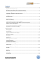
Instruction Manual Version 1.3 August 31, 2010 Instruction Manual Contents Introduction ........................................................................................................................................... 4 Sega 315-5246 Audio/Video chip ....................................................................................................... 4 PAL/NTSC Encoder 50/60Hz real-time software switchable............................................................... 5 MOS Technology 6581 or 8580 Sound Interface Device (SID) ............................................................ 5 128 Megabit (16Megabyte) addressable memory ............................................................................. 5 Configurable memory......................................................................................................................... 6 The Spartan FPGA............................................................................................................................... 6 JTAG Connector .................................................................................................................................. 6 PSG to SCC redirecting........................................................................................................................ 6 Joystick, Keyboard and OPLL to MSX remapping................................................................................ 6 Support for Sega SG-1000 / SC-3000 / MARK III / Master System games........................................... 7 Software switch for VDP addresses .................................................................................................... 7 13 sound-channels and SID filter controllable .................................................................................... 7 Gold plated slot-connector for durability ........................................................................................... 8 Using the PlaySoniq ................................................................................................................................ 8 Starting a game .................................................................................................................................. 8 Playing SID files .................................................................................................................................. 9 Using the 512MB Konami SCC+ Mapper .......................................................................................... 10 Adjusting the mapper ....................................................................................................................... 10 Dual display ...................................................................................................................................... 10 PSG over SCC .................................................................................................................................... 10 Switching between TV standards ..................................................................................................... 11 Testing the PlaySoniq ....................................................................................................................... 11 Programming the PlaySoniq ............................................................................................................. 11 Technical information for programmers .............................................................................................. 12 Things to know ................................................................................................................................. 12 Emulation of joystick and keyboard ................................................................................................. 12 VDP Wait .......................................................................................................................................... 14 Memory............................................................................................................................................ 14 Addressing ........................................................................................................................................ 17 Hold mapper .................................................................................................................................... 20 SCC Emulation .................................................................................................................................. 20 2 Instruction Manual Addressing ........................................................................................................................................ 22 Troubleshooting ................................................................................................................................... 23 Sound output ................................................................................................................................... 23 Video output .................................................................................................................................... 23 Distorted screen when running a Sega game ................................................................................... 23 Game hangs during play ................................................................................................................... 23 Game does not start at all ................................................................................................................ 23 Memory not displayed correctly during boot ................................................................................... 24 Memory mapper does not work ...................................................................................................... 24 Flashing capslock light or clicky sounds when powering up the PlaySoniq ...................................... 24 Does not work in slot expander ....................................................................................................... 24 Dual display not working .................................................................................................................. 24 Appendix A ........................................................................................................................................... 25 VGA-type connector ......................................................................................................................... 25 Appendix B ........................................................................................................................................... 26 Compatibility matrix ......................................................................................................................... 26 Appendix C ........................................................................................................................................... 28 Detailed information of overlay codes ............................................................................................. 28 3 Instruction Manual Introduction Thank you for buying our new product, the PlaySoniq multi-expander for MSX. We hope that you will have hours of fun with it. At least we do! The PlaySoniq is the result of over a year of hard work. FROM making the complex design of the expander to programming the VHDL code, and the work for finding and collecting the necessary electric components. The PlaySoniq is an advanced device and can be of great use for the casual MSX user but also for those of you who still invest time to develop great new products for MSX. We advise you to take some time to read this document to understand what the PlaySoniq can and can’t (yet) do. What is the PlaySoniq exactly? Let’s go over its specifications first. Sega 315-5246 Audio/Video chip The Sega Mark III and the first Sega Master System game consoles have a 315-5124 Audio/Video processor. The differences between this chip and the newer 315-5246 (that we use on the PlaySoniq) is that the old one has a hardware bug that caused improper PAL CVBS encoding. Also, the newer 315-5246 chip has distinct 224 and 240 line-modes which can be set and are used in some newer games. Also build-in is a programmable sound generator that is somewhat comparable with the PSG in your MSX. The PSG in the Sega processor is compatible with the Texas Instruments SN76489(A). This PSG is used in many home and game computers such as the ColecoVision. The video part of the Sega A/V processor is backwards compatible with MSX1 video modes, with a slightly different (harder) color palette. 4 Instruction Manual PAL/NTSC Encoder 50/60Hz real-time software switchable The Advanced Devices AD724 PAL / NTSC Encoder does what it says: it creates the color carrier and video signals for RGB and composite (CVBS) output. The PlaySoniq has its own PAL crystal onboard but as your MSX by default also gives the NTSC clock signal we have made it so that you can actually switch between NTSC and PAL encoding, and also choose between a 50hz or 60Hz refresh frequency. This eliminated building different versions of the PlaySoniq for us, and you can play your favorite Japanese games in 60Hz on your European displays (or the other way around) when your TV or monitor supports this. MOS Technology 6581 or 8580 Sound Interface Device (SID) Included in the PlaySoniq is a MOS Technology Sound Interface Device (SID). The SID was created in 1981 by engineer Robert Yannes and has been used in different Commodore models such as the Commodore 64 and 128 range of home computers. It has a few features that gives the SID its own unique sound and has a lot of users, even today. For example devices like the SIDstation or HardSID exist that are custom made synthesizers and need to be supplied with one or multiple real SID’s. Its main specifications as used on our expander: three separately programmable independent audio oscillators (8 octave range, approx. 16 4000 Hz) four different waveforms per audio oscillator (saw-tooth, triangle, pulse, noise) one multi-mode filter featuring low-pass, high-pass and band-pass outputs with 6 dB / octave (band-pass) or 12 dB / octave (low-pass / high-pass) roll-off. The different filter-modes are sometimes combined to produce additional timbres, for instance a notch-reject filter three attack / decay / sustain / release (ADSR) volume controls, one for each audio oscillator three ring modulators oscillator sync for each audio oscillator Three different versions of the SID exist, the 6581, the 6582 (not commonly used) and the 8580. Our expander supports the 6581 and the 8580. Due to shortage of SIDS, we use the 8580 or the 6581, depending on which are available during the manufacturing process. Please note that replacing one type with another type also needs some technical modifications on your expander because both types use a different voltage and filter. Connecting the SID to MSX has been a long term wish for some of us. But challenges had to be overcome. The SID needs a clock speed of around 1MHz, as opposed to the clock speed of MSX (standard about 3.57Mhz). Buffers had to be implemented so that writing to the SID from a MSX would not result in stuttering sound. Furthermore, PAL and NTSC versions of Commodore computers also have slightly different internal clock speeds, and we also needed to support those. The FPGA processor creates and can switch between those clock speeds. 128 Megabit (16Megabyte) addressable memory The MSX has four sub-slots for memory banks and each can address a maximum of 4 Megabytes. The PlaySoniq contains a memory chip and programmed logic to support the maximum of 16 Megabytes your MSX can handle. The memory mapping system that handles the addressing of the memory can 5 Instruction Manual be configured in a few different ways, or completely disabled. By default it is configured as three slots of 4MB and one slot for the Konami SCC+ mapper (more details about that below) Configurable memory As stated above, our memory mapping system can be configured in a few different ways. The memory system in the Sega game consoles is similar to that of MSX, but not exact. For our first Sega expander called Franky, all Sega programs had to be patched before they could run on MSX. For the PlaySoniq we made an extra memory mode that is compatible with Sega Master System consoles. Another reason to implement this flexible system is to be able to support a memory mode that emulates a Konami Snatcher / SD Snatcher Sound Cartridge mapper. Those cartridges featured buildin memory. Loader programs have been made in the past to run games in that memory. This way you could play your favorite games with SCC+ support from within that cartridge. Later Spanish engineer Manuel Pazos created a compatible cartridge with 512KB memory to load bigger programs. The PlaySoniq is also compatible with that memory configuration. Please note that the PlaySoniq does not contain a Flash ROM as the Mega Flash ROM SCC does. The Spartan FPGA To support the flexible memory mapper, the SID, the build-in support for SCC and SCC+ sound chips, the advanced logic to reroute the MSX keyboard, joysticks and MSX-MUSIC for Sega games (and a lot of other cool things too) we needed a Field Programmable Gate Array (FPGA). With an FPGA you can load hardware designs of existing chips or new things hardware developers create. An FPGA is for hardware as an EPROM is for software. We used a Xilinx Spartan II, model XC2S50. This specific revision has support for 5 volt input which the MSX supplies on the cartridge connector. The Spartan FPGA runs on 80MHz and has its own crystal to generate the necessary clock speed. Because the PlaySoniq is independent of the MSX clock all generated sounds are not affected by an MSX running at 7MHz. JTAG Connector A JTAG Connector is an industry standard to program the boot ROM of an FPGA. For example: the one chip MSX also has a JTAG connector so users can reprogram the included Altera FPGA. We are planning to release our source code in the near future so experienced users can adjust or enhance the functionality inside the FPGA. PSG to SCC redirecting A while ago we were inspired by functionality of the OpenMSX MSX emulator. It featured a script that could play PSG sound over SCC. Since our SCC implementation is done in FPGA we could also implement this cool feature. Best thing is that it works with every program that outputs PSG, even ROM binaries. Joystick, Keyboard and OPLL to MSX remapping While the first joystick port on a Sega Master System works the same as the second joystick port on MSX, the first Sega Joystick port does not. And, although not many games support two players, these could not be played on our first expander without severe modification of the original software. Also, there was no support for the MSX keyboard. This has now been solved. When a Sega game is loaded, 6 Instruction Manual it’s loaded in the memory mapper of the PlaySoniq (in Sega memory mode). Special code in the FPGA reads the keyboard and / or joysticks of the MSX and maps this back to the running game. The Japanese version of the Sega Master System also has a Yamaha YM2413(OPLL) sound chip buildin. This chip is also used in the MSX-MUSIC specification and FM-PAC. A total of 64 SMS games support OPLL. Since only the addressing is different we also manage to reroute the OPLL calls to the one in your MSX. We call this real-time code injection ‘overlaying’. This is important to remember, because our loader software will ask you for it later. You can choose to activate this before loading a game, or disable it. More info on how to tweak the overlay function can be found in our chapter ‘technical information for programmers’. Support for Sega SG-1000 / SC-3000 / MARK III / Master System games As you might now by now, our expander can run Sega Master System games. Before Sega made the Master system, it made the Mark III (which is compatible) and before that, the Sega SG-1000 and SC3000. The latter two are machines with a TMS9918 (MSX1) video chip but share the same memory layout as the Sega Master System (and have a compatible audio chip). And because the Sega Master System Video part is backwards compatible, so is our expander. Please don’t forget to rename the extension of your .SG files to .SMS . This way our loader software will accept those files also. Software switch for VDP addresses By default the Sega VDP can be accessed the same way as our Franky expander. This is to ensure backwards compatibility with software that supports Franky, such as Kralizec excellent game ‘The Goonies 'R' Good Enough’. The PlaySoniq can also be set to address the VDP in a MSX1 mirror mode. This works on MSX1 and MSX TurboR (The MSX TurboR can be tricked to load a MSX1 BIOS), and only with programs and games for MSX1. When this mode is activated you can see your MSX1 program on two displays at once, if you connected the PlaySoniq output to another display. The ColecoVision has the same video chip as MSX1 home computers and the same audio processor as the audio part of the Sega A/V processor. We have made it possible for developers to switch the addresses of the VDP part to those of the ColecoVision for easier porting of existing software. The Memotech MTX range of home computers is lesser known, but those features a Z80 microprocessor, a TMS9929 video chip (same as the MSX1 video chip except different color encoding output) and also the same audio processor as used in the Sega and ColecoVision. We hope someone tries to get the Memotech software running on the PlaySoniq. For starters, you can set the VDP to Memotech mode for the same VDP addresses as in the real hardware. 13 sound-channels and SID filter controllable The SID audio processor also supports audio input. While Commodore never used this feature of the SID processor, we were glad to have this. We used it to connect the five channels of the SCC+ and the four channels (three sound + one white noise) of the Sega A/V processor. This gives you, together with the four audio channels of the SID (three sound + one white noise), thirteen sound channels. 7 Instruction Manual Connecting the SCC+ and the Sega sound to the SID input saved us an extra output connector on the PlaySoniq. And it gives developers the possibility to use the build-in filters of the SID to add effects on all sound channels that pass through the SID, or from the SID itself. Maybe we should say 14 soundchannels to choose from because developers can switch between SCC functionality or an 8-bit D/A converter to play samples. Gold plated slot-connector for durability Oxygen together with time can do strange things to most metals so we decided to invest a little more to gold plate the cartridge connector of the PlaySoniq. This way we ensure that you can enjoy our expander as long as possible. The PCB of the PlaySoniq also has an extra protective coating. Using the PlaySoniq Since the PlaySoniq is a very complex device, please make sure you MSX is turned off before inserting or removing the PlaySoniq. The cable to connect the output of the PlaySoniq to your TV or monitor can be steady mounted to the PlaySoniq with a screwdriver. Please make sure that there is no tension on the cable. Too much tension can cause damage to the output connector or the cable. Please note that although we used a VGA type connector for durability, this connector is not compatible with the VGA standard used on more modern pc’s. Connecting the PlaySoniq to a VGA monitor can cause irreversible damage to the PlaySoniq and / or your VGA monitor. When you have inserted the PlaySoniq and powered on your MSX, you might experience a slight delay in booting. This is because the PlaySoniq needs some time to boot the FPGA and until this process is finished the booting process of the MSX will be paused. The PlaySoniq will detect if it’s run on a PAL or NTSC MSX and will adjust the color carrier signal accordingly. If you use the PlaySoniq in a MSX1, all screen output can be redirected to the Sega VDP and thus to the output connector. This can be useful in situations where you have only one monitor. It also saves you from switching between displays. Starting a game For the PlaySoniq we have made a loader tool that can load Sega Master System and MSX ROM binaries into the PlaySoniq. You can download the file PS-files.zip from our website. Unpack the files in a directory containing your games and start the loader by typing “sega.bas’ from basic. Or type ‘basic sega.bas’ in the correct directory from MSX-DOS. The loader will show all ROM and SMS files in the directory (or as much as your screen can display) and will then ask a few questions: Enter name of game: Please type the name of the ROM or SMS (without the extension) that you want to load here. Play at 60Hz?:If you type in y, the game will start in 60Hz, if you type in n, the game will be started in 50Hz. 8 Instruction Manual Use FM-PAC?: If you type in y, the overlay to reroute Sega games with support for OPLL will be started. If you type in n, this function will be disabled. Combine SCC sound for PSG games?: If you type in y, all MSX PSG sound will also be rerouted to the SCC implementation on the PlaySoniq. Please note that this option only works for the PSG sound chip of the MSX, not the PSG of the Sega A/V processor. You will only see this option when loading MSX ROMs. Enable SCC+ mode?: You can active this mode for games that support the Snatcher or SDSnatcher cartridge. This question will only be asked when loading MSX ROMs. Both VDP’s?:With this option you can mirror the MSX screen on the Sega VDP. This option only works for MSX1 games. If you experience problems after loading your game, please try to load it with another option for the display frequency. Or try without activating the FM-PAC option. Some games are not programmed for 60Hz. Activating the FM-PAC option will start the FPGA overlay mode and this may conflict with a few time critical games such as Aleste (Powerstrike) or Afterburner. Playing SID files The high voltage SID collection is a website that contains over 37.000 SIDS songs (and growing). SID songs on this website contain SID files in the PSID and RSID format. Finnish MSX user NYYRIKKI made a replayer for MSX-DOS called sidplay that also supports the SID on our expander. The current version of sidplay only supports the PSID file format. Some PSID files make use of a non-standard timer and this is not yet supported in the replayer. Still, thousands and thousands of SID songs can already be enjoyed. The latest version of sidplay.com can be downloaded from the download database at www.msx.org. Please note that you need the map.com utility if you want to run this tool under MSX-DOS2. 9 Instruction Manual Usage is sidplay <name of song>. Some SID files contain more than one song. This will be displayed after you start the song for the first time. Afterwards you can type sidplay <number of song> to listen to the other songs contained in the same file. Inside our software package is a MSX-DOS utility called sidtype.com. This utility will tell you if you have a 6581 or 8580 SID in your PlaySoniq. Some SID files are specifically made for either one and will sound different on the other one. Sidplay will play all SID files no matter which SID is installed. In the future Sidplay will read which SID is installed and tell you if a song was made for your SID, or not. More info on how to use the SID in your own programs can be found in in our chapter ‘technical information for programmers’ Using the 512MB Konami SCC+ Mapper The default configuration of the PlaySoniq also has a 512MB SCC+ Mapper in sub-slot 4. This mapper can be used with tools like Romload made by Albert Beevendorp (BiFi) of TNI to load Konami megaroms. His tool can be downloaded from http://www.tni.nl/products/romload.html. Romload can also convert ROMs in ASCII/8 or ASCII/16 format on the fly. Adjusting the mapper In our software package are two MSX-DOS utilities for the build-in mapper. Mapoff.com will disable the mapper. This is useful for programs that only work in the internal memory of your MSX. On MSX and MSX2 this utility will soft reset your MSX, on TurboR machines you need to press the reset switch. Powering off your MSX for a few seconds will clear this setting and restore the default mapper settings. Please note that in most cases you will not need to use this utility. Map2mb.com will set the mapper in 2MB per sub-slot, instead of the default 4MB. You can use this utility for programs that are not compatible with the 4MB default configuration. Soft reset your MSX when your MSX is not automatically rebooted. Power your MSX off for a few seconds to restore the default mapper setting. Dual display With our utility bothvdp.com you can put the video part of the Sega A/V chip in the MSX1 compatible mode. After running, all screen output will also be send to the video output of the PlaySoniq. Please note that running this utility on MSX2 or higher will result in garbage on the PlaySoniq video output. PSG over SCC Ever dreamed of playing Usas or Zanac with SCC sound? With our utility SCCPSG.com now you can. Typing SCCPSG in MSX-DOS will also route all PSG output to the SCC implementation of the PlaySoniq. Although music and sound effects sounds great on the SCC, it lacks a lot of parameters the PSG has. So results may vary depending on title. This utility is not needed when you use the loader program, as our loader will ask you if this should be enabled. 10 Instruction Manual Switching between TV standards With the utility NTSC.COM you can set the PlaySoniq to output a NTSC signal. With PAL.COM you can set the PlaySoniq in the European PAL standard. By default the PlaySoniq will try to detect the standard color carrier so in most cases you will not need to switch this manually. Testing the PlaySoniq We have made a small basic program to test the main functions of the PlaySoniq. It is called SONQTST.BAS. After running, you can change between the color carrier signal, the screen frequencies, and play some tones over the SID, the SCC and the Sega PSG. With the file SMSPSG.BAS you can type in a frequency number and hear the tone over the PSG of the MSX and the Sega PSG. Programming the PlaySoniq Detailed information about how to program for the memory or the SID on the PlaySoniq or tweak specific settings such as the keyboard overlay can be found in in our chapter ‘technical information for programmers’ Information about programming the Sega video and audio processor has been covered in detail in the user manual of our first Sega expander, Franky. This document can also be found in the document section of our website. 11 Instruction Manual Technical information for programmers Things to know At startup the PlaySoniq expander produces a WAIT signal of 200ms. This time is required by the FPGA to load its configuration. Most MSX systems start searching for memory before the FPGA has finished the start-up sequence. This is the only case where a WAIT is generated. This delay at startup can sometimes result in a flashing CAPS led and a click sound from the motor relay. The led and relay are always enabled at startup, but for much shorter time which is usually not noticeable. Emulation of joystick and keyboard Our expander is not able to access the joystick port (PSG) and keyboard port (PPI) of the MSX directly. As a game is stored in the memory of the expander it has the possibility to modify the data of the game on the fly. Special code will be executed to let the MSX read the joystick and keyboard, the MSX will void this data but in the meantime our expander reads the data coming from joystick and keyboard. This data is stored in our expander and shows it at port &HDC and &HDD as soon the Sega game reads these ports. When this special code is finished, an relative jump to the first instruction of this code will restore the address so the normal game data can continue. On a read of I/O port &HDC, the port where Sega games read out the joystick information, an alternative code is shown to the MSX instead of the game data. A disadvantage of this is the extra time needed for this code to run. A few games will crash or show glitches in the screen when they use very time critical timings. To help tackle this we implemented 11 different compromises, all using different pieces of code which read keyboard and joystick. Some options are alternating these small pieces of code to reduce the length of one reading. This results in a slower response time because the joystick will be read out only one of the 2 or 3 readings: 0 1 2 3 4 5 6 7 8 9 10 11 No code to readout keyboard and joystick Both keyboard and joysticks are read Keyboard and one joystick will be read out, select joystick before starting a game Both joysticks will be read out, no keyboard Both keyboard and joysticks are read alternated, 1 out of 3 readings Only keyboard Only keyboard and interleaved, very short code for very time critical games Keyboard and one joystick interleaved, select joystick before starting a game Keyboard, only button A and one joystick. Select joystick before starting game. Keyboard, only button A. One joystick, select joystick before starting a game. Keyboard, only button A and one joystick alternated. 12 Instruction Manual Switching between joysticks takes a lot of time as this is selected by a register in the PSG which has to be enabled first. The options which offer ‘one joystick’ require a pre selection before executing a game. The joystick port which should be active is selected by bit 6 of register 14 of the PSG, after this, also register 14 should be enabled. This is not done while reading the joystick to minimize code length and execution time. In case of one joystick, pre-selection can be done in machine code or basic: LD OUT LD OUT LD OUT Joystick 1 A,15 (&HA0),A A,143 (&HA1),A A,14 (&HA0),A LD OUT LD OUT LD OUT Joystick 2 A,15 (&HA0),A A,207 (&HA1),A A,14 (&HA0),A Joystick 1: OUT &HA0,15:OUT &HA1,143:OUT &HA0,14 Joystick 2: OUT &HA0,15:OUT &HA1,143:OUT &HA0,14 After the last instruction the real code will be executed. These instructions achieve that the joystick data and keyboard data is shown at the databus and stored in the cart. When a game reads I/O address &HDC or &HDD to read the Sega gamepad, the stored data will be shown to the game. See appendix C for details about the overlay codes. 13 Instruction Manual VDP Wait No wait states are added for data transfer to memory or SID. The data send to the SID is buffered in the FPGA and then send to the SID at the time the SID can accept data. For the VDP this is not possible as most software is synchronized with the VDP. Not implemented yet: using the WAIT line to the MSX to prevent too fast access to the VDP only. Some delay will be required when a game will be played in R800 mode. Memory The total of 16megabytes RAM can be mapped via three different types: Expanding the slot used for PlaySoniq, 4Mb each sub-slot Expanding the slot used for PlaySoniq, 4Mb in sub-slot 0,1&2 + SCC in sub-slot 3 (default) Expanding the slot used for PlaySoniq, 2Mb each sub-slot Expanding the slot used for PlaySoniq, 2Mb in sub-slot 0,1&2 + SCC in sub-slot 3 Extending I/O address &HFC-&HFF with &HF8-&HFB Extending I/O address &HFC-&HFF with &HF8-&HFB + SCC when &HF8 to &HFB set to 3 Map the memory by memory address &HFFFC-&HFFFF (Sega) Extending I/O address &HFC to &HFF: The 16k ram in page 3 (&HC000 - &HFFFF) is selected by the 8 bits of I/O address &HFF, this gives a total of 16k*256=4096kbytes of RAM. To access the 16384kbytes two additional bits are needed, these are programmed at address &HFB for page 3. AA AAAAAAAA 22 22111111 32 10987654 Page Page Page Page 3 2 1 0 FB FA F9 F8 FF FE FD FC (Memory (Memory (Memory (Memory address address address address &HC000-&HFFFF) &H8000-&HBFFF) &H4000-&H7FFF) &H0000-&H3FFF) Expanding the slot will result in a slot expander with four times 4mbytes or four times 2mbytes, this is according to the MSX standard. Expanding the slot will not work when the PlaySoniq is inserted into a slot expander which does not mask the sub-slot register. To achieve the full 16mbytes, set bits 1 and 0 of register 31 to 0 and disable the SCC+ emulation. 14 Instruction Manual Switching the size of the mapper and mapper mode can be done in real-time, if for example sub-slot 2 is used for the current program and the mode is switched from slot expansion to extending mapper I/O ports, the contents of the extended I/O ports will represent the sub-slot instead. Programs which have some memory management will require a reboot as there is suddenly no slot expander anymore, therefore we implemented the possibility to maintain the mapper mode settings after a reset. Mapping with address &HFFFC to &HFFFF is based on the Sega Master System mapper. Note that as soon this mapper is selected the upper 2mbytes will show up at the first page, the Sega RAM will be the first 8k of the memory, the second 8k is not accessed and the Sega SRAM will be the second 16k. This is done to make switching of the mapper mode possible when the PlaySoniq memory is used by the MSX itself. If, as by default, I/O address &HFF is set to 0, the first 8k of the first sub-slot will be used in address space &HC000-&HDFFF. When switching to Sega mapper mode, this same part of memory is still at &HC000-&HDFFF. This is not the case when the Sega mapping is selected. Then there is a difference in the mapping system and address space &HC000 to &HFFFF will be fixed. If the Sega mapping is enabled, the first half of the red 16k block will be fixed at address &HC000 to &HDFFF and mirrored at &HE000 to &HFFFF (see next page for diagram). The yellow part will be moved to the first pages to avoid conflicts with the operating system when loading a game. For loading a game, load the first 16k block into mapper page 128. Some games also use RAM pages, if a RAM page is selected by a game, the blue pages which are normally mapped at page 126 and 127 will be used. Data from this page can then be saved after a reboot. All other memory visible at sub-slots or with I/O &HF8 to &HFB will not be used when the Sega mapper is active. The grey blocks are also not used then. The pages mentioned in the next overview are the numbers written to I/O address &HFC to &HFF. 15 Instruction Manual Map Subslot (default): IO FCFF: 0 1 2 3 … 124 125 126 127 128 129 … 254 255 IO F8FB: 0 0 0 0 0 0 0 0 0 0 0 0 1 1 1 1 2 2 2 2 3 3 3 3 Subslot 0 16k 16k 16k 16k Subslot 1 16k 16k 16k 16k Subslot 2 16k 16k 16k 16k Subslot 3 16k 16k 16k 16k 16k 16k 16k 16k 16k 16k 16k 16k 16k 16k 16k 16k 16k 16k 16k 16k 16k 16k 16k 16k 16k 16k 16k 16k 16k 16k 16k 16k 16k 16k 16k 16k Map F8: IO FCFF: 0 1 2 3 … 124 125 126 127 128 129 … 254 255 0 … 127 128 … 255 0 … 127 128 … 255 0 … 127 128 … 255 Switching from subslot to Sega mapper system Subslot Subslot Subslot 0 1 2 Subslot 3 0 16k 16k 16k 16k 1 16k 16k 16k 16k 2 16k 16k 16k 16k 3 16k 16k 16k 16k … 124 16k 16k 16k 16k 125 16k 16k 16k 16k 126 16k 16k 16k 16k 127 16k 16k 16k 16k 128 16k 16k 16k 16k 129 16k 16k 16k 16k … 254 16k 16k 16k 16k 255 16k 16k 16k 16k (Sub)slot 16k 16k 16k 16k IO F8FB: 0 0 0 0 16k 16k 16k 16k 16k 16k 0 0 0 0 0 0 16k 16k 16k 0 0 1 16k 16k 1 1 16k 16k 1 2 16k 16k 2 2 16k 16k 2 3 16k 16k 3 3 16k 3 Map F8: IO FCFF: 0 1 2 3 … 124 125 126 127 128 129 … 254 255 0 … 127 128 … 255 0 … 127 128 … 255 0 … 127 128 … 255 (Sub)slot 16k 16k 16k 16k 16k 16k 16k 16k 16k 16k 0 1 2 3 … 126 127 Map Sega: Addr FFFCFFFF: 16k 16k 16k 16k 16k 16k 16k 16k 16k 16k 16k 16k 16k 16k 16k 16k 16k 16k 16k 16k 16 Instruction Manual Addressing To reduce the amount of I/O space, some settings are concatenated with the registers of the SID. The lowest 5 bits of I/O address &H2A determine the register number, I/O address &H2B contains the corresponding data. Registers &H00 to &H1C are directly the SID registers according to the SID datasheet, registers &H1D to &H1F are for PlaySoniq settings. The data can be read back at &H2B at any time, registers &H19 to &H1C are read back from the SID. The SID normally is a write only device but in the PlaySoniq all other SID registers are mirrored internally by the FPGA. Address &H2A: Register number &H2B: Data &H2C: Write: 8 bit audio DAC Read: bit 0 indicates type of SID: 0=6581 1=8580 &H2D: Used for joypad data or temporary data in overlay function 17 Instruction Manual Registers accessible via I/O address &H2A: &H00 F7 F6 F5 F4 F3 F2 F1 F0 Voice 1 Freq Lo &H01 F15 F14 F13 F12 F11 F10 F9 F8 Voice 1 Freq Hi &H02 PW7 PW6 PW5 PW4 PW3 PW2 PW1 PW0 Voice 1 PWLO &H03 - -_ - - PW11 PW10 PW9 PW8 Voice 1 PWHI &H04 NOISE | |_| /|/| /\/\ TEST Ring SYNC GATE Voice 1 Control Reg &H05 ATK3 ATK2 ATK1 ATK0 DCY3 DCY2 DCY1 DCYO Voice 1 Attack/Decay &H06 STN3 STN2 STN1 STN0 RIS3 RIS2 RIS1 RIS0 Voice 1 Sustain/Release &H07 F7 F6 F5 F4 F3 F2 F1 F0 Voice 2 Freq Lo &H08 F15 F14 F13 F12 F11 F10 F9 F8 Voice 2 Freq Hi &H09 PW7 PW6 PW5 PW4 PW3 PW2 PW1 PW0 Voice 2 PWLO &H0A - -_ - - PW11 PW10 PW9 PW8 Voice 2 PWHI &H0B NOISE | |_| /|/| /\/\ TEST Ring SYNC GATE Voice 2 Control Reg &H0C ATK3 ATK2 ATK1 ATK0 DCY3 DCY2 DCY1 DCYO Voice 2 Attack/Decay &H0D STN3 STN2 STN1 STN0 RIS3 RIS2 RIS1 RIS0 Voice 2 Sustain/Release &H0E F7 F6 F5 F4 F3 F2 F1 F0 Voice 3 Freq Lo &H0F F15 F14 F13 F12 F11 F10 F9 F8 Voice 3 Freq Hi &H10 PW7 PW6 PW5 PW4 PW3 PW2 PW1 PW0 Voice 3 PWLO &H11 - -_ - - PW11 PW10 PW9 PW8 Voice 3 PWHI &H12 NOISE | |_| /|/| /\/\ TEST Ring SYNC GATE Voice 3 Control Reg &H13 ATK3 ATK2 ATK1 ATK0 DCY3 DCY2 DCY1 DCYO Voice 3 Attack/Decay &H14 STN3 STN2 STN1 STN0 RIS3 RIS2 RIS1 RIS0 Voice 3 Sustain/Release &H15 - - - - - FC2 FC1 FC0 Filter FC Lo &H16 FC10 FC9 FC8 FC7 FC6 FC5 FC4 FC3 Filter FC Hi &H17 RES3 RES2 RES1 RES0 FltEx Filt3 Filt2 Filt1 Filter Res/Filt &H18 3Off HP BP LP Vol3 Vol2 Vol1 Vol0 Filter Mode/Vol &H19 PX7 PX6 PX5 PX4 PX3 PX2 PX1 PX0 Misc Pot X Read-only &H1A PY7 PY6 PY5 PY4 PY3 PY2 PY1 PY0 Misc Pot Y Read-only &H1B O7 O6 O5 O4 O3 O2 O1 O0 Misc Osc3/Random Read-only &H1C E7 E6 E5 E4 E3 E2 E1 E0 Misc Enveloppe3 Read-only &H1D VA7 VA6 VA5 VA4 VA3 VA2 VA1 Read Cart VDP address &H1E AA7 AA6 AA5 AA4 AA3 AA2 AA1 Read Cart Audio address &H1F AntoN CNTSC VNTSC SNTSC SCC - Map1 Map0 Cart Video/Mapper &H20 PADO Overlay type &H21 PADK FMDET FMOUT | | Ov RGB S+P INTM TMS TCK TDI/O JTAG Misc Overlay Misc .... &H3F Firmware update For registers &H00 to &H1C please refer to the SID datasheet. 18 Instruction Manual Register &H1D: This sets the base address of the VDP. When the read bit is set, reading from the VDP is inhibited. Register &H1E: Same as &H1D for the PSG. Registers &H1D and &H1E can be useful for running software of other consoles, for example: ColecoVision: Set &H1D to &HBE Set &H1E to &HFF Note: PSG conflicts with memory mapper, set read inhibit Sega: Set &H1D to &HBE Set &H1E to &H7E MTX512: Set &H1D to &H00 Register &H1F: 7 AutoN: 6 CNTSCC: When this bit is set, the video standard is according to bits 4-6. When reset, the card selects the same standard as the MSX2 VDP. The composite video signal will have the NTSC system when this bit is set, otherwise it will be PAL standard; NTSC: Chroma = 3,579545MHz PAL: Chroma = 4,433619MHz, phase alternating 5 VNTSC: With this bit the number of horizontal video lines is selected, set for NTSC. NTSC: 567 lines (60Hz refresh rate) PAL:625 lines (50Hz refresh rate) 4 SNTSC: When this bit is set, the clock of the SID will be the same as used in the C64 NTSC mode. NTSC: SID clock is 1,023MHz PAL: SID clock is 0,985MHz 3 Hld mapper This bit keeps the settings of the mapper after a hard reset. 2 SCC: SCC emulation in sub-slot 3, in this case the RAM in this sub-slot cannot be used. 1 - 0 Map 00 = 16Mb, the slot is expanded, 4Mb each sub-slot 01 = 16Mb, slot not expanded, extra mapping bits on &HF8 to &HFB used 10 = 8Mb, the slot is expanded, 2Mb each sub-slot (default) 11 = 1Mb following the Sega mapper system 19 Instruction Manual Register &H20: 7 PADO: This bit sets enables the emulation of pad registers &HDC and &HDD 6 PADK: This bit is used for Turbo-R as reading from &HDC and &HDD is blocked by Turbo-R hardware. Disadvantage is the accumulator is not stored during overlay which might cause problems in games. 5 FMDET Enables FM detection as Sega standard with I/O address &HF2 4 FMOUT Generates an overlay for copying FM data to the MSX FM-Pac 3 – 0 Overlay Defines the type of the overlay as described before Register &H21: 2 RGB: This bit sets the RGB Status signal, the TV or monitor will switch to RGB instead of composite. 1 S+P Let’s SCC join the PSG sound 0 INTM Masks the interrupt from the Sega VDP Register &H22-&H3E are completely unused at the moment of 1st release. Register &H3F is for possible firmware update in future, these are the JTAG bits used for programming the bootrom of the FPGA. Be aware, when the firmware is messed up, it is not able to boot or reprogram without the JTAG connections on the PCB! This register should be left alone… Hold mapper In some cases it can be useful to disable the internal memory, the size of the internal memory or the slot expansion of the PlaySoniq. After changing these settings the MSX should reset for proper operation of DOS and other memory managers, this bit makes sure the mapper settings will remain until a power cycle is performed. SCC Emulation When SCC emulation is enabled by setting bit 2 of register &H1F, normally sub slot 3 will be used. Page 0 and 3 will be empty, page 1 and 2 are mapped like the Konami megarom SD-Snatcher (SCC+). Together with SCC mapper the normal mega ROM mapper system is used, this means switching between pages can be done at address &H5000, &H7000, &H9000 and &HB000 for blocks 0,1,2 and 3, but also &H4000, &H6000, &H8000 and &HC000 are valid. Some uploaded games require a reboot of the MSX, e.g. Solid Snake appears not to accept RAM in the same primary slot. Therefore the slot expander will be disabled in the loader tool provided with PlaySoniq. The card will write 00 to address &H4000 after a hard-reset or power cycle to prevent the MSX of starting a game again. 20 Instruction Manual Examples and tips for programmers: There are program’s which require an SCC in the primary slot, if the SCC is enabled in a primary slot the memory will disappear… When using an MSX Turbo-R this is no issue because the internal memory will be the primary memory anyway, for other MSX machines the easiest solution is to: Disable the slot expander and enable the SCC (OUT &H2A,31:OUT &H2B,5) Select the highest part of the memory (OUT &HF8,3:OUT &HF9,3:OUT &HFA,3:OUT &HFB,3) Perform a soft or hardware reset to let it use the internal memory There are also megaroms like Solid Snake and Pennant Race 2 which don’t work in an expanded slot, in this case SCROM can be used to upload those games without –S option, and add the same trick as above: OUT &H2A,31:OUT &H2B,5:OUT &HF9,3:OUT &HFA,3:DEF USR=0:A=USR(0) Some games extracted from Konami’s Game Collection which should work with SCC+, don’t initialize the SCC properly. To start for example Knightmare with SCC+, use SCROM without –S option, go to basic and enter: OUT &H2A,31:OUT &H2B,5:OUT &HF9,3:OUT &HFA,3:POKE &HBFFF,32:DEF USR=0:A=USR(0) Solid Snake: Does not work in the same primary slot as the RAM slot, loaded as every other megarom OUT &H2A,31:OUT &H2B,5:OUT &HF9,3:OUT &HFA,3:DEF USR=0:A=USR(0) After a soft reboot the MSX will use its internal memory. SCC+: Some converted games like Twinbee of Konami Games collection seems not to enable SCC+ mode, in this case it can be done manually: OUT &H2A,31:OUT &H2B,5:OUT &HF9,3:OUT &HFA,3:POKE &HBFFF,32:DEF USR=0:A=USR(0) What to do for SCC sound in primary slot? MSX2: OUT &H2A,31:OUT &H2B,5:OUT &HFA,3 *MSX2 uses RAM in the same slot, so reboot required *Turbo-R uses its internal RAM, changing SCC slot settings not harmful. Konami Games collection on Turbo-R: Memory and SCC+ in the same primary slot gives problems on the Turbo-R, therefore enter: OUT &H2A,31:OUT &H2B,13:OUT &HF8,3:OUT &HF9,3:OUT &HFA,3:OUT &HFB,3 to disable the memory and perform a hard or soft reset. 21 Instruction Manual Addressing To reduce the amount of I/O space, some settings are concatenated with the registers of the SID. The lowest 5 bits of I/O address &H2A determine the register number, I/O address &H2B contains the corresponding data. Registers &H00 to &H1C are directly the SID registers according to the SID datasheet, registers &H1D to &H1F are for PlaySoniq settings. The data can be read back at &H2B at any time, registers &H19 to &H1C are read back from the SID. The SID normally is a write only device but in the PlaySoniq all other SID registers are mirrored internally by the FPGA. Address &H2A: Register number &H2B: Data &H2C: Write: 8 bit audio DAC Read: bit 0 indicates type of SID: 0=6581 1=8580 &H2D: Used for joypad data or temporary data in overlay function 22 Instruction Manual Troubleshooting In this chapter we will address common issues when using the PlaySoniq and what you can do to avoid or solve them. Sound output All sound output that the PlaySoniq creates will also be feed to the MSX and on the Audio out connector of the PlaySoniq. Please bear in mind that sound from the MSX such as MSX-MUSIC or PSG is not send to the PlaySoniq. If you start a game and route the OPLL music to the MSX, you need to connect the audio output from the MSX to a monitor or stereo also to enjoy those sounds. A common problem with some MSX machines is that sounds that are send to the MSX over the cartridge connector are lower in volume than the internal sounds of the MSX. For example, if you run a game with SCC support you might hear only drums and the SCC vaguely in the background. To solve this you can either mix the audio output from the PlaySoniq connector with the Audio output from your MSX or open the PlaySoniq cartridge enclosure. Inside we have mounted a volume adjuster that you can adjust until sound is mixed to your liking. It’s also possible to use this volume control to disable any sound send to the MSX. Video output If you see black and white picture instead of a colorful game though the video output of the PlaySoniq you either have to use our NTSC.COM or PAL.COM MSX-DOS commands to force the PlaySoniq to display the correct output for your TV system. Try the SONQTEST.BAS program to check if your TV accepts any RGB or composite signal in PAL or NTSC format. Distorted screen when running a Sega game If you experience a messed up screen with wrongly displayed blocks try loading the game in 50Hz mode without any overlays active. Overlaying eats up some CPU time and this can result in messed up screens with time critical games. Refer to the programmer instruction manual to tweak the overlay settings. Also: a lot of bad ROM dumps exist. Some ROMs have customized header or extra header information because of the backup unit used. Try to use another source. Game hangs during play Luckily we only experienced this once during testing, but if you experience lock-ups during playing try loading the game in 50Hz mode without any overlays active. Overlaying eat up some CPU time and this can result in lock-ups. A lot of bad ROM dumps exist. Some ROMs have customized header or extra header information because of the backup unit used in the past. Try to use another source. Game does not start at all If you experience lock-ups during play try loading the game in 50Hz mode without any overlays active. Overlaying will eat up some CPU time and this can result in lock-ups. A lot of bad ROM dumps exist. Some ROMs have customized header or extra header information because of the backup unit used in the past. Try to use another source. 23 Instruction Manual Memory not displayed correctly during boot Please note that a lot of MSX computers don’t count external memory when you turn on your MSX. If you can run a Sega game (which is always loaded in the memory of the PlaySoniq) the memory mapper works. Memory mapper does not work Some MSX computers have been built with memory or other intern software in slots that normally weren’t used for that or not according to the MSX standard. Please try to disable any non-standard intern programs during boot. Also, reference our overview of all tested computers in the compatibility matrix located in appendix B. Check if your MSX works with other normal memory mappers of 512KB and higher. Flashing capslock light or clicky sounds when powering up the PlaySoniq Most MSX models test the drive and turn on the caps lock for a brief second during booting. Normally this goes fast so you don’t notice this. The PlaySoniq takes another extra half second and during this time you might experience this. Nothing to worry about. Does not work in slot expander PlaySoniq is not designed to use in a slot expander for several reasons: The MSX slot expander will conflict with our Sega memory emulation. Its internal user memory and mapper system requires expanding the primary slot The power consumption of the PlaySoniq equals the power needed for a slot expander Because of the design of most slot expanders the MSX won’t start up when the PlaySoniq is inserted into the expander Since the PlaySoniq has a build-in slot expander to address all the available memory, putting the PlaySoniq in an external slot expander will give unpredictable results to the MSX If for some reason the PlaySoniq must still run in an expander, switch off the sub-slots of the external expander at power-on. Dual display not working If you want to turn on the dual display feature of the PlaySoniq, make sure you inserted the PlaySoniq in an MSX1 (or you have tricked your TurboR in MSX1 mode, see our Franky manual for details). Else you will only see garbage on screen. Also, please note that MSX1 games that use VDP features outside the MSX1 BIOS commands and use direct VDP features not present in the Sega A/V processor may not display correctly, or not display at all. 24 Instruction Manual Appendix A VGA-type connector The connector used for the video and sound output of the PlaySoniq is a 15 pin standard VGA-type connector. The pin layout (seen as looking towards the connector) is as follows: Pin 1 Red Pin 2 Green Pin 3 Blue Pin 4 Not connected Pin 5 Ground Pin 6 Red ground Pin 7 Green ground Pin 8 Blue ground Pin 9 Not connected Pin 10 Ground Pin 11 5 Volt Pin 12 Not connected Pin 13 CVBS (Composite) output Pin 14 Audio Out Pin 15 Audio In Please note that although we used a VGA connector for durability, you cannot use this connector to connect the PlaySoniq card to a VGA monitor. Also, make sure that you have turned the volume on the PlaySoniq PCB off (with the volume control on the PCB) when you want to feed the MSX audio out signal into the audio input of the PlaySoniq (Pin 15). 25 Instruction Manual Appendix B Compatibility matrix These are the systems used for testing the PlaySoniq, tested was the memory, I/O and Sega support: Brand Type Version Test Result Canon Goldstar V-20 FC-200 MSX1 MSX1 Ok Memory and I/O okay, no 2nd slot to test games* Gradiente Expert DD+ MSX1 Does not start, Gradiente apparently does not support known slot expanders Gradiente JVC Mitsubishi Mitsubishi Mitsubishi Panasonic Panasonic Expert HC-7GB ML-FX1 ML-F80 ML-G10 CF2700 FS-A1F MSX1 MSX1 MSX1 MSX1 MSX2 MSX1 MSX2 Ok but with slot expander disabled Ok Ok Ok Ok Ok Conflicts with Panasonic firmware Philips VG8010 MSX1 Memory ok, could not test games due to broken keyboard Philips Philips Philips Philips Philips Philips Pioneer Sanyo VG8020/00 VG8020/40 NMS8220 NMS8235 NMS8245 NMS8255 PX-7 MPC-100 MSX1 MSX1 MSX2 MSX2 MSX2 MSX2 MSX1 MSX1 Ok Ok Ok Ok Ok Ok Ok Memory and I/O okay, no 2nd slot to test games* Sanyo Sanyo Wavy Sharp Hotbit Sony PHC-28S 70FD2 HB8000 HP-55P MSX1 MSX2+ MSX1 MSX1 Ok Ok Ok Games not playable because of keyboard Sony HP-75D MSX1 Games not playable because of keyboard Sony HB-201P MSX1 Memory and I/O okay, DOS does not work 26 Instruction Manual Sony HB-F5 MSX2 Sony Sony Sony Sony Sony Sony SVI HB-T7 HB-F9P HB-F500P HB-F501P HB-F1XDJ HB-F1XD 728 MSX2 MSX2 MSX2 MSX1 MSX2+ MSX2 MSX1 SVI 738 MSX1 I/O okay, no 2nd slot to test games*. BIOS chooses internal ram Toshiba HX-10 MSX1 Memory and I/O okay, no 2nd slot to test games* Turbo-R Yamaha GT CX5MII/12 8s YIS503F YC64 MSXTR MSX1 Ok Ok Yamaha Yashica Memory and I/O okay, conflict with firmware Ok Ok Ok Ok Ok Ok Memory and I/O okay, no 2nd slot to test games* MSX1 MSX1 Ok Memory and I/O okay, no 2nd slot to test games *Some models have a expansion port that can be converted to a real cartridge slot. We didn’t have this converter so we could not test the PlaySoniq together with a CF or SD-Card interface containing our software. Sony HB-55/ HB-75 MSX1 systems have a data buffer inside which masks internal data from the outside world. Therefore our expander cart is unable to read the MSX keyboard and joystick while playing Sega games. 27 Instruction Manual Appendix C Detailed information of overlay codes Keyboard 0 1 2 3 4 5 6 7 8 9 10 11 Simplified One Both Scan Extra Executed Keyboard Joystick Joysticks Interval cycles codes: * 1 1 2 3 1 2 3 1 1 1 2 222 103 99 103 92 63 63 56 45 45 45 1 2 3,4 2,3,4 5 6,7 6,7,8 9 10 11 10,11 * * * * * * * * * * * * * * * * 28