1
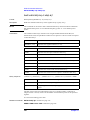
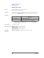
Agilent E4991A RF Impedance/Material Analyzer
Programming Manual
Sixth Edition
Agilent Part No. E4991-90062
September 2012
Notices
The information contained in this document is subject to change without notice.
This document contains proprietary information that is protected by copyright. All rights
are reserved. No part of this document may be photocopied, reproduced, or translated to
another language without the prior written consent of Agilent Technologies.
Microsoft®,MS-DOS®,Windows®,Visual C++®,Visual Basic®,VBA® and Excel® are
registered
UNIX is a registered trademark in U.S. and other countries, licensed
exclusively through X/Open Company Limited.
Portions ©Copyright 2012, Microsoft Corporation. All rights reserved.
© Copyright 2001, 2003, 2004, 2012 Agilent Technologies
Manual Printing History
The manual’s printing date and part number indicate its current edition. The printing date
changes when a new edition is printed (minor corrections and updates that are incorporated
at reprint do not cause the date to change). The manual part number changes when
extensive technical changes are incorporated.
March 2001
Preliminary (part number: E4991-90002)
April 2001
Preliminary (part number: E4991-90012)
July 2001
First Edition (part number: E4991-90022)
September 2001
Second Edition (part number: E4991-90032)
March 2003
Third Edition (part number: E4991-90042)
December 2004
Forth Edition (part number: E4991-90052)
June 2012
Fifth Edition (part number: E4991-90062)
September 2012
Sixth Edition (part number: E4991-90062)
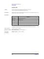
Typeface Conventions
sample (bold)
Boldface type is used for emphasis.
sample (Italic)
Italic type is used for emphasized phrases and
titles of manuals in English.
[sample]
Indicates the key on the front panel labeled
“sample”. It also may refer to the label on the
2
button.
sample
Indicates the menu, button, or box labeled
“sample”, which can be clicked to carry out the
settings and choice.
Menu indicates menu bar, pull-down menu, and
short-cut menu.
Button refers to the buttons in dialog box and
setup toolbar.
Box indicates the spin box, drop-down list box,
text box, and list box.
SAMPLE
Indicates the block or toolbar labeled
“SAMPLE“.
Block indicates the key group on the front panel.
Tool bar indicates the setup toolbar (the group of
buttons and boxes on the setup screen displayed in
the right row).
s1 - s2 - s3 - s4
Indicates a series of operations using the menu or
key labeled “s1“,”s2” and the button or box in the
setup toolbar labeled “s3”,” s4”.
Sample Program Disk
Sample program disks (Agilent Part Number E4991-180x0) are furnished with this
manual. The disk contains the sample programs used in this manual.
The customer shall have the personal, non-transferable rights to use, copy, or modify
SAMPLE PROGRAMS in this manual for the Customer’s internal operations. The
customer shall use the SAMPLE PROGRAMS solely and exclusively for their own
purposes and shall not license, lease, market, or distribute the SAMPLE PROGRAMS or
modification of any part thereof.
Agilent Technologies shall not be liable for the quality, performance, or behavior of the
SAMPLE PROGRAMS. Agilent Technologies especially disclaims any responsibility for
the operation of the SAMPLE PROGRAMS to be uninterrupted or error-free. The
SAMPLE PROGRAMS are provided AS IS.
AGILENT TECHNOLOGIES DISCLAIMS ANY IMPLIED WARRANTY OF
MERCHANTABILITY AND FITNESS FOR A PARTICULAR PURPOSE.
Agilent Technologies shall not be liable for any infringement of any patent, trademark,
copyright, or other proprietary right by the SAMPLE PROGRAMS or their use. Agilent
Technologies does not warrant that the SAMPLE PROGRAMS are free from
infringements of such rights of third parties. However, Agilent Technologies will not
knowingly infringe or deliver software that infringes the patent, trademark, copyright, or
other proprietary right of a third party.
3
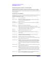
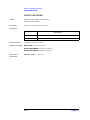
E4991A Documentation Map
The following manuals are available for the Agilent E4991A.
•
Operational Manual (Part Number: E4991-900x0, attached to optional ABA)
This manual describes most of the basic information necessary to use the E4991A. It
provides a function overview, detailed operation procedure for each function (from
preparation for measurement to analysis of measurement results), measurement
examples, specifications, and supplemental information. For programming guidance on
performing automatic measurement with the E4991A, please see the Programming
Manual.
•
Installation and Quick Start Guide (Part Number: E4991-902x1, attached to
optional ABA)
This manual describes installation after it is delivered and the basic operation
procedures for applications and analysis. Refer to this manual when you use the
E4991A for the first time.
•
Programming Manual (Part Number: E4991-900x2, attached to optional ABA)
This manual provides programming information for performing automatic
measurement with the E4991A. It includes an outline of remote control, procedures for
detecting measurement start (trigger) and end (sweep end), application programming
examples, command reference, and related information.
NOTE
The number position shown by “x” in the part numbers above indicates the edition number.
This convention is applied to each manual, CD-ROM (for manuals), and sample programs
disk issued. Here, “0” indicates the initial edition, and each time a revision is made this
number is incremented by 1. The latest edition allows the customer to specify Option ABA
(English version).
4
To Make Effective Use of This Manual 19
Contents of this manual 20
How to use this manual 23
Selecting the structure of remote control system 23
Sample programs 24
Outline of Remote Control 25
Outline of GPIB remote control system 26
System structure 26
Sending GPIB command messages 29
Remote control using E4991A macros 32
System structure 32
How to operate macros 33
Sending command messages 34
Remote mode 34
Remote control using remote user interface function and application software 35
System structure 35
How to use the application software 36
Sending command messages 37
Remote mode 37
Setting Measurement Conditions 39
Set Measurement Parameter 40
Measurement Mode 40
Display Trace 40
Parameters for Scalar Trace 41
Phase Display for Scalar Trace 42
Parameters for Complex Trace 43
Set Sweep Conditions 44
Select Sweep Parameter 44
Set Number of Measurement Points 44
Set Sweep Direction 44
Set Sweep Range 45
Set Sweep Time 47
Set Delay Time 47
Set Frequency Span (only segment sweep) 47
Set Measurement Source 48
Set Source 48
Set DC Bias (DC Bias Function) 49
Set Averaging 50
Sweep Averaging 50
Point Averaging 50
Set Display Scale 51
Select Trace for Which Scale Is Set 51
Automatic Scale Adjustment 51
Manual Setting of Scale 51
Example program for setting the measuring conditions 54
5
Example program using HTBasic 55
Example program using macro (E4991A VBA) 59
Combination of Several Sweep Conditions (Segment Sweep) 64
Create/Edit Segment Sweep Table 64
Example program for setting the segment sweep conditions 66
Example program using HTBasic 66
Example program using macro (E4991A VBA) 70
Preparation for Accurate Measurement 73
Calibration 74
Define Calibration Kit 74
Define Load Standard Value Used for Measurement of Dielectric Material 75
Select Calibration Data Measurement Points 75
Measure Calibration Data 76
Calibration Data Array/Calibration Coefficient Array 77
Example program for execution of calibration 78
Example program for calibration coefficient transfer 87
Electrical Length Compensation 91
Test Fixture 91
Add Offset Delay Time (Port Extension Compensation) 92
Fixture Compensation 93
Define Fixture Compensation Kit 93
Select Fixture Compensation Data Measurement Points 94
Measure Fixture Compensation Data 95
Fixture Compensation Data Array/Fixture Compensation Coefficient Array 96
Example program for execution of fixture compensation 97
Measurement Start and Detection of Measurement End 107
Measurement Trigger (Measurement Start) 108
Trigger System 108
Trigger Measurement 111
Waiting for Measurement End (Detection of Sweep End) 112
Using the Status Register 112
Adding Wait Time 113
Example Programs for Detecting Measurement End 114
Example program using HTBasic (SRQ) 114
Example program using macro (E4991A VBA) 116
Read and Write Measurement Data 119
Data Transfer Format 120
ASCII Format 120
IEEE 32-Bit Floating Point Format 121
IEEE 64-Bit Floating Point Format 122
Specify Byte Order (Binary Transfer) 122
Internal Data Flow 123
Data Processing Flow 123
Internal Data Arrays 123
Timing for read/write 128
6
Example Programs for Reading Internal Data Arrays 129
Reading the data trace array (ASCII format) 129
Reading the dc bias level monitor array 133
Measurement Result Processing 139
Using Marker Function 140
Markers 140
Moving Markers and Reading at Marker Positions 141
Setting Δ Mode 142
Entering Marker Values as E4991A Setting 143
Marker Search Function 144
Limit Test Function 147
Statistical Analysis Function 149
Example Programs for Marker Search Function 150
Example Programs for Marker Limit Test Function 159
Equivalent Circuit Analysis 167
Selecting an Equivalent Circuit Model 167
Performing Equivalent Circuit Analysis 168
Simulating Frequency Characteristics 168
Example Programs for Equivalent Circuit Analysis 169
Save and Recall Files 175
Saving and Recalling Files 176
Current Folder 176
Saving Files 177
Recalling Files 178
Automatic Recall of State File 178
Folder and File Manipulation 179
Folders 179
Files 179
Example Programs for Saving/Recalling a File 180
Example program using HTBasic 180
Example program using macro (E4991A VBA) 187
Using Printer 195
Printing out to a Printer Connected to E4991A 196
Selecting Print Contents 196
Selecting Color 196
Performing Printout 196
Cancelling Printing 196
Setting the Display 197
Setting the Display 198
GPIB Commands for Entire Screen (windows) 198
GPIB Commands for Traces 198
When Data Trace Is Refreshed 200
Refresh for Each Sweep 200
Refresh for Each Measurement Point 200
Refresh Periodically 200
7
Error Handling 201
Using the Error Queue 202
Using Status Report Mechanism 203
Example Program for Error Handling 204
Using HTBasic 204
Using the macro (E4991A VBA) 206
Shutting Down the Instrument 209
Shutdown Procedure 210
Use of Macros 211
Overview of Macros 212
Macro Function Overview 213
Starting Up and Closing Visual Basic Editor 214
Starting up Visual Basic Editor 214
Quitting Visual Basic Editor 214
Displaying the E4991A measurement screen 214
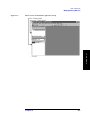
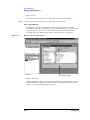
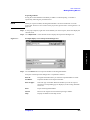
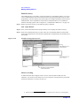
Making/Editing Macros 215
Elements of Visual Basic Editor 215
Describing macros 226
E4991A Library 228
Macro recording 228
Debugging macros 229
Executing and Terminating Macros 230
Executing macros 230
Executing macros by GPIB commands 231
Terminating macros 231
Saving/Loading Macros 232
Saving macros 232
Loading macros 233
Using E4991A VBA Help 234
Displaying the E4991A VBA help screen 234
Displaying topics of E4991A VBA 235
Referring to contents of keywords 235
Outline of Programming Using COM 237
Outline of E4991A COM 238
E4991A COM Object 238
Limitations on using the E4991A COM object 239
Comparison of COM objects and GPIB commands 239
E4991A COM Object Model 242
Application Object 242
SCPI Object 243
E4991A Library 244
Where to install the E4991A library 244
Controlling Peripherals 245
Overview 246
Preparation 246
8
Programming with VISA 247
STEP 1. Starting up VISA system 248
STEP 2. Connection 248
STEP 3. Communication 249
STEP 4. Disconnection 250
Application program using DC power supply (Agilent E3631A) 251
Application Programs 253
Basic Measurement 254
HTBasic example program 254
Macro (E4991A VBA) Example Program 264
GPIB Command Reference 275
Conventions 276
Format 276
Description 276
Parameters 277
Query response 278
Related command(s) 278
Front Panel Equivalents 278
IEEE subsystem 279
*CLS 279
*ESE 280
*ESR? 280
*IDN? 281
*OPC 281
*OPC? 281
*OPT? 282
*RST 282
*SRE 283
*STB? 283
*TRG 284
*TST? 284
*WAI 284
E4991A GPIB command 286
ABOR 286
AVER 287
AVER:COUN 288
CALC:AVER 289
CALC:AVER:CLE 289
CALC:AVER:COUN 290
CALC:BMON 291
CALC:DATA:MON? 292
CALC{1-5}:DATA? 293
CALC{1-5}:DATA:EPAR 294
CALC{1-5}:EPAR 295
CALC{1-5}:EPAR:CIRC 296
9
CALC{1-5}:EPAR:SIM 297
CALC{1-5}:FORM 298
CALC:FORM:PAR:DIE 300
CALC{1-3}:FORM:PAR:EPH 301
CALC:FORM:PAR:MAG 302
CALC{1-5}:FORM:UNIT:ANGL 303
CALC{1-5}:MARK{1-8} 304
CALC{1-5}:MARK{1-8}:ACT 305
CALC{1-5}:MARK:AOFF 305
CALC{1-5}:MARK:APE:SET 306
CALC{1-5}:MARK:APE:EXC:X 307
CALC{1-5}:MARK:APE:EXC:Y 308
CALC:MARK:COUP 309
CALC{1-5}:MARK:DISC 309
CALC{4-5}:MARK:FORM 310
CALC{1-5}:MARK:FUNC 311
CALC{1-5}:MARK:FUNC:DOM 312
CALC{1-5}:MARK{1-8}:FUNC:DOM:LIM 313
CALC{1-5}:MARK:FUNC:DOM:LIM:ALL 314
CALC{1-5}:MARK:FUNC:DOM:LIM:ALL:RES? 315
CALC{1-5}:MARK{1-8}:FUNC:DOM:LIM:LOW 316
CALC{1-5}:MARK{1-8}:FUNC:DOM:LIM:RES? 317
CALC{1-5}:MARK{1-8}:FUNC:DOM:LIM:UP 318
CALC{1-5}:MARK:FUNC:DOM:SPAN 319
CALC{1-5}:MARK:FUNC:DOM:STAR 320
CALC{1-5}:MARK:FUNC:DOM:STOP 320
CALC{1-5}:MARK:FUNC:EXEC 321
CALC{1-5}:MARK:FUNC:EXEC:LEFT 322
CALC{1-5}:MARK:FUNC:EXEC:NEXT 322
CALC{1-5}:MARK:FUNC:EXEC:RIGH 323
CALC{1-5}:MARK:FUNC:TARG 324
CALC{1-5}:MARK:FUNC:TRAC 325
CALC{1-5}:MARK:LIST 326
CALC{1-5}:MARK:ON 327
CALC{1-5}:MARK:REF 328
CALC{1-5}:MARK:REF:ACT 329
CALC{1-5}:MARK:REF:FUNC:DOM:LIM 329
CALC{1-5}:MARK:REF:FUNC:DOM:LIM:LOW 330
CALC{1-5}:MARK:REF:FUNC:DOM:LIM:RES? 331
CALC{1-5}:MARK:REF:FUNC:DOM:LIM:UP 332
CALC{1-5}:MARK:REF:TYPE 333
CALC{1-5}:MARK:REF:X 334
CALC{1-5}:MARK:REF:Y 335
CALC{1-5}:MARK:SET 336
CALC{1-5}:MARK:UNIT 337
10
CALC{1-5}:MARK{1-8}:X 338
CALC{1-5}:MARK{1-8}:Y? 339
CALC{1-5}:MATH:FUNC 340
CALC{1-5}:MATH:MEM 341
CALC{1-3}:MATH:OFFS 342
CALC{1-5}:MST 343
CALC{1-5}:MST:DATA? 344
DATA:CAD{1-8}? 345
DATA:CCO{1-6} 346
DATA:CMD{1-2}? 347
DATA:CMP{1-3} 348
DATA:RAW? 349
DATA:SEGM{1-16}:CAD{1-8}? 350
DATA:SEGM{1-16}:CCO{1-6} 351
DATA:SEGM{1-16}:CMD{1-2}? 352
DATA:SEGM{1-16}:CMP{1-3} 353
DISP:BACK 354
DISP:ENAB 354
DISP:FORM 355
DISP:TEXT 355
DISP:TEXT{1-3}:SET 356
DISP:TRAC{1-5} 356
DISP:TRAC{1-5}:GRAT:FORM 357
DISP:TRAC{1-3}:REF 358
DISP:TRAC{1-5}:SEL 358
DISP:TRAC{1-5}:TEXT 359
DISP:TRAC{1-5}:TEXT:PAGE 359
DISP:TRAC{1-5}:TITL 360
DISP:TRAC{1-5}:TITL:DATA 361
DISP:TRAC{4-5}:X:RLEV 362
DISP:TRAC{1-5}:X:SPAC 363
DISP:TRAC{1-5}:Y:AUTO 364
DISP:TRAC:Y:AUTO:ALL 364
DISP:TRAC{1-3}:Y:BOTT 365
DISP:TRAC{1-5}:Y:FOR 366
DISP:TRAC{1-5}:Y:FULL 367
DISP:TRAC{1-5}:Y:PDIV 368
DISP:TRAC{1-5}:Y:RLEV 369
DISP:TRAC{1-3}:Y:RPOS 370
DISP:TRAC{1-3}:Y:SPAC 371
DISP:TRAC{1-3}:Y:TOP 372
FORM:BORD 373
FORM:DATA 374
FREQ 375
FREQ:CENT 376
11
FREQ:SPAN 377
FREQ:SPAN:FULL 377
FREQ:STAR 378
FREQ:STOP 379
HCOP 380
HCOP:ABOR 380
HCOP:CONT 380
HCOP:IMAG 381
INIT 382
INIT:CONT 382
MMEM:CAT? 383
MMEM:CDIR 383
MMEM:COPY 384
MMEM:DEL 384
MMEM:LOAD 385
MMEM:LOAD:MACR 385
MMEM:LOAD:TRAC 386
MMEM:MDIR 386
MMEM:MOVE 387
MMEM:RDIR 388
MMEM:STOR 388
MMEM:STOR:CITI{1-3} 389
MMEM:STOR:GRAP 389
MMEM:STOR:GRAP:BMP 390
MMEM:STOR:MACR 390
MMEM:STOR:TRAC 391
MMEM:STOR:TRAC:ASC 391
MMEM:STOR:TRAC:SEL{1-4} 392
MODE 393
PROG:CAT? 394
PROG:NAME 394
PROG:STAT 395
PROG:WAIT 395
SEGM{1-16}:AVER:COUN 396
SEGM:COUN 397
SEGM{1-16}:CURR 398
SEGM:CURR:OFFS:STAT 399
SEGM{1-16}:CURR:LIM 400
SEGM{1-16}:CURR:OFFS 401
SEGM:CURR:STAT 402
SEGM{1-16}:DATA 403
SEGM:DATA:ALL 405
SEGM:DEL:ALL 406
SEGM{1-16}:FREQ:CENT 407
SEGM{1-16}:FREQ:SPAN 408
12
SEGM{1-16}:FREQ:STAR 409
SEGM{1-16}:FREQ:STOP 410
SEGM{1-16}:POW 411
SEGM:POW:STAT 412
SEGM{1-16}:SWE:POIN 413
SEGM{1-16}:VOLT 414
SEGM{1-16}:VOLT:LIM 415
SEGM{1-16}:VOLT:OFFS 416
SEGM:VOLT:OFFS:STAT 417
SEGM:VOLT:STAT 418
SENS:CORR1 419
SENS:CORR1:CKIT 420
SENS:CORR1:CKIT:LIST 421
SENS:CORR1:CKIT:STAN1:C 422
SENS:CORR1:CKIT:STAN1:G 423
SENS:CORR1:CKIT:STAN1:LIST:B 424
SENS:CORR1:CKIT:STAN1:LIST:G 425
SENS:CORR1:CKIT:STAN2:L 426
SENS:CORR1:CKIT:STAN2:LIST:R 427
SENS:CORR1:CKIT:STAN2:LIST:X 428
SENS:CORR1:CKIT:STAN2:R 429
SENS:CORR1:CKIT:STAN3:L 430
SENS:CORR1:CKIT:STAN3:LIST:R 431
SENS:CORR1:CKIT:STAN3:LIST:X 432
SENS:CORR1:CKIT:STAN3:R 433
SENS:CORR1:CKIT:STAN7:PLF 434
SENS:CORR1:CKIT:STAN7:PRE 435
SENS:CORR1:CKIT:STAN7:THIC 436
SENS:CORR1:COLL 437
SENS:CORR1:COLL:FPO 438
SENS:CORR1:COLL:SAVE 439
SENS:CORR2:CKIT:LIST 440
SENS:CORR2:CKIT:STAN1:C 441
SENS:CORR2:CKIT:STAN1:G 442
SENS:CORR2:CKIT:STAN1:LIST:B 443
SENS:CORR2:CKIT:STAN1:LIST:G 444
SENS:CORR2:CKIT:STAN2:L 445
SENS:CORR2:CKIT:STAN2:LIST:R 446
SENS:CORR2:CKIT:STAN2:LIST:X 447
SENS:CORR2:CKIT:STAN2:R 448
SENS:CORR2:COLL 449
SENS:CORR2:COLL:FPO 450
SENS:CORR2:COLL:OPEN 451
SENS:CORR2:COLL:SAVE 451
SENS:CORR2:COLL:SHOR 452
13
SENS:CORR2:EDEL:TIME 453
SENS:CORR2:FIXT 454
SENS:CORR2:FIXT:EDEL:MODE:DIST? 455
SENS:CORR2:FIXT:EDEL:USER:DIST 456
SOUR:CURR 457
SOUR:CURR:CENT 458
SOUR:CURR:LIM:OFFS 459
SOUR:CURR:MODE 460
SOUR:CURR:OFFS 461
SOUR:CURR:OFFS:CENT 462
SOUR:CURR:OFFS:SPAN 463
SOUR:CURR:OFFS:STAR 464
SOUR:CURR:OFFS:STAT 465
SOUR:CURR:OFFS:STOP 466
SOUR:CURR:SPAN 467
SOUR:CURR:STAR 468
SOUR:CURR:STOP 469
SOUR:POW 470
SOUR:POW:CENT 471
SOUR:POW:MODE 472
SOUR:POW:SPAN 473
SOUR:POW:STAR 474
SOUR:POW:STOP 475
SOUR:VOLT 476
SOUR:VOLT:CENT 477
SOUR:VOLT:LIM:OFFS 478
SOUR:VOLT:MODE 479
SOUR:VOLT:OFFS 480
SOUR:VOLT:OFFS:CENT 481
SOUR:VOLT:OFFS:SPAN 482
SOUR:VOLT:OFFS:STAR 483
SOUR:VOLT:OFFS:STAT 484
SOUR:VOLT:OFFS:STOP 485
SOUR:VOLT:SPAN 486
SOUR:VOLT:STAR 487
SOUR:VOLT:STOP 488
STAT:OPER? 489
STAT:OPER:COND? 489
STAT:OPER:ENAB 490
STAT:OPER:NTR 491
STAT:OPER:PTR 492
STAT:PRES 493
STAT:QUES? 493
STAT:QUES:COND? 493
STAT:QUES:ENAB 494
14
STAT:QUES:HARD? 495
STAT:QUES:HARD:COND? 495
STAT:QUES:HARD:ENAB 496
STAT:QUES:HARD:NTR 497
STAT:QUES:HARD:PTR 498
STAT:QUES:LIM? 499
STAT:QUES:LIM:COND? 499
STAT:QUES:LIM:ENAB 500
STAT:QUES:LIM:NTR 501
STAT:QUES:LIM:PTR 502
STAT:QUES:NTR 503
STAT:QUES:PTR 504
STAT:QUES:SEAR? 504
STAT:QUES:SEAR:COND? 505
STAT:QUES:SEAR:ENAB 505
STAT:QUES:SEAR:NTR 506
STAT:QUES:SEAR:PTR 507
SWE:DIR 508
SWE:DWEL1 508
SWE:DWEL2 509
SWE:DWEL3 510
SWE:POIN 511
SWE:STIM{1-4}? 512
SWE:TIME 513
SWE:TIME:AUTO 514
SWE:TYPE 515
SYST:BEEP 516
SYST:BEEP:STAT 516
SYST:DATE 517
SYST:ERR? 517
SYST:ERR:COUN? 518
SYST:EXTR? 518
SYST:IND:POIN:SET 519
SYST:IND:SWE:SET 519
SYST:IND:TIME 520
SYST:IND:TIME:SET 521
SYST:KLOC 522
SYST:KLOC:KBD 522
SYST:KLOC:MOUS 523
SYST:POFF 523
SYST:PRES 523
SYST:TIME 524
SYST:VERS? 524
TRIG 525
TRIG:EVEN 525
15
TRIG:SLOP 526
TRIG:SOUR 526
COM Interface Reference 527
Conventions of COM Interface 528
Explanation 528
VB Syntax 528
Parameter 528
Response 529
Examples 529
Application object 530
Name property 530
VBAVersion property 530
Connection property 531
SingleMeasure method 532
CalMeasure method 533
CompenMeasure method 534
GetTextData method 535
GetScreenImage method 535
WaitForEvent method 536
SweepEnd event 537
SweepStart event 538
CompleteSweepAveraging event 538
Unlocked event 539
DcBiasOverload event 539
RfOverload event 540
SCPI object 541
Name property 541
Enter method 542
Output method 543
Query method 543
How to read array data 544
Option parameters offered in Enter method 544
Not specifying option parameter 544
Specifying option parameters 546
Manual Changes 549
Manual Changes 550
Change 1 550
Change 2 552
GPIB Status Report System 555
General Model of Status Registers 556
Event Registers 557
Enable Registers 557
Status Byte Register 558
Transition Filter and Condition Register 559
Status Register Structure 560
16
GPIB Command List By Function 569
GPIB Command List By Function 570
Table of corresponding 4291B vs. E4991A GPIB commands 581
Table of Corresponding GPIB Commands 582
Complex Operation Programs 601
Complex Operation Programs 602
Sample Implementation in Visual Basic 602
Sample Implementation in HTBasic 603
List of Responses to Measurement Failure 605
Behavior under Abnormal Measurement Conditions 606
Messages 607
Order of Error Number 608
Messages indicating the internal status of the equipment 620
Messages indicating the measurement failure 620
Messages indicating the results of processing (elapsing) 621
17
18
1. To Make Effective Use
of This Manual
1
To Make Effective Use of This Manual
This chapter describes the contents of this programming manual and how to use it.
19
To Make Effective Use of This Manual
Contents of this manual
Contents of this manual
This is the programming manual of the E4991A RF Impedance/Material Analyzer. The
contents of each chapter in this manual are as follows.
Chapter 1, “To Make Effective Use of This Manual”
This chapter describes the contents of this programming manual and how to use it.
Chapter 2, “Outline of Remote Control”
This chapter explains the system structures, required equipment, and set up methods
needed to structure the remote control system of the E4991A.
Chapter 3, “Setting Measurement Conditions”
This chapter explains how to set the measurement conditions of the Agilent E4991A.
Chapter 4, “Preparation for Accurate Measurement”
This chapter explains how to perform calibration as well as electrical length and
fixture compensation for the Agilent E4991A.
Chapter 5, “Measurement Start and Detection of Measurement End”
This chapter explains how to prepare a trigger for starting measurement and
detecting the end of measurement with the Agilent E4991A.
Chapter 6, “Read and Write Measurement Data”
This chapter explains how to read and write Agilent E4991A measurement data.
Chapter 7, “Measurement Result Processing”
This chapter explains how to process measurement results by using the Agilent
E4991A’s marker function and equivalent circuit analysis function.
Chapter 8, “Save and Recall Files”
This chapter explains how to save the Agilent E4991A’s measurement condition
settings or measurement results to a file and how to later recall them from the file.
Chapter 9, “Using Printer”
This chapter explains how to use a printer connected to the Agilent E4991A to print
out measurement results and other information from the instrument.
Chapter 10, “Setting the Display”
This chapter explains how to set the display screen of the Agilent E4991A.
Chapter 11, “Error Handling”
This chapter describes how the Agilent E4991A handles errors in program execution.
Chapter 12, “Shutting Down the Instrument”
This chapter explains how to properly shut down the Agilent E4991A.
20
Chapter 1
Chapter 13, “Use of Macros”
This chapter explains how to use the macro function of the Agilent E4991A to create
macro programs with the Visual Basic editor. Information is also given on how to
execute produced macros.
Chapter 14, “Outline of Programming Using COM”
This chapter gives the required information for programming with the COM
interface of the Agilent E4991A. For more basic information on the COM interface,
refer to Chapter 18, “COM Interface Reference.”
Chapter 15, “Controlling Peripherals”
This chapter explains how to control peripherals connected to the Agilent E4991A by
using the software (VISA) installed in the instrument.
Chapter 16, “Application Programs”
This chapter gives measurement examples (sample programs) using the HTBasic
program and the instrument’s macro program (E4991A VBA).
Chapter 17, “GPIB Command Reference”
This chapter provides the GPIB command reference of the Agilent E4991A. The
command references are written in abbreviated form and listed in alphabetic order.
Chapter 18, “COM Interface Reference”
This chapter gives COM interface references of the Agilent E4991A classified
according to object.
Appendix A, “Manual Changes”
This appendix contains the information required to adapt this manual to versions or
configurations of the Agilent E4991A manufactured earlier than the current printing
date of this manual. The information contained elsewhere in this manual applies
directly to E4991A units bearing the serial number printed on this manual’s title
page.
Appendix B, “GPIB Status Report System”
This appendix describes the status report system in the Agilent E4991A GPIB
system.
Appendix C, “GPIB Command List By Function”
This appendix lists the Agilent E4991A GPIB commands according to function.
Appendix D, “Table of corresponding 4291B vs. E4991A GPIB commands”
This appendix lists each Agilent E4991A GPIB command along with its
corresponding Agilent 4291B GPIB command. Note that the simple commands
prepared for the 4291B do not have equivalent E4991A commands.
Appendix E, “Complex Operation Programs”
This appendix shows sample programs for implementing complex operations in
Visual Basic and HTBasic.
Chapter 1
21
1. To Make Effective Use
of This Manual
To Make Effective Use of This Manual
Contents of this manual
To Make Effective Use of This Manual
Contents of this manual
Appendix F, “List of Responses to Measurement Failure”
This appendix lists the Agilent E4991A’s responses to various types of measurement
failure.
Appendix G, “Messages”
The Agilent E4991A provides error messages as well as messages that indicate the
internal operating status of the equipment. This appendix describes such messages in
order of error number. To search for E4991A error messages in alphabetical order,
please refer to the Operation Manual.
22
Chapter 1
How to use this manual
When writing programs, it is not necessarily required to use all the information in this
manual. Basically, the structure of remote control system that the user decides will
determine required equipment, programming language that is necessary to understand, and
command set to control the E4991A.
Selecting the structure of remote control system
First, select the remote control system to suit the purpose from the following remote
control system structures, and read this manual according to the contents written there.
1. Manual operation
Operating the E4991A through the front panel of the E4991A or keyboard/mouse. This
doesn’t suit the measurement of complex setting combination while it doesn’t require
the preparation of external controller separately or the knowledge of programming to
control the E4991A. Refer to the operation manual for how to operate E4991A through
the front panel or keyboard/mouse.
2. Manual operation using remote user interface function
If remote user interface function is used, it becomes possible to operate the E4991A
from Personal Computer by providing the environment of the E4991A user interface
(keyboard/mouse connected to the E4991A) for the Personal Computer connected to
the E4991A on LAN. Refer to the operation manual for the set-up and usage of remote
user interface function.
3. GPIB remote control system
The E4991A can be controlled from external controller (for example, computers like a
Personal Computer, Work Station, etc.) through GPIB interface. The outline of the
system is explained in “Outline of GPIB remote control system” on page 26.
4. Remote control using macros in the E4991A
The E4991A and peripheral equipment can be controlled by using the macros (Visual
Basic for Application) which is installed in the E4991A. The outline of the system is
explained in “Remote control using E4991A macros” on page 32.
5. Remote control using remote user interface function and application software.
The E4991A can be controlled from the Personal Computer that is connected to the
E4991A by the remote user interface function, using application software (Microsoft
Visual Basic, and etc.). The outline of the system is explained in “Remote control using
remote user interface function and application software” on page 35.
Chapter 1
23
1. To Make Effective Use
of This Manual
To Make Effective Use of This Manual
How to use this manual
To Make Effective Use of This Manual
How to use this manual
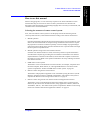
Sample programs
The sample program disk (Agilent Parts No. E4991-180x0) and CD-ROM (Agilent Parts
No. E4991-905x0) contain HTBasic sample programs and E4991A VBA sample programs
shown in this manual. These sample program disks are DOS formatted.
How to load the sample program
To use the sample program on HTBasic, load it by GET command on HTBasic. The
following is an example of loading a sample program, "setup.htb".
GET "setup.htb"
To use the sample program on the E4991A VBA which file extension is *.lcr, load the
macro program after the following front panel operation from the E4991A.
Utility - Load Program...
Or, to use the sample program on the E4991A VBA which file extension is *.bas or *.cls,
import the macro program from the Visual Basic Editor.
24
Chapter 1
2. Outline of Remote Control
2
Outline of Remote Control
This chapter explains the system structures, required equipment, and set up methods
needed to structure the remote control system of the E4991A.
25
Outline of Remote Control
Outline of GPIB remote control system
Outline of GPIB remote control system
This section explains the system structures and required equipment for sending GPIB
command messages. In Chapter 17, you can also find more on the GPIB commands used to
control the E4991A from an external computer through the GPIB interface.
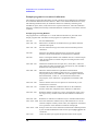
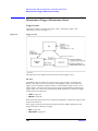
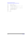
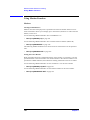
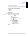
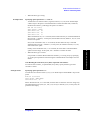
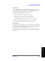
System structure
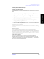
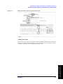
Connect the E4991A to an external computer and peripheral equipment with a GPIB cable.
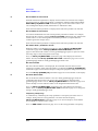
Figure 2-1 outlines the system structure for the GPIB remote control system.
Figure 2-1
Structure example of GPIB remote control system
What is GPIB?
GPIB (General-Purpose Interface Bus) is an interface standard for connecting computers
and peripheral equipment. It supports worldwide standards such as IEEE 488.1, IEC-625,
IEEE 488.2 and JIS-C1901. By using the GPIB interface, the E4991A can be controlled
from an external computer. The computer sends commands and instructions to the E4991A
and receives data sent from it through GPIB.
26
Chapter 2
Outline of Remote Control
Outline of GPIB remote control system
Required equipment
1. The Agilent E4991A RF Impedance/Material Analyzer and the accessories required to
measure a DUT
a. Set the GPIB address of the E4991A.
System - GPIB Setup... - E4991A Address: (drop-down box)
b. Turn the E4991A’s main power off and then back on again.
2. GPIB system controller
To use an external computer as the system controller, a Personal
Computer (IBM compatible) or work station with a GPIB
interface is required. Also, software such as Agilent VEE,
Microsoft Visual Basic, or HTBasic is required to control the
E4991A through GPIB.
3. Peripheral equipment depending on the user’s purpose
4. GPIB cable (10833A/B/C/D) to connect the computer to the E4991A and peripheral
equipment
Chapter 2
27
2. Outline of Remote Control
It is not necessary to select the system-controller mode or the
addressable-only mode of the GPIB system. The E4991A is
automatically set to appropriate mode by the controller when the
GPIB program is run.
Outline of Remote Control
Outline of GPIB remote control system
The sizes and configurations of possible GPIB systems
•
A maximum of 15 devices can be connected to one GPIB system.
•
Keep the length of cable between devices within 1 m. The total length of connecting
cable in a single GPIB system should not exceed 2 m × the number of connected
devices (the controller is counted as one device). Also, you cannot construct a system
having more than 20 m in total cable length.
•
The number of connectors on a single device should not exceed 4. More than that will
cause strain on the connector parts, which could lead to equipment breakdown.
•
The pattern of connection can be star topology, linear topology or a combination of
both. However, loop topology cannot be used.
Controller
The device that allows talk (data output) or listen (data receipt) by the GPIB device is
called the controller.
An active controller can control other devices on the bus (if multiple controllers are
connected). Only one controller can be active at any one time. By executing the pass
control, the active controller can pass the controlling right to another controller (pass
control function).
NOTE
When the E4991A is used in system controller mode, the controlling right cannot be passed
to another controller or cannot be received from another computer because the E4991A
does not support the pass control function.
Device selector
Device control of GPIB is performed by sending a command by the active controller. The
active controller can choose the target device by specifying the device selector.
28
Chapter 2
Outline of Remote Control
Outline of GPIB remote control system
Sending GPIB command messages
Learning about GPIB commands
To find information on a particular GPIB command, refer to the following sections in this
book.
The procedures used to write basic programs for the E4991A are explained from
Chapter 2 to Chapter 11. Program examples using HTBasic are also given.
•
Appendix C, “GPIB Command List By Function,” on page 569 provides a convenient
list of GPIB commands according to the measurement or general-purpose functions
they perform.
•
“List of Functions by Menu” in the Operation Manual shows the correspondence of
GPIB Commands to the front panel operation of the E4991A.
•
Chapter 16, “Application Programs,” on page 253 shows E4991A application
examples produced by using HTBasic.
•
Chapter 17, “GPIB Command Reference,” on page 275 lists all of the GPIB commands
used with the E4991A in alphabetical order.
Type and structure of commands
The GPIB commands that can be used with the E4991A are classified into the following
two groups.
E4991A commands
These commands are unique to the E4991A. They cover all of the instrument’s
measurement functions and some of its general-purpose functions. The commands in this
group have a hierarchical structure called a command tree. Each command is structured by
a character string (mnemonic) to indicate the hierarchy and uses a colon (:) as a divisional
marker between hierarchical levels.
IEEE common commands
These are the commands used to cover the general purpose functions defined by
IEEE488.2. These can be commonly used by measurement equipment that support this
standard. The commands in this group always start with an asterisk (*). The commands in
this group do not have a hierarchical structure.
Chapter 2
29
2. Outline of Remote Control
•
Outline of Remote Control
Outline of GPIB remote control system
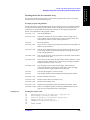
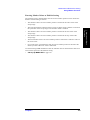
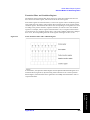
The concept of command tree
The command at the highest-level position in the command tree hierarchy is called “root
command” or simply “root.” To access a lower command in the tree structure’s hierarchy, a
particular “path” has to be specified in the same way as a directory path in the DOS file
system. The current path is set as “root” after the power is turned on or a reset is executed.
Depending on the special symbols in the massage, the setting of the path changes as
follows.
Message terminator
A message terminator such as <new line> sets the current path as the
“root.”
Colon (:)
When a colon is located between two command mnemonics, the colon
lowers the level of the current path on the command tree. When it is
used as the first character of a command, it specifies the command
mnemonic to follow it as the command of root level.
Semi-colon (;)
A semi-colon divides two commands within one message without
changing the current path.
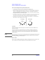
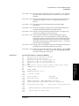
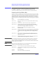
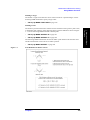
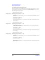
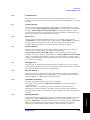
Figure 2-2 shows an example of using the colon and semi-colon for efficient access of
various commands within the command tree.
Figure 2-2
Usage of colon and semi-colon
30
Chapter 2
Outline of Remote Control
Outline of GPIB remote control system
Grammar for massages
The grammar used for sending program messages by GPIB is described below. Program
massage means a massage sent to the measurement equipment by the user through an
external computer for controlling the measurement equipment. A program message
contains one or more commands and the parameters required for them.
Handling of capital/small letters
Program message terminator
Program messages have to end with any one of these three program message terminators:
<new line>, <^END>, and <new line><^END>. <END> means that EOI becomes the
active level on the GPIB interface when the immediately preceding data byte is sent out.
For example, the OUTPUT command of HTBasic automatically sends the message
terminator after the last data byte.
Parameter
A space (ASCII code 32) is required between a command and the first parameter. When
multiple parameters are sent with one command, the parameters have to be divided by
commas (,).
Message that includes multiple commands
When sending two or more commands in one message, the commands have to be divided
by semi-colons (;). The following is an example of sending the *CLS command and the
INIT command in the same massage by HTBasic.
OUTPUT 717;"*CLS;:INIT"
Remote mode
The E4991A doesn’t have a remote mode. Therefore, it doesn’t switch to remote mode
even if it receives the relevant GPIB command. Also, there is no local key to release the
remote mode.
When it is necessary to prevent operational error caused by mistaken input through the
front panel or keyboard/mouse of the E4991A under remote control, use one of the
following GPIB commands to lock the input device.
•
SYST:KLOC on page 522 (locks front panel)
•
SYST:KLOC:KBD on page 522 (locks keyboard)
•
SYST:KLOC:MOUS on page 523 (locks mouse)
Chapter 2
31
2. Outline of Remote Control
No differentiation between capital and small letters
Outline of Remote Control
Remote control using E4991A macros
Remote control using E4991A macros
This section describes the system structures and command sets used for controlling the
E4991A and peripheral equipment with the instrument’s macro functions.
NOTE
The E4991A is shipped with a macro function. A macro allows you to automatically
execute a series of multiple commands with a single command. Using a macro allows you
to combine the steps of a complicated procedure into a single step for a wide variety of
applications. A macro can also be used to control peripheral equipment. The E4991A VBA
(Visual Basic for Application) is the programming language used to execute macro
functions.
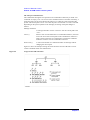
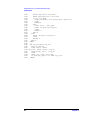
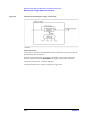
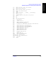
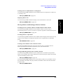
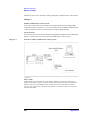
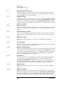
System structure
Connect the E4991A to any peripheral equipment that can be connected with a USB/GPIB
cable. An outline of a remote control system using the macro functions is shown in Figure
2-3.
Figure 2-3
Structure example of GPIB remote control system
32
Chapter 2
Outline of Remote Control
Remote control using E4991A macros
Required equipment
1. The Agilent E4991A RF Impedance/Material Analyzer and the accessories required to
measure a DUT
2. Peripheral equipment depending on the user’s purpose
3. USB/GPIB interface(82357A).
To use the VBA remote control system, you need to set the USB/GPIB interface correctly.
For detail, refer to Operation Manual.
NOTE
Do not connect two or more USB/GPIB interfaces.
Size and configuration of possible GPIB systems
For information on the type of GPIB system that can be constructed for controlling
peripheral equipment, refer to “The sizes and configurations of possible GPIB systems” on
page 28.
How to operate macros
It is necessary to understand the basics of E4991A VBA, which is the programming
language used for writing and executing macros. E4991A VBA is briefly explained in
Chapter 13, “Use of Macros,” on page 211. Refer to E4991A VBA help for more detailed
information on the basics of E4991A VBA programming, standard control, and functions.
Chapter 2
33
2. Outline of Remote Control
NOTE
Outline of Remote Control
Remote control using E4991A macros
Sending command messages
When controlling the E4991A or peripheral equipment by macro functions, the command
set differs depending on the target of control.
Commands to control E4991A
The command used to control the E4991A is written in the E4991A COM interface. The
following two types of E4991A COM interfaces can be used. For combined use of the
COM interface and a GPIB command provided by the E4991A, it is necessary to
understand how to use the GPIB command.
•
COM interface
•
COM interface combined with GPIB command of the E4991A
For the basic method of using the E4991A COM interface, refer to Chapter 14, “Outline of
Programming Using COM,” on page 237 and Chapter 18, “COM Interface Reference,” on
page 527.
To find a GPIB command provided by the E4991A, refer to “Learning about GPIB
commands” on page 29.
Commands to control peripheral equipment
The macro used to control peripheral equipment is written by using the VISA library.
For the basic method of using the functions provided by the VISA library, refer to Chapter
15 on page 245. For details on how to use the VISA library, refer to the on-line help for
VISA (accessible by opening the file named visa.hlp on the supplied CD-ROM (Agilent
Parts No. E4991-905x0)).
For how to use the GPIB commands of peripheral equipment, refer to the operation manual
of the peripheral equipment.
Remote mode
Unlike previous Agilent models, the E4991A does not have a “Remote mode” that
automatically locks up operation of the front panel’s hardkeys when it is controlled through
E4991A COM object. If necessary, the E4991A’s front panel can be locked by a command.
34
Chapter 2
Outline of Remote Control
Remote control using remote user interface function and application
software
Remote control using remote user interface function and
application software
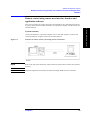
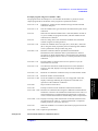
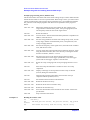
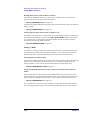
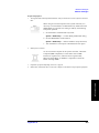
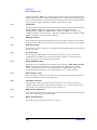
System structure
Connect the E4991A to a personal computer with a LAN cable. Figure 2-4 outlines the
system structure for using the remote user interface function.
Figure 2-4
Structure of remote control system using remote U/I function
NOTE
Refer to the Operation Manual for setup instructions of the E4991A remote user interface
function.
NOTE
Peripheral equipment connected to the E4991A through GPIB cannot be controlled.
Chapter 2
35
2. Outline of Remote Control
This section explains the system structures and command sets for controlling the E4991A
by using a macro (E4991A VBA) installed in your personal computer with the remote user
interface function.
Outline of Remote Control
Remote control using remote user interface function and application
software
Required equipment
1. The Agilent E4991A RF Impedance/Material Analyzer and the accessories required to
measure a DUT
It is not necessary to select the system-controller mode or the
addressable-only mode of the GPIB system.
2. Personal Computer
A personal computer (IBM compatible personal computer) with a
LAN interface is required.
3. LAN cable to connect the E4991A and personal computer
How to use the application software
It is necessary to understand E4991A VBA in order to install and use the supplied E4991A
VBA program on your personal computer. E4991A VBA is briefly explained in Chapter
13, “Use of Macros,” on page 211. Refer to E4991A VBA help for more detailed
information on the basics of E4991A VBA programming, standard control, and functions.
NOTE
Refer to the operation manual for instructions on installing the E4991A VBA program on
your personal computer.
NOTE
Agilent Technologies shall not guarantee operation of the E4991A COM if the customer
uses application software other than E4991A VBA (Visual Basic for Application).
36
Chapter 2
Outline of Remote Control
Remote control using remote user interface function and application
software
Sending command messages
Basically, the commands used to control the E4991A are written in the E4991A COM
interface. The following two types of E4991A COM interfaces can be used. To use the
COM interface in combination with the GPIB command offered by the E4991A, it is
necessary to understand how to use GPIB command.
COM interface
•
COM interface combined with GPIB command
For the basic method of using the E4991A COM interface, refer to Chapter 14, “Outline of
Programming Using COM,” on page 237 and Chapter 18, “COM Interface Reference,” on
page 527.
To find a GPIB command provided by the E4991A, refer to “Learning about GPIB
commands” on page 29.
Remote mode
Unlike previous Agilent models, the E4991A does not have a “Remote mode” that
automatically locks up operation of the front panel’s hardkeys when it is controlled through
E4991A COM object. If necessary, the E4991A’s front panel can be locked by a command.
Chapter 2
37
2. Outline of Remote Control
•
Outline of Remote Control
Remote control using remote user interface function and application
software
38
Chapter 2
3. Setting Measurement
Conditions
3
Setting Measurement Conditions
This chapter explains how to set the measurement conditions of the Agilent E4991A.
39
Setting Measurement Conditions
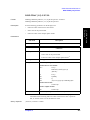
Set Measurement Parameter
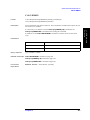
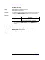
Set Measurement Parameter
The measurement mode (Impedance/Magnetic/Dielectric measurement) and the display
trace type (Scalar/Complex trace) determine the parameters available. The following
section explains how to set the measurement parameters.
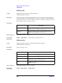
Measurement Mode
Selection
When material measurement is performed by using the E4991A with option 002 (Material
Measurement), use the following GPIB command to set the measurement mode to
magnetic measurement or dielectric measurement. The E4991A without Option 002 sets
the measurement mode to impedance.
•
MODE on page 393
Parameters for Material Measurement
Before dielectric material measurement can be performed, the following GPIB command
must be used to set the thickness of the device under test.
•
CALC:FORM:PAR:DIE on page 300
Before magnetic material measurement can be performed, the following GPIB command
must be used to set the sizes (inner and outer diameters and height) of the device under test.
•
CALC:FORM:PAR:MAG on page 302
Display Trace
The E4991A allows the user to display up to five traces. Use the following GPIB command
to display a trace.
•
DISP:TRAC{1-5} on page 356
Of the five traces, Traces 1-3 are for scalar traces and Traces 4 -5 are for complex traces.
40
Chapter 3
Setting Measurement Conditions
Set Measurement Parameter
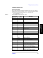
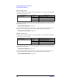
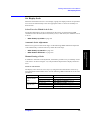
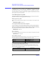
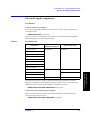
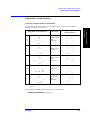
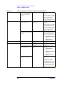
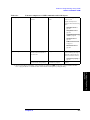
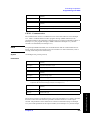
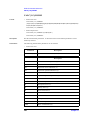
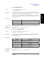
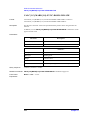
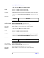
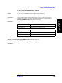
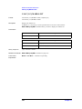
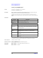
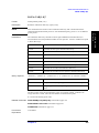
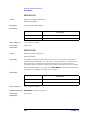
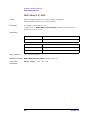
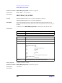
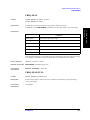
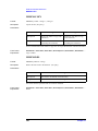
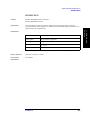
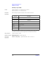
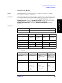
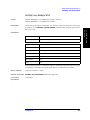
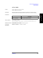
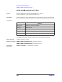
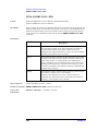
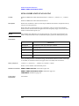
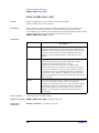
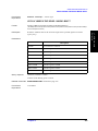
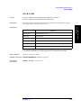
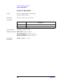
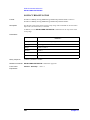
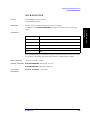
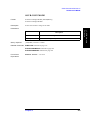
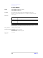
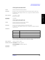
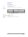
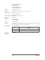
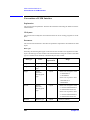
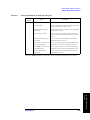
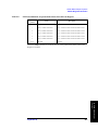
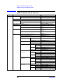
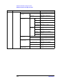
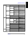
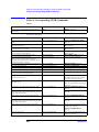
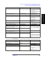
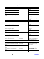
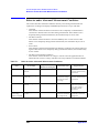
Parameters for Scalar Trace
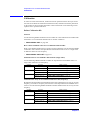
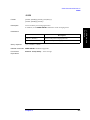
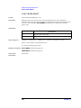
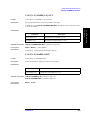
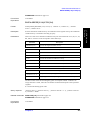
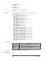
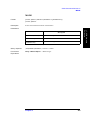
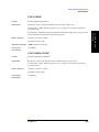
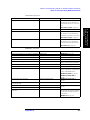
Measurement Parameters
Table 3-1 shows measurement parameters available for a scalar trace. Use the following
GPIB command to specify a trace number (1, 2, or 3) and select measurement parameters.
Note that up to three measurement parameters can be displayed at a time.
CALC{1-5}:FORM on page 298
•
Table 3-1
Measurement Parameters for Scalar Trace
Measurement
parameter
GPIB
parameter
Description
Z
Absolute value of impedance
|Y|
Y
Absolute value of admittance
Ls
LS
Equivalent serial inductance
Lp
LP
Equivalent parallel inductance
Cs
CS
Equivalent serial capacitance
Cp
CP
Equivalent parallel capacitance
Rs
RS
Equivalent serial resistance
Rp
RP
Equivalent parallel resistance
D
D
Dissipation factor
Q
Q
Quality factor (reciprocal of dissipation factor)
R
R
Serial resistance
X
X
Reactance
G
G
Conductance
B
B
Susceptance
θz
ZPH
Phase of impedance
θy
YPH
Phase of admittance
|Γ|
RC
Absolute value of reflection coefficient
θγ
RCPH
Phase of reflection coefficient
Γx
RCX
Real part of reflection coefficient
Γy
RCY
Imaginary part of reflection coefficient
|μr|
P
Absolute value of complex permeability*1
μr'
PRE
Real part of complex permeability*1
μr''
PLF
Imaginary part of complex permeability *1*1
tanδ(μ)
PLT
Magnetic loss tangent*1
|εr|
DC
Absolute value of complex permittivity*2
Chapter 3
3. Setting Measurement
Conditions
|Z|
41
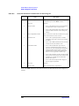
Setting Measurement Conditions
Set Measurement Parameter
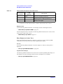
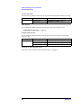
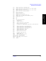
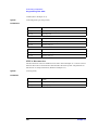
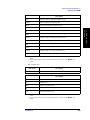
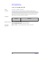
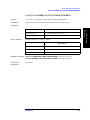
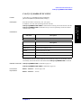
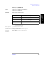
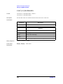
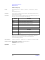
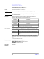
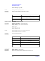
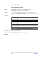
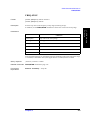
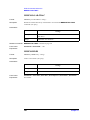
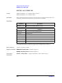
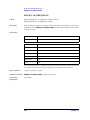
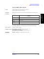
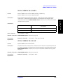
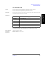
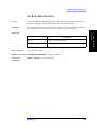
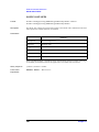
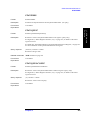
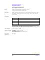
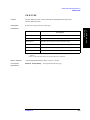
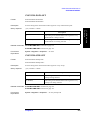
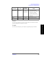
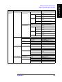
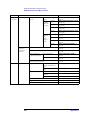
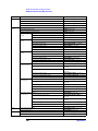
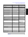
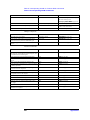
Table 3-1
Measurement Parameters for Scalar Trace
Measurement
parameter
GPIB
parameter
Description
εr'
DCR
Real part of complex permittivity*2
εr''
DCLF
Imaginary part of complex permittivity *1*2
tanδ(ε)
DCLT
Dielectric loss tangent*2
*1. Parameters selectable when the Magnetic Material measurement mode is selected.
*2. Parameters selectable when the Dielectric Material measurement mode is selected.
Display Format
Use the following GPIB command to set the display format to Rectangular format:
•
DISP:TRAC{1-5}:GRAT:FORM on page 357
If the Rectangular format is selected, the following GPIB command can be used to set the
Y-axis scale to either Liner or Log.
•
DISP:TRAC{1-3}:Y:SPAC on page 371
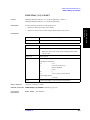
Phase Display for Scalar Trace
When the measurement parameter is phase for a scalar trace, use the following GPIB
commands to set the unit and to turn on/off expanded phase display.
Set Unit
Use the following GPIB command to set the unit (degree or radian) in which phase is
displayed:
•
CALC{1-5}:FORM:UNIT:ANGL on page 303
Expanded Phase Display
The following GPIB command can be used to turn on/off the expanded phase display (in
which phases less than -180 degree and more than +180 degree are not folded):
•
42
CALC{1-3}:FORM:PAR:EPH on page 301
Chapter 3
Setting Measurement Conditions
Set Measurement Parameter
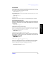
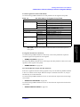
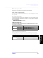
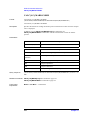
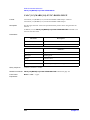
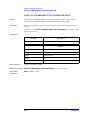
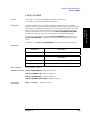
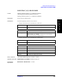
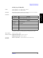
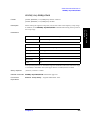
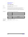
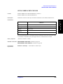
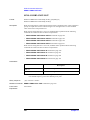
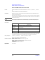
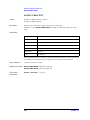
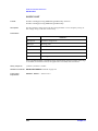
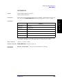
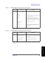
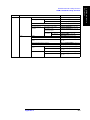
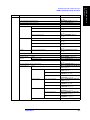
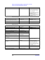
Parameters for Complex Trace
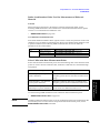
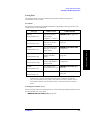
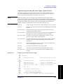
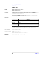
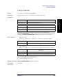
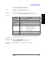
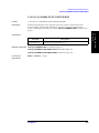
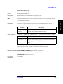
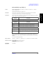
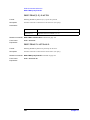
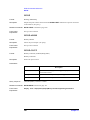
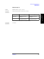
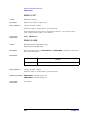
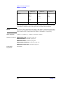
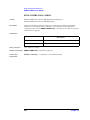
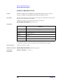
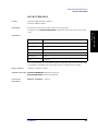
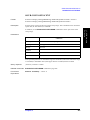
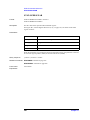
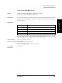
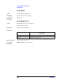
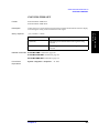
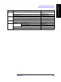
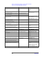
Measurement parameters
Table 3-2 shows measurement parameters available for a complex trace. Use the following
GPIB command to specify a trace number (4 or 5) and select measurement parameters.
Note that up to two measurement parameters can be displayed at any one time.
CALC{1-5}:FORM on page 298
•
Table 3-2
Measurement Parameters for Complex Trace
Measurement
parameter
GPIB
parameter
Description
Z
Z
Impedance
Y
Y
Admittance
Γ
RC
Reflection coefficient
μr
P
Complex permeability*1
εr
DC
Complex permittivity*2
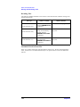
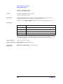
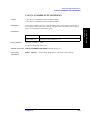
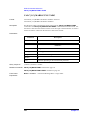
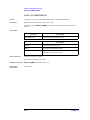
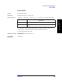
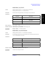
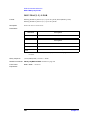
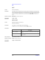
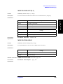
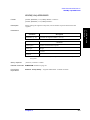
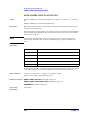
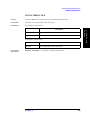
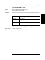
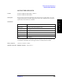
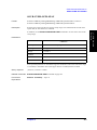
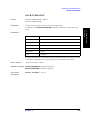
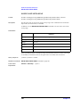
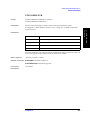
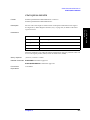
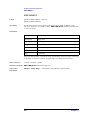
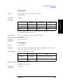
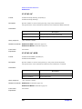
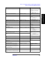
Display Format
Table 3-3 shows display formats available for a complex trace. Use the following GPIB
command to select a display format from Complex plane format, Polar format, Smith chart,
or Admittance chart.
DISP:TRAC{1-5}:GRAT:FORM on page 357
•
Table 3-3
Display Format for Complex Trace
Measurement
parameters
Display format
Z,Y,μr,εr
Complex plane or Polar format
Γ
Complex plane format, Polar format, Smith chart, or Admittance
chart
Chapter 3
43
3. Setting Measurement
Conditions
*1. Parameters selectable when the Magnetic Material measurement mode is selected.
*2. Parameters selectable when the Dielectric Material measurement mode is selected.
Setting Measurement Conditions
Set Sweep Conditions
Set Sweep Conditions
The following section explains how to set the sweep conditions. The sweep condition is a
common parameter to all of traces.
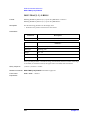
Select Sweep Parameter
The user must select a desired combination of a sweep parameter and a sweep type.
E4991A provides the following combinations of four sweep parameters and three sweep
types.
•
Frequency sweep (Linear sweep)
•
Frequency sweep (Log sweep)
•
Frequency sweep (Segment sweep)
•
Oscillator level sweep (Linear sweep)
•
dc bias voltage sweep*1 (Linear sweep)
•
dc bias current sweep*1 (Linear sweep)
Use the following GPIB command to select both sweep parameter and sweep type.
•
NOTE
SWE:TYPE on page 515
Segment conditions must be set in the segment sweep table before the sweep type is set to
Segment sweep. For details on how to create the segment sweep table, see “Combination of
Several Sweep Conditions (Segment Sweep)” on page 64.
Set Number of Measurement Points
Use the following GPIB command to set the number of measurement points for one sweep.
•
SWE:POIN on page 511
Set Sweep Direction
Use the following GPIB command to set the sweep direction to UP or DOWN.
•
SWE:DIR on page 508
*1. Selectable when the E4991A has option 001 (dc bias function) installed.
44
Chapter 3
Setting Measurement Conditions
Set Sweep Conditions
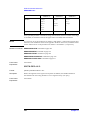
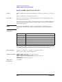
Set Sweep Range
Sweep range can be set in two ways: by specifying the center value and span value of the
sweep range or by specifying the sweep start value and sweep stop value. Use the
following GPIB commands to set a sweep range.
NOTE
When sweep start or stop values are changed, center and span values are also changed
accordingly.
The E4991A provides a GPIB command to specify the sweep range for each sweep
parameter.
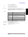
Frequency Sweep (Linear/Log Sweep)
If frequency sweep is selected as the sweep parameter, use the following GPIB commands
to set a sweep range.
Sweep parameter
Frequency sweep
Sweep range
GPIB command
FREQ:STAR on page 378
Stop value
FREQ:STOP on page 379
Center value
FREQ:CENT on page 376
Span value
FREQ:SPAN on page 377
Full span value
FREQ:SPAN:FULL on page 377
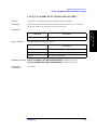
Oscillator Level Sweep
When oscillator level sweep is selected as the sweep parameter, note that the GPIB
command used to set the sweep range depends on the unit in which an oscillator level is set
(current/voltage/dBm). From the following table, select the appropriate GPIB commands
to set the sweep range and to set the oscillator level mode to sweep mode.
Sweep parameter
Oscillator level sweep Set in current
Set in voltage
Set in dBm
Chapter 3
Mode/sweep range
GPIB command
Mode
SOUR:CURR:MODE on page 460
Start value
SOUR:CURR:STAR on page 468
Stop value
SOUR:CURR:STOP on page 469
Center value
SOUR:CURR:CENT on page 458
Span value
SOUR:CURR:SPAN on page 467
Mode
SOUR:VOLT:MODE on page 479
Start value
SOUR:VOLT:STAR on page 487
Stop value
SOUR:VOLT:STOP on page 488
Center value
SOUR:VOLT:CENT on page 477
Span value
SOUR:VOLT:SPAN on page 486
Mode
SOUR:POW:MODE on page 472
Start value
SOUR:POW:STAR on page 474
Stop value
SOUR:POW:STOP on page 475
Center value
SOUR:POW:CENT on page 471
Span value
SOUR:POW:SPAN on page 473
45
3. Setting Measurement
Conditions
Start value
Setting Measurement Conditions
Set Sweep Conditions
DC Bias Voltage Sweep
If dc bias voltage sweep is selected as the sweep parameter, use one of the following GPIB
commands to set the sweep range.
Sweep parameter
dc bias voltage sweep
Sweep range
GPIB command
Start value
SOUR:VOLT:OFFS:STAR on page 483
Stop value
SOUR:VOLT:OFFS:STOP on page 485
Center value
SOUR:VOLT:OFFS:CENT on page 481
Span value
SOUR:VOLT:OFFS:SPAN on page 482
After setting up a sweep range, use the following GPIB command to set the dc bias current
limit maximum value.
SOUR:CURR:LIM:OFFS on page 459
•
Use the following GPIB command to turn on or off the dc bias output. When the dc bias
output is turned on from off, the sweep mode is automatically set to hold mode.
SOUR:VOLT:OFFS:STAT on page 484
•
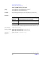
DC Bias Current Sweep
If dc bias current sweep is selected as a sweep parameter, use one of the following GPIB
commands to set the sweep range.
Sweep parameter
dc bias current sweep
Sweep range
GPIB command
Start value
SOUR:CURR:OFFS:STAR on page 464
Stop value
SOUR:CURR:OFFS:STOP on page 466
Center value
SOUR:CURR:OFFS:CENT on page 462
Span value
SOUR:CURR:OFFS:SPAN on page 463
After setting the sweep range, use the following GPIB command to set the maximum value
of the dc bias voltage limit.
•
SOUR:VOLT:LIM:OFFS on page 478
Use the following GPIB command to turn on or off the dc bias output. When the dc bias
output is turned on from off, the sweep mode is automatically set to hold mode.
•
46
SOUR:CURR:OFFS:STAT on page 465
Chapter 3
Setting Measurement Conditions
Set Sweep Conditions
Set Sweep Time
Use the following GPIB command to select whether the sweep time is set to automatic
setting or manual setting. If automatic setting is selected, this sets the shortest sweep time
from among all of the E4991A pre-defined sweep times.
•
SWE:TIME:AUTO on page 514
If manual setting is selected, use the following GPIB command to perform sweep within
the specified sweep time.
•
SWE:TIME on page 513
Set Delay Time
The delay time can be set at the sweep start or at each measurement point, if necessary.
Set Sweep Delay Time at Sweep Start
The following GPIB command can be used to delay the sweep start by the specified time.
Note that when the sweep time is set to automatic setting, the delay time at the sweep start
is set to 0 second.
SWE:DWEL1 on page 508
Set Delay Time at Each Measurement Point
The following GPIB command can be used to delay the measurement at each measurement
point by the specified time. Note that when the sweep time is set to automatic setting, the
delay time at each measurement point is set to 0 second.
•
SWE:DWEL2 on page 509
Set Delay Time at Each Segment (only segment sweep)
The following GPIB command can be used to delay the sweep start for each segment by
the specified time. Note that when the sweep time is set to automatic setting, the delay time
at each segment is set to 0 second.
•
SWE:DWEL3 on page 510
Set Frequency Span (only segment sweep)
The following GPIB command can be used to select whether a frequency span during
segment sweep is displayed for each segment or the minimum and maximum frequencies
are selected from all segments. The new span between the minimum and maximum
frequencies is displayed as a frequency span during segment sweep.
•
DISP:TRAC{1-5}:X:SPAC on page 363
Chapter 3
47
3. Setting Measurement
Conditions
•
Setting Measurement Conditions
Set Measurement Source
Set Measurement Source
The following section explains how to set a measurement source. The measurement source
is a parameter common to all of the traces.
Set Source
Set CW Frequency
If the sweep parameter is set to oscillator level sweep, dc bias voltage sweep, or dc bias
current sweep, use the following GPIB command to set the CW frequency.
FREQ on page 375
•
Set Oscillator Level
If the sweep parameter is set to frequency sweep, dc bias voltage sweep, or dc bias current
sweep, note that the GPIB command used to set the oscillator level depends on the unit in
which the oscillator level is set (current/voltage/power). Select the appropriate GPIB
commands to set the oscillator mode to fixed mode and to set an output level value.
Oscillator level
Set in voltage
Set in current
Set in power (dBm)
48
Parameter to be set
GPIB command
Mode
SOUR:VOLT:MODE on page 479
Output level value
SOUR:VOLT on page 476
Mode
SOUR:CURR:MODE on page 460
Output level value
SOUR:CURR on page 457
Mode
SOUR:POW:MODE on page 472
Output level value
SOUR:POW on page 470
Chapter 3
Setting Measurement Conditions
Set Measurement Source
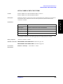
Set DC Bias (DC Bias Function)
If the sweep parameter is set to frequency sweep or oscillator level sweep, the following
GPIB command can be used to apply the dc bias to the DUT in either fixed voltage or
current source mode.
Set in Fixed Voltage Source Mode
Output mode
Fixed voltage source
Parameter to be set
Output voltage level
GPIB command
SOUR:VOLT:OFFS on page 480
Current limit maximum value SOUR:CURR:LIM:OFFS on page 459
Use the following GPIB command to turn on or off the dc bias output. Note that when the
dc bias is turned on from off, the sweep mode is automatically set to hold mode.
•
SOUR:VOLT:OFFS:STAT on page 484
Set in Fixed Current Source Mode
Output mode
Fixed current source
Parameter to be set
Output current level
GPIB command
SOUR:CURR:OFFS on page 461
Voltage limit maximum value SOUR:VOLT:LIM:OFFS on page 478
•
SOUR:CURR:OFFS:STAT on page 465
DC Bias Monitor Function
The following GPIB command can be used to display a dc bias monitor value.
•
NOTE
CALC:BMON on page 291
The dc bias monitor value displayed on the screen is that of the stimulus at an active
marker position. Therefore, the marker must be turned on and the marker must be set to the
specified stimulus value before the dc bias monitor function can be used.
Chapter 3
49
3. Setting Measurement
Conditions
Use the following GPIB command to turn on or off the dc bias output. Note that when the
dc bias is turned on from off, the sweep mode is automatically set to hold mode.
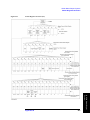
Setting Measurement Conditions
Set Averaging
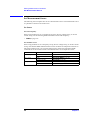
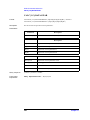
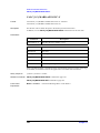
Set Averaging
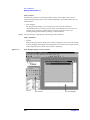
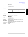
The E4991A has two types of averaging functions: sweep averaging and point averaging
(Figure 3-1).
Sweep Averaging
Use the following GPIB command to turn sweep averaging on or off.
•
CALC:AVER on page 289
After enabling sweep averaging, use the following GPIB command to set the averaging
factor.
•
CALC:AVER:COUN on page 290
The following GPIB command can be used to restart the sweep.
•
CALC:AVER:CLE on page 289
Point Averaging
Use the following GPIB command to turn point averaging on or off.
•
AVER on page 287
After enabling point averaging, use the following GPIB command to set the averaging
factor.
•
Figure 3-1
AVER:COUN on page 288
Sweep Averaging and Point Averaging
50
Chapter 3
Setting Measurement Conditions
Set Display Scale
Set Display Scale
When the measurement screen is set to display a graph, the display scale for the specified
trace can be set automatically to the most appropriate value or can be set manually to a
desired value.
Select Trace for Which Scale Is Set
If both data and memory traces are displayed on the screen, use the following GPIB
command to select the trace (data trace, memory trace, or both traces) for which the scale is
to be set.
•
DISP:TRAC{1-5}:Y:FOR on page 366
Automatic Scale Adjustment
When a trace goes out of the scale range, use the following GPIB command to adjust the
scale automatically so that the trace stays within the scale range.
DISP:TRAC{1-5}:Y:AUTO on page 364
•
DISP:TRAC:Y:AUTO:ALL on page 364
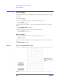
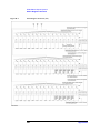
Manual Setting of Scale
In addition to automatic scale adjustment, the E4991A provides a way to manually set the
scale values. As shown in Figure 3-2, scale parameters depend on the display format of a
trace.
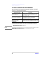
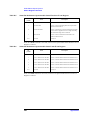
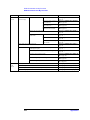
Linear Y-Axis Format
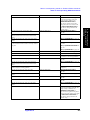
The display scale can be set in two ways: by using full-scale and reference values or by
using maximum and minimum values. Use the following GPIB commands to set the scale
parameters.
Display format
Parameter to be set
GPIB command
Linear Y-axis format
(Using max and min
values)
Maximum value
DISP:TRAC{1-3}:Y:TOP on page 372
Minimum value
DISP:TRAC{1-3}:Y:BOTT on page 365
Reference line’s position
DISP:TRAC{1-3}:Y:RPOS on page 370
Linear Y-axis format
(Using full-scale)
Full-scale value
DISP:TRAC{1-5}:Y:FULL on page 367
Reference line’s value
DISP:TRAC{1-5}:Y:RLEV on page 369
Reference line’s position
DISP:TRAC{1-3}:Y:RPOS on page 370
Chapter 3
51
3. Setting Measurement
Conditions
•
Setting Measurement Conditions
Set Display Scale
Log Y-Axis Format
Use the following GPIB commands to set the maximum and minimum values of the scale.
Display format
Log Y-axis format
Parameter to be set
GPIB command
Maximum value
DISP:TRAC{1-3}:Y:TOP on page 372
Minimum value
DISP:TRAC{1-3}:Y:BOTT on page 365
Polar Format
Use the following GPIB command to set the scale value of the outermost circle.
DISP:TRAC{1-5}:Y:FULL on page 367
•
Complex Plane Format
Use the following GPIB commands to set the X-axis and Y- axis reference values and a
full-scale value.
Display format
Complex plane format
Parameter to be set
GPIB command
X-axis reference value
DISP:TRAC{4-5}:X:RLEV on page 362
Y-axis reference value
DISP:TRAC{1-5}:Y:RLEV on page 369
Full-scale value
DISP:TRAC{1-5}:Y:FULL on page 367
Smith Chart and Admittance Chart
The scales of these formats are fixed and thus cannot be changed.
52
Chapter 3
Setting Measurement Conditions
Set Display Scale
Figure 3-2
Display Scale Parameters
3. Setting Measurement
Conditions
Use the following GPIB commands to set the scale parameters shown in Figure 3-2.
Full Scale
DISP:TRAC{1-5}:Y:FULL on page 367
Full Scale/10*1
DISP:TRAC{1-5}:Y:PDIV on page 368
Top
DISP:TRAC{1-3}:Y:TOP on page 372
Bottom
DISP:TRAC{1-3}:Y:BOTT on page 365
Ref Pos
DISP:TRAC{1-3}:Y:RPOS on page 370
Ref Val
DISP:TRAC{1-5}:Y:RLEV on page 369
Ref X
DISP:TRAC{4-5}:X:RLEV on page 362
Ref Y
DISP:TRAC{1-5}:Y:RLEV on page 369
*1. With the display format set to Linear display or Complex plane, one-tenth of the full-scale
value can be used instead. However, one-tenth of the full-scale does not always correspond
to a grid width (Grid lines are not always displayed at an interval of one-tenth of the
full-scale).
Chapter 3
53
Setting Measurement Conditions
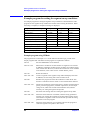
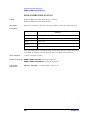
Example program for setting the measuring conditions
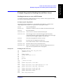
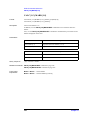
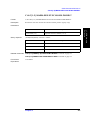
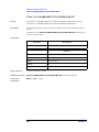
Example program for setting the measuring conditions
An example program for setting the measuring conditions is shown below. This program
sets the E4991A as follows after resetting it. When the setting is complete, a completion
message is displayed.
Setting item
Trace 1
Trace 2
Trace 4
Measurement mode
Impedance measurement
Display trace
Scalar
Scalar
Complex
Measurement parameter
|Z|
θz
Γ
Display format
Log Y-axis
Linear Y-axis
Smith
Phase display unit
---
° (degrees)
---
Expanded phase display
---
On
---
Sweep parameter (sweep type)
Frequency sweep (log sweep)
Start frequency
100 MHz
Stop frequency
3 GHz
Number of measurement points
201
Measurement direction
Up
Sweep averaging factor
16
Point averaging factor
0 (off)
Sweep time
Auto
Delay time at the start of sweep
0 seconds
Delay time at each measurement
point
0 seconds (When the sweep time is auto, the delay time
is 0 seconds)
Oscillator level
1 mA
dc bias output voltage level
15 V
dc bias current limit maximum value
10 mA
Full-scale value
---
500
---
Reference value
---
0
---
Reference position
---
50
---
Maximum scale
100
---
---
Minimum scale
0.1
---
---
54
Chapter 3
Setting Measurement Conditions
Example program for setting the measuring conditions
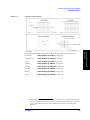
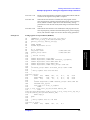
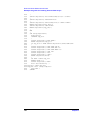
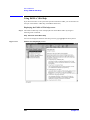
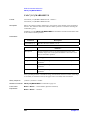
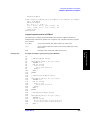
Example program using HTBasic
The program shown in Example 3-1 is saved under the filename setup.htb on the sample
programs disk. The details of this program are explained as follows.
Sets the GPIB address of the E4991A.
Lines 250 - 290
Substitutes a variable for the trace number.
Lines 310 - 450
Substitutes variables for the on/off status of each trace display,
measurement parameter, trace display format, and Y-axis display
format. In addition, when the measurement parameter is a phase (Trace
2), substitutes variables for the expanded phase display and the phase
display format display unit.
Lines 470 - 510
Substitutes variables for the sweep-related parameter values (sweep
parameter/type, sweep range, number of measurement points, and
sweep direction).
Lines 520 - 540
Substitutes variables for the average-related parameter values (sweep
averaging and point averaging).
Lines 550 - 560
Substitutes variables for the auto/manual setting of the sweep time and
sweep delay time.
Lines 570 - 580
Substitutes variables for the oscillator level-related parameters.
Lines 590 - 600
Substitutes variables for the dc bias-related parameter values.
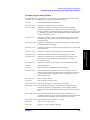
Lines 620 - 670
Substitutes variables for the on/off status of the list display of the
measurement screen and the object of the display trace (data
trace/memory trace).
Lines 680 - 720
Substitutes variables for the display scale-related parameter values.
Line 740
Resets the E4991A.
Line 780
Sets the E4991A to impedance measurement mode.
Lines 800 - 940
Sets the measurement parameters for Traces 1, 2, and 4, the trace
display format, and the Y-axis display format. In addition, for Trace 2,
sets the expanded phase display as well as the display units of the
phase display format.
Lines 960 - 970
Turns off Traces 3 and 5.
Line 1010
Sets the sweep parameter (type).
3. Setting Measurement
Conditions
Line 230
Lines 1030 - 1040 Sets the sweep range for the frequency sweep range.
Lines 1060 - 1120 Sets the measurement point, sweep direction, Sweep averaging
function on/off status, averaging factor, point averaging function
on/off status, auto/manual setting of the sweep time, and sweep delay
time.
Lines 1060 - 1120 Selects the fixed mode for oscillator current mode and sets the
oscillator current level. Next, sets the voltage level in the dc bias fixed
mode and sets the maximum value of the dc bias current limit.
Lines 1230 - 1390 Sets the display scales of Traces 1, 2, and 4.
Line 1430
Turns on the dc bias output.
Line 1470
Displays a setting completion message.
Chapter 3
55
Setting Measurement Conditions
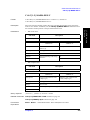
Example program for setting the measuring conditions
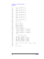
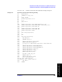
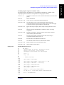
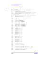
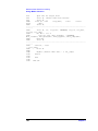
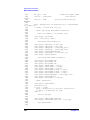
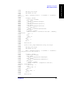
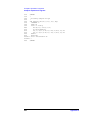
Example 3-1
Setting measuring conditions (HTBasic)
10
INTEGER Trc1,Trc2,Trc3,Trc4,Trc5
20
INTEGER Nop,Sweep_avg_coun
30
REAL Start_freq,Stop_freq,Sweep_delay
40
REAL Sour_curr,Dc_bias_v,Dc_bias_i_lim
50
REAL Full_sacle1,Full_scale2,Full_scale4
60
REAL Ref_val1,Ref_val2,Ref_val4
70
REAL Ref_pos1,Ref_pos2,Ref_pos4
80
REAL Top_scale1,Top_scale2,Top_scale4
90
REAL Bottom_scale1,Bottom_scale2,Bottom_scale4
100
DIM Trac1$[3],Trac2$[3],Trac3$[3],Trac4$[3],Trac5$[3]
110
DIM M_para1$[4],M_para2$[4],M_para4$[4]
120
DIM Disp_form1$[10],Disp_form2$[10],Disp_form4$[10]
130
DIM Disp_y_spac1$[11],Disp_y_spac2$[11],Disp_y_spac4$[11]
140
DIM Phase_unit1$[3],Phase_unit2$[3],Phase_unit4$[3]
150
DIM Phase_exp1$[3],Phase_exp2$[3],Phase_exp4$[3]
160
DIM
Sweep_type$[11],Sweep_dir$[4],Sweep_avg$[3],Point_avg$[3]
170
DIM Sweep_t_auto$[3],Sour_curr_mode$[5]
180
DIM List_page1$[3],List_page2$[3],List_page4$[3]
190
DIM Disp_trac1$[4],Disp_trac2$[4],Disp_trac4$[4]
200
DIM Buff$[9]
210
!
220
CLEAR SCREEN
230
ASSIGN @Agte4991a TO 717
240
!
250
Trc1=1
260
Trc2=2
270
Trc3=3
280
Trc4=4
290
Trc5=5
300
!
310
Trac1$="ON"
320
Trac2$="ON"
330
Trac3$="OFF"
340
Trac4$="ON"
350
Trac5$="OFF"
360
M_para1$="Z"
370
M_para2$="ZPH"
380
M_para4$="RC"
390
Disp_form1$="RECT"
400
Disp_form2$="RECT"
410
Disp_form4$="SMIT"
420
Disp_y_spac1$="LOG"
430
Disp_y_spac2$="LIN"
440
Phase_unit2$="DEG"
450
Phase_exp2$="ON"
460
!
470
Sweep_type$="LOG"
480
Start_freq=1.00E+8
490
Stop_freq=3.E+9
500
Nop=201
510
Sweep_dir$="UP"
520
Sweep_avg_coun=16
530
Sweep_avg$="ON"
540
Point_avg$="OFF"
56
Chapter 3
Setting Measurement Conditions
Example program for setting the measuring conditions
Chapter 3
3. Setting Measurement
Conditions
550
Sweep_t_auto$="ON"
560
Sweep_delay=0
570
Sour_curr_mode$="FIX"
580
Sour_curr=1.E-3
590
Dc_bias_v=15
600
Dc_bias_i_lim=1.0E-2
610
!
620
List_page1$="OFF"
630
List_page2$="OFF"
640
List_page4$="OFF"
650
Disp_trac1$="DATA"
660
Disp_trac2$="DATA"
670
Disp_trac4$="DATA"
680
Top_scale1=100
690
Bottom_scale1=.1
700
Full_scale2=500
710
Ref_val2=0
720
Ref_pos2=50
730
!
740
OUTPUT @Agte4991a;"SYST:PRES"
750
!
760
! Measurement Mode & Parameter & Disp Format Setting
770
!
780
OUTPUT @Agte4991a;"MODE IMP"
790
!
800
OUTPUT @Agte4991a;"DISP:TRAC"&VAL$(Trc1)&" "&Trac1$
810
OUTPUT @Agte4991a;"CALC"&VAL$(Trc1)&":FORM "&M_para1$
820
OUTPUT @Agte4991a;"DISP:TRAC"&VAL$(Trc1)&":GRAT:FORM
"&Disp_form1$
830
OUTPUT @Agte4991a;"DISP:TRAC"&VAL$(Trc1)&":Y:SPAC
"&Disp_y_spac1$
840
!
850
OUTPUT @Agte4991a;"DISP:TRAC"&VAL$(Trc2)&" "&Trac2$
860
OUTPUT @Agte4991a;"CALC"&VAL$(Trc2)&":FORM "&M_para2$
870
OUTPUT @Agte4991a;"DISP:TRAC"&VAL$(Trc2)&":GRAT:FORM
"&Disp_form2$
880
OUTPUT @Agte4991a;"DISP:TRAC"&VAL$(Trc2)&":Y:SPAC
"&Disp_y_spac2$
890
OUTPUT @Agte4991a;"CALC"&VAL$(Trc2)&":FORM:UNIT:ANGL
"&Phase_unit2$
900
OUTPUT @Agte4991a;"CALC"&VAL$(Trc2)&":FORM:PAR:EPH
"&Phase_exp2$
910
!
920
OUTPUT @Agte4991a;"DISP:TRAC"&VAL$(Trc4)&" "&Trac4$
930
OUTPUT @Agte4991a;"CALC"&VAL$(Trc4)&":FORM "&M_para4$
940
OUTPUT @Agte4991a;"DISP:TRAC"&VAL$(Trc4)&":GRAT:FORM
"&Disp_form4$
950
!
960
OUTPUT @Agte4991a;"DISP:TRAC"&VAL$(Trc3)&" "&Trac3$
970
OUTPUT @Agte4991a;"DISP:TRAC"&VAL$(Trc5)&" "&Trac5$
980
!
990
! Sweep & Average Setting
1000
!
1010
OUTPUT @Agte4991a;"SWE:TYPE "&Sweep_type$
1020
!
1030
OUTPUT @Agte4991a;"FREQ:STAR "&VAL$(Start_freq)
1040
OUTPUT @Agte4991a;"FREQ:STOP "&VAL$(Stop_freq)
1050
!
57
Setting Measurement Conditions
Example program for setting the measuring conditions
1060
OUTPUT @Agte4991a;"SWE:POIN "&VAL$(Nop)
1070
OUTPUT @Agte4991a;"SWE:DIR "&Sweep_dir$
1080
OUTPUT @Agte4991a;"CALC:AVER:COUN "&VAL$(Sweep_avg_coun)
1090
OUTPUT @Agte4991a;"CALC:AVER "&Sweep_avg$
1100
OUTPUT @Agte4991a;"AVER "&Point_avg$
1110
OUTPUT @Agte4991a;"SWE:TIME:AUTO "&Sweep_t_auto$
1120
OUTPUT @Agte4991a;"SWE:DWEL1 "&VAL$(Sweep_delay)
1130
!
1140
! Source Setting
1150
!
1160
OUTPUT @Agte4991a;"SOUR:CURR:MODE "&Sour_curr_mode$
1170
OUTPUT @Agte4991a;"SOUR:CURR "&VAL$(Sour_curr)
1180
OUTPUT @Agte4991a;"SOUR:VOLT:OFFS "&VAL$(Dc_bias_v)
1190
OUTPUT @Agte4991a;"SOUR:CURR:LIM:OFFS "&VAL$(Dc_bias_i_lim)
1200
!
1210
! Trace1 Setting
1220
!
1230
OUTPUT @Agte4991a;"DISP:TRAC"&VAL$(Trc1)&":TEXT
"&List_page1$
1240
OUTPUT @Agte4991a;"CALC"&VAL$(Trc1)&":MATH:FUNC
"&Disp_trac1$
1250
OUTPUT @Agte4991a;"DISP:TRAC"&VAL$(Trc1)&":Y:TOP
"&VAL$(Top_scale1)
1260
OUTPUT @Agte4991a;"DISP:TRAC"&VAL$(Trc1)&":Y:BOTT
"&VAL$(Bottom_scale1)
1270
!
1280
! Trace2 Setting
1290
!
1300
OUTPUT @Agte4991a;"DISP:TRAC"&VAL$(Trc2)&":TEXT
"&List_page2$
1310
OUTPUT @Agte4991a;"CALC"&VAL$(Trc2)&":MATH:FUNC
"&Disp_trac2$
1320
OUTPUT @Agte4991a;"DISP:TRAC"&VAL$(Trc2)&":Y:FULL
"&VAL$(Full_scale2)
1330
OUTPUT @Agte4991a;"DISP:TRAC"&VAL$(Trc2)&":Y:RLEV
"&VAL$(Ref_val2)
1340
OUTPUT @Agte4991a;"DISP:TRAC"&VAL$(Trc2)&":Y:RPOS
"&VAL$(Ref_pos2)
1350
!
1360
! Trace4 Setting
1370
!
1380
OUTPUT @Agte4991a;"DISP:TRAC"&VAL$(Trc4)&":TEXT
"&List_page4$
1390
OUTPUT @Agte4991a;"CALC"&VAL$(Trc4)&":MATH:FUNC
"&Disp_trac4$
1400
!
1410
! DC Bias ON
1420
!
1430
OUTPUT @Agte4991a;"SOUR:VOLT:OFFS:STAT ON"
1440
!
1450
OUTPUT @Agte4991a;"*OPC?"
1460
ENTER @Agte4991a;Buff$
1470
PRINT "Measurement Condition Setup Complete"
1480
!
1490
END
58
Chapter 3
Setting Measurement Conditions
Example program for setting the measuring conditions
Example program using macro (E4991A VBA)
The program shown in Example 3-2 is saved under the filename setup.bas on the sample
programs disk. The details of this program are explained as follows.
Substitutes a variable for the trace number.
Lines 320 - 460
Substitutes variables for the on/off status of each trace display,
measurement parameter, trace display format, and Y-axis display
format. In addition, when the measurement parameter is a phase (Trace
2), substitutes variables for the expanded phase display and the phase
display format display unit.
Lines 480 - 520
Substitutes variables for the sweep-related parameter values (sweep
parameter/type, sweep range, number of measurement points, and
sweep direction).
Lines 530 - 550
Substitutes variables for the average-related parameter values (sweep
averaging and point averaging).
Lines 560 - 570
Substitutes variables for the auto/manual setting of the sweep time and
sweep delay time.
Lines 580 - 590
Substitutes variables for the oscillator level-related parameters.
Lines 600 - 610
Substitutes variables for the dc bias-related parameter values.
Lines 630 - 680
Substitutes variables for the on/off status of the list display of the
measurement screen and the object of the display trace (data
trace/memory trace).
Lines 690 - 730
Substitutes variables for the display scale-related parameter values.
Line 750
Resets the E4991A.
Line 790
Sets the E4991A to the impedance measurement mode.
Lines 810 - 950
Sets the measurement parameters for Traces 1, 2, and 4, the trace
display format, and the Y-axis display format. In addition, for Trace 2,
sets the expanded phase display, as well as the display units of the
phase display format.
Lines 970 - 980
Turns off the Traces 3 and 5.
Line 1020
Sets the sweep parameter (type).
3. Setting Measurement
Conditions
Lines 260 - 300
Lines 1040 - 1050 Sets the sweep range for the frequency sweep range.
Lines 1070 - 1130 Sets the measurement point, sweep direction, Sweep averaging
function on/off status, averaging factor, point averaging function
on/off status, auto/manual setting of the sweep time, and sweep delay
time.
Lines 1170 - 1200 Selects the fixed mode of oscillator current mode and sets the
oscillator current level. Next, sets the voltage level in the dc bias fixed
mode and sets the maximum value of the dc bias current limit.
Lines 1240 - 1410 Sets the display scales of Traces 1, 2, and 4.
Line 1450
Turns on the dc bias output.
Line 1510
Stops the execution of the macro.
Chapter 3
59
Setting Measurement Conditions
Example program for setting the measuring conditions
Example 3-2
Setting measuring conditions (macro)
10
Sub Main()
20
Dim trc1 As Integer, trc2 As Integer, trc3 As Integer
30
Dim trc4 As Integer, trc5 As Integer
40
Dim nop As Integer, sweep_avg_coun As Integer
50
Dim start_freq As Double, stop_freq As Double, sweep_delay
As Double
60
Dim sour_curr As Double, dc_bias_v As Double,
dc_bias_i_lim As Double
70
Dim full_scale1 As Double, full_scale2 As Double,
full_scale4 As Double
80
Dim ref_val1 As Double, ref_val2 As Double, ref_val4 As
Double
90
Dim ref_pos1 As Double, ref_pos2 As Double, ref_pos4 As
Double
100
Dim top_scale1 As Double, top_scale2 As Double, top_scale4
As Double
110
Dim bottom_scale1 As Double, bottom_scale2 As Double,
bottom_scale4 As Double
120
Dim trac1 As String, trac2 As String, trac3 As String
130
Dim trac4 As String, trac5 As String
140
Dim m_para1 As String, m_para2 As String, m_para4 As
String
150
Dim disp_form1 As String, disp_form2 As String, disp_form4
As String
160
Dim disp_y_spac1 As String, disp_y_spac2 As String,
disp_y_spac4 As String
170
Dim phase_unit1 As String, phase_unit2 As String,
phase_unit4 As String
180
Dim phase_exp1 As String, phase_exp2 As String, phase_exp4
As String
190
Dim sweep_type As String, sweep_dir As String
200
Dim sweep_avg As String, point_avg As String
210
Dim sweep_t_auto As String, sour_curr_mode As String
220
Dim list_page1 As String, list_page2 As String, list_page4
As String
230
Dim disp_trac1 As String, disp_trac2 As String, disp_trac4
As String
240
Dim buff As String
250
260
trc1 = 1
270
trc2 = 2
280
trc3 = 3
290
trc4 = 4
300
trc5 = 5
310
320
trac1 = "ON"
330
trac2 = "ON"
340
trac3 = "OFF"
350
trac4 = "ON"
360
trac5 = "OFF"
370
m_para1 = "Z"
380
m_para2 = "ZPH"
390
m_para4 = "RC"
400
disp_form1 = "RECT"
410
disp_form2 = "RECT"
60
Chapter 3
Setting Measurement Conditions
Example program for setting the measuring conditions
Chapter 3
3. Setting Measurement
Conditions
420
disp_form4 = "SMIT"
430
disp_y_spac1 = "LOG"
440
disp_y_spac2 = "LIN"
450
phase_unit2 = "DEG"
460
phase_exp2 = "ON"
470
480
sweep_type = "LOG"
490
start_freq = 100000000#
500
stop_freq = 3000000000#
510
nop = 201
520
sweep_dir = "UP"
530
sweep_avg_coun = 16
540
sweep_avg = "ON"
550
point_avg = "ON"
560
sweep_t_auto = "ON"
570
sweep_delay = 0
580
sour_curr_mode = "FIX"
590
sour_curr = 0.001
600
dc_bias_v = 15
610
dc_bias_i_lim = 0.01
620
630
list_page1 = "OFF"
640
list_page2 = "OFF"
650
list_page4 = "OFF"
660
disp_trac1 = "DATA"
670
disp_trac2 = "DATA"
680
disp_trac4 = "DATA"
690
top_scale1 = 100
700
bottom_scale1 = 0.1
710
full_scale2 = 500
720
ref_val2 = 0
730
ref = pos2 = 50
740
750
SCPI.Output "SYST:PRES"
760
770
' Measurement Mode & Parameter & Disp Format Setting
780
790
SCPI.Output "MODE IMP"
800
810
SCPI.Output "DISP:TRAC" & CStr(trc1) & " " & trac1
820
SCPI.Output "CALC" & CStr(trc1) & ":FORM " & m_para1
830
SCPI.Output "DISP:TRAC" & CStr(trc1) & ":GRAT:FORM " &
disp_form1
840
SCPI.Output "DISP:TRAC" & CStr(trc1) & ":Y:SPAC " &
disp_y_spac1
850
860
SCPI.Output "DISP:TRAC" & CStr(trc2) & " " & trac2
870
SCPI.Output "CALC" & CStr(trc2) & ":FORM " & m_para2
880
SCPI.Output "DISP:TRAC" & CStr(trc2) & ":GRAT:FORM " &
disp_form2
890
SCPI.Output "DISP:TRAC" & CStr(trc2) & ":Y:SPAC " &
disp_y_spac2
900
SCPI.Output "CALC" & CStr(trc2) & ":FORM:UNIT:ANGL " &
phase_unit2
910
SCPI.Output "CALC" & CStr(trc2) & ":FORM:PAR:EPH " &
phase_exp2
920
930
SCPI.Output "DISP:TRAC" & CStr(trc4) & " " & trac4
61
Setting Measurement Conditions
Example program for setting the measuring conditions
940
SCPI.Output "CALC" & CStr(trc4) & ":FORM " & m_para4
950
SCPI.Output "DISP:TRAC" & CStr(trc4) & ":GRAT:FORM " &
disp_form4
960
970
SCPI.Output "DISP:TRAC" & CStr(trc3) & " " & trac3
980
SCPI.Output "DISP:TRAC" & CStr(trc5) & " " & trac5
990
1000
' Sweep & Average Setting
1010
1020
SCPI.Output "SWE:TYPE " & sweep_type
1030
1040
SCPI.Output "FREQ:STAR " & CStr(start_freq)
1050
SCPI.Output "FREQ:STOP " & CStr(stop_freq)
1060
1070
SCPI.Output "SWE:POIN " & CStr(nop)
1080
SCPI.Output "SWE:DIR " & sweep_dir
1090
SCPI.Output "CALC:AVER:COUN " & CStr(sweep_avg_coun)
1100
SCPI.Output "CALC:AVER " & sweep_avg
1110
SCPI.Output "AVER " & point_avg
1120
SCPI.Output "SWE:TIME:AUTO " & sweep_t_auto
1130
SCPI.Output "SWE:DWEL1 " & CStr(sweep_delay)
1140
1150
' Source Setting
1160
1170
SCPI.Output "SOUR:CURR:MODE " & sour_curr_mode
1180
SCPI.Output "SOUR:CURR " & CStr(sour_curr)
1190
SCPI.Output "SOUR:VOLT:OFFS " & CStr(dc_bias_v)
1200
SCPI.Output "SOUR:CURR:LIM:OFFS " & CStr(dc_bias_i_lim)
1210
'
1220
' Trace1 Setting
1230
'
1240
SCPI.Output "DISP:TRAC" & CStr(trc1) & ":TEXT " &
list_page1
1250
1260
SCPI.Output "CALC" & CStr(trc1) & ":MATH:FUNC " &
disp_trac1
1270
SCPI.Output "DISP:TRAC" & CStr(trc1) & ":Y:TOP " &
CStr(top_scale1)
1280
SCPI.Output "DISP:TRAC" & CStr(trc1) & ":Y:BOTT " &
CStr(bottom_scale1)
1290
1300
' Trace2 Setting
1310
1320
SCPI.Output "DISP:TRAC" & CStr(trc2) & ":TEXT " &
list_page2
1330
SCPI.Output "CALC" & CStr(trc2) & ":MATH:FUNC " &
disp_trac2
1340
SCPI.Output "DISP:TRAC" & CStr(trc2) & ":Y:FULL " &
CStr(full_scale2)
1350
SCPI.Output "DISP:TRAC" & CStr(trc2) & ":Y:RLEV " &
CStr(ref_val2)
1360
SCPI.Output "DISP:TRAC" & CStr(trc2) & ":Y:RPOS " &
CStr(ref_pos2)
1370
1380
' Trace4 Setting
1390
1400
SCPI.Output "DISP:TRAC" & CStr(trc4) & ":TEXT " &
list_page4
62
Chapter 3
Setting Measurement Conditions
Example program for setting the measuring conditions
1410
SCPI.Output "CALC" & CStr(trc4) & ":MATH:FUNC " &
disp_trac4
1420
1430
' DC Bias ON
1440
1450
SCPI.Output "SOUR:VOLT:OFFS:STAT ON"
1460
1470
buff = SCPI.Query("*OPC?")
1480
1490
MsgBox ("Measurement Condition Setup Complete")
1500
1510
End
1520
1530
End Sub
3. Setting Measurement
Conditions
Chapter 3
63
Setting Measurement Conditions
Combination of Several Sweep Conditions (Segment Sweep)
Combination of Several Sweep Conditions (Segment Sweep)
The Agilent E4991A allows you to set combinations of up to 16 segments, each with its
own sweep conditions, to perform segment sweep. A segment sweep table must be created
before segment sweep can be performed.
Create/Edit Segment Sweep Table
The segment sweep table can be created or edited in two ways: specifying each segment
parameter individually or specifying parameters collectively.
Display Segment Sweep Table
Use the following GPIB command to display the sweep conditions on the segment sweep
table.
DISP:TEXT{1-3}:SET on page 356
•
Create Segments and Read Total Number of Segments
To create a segment, use the following GPIB command to create the specified number of
segments in the segment sweep table to make them available for editing. This command
clears the existing segments and creates new segments. When this command is used in the
query format, the total number of segments contained in the table is read.
SEGM:COUN on page 397
•
Delete All Segments
Use the following GPIB command to delete all of the segments in the segment sweep table.
SEGM:DEL:ALL on page 406
•
Select Oscillator Level Unit
Use the one of the following GPIB commands to select the unit (current/voltage/power) in
which the oscillator level is set when the segment sweep table is created.
Oscillator level
GPIB command
Set in current
SEGM:CURR:STAT on page 402
Set in voltage
SEGM:VOLT:STAT on page 418
Set in power (dBm)
SEGM:POW:STAT on page 412
Select DC Bias Output Mode (DC Bias Function)
When the dc bias function is used, use one of the following GPIB commands to select
whether the dc bias output level is set to the fixed voltage or fixed current source mode
when the segment sweep table is created.
Output mode
GPIB command
Fixed current source mode
SEGM:CURR:OFFS:STAT on page 399
Fixed voltage source mode
SEGM:VOLT:OFFS:STAT on page 417
64
Chapter 3
Setting Measurement Conditions
Combination of Several Sweep Conditions (Segment Sweep)
Set Each Segment Parameter Individually
Use the following GPIB command to set each parameter in the segment sweep table.
Table 3-4
Set of Parameters in Segment Sweep Table
Parameter
Frequency sweep range
GPIB command
Start value
SEGM{1-16}:FREQ:STAR on page 409
Stop value
SEGM{1-16}:FREQ:STOP on page 410
Center value
SEGM{1-16}:FREQ:CENT on page 407
Span value
SEGM{1-16}:FREQ:SPAN on page 408
Number of measurement points
*1
SEGM{1-16}:SWE:POIN on page 413
SEGM{1-16}:AVER:COUN on page 396
Point averaging factor
Current value
SEGM{1-16}:CURR on page 398
Voltage value
SEGM{1-16}:VOLT on page 414
Power (dBm) value
SEGM{1-16}:POW on page 411
dc bias (Fixed voltage
source)
Output voltage level
SEGM{1-16}:VOLT:OFFS on page 416
Current limit
maximum value
SEGM{1-16}:CURR:LIM on page 400
dc bias (Fixed current
source)
Output current level
SEGM{1-16}:CURR:OFFS on page 401
Voltage limit
maximum value
SEGM{1-16}:VOLT:LIM on page 415
Oscillator level
3. Setting Measurement
Conditions
*1. The total number of measurement points for each segment cannot exceed 801. The
SWE:POIN command can be used to read the total number of measurement points for
each segment.
Set Segment Parameters Collectively
Use the following GPIB command to collectively set all of the parameters required to
create the segment sweep table for each segment.
•
SEGM{1-16}:DATA on page 403
The following GPIB command can be used to apply the same parameter values to all of the
segments on the segment sweep table.
•
SEGM:DATA:ALL on page 405
Turn On/Off DC Bias Output (DC Bias Function)
If dc bias is applied to the DUT during segment sweep, use the following GPIB command
to turn on or off the dc bias output. When the output is switched from off to on, sweep is
automatically set to the hold mode.
Use the following GPIB command to turn on or off the dc bias output in the fixed voltage
source mode.
•
SOUR:VOLT:OFFS:STAT on page 484
Use the following GPIB command to turn on or off the dc bias output in the fixed current
source mode.
•
SOUR:CURR:OFFS:STAT on page 465
Chapter 3
65
Setting Measurement Conditions
Example program for setting the segment sweep conditions
Example program for setting the segment sweep conditions
An example program for setting the segment sweep conditions is described below. This
program sets the segment sweep conditions as follows after resetting the E4991A. When
the setting is complete, a completion message is displayed.
Segment sweep table setting item
Segment 1
Segment 2
Segment 3
Start frequency
1 MHz
100 MHz
1 GHz
Stop frequency
100 MHz
1 GHz
3 GHz
Number of measurement points
101
101
51
Oscillator output level
100 mV
100 mV
100 mV
dc bias output voltage level
10 V
10 V
10 V
dc bias current limit maximum value
10 mA
10 mA
10 mA
Number of point averaging
32
4
4
Sweep type
Segment sweep
Delay time at each segment
0.1 sec
X-axis span display format
Each segment
Example program using HTBasic
The program shown in Example 3-3 is saved under the filename segm_set.htb on the
sample programs disk. The details of this program are explained as follows.
Line 60
Sets the GPIB address of the E4991A.
Lines 80 - 100
Substitutes a variable for the total number of segments to be created.
In addition, substitutes variables for the oscillator level and the setting
units of the dc bias. However, when the dc bias function is not installed
in the E4991A, enters “OFF” for the variable Dcbias_units$.
Line 140
Resets the E4991A.
Lines 150 - 180
Creates a segment in the segment sweep table and displays the table.
In addition, sets the setting units of the oscillator level.
Line 200
Branches the program for either the condition in which the dc bias
function is installed or that in which it is not installed in the E4991A.
Lines 250 - 270
Declares the parameters (start/stop frequency, number of measurement
points, point averaging factor, oscillator output level, dc bias output
voltage level, and dc bias current limit maximum value) that are
necessary for setting the segment sweep table.
Line 290
Sets the dc bias setting units for creating the segment sweep table.
Lines 300 - 340
When the dc bias function is installed, reads the setting parameters
necessary for creating the segment sweep table while looping for the
total number of segments in the section and then provides the setting
parameters to the sub-program.
Lines 400 - 480
When the dc bias function is not installed, calls the sub-program to
create the segment sweep table in this section.
66
Chapter 3
Setting Measurement Conditions
Example program for setting the segment sweep conditions
Example 3-3
Lines 520 - 540
Reads out the total number of segments created and indicates that the
creation of the segment sweep table is complete.
Line 600 -760
When the dc bias function is installed, this sub program sets the
start/stop frequency, number of measurement points, point averaging
factor, and the oscillator output level. Sets the necessary setting
parameters for each dc bias mode (fixed voltage source/fixed current
source).
Lines 800 - 880
When the dc bias function is not installed, this sub-program sets the
start/stop frequency, number of measurement points, point averaging
factor, and oscillator output level for non-dc bias setting parameters.
Setting segment sweep conditions (HTBasic)
Chapter 3
67
3. Setting Measurement
Conditions
10
INTEGER No_of_segment,Nop,Point_avg,Segm_no
20
REAL Start_f,Stop_f,Osc,Dcbias,Dcbias_lim
30
DIM Osc_unit$[7],Dcbias_unit$[6]
40
!
50
CLEAR SCREEN
60
ASSIGN @Agte4991a TO 717
70
!
80
No_of_segment=3
90
Osc_unit$="VOLT"
! CURR/VOLT/POW
100
Dcbias_unit$="VOLT"
! CURR/VOLT/OFF
110
!
120
! Initial Setting
130
!
140
OUTPUT @Agte4991a;"SYST:PRES"
150
OUTPUT @Agte4991a;"SEGM:COUN "&VAL$(No_of_segment)
160
OUTPUT @Agte4991a;"DISP:TEXT:STAT ON"
170
OUTPUT @Agte4991a;"DISP:TEXT1:SET"
180
OUTPUT @Agte4991a;"SEGM:"&Osc_unit$&":STAT ON"
190
!
200
IF Dcbias_unit$="CURR" OR Dcbias_unit$="VOLT" THEN
210
!
220
! Entry Segment Data with DC Bias
230
!
240 Data_w_bias:!
250
DATA
1E6, 100E6, 101, 32,
0.1,
10,
0.01
260
DATA 100E6,
1E9, 101,
4,
0.1,
10,
0.01
270
DATA
1E9,
3E9,
51,
4,
0.1,
10,
0.01
280
!
290
OUTPUT @Agte4991a;"SEGM:"&Dcbias_unit$&":OFFS:STAT ON"
300
RESTORE Data_w_bias
310
FOR Segm_no=1 TO No_of_segment
320
READ
Start_f,Stop_f,Nop,Point_avg,Osc,Dcbias,Dcbias_lim
330
CALL
Segm_tbl_bias(@Agte4991a,Segm_no,Start_f,Stop_f,Nop,Point_avg,Osc_u
nit$,Osc,Dcbias_unit$,Dcbias,Dcbias_lim)
340
NEXT Segm_no
350
ELSE
360
!
370
! Entry Segment Data w/o DC Bias
380
!
390 Data_wo_bias:!
400
DATA
1E6, 100E6, 101, 32,
0.1
Setting Measurement Conditions
Example program for setting the segment sweep conditions
410
DATA 100E6,
1E9, 101,
4,
0.1
420
DATA
1E9,
3E9,
51,
4,
0.1
430
!
440
RESTORE Data_wo_bias
450
FOR Segm_no=1 TO No_of_segment
460
READ Start_f,Stop_f,Nop,Point_avg,Osc
470
CALL
Segm_tbl(@Agte4991a,Segm_no,Start_f,Stop_f,Nop,Point_avg,Osc_unit$,
Osc)
480
NEXT Segm_no
490
END IF
500
!
510 Finish_entry:!
520
OUTPUT @Agte4991a;"SEGM:COUN?"
530
ENTER @Agte4991a;Seg_count
540
PRINT "Preparation of Segment Table finished. (No. of
Segmnet: "&VAL$(Seg_count)&")"
550
!
560
END
570
!
580
! Segment Table Setting with DC Bias
590
!
600
SUB Segm_tbl_bias(@Agte4991a,INTEGER Seg_no,REAL
Start_f,Stop_f,INTEGER Nop,Point_avg,Osc_unit$,REAL
Osc,Dcbias_unit$,REAL Dcbias,Dcbias_lim)
610
!
620
OUTPUT @Agte4991a;"SEGM"&VAL$(Seg_no)&":FREQ:STAR
"&VAL$(Start_f)
630
OUTPUT @Agte4991a;"SEGM"&VAL$(Seg_no)&":FREQ:STOP
"&VAL$(Stop_f)
640
OUTPUT @Agte4991a;"SEGM"&VAL$(Seg_no)&":SWE:POIN
"&VAL$(Nop)
650
OUTPUT @Agte4991a;"SEGM"&VAL$(Seg_no)&":AVER:COUN
"&VAL$(Point_avg)
660
OUTPUT @Agte4991a;"SEGM"&VAL$(Seg_no)&":"&Osc_unit$&"
"&VAL$(Osc)
670
SELECT Dcbias_unit$
680
CASE "VOLT"
690
OUTPUT @Agte4991a;"SEGM"&VAL$(Seg_no)&":VOLT:OFFS
"&VAL$(Dcbias)
700
OUTPUT @Agte4991a;"SEGM"&VAL$(Seg_no)&":CURR:LIM
"&VAL$(Dcbias_lim)
710
CASE "CURR"
720
OUTPUT @Agte4991a;"SEGM"&VAL$(Seg_no)&":CURR:OFFS
"&VAL$(Dcbias)
730
OUTPUT @Agte4991a;"SEGM"&VAL$(Seg_no)&":VOLT:LIM
"&VAL$(Dcbias_lim)
740
END SELECT
750
!
760
SUBEND
770
!
780
! Segment Table Setting w/o DC Bias
790
!
800
SUB Segm_tbl(@Agte4991a,INTEGER Seg_no,REAL
Start_f,Stop_f,INTEGER Nop,Point_avg,Osc_unit$,REAL Osc)
810
!
820
OUTPUT @Agte4991a;"SEGM"&VAL$(Seg_no)&":FREQ:STAR
"&VAL$(Start_f)
68
Chapter 3
Setting Measurement Conditions
Example program for setting the segment sweep conditions
830
OUTPUT
"&VAL$(Stop_f)
840
OUTPUT
"&VAL$(Nop)
850
OUTPUT
"&VAL$(Point_avg)
860
OUTPUT
"&VAL$(Osc)
870
!
880
SUBEND
@Agte4991a;"SEGM"&VAL$(Seg_no)&":FREQ:STOP
@Agte4991a;"SEGM"&VAL$(Seg_no)&":SWE:POIN
@Agte4991a;"SEGM"&VAL$(Seg_no)&":AVER:COUN
@Agte4991a;"SEGM"&VAL$(Seg_no)&":"&Osc_unit$&"
3. Setting Measurement
Conditions
Chapter 3
69
Setting Measurement Conditions
Example program for setting the segment sweep conditions
Example program using macro (E4991A VBA)
The program shown in Example 3-4 is saved under the filename segm_set.bas on the
sample programs disk. The details of this program are explained as follows.
Example 3-4
Lines 90 - 110
Substitutes a variable for the total number of segments to be created.
In addition, substitutes variables for the oscillator level and the setting
units of the dc bias. However, when the dc bias function is not installed
in the E4991A, enters “OFF” for the variable Dcbias_units$.
Lines 130 - 330
Substitutes a variable for the parameters (start/stop frequency, number
of measurement points, point averaging factor, oscillator output level,
dc bias output voltage level, and dc bias current limit maximum value)
that are necessary for setting the segment sweep table.
Line 370
Resets the E4991A.
Lines 380 - 400
Creates a segment in the segment sweep table and displays the
segment table. In addition, sets the setting units of the oscillator level.
Line 420
Branches the program for either the condition in which the dc bias
function is installed or that in which it is not installed in the E4991A.
Line 430
Sets the dc bias setting units for creating the segment sweep table.
Lines 440 - 460
When the dc bias function is installed, reads the setting parameters
necessary for creating the segment sweep table while looping for the
total number of the segments in the section and then provides the
setting parameters to the sub-program.
Lines 480 - 480
When the dc bias function is not installed, reads the setting parameters
necessary for creating the segment sweep table while looping for the
total number of the segments in section and then provides the setting
parameters to the sub-program.
Lines 530 - 550
Reads out the total number of segments created and displays a
message reading “Preparation of Segment Table Finished.”
Line 570
Stops the execution of the macro.
Line 610 -770
When the dc bias function is installed, this sub-program
(segm_tbl_bias) sets the start/stop frequency, number of measurement
points, point averaging factor, and the oscillator output level. Sets the
necessary setting parameters for each dc bias mode (fixed voltage
source/fixed current source).
Lines 790 - 870
When the dc bias function is not installed, this sub-program
(segm_tbl) sets the start/stop frequency, number of measurement
points, point averaging factor, and oscillator output level except for dc
bias setting parameters.
Setting segment sweep conditions (macro)
10
Sub Main()
20
Dim no_of_segment As Integer, segm_no As Integer
30
Dim nop(3) As Integer, point_avg(3) As Integer
40
Dim start_f(3) As Double, stop_f(3) As Double
50
Dim osc(3) As Double, dcbias(3) As Double, dcbias_lim(3)
As Double
60
Dim segm_count As Integer
70
Chapter 3
Setting Measurement Conditions
Example program for setting the segment sweep conditions
Chapter 3
3. Setting Measurement
Conditions
70
Dim osc_unit As String, dcbias_unit As String
80
90
no_of_segment = 3
100
osc_unit = "VOLT"
110
dcbias_unit = "CURR"
120
130
start_f(1) = 1000000#
140
stop_f(1) = 100000000#
150
nop(1) = 101
160
point_avg(1) = 32
170
osc(1) = 0.1
180
dcbias(1) = 10
190
dcbias_lim(1) = 0.01
200
start_f(2) = 100000000#
210
stop_f(2) = 1000000000#
220
nop(2) = 101
230
point_avg(2) = 4
240
osc(2) = 0.1
250
dcbias(2) = 10
260
dcbias_lim(2) = 0.01
270
start_f(3) = 1000000000#
280
stop_f(3) = 3000000000#
290
nop(3) = 51
300
point_avg(3) = 4
310
osc(3) = 0.1
320
dcbias(3) = 10
330
dcbias_lim(3) = 0.01
340
350
' Initial Setting
360
370
SCPI.Output "SYST:PRES"
380
SCPI.Output "SEGM:COUN " & CStr(no_of_segment)
390
SCPI.Output "DISP:TEXT:STAT ON"
400
SCPI.Output "SEGM:" & osc_unit & ":STAT ON"
410
420
If dcbias_unit = "VOLT" Or dcbias_unit = "CURR" Then
430
SCPI.Output "SEGM:" & dcbias_unit & ":OFFS:STAT ON"
440
For segm_no = 1 To no_of_segment
450
Call segm_tbl_bias(segm_no, start_f(segm_no),
stop_f(segm_no), nop(segm_no), point_avg(segm_no), osc_unit,
osc(segm_no), dcbias_unit, dcbias(segm_no), dcbias_lim(segm_no))
460
Next segm_no
470
ElseIf dcbias_unit = "OFF" Then
480
For segm_no = 1 To no_of_segment
490
Call segm_tbl(segm_no, start_f(segm_no),
stop_f(segm_no), nop(segm_no), point_avg(segm_no), osc_unit,
osc(segm_no))
500
Next segm_no
510
End If
520
530
segm_coun = SCPI.Query("SEGM:COUN?")
540
SCPI.Output "DISP:TEXT1:SET"
550
MsgBox ("Preparation of Segment Table Finished. (No. of
Segment: " & CStr(segm_coun)) & ")"
560
570
End
580
590
End Sub
71
Setting Measurement Conditions
Example program for setting the segment sweep conditions
600
610
Sub segm_tbl_bias(segm_no As Integer, start_f, stop_f As
Double, nop, point_avg As Integer, osc_unit As String, osc As
Double, dcbias_unit As String, dcbias, dcbias_lim As Double)
620
630
SCPI.Output "SEGM" & CStr(segm_no) & ":FREQ:STAR " &
CStr(start_f)
640
SCPI.Output "SEGM" & CStr(segm_no) & ":FREQ:STOP " &
CStr(stop_f)
650
SCPI.Output "SEGM" & CStr(segm_no) & ":SWE:POIN " &
CStr(nop)
660
SCPI.Output "SEGM" & CStr(segm_no) & ":AVER:COUN " &
CStr(point_avg)
670
SCPI.Output "SEGM" & CStr(segm_no) & ":" & osc_unit & " "
& CStr(osc)
680
Select Case dcbias_unit
690
Case "VOLT"
700
SCPI.Output "SEGM" & CStr(segm_no) & ":VOLT:OFFS " &
CStr(dcbias)
710
SCPI.Output "SEGM" & CStr(segm_no) & ":CURR:LIM " &
CStr(dcbias_lim)
720
Case "CURR"
730
SCPI.Output "SEGM" & CStr(segm_no) & ":CURR:OFFS " &
CStr(dcbias)
740
SCPI.Output "SEGM" & CStr(segm_no) & ":VOLT:LIM " &
CStr(dcbias_lim)
750
End Select
760
770
End Sub
780
790
Sub segm_tbl(segm_no As Integer, start_f, stop_f As Double,
nop, point_avg As Integer, osc_unit As String, osc As Double)
800
810
SCPI.Output "SEGM" & CStr(segm_no) & ":FREQ:STAR " &
CStr(start_f)
820
SCPI.Output "SEGM" & CStr(segm_no) & ":FREQ:STOP " &
CStr(stop_f)
830
SCPI.Output "SEGM" & CStr(segm_no) & ":SWE:POIN " &
CStr(nop)
840
SCPI.Output "SEGM" & CStr(segm_no) & ":AVER:COUN " &
CStr(point_avg)
850
SCPI.Output "SEGM" & CStr(segm_no) & ":" & osc_unit & " "
& CStr(osc)
860
870
End Sub
72
Chapter 3
4. Preparation for
Accurate Measurement
4
Preparation for Accurate Measurement
This chapter explains how to perform calibration as well as electrical length and fixture
compensation for the Agilent E4991A.
73
Preparation for Accurate Measurement
Calibration
Calibration
To assure accurate measurements, calibration must be performed on the DUT port on the
test head. In the Dielectric Material measurement mode, calibration should be performed
on the surface of the test fixture that makes contact with the DUT. The following section
explains how to perform calibration.
Define Calibration Kit
Selection
Use the following GPIB command to select whether the 7-mm calibration kit included with
the E4991A or a user-defined calibration kit is used for calibration.
SENS:CORR1:CKIT on page 420
•
How to Enter Standard Values for User-Defined Calibration Kit
When a user-defined calibration kit is used to perform calibration, use the following GPIB
command to select whether the Open/Short/Load standard values are set to a single value
or different values for each frequency.
SENS:CORR1:CKIT:LIST on page 421
•
Standard Value for User-Defined Calibration Kit (Single Value)
Use the following GPIB commands to define the Open/Short/Load standard values as a
single value common to each frequency.
Standard
Open
Short
Load
Parameter
GPIB command
Conductance value (G)
SENS:CORR1:CKIT:STAN1:G on page 423
Capacitance value (C)
SENS:CORR1:CKIT:STAN1:C on page 422
Resistance value (R)
SENS:CORR1:CKIT:STAN2:R on page 429
Inductance value (L)
SENS:CORR1:CKIT:STAN2:L on page 426
Resistance value (R)
SENS:CORR1:CKIT:STAN3:R on page 433
Inductance value (L)
SENS:CORR1:CKIT:STAN3:L on page 430
Standard Value Array for User-Defined Calibration Kit (Frequency)
By defining the Open/Short/Load standard values of the calibration kit as an array for each
frequency, errors due to frequency characteristics of the Open/Short/Load standard can be
removed. Use the following GPIB commands to define standard values as an array for each
frequency.
Standard
Open
Short
Load
74
Parameter
GPIB command
Conductance value (G)
SENS:CORR1:CKIT:STAN1:LIST:G on page 425
Susceptance value (B)
SENS:CORR1:CKIT:STAN1:LIST:B on page 424
Resistance value (R)
SENS:CORR1:CKIT:STAN2:LIST:R on page 427
Reactance value (X)
SENS:CORR1:CKIT:STAN2:LIST:X on page 428
Resistance value (R)
SENS:CORR1:CKIT:STAN3:LIST:R on page 431
Reactance value (X)
SENS:CORR1:CKIT:STAN3:LIST:X on page 432
Chapter 4
Preparation for Accurate Measurement
Calibration
Define Load Standard Value Used for Measurement of Dielectric
Material
Selection
When performing calibration in the dielectric material measurement mode, use the
following GPIB command to select whether the Load standard included with the Agilent
16453A or a user-defined Load standard is used.
•
SENS:CORR1:CKIT on page 420
User-Defined Load Standard Value
If the Load standard included with the Agilent 16453A is used, each parameter of the Load
standard is set to the E4991A predefined value. When a user-defined Load standard is used
to perform calibration, the following GPIB commands must be used to define the
parameters for the Load standard.
Standard
Load
Parameter
GPIB command
Relative permittivity
SENS:CORR1:CKIT:STAN7:PRE on page 435
Dielectric loss factor
SENS:CORR1:CKIT:STAN7:PLF on page 434
Thickness
SENS:CORR1:CKIT:STAN7:THIC on page 436
Select Calibration Data Measurement Points
Select calibration data measurement points from the following table. Note that when fixed
points are used to measure calibration data, calibration coefficients are calculated through
interpolation.
Measurement points
Description
Measures calibration data at the predefined fixed
frequency points and over the entire oscillator level
range.
Fixed frequency / user defined
power points calibration
Measures calibration data at the predefined fixed
frequency points and at user defined oscillator level.
User defined frequency / user
defined power points calibration
Measures calibration data at user defined frequency
points and at user defined oscillator level.
Use the following GPIB command to select calibration data measurement points.
•
NOTE
SENS:CORR1:COLL:FPO on page 438
Calibration data measurement points are set in coordination with fixture compensation data
measurement points. To select fixture compensation data measurement points, use the
SENS:CORR2:COLL:FPO command.
Chapter 4
75
4. Preparation for
Accurate Measurement
Fixed frequency / fixed power
points calibration
Preparation for Accurate Measurement
Calibration
Measure Calibration Data
Perform Measurement
Use the following GPIB command to measure Open/Short/Load and, if necessary,
Low-loss capacitor calibration data used to calculate calibration coefficients.
•
SENS:CORR1:COLL on page 437
NOTE
If a trigger source is set to an external trigger, execution of the above command does not
start calibration data measurement. After executing this command, prepare a trigger.
NOTE
In the dielectric material measurement mode, an Open/Short/Load standard is used on the
DUT-connect surface of the text fixture to measure calibration data. If the dielectric
material measurement mode is selected, the test fixture is automatically set to Agilent
16543A, eliminating the need to select a test fixture in advance. In addition, fixture
compensation is disabled in this mode.
Completion of calibration data measurement can be detected by monitoring when the status
bit 0 of the Operation Status Event Register changes. Use one of the following GPIB
commands to monitor the status bit.
•
STAT:OPER:PTR on page 492
•
STAT:OPER:NTR on page 491
•
STAT:OPER:ENAB on page 490
•
*SRE on page 283
Enable Calibration
After measuring calibration data, use the following GPIB command to calculate calibration
coefficients. This GPIB command automatically enables calibration.
•
NOTE
SENS:CORR1:COLL:SAVE on page 439
Calculation of calibration coefficients requires all of the Open/Short/Load measurement
data. If the above command is executed before data measurement is complete, an error
occurs and the command is ignored.
The following GPIB command can be used to disable the calibration function. However,
this command cannot be used to enable calibration.
•
NOTE
SENS:CORR1 on page 419
When the calibration function is disabled, calibration data arrays and calibration coefficient
arrays are cleared.
76
Chapter 4
Preparation for Accurate Measurement
Calibration
Calibration Data Array/Calibration Coefficient Array
The calibration data array contains Open/Short/Load/Low-loss capacitor measurement data
in the complex format. This measurement data is used for calculating calibration
coefficients. The calibration coefficient array contains calibration coefficients in the
complex format. They are calculated by using the calibration data array.
The calibration data and coefficient arrays can be read. The calibration coefficient array,
once read, can be written back again.
Read Calibration Data Array
For details on how to read the calibration data array, refer to “Read Calibration Data
Array” on page 77.
Read and Write Calibration Coefficient Array
For details on how to read and write the calibration coefficient array, refer to “Read and
Write Calibration Coefficient Array” on page 77.
Clear Calibration Data and Coefficient Arrays
The following GPIB command can be used to clear the calibration data and coefficient
arrays and disable the calibration function.
•
SENS:CORR1 on page 419
4. Preparation for
Accurate Measurement
Chapter 4
77
Preparation for Accurate Measurement
Calibration
Example program for execution of calibration
The example program described below is used to measure each standard of the calibration
kit to make the calibration function effective. When a user-defined calibration kit is used,
after defining standard values, the calibration function is enabled by measuring each
standard for Open, Short, Load, and Low-loss capacitor. Moreover, when the calibration
function is enabled, the internally calculated calibration coefficient is saved in the external
controller.
Example program using HTBasic
The program shown in Example 4-1 is saved under the filename cal_meas.htb on the
sample programs disk. The details of this program are explained as follows.
Line 100
Sets the GPIB address.
Lines 140 - 150
Substitutes a variable for the calibration kit type and the obtained
calibration data point.
Lines 170 - 180
Sets the calibration kit type and selects the measurement point for
calibration.
Line 200
When the user-defined calibration kit is selected, the program
branches, and each standard for the calibration kit is defined.
Line 220
Selects a setting that defines each standard value at a common unique
value at all frequencies without using the list-setting function in the
calibration kit.
Lines 260 - 430
Defines the standard value for Open (G-C), Short (R-L), and Load
(R-L) using the value prepared by the user. However, each standard is
defined in the sub-program (Inp_data).
Lines 480 - 590
Measures calibration data for Open/Short/Load standards.
Measurement of the calibration data, however, is performed in the
sub-program (FNCal). If a GPIB error occurs during the calibration
data measurement, a value of -1 is returned from the function
sub-program, so the calibration is programmed to be halted at that
point.
Lines 630 - 690
Chooses whether the Low-loss capacitor is measured. If yes, the
measurement is executed.
Lines 730 - 770
Calculates the calibration coefficient and sets on the calibration
function. After that, completion of the calibration is indicated.
Lines 810 - 850
Reads the number of points for a sweep, and using this value, resets
the range of array variables used when the calibration coefficient is
read.
Lines 870 - 990
Reads the six calibration coefficient arrays in ASCII transfer format.
Lines 1010 - 1080 Saves the calibration coefficient array read and then saves it in the
external computer in binary format. Then, the completion of read and
write operations of the calibration coefficient is displayed.
Lines 1180 - 1190 Prompts connection of the calibration measurement standard specified
by the variable Standard$ and waits for the input of [Y] or [y] after the
connection.
Line 1210
78
Clears the status byte register and operation status event register.
Chapter 4
Preparation for Accurate Measurement
Calibration
Lines 1220 - 1230 Sets the bit 0 of the operation status event register at 1 only when the
operation status condition register bit 0 transits from 1 to 0 (negative
transition).
Lines 1240 - 1250 Sets bit 0 of the operation status event register as effective and, upon
completion of calibration, sets bit 7 of the status byte register as
effective.
Lines 1260 - 1270 Sets the branch for the SRQ interruption and enables SRQ
interruption.
Lines 1280 - 1370 Sends the command for calibration of the standard specified by the
variable Standard$ and measures the calibration data.
Lines 1380 - 1390 Displays a message indicating measurement that is in progress and
waits for the completion of the measurement.
Lines 1410 - 1570 Checks whether a GPIB error occurred in the E4991A during
measurement. If no error occurred, displays a message indicating
completion of measurement and returns a value of 0 from the function
sub-program. However, if there was an error, an error message and a
measurement halt message are displayed and a value of -1 is returned
from the function sub-program.
Lines 1620 - 1630 Prompts input of the standard value of the user-defined calibration kit
specified by the variable Mes$ and waits for the input.
Lines 1640 - 1670 Displays the input value and waits for input (made by using the [Y/N]
keys) on whether it is accurate. If a key other than [Y] or [y] is pressed,
it returns to the first line of the input.
Example 4-1
Measurement of data for calibration (HTBasic)
Chapter 4
79
4. Preparation for
Accurate Measurement
10
DIM Inp_char$[9],Buff$[9],File$[20]
20
DIM Cal_kit$[7],Cal_point$[9]
30
DIM Cal_a1(1:801,1:2),Cal_a2(1:801,1:2)
40
DIM Cal_b1(1:801,1:2),Cal_b2(1:801,1:2)
50
DIM Cal_c1(1:801,1:2),Cal_c2(1:801,1:2)
60
REAL
Open_g,Open_c,Short_r,Short_l,Load_r,Load_l,Load_q,Load_c,Load_d
70
INTEGER Inp_no,Result,Nop_cal,Data_size
80
!
90
CLEAR SCREEN
100
ASSIGN @Agte4991a TO 717
110
!
120
! Initial Setting
130
!
140
Cal_kit$="DEF"
! DEF/USER
150
Cal_point$="FIX"
! FIX/FUS/USER
160
!
170
OUTPUT @Agte4991a;"SENS:CORR1:CKIT "&Cal_kit$
180
OUTPUT @Agte4991a;"SENS:CORR1:COLL:FPO "&Cal_point$
190
!
200
IF Cal_kit$="USER" THEN
! Entry Value of User Define Std.
210
!
220
OUTPUT @Agte4991a;"SENS:CORR1:CKIT:LIST OFF"
230
!
240
! Entry Open Std. Value (G-C)
250
!
Preparation for Accurate Measurement
Calibration
260
270
280
290
300
310
320
330
340
350
360
370
380
390
400
410
420
430
440
450
460
470
480
490
500
510
520
530
540
550
560
570
580
590
600
610
620
630
640
650
660
670
680
690
700
710
720
730
740
750
760
770
780
790
800
810
820
830
80
CALL Inp_data("Open(G)",Open_g)
CALL Inp_data("Open(C)",Open_c)
OUTPUT @Agte4991a;"SENS:CORR1:CKIT:STAN1:G "&VAL$(Open_g)
OUTPUT @Agte4991a;"SENS:CORR1:CKIT:STAN1:C "&VAL$(Open_c)
!
! Entry Short Std. Value (R-L)
!
CALL Inp_data("Short(R)",Short_r)
CALL Inp_data("Short(L)",Short_l)
OUTPUT @Agte4991a;"SENS:CORR1:CKIT:STAN2:R "&VAL$(Short_r)
OUTPUT @Agte4991a;"SENS:CORR1:CKIT:STAN2:L "&VAL$(Short_l)
!
! Entry Load Std. Value (R-L)
!
CALL Inp_data("Load(R)",Load_r)
CALL Inp_data("Load(L)",Load_l)
OUTPUT @Agte4991a;"SENS:CORR1:CKIT:STAN3:R "&VAL$(Load_r)
OUTPUT @Agte4991a;"SENS:CORR1:CKIT:STAN3:L "&VAL$(Load_l)
END IF
!
! Open Data Measurement
!
Result=FNCal(@Agte4991a,"Open")
IF Result<>0 THEN Prog_end
!
! Short Data Measurement
!
Result=FNCal(@Agte4991a,"Short")
IF Result<>0 THEN Prog_end
!
! Load Data Measurement
!
Result=FNCal(@Agte4991a,"Load")
IF Result<>0 THEN Prog_end
!
! Low-Loss Capacitor Data Measurement
!
PRINT "Do you want to measure Low-Loss Capacitor?"
PRINT
INPUT "[Y/N]",Inp_char$
IF UPC$(Inp_char$)="Y" THEN
Result=FNCal(@Agte4991a,"Low-Loss C")
IF Result<>0 THEN Prog_end
END IF
!
! Calibration Done
!
OUTPUT @Agte4991a;"SENS:CORR1:COLL:SAVE"
OUTPUT @Agte4991a;"*OPC?"
ENTER @Agte4991a;Buff$
PRINT "All Data Measurement Complete"
PRINT
!
! Calibration Coefficient Array Reading & Saving
!
OUTPUT @Agte4991a;"SWE:POIN?"
ENTER @Agte4991a;Nop_cal
REDIM Cal_a1(1:Nop_cal,1:2),Cal_a2(1:Nop_cal,1:2)
Chapter 4
Preparation for Accurate Measurement
Calibration
Chapter 4
4. Preparation for
Accurate Measurement
840
REDIM Cal_b1(1:Nop_cal,1:2),Cal_b2(1:Nop_cal,1:2)
850
REDIM Cal_c1(1:Nop_cal,1:2),Cal_c2(1:Nop_cal,1:2)
860
!
870
OUTPUT @Agte4991a;"FORM:DATA ASC"
880
OUTPUT @Agte4991a;"DATA:CCO1?"
890
ENTER @Agte4991a;Cal_a1(*)
900
OUTPUT @Agte4991a;"DATA:CCO2?"
910
ENTER @Agte4991a;Cal_b1(*)
920
OUTPUT @Agte4991a;"DATA:CCO3?"
930
ENTER @Agte4991a;Cal_c1(*)
940
OUTPUT @Agte4991a;"DATA:CCO4?"
950
ENTER @Agte4991a;Cal_a2(*)
960
OUTPUT @Agte4991a;"DATA:CCO5?"
970
ENTER @Agte4991a;Cal_b2(*)
980
OUTPUT @Agte4991a;"DATA:CCO6?"
990
ENTER @Agte4991a;Cal_c2(*)
1000
!
1010
File$="CAL_COEF"
1020
Data_size=(Nop_cal*2*6)*8
1030
CREATE File$,Data_size
1040
ASSIGN @File TO File$;FORMAT OFF
1050
OUTPUT
@File;Cal_a1(*),Cal_b1(*),Cal_c1(*),Cal_a2(*),Cal_b2(*),Cal_c2(*)
1060
ASSIGN @File TO *
1070
!
1080
PRINT "Calibration Coefficient File Saving Complete"
1090
!
1100 Prog_end: END
1110
!
1120
! Calibration Data Measurement Function
1130
!
1140
DEF FNCal(@Agte4991a,Standard$)
1150
DIM Inp_char$[9],Err_mes$[50]
1160
INTEGER Err_no
1170
!
1180
PRINT "Connect "&Standard$&" Standard to the DUT Port."
1190
INPUT "OK? [Y/N]",Inp_char$
1200
IF UPC$(Inp_char$)="Y" THEN
1210
OUTPUT @Agte4991a;"*CLS"
1220
OUTPUT @Agte4991a;"STAT:OPER:PTR 0"
1230
OUTPUT @Agte4991a;"STAT:OPER:NTR 1"
1240
OUTPUT @Agte4991a;"STAT:OPER:ENAB 1"
1250
OUTPUT @Agte4991a;"*SRE 128"
1260
ON INTR 7 GOTO Meas_end
1270
ENABLE INTR 7;2
1280
SELECT Standard$
1290
CASE "Open"
1300
OUTPUT @Agte4991a;"SENS:CORR1:COLL STAN1"
1310
CASE "Short"
1320
OUTPUT @Agte4991a;"SENS:CORR1:COLL STAN2"
1330
CASE "Load"
1340
OUTPUT @Agte4991a;"SENS:CORR1:COLL STAN3"
1350
CASE "Low-Loss C"
1360
OUTPUT @Agte4991a;"SENS:CORR1:COLL STAN4"
1370
END SELECT
1380
DISP "Now measuring..."
1390 Meas_wait: GOTO Meas_wait
1400 Meas_end: DISP
81
Preparation for Accurate Measurement
Calibration
1410
OUTPUT @Agte4991a;"SYST:ERR?"
1420
ENTER @Agte4991a;Err_no,Err_mes$
1430
IF Err_no=0 THEN
1440
PRINT Standard$&" data measurement completion"
1450
PRINT
1460
RETURN 0
1470
ELSE
1480
PRINT "Error: "&Err_mes$
1490
PRINT "Program interruption"
1500
PRINT
1510
RETURN -1
1520
END IF
1530
ELSE
1540
PRINT "Program interruption"
1550
PRINT
1560
RETURN -1
1570
END IF
1580
FNEND
1590
!
1600
SUB Inp_data(Mes$,Inp_val)
1610
DIM Inp_char$[9]
1620
PRINT "Input "&Mes$
1630 Inp_start: INPUT "Value?",Inp_val
1640
PRINT Mes$&" Value: ";Inp_val
1650
PRINT
1660
INPUT "OK? [Y/N]",Inp_char$
1670
IF UPC$(Inp_char$)<>"Y" THEN Inp_start
1680
SUBEND
82
Chapter 4
Preparation for Accurate Measurement
Calibration
Example program using macro (E4991A VBA)
The program shown in Example 4-2 is saved under the filename cal_meas.bas on the
sample programs disk. The details of this program are explained as follows.
Substitutes a variable for the calibration kit type and the obtained
calibration data point.
Lines 160 - 170
Sets the calibration kit type and selects the measurement point for the
calibration.
Line 190
When the user-defined calibration kit is selected (defines variable of
cal_fix to USER), the program branches, and each standard for the
calibration kit is defined.
Line 210
Selects a setting where each calibration standard value is defined
without using the list setting function.
Lines 230 - 360
Defines the standard values for Open (G-C), Short (R-L), and Load
(R-L) using the values prepared by the user. Defining each standard
value is performed in the procedure (Inp_data).
Lines 400 - 470
Measures calibration data for Open/Short/Load standards.
Measurement of the calibration data is performed in the function
program (Cal). When measurement is aborted during the calibration,
the function program returns a value of -1 and stops execution of the
calibration.
Lines 490 - 530
Decides whether to measure the Low-loss capacitor. If yes, the
measurement is executed.
Lines 550 - 570
Calculates the calibration coefficient and turns on the calibration
function. After that, displays a message indicating completion of
calibration.
Lines 590 - 710
Reads the six calibration coefficient arrays in ASCII transfer format.
Lines 730 - 740
Reads the number of measurements.
Lines 760 - 1000
Saves the calibration coefficient array to a floppy disk. After that,
displays a message indicating the completion of read and write
operations of the calibration coefficient.
Line 1020
Stops execution of the macro.
Line 1100
Prompts connection of the calibration measurement standard.
Lines 1150 - 1240 Measures the calibration data using the CalMeasure method after the
standard is connected. The CalMeasure method returns the value of 1
when measurement is completed without problem but it returns the
value of 0 when measurement is aborted during fixture compensation.
Lines 1260 - 1310 Displays a message when measurement is aborted, and the function
program returns the value of -1. When measurement is completed
without problem, it returns the value of 0.
Line 1330
When the standard is not connected, the function program returns the
value of -1.
Lines 1380 - 1420 Inputs the specified data.
Example 4-2
Measurement of data for calibration (macro)
Chapter 4
83
4. Preparation for
Accurate Measurement
Lines 130 - 140
Preparation for Accurate Measurement
Calibration
10
Sub Main()
20
Dim buff As String, file As String
30
Dim Cal_kit As String, Cal_point As String
40
Dim Cal_a1 As Variant, Cal_a2 As Variant
50
Dim Cal_b1 As Variant, Cal_b2 As Variant
60
Dim Cal_c1 As Variant, Cal_c2 As Variant
70
Dim Open_g As Double, Open_c As Double
80
Dim Short_r As Double, Short_l As Double
90
Dim Load_r As Double, Load_l As Double
100
Dim Result As Integer, Nop_cal As Integer, Inp_char As
Integer
110
Dim iFileNo As Integer, i As Integer
120
130
Cal_kit = "DEF"
'DEF/USER
140
Cal_point = "FIX"
'FIX/FUS/USER
150
160
SCPI.Output "SENS:CORR1:CKIT " & Cal_kit
170
SCPI.Output "SENS:CORR1:COLL:FPO " & Cal_point
180
190
If Cal_kit = "USER" Then
200
210
SCPI.Output "SENS:CORR1:CKIT:LIST OFF"
220
230
Call Inp_data("Open_G(S)", Open_g)
240
Call Inp_data("Open_C(F)", Open_c)
250
SCPI.Output "SENS:CORR1:CKIT:STAN1:G " & CStr(Open_g)
260
SCPI.Output "SENS:CORR1:CKIT:STAN1:C " & CStr(Open_c)
270
280
Call Inp_data("Short_R(ohm)", Short_r)
290
Call Inp_data("Short_L(H)", Short_l)
300
SCPI.Output "SENS:CORR1:CKIT:STAN2:R " & CStr(Short_r)
310
SCPI.Output "SENS:CORR1:CKIT:STAN2:L " & CStr(Short_l)
320
330
Call Inp_data("Load_R(ohm)", Load_r)
340
Call Inp_data("Load_L(H)", Load_l)
350
SCPI.Output "SENS:CORR1:CKIT:STAN3:R " & CStr(Load_r)
360
SCPI.Output "SENS:CORR1:CKIT:STAN3:L " & CStr(Load_l)
370
380
End If
390
400
Result = Cal("Open")
410
If Result <> 0 Then GoTo Prog_end
420
430
Result = Cal("Short")
440
If Result <> 0 Then GoTo Prog_end
450
460
Result = Cal("Load")
470
If Result <> 0 Then GoTo Prog_end
480
490
Inp_char = MsgBox("Do you want to measure a Low-Loss
Capacitor?", vbYesNo + vbQuestion, "Calibration")
500
If Inp_char = vbYes Then
510
Result = Cal("Low-loss C")
520
If Result <> 0 Then GoTo Prog_end
530
End If
540
550
SCPI.Output "SENS:CORR1:COLL:SAVE"
560
buff = SCPI.Query("*OPC?")
84
Chapter 4
Preparation for Accurate Measurement
Calibration
Chapter 4
85
4. Preparation for
Accurate Measurement
570
MsgBox "All cal-data measurement completion", vbOKOnly,
"Calibration"
580
590
SCPI.Output "FORM:DATA ASC"
600
SCPI.Output "DATA:CCO1?"
610
SCPI.Enter Cal_a1, "#"
620
SCPI.Output "DATA:CCO2?"
630
SCPI.Enter Cal_b1, "#"
640
SCPI.Output "DATA:CCO3?"
650
SCPI.Enter Cal_c1, "#"
660
SCPI.Output "DATA:CCO4?"
670
SCPI.Enter Cal_a2, "#"
680
SCPI.Output "DATA:CCO5?"
690
SCPI.Enter Cal_b2, "#"
700
SCPI.Output "DATA:CCO6?"
710
SCPI.Enter Cal_c2, "#"
720
730
SCPI.Output "SWE:POIN?"
740
SCPI.Enter Nop_cal
750
760
iFileNo = FreeFile
770
file = "a:\CAL_COEF"
780
790
Open file For Output As iFileNo
800
For i = 1 To Nop_cal * 2
810
Write #iFileNo, Val(Cal_a1(i - 1))
820
Next i
830
For i = 1 To Nop_cal * 2
840
Write #iFileNo, Val(Cal_b1(i - 1))
850
Next i
860
For i = 1 To Nop_cal * 2
870
Write #iFileNo, Val(Cal_c1(i - 1))
880
Next i
890
For i = 1 To Nop_cal * 2
900
Write #iFileNo, Val(Cal_a2(i - 1))
910
Next i
920
For i = 1 To Nop_cal * 2
930
Write #iFileNo, Val(Cal_b2(i - 1))
940
Next i
950
For i = 1 To Nop_cal * 2
960
Write #iFileNo, Val(Cal_c2(i - 1))
970
Next i
980
Close #iFileNo
990
1000
MsgBox "Saving Calibration Coefficient File Completion",
vbOKOnly, "Calibration"
1010
1020
Prog_end: End
1030
1040
End Sub
1050
1060
Function Cal(Standard As String) As Integer
1070
Dim Inp_char As Integer
1080
Dim bool As Long
1090
1100
Inp_char = MsgBox("Connect " & Standard & _
1110
" standard to DUT port.", _
1120
vbOKCancel, "Calibration")
Preparation for Accurate Measurement
Calibration
1130
1140
If Inp_char = vbOK Then
1150
Select Case Standard
1160
Case "Open"
1170
bool = CalMeasure(CalOpen)
1180
Case "Short"
1190
bool = CalMeasure(CalShort)
1200
Case "Load"
1210
bool = CalMeasure(CalLoad)
1220
Case "Low-loss C"
1230
bool = CalMeasure(CalLowLossC)
1240
End Select
1250
1260
If bool = 0 Then
1270
MsgBox Standard & " Calibration aborted!", vbOKOnly,
"Calibration"
1280
Cal = -1
1290
Else
1300
Cal = 0
1310
End If
1320
Else
1330
Cal = -1
1340
End If
1350
1360
End Function
1370
1380
Sub Inp_data(Mes As String, Inp_val As Double)
1390
1400
Inp_val = Val(InputBox(Mes, "Input values"))
1410
1420
End Sub
86
Chapter 4
Preparation for Accurate Measurement
Calibration
Example program for calibration coefficient transfer
The example program shown below is for transferring a saved calibration coefficient array.
Example program using HTBasic
Example 4-3 shows an example program that enables the calibration function by
transferring the calibration coefficient array saved in Example 4-1. This program is saved
under the filename cal_inp.htb on the sample programs disk.
Example 4-3
Line 70
Sets the GPIB address.
Line 90
Substitutes a variable for the file name for storing the calibration
coefficient array.
Lines 110 - 180
Confirms whether the calibration function should be set to on. If yes,
completes the program.
Lines 200 - 210
Reads the number of measurement points and substitutes a variable for
it.
Lines 230 - 250
Re-allocates a value for the range of the calibration coefficient array
using the number of measurement points.
Lines 300 - 320
Reads the calibration coefficient array stored in the external computer.
Lines 360 - 420
Transfers the calibration coefficient array from the external computer
to the E4991A.
Transfer of calibration coefficient array (HTBasic)
Chapter 4
4. Preparation for
Accurate Measurement
10
DIM File$[20]
20
DIM Cal_a1(1:801,1:2),Cal_a2(1:801,1:2)
30
DIM Cal_b1(1:801,1:2),Cal_b2(1:801,1:2)
40
DIM Cal_c1(1:801,1:2),Cal_c2(1:801,1:2)
50
INTEGER Nop,Corr
60
!
70
ASSIGN @Agte4991a TO 717
80
!
90
File$="CAL_COEF"
100
!
110
OUTPUT @Agte4991a;"SENS:CORR1?"
120
ENTER @Agte4991a;Corr
130
!
140
IF Corr=0 THEN
150
BEEP
160
PRINT " It is not available to transfer calibration
coefficient data to E4991A"
170
GOTO Prog_end
180
END IF
190
!
200
OUTPUT @Agte4991a;"SWE:POIN?"
210
ENTER @Agte4991a;Nop
220
!
230
REDIM Cal_a1(1:Nop,1:2),Cal_a2(1:Nop,1:2)
240
REDIM Cal_b1(1:Nop,1:2),Cal_b2(1:Nop,1:2)
250
REDIM Cal_c1(1:Nop,1:2),Cal_c2(1:Nop,1:2)
260
!
270
!
280
! Load Data
87
Preparation for Accurate Measurement
Calibration
290
!
300
ASSIGN @File TO File$
310
ENTER
@File;Cal_a1(*),Cal_b1(*),Cal_c1(*),Cal_a2(*),Cal_b2(*),Cal_c2(*)
320
ASSIGN @File TO *
330
!
340
! Input Calibration Data
350
!
360
OUTPUT @Agte4991a;"FORM:DATA ASC"
370
OUTPUT @Agte4991a;"DATA:CCO1 ";Cal_a1(*)
380
OUTPUT @Agte4991a;"DATA:CCO2 ";Cal_b1(*)
390
OUTPUT @Agte4991a;"DATA:CCO3 ";Cal_c1(*)
400
OUTPUT @Agte4991a;"DATA:CCO4 ";Cal_a2(*)
410
OUTPUT @Agte4991a;"DATA:CCO5 ";Cal_b2(*)
420
OUTPUT @Agte4991a;"DATA:CCO6 ";Cal_c2(*)
430
!
440
PRINT "Data writting succeed!"
450
!
460 Prog_end:!
470
END
88
Chapter 4
Preparation for Accurate Measurement
Calibration
Example program using macro (E4991A VBA)
Example 4-4 shows an example program that enables the calibration function by
transferring the calibration coefficient array saved in Example 4-2. This is saved under the
filename cal_inp.bas on the sample programs disk.
Example 4-4
Line 70
Sets the GPIB address.
Line 90
Substitutes a variable for the file name for storing the calibration
coefficient array.
Lines 110 - 180
Confirms whether the calibration function should be set to on. If yes,
completes the program.
Lines 200 - 210
Reads the number of measurement points and substitutes a variable for
it.
Lines 230 - 250
Re-allocates a value to the range of the calibration coefficient array
using the number of measurement points.
Lines 300 - 320
Reads the calibration coefficient array stored in the external computer.
Lines 360 - 420
Transfers the calibration coefficient array from the external computer
to the E4991A.
Transfer of calibration coefficient array (macro)
Chapter 4
89
4. Preparation for
Accurate Measurement
10
Sub Main()
20
Dim file As String
30
Dim Cal_a1() As Double, Cal_a2() As Double
40
Dim Cal_b1() As Double, Cal_b2() As Double
50
Dim Cal_c1() As Double, Cal_c2() As Double
60
Dim a1_data As String, a2_data As String
70
Dim b1_data As String, b2_data As String
80
Dim c1_data As String, c2_data As String
90
Dim Corr As Integer, Nop_cal As Integer
100
Dim iFileNo As Integer, i As Integer
110
120
SCPI.Output "SENS:CORR1?"
130
SCPI.Enter Corr
140
If Corr = 0 Then
150
MsgBox "It is unable to transfer calibration coefficient
data to E4991A", vbOKOnly + vbExclamation, "Transfer"
160
GoTo Prog_end
170
End If
180
190
SCPI.Output "SWE:POIN?"
200
SCPI.Enter Nop_cal
210
220
ReDim Cal_a1(1 To Nop_cal * 2), Cal_a2(1 To Nop_cal * 2)
230
ReDim Cal_b1(1 To Nop_cal * 2), Cal_b2(1 To Nop_cal * 2)
240
ReDim Cal_c1(1 To Nop_cal * 2), Cal_c2(1 To Nop_cal * 2)
250
260
' -> Load Data
270
280
file = "a:\CAL_COEF"
290
iFileNo = FreeFile
300
310
Open file For Input As iFileNo
Preparation for Accurate Measurement
Calibration
320
330
340
350
360
370
380
390
400
410
420
430
440
450
460
470
480
490
500
510
520
530
540
550
560
570
580
590
600
610
620
630
640
650
660
670
680
690
700
710
720
730
740
750
760
770
780
790
800
810
820
90
For i =
Input
Next i
For i =
Input
Next i
For i =
Input
Next i
For i =
Input
Next i
For i =
Input
Next i
For i =
Input
Next i
1 To Nop_cal * 2
#iFileNo, Cal_a1(i)
1 To Nop_cal * 2
#iFileNo, Cal_b1(i)
1 To Nop_cal * 2
#iFileNo, Cal_c1(i)
1 To Nop_cal * 2
#iFileNo, Cal_a2(i)
1 To Nop_cal * 2
#iFileNo, Cal_b2(i)
1 To Nop_cal * 2
#iFileNo, Cal_c2(i)
Close #iFileNo
data_a1 =
data_b1 =
data_c1 =
data_a2 =
data_b2 =
data_c2 =
For i = 2
data_a1
data_b1
data_c1
data_a2
data_b2
data_c2
Next i
Cal_a1(1)
Cal_b1(1)
Cal_c1(1)
Cal_a2(1)
Cal_b2(1)
Cal_c2(1)
To Nop_cal * 2
= data_a1 & ","
= data_b1 & ","
= data_c1 & ","
= data_a2 & ","
= data_b2 & ","
= data_c2 & ","
&
&
&
&
&
&
Cal_a1(i)
Cal_b1(i)
Cal_c1(i)
Cal_a2(i)
Cal_b2(i)
Cal_c2(i)
' -> Input Calibration Data
SCPI.Output
SCPI.Output
SCPI.Output
SCPI.Output
SCPI.Output
SCPI.Output
SCPI.Output
"FORM:DATA
"DATA:CCO1
"DATA:CCO2
"DATA:CCO3
"DATA:CCO4
"DATA:CCO5
"DATA:CCO6
ASC"
" & data_a1
" & data_b1
" & data_c1
" & data_a2
" & data_b2
" & data_c2
MsgBox "Data Writing succeed!", vbOKOnly, "Transfer"
End
Prog_end: End Sub
Chapter 4
Preparation for Accurate Measurement
Electrical Length Compensation
Electrical Length Compensation
Test Fixture
Selection (Set Electrical Length)
Use the following GPIB command to select whether to use the Agilent test fixture or a
custom test fixture.
•
SENS:CORR2:FIXT on page 454
Table 4-1 lists the valid combination of test fixtures, the need for Option 002 (Material
Measurement option), and measurement modes.
Table 4-1
Test Fixture List
Test Fixture
Agilent 16191A
Material
measurement option
Measurement mode
Not needed
Impedance
Needed
Dielectric material
Agilent 16192A
Agilent 16193A
Agilent 16194A
Agilent 16196A
Agilent 16196B
Agilent 16196C
Agilent 16197A
Agilent 16453A
Agilent 16454S
Magnetic material
4. Preparation for
Accurate Measurement
Agilent 16454L
Custom (User-created)
Not needed
Impedance
If the Agilent test fixture is used, the electrical length of the test fixture is set to the
E4991A’s predefined value, eliminating the need to enter the value. Use the following
GPIB command to read the electrical length of the Agilent test fixture.
•
SENS:CORR2:FIXT:EDEL:MODE:DIST? on page 455
Custom Test Fixture (Enter Electrical Length)
When you use a custom test fixture, use the following GPIB command to define the
electrical length of the test fixture.
•
SENS:CORR2:FIXT:EDEL:USER:DIST on page 456
Chapter 4
91
Preparation for Accurate Measurement
Electrical Length Compensation
Add Offset Delay Time (Port Extension Compensation)
In addition to the electrical length of the test fixture, if offset delay time occurs due to port
extension, use the following GPIB command to remove the offset delay time.
•
92
SENS:CORR2:EDEL:TIME on page 453
Chapter 4
Preparation for Accurate Measurement
Fixture Compensation
Fixture Compensation
The following section explains how to perform fixture compensation.
Define Fixture Compensation Kit
The values of the Open/Short standard included with the fixture compensation kit can be
set to any values.
How to Enter Standard Values
Use the following GPIB command to select whether the values of the Open/Short standard
included with the fixture compensation kit should be set to a single value or to a different
value for each frequency.
•
SENS:CORR2:CKIT:LIST on page 440
Standard Value (Single Value)
Use the following GPIB commands to define the Open/Short standard values as a single
value common to each frequency.
Standard
Open
Short
Parameter
GPIB command
Conductance value (G)
SENS:CORR2:CKIT:STAN1:G on page 442
Capacitance value (C)
SENS:CORR2:CKIT:STAN1:C on page 441
Resistance value (R)
SENS:CORR2:CKIT:STAN2:R on page 448
Inductance value (L)
SENS:CORR2:CKIT:STAN2:L on page 445
Standard Value Array (For Each Frequency)
By defining Open/Short standard values of the fixture compensation kit as an array for
each frequency, errors due to frequency characteristics of the standard can be removed. Use
the following GPIB commands to define standard values as an array for each frequency.
Short
Chapter 4
Parameter
GPIB command
Conductance value (G)
SENS:CORR2:CKIT:STAN1:LIST:G on page 444
Susceptance value (B)
SENS:CORR2:CKIT:STAN1:LIST:B on page 443
Resistance value (R)
SENS:CORR2:CKIT:STAN2:LIST:R on page 446
Reactance value (X)
SENS:CORR2:CKIT:STAN2:LIST:X on page 447
4. Preparation for
Accurate Measurement
Standard
Open
93
Preparation for Accurate Measurement
Fixture Compensation
Select Fixture Compensation Data Measurement Points
Select fixture compensation data measurement points from the following table. Note that
when fixed points are used to measure fixture compensation data, fixture compensation
coefficients are calculated through interpolation.
Measurement points
Description
Fixed frequency / fixed power
points compensation
Measures fixture compensation data at the E4991A
predefined fixed frequency points and over the
entire oscillator range.
Fixed frequency / user defined
power points compensation
Measures fixture compensation data at the E4991A
predefined fixed frequency points and at
user-defined oscillator level.
User-defined frequency / user
defined power points
compensation
Measures fixture compensation data at user defined
frequency points and at user defined oscillator level.
Use the following GPIB command to select fixture compensation data measurement
points.
•
NOTE
SENS:CORR2:COLL:FPO on page 450
Calibration data measurement points are set in coordination with fixture compensation data
measurement points. To select calibration data measurement points, use the
SENS:CORR1:COLL:FPO command.
94
Chapter 4
Preparation for Accurate Measurement
Fixture Compensation
Measure Fixture Compensation Data
Perform Measurement
Use the following GPIB command to measure the Open/Short fixture compensation data
used to calculate fixture compensation coefficients.
•
NOTE
SENS:CORR2:COLL on page 449
With a trigger source is set to an external trigger, the above command does not start
measurement of fixture compensation data. After executing this command, prepare a
trigger.
Completion of fixture compensation data measurement can be detected by monitoring
when status bit 7 of the Operation Status Event Register changes. Use one of the following
GPIB commands to monitor the status bit.
•
STAT:OPER:PTR on page 492
•
STAT:OPER:NTR on page 491
•
STAT:OPER:ENAB on page 490
•
*SRE on page 283
Enable Fixture Compensation Function
After measuring Open/Short fixture compensation data, use the following GPIB command
to calculate fixture compensation coefficients. This GPIB command automatically enables
the fixture compensation function.
•
NOTE
SENS:CORR2:COLL:SAVE on page 451
Calculation of fixture compensation coefficients requires Open and Short measurement
data. If the above command is executed before all data measurement is complete, an error
occurs and the command is ignored.
NOTE
•
SENS:CORR2:COLL:OPEN on page 451
•
SENS:CORR2:COLL:SHOR on page 452
If the above commands are used to enable the Open/Short compensation function before
Open /Short compensation data is measured, an error occurs and the command is ignored.
Chapter 4
95
4. Preparation for
Accurate Measurement
The following GPIB commands disable/enable Open and Short fixture compensation,
respectively.
Preparation for Accurate Measurement
Fixture Compensation
Fixture Compensation Data Array/Fixture Compensation Coefficient
Array
The fixture compensation data array contains Open or Short measurement data in the
complex format. This data is used for calculating fixture compensation coefficients. The
fixture compensation coefficient array contains fixture compensation coefficients in the
complex format. These coefficients are calculated by using the Open or Short measurement
data.
The fixture compensation data and coefficient arrays can be read. The fixture
compensation coefficient array, once read, can be written back again.
Read Fixture Compensation Data Array
For details on how to read the fixture compensation data array, refer to “Fixture
Compensation Data Arrays” on page 127.
Read and Write Fixture Compensation Coefficient Array
For details on how to read and write the fixture compensation coefficient array, refer to
“Fixture Compensation Coefficient Arrays” on page 128.
96
Chapter 4
Preparation for Accurate Measurement
Fixture Compensation
Example program for execution of fixture compensation
After connecting a text fixture, the program shown below enables the fixture compensation
function of the fixture compensation kit. In this program, after defining the standard values
for the Open/Short state of the fixture compensation kit by using values prepared by the
user, the fixture compensation function is enabled by measuring each standard. In addition,
when the fixture compensation function is enabled, the internally calculated fixture
compensation coefficient is saved in the external controller.
Example program using HTBasic
The program shown in Example 4-5 is saved under the filename com_meas.htb on the
programs disk. The details of this program are explained as follows.
Sets the GPIB address.
Lines 120 - 130
Substitutes a variable for the type of text fixture and the obtained
fixture compensation data point.
Lines 150 - 160
Sets the type of text fixture and the obtained fixture compensation data
point.
Lines 200 - 230
When a custom test fixture is selected, defines the electrical length of
the test fixture.
Lines 250 - 270
Asks whether to define the standard values for the fixture
compensation kit with the values prepared by the user.
Line 280
When each standard value is defined with a value prepared by the user,
the program branches to define each standard value for the fixture
compensation kit.
Line 300
Without using the list-setting function of the fixture compensation kit,
selects a setting that defines each standard value at a common unique
value over all frequencies.
Lines 340 - 440
Defines the values of Open (G-C) and Short (R-L). However, each
standard value is defined in the sub-program (Inp_data).
Lines 490 - 550
Measures the fixture compensation data for the Open/Short state
standard. However, measurement of the fixture compensation data is
performed in the function sub-program (FNFixt_comp). Despite
whether there is any GPIB error during measurement of the fixture
compensation data that comes back as a return value of the function
sub-program, when an error is detected, the execution of the fixture
compensation is halted at that point.
Lines 590 - 630
Calculates the fixture compensation coefficient and turns on the
fixture compensation function. After that, displays completion of
execution of the fixture compensation.
Lines 670 - 690
Reads the number of points in a sweep and, using those values, resets
the range of array variables used when the fixture compensation
coefficient is read.
Lines 710 - 750
Reads the two arrays of fixture compensation coefficients in ASCII
transfer format.
Lines 770 - 840
Saves the read arrays of the fixture compensation coefficient in binary
format in the external computer. After that, displays completion of
Chapter 4
97
4. Preparation for
Accurate Measurement
Line 80
Preparation for Accurate Measurement
Fixture Compensation
read and write operations of the fixture compensation coefficient.
Lines 940 - 950
Prompts connection of the standard for fixture compensation
measurement specified by the variable Standard$ and waits for the
input of [Y] or [y] after the connection.
Line 970
Clears the status byte register and operation status event register.
Lines 980 - 990
Sets the operation status event register bit 7 to 1 only when the
operation status condition register bit 7 transits from 1 to 0 (negative
transition).
Lines 1000 - 1010 Sets the operation status condition so that register bit 7 is enabled and,
upon completion of fixture compensation, sets it so that status byte
register bit 7 is enabled.
Lines 1020 - 1030 Sets the branch for SRQ interruption and enables SRQ interruption.
Lines 1040 - 1090 Sends the execute command for the fixture compensation of the
standard specified by the variable Standard$ and measures the fixture
compensation data.
Lines 1100 - 1110 Displays a message indicating measurement is in progress and waits
for completion of the measuring.
Lines 1130 - 1290 Checks whether a GPIB error occurred in the E4991A during
measurement. If no error occurred, displays a message indicating
completion of measurement and returns a value of 0 from the function
sub-program. If an error occurred, displays an error message and a
measurement halt message and returns a value of -1 from the function
sub-program.
Lines 1340 - 1350 Prompts the input of the standard value of the user-defined fixture
compensation kit specified by the variable Mes$ and waits for the
input.
Lines 1360 - 1390 Displays the input value and waits for input (made by using the [Y/N]
keys) on whether it is accurate. If a key other than [Y] or [y] is pressed,
it returns to the first line of the input.
Example 4-5
Measurement of fixture compensation data (HTBasic)
10
DIM Inp_char$[9],Buff$[9],File$[20]
20
DIM Fix_type$[9],Cal_point$[9]
30
DIM Comp_a(1:801,1:2),Comp_b(1:801,1:2)
40
REAL E_length,Open_g,Open_c,Short_r,Short_l
50
INTEGER Result,Nop_comp,Data_size
60
!
70
CLEAR SCREEN
80
ASSIGN @Agte4991a TO 717
90
!
100
! Initial Setting
110
!
120
Fix_type$="USER"
!
USER/FXT16191A/FXT16192A/.....
130
Cal_point$="FIX"
! FIX/FUS/USER
140
!
150
OUTPUT @Agte4991a;"SENS:CORR2:FIXT "&Fix_type$
160
OUTPUT @Agte4991a;"SENS:CORR2:COLL:FPO "&Cal_point$
170
!
98
Chapter 4
Preparation for Accurate Measurement
Fixture Compensation
Chapter 4
99
4. Preparation for
Accurate Measurement
180
! Entry Electrical Length of User's Test Fixture
190
!
200
IF Fix_type$="USER" THEN
210
CALL Inp_data("User's Fixture Electrical
Delay(m)",E_length)
220
OUTPUT @Agte4991a;"SENS:CORR2:FIXT:EDEL:USER:DIST
"&VAL$(E_length)
230
END IF
240
!
250
PRINT "Do you want to entry the comp. standard values?"
260
PRINT
270
INPUT "[Y/N]",Inp_char$
280
IF UPC$(Inp_char$)="Y" THEN
290
!
300
OUTPUT @Agte4991a;"SENS:CORR2:CKIT:LIST OFF"
310
!
320
! Entry Open Std. Value (G-C)
330
!
340
CALL Inp_data("Open(G)",Open_g)
350
CALL Inp_data("Open(C)",Open_c)
360
OUTPUT @Agte4991a;"SENS:CORR2:CKIT:STAN1:G "&VAL$(Open_g)
370
OUTPUT @Agte4991a;"SENS:CORR2:CKIT:STAN1:C "&VAL$(Open_c)
380
!
390
! Entry Short Std. Value (R-L)
400
!
410
CALL Inp_data("Short(R)",Short_r)
420
CALL Inp_data("Short(L)",Short_l)
430
OUTPUT @Agte4991a;"SENS:CORR2:CKIT:STAN2:R "&VAL$(Short_r)
440
OUTPUT @Agte4991a;"SENS:CORR2:CKIT:STAN2:L "&VAL$(Short_l)
450
END IF
460
!
470
! Open Data Measurement
480
!
490
Result=FNFixt_comp(@Agte4991a,"Open")
500
IF Result<>0 THEN Prog_end
510
!
520
! Short Data Measurement
530
!
540
Result=FNFixt_comp(@Agte4991a,"Short")
550
IF Result<>0 THEN Prog_end
560
!
570
! Fixture Compensation Done
580
!
590
OUTPUT @Agte4991a;"SENS:CORR2:COLL:SAVE"
600
OUTPUT @Agte4991a;"*OPC?"
610
ENTER @Agte4991a;Buff$
620
PRINT "All Data Measurement Complete"
630
PRINT
640
!
650
! Fixture Compensation Coefficient Array Reading & Saving
660
!
670
OUTPUT @Agte4991a;"SWE:POIN?"
680
ENTER @Agte4991a;Nop_comp
690
REDIM Comp_a(1:Nop_comp,1:2),Comp_b(1:Nop_comp,1:2)
700
!
710
OUTPUT @Agte4991a;"FORM:DATA ASC"
720
OUTPUT @Agte4991a;"DATA:CMP1?"
730
ENTER @Agte4991a;Comp_a(*)
Preparation for Accurate Measurement
Fixture Compensation
740
OUTPUT @Agte4991a;"DATA:CMP2?"
750
ENTER @Agte4991a;Comp_b(*)
760
!
770
File$="COMP_COEF"
780
Data_size=(Nop_comp*2*2)*8
790
CREATE File$,Data_size
800
ASSIGN @File TO File$;FORMAT OFF
810
OUTPUT @File;Comp_a(*),Comp_b(*)
820
ASSIGN @File TO *
830
!
840
PRINT "Compensation Coefficient File Saving Complete"
850
!
860 Prog_end: END
870
!
880
! Fixture Compensation Data Measurement Function
890
!
900
DEF FNFixt_comp(@Agte4991a,Standard$)
910
DIM Inp_char$[9],Err_mes$[50]
920
INTEGER Err_no
930
!
940
PRINT "Connect "&Standard$&" Standard to electorode plate
on the fixture."
950
INPUT "OK? [Y/N]",Inp_char$
960
IF UPC$(Inp_char$)="Y" THEN
970
OUTPUT @Agte4991a;"*CLS"
980
OUTPUT @Agte4991a;"STAT:OPER:PTR 0"
990
OUTPUT @Agte4991a;"STAT:OPER:NTR 128"
1000
OUTPUT @Agte4991a;"STAT:OPER:ENAB 128"
1010
OUTPUT @Agte4991a;"*SRE 128"
1020
ON INTR 7 GOTO Meas_end
1030
ENABLE INTR 7;2
1040
SELECT Standard$
1050
CASE "Open"
1060
OUTPUT @Agte4991a;"SENS:CORR2:COLL STAN1"
1070
CASE "Short"
1080
OUTPUT @Agte4991a;"SENS:CORR2:COLL STAN2"
1090
END SELECT
1100
DISP "Now measuring..."
1110 Meas_wait: GOTO Meas_wait
1120 Meas_end: DISP
1130
OUTPUT @Agte4991a;"SYST:ERR?"
1140
ENTER @Agte4991a;Err_no,Err_mes$
1150
IF Err_no=0 THEN
1160
PRINT Standard$&" data measurement completion"
1170
PRINT
1180
RETURN 0
1190
ELSE
1200
PRINT "Error: "&Err_mes$
1210
PRINT "Program interruption"
1220
PRINT
1230
RETURN -1
1240
END IF
1250
ELSE
1260
PRINT "Program interruption"
1270
PRINT
1280
RETURN -1
1290
END IF
1300
FNEND
100
Chapter 4
Preparation for Accurate Measurement
Fixture Compensation
1310
!
1320
SUB Inp_data(Mes$,Inp_val)
1330
DIM Inp_char$[9]
1340
PRINT "Input "&Mes$
1350 Inp_start: INPUT "Value?",Inp_val
1360
PRINT Mes$&" Value: ";Inp_val
1370
PRINT
1380
INPUT "OK? [Y/N]",Inp_char$
1390
IF UPC$(Inp_char$)<>"Y" THEN Inp_start
1400
SUBEND
4. Preparation for
Accurate Measurement
Chapter 4
101
Preparation for Accurate Measurement
Fixture Compensation
Example program using macro (E4991A VBA)
The program shown in Example 4-6 is saved under the filename com_meas.bas on the
programs disk. The details of this program are explained as follows.
Lines 110 - 120
Substitutes a variable for the type of text fixture and the obtained
fixture compensation data point.
Lines 140 - 150
Sets the type of test fixture and the obtained fixture compensation data
point.
Lines 170 - 200
When a custom test fixture is selected (defines variable of Fixt_type to
USER), defines the electrical length of the test fixture.
Line 220
Asks whether to define the standard values for the fixture
compensation kit with the values prepared by the user.
Line 230
When the standard value is defined with the values prepared by the
user, the program branches to define each standard value of the fixture
compensation kit.
Line 250
Without using the list-setting function of the fixture compensation kit,
selects a setting that defines each standard value at a common unique
value over all frequencies.
Lines 270 - 350
Defines the standard values of Open (G-C) and Short (R-L). The
definition of each standard value is performed in the procedure
(Inp_data).
Lines 390 - 430
Measures the fixture compensation data for the Open/Short standard.
This measurement is performed in the function program (Fixt_comp).
When measurement is aborted during fixture compensation, the
function program returns the value of -1 and stops execution of the
fixture compensation.
Lines 450 - 470
Calculates the fixture compensation coefficient and turns on the
fixture compensation function. After that, displays completion of
fixture compensation.
Lines 490 - 530
Reads the two arrays of the fixture compensation coefficients in ASCII
transfer format.
Lines 550 - 560
Reads the number of measurement points.
Lines 580 - 690
Saves the two fixture compensation coefficient arrays to a floppy disk.
After that, displays completion of transferring the fixture
compensation coefficient arrays.
Line 710
Stops the execution of the macro.
Line 790
Prompts connection of the standard for fixture compensation
measurement specified by the variable of the Standard.
Lines 840 - 890
Measures the fixture compensation data by the CompenMeasure
method after the standard is connected. The CompenMeasure method
returns the value of 1 when measurement is completed without
problem and the value of 0 when measurement is aborted during
fixture compensation.
Lines 900 - 950
Displays a message when measurement is aborted, and the function
program returns the value of -1. When measurement is completed
102
Chapter 4
Preparation for Accurate Measurement
Fixture Compensation
without problem, it returns the value of 0.
Line 970
When the standard is not connected, the function program returns the
value of -1.
Lines 1020 - 1060 Inputs the specified data.
Example 4-6
Measurement of fixture compensation data (macro)
Chapter 4
103
4. Preparation for
Accurate Measurement
10
Sub Main()
20
Dim buff As String, file As String
30
Dim Fixt_type As String, Cal_point As String
40
Dim Comp_a As Variant, Comp_b As Variant
50
Dim E_length As Double
60
Dim Open_g As Double, Open_c As Double
70
Dim Short_r As Double, Short_l As Double
80
Dim Result As Integer, Nop_comp As Integer, Inp_char As
Integer
90
Dim iFileNo As Integer, i As Integer
100
110
Fixt_type = "USER"
'USER/FXT16191A/FXT16192A/...
120
Cal_point = "FIX"
'FIX/FUS/USER
130
140
SCPI.Output "SENS:CORR2:FIXT " & Fixt_type
150
SCPI.Output "SENS:CORR2:COLL:FPO " & Cal_point
160
170
If Fixt_type = "USER" Then
180
Call Inp_data("User's Test Fixture Electrical
Length(m)", E_length)
190
SCPI.Output "SENS:CORR2:FIXT:EDEL:USER:DIST " &
CStr(E_length)
200
End If
210
220
Inp_char = MsgBox("Do you want to entry the comp. standard
values?", vbYesNo + vbQuestion, "Compensation")
230
If Inp_char = vbYes Then
240
250
SCPI.Output "SENS:CORR2:CKIT:LIST OFF"
260
270
Call Inp_data("Open_G(S)", Open_g)
280
Call Inp_data("Open_C(F)", Open_c)
290
SCPI.Output "SENS:CORR2:CKIT:STAN1:G " & CStr(Open_g)
300
SCPI.Output "SENS:CORR2:CKIT:STAN1:C " & CStr(Open_c)
310
320
Call Inp_data("Short_R(ohm)", Short_r)
330
Call Inp_data("Short_L(H)", Short_l)
340
SCPI.Output "SENS:CORR2:CKIT:STAN2:R " & CStr(Short_r)
350
SCPI.Output "SENS:CORR2:CKIT:STAN2:L " & CStr(Short_l)
360
370
End If
380
390
Result = Fixt_comp("Open")
400
If Result <> 0 Then GoTo Prog_end
410
420
Result = Fixt_comp("Short")
430
If Result <> 0 Then GoTo Prog_end
440
450
SCPI.Output "SENS:CORR2:COLL:SAVE"
460
buff = SCPI.Query("*OPC?")
Preparation for Accurate Measurement
Fixture Compensation
470
MsgBox "All compen-data measurement completion", vbOKOnly,
"Compensation"
480
490
SCPI.Output "FORM:DATA ASC"
500
SCPI.Output "DATA:CMP1?"
510
SCPI.Enter Comp_a, "#"
520
SCPI.Output "DATA:CMP2?"
530
SCPI.Enter Comp_b, "#"
540
550
SCPI.Output "SWE:POIN?"
560
SCPI.Enter Nop_comp
570
580
iFileNo = FreeFile
590
file = "COMP_COEF"
600
Open file For Output As iFileNo
610
For i = 0 To Nop_comp - 1
620
Write #iFileNo, Val(Comp_a(2 * i)), Val(Comp_a(2 * i +
1))
630
Next i
640
650
For i = 0 To Nop_comp - 1
660
Write #iFileNo, Val(Comp_b(2 * i)), Val(Comp_b(2 * i +
1))
670
Next i
680
Close #iFileNo
690
MsgBox "Saving Compensation Coefficient File Completion",
vbOKOnly, "Compensation"
700
710
Prog_end: End
720
730
End Sub
740
750
Function Fixt_comp(Standard As String) As Integer
760
Dim Inp_char As Integer
770
Dim bool As Long
780
790
Inp_char = MsgBox("Connect " & Standard & _
800
" standard to electrode plate on the test
fixture.", _
810
vbOKCancel, "Compensation")
820
830
If Inp_char = vbOK Then
840
Select Case Standard
850
Case "Open"
860
bool = CompenMeasure(CompenOpen)
870
Case "Short"
880
bool = CompenMeasure(CompenShort)
890
End Select
900
If bool = 0 Then
910
MsgBox Standard & " Compensation aborted!", vbOKOnly,
"Compensation"
920
Fixt_comp = -1
930
Else
940
Fixt_comp = 0
950
End If
960
Else
970
Fixt_comp = -1
980
End If
104
Chapter 4
Preparation for Accurate Measurement
Fixture Compensation
990
1000
1010
1020
1030
1040
1050
1060
End Function
Sub Inp_data(Mes As String, Inp_val As Double)
Inp_val = Val(InputBox(Mes, "Input values"))
End Sub
4. Preparation for
Accurate Measurement
Chapter 4
105
Preparation for Accurate Measurement
Fixture Compensation
106
Chapter 4
5
Measurement Start and Detection of
Measurement End
107
5. Measurement Start and
Detection of Meas. End
This chapter explains how to prepare a trigger for starting measurement and detecting the
end of measurement with the Agilent E4991A.
Measurement Start and Detection of Measurement End
Measurement Trigger (Measurement Start)
Measurement Trigger (Measurement Start)
Trigger System
The E4991A trigger system has three states: “Idle,” “Waiting for trigger,” and
“Measuring.” as shown in Figure 5-1.
Figure 5-1
Trigger System
The following section explains the state transitions of the trigger system.
Idle State
Immediately after the E4991A is powered on, the trigger system is in the Idle state.
However, the trigger system soon transits to the Waiting for trigger state because the
trigger system’s continuous initiation feature is enabled and the trigger source is set to
internal trigger. After that, the E4991A transits between the Measuring and Waiting for
trigger states. Also, when one of the following GPIB commands is executed, the trigger
system transits to the Idle state.
•
*RST on page 282
•
ABOR on page 286
When the dc bias function has been switched from disabled to enabled, the trigger system
transits to the Idle state.
If the trigger system has been initiated using the following GPIB command, the state
changes from Idle to Waiting for trigger.
•
INIT on page 382
•
INIT:CONT on page 382
108
Chapter 5
Measurement Start and Detection of Measurement End
Measurement Trigger (Measurement Start)
Waiting for Trigger State (Trigger Detection State)
When a trigger is made (detected) or the command for TRIG on page 525 is executed
during Waiting for trigger, the trigger system transits to the Measurement state and
measurement (sweep) starts. How a trigger is made depends on the trigger source setting.
Use the following GPIB command to set the trigger source.
•
TRIG:SOUR on page 526
Trigger source setting
How to make a trigger
Internal trigger (INT)
An internal trigger is made automatically.
External trigger (EXT)*1
When a trigger signal is input via the EXT
TRIGGER connector on the rear panel, a trigger is
made.
GPIB trigger (BUS)
When *TRG on page 284 is executed, a trigger is
made.
Manual trigger (MAN)
When the [Trigger] key is pressed on the front panel,
a trigger is made.
*1. When an external trigger is selected, the command for TRIG:SLOP on page 526 can
be used to set the polarity (positive/negative) of a trigger signal input through the EXT
TRIGGER connector.
Use the following GPIB command to set the trigger detection points.
•
TRIG:EVEN on page 525
Trigger detection points
NOTE
Description
For each sweep
When a trigger event is detected, sweep is performed
once. If sweep averaging is enabled, sweep is
performed the same number of times as that of sweep
averaging.
For each measurement point
When a trigger event is detected, measurement is
performed at each measurement point.
For each segment
When a trigger event is detected during segment
sweep, sweep is performed for each segment.
Even with sweep averaging set to enabled and the trigger detection point set to “for each
sweep,” by making a trigger first or by executing the TRIG command, sweep is repeated
until the number of times specified for sweep averaging is completed.
109
5. Measurement Start and
Detection of Meas. End
Chapter 5
Measurement Start and Detection of Measurement End
Measurement Trigger (Measurement Start)
Figure 5-2
Transition from Waiting for Trigger to Measuring
Measurement State
If delay time is specified in the Measurement state, measurement (sweep) starts after the
specified delay time has elapsed.
When all of the measurements are completed, depending on the setting of the trigger
system’s continuous initiation (INIT:CONT), the trigger system transits as follows.
Continuous initiation OFF: Transits to Idle state.
Continuous initiation ON: Transits to Waiting for trigger state.
110
Chapter 5
Measurement Start and Detection of Measurement End
Measurement Trigger (Measurement Start)
Trigger Measurement
Continuous Measurement (making a trigger automatically and continuously)
Step 1. Use the TRIG:SOUR command to set the trigger source to internal trigger.
Step 2. If the trigger system is not initiated (in Idle state), use the INIT:CONT command to enable
the trigger system’s continuous initiation.
Measurement at any time (making a trigger from an external controller)
Step 1. Use the TRIG:SOUR command to set the trigger source to GPIB trigger.
Step 2. If the trigger system is not initiated (in Idle state), use the INIT:CONT command to enable
the trigger system’s continuous initiation.
Step 3. Make a trigger at any time. The following two GPIB commands can be used to make a
trigger from an external controller as shown in the following table.
Command
Trigger source setting
*TRG on page 284
GPIB (BUS) trigger
TRIG on page 525
Manual, External or GPIB (BUS) trigger
Step 4. Repeat Step 3 to repeat measurement.
Alternatively, you can follow the procedure below to perform measurement at any time.
Step 1. If the trigger system is already initiated (in a state other than Idle), use the ABOR
command to terminate the trigger system.
Step 2. Use the TRIG:SOUR command to set the trigger source to internal trigger.
Step 3. Use the INIT command at any time to initiate the trigger system; a trigger is automatically
made by an internal source and measurement is performed once.
Step 4. Repeat Step 3 to repeat measurement.
111
5. Measurement Start and
Detection of Meas. End
Chapter 5
Measurement Start and Detection of Measurement End
Waiting for Measurement End (Detection of Sweep End)
Waiting for Measurement End (Detection of Sweep End)
Using the Status Register
The state of the E4991A can be monitored through status registers. This section explains
how to detect measurement end by using status registers. For details on the status report
system, including bit configuration of status registers, see B, “GPIB Status Report
System,” on page 555.
The Operation Status Event Register (see Table B-3 on page 565) indicates a measurement
state. A Service Request (SRQ) is useful for detecting a measurement termination based on
this information.
Use one of the following commands to detect a measurement end by using SRQ.
•
*SRE on page 283
•
STAT:OPER:ENAB on page 490
•
STAT:OPER:PTR on page 492
•
STAT:OPER:NTR on page 491
Perform the following procedure to detect a measurement end.
Step 1. Configure the E4991A to generate an SRQ when the Measuring bit (set to 1 during
measurement) in the Operation Status Event Register changes from 1 to 0.
Step 2. Make a trigger to start measurement.
Step 3. When the SRQ is generated, an interrupt is executed in the program.
NOTE
If sweep averaging is enabled, the E4991A generates an SRQ after measurement is made
the same number of times as that of the sweep averaging specified.
112
Chapter 5
Measurement Start and Detection of Measurement End
Waiting for Measurement End (Detection of Sweep End)
Figure 5-3
SRQ Generation Sequence (at measurement end)
Adding Wait Time
The user can have a controller wait until the E4991A completes measurement by using, for
example, the WAIT command in HTBasic. Using this command is very simple, but if the
wait time is improperly set, an unexpected error may result.
113
5. Measurement Start and
Detection of Meas. End
Chapter 5
Measurement Start and Detection of Measurement End
Example Programs for Detecting Measurement End
Example Programs for Detecting Measurement End
The following example programs can be used for the detection of measurement end.
Example program using HTBasic (SRQ)
Example 5-1 shows an example program for detecting measurement end by using an SRQ.
After setting the number of times for sweep averaging at 4 and setting the SRQ, a sweep is
performed four times. Then, when the SRQ for the measurement end occurs, a message
indicating completion is displayed and the program ends. This program is saved under the
filename sweep.htb on the sample programs disk. The details of the program are explained
below.
Line 50
Sets the GPIB address of the E4991A.
Lines 70 - 80
Substitutes variables for the trace number and the number of sweep
averaging.
Lines 100 - 120
Turns on Trace 1 and activates the sweep averaging function.
Lines 140 - 160
Sets the trigger source for the internal trigger and turns off the
continuous activation of the trigger system. Then, resets the trigger
system and sets the trigger sequence to the idle state.
Line 180
Performs a sweep and calls the sub-program for detecting
measurement end.
Lines 260 - 280
Reads the on/off status of the sweep averaging function and substitutes
a variable for the status. Next, when the sweep averaging function is
turned on, resets the averaging and returns the averaging counter to
zero.
Lines 300 - 310
Set so that only when the operation status condition register bit 4
transits from 1 to 0 (negative transition), the operation status event
register bit 4 is set at 1.
Lines 320 - 330
Sets the instrument so that the operation status event register bit 4 is
enabled and the status byte register bit 7 is effective.
NOTE
The bit indicating measurement in progress when calibration and fixture compensation
data are measured is prepared separately from other bits indicating a measurement in
progress. To detect the completion of these, set the instrument so that the operation status
condition register bit 0 is enabled.
NOTE
When the sweep averaging function is set on, the measurement end is detected upon
completion of the specified number of times for averaging.
Lines 340 -360
Clears the status byte register and operation status register.
Lines 380 - 390
Sets the branch for the SRQ interruption and enables the SRQ
interruption.
Line 400
Starts measurement.
Line 420
Waits for the completion of measurement.
114
Chapter 5
Measurement Start and Detection of Measurement End
Example Programs for Detecting Measurement End
Lines 430 - 440
Example 5-1
Indicates measurement end and disables the SRQ interruption.
Detection of measurement end using the SRQ
10
DIM Buff$[9]
20
INTEGER Trc,Swp_count
30
!
40
CLEAR SCREEN
50
ASSIGN @Agte4991a TO 717
60
!
70
Trc=1
80
Swp_count=4
90
!
100
OUTPUT @Agte4991a;"DISP:TRAC"&VAL$(Trc)&" ON"
110
OUTPUT @Agte4991a;"CALC:AVER:COUN "&VAL$(Swp_count)
120
OUTPUT @Agte4991a;"CALC:AVER ON"
130
!
140
OUTPUT @Agte4991a;"TRIG:SOUR INT"
150
OUTPUT @Agte4991a;"INIT:CONT OFF"
160
OUTPUT @Agte4991a;"ABOR"
170
!
180
CALL Sweep(@Agte4991a)
190
!
200
END
210
!
220
SUB Sweep(@Agte4991a)
230
DIM Buff$[9]
240
INTEGER Swp_bool
250
!
260
OUTPUT @Agte4991a;"CALC:AVER?"
270
ENTER @Agte4991a;Swp_bool
280
IF Swp_bool=1 THEN OUTPUT @Agte4991a;"CALC:AVER:CLE"
290
!
300
OUTPUT @Agte4991a;"STAT:OPER:PTR 0"
310
OUTPUT @Agte4991a;"STAT:OPER:NTR 16"
320
OUTPUT @Agte4991a;"STAT:OPER:ENAB 16"
330
OUTPUT @Agte4991a;"*SRE 128"
340
OUTPUT @Agte4991a;"*CLS"
350
OUTPUT @Agte4991a;"*OPC?"
360
ENTER @Agte4991a;Buff$
370
!
380
ON INTR 7 GOTO Swp_end
390
ENABLE INTR 7;2
400
OUTPUT @Agte4991a;"INIT"
410
DISP "Now Measuring..."
420 Swp_wait: GOTO Swp_wait
430 Swp_end: DISP "Sweep Complete"
440
OFF INTR 7
450
SUBEND
115
5. Measurement Start and
Detection of Meas. End
Chapter 5
Measurement Start and Detection of Measurement End
Example Programs for Detecting Measurement End
Example program using macro (E4991A VBA)
You are not able to use an SRQ in the macro program (E4991A VBA), which uses the
SingleMeasure method instead of an SRQ. Example 5-2 shows an example program
for detecting measurement end by using the SingleMeasure method. After setting the
number of sweep averaging to 4, start a sweep by executing SingleMeasure method.
SingleMeasure method waits until sweep has been completed. Then, when the sweep
is completed, a message of completion is displayed, and the program ends. This program is
saved under the filename sweep.bas on the sample programs disk. Below is an explanation
of the details of the program.
NOTE
Example 5-2
Lines 50 - 60
Substitutes variables for the trace number and the number of sweep
averaging.
Lines 100 - 130
Turns on Trace 1 and activates the sweep averaging function.
Lines 150 - 170
Sets the trigger source for the internal trigger and turns off the
continuous activation of the trigger system. Then, resets the trigger
system and sets the trigger sequence to the idle state.
Lines 190 - 200
Resets sweep averaging when the sweep averaging function is set to
on.
Line 220
Starts the sweep and substitutes a variable of “bool” for sweep
completion.
When the sweep averaging function is set on, the measurement end is detected upon
completion of the specified number of averaging.
Line 230
Displays a message of “Sweep Aborted” when sweep is aborted
(bool=0) during the measurement.
Line 250
Stops the execution of the macro.
Detection of measurement end using the SingleMeasure method
10
Sub Sweep()
20
Dim trc As Integer
30
Dim swp_count As Integer, swp_bool As Integer, bool As
Integer
40
50
trc = 1
60
swp_count = 4
70
80
' E4991A settings
90
100
SCPI.Output "*CLS"
110
SCPI.Output "DISP:TRAC" & CStr(trc) & " ON"
120
SCPI.Output "CALC:AVER:COUN " & CStr(swp_count)
130
SCPI.Output "CALC:AVER ON"
140
150
SCPI.Output "TRIG:SOUR INT"
160
SCPI.Output "INIT:CONT OFF"
170
SCPI.Output "ABOR"
180
190
swp_bool = SCPI.Query("CALC:AVER?")
200
If swp_bool = 1 Then SCPI.Output "CALC:AVER:CLE"
210
116
Chapter 5
Measurement Start and Detection of Measurement End
Example Programs for Detecting Measurement End
220
230
240
250
260
270
bool = SingleMeasure
If bool = 0 Then MsgBox ("Sweep Aborted")
End
End Sub
117
5. Measurement Start and
Detection of Meas. End
Chapter 5
Measurement Start and Detection of Measurement End
Example Programs for Detecting Measurement End
118
Chapter 5
6. Read and Write
Measurement Data
6
Read and Write Measurement Data
This chapter explains how to read and write Agilent E4991A measurement data.
119
Read and Write Measurement Data
Data Transfer Format
Data Transfer Format
When a measurement condition setting is read from the E4991A, for example, when the
FREQ:STAR command in the query format is used to read a sweep start frequency value,
the ASCII format is used regardless of the data transfer format setting.
On the other hand, when simulation results of frequency characteristics are read during
data measurement or equivalent circuit analysis, for example, when the
CALC{1-5}:DATA? command is used to read a data trace array, either the ASCII (default)
or binary format can be used. The binary formats include IEEE 32- and 64-bit floating
point formats. Depending on the controller used, choose the appropriate format. Use the
following GPIB command to select a data transfer format. When the binary format is
selected, byte transfer order (byte order) can be specified.
•
FORM:DATA on page 374
ASCII Format
When data is read in the ASCII data transfer format, numeric values are transferred as
ASCII bytes in one of the following formats. They are delimited by commas (,) in
accordance with the IEEE488.2 specifications.
NOTE
Strings representing numeric values vary in length. Therefore, when each string is read
from a comma-delimited list, commas do not appear in fixed positions.
•
Integer Format
Figure 6-1 shows the integer format. A numeric value is represented as an integer. For
example, a numeric 201 is expressed as “+201” or “201”.
Figure 6-1
Integer Format
120
Chapter 6
•
Floating Point Format
Figure 6-2 shows the floating point format. A numeric value is represented as a floating
point. For example, the numeric 1000 is expressed as “1.0E3”.
Figure 6-2
Floating Point Format
IEEE 32-Bit Floating Point Format
In this format, a numeric consists of four bytes. Therefore, assuming that one measurement
point consists of two pieces of a numeric, when 201 measurement points are transferred,
the total data length is 1608 bytes. A numeric is transferred into the format shown in Figure
6-3.
Figure 6-3
IEEE 32-Bit Floating Point Data Transfer Format
Chapter 6
121
6. Read and Write
Measurement Data
Read and Write Measurement Data
Data Transfer Format
Read and Write Measurement Data
Data Transfer Format
IEEE 64-Bit Floating Point Format
In this format, a numeric consists of eight bytes. Therefore, assuming that one
measurement point consists of two pieces of a numeric, when 201 measurement points are
transferred, the total data length is 3216 bytes. The numeric is transferred in the format
shown in Figure 6-4.
Figure 6-4
IEEE 64-Bit Floating Point Data Transfer Format
Specify Byte Order (Binary Transfer)
When one of the binary formats is selected as the data transfer format, the following GPIB
command can be used to specify the order in which each byte is transferred.
•
FORM:BORD on page 373
For example, when data written in the IEEE 32-bit floating point format is read on a
computer running MS-DOS, by reversing the order in which bytes are read with the above
GPIB command, reformatting the data on the computer is not necessary.
122
Chapter 6
Internal Data Flow
Data Processing Flow
Figure 6-5 shows an overview of the E4991A internal data processing flow.
Figure 6-5
E4991A Data Processing Flow
The following section explains the internal data arrays show in Figure 6-5.
Internal Data Arrays
Raw Data Array
The raw data array contains the results of calibration, fixture electrical length/port
extension compensation, and fixture compensation performed on the measured raw data. It
is stored as a complex format (R-X). Use the following GPIB command to read the raw
data array.
•
DATA:RAW? on page 349
Chapter 6
123
6. Read and Write
Measurement Data
Read and Write Measurement Data
Internal Data Flow
Read and Write Measurement Data
Internal Data Flow
Data Array
The data array contains the results of the sweep averaging performed on the raw data array.
It is stored as a complex format (R-X).
Reading or writing the data array is not allowed.
Memory Array
The memory array contains the copied data array.
Reading or writing the memory array is not allowed.
Data Trace Array
The data trace array contains the number of measurement points of results obtained by
measurement parameter conversion on the data array. For a scalar trace, results are stored
in the real format, and for a complex trace, results are in the complex format. In addition, if
data operations are performed between the data and memory trace arrays, the data trace
array contains the results. Use the following GPIB command to read the data trace array.
•
CALC{1-5}:DATA? on page 293
Writing the data trace array is not allowed.
Memory Trace Array
The memory trace array contains the number of measurement points of results obtained by
measurement parameter conversion on the memory array. For a scalar trace, results are
stored in the real format, and for a complex trace, results are in the complex format. In
addition, when the equivalent circuit analysis function is used, the memory trace array
contains the simulation results of frequency characteristics. Use the following GPIB
command to read the memory trace array.
•
CALC{1-5}:DATA? on page 293
Writing the memory trace array is not allowed.
Stimulus Array
The stimulus array contains stimulus values of all measurement points. Use the following
GPIB command to read the stimulus array.
•
SWE:STIM{1-4}? on page 512
Writing the stimulus array is not allowed.
DC Bias Level Monitor Array
The dc bias level monitor array contains dc bias voltage or current level monitor values in
the real format. Use the following GPIB command to read the dc bias level monitor array.
•
CALC:DATA:MON? on page 292
Writing the dc bias level monitor array is not allowed.
124
Chapter 6
Calibration Data Arrays
The calibration data arrays contain Open/Short/Load/Low-loss capacitor measurement data
in the complex format. This data is used to calculate calibration coefficients. There are
eight arrays containing Open/Short/Load/Low-loss capacitor measurement data.
Use the following GPIB command to read the calibration data array.
•
DATA:CAD{1-8}? on page 345
When the sweep type is set to segment sweep, the following GPIB command can be used
to read the calibration data array for each specified segment.
•
DATA:SEGM{1-16}:CAD{1-8}? on page 350
Note that the above GPIB commands can be used to read a calibration data array measured
with the calibration data measurement points of “User-defined frequency points and
User-defined power points.”
Writing the calibration data array is not allowed.
Array
number*1
Contained data
1
Open measurement data 1 for calculating calibration coefficients.
2
Short measurement data 1 for calculating calibration coefficients.
3
Load measurement data 1 for calculating calibration coefficients.
4
Low-loss capacitor measurement data 1 for calculating calibration
coefficients.
5
Open measurement data 2 for calculating calibration coefficients.
6
Short measurement data 2 for calculating calibration coefficients.
7
Load measurement data 2 for calculating calibration coefficients.
8
Low-loss capacitor measurement data 2 for calculating calibration
coefficients.
*1. This number corresponds to the number specified at the end of the command.
Chapter 6
125
6. Read and Write
Measurement Data
Read and Write Measurement Data
Internal Data Flow
Read and Write Measurement Data
Internal Data Flow
Calibration Coefficient Arrays
The calibration coefficient arrays contain calibration coefficients in the complex format.
These were calculated using a calibration data array. As shown in the following table, there
are six arrays containing calibration coefficients: A1, B1, C1, A2, B2, and C2.
Use the following GPIB command to read or write a calibration coefficient array.
•
DATA:CCO{1-6} on page 346
For segment sweep, the following GPIB command can be used to read or write a
calibration coefficient array for each specified segment.
•
DATA:SEGM{1-16}:CCO{1-6} on page 351
Array
number*1
Contained data
1
Calibration coefficient A1
2
Calibration coefficient B1
3
Calibration coefficient C1
4
Calibration coefficient A2
5
Calibration coefficient B2
6
Calibration coefficient C2
*1. This number corresponds to the number specified at the end of the command.
NOTE
Before writing all of the calibration coefficient arrays, set the measurement frequency and
oscillator level to the same values specified when they were read and enable the calibration
function. Note that if calibration is disabled, it cannot be enabled until Open/Short/Load
calibration data are measured. Therefore, calibration data must be measured before
calibration coefficient arrays are written. However, measuring actual calibration data is not
necessary. Accordingly, you can measure calibration data without connecting a calibration
standard and then enable calibration.
After performing measurement using the written calibration coefficient arrays, if stimulus
values are changed, the calibration coefficient arrays are written again, resulting in
incorrect measurement regardless of whether calibration is enabled or disabled.
126
Chapter 6
Fixture Compensation Data Arrays
The fixture compensation data array contains Open/Short measurement data in the
complex format. This data is used to calculate fixture compensation coefficients. There are
two arrays containing Open/Short measurement data.
Use the following GPIB command to read the fixture compensation data array.
•
DATA:CMD{1-2}? on page 347
When the sweep type is set to segment sweep, the following GPIB command can be used
to read the fixture compensation data array for each specified segment.
•
DATA:SEGM{1-16}:CMD{1-2}? on page 352
Note that the above GPIB commands can be used to read fixture compensation data arrays
measured with the fixture compensation data measurement points of “User-defined
frequency points” and “User-defined power points.”
Writing the fixture compensation data array is not allowed.
Array
number*1
Contained data
1
Open measurement data for calculating fixture
compensation coefficients.
2
Short measurement data for calculating fixture
compensation coefficients.
*1. This number corresponds to the number specified at the end of the command.
Chapter 6
127
6. Read and Write
Measurement Data
Read and Write Measurement Data
Internal Data Flow
Read and Write Measurement Data
Internal Data Flow
Fixture Compensation Coefficient Arrays
The fixture compensation coefficient array contains fixture compensation coefficients in
the complex format. These were calculated using a fixture compensation data array. As
shown in the following table, there are three arrays containing fixture compensation
coefficients A, B, and C.
Use the following GPIB command to read or write a fixture compensation coefficient
array.
•
DATA:CMP{1-3} on page 348
When the sweep type is set to segment sweep, use the following GPIB command to read or
write a fixture compensation coefficient array.
•
DATA:SEGM{1-16}:CMP{1-3} on page 353
Array
number*1
Contained data
1
Fixture Compensation coefficient A
2
Fixture Compensation coefficient B
3
Fixture Compensation coefficient C
*1. This number corresponds to the number specified at the end of the command.
NOTE
Before writing all of the fixture compensation coefficient arrays, set the measurement
frequency and oscillator level to the same values specified when they were read and enable
the fixture compensation function. Note that if fixture compensation is disabled, it cannot
be enabled until Open/Short fixture compensation data is measured. Therefore, fixture
compensation data must be measured before fixture compensation coefficient arrays are
written. However, measuring actual fixture compensation data is not necessary.
Accordingly, you can measure fixture compensation data without connecting a fixture
compensation standard and then enable fixture compensation.
After performing measurement using the written fixture compensation coefficient arrays, if
stimulus values are changed, or if fixture compensation is switched between enabled and
disabled, the fixture compensation arrays are written again, resulting in incorrect
measurement regardless of whether fixture compensation is enabled or disabled.
Timing for read/write
When a read command is executed during a sweep, the data at the time the command is
executed is read. Therefore, in order to obtain correct measured data, it is necessary to
execute the command for data read after waiting for the completion of the sweep. In cases
in which the program execution speed is considered, the read command should be
synchronized with the completion of the sweep and executed upon its completion. In order
to synchronize with the completion of the sweep, use the status report system. Refer to
“Example Programs for Detecting Measurement End” on page 114 for details.
128
Chapter 6
Example Programs for Reading Internal Data Arrays
Reading the data trace array (ASCII format)
An example program for reading the data trace array is shown. In the program, the data
trace array is read in ASCII transfer format.
Example program using HTBasic
The program shown in Example 6-1 is saved under the filename asc_read.htb on the
sample programs disk. Below is an explanation of the program’s details.
Example 6-1
Line 50
Sets the GPIB address
Lines 70 - 80
Substitutes variables for the trace number and measurement point.
Line 120
Resets the E4991A.
Lines 140 - 150
Turns on Trace 1 and sets the measurement point.
Lines 170 - 190
Sets the trigger source to the internal trigger and turns off the
continuous activation of the trigger system. Then, it resets the trigger
system, and sets the trigger sequence to the idle state.
Line 210
Calls the sub-program that executes a sweep.
Line 230
Executes auto-scale adjustment of the trace.
Line 250
Sets the data transfer format to ASCII transfer format.
Lines 270 - 300
Reads the data trace array and stimulus array.
Lines 340 - 570
Refer to “Example Programs for Detecting Measurement End” on
page 114 for an explanation of the sub-program.
Reading the data trace array
10
20
30
40
50
60
70
80
90
100
110
120
130
140
150
160
170
180
190
200
210
DIM Meas_data(1:201),Swp_prm(1:201)
INTEGER Trc1,Nop
!
CLEAR SCREEN
ASSIGN @Agte4991a TO 717
!
Trc1=1
Nop=201
!
! E4991A settings
!
OUTPUT @Agte4991a;"SYST:PRES"
!
OUTPUT @Agte4991a;"DISP:TRAC"&VAL$(Trc1)&" ON"
OUTPUT @Agte4991a;"SWE:POIN "&VAL$(Nop)
!
OUTPUT @Agte4991a;"TRIG:SOUR INT"
OUTPUT @Agte4991a;"INIT:CONT OFF"
OUTPUT @Agte4991a;"ABOR"
!
CALL Sweep(@Agte4991a)
Chapter 6
129
6. Read and Write
Measurement Data
Read and Write Measurement Data
Example Programs for Reading Internal Data Arrays
Read and Write Measurement Data
Example Programs for Reading Internal Data Arrays
220
!
230
OUTPUT @Agte4991a;"DISP:TRAC"&VAL$(Trc1)&":Y:AUTO"
240
!
250
OUTPUT @Agte4991a;"FORM:DATA ASC"
260
!
270
OUTPUT @Agte4991a;"CALC"&VAL$(Trc1)&":DATA? FDATA"
280
ENTER @Agte4991a;Meas_data(*)
290
OUTPUT @Agte4991a;"SWE:STIM1?"
300
ENTER @Agte4991a;Swp_prm(*)
310
!
320
END
330
!
340
SUB Sweep(@Agte4991a)
350
DIM Buff$[9]
360
INTEGER Swp_bool
370
!
380
OUTPUT @Agte4991a;"CALC:AVER?"
390
ENTER @Agte4991a;Swp_bool
400
IF Swp_bool=1 THEN OUTPUT @Agte4991a;"CALC:AVER:CLE"
410
!
420
OUTPUT @Agte4991a;"STAT:OPER:PTR 0"
430
OUTPUT @Agte4991a;"STAT:OPER:NTR 16"
440
OUTPUT @Agte4991a;"STAT:OPER:ENAB 16"
450
OUTPUT @Agte4991a;"*SRE 128"
460
OUTPUT @Agte4991a;"*CLS"
470
OUTPUT @Agte4991a;"*OPC?"
480
ENTER @Agte4991a;Buff$
490
!
500
ON INTR 7 GOTO Swp_end
510
ENABLE INTR 7;2
520
OUTPUT @Agte4991a;"INIT"
530
DISP "Now Measuring..."
540 Swp_wait: GOTO Swp_wait
550 Swp_end: DISP "Sweep Complete"
560
OFF INTR 7
570
SUBEND
130
Chapter 6
Example program using macro (E4991A VBA)
The program shown in Example 6-2 is saved under the filename asc_read.bas on the
sample programs disk. Below is an explanation of the program’s details.
Example 6-2
Lines 60 - 70
Substitutes variables for the trace number and number of measurement
points.
Line 110
Resets the E4991A.
Lines 130 - 140
Turns on Trace 1 and sets the measurement point.
Lines 160 - 180
Sets the trigger source to the internal trigger and turns off the
continuous activation of the trigger system. Then, it resets the trigger
system and sets the trigger sequence to the idle state.
Lines 200 - 210
Resets the sweep averaging when sweep averaging function is set to
on.
Line 230
Starts the sweeps and substitutes a variable of “bool” for sweep
completion.
Lines 250 - 260
Displays a message of “Sweep Aborted” when sweep is aborted
(bool=0) during the measurement.
Line 270
Describes the program routine below this line when sweep is
completed without problem (bool=1).
Line 280
Executes auto-scale adjustment of the trace.
Line 300
Sets the data transfer format to ASCII transfer format.
Lines 320 - 350
Reads the data trace array and stimulus array.
Lines 340 - 570
Stops execution of the macro.
Read of the data trace array
10
20
30
40
50
60
70
80
90
100
110
120
130
140
150
160
170
180
190
200
210
220
230
240
Sub Main()
Dim meas_data As Variant, swp_prm As Variant
Dim trc1 As Integer, nop As Integer
Dim swp_bool As Integer, bool As Integer
Chapter 6
trc1 = 1
nop = 201
' E4991A settings
SCPI.Output "SYST:PRES"
SCPI.Output "DISP:TRAC" & CStr(trc1) & " ON"
SCPI.Output "SWE:POIN " & CStr(nop)
SCPI.Output "TRIG:SOUR INT"
SCPI.Output "INIT:CONT OFF"
SCPI.Output "ABOR"
swp_bool = SCPI.Query("CALC:AVER?")
If swp_bool = 1 Then SCPI.Output "CALC:AVER:CLE"
bool = SingleMeasure
131
6. Read and Write
Measurement Data
Read and Write Measurement Data
Example Programs for Reading Internal Data Arrays
Read and Write Measurement Data
Example Programs for Reading Internal Data Arrays
250
260
270
280
290
300
310
320
330
340
350
360
370
380
390
132
If bool = 0 Then
MsgBox ("Sweep Aborted")
ElseIf bool = 1 Then
SCPI.Output "DISP:TRAC" & CStr(trc1) & ":Y:AUTO"
SCPI.Output "FORM:DATA ASC"
SCPI.Output "CALC" & CStr(trc1) & ":DATA? FDATA"
SCPI.Enter meas_data, "#"
SCPI.Output "SWE:STIM3?"
SCPI.Enter swp_prm, "#"
End If
End
End Sub
Chapter 6
Reading the dc bias level monitor array
By using the dc bias monitor function, the example program shown below can read the
monitor value at each measurement point.
Example program using HTBasic
The dc bias monitor value taken during the dc bias voltage sweep is read in binary transfer
format (IEEE 64-bit floating-point) and the results are displayed. The program shown in
Example 6-3 is saved under the filename bias_mon.htb on the sample programs disk.
Below is an explanation of the program’s details.
Example 6-3
Lines 100 - 110
Sets the GPIB address.
Lines 130 - 210
Substitutes variables for the trace number, dc bias voltage sweep
range, number of measurement points, sweep averaging factor, and
CW frequency and level value of the signal source.
Line 250
Resets the E4991A.
Lines 270 - 290
Turns on Trace 1 and sets the measurement parameter to impedance. In
addition, turns off Trace 2.
Lines 310 - 380
Sets the sweep parameter for the dc bias voltage sweep. Next, sets the
sweep range, number of measurement points, sweep direction, and
sweep averaging function.
Lines 400 - 420
Sets the CW frequency of the signal source, the mode of the oscillator
level, and the level value.
Lines 440 - 450
Turns on the dc bias output and the monitor function. However, when
using the monitor function, due to the necessity of setting the marker
function in advance, marker 1 is set on.
Lines 480 - 500
Sets the trigger source in the internal trigger and turns off the
continuous activation of the trigger system.Then, resets the trigger
system and sets the trigger sequence to the idle state.
Line 520
Calls the sub-program to execute a sweep.
Line 540
Sets the data transfer format to IEEE 64-bit floating-point format.
Lines 560 - 590
Reads out the data trace array.
Lines 610 - 640
Reads out the dc bias level monitor array.
Lines 660 - 690
Reads out the stimulus array.
Lines 710 - 770
Displays the measurement values and the dc bias monitor values.
Lines 810 - 1040
Refer to “Example Programs for Detecting Measurement End” on
page 114 for an explanation of the sub-program.
Reading the monitor value
10
20
30
40
50
70
80
DIM Meas_data(1:41),Mon_bias(1:41),Swp_prm(1:41)
DIM Header$[9],Buff$[9],Img$[30]
DIM Start_bias$[9],Stop_bias$[9],Lim_bias$[9]
DIM Cw_freq$[9],Osc_level$[9]
INTEGER Trc1,Trac2,Nop,Swp_count,I
!
CLEAR SCREEN
Chapter 6
133
6. Read and Write
Measurement Data
Read and Write Measurement Data
Example Programs for Reading Internal Data Arrays
Read and Write Measurement Data
Example Programs for Reading Internal Data Arrays
90
100
110
120
130
140
150
160
170
180
190
200
210
220
230
240
250
260
270
280
290
300
310
320
330
340
350
360
370
380
390
400
410
420
430
440
450
460
470
480
490
500
510
520
530
540
550
560
570
580
590
600
610
620
630
640
650
660
134
!
ASSIGN @Agte4991a TO 717
ASSIGN @Binary TO 717;FORMAT OFF
!
Trc1=1
Trc2=2
Start_bias$="0V"
Stop_bias$="40V"
Lim_bias$="50MA"
Nop=41
Swp_count=1
Cw_freq$="100MHZ"
Osc_level$="0.1V"
!
! E4991A settings
!
OUTPUT @Agte4991a;"SYST:PRES"
!
OUTPUT @Agte4991a;"DISP:TRAC"&VAL$(Trc1)&" ON"
OUTPUT @Agte4991a;"DISP:TRAC"&VAL$(Trc2)&" OFF"
OUTPUT @Agte4991a;"CALC"&VAL$(Trc1)&":FORM Z"
!
OUTPUT @Agte4991a;"SWE:TYPE DCV"
OUTPUT @Agte4991a;"SOUR:VOLT:OFFS:STAR "&Start_bias$
OUTPUT @Agte4991a;"SOUR:VOLT:OFFS:STOP "&Stop_bias$
OUTPUT @Agte4991a;"SOUR:CURR:LIM:OFFS "&Lim_bias$
OUTPUT @Agte4991a;"SWE:POIN "&VAL$(Nop)
OUTPUT @Agte4991a;"SWE:DIR UP"
OUTPUT @Agte4991a;"CALC:AVER:COUN "&VAL$(Swp_count)
OUTPUT @Agte4991a;"CALC:AVER ON"
!
OUTPUT @Agte4991a;"FREQ "&Cw_freq$
OUTPUT @Agte4991a;"SOUR:VOLT:MODE FIX"
OUTPUT @Agte4991a;"SOUR:VOLT "&Osc_level$
!
OUTPUT @Agte4991a;"SOUR:VOLT:OFFS:STAT ON"
OUTPUT @Agte4991a;"CALC"&VAL$(Trc1)&":MARK1 ON"
OUTPUT @Agte4991a;"CALC:BMON ON"
!
OUTPUT @Agte4991a;"TRIG:SOUR INT"
OUTPUT @Agte4991a;"INIT:CONT OFF"
OUTPUT @Agte4991a;"ABOR"
!
CALL Sweep(@Agte4991a)
!
OUTPUT @Agte4991a;"FORM:DATA REAL,64"
!
OUTPUT @Agte4991a;"CALC"&VAL$(Trc1)&":DATA? FDATA"
ENTER @Agte4991a USING "#,8A";Header$
ENTER @Binary;Meas_data(*)
ENTER @Agte4991a USING "#,1A";Buff$
!
OUTPUT @Agte4991a;"CALC:DATA:MON? V"
ENTER @Agte4991a USING "#,8A";Header$
ENTER @Binary;Mon_bias(*)
ENTER @Agte4991a USING "#,1A";Buff$
!
OUTPUT @Agte4991a;"SWE:STIM3?"
Chapter 6
670
ENTER @Agte4991a USING "#,8A";Header$
680
ENTER @Binary;Swp_prm(*)
690
ENTER @Agte4991a USING "#,1A";Buff$
700
!
710
PRINT "BIAS MONITOR RESULT"
720
PRINT
730
PRINT "DC Bias[V]
Z[ohm]
Mon Bias[V]"
740
PRINT "---------------------------------------"
750
FOR I=1 TO Nop
760
PRINT Swp_prm(I),Meas_data(I),Mon_bias(I)
770
NEXT I
780
!
790
END
800
!
810
SUB Sweep(@Agte4991a)
820
DIM Buff$[9]
830
INTEGER Swp_bool
840
!
850
OUTPUT @Agte4991a;"CALC:AVER?"
860
ENTER @Agte4991a;Swp_bool
870
IF Swp_bool=1 THEN OUTPUT @Agte4991a;"CALC:AVER:CLE"
880
!
890
OUTPUT @Agte4991a;"STAT:OPER:PTR 0"
900
OUTPUT @Agte4991a;"STAT:OPER:NTR 16"
910
OUTPUT @Agte4991a;"STAT:OPER:ENAB 16"
920
OUTPUT @Agte4991a;"*SRE 128"
930
OUTPUT @Agte4991a;"*CLS"
940
OUTPUT @Agte4991a;"*OPC?"
950
ENTER @Agte4991a;Buff$
960
!
970
ON INTR 7 GOTO Swp_end
980
ENABLE INTR 7;2
990
OUTPUT @Agte4991a;"INIT"
1000
DISP "Now Measuring..."
1010 Swp_wait: GOTO Swp_wait
1020 Swp_end: DISP "Sweep Complete"
1030
OFF INTR 7
1040
SUBEND
Chapter 6
135
6. Read and Write
Measurement Data
Read and Write Measurement Data
Example Programs for Reading Internal Data Arrays
Read and Write Measurement Data
Example Programs for Reading Internal Data Arrays
Example program using macro (E4991A VBA)
The dc bias monitor value at the time of the dc bias voltage sweep is read in ASCII transfer
format and the results are saved to a specified file. When using a macro, you cannot select
a binary transfer format. The program shown in Example 6-4 is saved under the filename
bias_mon.bas on the sample programs disk. Below is an explanation of the program’s
details.
Example 6-4
Lines 110 - 190
Substitutes variables for the trace number, dc bias voltage sweep
range, number of measurement points, sweep averaging factor, and
CW frequency and level value of the signal source.
Line 230
Resets the E4991A.
Lines 250 - 270
Turns on Trace 1 and sets the measurement parameter to impedance. In
addition, turns off Trace 2.
Lines 290 - 360
Sets the sweep parameter for the dc bias voltage sweep. Next, sets the
sweep range, number of measurement points, sweep direction, and
sweep averaging function.
Lines 380 - 400
Sets the CW frequency of the signal source, the mode of the oscillator
level, and the level value.
Lines 420 - 440
Turns on the dc bias output and the monitor function. However, when
using the monitor function, due to the necessity of setting the marker
function in advance, marker 1 is set on.
Lines 460 - 480
Sets the trigger source in the internal trigger and turns off the
continuous activation of the trigger system.Then, resets the trigger
system and sets the trigger sequence to the idle state.
Lines 500 - 510
Resets the sweep averaging when sweep averaging function is set to
on.
Line 530
Starts the sweep and substitutes a variable of “bool” for sweep
completion.
Lines 540 - 550
Displays a message of “Sweep Aborted” when sweep is aborted
(bool=0) during the measurement.
Line 560
Describes the program routine below this line when sweep is
completed without problem (bool=1).
Line 570
Sets the data transfer format to ASCII format.
Lines 590 - 600
Reads out the data trace array.
Lines 610 - 620
Reads out the dc bias level monitor array.
Lines 630 - 640
Reads out the stimulus array.
Lines 660 - 760
Saves the measurement values and the dc bias monitor values to the
specified file.
Lines 790
Stops execution of the macro.
Reading the monitor value
10
Sub Main()
20
Dim meas_data As Variant, mon_bias As Variant, swp_prm As
Variant
30
Dim header As String, buff As String, img As String
136
Chapter 6
40
Dim start_bias As Double, stop_bias As Double, lim_bias As
Double
50
Dim cw_freq As Double, osc_level As Double
60
Dim trc1 As Integer, trc2 As Integer, nop As Integer,
swp_count As Integer
70
Dim i As Integer, swp_bool As Integer, bool As Integer
80
Dim fileNum As Integer
90
Dim file As String
100
110
trc1 = 1
120
trc2 = 2
130
start_bias = 0
140
stop_bias = 40
150
lim_bias = 0.05
160
nop = 41
170
swp_count = 1
180
cw_freq = 100000000#
190
osc_level = 0.1
200
210
' E4991A settings
220
230
SCPI.Output "SYST:PRES"
240
250
SCPI.Output "DISP:TRAC" & CStr(trc1) & " ON"
260
SCPI.Output "DISP:TRAC" & CStr(trc2) & " OFF"
270
SCPI.Output "CALC" & CStr(trc1) & ":FORM Z"
280
290
SCPI.Output "SWE:TYPE DCV"
300
SCPI.Output "SOUR:VOLT:OFFS:STAR " & CStr(start_bias)
310
SCPI.Output "SOUR:VOLT:OFFS:STOP " & CStr(stop_bias)
320
SCPI.Output "SOUR:CURR:LIM:OFFS " & CStr(lim_bias)
330
SCPI.Output "SWE:POIN " & CStr(nop)
340
SCPI.Output "SWE:DIR UP"
350
SCPI.Output "CALC:AVER:COUN " & CStr(swp_count)
360
SCPI.Output "CALC:AVER ON"
370
380
SCPI.Output "FREQ " & CStr(cw_freq)
390
SCPI.Output "SOUR:VOLT:MODE FIX"
400
SCPI.Output "SOUR:VOLT " & CStr(osc_level)
410
420
SCPI.Output "SOUR:VOLT:OFFS:STAT ON"
430
SCPI.Output "CALC" & CStr(trc1) & ":MARK1 ON"
440
SCPI.Output "CALC:BMON ON"
450
460
SCPI.Output "TRIG:SOUR INT"
470
SCPI.Output "INIT:CONT OFF"
480
SCPI.Output "ABOR"
490
500
swp_bool = SCPI.Query("CALC:AVER?")
510
If swp_bool = 1 Then SCPI.Output "CALC:AVER:CLE"
520
530
bool = SingleMeasure
540
If bool = 0 Then
550
MsgBox ("Sweep Aborted")
560
ElseIf bool = 1 Then
570
SCPI.Output "FORM:DATA ASC"
580
590
SCPI.Output "CALC" & CStr(trc1) & ":DATA? FDATA"
Chapter 6
137
6. Read and Write
Measurement Data
Read and Write Measurement Data
Example Programs for Reading Internal Data Arrays
Read and Write Measurement Data
Example Programs for Reading Internal Data Arrays
600
SCPI.Enter meas_data, "#"
610
SCPI.Output "CALC" & CStr(trc1) & ":DATA:MON? V"
620
SCPI.Enter mon_bias, "#"
630
SCPI.Output "SWE:STIM3?"
640
SCPI.Enter swp_prm, "#"
650
660
file = "a:\mon_data.txt"
670
fileNum = FreeFile
680
Open file For Output As #fileNum
690
Print #fileNum, "Bias Monitor Result"
700
Print #fileNum, ""
710
Print #fileNum, "DC Bias[V]
Z[ohm]
Mon. Bias[V]"
720
Print #fileNum,
"--------------------------------------------------------------"
730
For i = 1 To nop
740
Print #fileNum, Val(swp_prm(i - 1)), Val(meas_data(i 1)), Val(mon_bias(i - 1))
750
Next i
760
Close #fileNum
770
End If
780
790
End
800
End Sub
138
Chapter 6
7. Measurement Result
Processing
7
Measurement Result Processing
This chapter explains how to process measurement results by using the Agilent E4991A’s
marker function and equivalent circuit analysis function.
139
Measurement Result Processing
Using Marker Function
Using Marker Function
Markers
Turning On/Off Markers
Markers must first be displayed on a specified trace before the marker function can be
used. The E4991A allows you to display up to nine markers (markers 1-8 and a reference
marker) on one trace.
Use the following GPIB command to turn on/off Markers 1-8.
•
CALC{1-5}:MARK{1-8} on page 304
Use the following GPIB command to turn on/off the reference marker (Marker R).
•
CALC{1-5}:MARK:REF on page 328
The following GPIB command can be used to erase all of the markers on the specified
trace.
•
CALC{1-5}:MARK:AOFF on page 305
Setting the Active Marker
When the marker function is performed with the active marker, it is necessary to set the
specified marker to the active marker. If a marker number or the reference marker is not
specified in a GPIB command, the command is usually performed on the active marker.
Use the following GPIB command to set one of markers 1-8 as the active marker.
•
CALC{1-5}:MARK{1-8}:ACT on page 305
Use the following GPIB command to set the reference marker as the active marker.
•
CALC{1-5}:MARK:REF:ACT on page 329
140
Chapter 7
Measurement Result Processing
Using Marker Function
Selecting Trace for Which Markers Are Displayed
Use the following GPIB command to select whether markers are displayed on a data trace
or a memory trace.
•
CALC{1-5}:MARK:ON on page 327
Displaying Marker List
Use the following GPIB command to display a list of all markers on the screen.
CALC{1-5}:MARK:LIST on page 326
Moving Markers and Reading at Marker Positions
Switching between Continuous Marker and Discontinuous Marker Modes
Use the following GPIB command to select whether a marker can move only to
measurement points on a trace or can move to anywhere regardless of measurement points.
•
CALC{1-5}:MARK:DISC on page 309
Switching Marker Couple Modes
Use the following GPIB command to select whether marker display and movement as well
as X-axis value setting are coupled with all of the traces or applied only to individual
traces.
•
CALC:MARK:COUP on page 309
Selecting Unit of Stimulus Value at Marker Position
The following GPIB command can be used to select the unit of a stimulus value at a
marker position from measurement parameters, time, and relaxation time.
•
CALC{1-5}:MARK:UNIT on page 337
Setting and Reading Stimulus Value at Marker Position
Use the following GPIB command to select a marker from 1-8 and move the specified
marker to any stimulus value. If this command is executed in the query format, the stimulus
value at the marker position is read.
•
CALC{1-5}:MARK{1-8}:X on page 338
Use the following GPIB command to move the reference marker to any stimulus value. If
this command is executed in the query format, the stimulus value at the reference marker
position is read.
•
CALC{1-5}:MARK:REF:X
Chapter 7
141
7. Measurement Result
Processing
•
Measurement Result Processing
Using Marker Function
Reading Measurement Value at Marker Position
The following GPIB command can be used to select a marker from 1-8 and read the
measurement value at the specified marker position.
•
CALC{1-5}:MARK{1-8}:Y? on page 339
The following GPIB command can be used to read the measurement value at the reference
marker position.
•
CALC{1-5}:MARK:REF:Y on page 335
Selecting Measurement Value Format (Complex Trace)
For markers on a scalar trace, a measurement value at the marker position is read based on
the measurement parameter selected by the CALC{1-5}:FORM command. For markers
on a complex trace, a measurement value at the marker position is read in the format
selected by the following GPIB command.
•
CALC{4-5}:MARK:FORM on page 310
Setting Δ Mode
In a marker’s Δ mode, the instrument reads the deviation between stimulus values at the
specified marker position and at the reference marker as well as the deviation between
measurement values at the specified marker position and at the reference marker.
Selecting Reference Marker Mode
The following GPIB command can be used to select either the Δ mode, where the reference
marker is set to a stimulus value on the current trace, or the fixed Δ mode, where the
reference marker is set to both the current stimulus and the measurement value.
•
CALC{1-5}:MARK:REF:TYPE on page 333
Setting and Reading Measurement Value at Reference Marker Position (Fixed Δ
Mode)
If the fixed Δ mode is selected, the following GPIB command can be used to move the
reference marker to the specified measurement value. If this command is executed in the
query format, the measurement value at the current reference marker position is read.
•
CALC{1-5}:MARK:REF:Y on page 335
For a complex trace, move the reference marker to the specified measurement value by
first specifying the measurement value with the real and imaginary part of the complex.
142
Chapter 7
Measurement Result Processing
Using Marker Function
Entering Marker Values as E4991A Setting
The stimulus value or measurement value at an active marker position can be used as the
E4991A internal setting as follows.
The stimulus value at an active marker position is entered as the center value of the
sweep range.
•
The range between the stimulus values at an active marker and a Δ marker is entered as
the span value of the sweep range if the Δ marker mode is enabled.
•
The stimulus value at an active marker position is entered as the start value of the
sweep range.
•
The stimulus value at an active marker position is entered as the stop value of the
sweep range.
•
The measurement value at an active marker position is entered as a reference value on
the Y-axis scale.
•
For a scalar trace, a measurement value at an active marker position is entered as the
offset by which a data trace value is subtracted.
Use the following GPIB command to enter the stimulus value or measurement value at an
active marker position as the E4991A setting.
•
CALC{1-5}:MARK:SET on page 336
Chapter 7
143
7. Measurement Result
Processing
•
Measurement Result Processing
Using Marker Function
Marker Search Function
The marker search function allows you to search for a certain point on a trace and have the
active marker move to that point.
Selecting Points to Search for
The marker search function can be used to search for the following points on a trace.
•
Maximum value
•
Minimum value
•
Positive peak value
•
Negative peak value
•
Target value
Use the following GPIB command to select the point to search for.
•
CALC{1-5}:MARK:FUNC:EXEC on page 321
Partial Search Function
Normally, a marker search is performed within the entire sweep range. On the other hand,
the partial search function can be used to perform marker search within the specified range.
Use the following GPIB command to turn on/off the partial search function.
•
CALC{1-5}:MARK:FUNC:DOM on page 312
If the partial search function is performed, use the following GPIB command to specify the
left and right ends of the search range.
•
CALC{1-5}:MARK:FUNC:DOM:STAR on page 320
•
CALC{1-5}:MARK:FUNC:DOM:STOP on page 320
Use the following GPIB command to specify the range between an active marker and the
reference marker as a search range.
•
CALC{1-5}:MARK:FUNC:DOM:SPAN on page 319
144
Chapter 7
Measurement Result Processing
Using Marker Function
Defining a Target
The marker’s target search function can be used to search for a specified target. Use the
following GPIB command to specify a target value.
•
CALC{1-5}:MARK:FUNC:TARG on page 324
Defining a Peak
•
CALC{1-5}:MARK:APE:EXC:X on page 307
•
CALC{1-5}:MARK:APE:EXC:Y on page 308
The following GPIB command can be used to define a peak based on the stimulus value
and the measurement value at an active marker position.
•
Figure 7-1
CALC{1-5}:MARK:APE:SET on page 306
Peak Definition in Marker Search
Chapter 7
145
7. Measurement Result
Processing
The marker’s peak search function searches for the maximum value (positive peak value)
or minimum value (negative peak value) that agrees with the definitions shown in Figure
7-1. Use the following GPIB command to define peaks.
Measurement Result Processing
Using Marker Function
Performing Marker Search
The following GPIB command can be used to perform marker search only once for a
specified target on a specified trace. When the specified target is found, the active marker
moves to that point.
•
CALC{1-5}:MARK:FUNC:EXEC on page 321
When the CALC{1-5}:MARK:FUNC command is used to select a target, the positive
peak, or the negative peak to search for, the following GPIB command can be used to
perform marker search only once for a target or a peak on the right or left side of the
current active marker.
•
CALC{1-5}:MARK:FUNC:EXEC:RIGH on page 323
•
CALC{1-5}:MARK:FUNC:EXEC:LEFT on page 322
During positive/negative peak search, the following GPIB command can be used to search
for the next highest peak.
•
CALC{1-5}:MARK:FUNC:EXEC:NEXT on page 322
Repeating Marker Search (Tracking Function)
To perform marker search automatically for each sweep, use the following GPIB command
to turn on/off the tracking function.
•
CALC{1-5}:MARK:FUNC:TRAC command on page 325
Once tracking is enabled, the marker search function is performed for a target on the trace
specified with the following GPIB command.
•
CALC{1-5}:MARK:FUNC on page 311
Reading Marker Search Results by Using the Status Report System
You can read the marker search results for a specified trace by using the status report
system. See Table B-7, “Status Bit Definition of Questionable Status Search Event
Register,” on page 567 for more information.
146
Chapter 7
Measurement Result Processing
Using Marker Function
Limit Test Function
The marker’s limit test function can be used to determine whether the measurement value
at the marker position specified as the test marker falls within the range of the test limit.
Setting Test Marker
Before performing limit tests, the following GPIB command must be used to select one of
markers 1-8 as the test marker.
7. Measurement Result
Processing
•
CALC{1-5}:MARK{1-8}:FUNC:DOM:LIM on page 313
The following GPIB command can be used to select the reference marker as the test
marker.
•
CALC{1-5}:MARK:REF:FUNC:DOM:LIM on page 329
Setting Test Limits
Before performing a limit test, the upper and lower limits of the test must be specified.
If one of the markers 1-8 is selected as the test marker, use the following GPIB commands
to set the upper and lower limits of the limit test.
•
CALC{1-5}:MARK{1-8}:FUNC:DOM:LIM:UP on page 318
•
CALC{1-5}:MARK{1-8}:FUNC:DOM:LIM:LOW on page 316
If the reference marker is selected as the test marker, use the following GPIB commands to
set the upper and lower limits of the limit test.
NOTE
•
CALC{1-5}:MARK:REF:FUNC:DOM:LIM:UP on page 332
•
CALC{1-5}:MARK:REF:FUNC:DOM:LIM:LOW on page 330
When the limit test function is performed on a complex trace, the real part of the
measurement data on the specified marker is compared with the test limits.
Turning On/Off Limit Test Function
Use the following GPIB command to turn on/off the limit test function.
•
CALC{1-5}:MARK:FUNC:DOM:LIM:ALL on page 314
Chapter 7
147
Measurement Result Processing
Using Marker Function
Reading Limit Test Results
Limit test results can be read in two ways: Reading the test result of a specified test marker
or reading the overall evaluation results of all test markers (that is, the test results for all of
the test markers are logically ANDed).
Use the following GPIB command to read the test result of a specified test marker (1-8).
•
CALC{1-5}:MARK{1-8}:FUNC:DOM:LIM:RES? on page 317
If the reference marker is selected as a test marker, the following GPIB command can be
used to read a limit test result.
•
CALC{1-5}:MARK:REF:FUNC:DOM:LIM:RES? on page 331
The following GPIB command can be used to read the overall evaluation results of the
limit tests of all test markers (that is, the test results for all of the test markers are logically
ANDed).
•
CALC{1-5}:MARK:FUNC:DOM:LIM:ALL:RES? on page 315
Reading Limit Test Results by Using Status Report System
You can read the limit test results by using the status report system. See Table B-6, “Status
Bit Definition of Questionable Status Limit Event Register,” on page 566 for more
information.
Combining Limit Test and Δ Mode
Limit tests can also be performed on the deviation between measurement values at the
reference marker and those at any other marker. To do this, select the reference marker as a
test marker and use the following GPIB command to set the mode to Δ or fixed Δ.
•
CALC{1-5}:MARK:REF:TYPE on page 333
Displaying Test Conditions and Test Results for Each Marker
The following GPIB command can de used to display test conditions of a limit test and test
results for each marker.
•
DISP:TEXT{1-3}:SET on page 356
148
Chapter 7
Measurement Result Processing
Using Marker Function
Statistical Analysis Function
The E4991A has a function to analyze the statistical information of a specified trace,
including averages, standard deviation, and the difference between maximum and
minimum values. Use the following GPIB command to turn on/off the statistical analysis
function.
•
The statistical analysis function can only be used when the marker function is enabled. If a
marker search range is specified, the statistical analysis is performed within that range.
Use the following GPIB command to read analysis results.
•
CALC{1-5}:MST:DATA? on page 344
Chapter 7
149
7. Measurement Result
Processing
NOTE
CALC{1-5}:MST on page 343
Measurement Result Processing
Using Marker Function
Example Programs for Marker Search Function
Example programs for the marker search function are shown below. After a sweep is
performed, the positive and negative peaks are searched within the range of 100 MHz - 1
GHz by the marker function, a marker is placed at each location, and the marked values are
read and displayed.
Example program using HTBasic
Example 7-1 shows an example program for the marker search function. This program is
saved under the filename mkr_sear.htb on the sample programs disk. Below is an
explanation of the program’s details.
Line 60
Sets the GPIB address.
Lines 80 - 150
Substitutes variables for the trace number, marker number, partial
search range, and defined peak value.
Line 190
Resets the E4991A.
Lines 200 - 230
Displays Trace 1 and sets the measurement parameter. In addition,
turns off Trace 2.
Line 250
Sets the sweep parameter (sweep type).
Lines 270 - 290
Sets the trigger source to the internal trigger and turns off the
continuous activation of the trigger system. Then, it resets the trigger
system and sets the trigger sequence to the idle state.
Line 310
Calls the sub-program for executing a sweep.
Line 330
Runs the auto-scale adjustment for Trace.
Lines 350 - 380
Turns on Markers 1 and 2 and sets the instrument to continuous
marker mode.
Lines 400 - 450
Turns on the partial search function and sets the left and right
boundaries of the partial search range.
Lines 470 -480
Sets the ΔX value and ΔY value to define the peak.
Lines 520 - 540
After setting marker 1 as the active marker, searches for the positive
peak and moves the marker to it.
Lines 550 - 630
Reads the marker search results by using a function sub-program
(FNPeak_found). When a positive peak is found, reads the stimulus
value and measurement value at the active marker (positive peak)
position. Or, when a positive peak is not found, displays “Peak Not
Found”.
Lines 650 - 670
After setting marker 2 as the active marker, searches for the positive
peak and moves the marker to it.
Lines 680 - 760
Reads the marker search results by using a function sub-program
(FNPeak_found). When a negative peak is found, reads the stimulus
value and measurement value at the active marker (negative peak)
position. Or, when a negative peak is not found, displays “Peak Not
Found”.
Lines 800 - 1030
Refer to “Example Programs for Detecting Measurement End” on
page 114 for an explanation of the sub-program.
150
Chapter 7
Measurement Result Processing
Using Marker Function
Lines 1080 - 1120 In the function sub-program (FNPeak_found), reads the marker search
results at the specified trace by using questionable status marker
condition resistor. When marker search failure occurs, a bit on the
specified trace is set to 1and the function sub-program returns the
value of 1.
Example 7-1
Searching for a peak by using a marker (HTBasic)
Chapter 7
151
7. Measurement Result
Processing
10
INTEGER Trc1,Trc2,Mkr1,Mkr2
20
REAL Sear_start,Search_stop,Delta_x,Delta_y
30
REAL P_peak_x,P_peak_y,N_peak_x,N_peak_y
40
!
50
CLEAR SCREEN
60
ASSIGN @Agte4991a TO 717
70
!
80
Trc1=1
90
Trc2=2
100
Mkr1=1
110
Mkr2=2
120
Sear_start=1.00E+8
130
Sear_stop=1.E+9
140
Delta_x=1.0E+6
150
Delta_y=.1
160
!
170
! E4991A settings
180
!
190
OUTPUT @Agte4991a;"SYST:PRES"
200
OUTPUT @Agte4991a;"DISP:TRAC"&VAL$(Trc1)&" ON"
210
OUTPUT @Agte4991a;"DISP:TRAC"&VAL$(Trc2)&" OFF"
220
OUTPUT @Agte4991a;"CALC"&VAL$(Trc1)&":FORM Z"
230
OUTPUT @Agte4991a;"DISP:TRAC"&VAL$(Trc1)&":SEL"
240
!
250
OUTPUT @Agte4991a;"SWE:TYPE LOG"
260
!
270
OUTPUT @Agte4991a;"TRIG:SOUR INT"
280
OUTPUT @Agte4991a;"INIT:CONT OFF"
290
OUTPUT @Agte4991a;"ABOR"
300
!
310
CALL Sweep(@Agte4991a)
320
!
330
OUTPUT @Agte4991a;"DISP:TRAC"&VAL$(Trc1)&":Y:AUTO"
340
!
350
OUTPUT @Agte4991a;"CALC"&VAL$(Trc1)&":MARK:AOFF"
360
OUTPUT @Agte4991a;"CALC"&VAL$(Trc1)&":MARK"&VAL$(Mkr1)&" ON"
370
OUTPUT @Agte4991a;"CALC"&VAL$(Trc1)&":MARK"&VAL$(Mkr2)&" ON"
380
OUTPUT @Agte4991a;"CALC"&VAL$(Trc1)&":MARK:DISC OFF"
390
!
400
OUTPUT @Agte4991a;"CALC"&VAL$(Trc1)&":MARK:FUNC:DOM ON"
410
OUTPUT
@Agte4991a;"CALC"&VAL$(Trc1)&":MARK"&VAL$(Mkr1)&":ACT"
420
OUTPUT @Agte4991a;"CALC"&VAL$(Trc1)&":MARK"&VAL$(Mkr1)&":X
"&VAL$(Sear_start)
430
OUTPUT @Agte4991a;"CALC"&VAL$(Trc1)&":MARK:FUNC:DOM:STAR"
440
OUTPUT @Agte4991a;"CALC"&VAL$(Trc1)&":MARK"&VAL$(Mkr1)&":X
"&VAL$(Sear_stop)
450
OUTPUT @Agte4991a;"CALC"&VAL$(Trc1)&":MARK:FUNC:DOM:STOP"
460
!
470
OUTPUT @Agte4991a;"CALC"&VAL$(Trc1)&":MARK:APE:EXC:X
Measurement Result Processing
Using Marker Function
"&VAL$(Delta_x)
480
OUTPUT @Agte4991a;"CALC"&VAL$(Trc1)&":MARK:APE:EXC:Y
"&VAL$(Delta_y)
490
!
500
PRINT "Search Range: "&VAL$(Sear_start/1.E+6)&"MHz "&VAL$(Sear_stop/1.E+6)&"MHz"
510
!
520
OUTPUT @Agte4991a;"CALC"&VAL$(Trc1)&":MARK"&VAL$(Mkr1)&":X
"&VAL$(Sear_start)
530
OUTPUT
@Agte4991a;"CALC"&VAL$(Trc1)&":MARK"&VAL$(Mkr1)&":ACT"
540
OUTPUT @Agte4991a;"CALC"&VAL$(Trc1)&":MARK:FUNC:EXEC PPE"
550
IF FNPeak_found(@Agte4991a,Trc1)=0 THEN
560
OUTPUT
@Agte4991a;"CALC"&VAL$(Trc1)&":MARK"&VAL$(Mkr1)&":X?"
570
ENTER @Agte4991a;P_peak_x
580
OUTPUT
@Agte4991a;"CALC"&VAL$(Trc1)&":MARK"&VAL$(Mkr1)&":Y?"
590
ENTER @Agte4991a;P_peak_y
600
PRINT "Positive Peak: ";P_peak_y;"[ohm]
@";P_peak_x/1.E+6;"MHz"
610
ELSE
620
PRINT "Positive Peak: Not Found"
630
END IF
640
!
650
OUTPUT @Agte4991a;"CALC"&VAL$(Trc1)&":MARK"&VAL$(Mkr2)&":X
"&VAL$(Sear_start)
660
OUTPUT
@Agte4991a;"CALC"&VAL$(Trc1)&":MARK"&VAL$(Mkr2)&":ACT"
670
OUTPUT @Agte4991a;"CALC"&VAL$(Trc1)&":MARK:FUNC:EXEC NPE"
680
IF FNPeak_found(@Agte4991a,Trc1)=0 THEN
690
OUTPUT
@Agte4991a;"CALC"&VAL$(Trc1)&":MARK"&VAL$(Mkr2)&":X?"
700
ENTER @Agte4991a;N_peak_x
710
OUTPUT
@Agte4991a;"CALC"&VAL$(Trc1)&":MARK"&VAL$(Mkr2)&":Y?"
720
ENTER @Agte4991a;N_peak_y
730
PRINT "Negative Peak: ";N_peak_y;"[ohm]
@";N_peak_x/1.E+6;"MHz"
740
ELSE
750
PRINT "Negative Peak: Not Found"
760
END IF
770
!
780
END
790
!
800
SUB Sweep(@Agte4991a)
810
DIM Buff$[9]
820
INTEGER Swp_bool
830
!
840
OUTPUT @Agte4991a;"CALC:AVER?"
850
ENTER @Agte4991a;Swp_bool
860
IF Swp_bool=1 THEN OUTPUT @Agte4991a;"CALC:AVER:CLE"
870
!
880
OUTPUT @Agte4991a;"STAT:OPER:PTR 0"
890
OUTPUT @Agte4991a;"STAT:OPER:NTR 16"
900
OUTPUT @Agte4991a;"STAT:OPER:ENAB 16"
910
OUTPUT @Agte4991a;"*SRE 128"
920
OUTPUT @Agte4991a;"*CLS"
152
Chapter 7
Measurement Result Processing
Using Marker Function
Chapter 7
7. Measurement Result
Processing
930
OUTPUT @Agte4991a;"*OPC?"
940
ENTER @Agte4991a;Buff$
950
!
960
ON INTR 7 GOTO Swp_end
970
ENABLE INTR 7;2
980
OUTPUT @Agte4991a;"INIT"
990
DISP "Now Measuring..."
1000 Swp_wait: GOTO Swp_wait
1010 Swp_end: DISP "Sweep Complete"
1020
OFF INTR 7
1030
SUBEND
1040
!
1050
DEF FNPeak_found(@Agte4991a,INTEGER Trc)
1060
INTEGER Sear_cond,Peak_found
1070
!
1080
OUTPUT @Agte4991a;"STAT:QUES:SEAR:COND?"
1090
ENTER @Agte4991a;Sear_cond
1100
Peak_found=BIT(Sear_cond,Trc)
1110
RETURN Peak_found
1120
FNEND
153
Measurement Result Processing
Using Marker Function
Example program using macro (E4991A VBA)
Example 7-2 shows an example program for the marker search function. This program is
saved under the filename mkr_sear.bas on the sample programs disk. Below is an
explanation of the program’s details.
Lines 110 - 180
Substitutes variables for the trace number, marker number, partial
search range, and defined peak value.
Line 220
Resets the E4991A.
Lines 240 - 270
Displays Trace 1 and sets the measurement parameter. In addition,
turns off Trace 2.
Line 290
Sets the sweep parameter (sweep type).
Lines 310 - 330
Sets the trigger source to the internal trigger and turns off the
continuous activation of the trigger system. Then, it resets the trigger
system and sets the trigger sequence to the idle state.
Lines 350 - 360
Resets sweep averaging when sweep averaging function is set to on.
Line 380
Starts the sweep and substitutes a variable of “bool” for sweep
completion.
Lines 390 - 400
Displays a message of “Sweep Aborted” when sweep is aborted
(bool=0) during the measurement.
Line 410
Describes the program routine below this line when sweep is
completed without problem (bool=1).
Line 430
Executes an auto-scale adjustment on the specified trace.
Lines 450 - 480
Sets Marker 1 and Marker 2 to on and sets the instrument to
continuous marker mode.
Lines 500 - 550
Turns on the partial search function and moves the active marker to a
specified position on the X-axis. Next, sets the left and right
boundaries of the partial search range.
Lines 570 - 580
Sets the ΔX and ΔY values to define the peak.
Lines 620 - 640
Sets Marker 1 as the active marker. Next, executes a positive peak
search and moves the active marker to the positive peak position.
Line 650
Reads out the result of the positive peak search using the function
program “peak_not_found”.
Lines 660 - 670
Displays a message of “Sweep Aborted” when a positive peak is not
found.
Lines 680 - 740
Reads and displays the stimulus value and measurement value at the
active marker (positive peak) position when a positive peak is found.
Lines 760 - 780
Sets Marker 2 as the active marker. Next, executes a negative peak
search and moves the active marker to the negative peak position.
Line 790
Reads out the result of the negative peak search using the function
program “peak_not_found”.
Lines 800 - 810
Displays the message of “Sweep Aborted” when a negative peak is not
found.
Lines 820 - 880
Reads and displays the stimulus value and measurement value at the
154
Chapter 7
Measurement Result Processing
Using Marker Function
active marker (negative peak) position when a negative peak is found.
Example 7-2
Line 910
Stops the execution of the macro.
Lines 950 - 1510
In the function program (peak_not_found), reads the marker search
results at the specified trace by using the questionable status marker
condition resistor. When marker search failure occurs, the bit on the
specified trace is set to 1and the function program returns a value of 1.
Searching for a peak by using a marker (macro)
Chapter 7
155
7. Measurement Result
Processing
10
Sub Main()
20
Dim trc1 As Integer, trc2 As Integer, mkr1 As Integer, mkr2
As Integer
30
Dim sear_start As Double, sear_stop As Double
40
Dim delta_x As Double, delta_y As Double
50
Dim p_peak_x As Double, p_peak_y As Double
60
Dim n_peak_x As Double, n_peak_y As Double
70
Dim peak_found As Integer
80
Dim swp_bool As Integer, beak_query As Integer, bool As
Integer
90
Dim msg As String
100
110
trc1 = 1
120
trc2 = 2
130
mkr1 = 1
140
mkr2 = 2
150
sear_start = 100000000#
160
sear_stop = 1000000000#
170
delta_x = 1000000#
180
delta_y = 0.1
190
200
' E4991A settings
210
220
SCPI.Output "SYST:PRES"
230
240
SCPI.Output "DISP:TRAC" & CStr(trc1) & " ON"
250
SCPI.Output "DISP:TRAC" & CStr(trc2) & " OFF"
260
SCPI.Output "CALC" & CStr(trc1) & ":FORM Z"
270
SCPI.Output "DISP:TRAC" & CStr(trc1) & ":SEL"
280
290
SCPI.Output "SWE:TYPE LOG"
300
310
SCPI.Output "TRIG:SOUR INT"
320
SCPI.Output "INIT:CONT OFF"
330
SCPI.Output "ABOR"
340
350
swp_bool = SCPI.Query("CALC:AVER?")
360
If swp_bool = 1 Then SCPI.Output "CALC:AVER:CLE"
370
380
bool = SingleMeasure
390
If bool = 0 Then
400
MsgBox ("Sweep Aborted")
410
ElseIf bool = 1 Then
420
430
SCPI.Output "DISP:TRAC" & CStr(trc1) & ":Y:AUTO"
440
450
SCPI.Output "CALC" & CStr(trc1) & ":MARK:AOFF"
460
SCPI.Output "CALC" & CStr(trc1) & ":MARK" & CStr(mkr1) &
Measurement Result Processing
Using Marker Function
" ON"
470
SCPI.Output "CALC" & CStr(trc1) & ":MARK" & CStr(mkr2) &
" ON"
480
SCPI.Output "CALC" & CStr(trc1) & ":MARK:DISC OFF"
490
500
SCPI.Output "CALC" & CStr(trc1) & ":MARK:FUNC:DOM ON"
510
SCPI.Output "CALC" & CStr(trc1) & ":MARK" & CStr(mkr) &
":ACT"
520
SCPI.Output "CALC" & CStr(trc1) & ":MARK" & CStr(mkr) &
":X " & CStr(sear_start)
530
SCPI.Output "CALC" & CStr(trc1) & ":MARK:FUNC:DOM:STAR"
540
SCPI.Output "CALC" & CStr(trc1) & ":MARK" & CStr(mkr) &
":X " & CStr(sear_stop)
550
SCPI.Output "CALC" & CStr(trc1) & ":MARK:FUNC:DOM:STOP"
560
570
SCPI.Output "CALC" & CStr(trc1) & ":MARK:APE:EXC:X " &
CStr(delta_x)
580
SCPI.Output "CALC" & CStr(trc1) & ":MARK:APE:EXC:Y " &
CStr(delta_y)
590
600
msg = "Search range: " & CStr(sear_start / 1000000#) &
"MHz - " & CStr(sear_stop / 1000000#) & "MHz"
610
620
SCPI.Output "CALC" & CStr(trc1) & ":MARK" & CStr(mkr1) &
":X " & CStr(sear_start)
630
SCPI.Output "CALC" & CStr(trc1) & ":MARK" & CStr(mkr1) &
":ACT"
640
SCPI.Output "CALC" & CStr(trc1) & ":MARK:FUNC:EXEC PPE"
650
peak_query = peak_not_found(trc1)
660
If peak_query = 1 Then
670
MsgBox ("Positive Peak Not Found")
680
ElseIf peak_query = 0 Then
690
SCPI.Output "CALC" & CStr(trc1) & ":MARK" & CStr(mkr1)
& ":X?"
700
SCPI.Enter p_peak_x
710
SCPI.Output "CALC" & CStr(trc1) & ":MARK" & CStr(mkr1)
& ":Y?"
720
SCPI.Enter p_peak_y
730
MsgBox (msg & vbCrLf & "Positive Peak: " &
CStr(p_peak_y) & "[ohm] @" & CStr(p_peak_x / 1000000#) & "MHz")
740
End If
750
760
SCPI.Output "CALC" & CStr(trc1) & ":MARK" & CStr(mkr2) &
":X " & CStr(sear_start)
770
SCPI.Output "CALC" & CStr(trc1) & ":MARK" & CStr(mkr2) &
":ACT"
780
SCPI.Output "CALC" & CStr(trc1) & ":MARK:FUNC:EXEC NPE"
790
peak_query = peak_not_found(trc1)
800
If peak_query = 1 Then
810
MsgBox ("Negative Peak Not Found")
820
ElseIf peak_query = 0 Then
830
SCPI.Output "CALC" & CStr(trc1) & ":MARK" & CStr(mkr2)
& ":X?"
840
SCPI.Enter n_peak_x
850
SCPI.Output "CALC" & CStr(trc1) & ":MARK" & CStr(mkr2)
& ":Y?"
860
SCPI.Enter n_peak_y
870
MsgBox (msg & vbCrLf & "Negative Peak: " &
156
Chapter 7
Measurement Result Processing
Using Marker Function
Chapter 7
7. Measurement Result
Processing
CStr(n_peak_y) & "[ohm] @" & CStr(n_peak_x / 1000000#) & "MHz")
880
End If
890
End If
900
910
End
920
930
End Sub
940
950
Private Function peak_not_found(trc As Integer)
960
Dim reg As String
970
Dim div As Integer, Mo As Integer
980
990
SCPI.Output "STAT:QUES:SEAR:COND?"
1000
SCPI.Enter reg
1010
1020
div = Val(reg) \ 32
1030
Mo = Val(reg) Mod 32
1040
If div = 1 Then
1050
trc5 = 1
1060
ElseIf div = 0 Then
1070
trc5 = 0
1080
End If
1090
div = Mo \ 16
1100
Mo = Mo Mod 16
1110
If div = 1 Then
1120
trc4 = 1
1130
ElseIf div = 0 Then
1140
trc4 = 0
1150
End If
1160
div = Mo \ 8
1170
Mo = Mo Mod 8
1180
If div = 1 Then
1190
trc3 = 1
1200
ElseIf div = 0 Then
1210
trc3 = 0
1220
End If
1230
div = Mo \ 4
1240
Mo = Mo Mod 4
1250
If div = 1 Then
1260
trc2 = 1
1270
ElseIf div = 0 Then
1280
trc2 = 0
1290
End If
1300
div = Mo \ 2
1310
Mo = Mo Mod 2
1320
If div = 1 Then
1330
trc1 = 1
1340
ElseIf div = 0 Then
1350
trc1 = 0
1360
End If
1370
1380
Select Case trc
1390
Case 1
1400
peak_not_found = trc1
1410
Case 2
1420
peak_not_found = trc2
1430
Case 3
1440
peak_not_found = trc3
157
Measurement Result Processing
Using Marker Function
1450
1460
1470
1480
1490
1500
1510
158
Case 4
peak_not_found = trc4
Case 5
peak_not_found = trc5
End Select
End Function
Chapter 7
Measurement Result Processing
Using Marker Function
Example Programs for Marker Limit Test Function
Below are example programs for the limit test function. After sweeping, this executes a
limit test at the specified test marker position and displays the PASS/FAIL test results.
Example program using HTBasic
Line 70
Sets the GPIB address.
Lines 90 - 100
Substitutes a variable for the trace number.
Line 120 - 400
Substitutes variables for the stimulus value and the upper and lower
values of the test limit used in the limit test.
Line 440
Resets the E4991A.
Lines 460 - 480
Turns on Trace 1 and sets the measurement parameter and display
format. Turns off Trace 2.
Line 500
Sets the sweep parameter.
Lines 520 - 560
Sets the reference marker for the test marker and sets the stimulus
value and the upper and lower limits for the test limit.
Line 580 - 640
Sets Markers 1-8 for the test marker and sets the stimulus value and
the upper and lower limits for the test limit.
Line 660
Turns on the marker limit test function.
Lines 680 - 700
Sets the trigger source to the internal trigger and turns off the
continuous activation of the trigger system. Then, it resets the trigger
system and sets the trigger sequence to the idle state.
Line 730
Calls the sub-program for executing sweep.
Line 750
Executes auto-scale adjustment for the trace.
Lines 770 - 800
Reads the measured value of the reference marker and the result of the
limit test.
Lines 820 - 870
Reads the measured values of the positions of Markers 1 - 8 and the
limit test result.
Lines 890 - 900
Reads the overall decision results of the limit tests at all of the test
markers.
Lines 920 - 1010
Displays the test conditions and results of the limit test.
Lines 1050 - 1280 Refer to “Example Programs for Detecting Measurement End” on
page 114 for an explanation of the sub-program.
Chapter 7
159
7. Measurement Result
Processing
Example 7-3 shows an example program for the marker limit test. This program is saved
under the filename lim_test.htb on the sample programs disk. Below is an explanation of
the program’s details.
Measurement Result Processing
Using Marker Function
Example 7-3
Execution of the limit test using a marker (HTBasic)
10
20
30
40
50
60
70
80
90
100
110
120
130
140
150
160
170
180
190
200
210
220
230
240
250
260
270
280
290
300
310
320
330
340
350
360
370
380
390
400
410
420
430
440
450
460
470
480
490
500
510
520
530
ON"
540
160
DIM Mkr1_stim(8),Mkr1_upp(8),Mkr1_low(8),Mkr1_meas(8)
DIM Ref_judge$[4],Mkr1_judge$(8)[4],All_judge$[4]
REAL Ref_stim,Ref_upp,Ref_low,Ref_meas
INTEGER Trc1,Trc2,Mkr
!
CLEAR SCREEN
ASSIGN @Agte4991a TO 717
!
Trc1=1
Trc2=2
!
Ref_stim=1.E+6
Mkr1_stim(1)=5.0E+6
Mkr1_stim(2)=1.0E+7
Mkr1_stim(3)=5.0E+7
Mkr1_stim(4)=1.0E+8
Mkr1_stim(5)=5.0E+8
Mkr1_stim(6)=1.0E+9
Mkr1_stim(7)=2.0E+9
Mkr1_stim(8)=3.0E+9
!
Ref_upp=80
Mkr1_upp(1)=80
Mkr1_upp(2)=70
Mkr1_upp(3)=70
Mkr1_upp(4)=70
Mkr1_upp(5)=70
Mkr1_upp(6)=80
Mkr1_upp(7)=80
Mkr1_upp(8)=90
!
Ref_low=20
Mkr1_low(1)=20
Mkr1_low(2)=30
Mkr1_low(3)=30
Mkr1_low(4)=30
Mkr1_low(5)=30
Mkr1_low(6)=20
Mkr1_low(7)=20
Mkr1_low(8)=10
!
! E4991A settings
!
OUTPUT @Agte4991a;"SYST:PRES"
!
OUTPUT @Agte4991a;"DISP:TRAC"&VAL$(Trc1)&" ON"
OUTPUT @Agte4991a;"DISP:TRAC"&VAL$(Trc2)&" OFF"
OUTPUT @Agte4991a;"CALC"&VAL$(Trc1)&":FORM Z"
!
OUTPUT @Agte4991a;"SWE:TYPE LOG"
!
OUTPUT @Agte4991a;"CALC"&VAL$(Trc1)&":MARK:REF ON"
OUTPUT @Agte4991a;"CALC"&VAL$(Trc1)&":MARK:REF:FUNC:DOM:LIM
OUTPUT @Agte4991a;"CALC"&VAL$(Trc1)&":MARK:REF:X
Chapter 7
Measurement Result Processing
Using Marker Function
Chapter 7
161
7. Measurement Result
Processing
"&VAL$(Ref_stim)
550
OUTPUT
@Agte4991a;"CALC"&VAL$(Trc1)&":MARK:REF:FUNC:DOM:LIM:UP
"&VAL$(Ref_upp)
560
OUTPUT
@Agte4991a;"CALC"&VAL$(Trc1)&":MARK:REF:FUNC:DOM:LIM:LOW
"&VAL$(Ref_low)
570
!
580
FOR Mkr=1 TO 8
590
OUTPUT @Agte4991a;"CALC"&VAL$(Trc1)&":MARK"&VAL$(Mkr)&" ON"
600
OUTPUT
@Agte4991a;"CALC"&VAL$(Trc1)&":MARK"&VAL$(Mkr)&":FUNC:DOM:LIM ON"
610
OUTPUT @Agte4991a;"CALC"&VAL$(Trc1)&":MARK"&VAL$(Mkr)&":X
"&VAL$(Mkr1_stim(Mkr))
620
OUTPUT
@Agte4991a;"CALC"&VAL$(Trc1)&":MARK"&VAL$(Mkr)&":FUNC:DOM:LIM:UP
"&VAL$(Mkr1_upp(Mkr))
630
OUTPUT
@Agte4991a;"CALC"&VAL$(Trc1)&":MARK"&VAL$(Mkr)&":FUNC:DOM:LIM:LOW
"&VAL$(Mkr1_low(Mkr))
640
NEXT Mkr
650
!
660
OUTPUT @Agte4991a;"CALC"&VAL$(Trc1)&":MARK:FUNC:DOM:LIM:ALL
ON"
670
!
680
OUTPUT @Agte4991a;"TRIG:SOUR INT"
690
OUTPUT @Agte4991a;"INIT:CONT OFF"
700
OUTPUT @Agte4991a;"ABOR"
710
!
720
!
730
CALL Sweep(@Agte4991a)
740
!
750
OUTPUT @Agte4991a;"DISP:TRAC"&VAL$(Trc1)&":Y:AUTO"
760
!
770
OUTPUT @Agte4991a;"CALC"&VAL$(Trc1)&":MARK:REF:Y?"
780
ENTER @Agte4991a;Ref_meas
790
OUTPUT
@Agte4991a;"CALC"&VAL$(Trc1)&":MARK:REF:FUNC:DOM:LIM:RES?"
800
ENTER @Agte4991a;Ref_judge$
810
!
820
FOR Mkr=1 TO 8
830
OUTPUT @Agte4991a;"CALC"&VAL$(Trc1)&":MARK"&VAL$(Mkr)&":Y?"
840
ENTER @Agte4991a;Mkr1_meas(Mkr)
850
OUTPUT
@Agte4991a;"CALC"&VAL$(Trc1)&":MARK"&VAL$(Mkr)&":FUNC:DOM:LIM:RES?"
860
ENTER @Agte4991a;Mkr1_judge$(Mkr)
870
NEXT Mkr
880
!
890
OUTPUT
@Agte4991a;"CALC"&VAL$(Trc1)&":MARK:FUNC:DOM:LIM:ALL:RES?"
900
ENTER @Agte4991a;All_judge$
910
!
920
PRINT "Marker Limit Test Results"
930
PRINT
940
PRINT "Mkr
freq.
lower
actual
upper
judge
"
950
PRINT
"------------------------------------------------------------------
Measurement Result Processing
Using Marker Function
-"
960
PRINT " R",Ref_stim,Ref_low,Ref_meas,Ref_upp,Ref_judge$
970
FOR Mkr=1 TO 8
980
PRINT
Mkr,Mkr1_stim(Mkr),Mkr1_low(Mkr),Mkr1_meas(Mkr),Mkr1_upp(Mkr),Mkr1_
judge$(Mkr)
990
NEXT Mkr
1000
PRINT
"----------------------------------------------------------------"
1010
PRINT "total
"&All_judge$
1020
!
1030
END
1040
!
1050
SUB Sweep(@Agte4991a)
1060
DIM Buff$[9]
1070
INTEGER Swp_bool
1080
!
1090
OUTPUT @Agte4991a;"CALC:AVER?"
1100
ENTER @Agte4991a;Swp_bool
1110
IF Swp_bool=1 THEN OUTPUT @Agte4991a;"CALC:AVER:CLE"
1120
!
1130
OUTPUT @Agte4991a;"STAT:OPER:PTR 0"
1140
OUTPUT @Agte4991a;"STAT:OPER:NTR 16"
1150
OUTPUT @Agte4991a;"STAT:OPER:ENAB 16"
1160
OUTPUT @Agte4991a;"*SRE 128"
1170
OUTPUT @Agte4991a;"*CLS"
1180
OUTPUT @Agte4991a;"*OPC?"
1190
ENTER @Agte4991a;Buff$
1200
!
1210
ON INTR 7 GOTO Swp_end
1220
ENABLE INTR 7;2
1230
OUTPUT @Agte4991a;"INIT"
1240
DISP "Now Measuring..."
1250 Swp_wait: GOTO Swp_wait
1260 Swp_end: DISP "Sweep Complete"
1270
OFF INTR 7
1280
SUBEND
162
Chapter 7
Measurement Result Processing
Using Marker Function
Example program using macro (E4991A VBA)
Example 7-4 shows an example program for the marker limit test. This program is saved
under the filename lim_test.bas on the sample programs disk. Below is an explanation of
the program’s details.
Substitutes a variable for the trace number.
Line 130 - 410
Substitutes variables for the stimulus value of the test marker and the
upper and lower values of the test limit.
Line 450
Resets the E4991A.
Lines 470 - 490
Turns on Trace 1 and sets the measurement parameter and display
format. Turns off Trace 2.
Line 510
Sets the sweep parameter.
Lines 530 - 570
Sets the reference marker to the test marker and sets the stimulus value
for the test marker and the upper and lower values for the test limit.
Line 590 - 650
Sets Markers 1-8 to the test marker and sets the stimulus value for the
test marker and the upper and lower values for the test limit.
Line 670
Turns on the marker limit test function.
Lines 690 - 710
Sets the trigger source to the internal trigger and turns off the
continuous activation of the trigger system. Then, it resets the trigger
system and sets the trigger sequence to the idle state.
Lines 730 - 740
Resets sweep averaging when sweep averaging function is set to on.
Line 760
Starts the sweep and substitutes a variable of “bool” for sweep
completion.
Lines 770 - 780
Displays a message of “Sweep Aborted” when sweep is aborted
(bool=0) during the measurement.
Line 790
Describes the program routine below this line when sweep is
completed without problem (bool=1).
Line 800
Executes auto-scale adjustment for the specified trace.
Lines 820 - 850
Reads the measurement value at the reference marker and the results
of the limit test.
Lines 870 - 920
Reads the measurement values at the Markers 1-8 and the results of the
limit test.
Line 940
Reads the results of the limit tests at all of the test markers.
Lines 960 - 1110
Saves the limit test results to a specified file (a:\lim_res.txt) and
displays the results of the limit test.
Line 1130
Stops the execution of the macro.
Chapter 7
163
7. Measurement Result
Processing
Lines 100 - 110
Measurement Result Processing
Using Marker Function
Example 7-4
Execution of the limit test using a marker (macro)
10
Sub Main()
20
Dim mkr1_stim(8) As Double, mkr1_upp(8) As Double,
mkr1_low(8) As Double
30
Dim mkr1_meas(8) As Double
40
Dim ref_stim As Double, ref_upp As Double, ref_low As
Double, ref_meas As Double
50
Dim ref_judge As String, mkr1_judge(8) As String,
all_judge As String
60
Dim trc1 As Integer, trc2 As Integer, mkr As Integer
70
Dim swp_bool As Integer, bool As Integer
80
Dim file As String
90
100
trc1 = 1
110
trc2 = 2
120
130
ref_stim = 1000000#
140
mkr1_stim(1) = 5000000#
150
mkr1_stim(2) = 10000000#
160
mkr1_stim(3) = 50000000#
170
mkr1_stim(4) = 100000000#
180
mkr1_stim(5) = 500000000#
190
mkr1_stim(6) = 1000000000#
200
mkr1_stim(7) = 2000000000#
210
mkr1_stim(8) = 3000000000#
220
230
ref_upp = 80
240
mkr1_upp(1) = 80
250
mkr1_upp(2) = 70
260
mkr1_upp(3) = 70
270
mkr1_upp(4) = 70
280
mkr1_upp(5) = 70
290
mkr1_upp(6) = 80
300
mkr1_upp(7) = 80
310
mkr1_upp(8) = 80
320
330
ref_low = 20
340
mkr1_low(1) = 20
350
mkr1_low(2) = 30
360
mkr1_low(3) = 30
370
mkr1_low(4) = 30
380
mkr1_low(5) = 30
390
mkr1_low(6) = 20
400
mkr1_low(7) = 20
410
mkr1_low(8) = 20
420
430
' E4991A settings
440
450
SCPI.Output "SYST:PRES"
460
'
470
SCPI.Output "DISP:TRAC" & CStr(trc1) & " ON"
480
SCPI.Output "DISP:TRAC" & CStr(trc2) & " OFF"
490
SCPI.Output "CALC" & CStr(trc1) & ":FORM Z"
500
510
SCPI.Output "SWE:TYPE LOG"
520
164
Chapter 7
Measurement Result Processing
Using Marker Function
Chapter 7
165
7. Measurement Result
Processing
530
SCPI.Output "CALC" & CStr(trc1) & ":MARK:REF ON"
540
SCPI.Output "CALC" & CStr(trc1) & ":MARK:REF:FUNC:DOM:LIM
ON"
550
SCPI.Output "CALC" & CStr(trc1) & ":MARK:REF:X " &
CStr(ref_stim)
560
SCPI.Output "CALC" & CStr(trc1) &
":MARK:REF:FUNC:DOM:LIM:UP " & CStr(ref_upp)
570
SCPI.Output "CALC" & CStr(trc1) &
":MARK:REF:FUNC:DOM:LIM:LOW " & CStr(ref_low)
580
590
For mkr = 1 To 8
600
SCPI.Output "CALC" & CStr(trc1) & ":MARK" & CStr(mkr) &
" ON"
610
SCPI.Output "CALC" & CStr(trc1) & ":MARK" & CStr(mkr) &
":FUNC:DOM:LIM ON"
620
SCPI.Output "CALC" & CStr(trc1) & ":MARK" & CStr(mkr) &
":X " & CStr(mkr1_stim(mkr))
630
SCPI.Output "CALC" & CStr(trc1) & ":MARK" & CStr(mkr) &
":FUNC:DOM:LIM:UP " & CStr(mkr1_upp(mkr))
640
SCPI.Output "CALC" & CStr(trc1) & ":MARK" & CStr(mkr) &
":FUNC:DOM:LIM:LOW " & CStr(mkr1_low(mkr))
650
Next mkr
660
670
SCPI.Output "CALC" & CStr(trc1) & ":MARK:FUNC:DOM:LIM:ALL
ON"
680
690
SCPI.Output "TRIG:SOUR INT"
700
SCPI.Output "INIT:CONT OFF"
710
SCPI.Output "ABOR"
720
730
swp_bool = SCPI.Query("CALC:AVER?")
740
If swp_bool = 1 Then SCPI.Output "CALC:AVER:CLE"
750
760
bool = SingleMeasure
770
If bool = 0 Then
780
MsgBox ("Sweep Aborted")
790
ElseIf bool = 1 Then
800
SCPI.Output "DISP:TRAC" & CStr(trc1) & ":Y:AUTO"
810
820
SCPI.Output ("CALC" & CStr(trc1) & ":MARK:REF:Y?")
830
SCPI.Enter ref_meas
840
SCPI.Output ("CALC" & CStr(trc1) &
":MARK:REF:FUNC:DOM:LIM:RES?")
850
SCPI.Enter ref_judge
860
870
For mkr = 1 To 8
880
SCPI.Output ("CALC" & CStr(trc1) & ":MARK" & CStr(mkr)
& ":Y?")
890
SCPI.Enter mkr1_meas(mkr)
900
SCPI.Output ("CALC" & CStr(trc1) & ":MARK" & CStr(mkr)
& ":FUNC:DOM:LIM:RES?")
910
SCPI.Enter mkr1_judge(mkr)
920
Next mkr
930
940
all_judge = SCPI.Query("CALC" & CStr(trc1) &
":MARK:FUNC:DOM:LIM:ALL:RES?")
950
960
file = "a:\lim_res.txt"
Measurement Result Processing
Using Marker Function
970
Open file For Output As #1
980
Print #1, "Marker Limit Test Results"
990
Print #1, ""
1000
Print #1, " Mkr
freq.[MHz]
lower
actual
upper
judge"
1010
Print #1,
"-----------------------------------------------------------------------"
1020
Print #1, "R", ref_stim / 1000000#, ref_low, ref_meas,
ref_upp, ref_judge
1030
For mkr = 1 To 8
1040
Print #1, mkr, mkr1_stim(mkr) / 1000000#,
mkr1_low(mkr), mkr1_meas(mkr), mkr1_upp(mkr), mkr1_judge(mkr)
1050
Next mkr
1060
Print #1,
"-----------------------------------------------------------------------"
1070
Print #1, " total
" & all_judge
1080
Close #1
1090
1100
MsgBox ("Marker Limit Test: " & all_judge)
1110
End If
1120
1130
End
1140
1150
End Sub
166
Chapter 7
Measurement Result Processing
Equivalent Circuit Analysis
Equivalent Circuit Analysis
Selecting an Equivalent Circuit Model
The E4991A allows you to select one of the following five types of circuit models to
perform equivalent circuit analysis.
DUT type
A
Inductor with
high
core loss
B
Inductor and
resistor
C
Resistor with
high
resistance
D
Capacitor
E
Oscillator
and
resonator
7. Measurement Result
Processing
Equivalent circuit model type
Typical frequency
characteristics*1
*1. Measurement parameters: |Z| - θ, Vertical axis format: |Z| indicates Log, and θ indicates
Linear.
Use the following GPIB command to select a circuit model type.
•
CALC{1-5}:EPAR:CIRC on page 296
Chapter 7
167
Measurement Result Processing
Equivalent Circuit Analysis
Performing Equivalent Circuit Analysis
Use the following GPIB command to perform equivalent circuit analysis.
•
NOTE
CALC{1-5}:EPAR on page 295
Equivalent circuit analysis is performed within the range specified for marker search.
Use the following GPIB command in the query format to read equivalent circuit analysis
results (equivalent circuit parameters: R1, C1, L1, and C0).
•
CALC{1-5}:EPAR on page 295
Simulating Frequency Characteristics
The E4991A allows you to simulate frequency characteristics based on the values of the
R1, C1, L1, and C0 parameters obtained from the equivalent circuit analysis and display
the results as a memory trace on the screen. Use the following GPIB command to simulate
frequency characteristics.
•
CALC{1-5}:EPAR:SIM on page 297
The CALC{1-5}:EPAR command can be used to set the R1, C1, L1, and C1 parameters to
any value. Therefore, you can use this command to set these parameters to desired values
to simulate frequency characteristics and display the results on the screen.
168
Chapter 7
Measurement Result Processing
Equivalent Circuit Analysis
Example Programs for Equivalent Circuit Analysis
Below are example programs of equivalent circuit analysis. After a sweep, the equivalent
circuit model is set to E, the equivalent circuit analysis is performed, and the results are
read and displayed. In addition, frequency characteristics are simulated using the
parameters of the analysis results.
Example program using HTBasic
Example 7-5
Line 60
Sets the GPIB address.
Lines 80 - 140
Substitute variables for the sweep range, number of measurement
points, trace number, sweep averaging factor, and type of equivalent
circuit model.
Line 180
Resets the E4991A.
Lines 200 - 240
Turns on Trace 1 and Trace 2. In addition, sets the measurement
parameters for each trace.
Lines 260 - 310
Sets the sweep conditions and sweep averaging function.
Lines 330 - 350
Sets the trigger source to the internal trigger and turns off the
continuous activation of the trigger system. Then, it resets the trigger
system and sets the trigger sequence to the idle state.
Line 370
Calls the sub-program for executing sweep.
Lines 390 - 400
Executes auto-scale adjustment for the trace.
Lines 420 - 430
Sets the equivalent circuit model and executes the equivalent circuit
analysis.
Lines 450 - 580
Reads and displays the values of the equivalent circuit parameter.
Lines 600 - 650
Simulates the frequency characteristics of the equivalent circuit. After
that, auto-scale adjustment is executed for both data trace and memory
trace.
Lines 690 - 710
Reads the simulation results of the frequency characteristics in the
memory trace.
Lines 730 - 780
Saves in the external computer the simulation results of the frequency
characteristics that were read.
Lines 820 - 1050
Refer to “Example Programs for Detecting Measurement End” on
page 114 for an explanation of the sub-program.
Equivalent circuit analysis (HTBasic)
10
20
30
40
50
60
70
80
INTEGER Trc1,Trc2,Nop,Swp_count,Data_size
DIM Equ_model$[1],Start_f$[9],Stop_f$[9],File$[20]
REAL R1,C1,L1,C0,Sim_data_z(1:201),Sim_data_thd(1:201)
!
CLEAR SCREEN
ASSIGN @Agte4991a TO 717
!
Start_f$="50MHZ"
Chapter 7
169
7. Measurement Result
Processing
Example 7-5 shows an example program for the equivalent circuit analysis. This program
is saved under the filename circuit.htb on the sample programs disk. Below is an
explanation of the program’s details.
Measurement Result Processing
Equivalent Circuit Analysis
90
100
110
120
130
140
150
160
170
180
190
200
210
220
230
240
250
260
270
280
290
300
310
320
330
340
350
360
370
380
390
400
410
420
430
440
450
460
470
480
490
500
510
520
530
540
550
560
570
580
590
600
610
620
630
640
650
660
Stop_f$="150MHZ"
Nop=201
Trc1=1
Trc2=2
Swp_count=1
Equ_model$="E"
!
! E4991A settings
!
OUTPUT @Agte4991a;"SYST:PRES"
!
OUTPUT @Agte4991a;"DISP:TRAC"&VAL$(Trc1)&" ON"
OUTPUT @Agte4991a;"CALC"&VAL$(Trc1)&":FORM Z"
OUTPUT @Agte4991a;"DISP:TRAC"&VAL$(Trc2)&" ON"
OUTPUT @Agte4991a;"CALC"&VAL$(Trc2)&":FORM ZPH"
OUTPUT @Agte4991a;"CALC"&VAL$(Trc2)&":FORM:UNIT:ANGL DEG"
!
OUTPUT @Agte4991a;"SWE:TYPE LIN"
OUTPUT @Agte4991a;"FREQ:STAR "&Start_f$
OUTPUT @Agte4991a;"FREQ:STOP "&Stop_f$
OUTPUT @Agte4991a;"SWE:POIN "&VAL$(Nop)
OUTPUT @Agte4991a;"CALC:AVER:COUN "&VAL$(Swp_count)
OUTPUT @Agte4991a;"CALC:AVER ON"
!
OUTPUT @Agte4991a;"TRIG:SOUR INT"
OUTPUT @Agte4991a;"INIT:CONT OFF"
OUTPUT @Agte4991a;"ABOR"
!
CALL Sweep(@Agte4991a)
!
OUTPUT @Agte4991a;"DISP:TRAC"&VAL$(Trc1)&":Y:AUTO"
OUTPUT @Agte4991a;"DISP:TRAC"&VAL$(Trc2)&":Y:AUTO"
!
OUTPUT @Agte4991a;"CALC"&VAL$(Trc1)&":EPAR:CIRC "&Equ_model$
OUTPUT @Agte4991a;"CALC"&VAL$(Trc1)&":EPAR"
!
OUTPUT @Agte4991a;"CALC"&VAL$(Trc1)&":DATA:EPAR? EQR1"
ENTER @Agte4991a;R1
OUTPUT @Agte4991a;"CALC"&VAL$(Trc1)&":DATA:EPAR? EQC1"
ENTER @Agte4991a;C1
OUTPUT @Agte4991a;"CALC"&VAL$(Trc1)&":DATA:EPAR? EQL1"
ENTER @Agte4991a;L1
OUTPUT @Agte4991a;"CALC"&VAL$(Trc1)&":DATA:EPAR? EQC0"
ENTER @Agte4991a;C0
!
PRINT " --- Result ---"
PRINT "R1 :";R1;"[ohm]"
PRINT "C1 :";C1;"[F]"
PRINT "L1 :";L1;"[H]"
PRINT "C0 :";C0;"[F]"
!
OUTPUT @Agte4991a;"CALC"&VAL$(Trc1)&":EPAR:SIM"
OUTPUT @Agte4991a;"CALC"&VAL$(Trc2)&":EPAR:SIM"
OUTPUT @Agte4991a;"DISP:TRAC"&VAL$(Trc1)&":Y:FOR AND"
OUTPUT @Agte4991a;"DISP:TRAC"&VAL$(Trc2)&":Y:FOR AND"
OUTPUT @Agte4991a;"DISP:TRAC"&VAL$(Trc1)&":Y:AUTO"
OUTPUT @Agte4991a;"DISP:TRAC"&VAL$(Trc2)&":Y:AUTO"
!
170
Chapter 7
Measurement Result Processing
Equivalent Circuit Analysis
Chapter 7
7. Measurement Result
Processing
670
OUTPUT @Agte4991a;"FORM:DATA ASC"
680
OUTPUT @Agte4991a;"CALC"&VAL$(Trc1)&":DATA? FMEM"
690
ENTER @Agte4991a;Sim_data_z(*)
700
OUTPUT @Agte4991a;"CALC"&VAL$(Trc2)&":DATA? FMEM"
710
ENTER @Agte4991a;Sim_data_thd(*)
720
!
730
File$="equ_trace"
740
Data_size=(Nop*2)*8
750
CREATE File$,Data_size
760
ASSIGN @File TO File$;FORMAT OFF
770
OUTPUT @File;Sim_data_z(*),Sim_data_thd(*)
780
ASSIGN @File TO *
790
!
800
END
810
!
820
SUB Sweep(@Agte4991a)
830
DIM Buff$[9]
840
INTEGER Swp_bool
850
!
860
OUTPUT @Agte4991a;"CALC:AVER?"
870
ENTER @Agte4991a;Swp_bool
880
IF Swp_bool=1 THEN OUTPUT @Agte4991a;"CALC:AVER:CLE"
890
!
900
OUTPUT @Agte4991a;"STAT:OPER:PTR 0"
910
OUTPUT @Agte4991a;"STAT:OPER:NTR 16"
920
OUTPUT @Agte4991a;"STAT:OPER:ENAB 16"
930
OUTPUT @Agte4991a;"*SRE 128"
940
OUTPUT @Agte4991a;"*CLS"
950
OUTPUT @Agte4991a;"*OPC?"
960
ENTER @Agte4991a;Buff$
970
!
980
ON INTR 7 GOTO Swp_end
990
ENABLE INTR 7;2
1000
OUTPUT @Agte4991a;"INIT"
1010
DISP "Now Measuring..."
1020 Swp_wait: GOTO Swp_wait
1030 Swp_end: DISP "Sweep Complete"
1040
OFF INTR 7
1050
SUBEND
171
Measurement Result Processing
Equivalent Circuit Analysis
Example program using macro (E4991A VBA)
Example 7-6 shows an example program for the equivalent circuit analysis. This program
is saved under the filename circuit.bas on the sample programs disk. Below is an
explanation of the details of the program.
Example 7-6
Lines 120 - 180
Substitutes variables for the sweep range, number of measurement
points, trace number, sweep averaging factor, and type of the
equivalent circuit model.
Line 220
Resets the E4991A.
Lines 240 - 280
Turns on Trace 1 and Trace 2. In addition, sets the measurement
parameters for each trace.
Lines 300 - 350
Sets the sweep conditions and sweep averaging function.
Lines 370 - 390
Sets the trigger source to the internal trigger and turns off the
continuous activation of the trigger system. Then, it resets the trigger
system and sets the trigger sequence to the idle state.
Lines 410 - 420
Resets sweep averaging when sweep averaging function is set to on.
Line 440
Starts the sweep and substitutes a variable of “bool” for sweep
completion.
Lines 450 - 460
Displays a message of “Sweep Aborted” when sweep is aborted
(bool=0) during the measurement.
Line 470
Describes the program routine below this line when sweep is
completed without problem (bool=1).
Lines 480 - 490
Executes auto-scale adjustment for the specified trace.
Lines 510 - 520
Sets the equivalent circuit model and executes the equivalent circuit
analysis.
Lines 540 - 600
Reads and displays the values of the equivalent circuit parameter.
Lines 620 - 670
Simulates the frequency characteristics of the equivalent circuit. After
that, auto-scale adjustment is executed for both data trace and memory
trace.
Lines 690 - 730
Reads the simulation results of the frequency characteristics in the
memory trace.
Lines 750 - 840
Saves the simulation results of the frequency characteristics to a
specified file (a:\equ_trace).
Lines 820 - 1050
Stops the execution of the macro.
Equivalent circuit analysis (macro)
10
20
30
40
String
50
60
70
80
90
172
Sub Main()
Dim trc1 As Integer, trc2 As Integer, nop As Integer
Dim swp_count As Integer, data_size As Integer
Dim equ_model As String, start_f As String, stop_f As
Dim
Dim
Dim
Dim
Dim
file As String, buff As String
r1 As Double, c1 As Double, l1 As Double, c0 As Double
sim_data_z As Variant, sim_data_thd As Variant
i As Integer, swp_bool As Integer, bool As Integer
fileNum As Integer
Chapter 7
Measurement Result Processing
Equivalent Circuit Analysis
Chapter 7
173
7. Measurement Result
Processing
100
Dim msg As String
110
120
start_f = "50MHZ"
130
stop_f = "150MHZ"
140
nop = 201
150
trc1 = 1
160
trc2 = 2
170
swp_count = 1
180
equ_model = "E"
190
200
' E4991A settings
210
220
SCPI.Output "SYST:PRES"
230
'
240
SCPI.Output "DISP:TRAC" & CStr(trc1) & " ON"
250
SCPI.Output "CALC" & CStr(trc1) & ":FORM Z"
260
SCPI.Output "DISP:TRAC" & CStr(trc2) & " ON"
270
SCPI.Output "CALC" & CStr(trc2) & ":FORM ZPH"
280
SCPI.Output "CALC" & CStr(trc2) & ":FORM:UNIT:ANGL DEG"
290
300
SCPI.Output "SWE:TYPE LIN"
310
SCPI.Output "FREQ:STAR " & start_f
320
SCPI.Output "FREQ:STOP " & stop_f
330
SCPI.Output "SWE:POIN " & CStr(nop)
340
SCPI.Output "CALC:AVER:COUN " & CStr(swp_count)
350
SCPI.Output "CALC:AVER ON"
360
370
SCPI.Output "TRIG:SOUR INT"
380
SCPI.Output "INIT:CONT OFF"
390
SCPI.Output "ABOR"
400
410
swp_bool = SCPI.Query("CALC:AVER?")
420
If swp_bool = 1 Then SCPI.Output "CALC:AVER:CLE"
430
440
bool = SingleMeasure
450
If bool = 0 Then
460
MsgBox ("Sweep Aborted")
470
ElseIf bool = 1 Then
480
SCPI.Output "DISP:TRAC" & CStr(trc1) & ":Y:AUTO"
490
SCPI.Output "DISP:TRAC" & CStr(trc2) & ":Y:AUTO"
500
510
SCPI.Output "CALC" & CStr(trc1) & ":EPAR:CIRC " &
equ_model
520
SCPI.Output "CALC" & CStr(trc1) & ":EPAR"
530
540
r1 = SCPI.Query("CALC" & CStr(trc1) & ":DATA:EPAR?
EQR1")
550
c1 = SCPI.Query("CALC" & CStr(trc1) & ":DATA:EPAR?
EQC1")
560
l1 = SCPI.Query("CALC" & CStr(trc1) & ":DATA:EPAR?
EQL1")
570
c0 = SCPI.Query("CALC" & CStr(trc1) & ":DATA:EPAR?
EQC0")
580
590
msg = "Equivarent Circuit Parameters" & vbCrLf & vbCrLf
& "R1=" & CStr(r1) & vbCrLf & "C1=" & CStr(c1) & vbCrLf & "L1=" &
CStr(l1) & vbCrLf & "C0=" & CStr(c0)
600
MsgBox (msg)
Measurement Result Processing
Equivalent Circuit Analysis
610
620
630
640
650
660
670
680
690
700
710
720
730
740
750
760
770
780
790
800
810
820
830
840
850
860
870
880
174
SCPI.Output
SCPI.Output
SCPI.Output
SCPI.Output
SCPI.Output
SCPI.Output
"CALC" & CStr(trc1) & ":EPAR:SIM"
"CALC" & CStr(trc2) & ":EPAR:SIM"
"DISP:TRAC" & CStr(trc1) & ":Y:FOR AND"
"DISP:TRAC" & CStr(trc2) & ":Y:FOR AND"
"DISP:TRAC" & CStr(trc1) & ":Y:AUTO"
"DISP:TRAC" & CStr(trc2) & ":Y:AUTO"
SCPI.Output "FORM:DATA ASC"
SCPI.Output "CALC" & CStr(trc1) & ":DATA? FMEM"
SCPI.Enter sim_data_z, "#"
SCPI.Output "CALC" & CStr(trc2) & ":DATA? FMEM"
SCPI.Enter sim_data_thd, "#"
file = "a:\equ_trace"
fileNum = FreeFile
Open file For Output As #fileNum
For i = 1 To nop
Print #fileNum, Val(sim_data_z(i - 1))
Next i
For i = 1 To nop
Print #fileNum, Val(sim_data_thd(i - 1))
Next i
Close #fileNum
End If
End
End Sub
Chapter 7
8. Save and Recall Files
8
Save and Recall Files
This chapter explains how to save the Agilent E4991A’s measurement condition settings or
measurement results to a file and how to later recall them from the file.
175
Save and Recall Files
Saving and Recalling Files
Saving and Recalling Files
Current Folder
Basically, file save and recall operations are performed on the specified files in the current
folder.
Specifying Current Folder
Use the following GPIB command to change the current folder. In the factory default
settings, the current folder is set to “D:\Documents.”
•
MMEM:CDIR on page 383
Recalling File List
The following GPIB command can be used to recall a list of files in the current folder.
•
MMEM:CAT? on page 383
176
Chapter 8
Save and Recall Files
Saving and Recalling Files
Saving Files
The E4991A allows saving the following measurement condition settings and
measurement results to a file.
Saved Files
The E4991A provides several GPIB commands corresponding to the types of files to be
saved, as shown in the table below.
File type
State file
(with extension .sta)
Data file
(with extension .dat)
Data file
(with extension .txt)
(with extension .jpg)
Graphics file
(with extension .bmp)
CITIfile
(with extension .txt)
Macro file
GPIB command
Information such as
measurement
conditions*1 is saved.
MMEM:STOR on page 388
The specified internal
data array is saved in
binary format.
MMEM:STOR:TRAC on
page 391
The specified internal
data array is saved in
ASCII format.
MMEM:STOR:TRAC:ASC
on page 391
Graphical image is
saved in the JPEG
format.
MMEM:STOR:GRAP on
page 389
Graphical image is
saved in MS Window’s
bitmap format.
MMEM:STOR:GRAP:BMP
on page 390
The CITIfile of the
selected model is saved.
MMEM:STOR:CITI{1-3} on
page 389
A macro is saved.
MMEM:STOR:MACR on
page 390
(with extension .lcr)
*1. This information includes measurement conditions, calibration data array/calibration
coefficient array, fixture compensation data array/fixture compensation coefficient
array, data array/data trace array, memory array/memory trace array, standard values of
a user-defined calibration kit, and standard values of a user-defined fixture compensation kit.
Selecting Internal Data Array
When saving the E4991A’s internal data array, use the following GPIB command to select
the internal data array to be saved.
•
MMEM:STOR:TRAC:SEL{1-4} on page 392
Chapter 8
177
8. Save and Recall Files
Graphics file
What is saved
Save and Recall Files
Saving and Recalling Files
Recalling Files
The following GPIB commands can be used to recall measurement condition settings and
measurement results.
File type
State file
(with extension .sta)
Data file in binary format
(with extension .dat)
Macro program
(with extension .lcr)
What is recalled
GPIB command
Recalls what was saved
with the MMEM:STOR
command.
MMEM:LOAD on page 385
Recalls an internal data
array saved in binary
format with the
MMEM:STOR:TRAC
command.
MMEM:LOAD:TRAC on
page 386
Loads a macro that was
saved with the
MMEM:STOR:MACR
command.
MMEM:LOAD:MACR on
page 385
Automatic Recall of State File
If the “D:\” folder contains the state file named “Autorec.sta,” the next time the E4991A
starts, the state file is recalled automatically to set up the E4991A in the state defined in
this file.
178
Chapter 8
Save and Recall Files
Folder and File Manipulation
Folder and File Manipulation
The E4991A allows the following operations to manipulate folders and files.
Folders
Create
Use the following GPIB command to create a new folder.
•
MMEM:MDIR on page 386
Delete
Use the following GPIB command to delete a folder.
•
MMEM:RDIR on page 388
Files
Use the following GPIB command to rename an existing file. The original and renamed
file names must be specified with an extension.
•
MMEM:MOVE on page 387
Copy
Use the following GPIB command to duplicate a file. The source and destination file
names must be specified with an extension.
•
MMEM:COPY on page 384
Delete
Use the following GPIB command to delete a specified file. The file to be deleted must be
specified with an extension.
•
MMEM:DEL on page 384
Chapter 8
179
8. Save and Recall Files
Rename
Save and Recall Files
Example Programs for Saving/Recalling a File
Example Programs for Saving/Recalling a File
Example programs for saving/recalling a file are shown below. A file is saved/recalled by
choosing the appropriate sub-program from a menu.
Example program using HTBasic
Example 8-1 shows an example program for saving/recalling a file using HTBasic. This
program is saved under the filename save_rec.htb on the sample programs disk. Below is
an explanation of the program’s details.
Line 50
Sets the GPIB address.
Lines 70 - 390
User calls the sub-program from the menu to save/recall the specified
file and changes the current folder for saving/recalling the file.
Lines 450 - 710
Indicates the current folder and makes changes in it in the sub-program
Chn_curr_holder. Asks to input the file name again if the folder name
is inappropriate.
Lines 730 - 990
Saves the state file under any filename in the sub-program Save_state.
Asks to input the file name again if an error occurs while saving the
file.
Lines 1010 - 1270 Recalls any state file in the sub-program Recall_state. Asks to input
the filename again if an error occurs while recalling the file.
Lines 1290 - 1830 Saves the data file under any filename in the sub-program Save_data.
Before saving, selects the kind of internal data array to be saved in the
file and the file type (ASCII or binary). Asks to input the filename
again if an error occurs while saving the file.
Lines 1850 - 2110 Recalls any data file (in binary format) in the sub-program
Recall_data. Asks to input the file name again if an error occurs while
recalling the file.
Lines 2130 - 2470 Saves the CITIfile under any filename in the sub-program Save_citi.
Selects a model type for the CITIfile before saving. Asks to input the
filename again if an error occurs while saving the file.
Lines 2490 - 2830 Saves a graphics file under any filename in the sub-program
Save_graphics. Selects saving the measurement display in either
bitmap format or JPEG format. Asks to input the file name again if an
error occurs while saving the file.
180
Chapter 8
Save and Recall Files
Example Programs for Saving/Recalling a File
Example 8-1
Saving/Recalling (HTBasic)
Chapter 8
8. Save and Recall Files
10
DIM File$[256],Inp_chr$[30],Err_mes$[50],Extension$[3]
20
INTEGER Err_no
30
!
40
CLEAR SCREEN
50
ASSIGN @Agte4991a TO 717
60
!
70 Menu: BEEP
80
PRINT "
Save/Recall Menu"
90
PRINT "-------------------------------------"
100
PRINT " 1: return and changes current holder"
110
PRINT " 2: saves state file"
120
PRINT " 3: recall state file"
130
PRINT " 4: saves data file"
140
PRINT " 5: recall data file"
150
PRINT " 6: saves CITIfile"
160
PRINT " 7: saves graphics data"
170
PRINT " 8: quit"
180
PRINT
190
INPUT "Input 1 to 8",Inp_chr$
200
!
210
SELECT Inp_chr$[1,2]
220
CASE "1"
230
CALL Chn_curr_holder(@Agte4991a)
240
CASE "2"
250
CALL Save_state(@Agte4991a)
260
CASE "3"
270
CALL Recall_state(@Agte4991a)
280
CASE "4"
290
CALL Save_data(@Agte4991a)
300
CASE "5"
310
CALL Recall_data(@Agte4991a)
320
CASE "6"
330
CALL Save_citi(@Agte4991a)
340
CASE "7"
350
CALL Save_graphics(@Agte4991a)
360
CASE "8"
370
GOTO Quit
380
END SELECT
390
GOTO Menu
400
!
410 Quit:!
420
END
430
!
440
!
450
SUB Chn_curr_holder(@Agte4991a)
460
DIM Holder$[256],Inp_chr$[30],Err_mes$[50]
470
INTEGER Err_no
480
!
490
OUTPUT @Agte4991a;"MMEM:CDIR?"
500
ENTER @Agte4991a;Holder$
510
PRINT "current holder name: "&Holder$
520
PRINT
530 Input_name:!
540
INPUT "Do you want to change current holder?
[Y/N]",Inp_chr$
181
Save and Recall Files
Example Programs for Saving/Recalling a File
550
IF UPC$(Inp_chr$)="Y" THEN
560
INPUT "Input new current folder name you wish",Holder$
570
Holder$=""""&Holder$&""""
580
OUTPUT @Agte4991a;"MMEM:CDIR "&Holder$
590
OUTPUT @Agte4991a;"SYST:ERR?"
600
ENTER @Agte4991a;Err_no,Err_mes$
610
IF Err_no<>0 THEN
620
BEEP
630
PRINT Err_mes$&" occured"
640
PRINT
650
GOTO Input_name
660
ELSE
670
PRINT "new current holder name: "&Holder$
680
PRINT
690
END IF
700
END IF
710
SUBEND
720
!
730
SUB Save_state(@Agte4991a)
740
DIM File$[256],Inp_chr$[30],Err_mes$[50]
750
INTEGER Err_no
760
!
770 Input_name:!
780
INPUT "Input state file name without extension you wish to
save.",File$
790
File$=""""&File$&""""
800
PRINT "file name : "&File$
810
PRINT
820
INPUT "Do you want to change file name again?
[Y/N]",Inp_chr$
830
IF UPC$(Inp_chr$)="N" THEN
840
OUTPUT @Agte4991a;"MMEM:STOR "&File$
850
OUTPUT @Agte4991a;"SYST:ERR?"
860
ENTER @Agte4991a;Err_no,Err_mes$
870
IF Err_no<>0 THEN
880
BEEP
890
PRINT Err_mes$&" occured"
900
PRINT
910
GOTO Input_name
920
ELSE
930
PRINT "save done"
940
PRINT
950
END IF
960
ELSE
970
GOTO Input_name
980
END IF
990
SUBEND
1000
!
1010
SUB Recall_state(@Agte4991a)
1020
DIM File$[256],Inp_chr$[30],Err_mes$[50]
1030
INTEGER Err_no
1040
!
1050 Input_name:!
1060
INPUT "Input state file name without extension you wish to
recall.",File$
1070
File$=""""&File$&""""
1080
PRINT "file name : "&File$
1090
PRINT
182
Chapter 8
Save and Recall Files
Example Programs for Saving/Recalling a File
Chapter 8
183
8. Save and Recall Files
1100
INPUT "Do you want to change file name again?
[Y/N]",Inp_chr$
1110
IF UPC$(Inp_chr$)="N" THEN
1120
OUTPUT @Agte4991a;"MMEM:LOAD "&File$
1130
OUTPUT @Agte4991a;"SYST:ERR?"
1140
ENTER @Agte4991a;Err_no,Err_mes$
1150
IF Err_no<>0 THEN
1160
BEEP
1170
PRINT Err_mes$&" occured"
1180
PRINT
1190
GOTO Input_name
1200
ELSE
1210
PRINT "recall done"
1220
PRINT
1230
END IF
1240
ELSE
1250
GOTO Input_name
1260
END IF
1270
SUBEND
1280
!
1290
SUB Save_data(@Agte4991a)
1300
DIM
File$[256],Inp_chr$[30],File_type$[30],Err_mes$[50],Bool$[3]
1310
INTEGER I,Err_no
1320
!
1330
PRINT "Select the Save Data Array"
1340
PRINT
1350
FOR I=1 TO 4
1360
SELECT I
1370
CASE 1
1380
INPUT "Do you want to save data array? [Y/N]",Inp_chr$
1390
CASE 2
1400
INPUT "Do you want to save data trace array?
[Y/N]",Inp_chr$
1410
CASE 3
1420
INPUT "Do you want to save memory array? [Y/N]",Inp_chr$
1430
CASE 4
1440
INPUT "Do you want to save memory trace array?
[Y/N]",Inp_chr$
1450
END SELECT
1460
IF UPC$(Inp_chr$)="Y" THEN
1470
OUTPUT @Agte4991a;"MMEM:STOR:TRAC:SEL"&VAL$(I)&" ON"
1480
ELSE
1490
OUTPUT @Agte4991a;"MMEM:STOR:TRAC:SEL"&VAL$(I)&" OFF"
1500
END IF
1510
NEXT I
1520
!
1530
PRINT "Select the File Type, ASCII or Binary"
1540
PRINT
1550
INPUT "Input the first letter of a word [A/B]",File_type$
1560
!
1570 Input_name:!
1580
INPUT "Input data file name without extension you wish to
save.",File$
1590
File$=""""&File$&""""
1600
PRINT "file name : "&File$
1610
PRINT
1620
INPUT "Do you want to change file name again?
Save and Recall Files
Example Programs for Saving/Recalling a File
[Y/N]",Inp_chr$
1630
IF UPC$(Inp_chr$)="N" THEN
1640
IF UPC$(File_type$[1,1])="A" THEN
1650
OUTPUT @Agte4991a;"MMEM:STOR:TRAC:ASCII "&File$
1660
ELSE
1670
OUTPUT @Agte4991a;"MMEM:STOR:TRAC "&File$
1680
END IF
1690
OUTPUT @Agte4991a;"SYST:ERR?"
1700
ENTER @Agte4991a;Err_no,Err_mes$
1710
IF Err_no<>0 THEN
1720
BEEP
1730
PRINT Err_mes$&" occured"
1740
PRINT
1750
GOTO Input_name
1760
ELSE
1770
PRINT "save done"
1780
PRINT
1790
END IF
1800
ELSE
1810
GOTO Input_name
1820
END IF
1830
SUBEND
1840
!
1850
SUB Recall_data(@Agte4991a)
1860
DIM File$[256],Inp_chr$[30],Err_mes$[50]
1870
INTEGER Err_no
1880
!
1890 Input_name:!
1900
INPUT "Input binary data file name without extension you
wish to recall.",File$
1910
File$=""""&File$&""""
1920
PRINT "file name : "&File$
1930
PRINT
1940
INPUT "Do you want to change file name again?
[Y/N]",Inp_chr$
1950
IF UPC$(Inp_chr$)="N" THEN
1960
OUTPUT @Agte4991a;"MMEM:LOAD:TRAC "&File$
1970
OUTPUT @Agte4991a;"SYST:ERR?"
1980
ENTER @Agte4991a;Err_no,Err_mes$
1990
IF Err_no<>0 THEN
2000
BEEP
2010
PRINT Err_mes$&" occured"
2020
PRINT
2030
GOTO Input_name
2040
ELSE
2050
PRINT "recall done"
2060
PRINT
2070
END IF
2080
ELSE
2090
GOTO Input_name
2100
END IF
2110
SUBEND
2120
!
2130
SUB Save_citi(@Agte4991a)
2140
DIM File$[256],Inp_chr$[30],File_type$[30],Err_mes$[50]
2150
INTEGER Model,Err_no
2160
!
2170
PRINT "Select the model of the CITIfile as follows;"
184
Chapter 8
Save and Recall Files
Example Programs for Saving/Recalling a File
Chapter 8
185
8. Save and Recall Files
2180
PRINT
2190
PRINT "1: 1 Port"
2200
PRINT "2: 2 Port Series"
2210
PRINT "3: 2 Port Shunt"
2220
PRINT
2230
INPUT "Select the CITIfile model type [1-3]",Model
2240
!
2250 Input_name:!
2260
INPUT "Input CITIfile name without extension you wish to
save.",File$
2270
File$=""""&File$&""""
2280
PRINT "file name : "&File$
2290
PRINT
2300
INPUT "Do you want to change file name again?
[Y/N]",Inp_chr$
2310
IF UPC$(Inp_chr$)="N" THEN
2320
OUTPUT @Agte4991a;"MMEM:STOR:CITI"&VAL$(Model)&" "&File$
2330
OUTPUT @Agte4991a;"SYST:ERR?"
2340
ENTER @Agte4991a;Err_no,Err_mes$
2350
IF Err_no<>0 THEN
2360
BEEP
2370
PRINT Err_mes$&" occured"
2380
PRINT
2390
GOTO Input_name
2400
ELSE
2410
PRINT "save done"
2420
PRINT
2430
END IF
2440
ELSE
2450
GOTO Input_name
2460
END IF
2470
SUBEND
2480
!
2490
SUB Save_graphics(@Agte4991a)
2500
DIM File$[256],Inp_chr$[30],File_type$[30],Err_mes$[50]
2510
INTEGER Err_no
2520
!
2530
PRINT "Select the File Type, BMP or JPEG"
2540
PRINT
2550
INPUT "Input the first letter of a word [B/J]",File_type$
2560
!
2570 Input_name:!
2580
INPUT "Input data file name without extension you wish to
save.",File$
2590
File$=""""&File$&""""
2600
PRINT "file name : "&File$
2610
PRINT
2620
INPUT "Do you want to change file name again?
[Y/N]",Inp_chr$
2630
IF UPC$(Inp_chr$)="N" THEN
2640
IF UPC$(Inp_chr$[1,1])="B" THEN
2650
OUTPUT @Agte4991a;"MMEM:STOR:GRAP:BMP "&File$
2660
ELSE
2670
OUTPUT @Agte4991a;"MMEM:STOR:GRAP "&File$
2680
END IF
2690
OUTPUT @Agte4991a;"SYST:ERR?"
2700
ENTER @Agte4991a;Err_no,Err_mes$
2710
IF Err_no<>0 THEN
Save and Recall Files
Example Programs for Saving/Recalling a File
2720
2730
2740
2750
2760
2770
2780
2790
2800
2810
2820
2830
186
BEEP
PRINT Err_mes$&" occured"
PRINT
GOTO Input_name
ELSE
PRINT "save done"
PRINT
END IF
ELSE
GOTO Input_name
END IF
SUBEND
Chapter 8
Save and Recall Files
Example Programs for Saving/Recalling a File
Example program using macro (E4991A VBA)
Example 8-2 shows an example program for saving/recalling a file using a Macro. This
program is saved under the filename save_rec.bas on the sample programs disk. Below is
an explanation of the program’s details.
Lines 80 - 400
User selects the menu item for saving/recalling the specified file and
changes the current folder.
Lines 460 - 730
Displays the current folder and makes changes in it in the procedure
(Chn_curr_holder). Asks to input the file name again if the folder
name is inappropriate.
Lines 750 - 1020
Saves the state file under any filename in the procedure (Save_state).
Asks to input the file name again if an error occurs while saving the
file.
Lines 1040 - 1320 Recalls the state file in the procedure (Recall_state). Asks to input the
filename again if an error occurs while recalling the file.
Lines 1340 - 1880 Saves the data file under any filename in the procedure (Save_data).
Before saving, selects the kind of internal data array to be saved in the
file and the file type (ASCII or binary). Asks to input the filename
again if an error occurs while saving the file.
Lines 2190 - 2550 Saves the CITIfile under any filename in the procedure (Save_citi).
Selects a model type for the CITIfile before saving. Asks to input the
filename again if an error occurs while saving the file.
Lines 2570 - 2950 Saves the graphics file under any filename in the procedure
(Save_graphics). Selects saving the measurement display in either
bitmap format or JPEG format. Asks to input the file name again if an
error occurs while saving the file.
Example 8-2
Saving/Recalling (macro)
10
20
30
40
50
60
70
80
90
100
110
120
130
140
150
160
170
180
190
Sub Main()
Dim msg1 As String, msg2 As String, msg3 As String
Dim msg4 As String, msg5 As String, msg6 As String
Dim msg7 As String, msg8 As String, msg9 As String
Dim msg10 As String
Dim ans As String
menu:
msg1 = "
Save/Recall Menu" & vbCrLf
msg2 = "------------------------------" & vbCrLf
msg3 = "1: returns/changes current holder" & vbCrLf
msg4 = "2: saves state file" & vbCrLf
msg5 = "3: recalls state file" & vbCrLf
msg6 = "4: saves data file" & vbCrLf
msg7 = "5: recall data file" & vbCrLf
msg8 = "6: saves CITIfile" & vbCrLf
msg9 = "7: saves graphics data file" & vbCrLf
msg10 = "8: quit" & vbCrLf
ans = InputBox(msg1 & msg2 & msg3 & msg4 & msg5 & msg6 &
Chapter 8
187
8. Save and Recall Files
Lines 1900 - 2170 Recalls the data file (in binary format) in the procedure (Recall_data).
Asks to input the file name again if an error occurs while recalling the
file.
Save and Recall Files
Example Programs for Saving/Recalling a File
msg7 & msg8 & msg9 & msg10, "file menu")
200
210
Select Case ans
220
Case "1"
230
Call chn_curr_holder
240
Case "2"
250
Call save_state
260
Case "3"
270
Call recall_state
280
Case "4"
290
Call save_data
300
Case "5"
310
Call recall_data
320
Case "6"
330
Call save_citi
340
Case "7"
350
Call save_graphics
360
Case "8", ""
370
GoTo menu_end
380
End Select
390
400
GoTo menu
410
420
menu_end:
430
End
440
End Sub
450
460
Private Sub chn_curr_holder()
470
Dim msg As String, holder As String, err_mes As String
480
Dim err_no As Integer
490
500
SCPI.Output "MMEM:CDIR?"
510
SCPI.Enter holder
520
input_name:
530
msg = "current holder name: " & holder & vbCrLf & vbCrLf &
"Do you want to change the current holder?"
540
ans = MsgBox(msg, vbYesNo)
550
If ans = vbYes Then
560
msg = "Input new current holder name you wish."
570
holder = InputBox(msg, "holder name")
580
If holder = "" Then GoTo input_end
590
holder = """" & holder & """"
600
SCPI.Output "*CLS"
610
SCPI.Output "MMEM:CDIR " & holder
620
SCPI.Output "SYST:ERR?"
630
SCPI.Enter err_no, "#"
640
SCPI.Enter err_mes
650
If err_no <> 0 Then
660
MsgBox (err_mes & "occured")
670
GoTo input_name
680
ElseIf err_no = 0 Then
690
MsgBox ("new holder name: " & holder)
700
End If
710
End If
720
input_end:
730
End Sub
740
750
Private Sub save_state()
188
Chapter 8
Save and Recall Files
Example Programs for Saving/Recalling a File
Chapter 8
189
8. Save and Recall Files
760
Dim msg As String, file As String, err_mes As String
770
Dim err_no As Integer
780
790
input_name:
800
msg = "Input the state file name without extension you wish
to save."
810
file = InputBox(msg, "file name")
820
If file = "" Then GoTo input_end
830
file = """" & file & """"
840
msg = "file name : " & file & vbCrLf & vbCrLf & "Do you
want to change the file name again?"
850
ans = MsgBox(msg, vbYesNo)
860
If ans = vbNo Then
870
SCPI.Output "*CLS"
880
SCPI.Output "MMEM:STOR " & file
890
SCPI.Output "SYST:ERR?"
900
SCPI.Enter err_no, "#"
910
SCPI.Enter err_mes
920
If err_no <> 0 Then
930
MsgBox (err_mes & "occured")
940
GoTo input_name
950
ElseIf err_no = 0 Then
960
MsgBox ("save done")
970
End If
980
ElseIf ans = vbYes Then
990
GoTo input_name
1000
End If
1010
input_end:
1020
End Sub
1030
1040
Private Sub recall_state()
1050
Dim msg As String, file As String, err_mes As String
1060
Dim err_no As Integer
1070
1080
input_name:
1090
msg = "Input the state file name without extension you
wish to recall."
1100
file = InputBox(msg, "file name")
1110
If file = "" Then GoTo input_end
1120
file = """" & file & """"
1130
msg = "file name : " & file & vbCrLf & vbCrLf & "Do you
want to change the file name again?"
1140
msg = "Do you want to change file name again?"
1150
ans = MsgBox(msg, vbYesNo)
1160
If ans = vbNo Then
1170
SCPI.Output "*CLS"
1180
SCPI.Output "MMEM:LOAD " & file
1190
SCPI.Output "SYST:ERR?"
1200
SCPI.Enter err_no, "#"
1210
SCPI.Enter err_mes
1220
If err_no <> 0 Then
1230
MsgBox (err_mes & "occured")
1240
GoTo input_name
1250
ElseIf err_no = 0 Then
1260
MsgBox ("recall done")
1270
End If
1280
ElseIf ans = vbYes Then
1290
GoTo input_name
Save and Recall Files
Example Programs for Saving/Recalling a File
1300
End If
1310
input_end:
1320
End Sub
1330
1340
Private Sub save_data()
1350
Dim msg As String, file As String, file_type As String
1360
Dim err_mes As String, bool As String
1370
Dim i As Integer, err_no As Integer
1380
1390
For i = 1 To 4
1400
Select Case i
1410
Case 1
1420
ans = MsgBox("Do you want to save the data array?",
vbYesNo)
1430
Case 2
1440
ans = MsgBox("Do you want to save the data trace
array?", vbYesNo)
1450
Case 3
1460
ans = MsgBox("Do you want to save the memory array?",
vbYesNo)
1470
Case 4
1480
ans = MsgBox("Do you want to save the memory trace
array?", vbYesNo)
1490
End Select
1500
If asn = vbYes Then
1510
SCPI.Output "MMEM:STOR:TRAC:SEL" & CStr(i) & " ON"
1520
ElseIf ans = vbNo Then
1530
SCPI.Output "MMEM:STOR:TRAC:SEL" & CStr(i) & " OFF"
1540
End If
1550
Next i
1560
1570
msg = "Select the File type, ASCII or Binary." & vbCrLf &
vbCrLf & "Input the first letter of a word [A/B]"
1580
file_type = InputBox(msg, "file type")
1590
If file_type = "" Then GoTo input_end
1600
1610
input_name:
1620
msg = "Input the data file name without extension you wish
to save."
1630
file = InputBox(msg, "file name")
1640
If file = "" Then GoTo input_end
1650
file = """" & file & """"
1660
msg = "file name : " & file & vbCrLf & vbCrLf & "Do you
want to change the file name again?"
1670
ans = MsgBox(msg, vbYesNo)
1680
If ans = vbNo Then
1690
SCPI.Output "*CLS"
1700
If UCase(file_type) = "A" Then
1710
SCPI.Output "MMEM:STOR:TRAC:ASC " & file
1720
ElseIf UCase(file_type) = "B" Then
1730
SCPI.Output "MMEM:STOR:TRAC " & file
1740
End If
1750
SCPI.Output "SYST:ERR?"
1760
SCPI.Enter err_no, "#"
1770
SCPI.Enter err_mes
1780
If err_no <> 0 Then
1790
MsgBox (err_mes & "occured")
1800
GoTo input_name
190
Chapter 8
Save and Recall Files
Example Programs for Saving/Recalling a File
Chapter 8
191
8. Save and Recall Files
1810
ElseIf err_no = 0 Then
1820
MsgBox ("save done")
1830
End If
1840
ElseIf ans = vbYes Then
1850
GoTo input_name
1860
End If
1870
input_end:
1880
End Sub
1890
1900
Private Sub recall_data()
1910
Dim msg As String, file As String, err_mes As String
1920
Dim err_no As Integer
1930
1940
input_name:
1950
msg = "Input the binary data file file name without
extension you wish to recall."
1960
file = InputBox(msg, "file name")
1970
If file = "" Then GoTo input_end
1980
file = """" & file & """"
1990
msg = "Do you want to change the file name again?"
2000
ans = MsgBox(msg, vbYesNo)
2010
If ans = vbNo Then
2020
SCPI.Output "*CLS"
2030
SCPI.Output "MMEM:LOAD:TRAC " & file
2040
SCPI.Output "SYST:ERR?"
2050
SCPI.Enter err_no, "#"
2060
SCPI.Enter err_mes
2070
If err_no <> 0 Then
2080
MsgBox (err_mes & "occured")
2090
GoTo input_name
2100
ElseIf err_no = 0 Then
2110
MsgBox ("recall done")
2120
End If
2130
ElseIf ans = vbYes Then
2140
GoTo input_name
2150
End If
2160
input_end:
2170
End Sub
2180
2190
Private Sub save_citi()
2200
Dim msg1 As String, msg2 As String, msg3 As String, msg4
As String
2210
Dim file As String, model As String
2220
Dim err_mes As String, bool As String
2230
Dim err_no As Integer
2240
2250
input_name: '
2260
msg1 = "Select the model of the CITIfile as follows
[1-3];" & vbCrLf & vbCrLf
2270
msg2 = "1: 1 port" & vbCrLf
2280
msg3 = "2: 2 port Series" & vbCrLf
2290
msg4 = "3: 2 port Shunt"
2300
model = InputBox(msg1 & msg2 & msg3 & msg4, "CITIfile
type")
2310
If model = "" Then GoTo input_end
2320
2330
msg = "Input CITIfile name without extension you wish to
save."
Save and Recall Files
Example Programs for Saving/Recalling a File
2340
file = InputBox(msg, "file name")
2350
If file = "" Then GoTo input_end
2360
file = """" & file & """"
2370
msg = "file name : " & file & vbCrLf & vbCrLf & "Do you
want to change the file name again?"
2380
ans = MsgBox(msg, vbYesNo)
2390
If ans = vbNo Then
2400
SCPI.Output "*CLS"
2410
SCPI.Output "MMEM:STOR:CITI" & CStr(model) & " " & file
2420
SCPI.Output "SYST:ERR?"
2430
SCPI.Enter err_no, "#"
2440
SCPI.Enter err_mes
2450
If err_no <> 0 Then
2460
MsgBox (err_mes & "occured")
2470
GoTo input_name
2480
ElseIf err_no = 0 Then
2490
MsgBox ("save done")
2500
End If
2510
ElseIf ans = vbYes Then
2520
GoTo input_name
2530
End If
2540
input_end:
2550
End Sub
2560
2570
Private Sub save_graphics()
2580
Dim msg As String, file As String, file_type As String
2590
Dim err_mes As String, bool As String
2600
Dim err_no As Integer
2610
2620
msg = "Select the File type, BMP or JPEG." & vbCrLf &
vbCrLf & "Input the first letter of a word [B/J]"
2630
file_type = InputBox(msg, "file type")
2640
If file_type = "" Then GoTo input_end
2650
2660
input_name:
2670
msg = "Input the graphics file name without extension you
wish to save."
2680
file = InputBox(msg, "file name")
2690
If file = "" Then GoTo input_end
2700
file = """" & file & """"
2710
msg = "file name : " & file & vbCrLf & vbCrLf & "Do you
want to change the file name again?"
2720
ans = MsgBox(msg, vbYesNo)
2730
If ans = vbNo Then
2740
SCPI.Output "*CLS"
2750
If UCase(file_type) = "B" Then
2760
SCPI.Output "MMEM:STOR:GRAP:BMP " & file
2770
ElseIf UCase(file_type) = "J" Then
2780
SCPI.Output "MMEM:STOR:GRAP " & file
2790
End If
2800
SCPI.Output "SYST:ERR?"
2810
SCPI.Enter err_no, "#"
2820
SCPI.Enter err_mes
2830
If err_no <> 0 Then
2840
MsgBox (err_mes & "occured")
2850
GoTo input_name
2860
ElseIf err_no = 0 Then
2870
MsgBox ("save done")
192
Chapter 8
Save and Recall Files
Example Programs for Saving/Recalling a File
2880
2890
2900
2910
2920
2930
2940
2950
End If
ElseIf ans = vbYes Then
GoTo input_name
End If
input_end:
End Sub
8. Save and Recall Files
Chapter 8
193
Save and Recall Files
Example Programs for Saving/Recalling a File
194
Chapter 8
9. Using Printer
9
Using Printer
This chapter explains how to use a printer connected to the Agilent E4991A to print out
measurement results and other information from the instrument.
195
Using Printer
Printing out to a Printer Connected to E4991A
Printing out to a Printer Connected to E4991A
The E4991A allows the user to print out, for example, the graphical images displayed on
the LCD screen. For details on how to connect a printer and available printers, refer to the
operation manual.
Selecting Print Contents
The following information can be printed out to a printer.
Print Content
Description
Graphical images
on the screen
When a measurement data graph is displayed, graphical images
are printed out in either color or monochrome.
Measurement
result list
Measurement data at all measurement points are printed out in
text format in monochrome only.
Settings
information
Major setting parameters are printed out in text format in
monochrome only.
Use the following command to select the desired print content.
•
HCOP:CONT on page 380
Selecting Color
The following command can be used to select the color in which the chosen content is
printed. If print content other than graphical images is selected, it can only be printed in
monochrome regardless of the command parameter.
•
HCOP:IMAG on page 381
Color
Description
Color (Inverted
color)
Printed in inverted screen color.
Monochrome
(Reverse video)
Printed in gray scale inversion.
Performing Printout
Use the following GPIB command to print out the information to a printer.
•
HCOP on page 380
Cancelling Printing
Use the following GPIB command to cancel printing.
•
HCOP:ABOR on page 380
196
Chapter 9
10
Setting the Display
197
10. Setting the Display
This chapter explains how to set the display screen of the Agilent E4991A.
Setting the Display
Setting the Display
Setting the Display
The E4991A provides several GPIB commands that can be applied to the entire screen (all
windows) or to a specific trace.
GPIB Commands for Entire Screen (windows)
Enable/Disable Update of Displayed Information
The following GPIB command can be used to enable/disable update of the entire screen.
•
DISP:ENAB on page 354
Switch between Split Window and Overlay (Scalar Trace)
When several traces are displayed in a scalar trace, the following GPIB command can be
used to select whether one trace is displayed within one of the split windows or all of the
traces are displayed overlaid in one window.
•
DISP:FORM on page 355
Disable Backlight
The E4991A is equipped with an LCD with a backlight for increased visibility. The
following GPIB command can be used to switch between turning the backlight on and off.
Note that disabling the backlight results in no visibility.
•
DISP:BACK on page 354
GPIB Commands for Traces
Set Active Trace
Use the following GPIB command to set the active trace.
•
DISP:TRAC{1-5}:SEL on page 358
Select Measurement Display Screen
Use the following GPIB command to select whether the measurement screen is displayed
in the graph or text (list) format.
•
DISP:TRAC{1-5}:TEXT on page 359
In the text format, the following GPIB command can be used to scroll through the screen.
•
DISP:TRAC{1-5}:TEXT:PAGE on page 359
198
Chapter 10
Setting the Display
Setting the Display
Use Memory Trace
Use the following GPIB command to copy the measurement data to the memory trace.
•
CALC{1-5}:MATH:MEM on page 341
Select Trace to Be Displayed
If measurement data is not copied to memory, only the data trace can be displayed on the
screen. If measurement data is copied to memory, one of the following can be selected for
display on the screen.
•
Data trace
•
Memory trace
•
Data trace and memory trace
•
Operation results between data trace and memory trace
Use the following GPIB command to select the trace(s) to be displayed.
•
CALC{1-5}:MATH:FUNC on page 340
Set Offset (Scalar Trace)
Scalar trace allows you to display the results obtained by subtracting any offset value from
a data trace value. Use the following GPIB command to set the offset value. Note that the
offset value can be set for each parameter.
•
CALC{1-3}:MATH:OFFS on page 342
Enter and Display Trace Title
Any title can be displayed in the title area at the top of the window.
Use the following GPIB command to enter a title (string).
•
DISP:TRAC{1-5}:TITL:DATA on page 361
Use the following GPIB command to display the title.
•
DISP:TRAC{1-5}:TITL on page 360
199
10. Setting the Display
Chapter 10
Setting the Display
When Data Trace Is Refreshed
When Data Trace Is Refreshed
The timing used for refreshing the data trace can be set to any point. When you want to
update trace data frequently, use the following GPIB command to specify when it should
be refreshed.
Refresh for Each Sweep
Use the following GPIB command to specify that the data trace be refreshed each time
sweep is completed.
•
SYST:IND:SWE:SET on page 519
Refresh for Each Measurement Point
Use the following GPIB command to specify that the data trace be refreshed each time
measurement is completed at a measurement point.
•
SYST:IND:POIN:SET on page 519
Refresh Periodically
Use the following GPIB command to specify that the data trace be refreshed periodically
regardless of measurement.
•
SYST:IND:TIME:SET on page 521
If the data trace display is refreshed periodically, use the following GPIB command to set
the interval.
•
SYST:IND:TIME on page 520
200
Chapter 10
11. Error Handling
11
Error Handling
This chapter describes how the Agilent E4991A handles errors in program execution.
201
Error Handling
Using the Error Queue
Using the Error Queue
The error queue contains the error numbers and messages of any errors that have occurred,
which could provide very useful information depending on the circumstances. Use the
following GPIB command to read the error queue.
•
SYST:ERR? on page 517
Also, the following GPIB command can be used to obtain the number of errors in the
queue.
•
SYST:ERR:COUN? on page 518
The error queue can be used in the following ways.
1. Based on the information from the error queue, you can decide how to branch a
program. By reading the error queue, you can easily determine whether an error has
occurred; if no error has occurred, an error number of 0 and an error message of “No
error” are returned. The error queue can also be used to set a program to perform error
handling only when a certain type of error occurs.
2. If an error is detected using SRQ, the error queue can be used to investigate the type of
error. For how to use SRQ, refer to Example 11-1.
202
Chapter 11
Using Status Report Mechanism
The E4991A’s status can be monitored through a set of status registers. The Standard Event
Status Register indicates whether an error has occurred. A program uses SRQ (Service
Request) to detect an error based on the information from these registers.
To detect an error with SRQ, use the following GPIB commands.
•
*SRE on page 283
•
*ESE on page 280
Then perform the following procedure.
Step 1. Configure the E4991A to generate SRQ when one of the error bits in the Standard Event
Status Register is set to 1.
Step 2. When SRQ is generated, a program generates an interrupt.
Figure 11-1
SRQ Generation Sequence (when error has occurred)
Chapter 11
203
11. Error Handling
Error Handling
Using Status Report Mechanism
Error Handling
Example Program for Error Handling
Example Program for Error Handling
Using HTBasic
Example 11-1 shows a program that uses SRQ to detect an error. This program is saved as
error.htb on the sample programs disk.
After setting SRQ, this program intentionally generates an error by issuing an invalid
command not provided by the E4991A and performs error handling. In the error handling,
it reads the error queue to investigate and display an error number and an error message as
well as outputs a message to the effect that the program will be aborted.
Example 11-1
Line 40
Sets the GPIB address of the E4991A attached to the GPIB interface
card with the select code of 7.
Lines 60 - 70
Enables the bits 2,3,4, and 5 of the Standard Event Status Register and
sets the bit 5 of the Service Request Enable Register to 1.
Lines 80 - 100
Clears the Status Byte Register, the Standard Event Status Register,
and the error queue.
Lines 120 - 130
Causes a branch when an interrupt is generated on the interface card
with the select code of 7 and enables SRQ interrupt.
Lines 140 - 210
Sets sweep type and start and stop values of the frequency sweep
range, but the invalid command to set the stop value causes an error.
Line 220
Skips the error handling process when no error occurs.
Lines 230 - 250
Error handling. The GO TO statement defined in Line 120 causes the
program to branch here. The number and the message of the error that
has occurred are read.
Lines 260 - 280
Displays a message saying that an error has occurred, an error number,
error description, and a message saying that the program is aborted.
Line 300
Displays a message saying that the program has ended. However, the
program does not actually reach this point unless you repair the
program and rerun it.
Error Detection Using SRQ
10
20
30
40
50
60
70
80
90
100
110
120
130
140
150
204
DIM Buff$[9],Err_mes$[50]
INTEGER Err_no
!
ASSIGN @Agte4991a TO 717
!
OUTPUT @Agte4991a;"*ESE 60"
OUTPUT @Agte4991a;"*SRE 32"
OUTPUT @Agte4991a;"*CLS"
OUTPUT @Agte4991a;"*OPC?"
ENTER @Agte4991a;Buff$
!
ON INTR 7 GOTO Err_proc
ENABLE INTR 7;2
OUTPUT @Agte4991a;"SWE:TYPE LOG"
PRINT "Set Sweep Type
:LOG"
Chapter 11
160
OUTPUT @Agte4991a;"FREQ:STAR 1MHZ"
170
PRINT "Set Start Frequency:1MHz"
180
OUTPUT @Agte4991a;"FREQ*STOP 3GHZ"
190
PRINT "Set Stop Frequency :3GHz"
200
OUTPUT @Agte4991a;"*OPC?"
210
ENTER @Agte4991a;Buff$
220
GOTO Skip_err_proc
230 Err_proc: OFF INTR 7
240
OUTPUT @Agte4991a;"SYST:ERR?"
250
ENTER @Agte4991a;Err_no,Err_mes$
260
PRINT "Error occurred!!"
270
PRINT " No:";Err_no,"Description: "&Err_mes$
280
PRINT "PROGRAM INTERRUPT!!"
290
GOTO Prog_end
300 Skip_err_proc: PRINT "PROGRAM DONE!"
310 Prog_end: END
Chapter 11
205
11. Error Handling
Error Handling
Example Program for Error Handling
Error Handling
Example Program for Error Handling
Using the macro (E4991A VBA)
Example 11-2 shows a program that uses an event to detect an error from the E4991A. This
program performs error handling when the E4991A shows a measurement failure. It
generates an error message and stops execution of the macro.
This program is saved as error.bas (lines 10 - 300) and bsc_meas.cls (lines 1000 - 4050) on
the sample programs disk.
Lines 40 - 50
Defines the variable Err to use for the event created in the class
module (class name: clsErr). Next, sets the object variable (Err.Evnt)
to the E4991A library.
Line 130
Clears the Status Byte Register, the Standard Event Status Register,
and the error queue.
Lines 140 - 160
Turns on Trace 1 and activates the sweep averaging function.
Lines 180 - 200
Sets the trigger source for the internal trigger and turns off the
continuous activation of the trigger system. Then, resets the trigger
system and sets the trigger sequence to the idle state.
Lines 220 - 230
Reads the on/off status of the sweep averaging function and substitutes
a variable for the status. Next, when the sweep averaging function is
set on, resets the averaging and returns the averaging counter to zero.
Lines 250 - 260
Starts the sweep and substitutes a variable for sweep completion.
Displays a message of “Sweep Aborted” when sweep is aborted during
the measurement.
Line 280
Disassociates the object variable used for the event function.
Line 1000
Defines the variable (Evnt) as the Public type so that the event
procedure can be used in different procedures.
Lines 2000 - 2050 Terminates the program when a “PLL unlock” error occurs inside the
E4991A.
Lines 3000 - 3050 Terminates the program when a “DC bias overload” error occurs
inside the E4991A.
Lines 4000 - 4050 Forces the program to end when the “RF overload” error occurs inside
the E4991A.
Example 11-2
Error Detection Using Event
10
Sub Main()
20
Dim trc As Integer
30
Dim swp_count As Integer, swp_bool As Integer, bool As
Integer
40
50
Dim Err As New clsErr
60
Set Err.Evnt = New E4991ALib.Application
70
80
trc = 1
90
swp_count = 16
100
110
' E4991A settings
120
130
SCPI.Output "*CLS"
140
SCPI.Output "DISP:TRAC" & CStr(trc) & " ON"
206
Chapter 11
150
SCPI.Output "CALC:AVER:COUN " & CStr(swp_count)
160
SCPI.Output "CALC:AVER ON"
170
180
SCPI.Output "TRIG:SOUR INT"
190
SCPI.Output "INIT:CONT OFF"
200
SCPI.Output "ABOR"
210
220
swp_bool = SCPI.Query("CALC:AVER?")
230
If swp_bool = 1 Then SCPI.Output "CALC:AVER:CLE"
240
250
bool = SingleMeasure
260
If bool = 0 Then MsgBox ("Sweep Aborted")
270
280
Set Err.Evnt = Nothing
290
300 End Sub
1000
Public WithEvents Evnt As E4991ALib.Application
2000
Private Sub Evnt_Unlocked()
2010
2020
MsgBox "Error: PLL Unlock" & vbCrLf & vbCrLf & "Program
interruption", vbExclamation, "E4991A Internal Error"
2030
End
2040
2050
End Sub
3000
Private Sub Evnt_DcBiasOverload()
3010
3020
MsgBox "Error: Dc bias overload" & vbCrLf & vbCrLf &
"Program interruption", vbExclamation, "E4991A Internal Error"
3030
End
3040
3050
End Sub
4000
Private Sub Evnt_RfOverload()
4010
4020
MsgBox "Error: RF overload" & vbCrLf & vbCrLf & "Program
interruption", vbExclamation, "E4991A Internal Error"
4030
End
4040
4050
End Sub
Chapter 11
207
11. Error Handling
Error Handling
Example Program for Error Handling
Error Handling
Example Program for Error Handling
208
Chapter 11
12. Shutting Down
the Instrument
12
Shutting Down the Instrument
This chapter explains how to properly shut down the Agilent E4991A.
209
Shutting Down the Instrument
Shutdown Procedure
Shutdown Procedure
The following GPIB command can be used to remotely shut down the E4991A. This
command cannot be used to the instrument’s power on.
•
SYST:POFF on page 523
When the above command is used to shut down the E4991A, the standby switch remains
pressed, unlike when the instrument is shut down by using the standby switch on the front
panel. To turn the power on again from this state, use one of the following methods.
NOTE
•
Return the standby switch to the off state and then turn it on again.
•
Stop supplying power to the E4991A and then supply power again. The simplest way
to do this is to unplug the power cord attached to the rear panel.
Once the above command is executed, the same shutdown process of the E4991A is
performed as when the standby switch is pressed. For details on cautions when shutting
down the instrument, refer to the Operation Manual.
210
Chapter 12
13. Use of Macro
13
Use of Macros
This chapter explains how to use the macro function of the Agilent E4991A to create
macro programs with the Visual Basic editor. Information is also given on how to execute
produced macros.
211
Use of Macros
Overview of Macros
Overview of Macros
The E4991A is loaded with a macro function. A macro program allows you to
automatically execute a series of multiple commands by performing a single command. A
macro allows you to combine the steps in a complicated procedure into a single step for a
wide variety of applications as well as to control peripheral equipment.
E4991A VBA (Visual BASIC for Application), which is based on Microsoft’s Visual
Basic, is the programming language used to execute macro functions. Macro commands
are written with the Visual Basic Editor (VBE). However, this manual does not explain
issues such as basic E4991A VBA programming, standard control, and functions. For more
details, please refer to the E4991A VBA on-line help. You can also find up-to date
information on VB from a variety of recent books, including the official manual issued by
Microsoft Co., Ltd. Another information source is the Internet, including Microsoft’s web
page at the following URL:
http://msdn.microsoft.com/vbasic
212
Chapter 13
Use of Macros
Macro Function Overview
Macro Function Overview
By using the macro function, you can execute the following operations.
1. Control the E4991A
From E4991A VBA through COM object, you can control the E4991A.
2. Control peripheral equipment
You can use a macro (E4991A VBA) to control peripheral equipment connected
through the USB/GPIB interface of the E4991A.
3. Automate formulaic processes that are used repeatedly
By using a macro, you can organize multiple processes of the E4991A into a single
process. For example, it is possible to automate the resetting of measurement
conditions such as sweep range and measurement averaging numbers within the
program and repeat the measurement. This makes operations easier and prevents
operation errors from occurring. Also, if you compose the formulaic parts of a program
as a module, you can call it for reuse from another program, which can be an effective
use of program assets.
4. User interface through dialog boxes
Chapter 13
213
13. Use of Macro
By using the user form, which is one of the key features of E4991A VBA, you can
construct a visual user interface. Even if the user is not used to the operations of the
E4991A, he or she can follow the direction displayed on the screen, execute the
measurement, and input the data. Therefore, you can prevent operation errors due to
user mistakes.
Use of Macros
Starting Up and Closing Visual Basic Editor
Starting Up and Closing Visual Basic Editor
Visual Basic Editor is software used for making and editing macros. The following
procedures explain how to start up and quit Visual Basic Editor.
Starting up Visual Basic Editor
Start up Visual Basic Editor as follows.
Step 1. From the measurement screen of the E4991A, use the following menu command.
Utility - Visual Basic Editor...
You can also start the program by typing [Alt] + [F11] from the keyboard.
Quitting Visual Basic Editor
Although Visual Basic is hidden from view, it remains in memory. You can close Visual
Basic Editor as follows.
Step 1. Use the following menu command. After Visual Basic Editor is closed, the E4991A
measurement screen again appears on the display.
File - Close and Return to E4991A
You can also quit the program by typing [Alt] + [Q] from the keyboard.
Displaying the E4991A measurement screen
Even if Visual Basic Editor is running, you can still display the E4991A measurement
screen.
Step 1. From the Visual Basic Editor, use the following menu command.
View - E4991A
You can also display the E4991A measurement screen by typing [Alt] + [F11] from the
keyboard.
214
Chapter 13
Use of Macros
Making/Editing Macros
Making/Editing Macros
The actual steps in making macros are briefly explained here. Only the basics of using
E4991A VBA are explained, so when you make an actual macro, please refer to E4991A
VBA help.
Elements of Visual Basic Editor
Each major part of Visual Basic Editor and its operations are explained here.
Tool bar
In the initial setup of Visual Basic Editor, the standard tool bar shown below is displayed.
The frequently used commands called by the menu bar are also shown as icons on the tool
bar.
The operations of Visual Basic Editor are explained below with reference to the menu bar.
Icons on the tool bar naturally operate in the same way as their corresponding menu
commands.
Figure 13-1
Standard tool bar
13. Use of Macro
Chapter 13
215
Use of Macros
Making/Editing Macros
Window right after startup
When Visual Basic Editor is started up, several windows are initially displayed. Here, the
most important windows are described.
•
Project explorer
A list of macros (modules) made or loaded by Visual Basic Editor is displayed here.
Module is explained under “Module” on page 221.
•
Property window
In E4991A VBA, a program is represented on the user form by either a command
button, called a “control,” or a text box. For example, you can set up a program to start
measurement whenever the command button labeled “Measure” is pressed.
The property window also displays the settings for altering the color and size of
controls such as the command buttons on the user form. A control is called an object in
E4991A VBA, and the color and size of the object are called properties. In order to set
up the value of a property, the following is given.
Object name.Property name = Setting value
For example, in order to display the character string (Caption) reading “Measure” on
the command button named “Button,” input the following:
Button.Caption = "Measure"
For more information on how to prepare various kinds of properties, please refer to the
E4991A VBA on-line help.
NOTE
The property window is only needed when making macros with the user form.
216
Chapter 13
Use of Macros
Making/Editing Macros
Figure 13-2
Editor screen of Visual Basic right after startup
13. Use of Macro
Chapter 13
217
Use of Macros
Making/Editing Macros
Other windows
The following windows are not displayed after startup of Visual Basic Editor but are
needed for programming. Some of the windows displayed in Visual Basic Editor are not
introduced here.
•
Form designer
By using the form designer, you can make your own user forms. When the
corresponding macro is executed, the user form will be displayed on the screen. For
example, this is useful for inputting data in a text box on the user form or for
executing/ending measurement by clicking a command button.
Step 1. The form designer is displayed by the following menu command.
Insert - UserForm
•
Toolbox
When starting up the form designer, the toolbox is displayed. A user form can be made
by freely dragging and dropping command buttons or text boxes. For the types and uses
of the prepared controls, please refer to E4991A VBA help.
Figure 13-3
Form designer/display screen of tool box
218
Chapter 13
Use of Macros
Making/Editing Macros
•
Code window
The screen used to input program code is the code window. When adding a module to
the project, or by double-clicking the control arranged on the user form, the code
window is opened. For explanations of each part of the code window, please refer to
“Parts of the code window” on page 226.
Figure 13-4
Display screen of code window
13. Use of Macro
Chapter 13
219
Use of Macros
Making/Editing Macros
•
Object browser
The object browser provides access to the object and is displayed as follows.
Step 1. T object browser can be displayed by the following menu command.
View - Object Browser
In E4991A, the settings of measurement conditions and the software for calling
measurement values are provided in the form of individual objects for each use. Using
the object browser, you can refer to the software objects provided by the E4991A
(COM Interface). For details, please refer to “E4991A Library” on page 228.
Figure 13-5
Display screen of object browser
•
E4991A VBA help
While using E4991A VBA, you can learn about unfamiliar operations and keywords by
checking the E4991A VBA on-line help. For how to use E4991A VBA help, please
refer to “Using E4991A VBA Help” on page 234.
220
Chapter 13
Use of Macros
Making/Editing Macros
Project and module
In the project explorer, the macro currently used is displayed. Here, the elements of project
and module are briefly described.
Figure 13-6
Example display screen of project explorer
The element that gathers and manages a micro’s module group is called a project. With the
E4991A, it is impossible to distinguish and use multiple projects within the project
explorer. Therefore, it is necessary to either load a new project into the macro under
construction or to insert an existing project into a saved macro. For how to load a macro,
please refer to “Loading macros” on page 233.
Module
You can make a macro by describing code in a module. In the E4991A, the following three
types of modules can be used. Each type has its own characteristics as shown below.
•
Standard module
Standard module has nothing to do with the user form and is a program composed of
less than one procedure (this program is composed of “Sub” to “End Sub”). The
extension “*.bas” is attached to a standard module.
Step 1. Standard module is added to a project by the following menu command.
Insert - Module
Chapter 13
221
13. Use of Macro
Project
Use of Macros
Making/Editing Macros
•
User form
The program (procedure) is shown on the control pasted on the user form. The
extension “*.frm” is attached to a user form.
Step 1. User form is added to a project by the following menu command.
Insert - UserForm
After the user form is added, the code window describing its code is not displayed but
can be viewed double-clicking on the appropriate control on the user form.
•
Class module
Class module is used to make an object in Visual Basic that can be used from another
application. This class is actually a template for making an object for Visual Basic. The
extension “*.cls” is attached to a class module.
Step 1. Class module is added to a project by the following menu command.
Insert - ClassModule
222
Chapter 13
Use of Macros
Making/Editing Macros
Exporting modules
Saving the created modules individually in folders is called exporting. A module is
exported by following the procedure below.
NOTE
When you export a module, the designated module is saved in a folder but not in the
project unit. For how to save a macro in the project unit, please refer to “Saving macros” on
page 232.
Step 1. In the project explorer, right-click on the module you want to export, which will display the
shortcut menu.
Step 2. Click Export File... in the shortcut menu to display the Export File dialogue box.
Figure 13-7
Example display screen of Export File dialogue box
13. Use of Macro
Step 3. Click the Save button to export the module to the designated folder.
Each part in the Export File dialogue box is explained as follows.
Save In:
Designate the folder where you want the exported module to reside.
File Name:
Input the filename of the exported module.
Save as Type:
Select the type of module. When the module you want to export is
selected, its corresponding type is displayed, so this setting should be
left as it is.
Save
Export the designated module.
Cancel
Return to the original screen without exporting a module.
Help
Display the E4991A VBA help screen.
Chapter 13
223
Use of Macros
Making/Editing Macros
Importing modules
Calling an exported module and inserting it into project is called importing. A module is
imported by following the procedure below.
Step 1. Display the Import File dialogue box by the following menu command.
File - Import File...
Figure 13-8
Example display screen of Import File dialogue box
Step 2. In the Import File dialogue box, select the file to import. Next, click the Open button to
import the file into the project.
Each part of the Import File dialogue box is explained as follows.
Look In:
Designate the folder where the module is saved.
File Name:
Input the filename of the module to save.
Files of type:
Select the type of module to import. You can designate any type of
module.
Open
Import the module into the project.
Cancel
Return to the original screen without importing a module.
Help
Display the E4991A VBA help screen.
224
Chapter 13
Use of Macros
Making/Editing Macros
Removing modules
The procedure for removing unnecessary modules from a macro is explained below. In the
following example, a standard module called “Module1” is removed.
Step 1. In the project explorer, right-click the “Modulel” module under the “Modules” icons to
display the shortcut menu.
Step 2. Next, click Remove Module1 in the shortcut menu.
Step 3. When the next dialog box asks you if you want to export module1 before removing it, click
the No button.
13. Use of Macro
Chapter 13
225
Use of Macros
Making/Editing Macros
Describing macros
The following explains each part of the code window used in making macros and how to
describes programs.
Parts of the code window
You describe macros in the code window. Double-click on any module from the property
explorer to open the code window.
Figure 13-9
Example display screen of code window
•
Object box
In this list box select the object that you want to display in the code window.
•
Procedure box
In this list box select the procedure that you want to display in the code window.
•
Break line
Used to insert breaks between parts of a macro.
•
Margin indicator bar
Mainly use in debugging.
226
Chapter 13
Use of Macros
Making/Editing Macros
Structure of macro
Each part of a macro is explained by using the following example of a simple macro. The
parts of the program are indicated by the numbers to the right in parentheses (these
numbers are not used in the actual program).
Example 13-1
Example of macro program
Sub Sample1() (1)
' Sample Program 1 (2)
Dim i As Integer (3)
Dim total As Integer (3)
total = 0
For i = 1 To 10 Step 1 (4)
total = total + i (5)
Next i (4)
MsgBox ("Total = " & Val(total)) (6)
End Sub
Each part of the above macro is explained as follows.
2. Everything written to the right of the comment symbol (') is a comment.
3. The type of parameter is declared by a Dim statement. Here, a command is called a
statement. In the program example, the variables of “i” and “total” are declared by the
type of integer. For more on statements prepared by E4991A VBA and the types of
parameters handled in E4991A VBA, please refer to E4991A VBA help.
4. By using a For...Next statement, a loop is executed a fixed number of times.
5. “total” plus “i” equals “Total”. Here, since “i” is used as the fixed number of times in a
For...Next statement, the numeric values from 1 to 10 are added to “total” in order.
6. The result of the calculations can be displayed by using the message box function. For
more on the functions provided with E4991A VBA, please refer to E4991A VBA help.
NOTE
In Example 13-1, only a single procedure is explained as an example. The larger a macro
gets, the more care needs to be taken in programming, such as when selecting the declaring
method for dealing with a parameter between multiple procedures.
Chapter 13
227
13. Use of Macro
1. The macro starts with the form of “Sub Sample1()” and ends with “End Sub”. This
group is called the procedure. Here, “Sample1” is a procedure name.
Use of Macros
Making/Editing Macros
E4991A Library
The COM Interface is provided to control the E4991A. In Visual Basic Editor, you can see
a list of COM Interfaces that work with the E4991A by opening the object browser while
programming. This also displays the VBA Syntax and a simple explanation of the E4991A
COM Interface. Since explanations of the E4991A COM Interface are not included in
E4991A VBA help, please refer to Chapter 18, “COM Interface Reference,” on page 527.
Step 1. Display the object browser by the following menu command.
View - Object Browser
Step 2. Next, select E4991Alib from the Project/Library box to display the E4991A Library.
Step 3. Select the COM Interface that you need. Then, the corresponding E4991A VBA Syntax
and a simple explanation of the selected COM Interface are displayed in the bottom part of
the window.
Figure 13-10
Example of using Object browser
Macro recording
In VBA, Microsoft Excel supports macro record*1, but the E4991A VBA does not.
Therefore, you cannot use this function to record a sequence of front panel key, keyboard,
and mouse operations as a macro for later use.
*1. Function to automatically convert performed operations into a macro by recording them.
228
Chapter 13
Use of Macros
Making/Editing Macros
Debugging macros
In order to eliminate disruptive errors (bugs) from macros, the operation of debugging is
necessary. E4991A VBA has a tool that can search for bugs and resolve such situations.
Types of bugs and debugging
The following types of bugs are the most common.
•
Syntax error (compile error)
A syntax error occurs by inputting a statement that violates the grammar rules of Visual
Basic. For example, an error in spelling is a syntax error. E4991A VBA shows error
messages in the error dialogue box and indicates the origin of an error in red. To better
understand the details of an error, click the HELP button in the error dialogue box. A
macro cannot be executed until any syntax error is resolved.
In the initial settings, the function that automatically searches for syntax errors is
activated. However, you can freely turn on/off the automatic syntax error checking
function.
Step 1. In Visual Basic Editor, turn on/off the automatic syntax error checking function by the
following menu command.
Tools - Options... - Auto Syntax Check
Execution error
Such errors occur while executing a macro. This type of error normally interrupts the
program or ends it at unexpected places. If the program is interrupted, it can be stopped
by clicking the END button in the error dialogue box. In addition, if the DEBUG button
is available in the error dialogue box, you can click it to specify the cause of the error.
After doing this, the error is highlighted in yellow.
•
Logic error
A logic error is a type of human error. For example, programming to control the
E4991A might stipulate that dc bias be applied and measured. However, if dc bias is
not applied, the expected measurement will not be complete, even though you can
execute the macro without any problem. Since E4991A VBA does not return an error
in this case, the programmer must specify the cause of the error himself. In order to find
the logic error, break points must be set up in suspected places, and the performance is
confirmed through stepwise execution of statement performance. E4991A VBA has a
debug tool for this purpose. For more on how to use the debug tool, please refer to
E4991A VBA help.
Step 1. In Visual Basic Editor, you can display the debug tool by the following menu command.
View - Tool bars - Debug
Chapter 13
229
13. Use of Macro
•
Use of Macros
Executing and Terminating Macros
Executing and Terminating Macros
Executing macros
With the E4991A, macros can be executed in the following four ways.
Executing macros from Visual Basic Editor
Step 1. You can display the Macros dialogue box by using either of the following methods.
•
Type the [F5] key from the keyboard.
•
Use the Run - Run menu command in Visual Basic Editor.
Step 2. In the Macros dialogue box, execute the selected macro (procedure). For how to do this
operation, please refer to “Display screen right after execution of a macro” on page 231.
Executing macros from the E4991A measurement screen
Step 1. From the measurement screen of the E4991A, display the Macros dialogue box by the
following menu command.
Utility - VBA Macros...
Step 2. In the Macros dialogue box, execute the selected macro (procedure). For how to do this
operation, please refer to “Display screen right after execution of a macro” on page 231.
Automatically executing macros during power-up
If a macro meets the following conditions in the “D:\” folder at the time of power-up of the
E4991A, the macro (“Start” procedure) is executed automatically.
Macro to be executed
Condition
The folder name where macro is placed
D:\
Name of macro
Autost.lcr
Name of module
Pon
Name of procedure
Start
230
Chapter 13
Use of Macros
Executing and Terminating Macros
Executing macros by GPIB commands
You can execute a macro by using a GPIB command.
First, specify the macro to be executed by using the following GPIB command.
•
PROG:NAME on page 394
By continuously using the following GPIB command, execute the macro.
•
PROG:STAT on page 395
Display screen right after execution of a macro
When you execute a macro, the Macros dialogue box first opens. Specify the macro to be
executed in this box. Each part of the Macros dialogue box is explained as follows.
Select the macro (procedure) to be executed from the list box.
Macro in:
Specify the folder where the macro is saved.
Run
Execute the selected macro (procedure).
Cancel
Return to the original screen without executing a macro.
Step into
After the Visual Basic Editor screen is displayed, execute the selected
macro line-by-line (step into). This is mainly done when you want to
confirm the performance of a macro.
Edit
Use to re-edit the selected macro.
Create
Normally, this button is not available.
Delete
Delete the selected macro.
Terminating macros
Stopping macros
The following procedure explains how to stop macros during execution.
Step 1. Stop a macro by either of the following methods.
•
Type [Ctrl] and [Break] at the same time from the keyboard.
•
Use the Run - Break menu command in Visual Basic Editor.
Abruptly terminating macros
The following procedure explains how to abruptly terminate macros.
Step 1. Terminate a macro abruptly by either of the following methods.
•
Use End statement in the code.
•
Use the Run - Reset menu command in Visual Basic Editor.
Chapter 13
231
13. Use of Macro
Macro name:
Use of Macros
Saving/Loading Macros
Saving/Loading Macros
The following explains how to save and load macros in the project unit.
Saving macros
A macros is saved in a filename with the extension (*.lcr).
Saving from Visual Basic Editor
A macro that has been made or edited is saved by the following procedure.
Step 1. Display the Save As dialogue box from the Visual Basic Editor by the using the following
menu command.
File - Save xxxx
The filename is typed in the “xxxx” part.
Step 2. After inputting the filename of a macro and the name of the folder to save it in, click the
Save button to save the macro.
The following explains each part of the Save As dialogue box.
Save In:
Specify the folder to save the macro in.
File Name:
Input the name of the macro file.
Save as Type:
Select the type of file. Normally, “E4991A Program File [*.lcr]” is
selected.
Save
Save the macro into the designated folder.
Cancel
Close the Save As dialogue box and return to the original screen
without saving a macro.
232
Chapter 13
Use of Macros
Saving/Loading Macros
Saving from the E4991A measurement screen
The following procedure can be used to save the macro from the measurement screen of
the E4991A.
Step 1. Display the Save Program dialogue box from the measurement screen of the E4991A by
using the following menu command.
Utility - Save Program
Step 2. After inputting the filename of the macro and the name of the folder to save it in, click the
OK button to save the macro.
Each part of the Save Program dialogue box is explained as follows.
Specify the folder to save the macro in.
File Name:
Input the filename of the macro.
OK
Save the macro into the designated folder.
Cancel
Close the Save Program dialogue box without saving a macro.
New Folder
Make a new folder.
Delete
Delete the specified file.
Copy to FDD
Copy the macro onto a floppy desk.
Key board...
Input filenames, etc. by using the mouse with the keyboard displayed
on the screen.
Loading macros
The following procedure can be used to load a saved macro.
Step 1. Display the Load Program dialogue box from the measurement screen of the E4991A by
using the following menu command.
Utility - Load Program
Step 2. After inputting the filename of the macro and the name of the folder name to save it in,
click the OK button to load the macro.
Each part of the Load Program dialogue box is explained as follows.
Drive:
Specify the folder to save the macro in.
File Name:
Input the filename of the macro.
OK
Load the macro.
Cancel
Close the Load Program dialogue box without loading a macro.
New Folder
Make a new folder.
Delete
Delete the specified file.
Copy to FDD
Copy the macro onto a floppy desk.
Key board...
Input filename, etc.by using the mouse with the keyboard displayed on
the screen.
Chapter 13
233
13. Use of Macro
Drive:
Use of Macros
Using E4991A VBA Help
Using E4991A VBA Help
If you don’t know how to use a particular operation of E4991A VBA, you can find more on
the topic in the E4991A VBA help (Visual Basic Reference).
Displaying the E4991A VBA help screen
Step 1. The E4991A VBA help screen is displayed from Visual Basic Editor by using the
following menu command.
Help - Microsoft Visual Basic Help
You can also display the E4991A VBA help screen by typing [F1] from the keyboard.
Figure 13-11
E4991A VBA help display screen
234
Chapter 13
Use of Macros
Using E4991A VBA Help
Displaying topics of E4991A VBA
Each topic in E4991A VBA help is organized within a hierarchical structure. Double-click
items to display their contents in the window pane to the right of the topic list. In addition,
E4991A VBA has the following help tools.
•
Visual Basic User Interface Help
•
Visual Basic Conceptual Topics
•
Visual Basic How-To Topics
•
Visual Basic Add-In Model
•
Microsoft Forms Reference
If you don’t understand how to use Visual Basic Editor, you should initially refer to User
Interface Help and How-To Topics.
Referring to contents of keywords
Chapter 13
235
13. Use of Macro
A macro is prepared for the statement called keywords. For example, the words “Sub” and
“With” are applied to such statements. If you don’t understand how to a the keyword, move
the cursor over the it while continuously holding the [F1] key on the keyboard. This will
quickly display the E4991A VBA help related to the keyword. In addition, many keywords
are displayed in blue within the Visual Basic Editor.
Use of Macros
Using E4991A VBA Help
236
Chapter 13
14. Outline of Programming
Using COM
14
Outline of Programming Using COM
This chapter gives the required information for programming with the COM interface of
the Agilent E4991A. For more basic information on the COM interface, refer to Chapter
18, “COM Interface Reference.”
237
Outline of Programming Using COM
Outline of E4991A COM
Outline of E4991A COM
COM is the abbreviation of “Component Object Model.” The following gives a simplified
concept of COM and describes the COM interface specifications.
NOTE
The company shall not guarantee the operation of the E4991A COM on any application
software other than E4991A VBA (Visual Basic for Application).
E4991A COM Object
The parts of the E4991A COM object interface are classified as follows.
Property
The object property is used for reading the status of the E4991A. For example, it is possible
to confirm the version of E4991A VBA (Visual BASIC for Application) equipped with the
E4991A instrument by using VBAVersion property on page 530.
This group includes COM objects indicated by the object name followed by “property.”
Method
With the E4991A, an object method is used for executing a target movement (operation) or
realizing a function. For example, it is possible to execute a sweep once by using
SingleMeasure method on page 532 or to copy the image of a measurement screen
onto the clipboard after completing measurement by using GetScreenImage method
on page 535.
This group includes COM objects indicated by the object name followed by “method.”
Event
You can confirm the status transitions that occur in the E4991A by detecting the events
issued by the object. For example, you can determine the completion of a sweep by using
SweepEnd event on page 537.
This group includes COM objects indicated by the object name followed by “event.”
238
Chapter 14
Outline of Programming Using COM
Outline of E4991A COM
Limitations on using the E4991A COM object
When the E4991A cannot be controlled by only using a E4991A COM object, it is
necessary to combine the following COM object methods with their corresponding
E4991A GPIB commands.
•
Output method on page 543
•
Enter method on page 542
•
Query method on page 543
Comparison of COM objects and GPIB commands
The following table compares the E4991A’s COM objects and GPIB commands
Table 14-1
Function comparison of GPIB commands and COM objects
Item
Controls
GPIB command
COM object
Setting measurement conditions/read
Sets measurement conditions.
Dedicated GPIB commands
are prepared.
No dedicated COM interface is
prepared.
Preparing for accurate measurement
(calibration/fixture compensation)
Sets conditions for
calibration/fixture compensation
and data measurement. Also
switches on/off functions after
data measurement.
Dedicated GPIB commands
are prepared.
No dedicated COM interface is
prepared.
Measures calibration data/fixture
compensation data.
Detects the start/end of
calibration data/fixture
compensation measurement.
Detecting the start of measurement
(trigger) and completion of
measurement (sweep completion)
Use the following COM
interfaces.
Use the GPIB Status report
system.
•
CalMeasure method on
page 533
•
CompenMeasure
method on page 534
Sets trigger to start measurement. Dedicated GPIB commands
are prepared.
No dedicated COM interface is
prepared.
Performs the sweep once.
Use the following COM
interface.
Use the GPIB Status report
system.
Confirms waiting status for the
trigger.
•
Use the following COM
interface.
•
Reading/writing measurement data
Selects data transfer format.
SingleMeasure method
on page 532
Dedicated GPIB commands
are prepared.
Reads/writes internal data array.
WaitForEvent method
on page 536
No dedicated COM interface is
prepared.
No dedicated COM interface is
prepared.
In Enter method on page 542,
internal data array can be read
by specifying how to read the
data array.
Processing measurement result
Uses marker function and
equivalent circuit analysis
function.
Chapter 14
Dedicated GPIB commands
are prepared.
No dedicated COM interface is
prepared.
239
14. Outline of Programming
Using COM
Waits for the end of sweep.
(Detects the end of sweep.)
Outline of Programming Using COM
Outline of E4991A COM
Table 14-1
Function comparison of GPIB commands and COM objects
Saving/recalling files
Saves measurement parameter of
E4991A, measurement results,
etc. in files and recall saved
contents.
Using printer
Outputs measurement results of
E4991A to the printer.
No dedicated COM interface is
prepared.
When COM object is executed
from a Personal Computer that
uses remote user interface
function, the folder at the
Personal Computer side is used
to save/recall the files.
Dedicated GPIB commands
are prepared.
No dedicated COM interface is
prepared.
When COM object is executed
from a Personal Computer that
uses remote user interface
function, measurement results,
etc. of E4991A are outputted to
the printer registered at the
Personal Computer side.
Copies set parameters of E4991A, Not prepared.
measurement results, etc. onto the
clipboard.
The following COM interfaces
are prepared assuming usage of
a Personal Computer that uses
remote user interface function.
•
GetTextData method on
page 535
•
GetScreenImage
method on page 535
Setting display screen
Sets the display screen.
Dedicated GPIB commands
are prepared.
No dedicated COM interface is
prepared.
Error processing
Reads errors.
Dedicated GPIB commands
are prepared.
No dedicated COM interface is
prepared.
Detects an E4991A measurement
failure and processes it.
Use the GPIB Status report
system.
Use the following COM
interfaces.
Detects an error other than the
above type and processes it.
•
Unlocked event on
page 539
•
DcBiasOverload event
on page 539
•
RfOverload event on
page 540
No dedicated COM interface is
prepared.
By combined execution of
COM object and GPIB
command, status bit figures
specified by each status register
of GPIB Status report system
can be read, but no processing
can be performed during bit
transition from 0 to 1 or 1 to 0.
240
Chapter 14
Outline of Programming Using COM
Outline of E4991A COM
Table 14-1
Status report system
Function comparison of GPIB commands and COM objects
Checks the condition of the
E4991A
Use the GPIB Status report
system.
Use the GPIB Status report
system as a rule. *1
Original COM objects are
prepared to detect the following
events.
System setting
Checks whether remote user
interface function and E4991A
are connected.
Not prepared.
•
SweepEnd event on
page 537
•
SweepStart event on
page 538
•
CompleteSweepAveraging
event on page 538
•
Unlocked event on
page 539
•
DcBiasOverload event
on page 539
•
RfOverload event on
page 540
The following COM interface is
prepared assuming the usage of
a Personal Computer that uses
remote user interface function.
•
Items other than the above
(system-related setting/reading)
Some dedicated GPIB
commands are prepared.
Connection property on
page 531
No dedicated COM interface is
prepared.
*1. However, the SRQ is unavailable, so the procedure for setting the *SRE on page 283 is always disabled. Furthermore, a program based on a COM interface cannot handle an interruption by using the SRQ.
14. Outline of Programming
Using COM
Chapter 14
241
Outline of Programming Using COM
E4991A COM Object Model
E4991A COM Object Model
The following objects are prepared for the E4991A.
Figure 14-1
E4991A COM Object Model
Application Object
The application object is positioned at the top of the hierarchical structure of the E4991A
COM object model.
Property
Name
Reads the application name “E4991A”.
VBAVersion
Reds the version of the E4991A VBA.
Connection
Reads whether it is connected with the E4991A by using the user
interface function.
Method
SingleMeasure
Performs sweep and waits until completion.
CalMeasure
Measures calibration data and waits until completion.
CompenMeasure
Measures fixture compensation data and waits until completion.
GetTextData
Copies setting condition or measured data on the clipboard.
GetScreenImage
Copies screen image to the clipboard.
WaitForEvent
Waits for occurrence of specified event for specified period of time.
Event
SweepEnd
Indicates that the sweep was completed.
SweepStart
Indicates that the sweep has started.
CompleteSweepAveraging Indicates the completion of the specified number of times of
sweep averaging.
Unlocked
Indicates that “PLL Unlock” error was detected in the E4991A.
DcBiasOverLoad
Indicates that “DC bias overload” error was detected in the E4991A.
RfOverLoad
Indicates that “RF overload” error was detected in the E4991A.
242
Chapter 14
Outline of Programming Using COM
E4991A COM Object Model
SCPI Object
SCPI objects are the group of objects prepared for combined use with the E4991A’s GPIB
commands.
Property
Name
Reads “SCPI”.
Method
Enter
Reads returned value of GPIB command executed by Query.
Output
Executes GPIB command.
Query
Executes GPIB command by Query and reads the response.
14. Outline of Programming
Using COM
Chapter 14
243
Outline of Programming Using COM
E4991A Library
E4991A Library
The E4991A library is required when writing programs or executing them on the E4991A
or on a personal computer with a remote user interface function using E4991A VBA. The
The E4991A library is pre-programmed for browsing through E4991A VBA.
Where to install the E4991A library
The E4991A library is installed in the following location on a personal computer equipped
with the E4991A remote user interface function.
Library name:
E4991A x.x Type Library
Location:
C:\Program File\Agilent\E4991A\E4991A.tlb
244
Chapter 14
1. Chapter Title
2. Chapter Title
3. Chapter Title
4. Chapter Title
15
Controlling Peripherals
245
15. Controlling Peripherals
This chapter explains how to control peripherals connected to the Agilent E4991A by using
the software (VISA) installed in the instrument.
Controlling Peripherals
Overview
Overview
The E4991A macro function (E4991A VBA) can be used not only to automate
measurements but also to control external measurement instruments connected via
USB/GPIB interface by acting as a self-contained system controller (refer to “Remote
control using E4991A macros” on page 32).
This function performs communications via the COM interface when controlling the
E4991A itself, but it communicates via VISA (Virtual Instrument Software Architecture)
when controlling external measurement instruments.
To control peripherals connected to the E4991A, the following two preparations are
required.
Preparation
Importing definition files
To use the VISA library in the E4991A macro (E4991A VBA), you need to import two
definition files into your project with the Visual Basic editor to define the VISA functions
and perform other tasks. The definition files are stored on the sample programs disk under
the following filenames (for information on importing modules, refer to “Importing
modules” on page 224).
•
visa32.bas
•
vpptype.bas
246
Chapter 15
Programming with VISA
1. Chapter Title
Controlling Peripherals
Programming with VISA
Figure 15-1 shows the flow of controlling the instrument with VISA. When developing a
VISA program in the Visual Basic language, a special programing notice (in the readme
text file listed below) must be reviewed.
Figure 15-1
•
visa.hlp (on-line help for the VISA library)
•
vbreadme.txt (notes on using the VISA library with VB)
2. Chapter Title
For details on the use of the VISA library and the programing notice for using the VISA
library with the E4991A macro (E4991A VBA), refer to the following files contained on
the CD-ROM (Agilent part number: E4991-905x0).
Flow of instrument control with VISA
3. Chapter Title
4. Chapter Title
247
15. Controlling Peripherals
Chapter 15
Controlling Peripherals
Programming with VISA
STEP 1. Starting up VISA system
The VISA system startup session is processed in Lines 150 to 160 in Example 15-1.
VISA’s viOpenDefaultRM function initializes and starts up the VISA system. The
viOpenDefaultRM function must be executed before other VISA functions are called, and
the parameter of this function is startup information (Defrm in Example 15-1).
Syntax
viOpenDefaultRM(param)
Parameter
(param)
Description
Startup information (output)
Data type
Long integer type
STEP 2. Connection
The connection session is handled in Lines 190 to 200 in Example 15-1. VISA’s viOpen
function makes connection with the specified instrument. The viOpen function returns a
value so that the VISA functions can apply it to the specified instrument. The parameters of
this function are startup information (Defrm in Example 15-1), the address information of
the specified instrument (“GPIB0::5::INSTR” in Example 15-1), access mode (0 in
Example 15-1), timeout (0 in Example 15-1), and connection information (Dcps in
Example 15-1).
Syntax
viOpen(param1,param2,param3,param4,param5)
Parameters
(param1)
Description
Startup information (input)
Data type
Long integer type
(param2)
Description
Address information of the specified instrument (input)
Data type
Character string type
Syntax
GPIB[board]*1::primary address*2::INSTR
*1.GPIB0 for the E4991A.
*2.The GPIB address of the instrument controlled by the E4991A.
(param3)
Description
248
Access mode (Enter 0)
Chapter 15
(param4)
Description
1. Chapter Title
Controlling Peripherals
Programming with VISA
Timeout (Enter 0)
(param5)
Description
Connection information (output)
Data type
Long integer type
The communication session is conducted in Lines 230 to 280 and Line 410 in Example
15-1. VISA’s viVPrintf function sends a program message (GPIB command) to the
specified instrument. The parameters of this function are connection information (Dcps in
Example 15-1), the program message (a GPIB command in Example 15-1), and the
variable to be formatted (0 in Example 15-1).
To input/output GPIB commands, the viVPrintf function and the viVScanf function are
mainly used, but other VISA functions are also available. For more information, refer to
visa.hlp (online help for the VISA library).
Syntax
viVPrintf(param1,param2,param3)
3. Chapter Title
NOTE
Parameters
(param1)
Description
Connection information (input)
Data type
Long integer type
2. Chapter Title
STEP 3. Communication
(param2)
Program message (input)*1
Data type
Character string type
4. Chapter Title
Description
*1. When sending a program message of the GPIB command, a message terminator is
required at the end of the message (Chr$(10) in Example 15-1).
(param3)
Description
A variable to be formatted*1
Data type
Specified data type
The receiving session is controlled in Lines 310 to 320 in Example 15-1. VISA’s viVScanf
function receives the result from the specified instrument and stores it in the output
variable. The parameters of this function are connection information (Dcps in Example
15-1), the format parameter for the output variable (%t in Example 15-1), and the output
Chapter 15
249
15. Controlling Peripherals
*1. If not applicable, enter 0.
Controlling Peripherals
Programming with VISA
variable (Res in Example 15-1).
Syntax
viVScanf(param1,param2,param3)
Parameters
(param1)
Description
Connection information (input)
Data type
Long integer type
(param2)
Description
Format parameter for the output variable
Data type
Character string type
(param3)
Description
Output variable (output)
Data type
Character string type
STEP 4. Disconnection
The disconnection session is handled in Lines 190 to 200 in Example 15-1. VISA’s viClose
function disconnects communication and terminates the VISA system. The parameter of
this function is startup information (Defrm in Example 15-1).
Syntax
viClose(param)
Parameter
(param)
Description
Startup information (input)
Data type
Long integer type
250
Chapter 15
Application program using DC power supply (Agilent E3631A)
The sample program shown below controls the DC power supply (Agilent E3631A)
connected via GPIB while using the E4991A as the system controller. This program is
stored on the sample program disk. Its filename is ext_cont.bas.
NOTE
Assigns settings for the DC power supply output current to a variable.
Line 120
Sets the trigger source of the E4991A to the GPIB trigger via the COM
interface.
Lines 150 to 160
Initializes and starts up the VISA system and outputs the startup
information to the Defrm variable.
Lines 190 to 200
Establishes the connection to the DC power source (GPIB address: 5)
and outputs the connection information to the Dcsp variable.
Lines 230 to 280
Via VISA, sets the DC power supply output current (0.1 A) and
queries the output voltage value at that time.
Lines 310 to 350
Via VISA, reads out the DC power supply output voltage value and
outputs it to the Res variable. Displays the read-out result in the
message box.
Line 380
Via the COM interface, executes a single sweep to the E4991A and
waits for the completion of the sweep.
Line 410
Via VISA, turns off the DC power supply output.
Line 440
Disconnects communication and terminates the VISA system.
Lines 480 to 520
If an error occurs in a VISA function, forces termination of the
program.
Chapter 15
main()
Dim status As Long
'VISA function status return
Dim Defrm As Long
'Session to Default Resource
Dim Dcsp As Long
Dim Cur As Double
Dim Res As String * 100
'Session to instrument
'Single to set current level
'String to hold results
Cur = 0.1
SCPI.Output "TRIG:SOUR BUS"
' Initializes the VISA system.
status = viOpenDefaultRM(Defrm)
If (status <> VI_SUCCESS) Then GoTo VisaErrorHandler
251
15. Controlling Peripherals
10|
20| Sub
30|
40|
code
50|
Manager
60|
70|
80|
90|
100|
110|
120|
130|
140|
150|
160|
4. Chapter Title
Sample program using a DC power supply
3. Chapter Title
Line 100
2. Chapter Title
Example 15-1
When controlling the DC power supply (Agilent E3631A) from the E4991A macro
(E4991A VBA), VISA is used for communication of the GPIB commands supplied with
the DC power supply (Agilent E3631A). On the other hand, when controlling the E4991A
itself from the E4991A macro (E4991A VBA), the COM interface provided with the
E4991A is used for communication (Lines 120 and 380 in Example 15-1).
1. Chapter Title
Controlling Peripherals
Programming with VISA
Controlling Peripherals
Programming with VISA
170|
180|
' Opens the session to the specified instrument.
190|
status = viOpen(Defrm, "GPIB0::5::INSTR", 0, 0, Dcsp)
200|
If (status <> VI_SUCCESS) Then GoTo VisaErrorHandler
210|
220|
' Asks for the instrument to turn the dc power on.
230|
status = viVPrintf(Dcsp, "INST P6V" & Chr$(10), 0)
240|
status = viVPrintf(Dcsp, "VOLT MAX" & Chr$(10), 0)
250|
status = viVPrintf(Dcsp, "CURR %lf" & Chr$(10), Cur)
260|
status = viVPrintf(Dcsp, "OUTP ON" & Chr$(10), 0)
270|
status = viVPrintf(Dcsp, "MEAS?" & Chr$(10), 0)
280|
If (status <> VI_SUCCESS) Then GoTo VisaErrorHandler
290|
300|
' Reads the result.
310|
status = viVScanf(Dcsp, "%t", Res)
320|
If (status <> VI_SUCCESS) Then GoTo VisaErrorHandler
330|
340|
' Displays the result.
350|
MsgBox "Result is: " & Res
360|
370|
' Performs a single measure.
380|
SingleMeasure
390|
400|
' Turns the dc power off.
410|
status = viVPrintf(Dcsp, "OUTP OFF" & Chr$(10), 0)
420|
430|
' Closes the resource manager session (which closes
everything)
440|
Call viClose(Defrm)
450|
460|
GoTo Prog_end
470|
480| VisaErrorHandler:
490|
Dim VisaErr As String * 200
500|
Call viStatusDesc(Defrm, status, VisaErr)
510|
MsgBox "Error : " & VisaErr, vbExclamation
520|
End
530|
540| Prog_end: End Sub
252
Chapter 15
16. Application Program
16
Application Programs
This chapter gives measurement examples (sample programs) using the HTBasic program
and the instrument’s macro program (E4991A VBA).
253
Application Programs
Basic Measurement
Basic Measurement
This application program performs a measurement similar to that of the “Basic operation of
RF device measurement” in the E4991A Installation and Quick Start Guide.
HTBasic example program
Example 16-1 shows a basic measurement program example (HTBasic) to find the
self-resonance point of an inductor. This program is saved under the file name
bsc_meas.htb on the sample programs disk. When the program is executed, “Do all the
preparations for a measurement.” is displayed. Then connect the equipment in accordance
with Chapter 3 “Step 1, Preparations for measurement” in the Installation/Quick Start
Guide and start measurement by pushing the [y] key or the [Enter] key.
When the calibration function is set on, “Do you perform a calibration again?” is displayed.
Push any key other than the [y] key or the [Enter] key to skip calibration. Next, “Connect
OPEN Standard to the DUT port.” will be displayed. Then, after connecting the OPEN
standard, push the [y] key or the [Enter] key and measure the open calibration data. In the
same way, measure Short/Load/Low-loss capacitor calibration data. However, low-loss
capacitor calibration should only be performed as necessary.
Next, “Connect the FXT16197A text fixture to the E4991A” is displayed, and after
connecting the 16197A, push the [y] key or the [Enter] key. Then, “Connect OPEN
Standard to electrode plate on the fixture.” is displayed, and after opening the test fixture
sample connection screen, push the [y] key or the [Enter] key to measure open
compensation data. In the same way, measure short compensation data.
Next, “Connect the DUT to electrode plate on the fixture.” is displayed. After connecting
the chip inductor to the text fixture, pushing the [y] key or the [Enter] key will execute one
sweep, and the marker will search for a self-resonance point; as a result, the frequency and
impedance of that point will be displayed. After the measurement result is indicated,
“Performing a measurement again? [Y/N]” is displayed. When measuring again or
measuring another sample of the same size, push the [y] key or the [Enter] key to continue
the measurement. To finish measurement, push any key other than the [y] or the [Enter]
key.
Line 220
Sets the GPIB address
Lines 240 - 280
Substitutes a variable for the sweep condition. Sets the number of
points (201), sweep parameter (frequency sweep type is logarithmic),
sweep start value (1 MHz), sweep stop value (3 GHz), and electric
current level of the source (1 mA).
Lines 290 - 350
Substitutes variables for the measurement parameter and display
method. Sets the parameters for trace 1 (|Z|), trace 2 (Ls), and trace 3
(Q), the display formats for trace 1 (log), trace 2 (linear), and trace 3
(linear), and the display method (displays all traces superimposed in
one window).
Lines 360 - 380
Substitutes variables for the setting conditions for calibration and
fixture compensation, as well as for the marker function. Sets the
calibration/fixture compensation data measurement point (fixed
frequency point/fixed power point), test fixture used (16197A), and
marker search function (to detect the maximum value).
Lines 400 - 410
Prompts preparation for measurement and waits for input of the [y]
254
Chapter 16
key after completion of preparation. If any other key is input, the
program is aborted. The subprogram FNMessage is explained later.
Lines 490 - 510
Returns the E4991A to the default status.
Lines 550 - 610
Sets the sweep conditions. In addition, sets the trigger source to the
GPIB trigger.
Lines 650 - 740
Display traces 1, 2, and 3, and sets the measurement parameter and
display format for each trace. In addition, the three traces are
superimposed and displayed in one window.
Lines 800 - 850
Confirms that the calibration function is set on and, if it is set on,
prompts whether to carry out another calibration. If any key other than
the [y] key is input, the calibration is skipped.
Lines 890 - 900
Sets the calibration kit to the attached 7-mm calibration kit and sets the
calibration data measurement point to the fixed frequency point/fixed
power point.
Lines 940 - 1010
Measures open/short/load calibration data. Refer to “Example program
for execution of calibration” on page 78 for details on the subprogram
FNCal.
Lines 1030 - 1070 Waits for the input on whether to execute low-loss capacitor
calibration. If the [y] key is entered, low-loss capacitor calibration data
is measured. If any other key is entered, low-loss capacitor calibration
is skipped.
Lines 1090 - 1130 A calibration coefficient is calculated based on the calibration data
obtained, and calibration is enabled.
Lines 1220 - 1260 Prompts the connection of the 16197A test fixture and waits for input
of the [y] key after connection. If any other key is entered, the program
is aborted. Next, sets the test fixture to be used to the 16197A.
Line 1340
Sets the fixture compensation data measurement point to the fixed
frequency point/fixed power point.
Lines 1380 - 1420 Measures the open/short compensation data. Refer to “Example
program for execution of fixture compensation” on page 97 for details
on the subprogram FNFixt_comp.
Lines 1440 - 1480 Calculates the compensation coefficient based on the fixture
compensation data obtained, and fixture compensation is enabled.
Lines 1550 - 1560 Prompts connection of the sample to the electrode of the test fixture
and waits for input of the [y] key after connection. If any other key is
entered, the program is aborted.
Lines 1640
Clears the status byte register and the operation status event register.
Lines 1650 - 1660 If the operation status condition register bit 4 transits from 1 to 0
(negative transit), the operation status event register bit 4 is set to 1.
Lines 1670 - 1680 Sets the operation status event register bit 4 and the status byte register
bit 7 to be enabled.
Lines 1690 - 1700 Sets the branch on which the SRQ interrupts and sets the SRQ
interruption to be enabled.
Lines 1720 - 1750 Triggers and executes a sweep once and then waits for completion of
the sweep.
Chapter 16
255
16. Application Program
Application Programs
Basic Measurement
Application Programs
Basic Measurement
Line 1760
Cancels the event start branch of the SRQ interruption.
Lines 1810 - 1830 Executes the auto-scale adjustment for traces 1, 2, and 3, and sets it to
the optimum scale.
Lines 1870 - 1900 Sets On marker 1 for trace 1. After specifying marker 1 as an active
marker, searches for the maximum value (self-resonance point) using
the marker search function.
Lines 1940 - 1970 Reads out the stimulus value (frequency) and the measurement value
(impedance) for trace 1.
Lines 2010 - 2040 Shows the read-out measurement results on the display.
Lines 2060 - 2100 Prompts input on whether aa measurement will be performed again or
whether another sample of the same size will be measured. If the [y]
key is input, returns to the sample connection part. If any other key is
entered, the program is terminated.
Lines 2180 - 2640 Refer to “Example program for execution of calibration” on page 78
for details on the subprogram FNCal.
Lines 2670 - 3080 Refer to “Example program for execution of fixture compensation” on
page 97 for details on the subprogram FNFixt_comp.
Lines 3120 - 3240 Displays the message specified by the variable Mes$ and waits for the
input of [y] or [n]. If the [y] key is entered, the return value of the
function program is returned as 0. If the [n] key is entered, the return
value of the function program is returned as -1. If any other key than
these is pushed, the program returns to the first input line.
256
Chapter 16
Example 16-1
Measuring the self-resonant point of an inductor
10
!*****************************************************************
20
!* E4991A + 16197A Impedance Measurement (Using Chip Inductor)
30
!* HTBasic Sample Program
40
!*****************************************************************
50
!
60
!#################################################################
70
! STEP1: Preparation for a Measurement
80
!#################################################################
90
!
100
DIM Inp_char$[9],Buff$[9]
110
DIM Swp_type$[11]
120
DIM Para_a$[5],Para_b$[5],Para_c$[5]
130
DIM Fmt_a$[11],Fmt_b$[11],Fmt_c$[11],Display$[11]
140
DIM Cal_type$[11],Fixture$[11]
150
DIM Mkr_src$[9]
160
REAL Curr_lev,Start,Stop
170
REAL Freq_val,Imp_val
180
INTEGER Corr,Nop,Reply,Result
190
!
200
CLEAR SCREEN
210
!
220
ASSIGN @Agte4991a TO 717
230
!
240
Nop=201
!
Number of Points: 201
250
Swp_type$="LOG"
! Type of Sweep Mode(X-axis):
LOGARITHMIC
260
Start=1.0E+6
!
Start Frequency: 1.0 MHz
270
Stop=3.0E+9
!
Stop Frequency: 3.0 GHz
280
Curr_lev=1.0E-3
!
Source Current Level: 1 mA
290
Para_a$="Z"
!
Measurement/
Trace1: |Z|
300
Para_b$="LS"
!
Parameters
Trace2: Ls
310
Para_c$="Q"
!
Trace3: Q
320
Fmt_a$="LOG"
!
Display/
Trace1: LOGARITHMIC
330
Fmt_b$="LIN"
!
Format(Y-axis) Trace2: LINEAR
340
Fmt_c$="LIN"
!
Trace3: LINEAR
350
Display$="OVER"
!
Display Split/Overlay: OVERLAY
360
Cal_type$="FIX"
!
Calibration Type: FIXED
370
Fixture$="FXT16197A"
!
Test Fixture: 16197A
380
Mkr_src$="MAX"
! Specified Search Function: MAXIMUM
390
!
400
Reply=FNMessage(@Agte4991a,"Do all the preparations for a
measurement.")
410
IF Reply<>0 THEN Prog_int
420
!
430
!#################################################################
440
! STEP2: Specifying Measurement Conditions
450
!#################################################################
460
!
470
! -> Reset the E4991A to default state
Chapter 16
257
16. Application Program
Application Programs
Basic Measurement
Application Programs
Basic Measurement
480
!
490
OUTPUT @Agte4991a;"SYST:PRES"
500
OUTPUT @Agte4991a;"*OPC?"
510
ENTER @Agte4991a;Buff$
520
!
530
! -> Specifying Sweep Conditions
540
!
550
OUTPUT @Agte4991a;"SWE:POIN ";Nop
560
OUTPUT @Agte4991a;"SWE:TYPE "&Swp_type$
570
OUTPUT @Agte4991a;"FREQ:STAR ";Start
580
OUTPUT @Agte4991a;"FREQ:STOP ";Stop
590
OUTPUT @Agte4991a;"SOUR:CURR:MODE FIX"
600
OUTPUT @Agte4991a;"SOUR:CURR ";Curr_lev
610
OUTPUT @Agte4991a;"TRIG:SOUR BUS"
620
!
630
! -> Specifying Measurement Parameters
640
!
650
OUTPUT @Agte4991a;"DISP:TRAC1 ON"
660
OUTPUT @Agte4991a;"DISP:TRAC2 ON"
670
OUTPUT @Agte4991a;"DISP:TRAC3 ON"
680
OUTPUT @Agte4991a;"CALC1:FORM "&Para_a$
690
OUTPUT @Agte4991a;"CALC2:FORM "&Para_b$
700
OUTPUT @Agte4991a;"CALC3:FORM "&Para_c$
710
OUTPUT @Agte4991a;"DISP:TRAC1:Y:SPAC "&Fmt_a$
720
OUTPUT @Agte4991a;"DISP:TRAC2:Y:SPAC "&Fmt_b$
730
OUTPUT @Agte4991a;"DISP:TRAC3:Y:SPAC "&Fmt_c$
740
OUTPUT @Agte4991a;"DISP:FORM "&Display$
750
!
760
!#################################################################
770
! STEP3: Calibration (FIXED)
780
!#################################################################
790
!
800
OUTPUT @Agte4991a;"SENS:CORR1?"
810
ENTER @Agte4991a;Corr
820
IF Corr=1 THEN
830
Reply=FNMessage(@Agte4991a,"Do you perform a calibration
again?")
840
IF Reply<>0 THEN Cal_skip
850
END IF
860
!
870
! -> Initial Settings
880
!
890
OUTPUT @Agte4991a;"SENS:CORR1:CKIT DEF"
900
OUTPUT @Agte4991a;"SENS:CORR1:COLL:FPO "&Cal_type$
910
!
920
! -> Data Measurement
930
!
940
Result=FNCal(@Agte4991a,"OPEN")
950
IF Result<>0 THEN Prog_int
960
!
970
Result=FNCal(@Agte4991a,"SHORT")
980
IF Result<>0 THEN Prog_int
990
!
1000 Result=FNCal(@Agte4991a,"LOAD")
1010 IF Result<>0 THEN Prog_int
1020 !
258
Chapter 16
1030 Reply=FNMessage(@Agte4991a,"Do you want to measure a LOW-LOSS
CAPACITOR?")
1040 IF Reply=0 THEN
1050
Result=FNCal(@Agte4991a,"LOW-LOSS C")
1060
IF Result<>0 THEN Prog_int
1070 END IF
1080 !
1090 OUTPUT @Agte4991a;"SENS:CORR1:COLL:SAVE"
1100 OUTPUT @Agte4991a;"*OPC?"
1110 ENTER @Agte4991a;Buff$
1120 PRINT "All cal-data measurement completion"
1130 PRINT
1140 !
1150 Cal_skip: !
1160 !
1170
!#################################################################
1180 ! STEP4: Connect the Test Fixture
1190 ! STEP5: Setting the Electrical Length of the Test Fixture
1200
!#################################################################
1210 !
1220 Reply=FNMessage(@Agte4991a,"Connect the "&Fixture$&" test
fixture to the E4991A.")
1230 IF Reply<>0 THEN Prog_int
1240 OUTPUT @Agte4991a;"SENS:CORR2:FIXT "&Fixture$
1250 OUTPUT @Agte4991a;"*OPC?"
1260 ENTER @Agte4991a;Buff$
1270 !
1280
!#################################################################
1290 ! STEP6: Compensation (FIXED)
1300
!#################################################################
1310 !
1320 ! -> Initial Settings
1330 !
1340 OUTPUT @Agte4991a;"SENS:CORR2:COLL:FPO "&Cal_type$
1350 !
1360 ! -> Data Measurement
1370 !
1380 Result=FNFixt_comp(@Agte4991a,"OPEN")
1390 IF Result<>0 THEN Prog_int
1400 !
1410 Result=FNFixt_comp(@Agte4991a,"SHORT")
1420 IF Result<>0 THEN Prog_int
1430 !
1440 OUTPUT @Agte4991a;"SENS:CORR2:COLL:SAVE"
1450 OUTPUT @Agte4991a;"*OPC?"
1460 ENTER @Agte4991a;Buff$
1470 PRINT "All compen-data measurement completion"
1480 PRINT
1490 !
1500
!#################################################################
1510 ! STEP7: Connect the DUT (Chip Inductor)
1520
!#################################################################
Chapter 16
259
16. Application Program
Application Programs
Basic Measurement
Application Programs
Basic Measurement
1530 !
1540 Meas_start: !
1550 Reply=FNMessage(@Agte4991a,"Connect the DUT to electrode plate
on the fixture.")
1560 IF Reply<>0 THEN Prog_int
1570 !
1580
!#################################################################
1590 ! STEP:8 Auto Scaling & Maximum Point Search
1600
!#################################################################
1610 !
1620 ! -> Performing a Single Sweep
1630 !
1640 OUTPUT @Agte4991a;"*CLS"
1650 OUTPUT @Agte4991a;"STAT:OPER:PTR 0"
1660 OUTPUT @Agte4991a;"STAT:OPER:NTR 16"
1670 OUTPUT @Agte4991a;"STAT:OPER:ENAB 16"
1680 OUTPUT @Agte4991a;"*SRE 128"
1690 ON INTR 7 GOTO Auto_scaling
1700 ENABLE INTR 7;2
1710 !
1720 OUTPUT @Agte4991a;"TRIG"
1730 DISP "Now sweeping....."
1740 Meas_wait: GOTO Meas_wait
1750 Meas_end: DISP
1760 OFF INTR 7
1770 !
1780 ! -> Performing an Auto-scale
1790 !
1800 Auto_scaling: !
1810 OUTPUT @Agte4991a;"DISP:TRAC1:Y:AUTO"
1820 OUTPUT @Agte4991a;"DISP:TRAC2:Y:AUTO"
1830 OUTPUT @Agte4991a;"DISP:TRAC3:Y:AUTO"
1840 !
1850 ! -> Searching the Maximum value
1860 !
1870 OUTPUT @Agte4991a;"CALC1:MARK1 ON"
1880 OUTPUT @Agte4991a;"CALC1:MARK1:ACT"
1890 OUTPUT @Agte4991a;"CALC1:MARK:FUNC "&Mkr_src$
1900 OUTPUT @Agte4991a;"CALC1:MARK:FUNC:EXEC"
1910 !
1920 ! -> Reading a marker's value
1930 !
1940 OUTPUT @Agte4991a;"CALC1:MARK1:X?"
1950 ENTER @Agte4991a;Freq_val
1960 OUTPUT @Agte4991a;"CALC1:MARK1:Y?"
1970 ENTER @Agte4991a;Imp_val
1980 !
1990 ! -> Displaying Measurement Result
2000 !
2010 PRINT " -------Measurement Result-------"
2020 PRINT USING "13A,6D.6D,6A";" Frequency: ",Freq_val/1.0E+6,"
[MHz]"
2030 PRINT USING "13A,6D.6D,6A";" Impedance: ",Imp_val," [ohm]"
2040 PRINT ""
2050 !
2060 Reply=FNMessage(@Agte4991a,"Performing a measurement again?")
260
Chapter 16
2070
2080
2090
2100
2110
2120
2130
2140
2150
2160
2170
2180
2190
2200
2210
2220
2230
2240
2250
2260
2270
2280
2290
2300
2310
2320
2330
2340
2350
2360
2370
2380
2390
2400
2410
2420
2430
2440
2450
2460
2470
2480
2490
2500
2510
2520
2530
2540
2550
2560
2570
2580
2590
2600
2610
2620
2630
2640
IF Reply=0 THEN Meas_start
PRINT
PRINT "Program ended!"
GOTO Prog_end
!
Prog_int: !
PRINT "Program interruption"
!
Prog_end: END
!
!
DEF FNCal(@Agte4991a,Standard$)
DIM Inp_char$[9],Err_mes$[50]
INTEGER Err_no
!
Inp_char$="Y"
!
PRINT "Connect "&Standard$&" standard to the DUT port."
Inp_start: !
INPUT "OK? [Y/N]",Inp_char$
IF UPC$(Inp_char$)="Y" THEN
OUTPUT @Agte4991a;"*CLS"
OUTPUT @Agte4991a;"STAT:OPER:PTR 0"
OUTPUT @Agte4991a;"STAT:OPER:NTR 1"
OUTPUT @Agte4991a;"STAT:OPER:ENAB 1"
OUTPUT @Agte4991a;"*SRE 128"
ON INTR 7 GOTO Meas_end
ENABLE INTR 7;2
SELECT Standard$
CASE "OPEN"
OUTPUT @Agte4991a;"SENS:CORR1:COLL STAN1"
CASE "SHORT"
OUTPUT @Agte4991a;"SENS:CORR1:COLL STAN2"
CASE "LOAD"
OUTPUT @Agte4991a;"SENS:CORR1:COLL STAN3"
CASE "LOW-LOSS C"
OUTPUT @Agte4991a;"SENS:CORR1:COLL STAN4"
END SELECT
DISP "Now measuring..."
Meas_wait: GOTO Meas_wait
Meas_end: DISP
OFF INTR 7
OUTPUT @Agte4991a;"SYST:ERR?"
ENTER @Agte4991a;Err_no,Err_mes$
IF Err_no=0 THEN
PRINT Standard$&" data measurement completion"
PRINT
RETURN 0
ELSE
PRINT "Error: "&Err_mes$
PRINT
RETURN -1
END IF
ELSE
PRINT
RETURN -1
END IF
FNEND
Chapter 16
261
16. Application Program
Application Programs
Basic Measurement
Application Programs
Basic Measurement
2650 !
2660 !
2670 DEF FNFixt_comp(@Agte4991a,Standard$)
2680
DIM Inp_char$[9],Err_mes$[50]
2690
INTEGER Err_no
2700
!
2710
Inp_char$="Y"
2720
!
2730
PRINT "Connect "&Standard$&" standard to electrode plate on
the fixture."
2740
INPUT "OK? [Y/N]",Inp_char$
2750
IF UPC$(Inp_char$)="Y" THEN
2760
OUTPUT @Agte4991a;"*CLS"
2770
OUTPUT @Agte4991a;"STAT:OPER:PTR 0"
2780
OUTPUT @Agte4991a;"STAT:OPER:NTR 128"
2790
OUTPUT @Agte4991a;"STAT:OPER:ENAB 128"
2800
OUTPUT @Agte4991a;"*SRE 128"
2810
ON INTR 7 GOTO Meas_end
2820
ENABLE INTR 7;2
2830
SELECT Standard$
2840
CASE "OPEN"
2850
OUTPUT @Agte4991a;"SENS:CORR2:COLL STAN1"
2860
CASE "SHORT"
2870
OUTPUT @Agte4991a;"SENS:CORR2:COLL STAN2"
2880
END SELECT
2890
DISP "Now measuring..."
2900 Meas_wait: GOTO Meas_wait
2910 Meas_end: DISP
2920
OFF INTR 7
2930
OUTPUT @Agte4991a;"SYST:ERR?"
2940
ENTER @Agte4991a;Err_no,Err_mes$
2950
IF Err_no=0 THEN
2960
PRINT Standard$&" data measurement completion"
2970
PRINT
2980
RETURN 0
2990
ELSE
3000
PRINT "Error: "&Err_mes$
3010
PRINT
3020
RETURN -1
3030
END IF
3040
ELSE
3050
PRINT
3060
RETURN -1
3070
END IF
3080 FNEND
3090 !
3100 DEF FNMessage(@Agte4991a,Mes$)
3110
DIM Inp_char$[9]
3120
PRINT Mes$
3130
PRINT
3140 Inp_start: !
3150
INPUT "Ready? [Y/N]",Inp_char$
3160
SELECT UPC$(Inp_char$)
3170
CASE "Y"
3180
RETURN 0
3190
CASE "N"
3200
RETURN -1
3210
CASE ELSE
262
Chapter 16
3220
3230
3240
GOTO Inp_start
END SELECT
FNEND
Chapter 16
263
16. Application Program
Application Programs
Basic Measurement
Application Programs
Basic Measurement
Macro (E4991A VBA) Example Program
Example 16-2 and Example 16-3 show how a basic measuring program (E4991A VBA)
finds the self-resonance point of the inductor. The specifications for this application
program are in accordance with the aforementioned “HTBasic example program” on
page 254. This program is saved under the filenames bsc_meas.lcr (macro program). The
structure and functions of the program are shown as follows.
NOTE
For more on loading macros, see “Loading macros” on page 233.
Filename
Type of module
Object name
Function
bsc_meas.bas
module
bsc_meas
Procedure for basic measurement
bsc_meas.cls
class module
clsErr
Event to end the program when
measurement failure occurs in the
analyzer.
In the main procedure (bsc_meas.bas in this example), when an event created in another
module (bsc_meas.cls in this example) is used, the event variable is defined as the Public
type in the class module (line 20 in Example 16-3) and the object variable is stated and set
as follows in the main module (lines 50 - 60 in Example 16-2). Then the object variable is
disassociated from an actual object (line 1870 in Example 16-2).
Setting object
variables
•
Dim variable As New Class name to be used
•
Set object variable As New Library name to be used
Disassociating
object variables
•
Set object variable = Nothing
NOTE
End statement (lines 70, 140 and 210 in Example 16-3) is also used for disassociating
object variables.
Variable.......................................
The user can specify any variable.
Class name to be used...............
Class name (clsErr in this example) specified in
Name property in the class module. The user can
specify any class name.
Object variable...........................
Object variable property is defined by the user.
Library name to be used............
E4991A library (E4991ALib.Application)
NOTE
When using an application other than the E4991A VBA, it is necessary to execute the
setting so that the E4991A library can be referred to and to activate the remote user
interface function before creating/executing the program. See “E4991A Library” on
page 244 and Chapter 10 “Using Remote User Interface” in the E4991A Operation Manual
for details.
NOTE
In order to execute a macro from the measurement screen of the E4991A without using the
Visual Basic editor, it is necessary to define the procedure as a Public type (line 20 of
264
Chapter 16
Example 16-2) in the module only. For more on the execution of macros, see “Executing
macros” on page 230.
The details of the program (bsc_meas/bas) are explained below. The line numbers are
added for the sake of explanation but are usually not displayed.
Lines 50 - 60
Defines the variable (Err) to use the event created in the class module
(class name: clsErr). Next, sets the object variable (Err.Evnt) to the
E4991A library.
Lines 200 - 240
Substitutes variables for the sweep condition. Sets the number of
points (201), sweep parameter (frequency sweep type is logarithmic),
sweep start value (1 MHz), sweep stop value (3 GHz) and electric
current level of the source (1 mA).
Lines 250 - 320
Substitutes variables for the measurement parameter and display
method. Sets the parameters for trace 1 (|Z|), trace 2 (Ls), and trace 3
(Q), the display formats for trace 1 (log), trace 2 (linear), and trace 3
(linear), the number of sweep-to-sweep averaging (three times), and
the display method (displays all traces superimposed in one window).
Lines 330 - 350
Substitutes variables for the setting conditions for calibration, fixture
compensation, and marker function. Sets calibration/fixture
compensation data measurement point (fixed frequency point/fixed
power point), test fixture used (16197A), and marker search function
(to detect the maximum value).
Lines 370 - 380
Prompts preparation for measurement and waits for the Yes button to
be clicked after the completion of preparation. Clicking the No button
will abort the program. The subprogram Message is explained below.
Lines 440 - 450
Returns the E4991A to default status.
Lines 490 - 550
Sets the sweep conditions. In addition, sets the trigger source to the
GPIB trigger.
Lines 590 - 670
Displays traces 1, 2, and 3 and sets the measurement parameter and
display format for each trace.
Lines 680 - 700
Sets on the sweep-to-sweep averaging function (number of averaging:
3). In addition, superimposes and displays the three traces in one
window.
Lines 740 - 790
Checks if the calibration function is on and, if it is on, prompts input
on whether to execute calibration again. Click the Yes button to
execute calibration again, or click the No button to skip calibration.
Lines 830 - 840
Sets the calibration kit to the attached 7-mm calibration kit and sets the
calibration data measurement point to the fixed frequency point/fixed
power point.
Lines 880 - 950
Measures open/short/load calibration data. Furthermore, the
subprogram Cal will be explained later.
Lines 970 - 1010
Prompts input on whether to execute low-loss capacitor calibration.
Click the Yes button to measure the low-loss capacitor calibration
data, or click the No button to skip low-loss capacitor calibration.
Lines 1030 - 1050 Calculates the calibration coefficient based on the calibration data
obtained and enables calibration.
Chapter 16
265
16. Application Program
Application Programs
Basic Measurement
Application Programs
Basic Measurement
Lines 1120 - 1150 Prompts the connection of the 1619A text fixture and waits for the Yes
button to be clicked after the connection. Click the No Button to abort
the program. Next, sets the test fixture to be used to the 16197A.
Line 1210
Sets the fixture compensation data to fixed frequency point/fixed
power point.
Lines 1250 - 1290 Measures the open/short compensation data. The subprogram
Fixt_comp is explained below.
Lines 1310 - 1330 Calculates the compensation coefficient based on the fixture
compensation data obtained and enables fixture compensation.
Lines 1380 - 1390 Prompts connection of the sample to the electrode of the text fixture
and waits for the Yes button to be clicked after the connection. Click
the No button to abort the program.
Lines 1450 - 1500 Resets the sweep-to-sweep averaging, executes one sweep for the
number of averaging, and then waits for completion of the sweep. If
any error occurs during the sweep, the program is aborted.
Lines 1550 - 1570 Performs the auto-scale adjustment for traces 1, 2, and 3 and sets them
to the optimum scale.
Lines 1610 - 1640 Sets on marker 1 for trace 1. After specifying marker 1 as the active
marker, searches for the maximum value (self-resonance value) using
the marker search feature.
Lines 1680 - 1710 Reads out the stimulus value (frequency) for marker 1 as well as the
measured value (absolute value of the impedance) for trace 1.
Lines 1750 - 1800 Displays the read-out measurement results in the message box.
Prompts input on whether to perform measurement again or whether to
measure another sample of the same size. Click the Yes button to
return to the connection part of the sample, or click the No button to
end the program.
Line 1870
Disassociates the object variable used for the event function.
Below is an explanation of the function program Cal for measuring the calibration data.
Line 1960
Prompts the connection of the standard for the calibration specified by
the variable Standard and waits for the Yes button to be clicked after
the connection.
Lines 1990 - 2080 Measures the standard calibration data specified by the variable
Standard and waits for the completion of measurement.
Lines 2090 - 2140 If measurement of the calibration data is not completed because of
some kind of error, displays a message indicating interruption of
measurement and returns the function program return value as -1.
When measurement of the calibration data is completed, returns the
function program return value as 0.
Below is an explanation of the function program Fixt_comp for measuring the fixture
compensation data.
Line 2260
Prompts the connection of the standard for the fixture compensation
specified by the variable Standard and waits for the Yes button to be
clicked after the connection.
Lines 2290 - 2340 Measures the standard fixture compensation data specified by the
266
Chapter 16
variable Standard and waits for the completion of measurement.
Lines 2350 - 2400 If measurement of the fixture compensation data is not completed
because of some kind of error, displays a message indicating
interruption of measurement and returns the function program return
value as -1. When measurement of the fixture compensation data is
completed, returns the function program return value as 0.
Below is an explanation of the function program Message for displaying messages.
Lines 2510 - 2570 Displays a message specified by the variable Mes and waits for either
the Yes button or the No button to be clicked. When the Yes button is
clicked, returns the function program return value as 0; when the No
button is clicked, returns the function program return value as -1.
Example 16-2
Measuring the self-resonant point of an inductor (bsc_meas.bas)
10|
20|
Sub Main()
30|
' Preparation for Using Event Procedure
40|
50|
Dim Err As New clsErr
60|
Set Err.Evnt = New E4991ALib.Application
70|
80|
' STEP1: Preparation for a Measurement
90|
100|
Dim buff As String
110|
Dim Swp_type As String
120|
Dim Para_a As String, Para_b As String, Para_c As String
130|
Dim Fmt_a As String, Fmt_b As String, Fmt_c As String,
Display As String
140|
Dim Cal_type As String, Fixture As String, Mkr_src As
String
150|
Dim Curr_lev As Double, Swp_start As Double, Swp_stop
As Double
160|
Dim Freq_val As Double, Imp_val As Double
170|
Dim swp_count As Integer, Corr As Integer, i As Integer,
nop As Integer, Reply As Integer, Result As Integer
180|
Dim Answer As Long
190|
200|
nop = 201
'
Number of Points: 201
210|
Swp_type = "LOG"
'
Sweep Type(X-axis):
LOGARITHMIC
220|
Swp_start = 1000000#
'
Start Frequency: 1.0
MHz
230|
Swp_stop = 3000000000# '
Stop Frequency: 3.0
GHz
240|
Curr_lev = 0.001
'
Source Current Level: 1 mA
250|
Para_a = "Z"
'
Measurement/
Trace1: |Z|
260|
Para_b = "LS"
'
Parameters
Trace2: Ls
270|
Para_c = "Q"
'
Trace3: Q
280|
Fmt_a = "LOG"
'
Display/
Trace1:
LOGARITHMIC
290|
Fmt_b = "LIN"
'
Format(Y-axis) Trace2:
LINEAR
300|
Fmt_c = "LIN"
'
Trace3: LINEAR
310|
swp_count = 3
'
Sweep Averaging Count: 3
320|
Display = "OVER"
'
Display Split/Overlay:
OVERLAY
Chapter 16
267
16. Application Program
Application Programs
Basic Measurement
Application Programs
Basic Measurement
330|
Cal_type = "FIX"
'
Calibration Type: FIXED
340|
Fixture = "FXT16197A" '
Test Fixture:
16197A
350|
Mkr_src = "MAX"
' Specified Search Function:
MAXIMUM
360|
370|
Reply = Message("All the preparations for a measurement
are complete?")
380|
If Reply <> 0 Then GoTo Prog_int
390|
400|
' STEP2: Specifying Measurement Conditions
410|
420|
'
Reset the E4991A to the Default State
430|
440|
SCPI.Output "SYST:PRES"
450|
buff = SCPI.Query("*OPC?")
460|
470|
'
Specifying Sweep Conditions
480|
490|
SCPI.Output "SWE:POIN " & CStr(nop)
500|
SCPI.Output "SWE:TYPE " & Swp_type
510|
SCPI.Output "FREQ:STAR " & CStr(Swp_start)
520|
SCPI.Output "FREQ:STOP " & CStr(Swp_stop)
530|
SCPI.Output "SOUR:CURR:MODE FIX"
540|
SCPI.Output "SOUR:CURR " & CStr(Curr_lev)
550|
SCPI.Output "TRIG:SOUR BUS"
560|
570|
'
Specifying Measurement Parameters
580|
590|
SCPI.Output "DISP:TRAC1 ON"
600|
SCPI.Output "DISP:TRAC2 ON"
610|
SCPI.Output "DISP:TRAC3 ON"
620|
SCPI.Output "CALC1:FORM " & Para_a
630|
SCPI.Output "CALC2:FORM " & Para_b
640|
SCPI.Output "CALC3:FORM " & Para_c
650|
SCPI.Output "DISP:TRAC1:Y:SPAC " & Fmt_a
660|
SCPI.Output "DISP:TRAC2:Y:SPAC " & Fmt_b
670|
SCPI.Output "DISP:TRAC3:Y:SPAC " & Fmt_c
680|
SCPI.Output "CALC:AVER:COUN " & CStr(swp_count)
690|
SCPI.Output "CALC:AVER ON"
700|
SCPI.Output "DISP:FORM " & Display
710|
720|
' STEP3: Calibration
730|
740|
SCPI.Output "SENS:CORR1?"
750|
SCPI.Enter Corr
760|
If Corr = 1 Then
770|
Reply = Message("Do you perform a calibration?")
780|
If Reply <> 0 Then GoTo Cal_skip
790|
End If
800|
810|
'
Initial Settings
820|
830|
SCPI.Output "SENS:CORR1:CKIT DEF"
840|
SCPI.Output "SENS:CORR1:COLL:FPO " & Cal_type
850|
860|
'
Data Measurement
870|
268
Chapter 16
880|
Result = Cal("OPEN")
890|
If Result <> 0 Then GoTo Prog_int
900|
910|
Result = Cal("SHORT")
920|
If Result <> 0 Then GoTo Prog_int
930|
940|
Result = Cal("LOAD")
950|
If Result <> 0 Then GoTo Prog_int
960|
970|
Reply = Message("Do you want to measure a LOW-LOSS
CAPACITOR?")
980|
If Reply = 0 Then
990|
Result = Cal("LOW-LOSS C")
1000|
If Result <> 0 Then GoTo Prog_int
1010|
End If
1020|
1030|
SCPI.Output "SENS:CORR1:COLL:SAVE"
1040|
buff = SCPI.Query("*OPC?")
1050|
MsgBox "All cal-data measurement completion", vbOKOnly,
"Calibration"
1060|
1070| Cal_skip:
1080|
1090|
' STEP4: Connect the Test Fixture
1100|
' STEP5: Setting the Electrical Length of the Test
Fixture
1110|
1120|
Reply = Message("Connect the " & Fixture & " test
fixture to the E4991A.")
1130|
If Reply <> 0 Then GoTo Prog_int
1140|
SCPI.Output "SENS:CORR2:FIXT " & Fixture
1150|
buff = SCPI.Query("*OPC?")
1160|
1170|
' STEP6: Compensation (FIXED)
1180|
1190|
' Initial Settings
1200|
1210|
SCPI.Output "SENS:CORR2:COLL:FPO " & Cal_type
1220|
1230|
' Data Measurement
1240|
1250|
Result = Fixt_comp("OPEN")
1260|
If Result <> 0 Then GoTo Prog_int
1270|
1280|
Result = Fixt_comp("SHORT")
1290|
If Result <> 0 Then GoTo Prog_int
1300|
1310|
SCPI.Output "SENS:CORR2:COLL:SAVE"
1320|
buff = SCPI.Query("*OPC?")
1330|
MsgBox "All compen-data measurement completion",
vbOKOnly, "Compensation"
1340|
1350|
' STEP7: Connect the DUT (Chip Inductor)
1360|
1370| Meas_start:
1380|
Reply = Message("Connect the DUT to electrode plate on
the fixture.")
1390|
If Reply <> 0 Then GoTo Prog_int
Chapter 16
269
16. Application Program
Application Programs
Basic Measurement
Application Programs
Basic Measurement
1400|
1410|
' STEP8: Auto Scaling & Maximum Point Search
1420|
1430|
' Performing a Single Sweep
1440|
1450|
SCPI.Output "CALC:AVER:CLE"
1460|
Answer = SingleMeasure
1470|
If Answer = 0 Then
1480|
MsgBox "A single sweep aborted", vbOKOnly, "Impedance
measurement"
1490|
GoTo Prog_int
1500|
End If
1510|
1520|
' Performing an Auto-scale
1530|
1540| Auto_scaling:
1550|
SCPI.Output "DISP:TRAC1:Y:AUTO"
1560|
SCPI.Output "DISP:TRAC2:Y:AUTO"
1570|
SCPI.Output "DISP:TRAC3:Y:AUTO"
1580|
1590|
' Searching the Maximum Value
1600|
1610|
SCPI.Output "CALC1:MARK1 ON"
1620|
SCPI.Output "CALC1:MARK1:ACT"
1630|
SCPI.Output "CALC1:MARK:FUNC " & Mkr_src
1640|
SCPI.Output "CALC1:MARK:FUNC:EXEC"
1650|
1660|
' Reading a marker's value
1670|
1680|
SCPI.Output "CALC1:MARK1:X?"
1690|
SCPI.Enter Freq_val
1700|
SCPI.Output "CALC1:MARK1:Y?"
1710|
SCPI.Enter Imp_val
1720|
1730|
' Displaying Measurement Result
1740|
1750|
Reply = Message("Frequency: " & CStr(Freq_val /
1000000#) & "[MHz]" & _
1760|
vbCrLf & "Impedance: " & CStr(Imp_val)
& "[ohm]" & _
1770|
vbCrLf & vbCrLf & "Performing a
measurement again?")
1780|
If Reply = 0 Then GoTo Meas_start
1790|
MsgBox "Program ended!", vbOKOnly, "Impedance
measurement"
1800|
GoTo Prog_end
1810|
1820| Prog_int:
1830|
MsgBox "Program interruption", vbOKOnly, "Impedance
measurement"
1840|
1850| Prog_end:
1860|
1870|
Set Err.Evnt = Nothing
1880|
1890|
End Sub
1900|
1910|
Function Cal(Standard As String) As Integer
270
Chapter 16
1920|
1930|
Dim Reply As Integer
1940|
Dim Answer As Long
1950|
1960|
Reply = Message("Connect " & Standard & " standard to
DUT port.")
1970|
1980|
If Reply = 0 Then
1990|
Select Case Standard
2000|
Case "OPEN"
2010|
Answer = CalMeasure(CalOpen)
2020|
Case "SHORT"
2030|
Answer = CalMeasure(CalShort)
2040|
Case "LOAD"
2050|
Answer = CalMeasure(CalLoad)
2060|
Case "LOW-LOSS C"
2070|
Answer = CalMeasure(CalLowLossC)
2080|
End Select
2090|
If Answer = 0 Then
2100|
MsgBox Standard & " Calibration aborted!", vbOKOnly,
"Calibration"
2110|
Cal = -1
2120|
Else
2130|
Cal = 0
2140|
End If
2150|
Else
2160|
Cal = -1
2170|
End If
2180|
2190|
End Function
2200|
2210|
Function Fixt_comp(Standard As String) As Integer
2220|
2230|
Dim Reply As Integer
2240|
Dim Answer As Long
2250|
2260|
Reply = Message("Connect " & Standard & " standard to
electrode plate on the test fixture.")
2270|
2280|
If Reply = 0 Then
2290|
Select Case Standard
2300|
Case "OPEN"
2310|
Answer = CompenMeasure(CompenOpen)
2320|
Case "SHORT"
2330|
Answer = CompenMeasure(CompenShort)
2340|
End Select
2350|
If Answer = 0 Then
2360|
MsgBox Standard & " Compensation aborted!",
vbOKOnly, "Compensation"
2370|
Fixt_comp = -1
2380|
Else
2390|
Fixt_comp = 0
2400|
End If
2410|
Else
2420|
Fixt_comp = -1
2430|
End If
2440|
2450|
End Function
Chapter 16
271
16. Application Program
Application Programs
Basic Measurement
Application Programs
Basic Measurement
2460|
2470|
Function Message(Mes As String) As Integer
2480|
2490|
Dim Inp_char As Integer
2500|
2510|
Inp_char = MsgBox(Mes, vbYesNo + vbQuestion, "Impedance
measurement")
2520|
2530|
If Inp_char = vbYes Then
2540|
Message = 0
2550|
Else
2560|
Message = -1
2570|
End If
2580|
2590|
End Function
Example 16-3
Measuring the self-resonant point of an inductor (bsc_meas.cls)
When using the event provided in the E4991A, the following programing steps are created.
•
•
•
Public WithEvents event variable As E4991ALib.Application
Private Sub event variable_Event ( )
~
End Sub
The details of the program (bsc_meas.cls) are explained below. The line numbers are added
for explanatory purposes but are not usually displayed.
Line 20
Defines the variable (Evnt) as the Public type so that the event
procedure can be used in different procedures.
Lines 40 - 90
Terminates the program when a “PLL unlock” error occurs inside the
E4991A.
Lines 110 - 160
Terminates the program when a “DC bias overload” error occurs
inside the E4991A.
Lines 180 - 230
Forces the program to end when an “RF overload” error occurs inside
the E4991A.
10|
20| Public WithEvents Evnt As E4991ALib.Application
30|
40| Private Sub Evnt_Unlocked()
50|
60| MsgBox "Error: PLL Unlock" & vbCrLf & vbCrLf & "Program interruption", vbExclamation,
"E4991A Internal Error"
70| End
80|
90| End Sub
100|
110| Private Sub Evnt_DcBiasOverload()
120|
130| MsgBox "Error: Dc bias overload" & vbCrLf & vbCrLf & "Program interruption",
vbExclamation, "E4991A Internal Error"
140| End
272
Chapter 16
150|
160| End Sub
170|
180| Private Sub Evnt_RfOverload()
190|
200| MsgBox "Error: RF overload" & vbCrLf & vbCrLf & "Program interruption", vbExclamation,
"E4991A Internal Error"
210| End
220|
230| End Sub
240|
Chapter 16
273
16. Application Program
Application Programs
Basic Measurement
Application Programs
Basic Measurement
274
Chapter 16
17. GPIB Command
Reference
17
GPIB Command Reference
This chapter provides the GPIB command reference of the Agilent E4991A. The command
references are written in abbreviated form and listed in alphabetic order.
275
GPIB Command Reference
Format
Conventions
This section defines the terms and symbols used as conventions in the command
references.
Format
The section titled “Format” shows the format(s) that is (are) used to transmit the command
to the E4991A. Each format consists of the command label and parameter fields, which are
separated by spaces.
If two or more parameters appear in a format, they are separated by commas (,). Two
periods (..) inserted between commas indicate that at least one parameter has been omitted.
If there are character string parameters (e.g., <character-string>, <character-string-1>),
each parameter must be enclosed within double quotation marks (").
Any lowercase alphabetic characters in a command may be omitted. For example, the
command label :SYSTem:PRESet may be abbreviated to the SYST:PRES command on
page 523.
The following symbols are used in the format section:
<>
A character string enclosed within angle brackets represents a
parameter that is required to transmit the command.
[]
Anything enclosed within brackets may be omitted.
{}
Only one of the items enclosed within braces can be selected. These
items are separated by vertical strokes (|).
Description
The section titled “Description” describes how to use the command and what is does when
executed.
276
Chapter 17
GPIB Command Reference
Parameters
Parameters
The section titled “Parameters” describes the parameters required to transmit the
command. If a parameter is of a numeric (integer or floating-point) or a character string
type and enclosed within angle brackets (< >), the “Parameters” section contains the
parameter’s description, range, initial setting, etc. If a parameter is enclosed within braces
({ }), i.e., selectable, the section contains a description of the options.
Data format
1. Numeric data (ASCII data)
Numeric values are transmitted in one of the following formats:
•
Integer type
A numeric value is represented as an integer. For example, numeric value 201 is
represented as "+201". The sign at the head is omitted in some cases.
•
Floating-point type
Floating-point data are represented as a numeric value including the decimal point.
For example, numeric value 1000 is represented as "+1.0E+3". The sign at the
head is omitted in some cases.
The real and imaginary parts of complex data are represented in floating-point
format.
2. Character data
ASCII character data are used for character data. For example, POL represents the
polar coordinate format used when the E4991A setting is verified by Query. Character
data are similar to character string data; however, character string data are enclosed
within double quotation marks (" "), whereas character data are not.
3. Character string data
ASCII character data enclosed within double quotation marks are used for character
string data. For example, when setting the trace title, type a character string enclosed
within double quotations to represents the title (e.g., "Measurement Data").
4. Block data (binary data)
The first digit following the pound symbol (# ) represents the number of digits in the
number of bytes of the subsequent data. The next digit actually represents the number
of bytes of the data transferred. For example, the seven-byte data ABC+XYZ is
represented as "#17ABC+XYZ<newline><^END>".
Chapter 17
277
17. GPIB Command
Reference
The E4991A uses the following data types for parameter input. These also apply to Query
responses.
GPIB Command Reference
Query response
Query response
The section titled “Query response” shows the format of the data that are read out when the
command can enable Query (i.e., data readout).
The parameters read out are enclosed within braces ({ }). If the pair of braces contains
items separated by vertical strokes (|), this indicates that only one of them will be read out.
If two or more parameters are to be read out, they are separated by commas (,). Two
periods (..) inserted between commas indicate that the data are omitted. For example,
"{numeric 1},..,{numeric 4}" indicates that the four items {numeric 1},{numeric
2},{numeric 3},{numeric 4} will be read out.
<newline><^END> appended to the parameter field is the program message terminator.
Related command(s)
The section titled “Related command(s)” lists one or more commands related to the
currently described one.
Front Panel Equivalents
The section titled “Front Panel Equivalents” shows the operation of the front panel keys
that has the same effect as executing the currently described command.
278
Chapter 17
GPIB Command Reference
*CLS
IEEE subsystem
This section describes the GPIB commands of the IEEE subsystem.
*CLS
*CLS
Description
Initializes the following. (No query)
Front Panel
Equivalents
•
Error Queue
•
Status Byte Register
•
Operation Status Register
•
Questionable Status Register
•
Questionable Status Hardware Register
•
Questionable Status Limit Register
•
Questionable Status Search Register
•
Standard Event Status Register
17. GPIB Command
Reference
Format
Unavailable.
Chapter 17
279
GPIB Command Reference
*ESE
*ESE
Format
*ESE <numeric>
*ESE?
Description
Sets the value of the Standard Event Status Enable register.
See Figure B-3, “Status Register Structure (1/2),” on page 561, for details of the status
register structure.
Parameters
<numeric>
Description
Value of the Enable register
Data type
Integer
Range
0 to 255
Default
0
If the specified parameter is outside the range, the bit-by-bit logical sum resulting from an
AND operation with 255 (0xff) will be assumed.
Query response
{numeric}<newline><^END>
Related command
*ESR? command on page 280
Front Panel
Equivalents
Unavailable.
*ESR?
Format
*ESR?
Description
Returns the value of the Standard Event Status register. Execution of the command clears
the register value. (Query only)
See Figure B-3, “Status Register Structure (1/2),” on page 561, for details of the status
register structure.
See Table B-2, “Status Bit Definition of Standard Event Status Register,” on page 564 for
the bit definition of the Standard Event Status register.
Query response
{numeric}<newline><^END>
Returns the integer value.
Front Panel
Equivalents
Unavailable.
280
Chapter 17
GPIB Command Reference
*IDN?
*IDN?
Format
*IDN?
Description
Returns the E4991A product information. (Query only)
Query response
{string 1},{string 2},{string 3},{string 4}<newline><^END>
The following product information is read out:
Manufacturer. Always "Agilent Technologies".
{string 2}
Model number. Always "E4991A".
{string 3}
Serial number
{string 4}
Firmware version number (e.g., "01.00")
17. GPIB Command
Reference
Front Panel
Equivalents
{string 1}
Unavailable.
*OPC
Format
*OPC
Description
When all the pending operations have ended, sets OPC bit (Bit 0) of the Standard Event
Status Register. (No query)
Front Panel
Equivalents
Unavailable.
*OPC?
Format
*OPC?
Description
Returns 1 when all the pending operations end. (Query only)
Query response
{1}<newline><^END>
Front Panel
Equivalents
Unavailable.
Chapter 17
281
GPIB Command Reference
*OPT?
*OPT?
Format
*OPT?
Description
Returns the identification code(s) of the option(s) installed on the E4991A. If no option is
installed, this command returns 0. If two or more options are installed, it returns a string of
the option identification codes separated by commas (,). (Query only)
The E4991A offers the following option identification codes:
0
No Option
001
dc bias function
1D5
High Stability Frequency Reference
002
Material Measurement Software
Query response
{string}<newline><^END>
Front Panel
Equivalents
Unavailable.
*RST
Format
*RST
Description
Resets the E4991A to its initial settings. Initialization by the SYST:PRES command and
trigger setting by the INIT:CONT OFF command take place. (No query)
Related commands INIT:CONT command on page 382
SYST:PRES command on page 523
Front Panel
Equivalents
Unavailable.
282
Chapter 17
GPIB Command Reference
*SRE
*SRE
Format
*SRE <numeric>
*SRE?
Description
Sets the value of the Service Request Enable register.
See Figure B-3, “Status Register Structure (1/2),” on page 561, for details of the status
register structure.
17. GPIB Command
Reference
Parameters
<numeric>
Description
Setting of the Register
Data type
Integer
Range
0 to 255
Default
0
If the specified parameter is outside the range, the bit-by-bit logical sum resulting from an
AND operation with 255 (0xff) will be assumed. Bit 6 cannot be set to 1.
Query response
{numeric}<newline><^END>
Related commands *STB? command on page 283
Front Panel
Equivalents
Unavailable.
*STB?
Format
*STB?
Description
Returns the value of the Status Byte register. (Query only)
See Figure B-3, “Status Register Structure (1/2),” on page 561, for details of the status
register structure.
See Table B-1, “Status Bit Definition of Status Byte Register,” on page 563 for the bit
definition of the Status Byte register.
Query response
{numeric}<newline><^END>
Returns the integer value.
Front Panel
Equivalents
Unavailable.
Chapter 17
283
GPIB Command Reference
*TRG
*TRG
Format
*TRG
Description
Triggers the E4991A when the trigger source has been set for the GPIB (specified as
"BUS" in the TRIG:SOUR).
Related commands TRIG:SOUR command on page 526
Front Panel
Equivalents
Unavailable.
*TST?
Format
*TST?
Description
Executes a self-test and returns the test results. (Query only)
Query response
{numeric}<newline><^END>
Description
Front Panel
Equivalents
0
Result of the self-test is PASS.
except 0
Result of the self-test is FAIL.
System - Diagnostic - Internal Test - Test Start
*WAI
Format
*WAI
Description
Prohibits the instrument from executing any new commands until all pending overlapped
commands have been completed. (No query)
Front Panel
Equivalents
Unavailable.
284
Chapter 17
GPIB Command Reference
*WAI
Table 17-1
Overlapped Commands
DISPlay Subsystem:
DISP:TEXT on page 355
CALCulate:MARKer Subsystem:
CALC{1-5}:MARK:SET on
page 336
SENS:CORR1:COLL on
page 437
SENS:CORR1:COLL:FPO on
page 438
SENS:CORR1:COLL:SAVE on
page 439
SENS:CORR2:COLL on
page 449
SENS:CORR2:COLL:FPO on
page 450
SENS:CORR2:COLL:SAVE on
page 451
SENS:CORR2:FIXT on page 454
SENS:CORR2:FIXT:EDEL:US
ER:DIST on page 456
SENSe:AVERage Subsystem:
AVER on page 287
AVER:COUN on page 288
SENSe:FREQuency Subsystem:
FREQ on page 375
FREQ:CENT on page 376
FREQ:SPAN on page 377
FREQ:SPAN:FULL on page 377
FREQ:STAR on page 378
FREQ:STOP on page 379
SENSe:MODE Subsystem:
MODE on page 393
SENSe:SEGMent Subsystem:
SEGM{1-16}:CURR on page 398
SEGM{1-16}:CURR:LIM on
page 400
SEGM{1-16}:CURR:OFFS on
page 401
SEGM{1-16}:DATA on page 403
SEGM:DATA:ALL on page 405
SEGM:DEL:ALL on page 406
SEGM{1-16}:FREQ:CENT on
page 407
SEGM{1-16}:FREQ:SPAN on
page 408
SEGM{1-16}:FREQ:STAR on
page 409
SEGM{1-16}:FREQ:STOP on
page 410
SEGM{1-16}:POW on page 411
SEGM{1-16}:SWE:POIN on
page 413
SEGM{1-16}:VOLT on page 414
SEGM{1-16}:VOLT:LIM on
page 415
SEGM{1-16}:VOLT:OFFS on
page 416
SWE:DIR on page 508
SWE:DWEL1 on page 508
SWE:DWEL2 on page 509
SWE:DWEL3 on page 510
SWE:POIN on page 511
SWE:TIME on page 513
SWE:TIME:AUTO on page 514
SWE:TYPE on page 515
SENSe:SWEep Subsystem:
SOURce Subsystem:
All of the commands
Chapter 17
285
17. GPIB Command
Reference
SENSe:CORRection Subsystem:
GPIB Command Reference
ABOR
E4991A GPIB command
This section describes the GPIB commands specific to E4991A.
ABOR
Format
ABORt
Description
Resets the trigger system to put the trigger sequence in the idle state. Also sets the
continuous activation of trigger system to off. (No query)
Related commands INIT:CONT command on page 382
INIT command on page 382
Front Panel
Equivalents
Unavailable.
286
Chapter 17
GPIB Command Reference
AVER
AVER
Format
[SENSe:]AVERage[:STATe] {ON|OFF|1|0}
[SENSe:]AVERage[:STATe]?
Description
Turns on/off the point averaging function.
In addition, use the AVER:COUN command to set the averaging factor.
17. GPIB Command
Reference
Parameters
Description
Query response
ON or 1 (Default)
Turns on the point averaging function.
OFF or 0
Turns off the point averaging function.
{1|0}<newline><^END>
Related commands AVER:COUN command on page 288
Front Panel
Equivalents
Stimulus - Sweep Setup... - Point Average
Chapter 17
287
GPIB Command Reference
AVER:COUN
AVER:COUN
Format
[SENSe:]AVERage:COUNt <numeric>
[SENSe:]AVERage:COUNt?
Description
Sets the averaging factor when using the point averaging function. Only setting the
averaging factor does not set the point averaging function to on. Use the AVER command
to set the point averaging function to on.
In addition, use the SEGM{1-16}:AVER:COUN command to set the point averaging
factor for the segment sweep.
Parameters
<numeric>
Description
Point averaging factor
Data type
Integer
Range
1 to 100
Default
1
If the specified parameter is outside the range, the minimum (if the lower limit of the range
is exceeded) or maximum value (if the upper limit is exceeded) will be assumed.
Query response
{numeric}<newline><^END>
Related commands AVER command on page 287
SEGM{1-16}:AVER:COUN command on page 396
Front Panel
Equivalents
Stimulus - Sweep Setup... - Point Average
288
Chapter 17
GPIB Command Reference
CALC:AVER
CALC:AVER
Format
CALCulate:AVERage[:STATe] {ON|OFF|1|0}
CALCulate:AVERage[:STATe]?
Description
Turns on/off the sweep averaging function.
In addition, use the CALC:AVER:COUN command to set the averaging factor.
17. GPIB Command
Reference
Parameters
Description
Query response
ON or 1
Turns on the sweep averaging function.
OFF or 0 (Default)
Turns off the sweep averaging function.
{1|0}<newline><^END>
Related commands CALC:AVER:COUN command on page 290
Front Panel
Equivalents
Meas/Format - Meas/Format... - Sweep Average[On/Off]
CALC:AVER:CLE
Format
CALCulate:AVERage:CLEar
Description
Resets the sweep averaging. Also restarts the sweep from the sweep count 1 when the
E4991A is performing sweep. (No query)
Front Panel
Equivalents
Meas/Format - Meas/Format... - Sweep Average Restart
Chapter 17
289
GPIB Command Reference
CALC:AVER:COUN
CALC:AVER:COUN
Format
CALCulate:AVERage:COUNt <numeric>
CALCulate:AVERage:COUNt?
Description
Sets the averaging factor when using the sweep averaging function. Only setting the
averaging factor does not set the sweep averaging function to on.
In addition, use the CALC:AVER command to set the sweep averaging function to on.
Parameters
<numeric>
Description
Sweep averaging factor
Data type
Integer
Range
1 to 999
Default
16
If the specified parameter is outside the range, the minimum (if the lower limit of the range
is exceeded) or maximum value (if the upper limit is exceeded) will be assumed.
Query response
{numeric}<newline><^END>
Related commands CALC:AVER command on page 289
Front Panel
Equivalents
Meas/Format - Meas/Format... - Swp Avg Count
290
Chapter 17
GPIB Command Reference
CALC:BMON
CALC:BMON
Format
CALCulate[:EVALuate]:BMONitor[:STATe] {ON|OFF|1|0}
CALCulate[:EVALuate]:BMONitor[:STATe]?
Description
Turns on/off the dc bias monitor function. This command is available when Option 001 (dc
bias function) is installed.
17. GPIB Command
Reference
It is necessary to set markers with the CALC{1-5}:MARK{1-8} command or the
CALC{1-5}:MARK:REF command before sending this command.
In addition, use the CALC:DATA:MON? command to read the dc bias level monitor
array.
Parameters
Description
Query response
ON or 1
Turns on the dc bias monitor function.
OFF or 0 (Default)
Turns off the dc bias monitor function.
{1|0}<newline><^END>
Related commands CALC:DATA:MON? command on page 292
CALC{1-5}:MARK{1-8} command on page 304
CALC{1-5}:MARK:REF command on page 328
Front Panel
Equivalents
Stimulus - Source... - Bias Monitor: [On/Off]
Chapter 17
291
GPIB Command Reference
CALC:DATA:MON?
CALC:DATA:MON?
Format
CALCulate:DATA:MONitor? {V|I}
Description
Reads the dc bias level monitor array of all measurement points. This command is
available when Option 001 (dc bias function) is installed. The dc bias monitor function has
to be set to on by using the CALC:BMON command before sending this command.
(Query only)
Parameters
Description
Query response
V
Specifies the voltage value.
I
Specifies the current value.
{numeric 1}, {numeric 2},.., {numeric N-1}, {numeric N}<newline><^END>
Where N is the number of measurement points.
It is read in the floating-point value.
Related commands CALC:BMON command on page 291
FORM:DATA command on page 374
Front Panel
Equivalents
Unavailable.
292
Chapter 17
GPIB Command Reference
CALC{1-5}:DATA?
CALC{1-5}:DATA?
Format
CALCulate{1-5}:DATA? {FDATA|FMEM}
Description
Reads the data trace array or the memory trace array. (Query only)
Parameters
CALCulate{1-5}
Description
17. GPIB Command
Reference
Sub-block
Specifies the trace number (1 to 5)
Description
FDATA
Specifies the data trace array
FMEM
Specifies the memory trace array
The memory trace array stores the data trace array’s content copied with the
CALC{1-5}:MATH:MEM command or the frequency characteristic simulation results by
executing the CALC{1-5}:EPAR:SIM command in the equivalent circuit analysis.
Query response
•
With scalar trace
{numeric 1}, {numeric 2},.., {numeric N-1}, {numeric N}<newline><^END>
Description
{numeric n}
•
Data at the n-th measurement point
With complex trace
{numeric 1}, {numeric 2},.., {numeric N×2-1}, {numeric N×2}<newline><^END>
Description
{numeric n × 2 - 1}
Real part of data (complex type) at the n-th measurement point
{numeric n × 2}
Imaginary part of data (complex type) at the n-th measurement point
Where N is the number of measurement points.
It is read in the floating-point value.
Related commands CALC{1-5}:MATH:MEM command on page 341
Front Panel
Equivalents
Unavailable.
Chapter 17
293
GPIB Command Reference
CALC{1-5}:DATA:EPAR
CALC{1-5}:DATA:EPAR
Format
CALCulate{1-5}:DATA:EPARameter {EQC0|EQC1|EQL1|EQR1},<numeric>
CALCulate{1-5}:DATA:EPARameter? {EQC0|EQC1|EQL1|EQR1}
Description
Sets each value of equivalent circuit parameters.
Parameters
Sub-block
CALCulate{1-5}
Description
Specifies the trace number (1 to 5).
Description
EQC0
Equivalent circuit parameter C0
EQC1
Equivalent circuit parameter C1
EQL1
Equivalent circuit parameter L1
EQR1
Equivalent circuit parameter R1
<numeric>
Description
Equivalent circuit parameter value
Data type
Floating point
Default
0
Unit
F (for C0 and C1), H (for L1), and Ω (for R1)
Query response
{numeric}<newline><^END>
Front Panel
Equivalents
Utility - Equivalent Circuit... - R1|C1|L1|C0
294
Chapter 17
GPIB Command Reference
CALC{1-5}:EPAR
CALC{1-5}:EPAR
Format
CALCulate{1-5}:EPARameters
Description
Executes the equivalent circuit analysis in the selected equivalent circuit model. In
addition, executes the equivalent circuit analysis in the marker partial search range. When
the marker partial search range is not set to on with the CALC{1-5}:MARK:FUNC:DOM
command, executes the equivalent circuit analysis in the entire sweep range. (No query)
Also, the equivalent circuit parameters C0, C1, L1, and R1 that were acquired in the
equivalent circuit analysis can be read when executing the CALC{1-5}:DATA:EPAR
command in the query.
Parameters
Sub-block
CALCulate{1-5}
Description
Specifies the trace number (1 to 5).
Related commands CALC{1-5}:EPAR:CIRC command on page 296
CALC{1-5}:DATA:EPAR command on page 294
Front Panel
Equivalents
Utility - Equivalent Circuit... - Calculate Parameters
Chapter 17
295
17. GPIB Command
Reference
In addition, use the CALC{1-5}:EPAR:CIRC command to select the equivalent circuit
mode.
GPIB Command Reference
CALC{1-5}:EPAR:CIRC
CALC{1-5}:EPAR:CIRC
Format
CALCulate{1-5}:EPARameters:CIRCuit[:TYPE] {A|B|C|D|E}
CALCulate{1-5}:EPARameters:CIRCuit[:TYPE]?
Description
Specifies the equivalent circuit model in the equivalent circuit analysis.
Parameters
Sub-block
CALCulate{1-5}
Description
Specifies the trace number (1 to 5).
Description
A (Default)
Specifies the equivalent circuit model A
B
Specifies the equivalent circuit model B
C
Specifies the equivalent circuit model C
D
Specifies the equivalent circuit model D
E
Specifies the equivalent circuit model E
Query response
{A|B|C|D|E}<newline><^END>
Front Panel
Equivalents
Utility - Equivalent Circuit... - Select Circuit - A|B|C|D|E
296
Chapter 17
GPIB Command Reference
CALC{1-5}:EPAR:SIM
CALC{1-5}:EPAR:SIM
Format
CALCulate{1-5}:EPARameters:SIMulation
Description
Simulates and displays the frequency characteristic of the equivalent circuit. (No query)
In addition, the simulation result is stored in the memory trace so that it can be read with
the CALC{1-5}:DATA? command.
Sub-block
CALCulate{1-5}
17. GPIB Command
Reference
Parameters
Description
Specifies the trace number (1 to 5).
Related commands CALC{1-5}:DATA? command on page 293
Front Panel
Equivalents
Utility - Equivalent Circuit... - Simulate Freq-Char
Chapter 17
297
GPIB Command Reference
CALC{1-5}:FORM
CALC{1-5}:FORM
Format
•
With scalar trace
CALCulate{1-3}:FORMat
{Z|Y|LS|LP|CS|CP|RS|RP|D|Q|R|X|G|B|ZPH|YPH|RC|RCPH|RCX|RCY|P|PRE|PLF|P
LT|DC|DCR|DCLF|DCLT}
CALCulate{1-3}:FORMat?
•
With complex trace
CALCulate{4-5}:FORMat {Z|Y|RC|P|DC}
CALCulate{4-5}:FORMat?
Description
Sets the measurement parameters. A maximum of five measurement parameters can be
arbitrarily selected.
Parameters
The following measurement parameters can be selected:
•
With scalar trace:
Sub-block
CALCulate{1-3}
Description
Specifies the trace number (1 to 3).
Description
Z
Absolute value of impedance (|Z|)
Y
Absolute value of admittance (|Y|)
LS
Equivalent series inductance (Ls)
LP
Equivalent parallel inductance (Lp)
CS
Equivalent series capacitance (Cs)
CP
Equivalent parallel capacitance (Cp)
RS
Equivalent series resistance (Rs)
RP
Equivalent parallel resistance (Rp)
D
Dissipation factor (D)
Q
Quality factor (Q)
R
Series resistance (R)
X
Reactance (X)
G
Conductance (G)
B
Susceptance (B)
ZPH
Phase of impedance (θz)
YPH
Phase of admittance (θy)
298
Chapter 17
GPIB Command Reference
CALC{1-5}:FORM
Description
Absolute value of reflection coefficient (|Γ|)
RCPH
Phase of reflection coefficient (θγ)
RCX
Real part of reflection coefficient (Γx)
RCY
Imaginary part of reflection coefficient (Γy)
P*1
Absolute value of complex permeability (|μr|)
PRE*1
Real part of complex permeability (μr')
PLF*1
Imaginary part of complex permeability (μr")
PLT*1
Magnetic loss tangent (tanδ (μ))
DC*2
Absolute value of complex permittivity (|εr|)
DCR*2
Real part of complex permittivity (εr')
DCLF*2
Imaginary part of complex permittivity (εr")
DCLT*2
Dielectric loss tangent (tanδ (ε))
17. GPIB Command
Reference
RC
*1.Can be selected when magnetic measurement mode is selected with the MODE command.
*2.Can be selected when electric measurement mode is selected with the MODE command.
•
With complex trace:
Sub-block
CALCulate{4-5}
Description
Specifies the trace number (4 to 5)
Description
Z
Impedance (Z)
Y
Admittance (Y)
RC
Reflection coefficient (Γ)
P*1
Complex permeability (μr)
DC*2
Complex permittivity (εr)
*1.Can be selected when magnetic measurement mode is selected with the MODE command.
*2.Can be selected when electric measurement mode is selected with the MODE command.
Chapter 17
299
GPIB Command Reference
CALC:FORM:PAR:DIE
Query response
•
With scalar trace:
{Z|Y|LS|LP|CS|CP|RS|RP|D|Q|R|X|G|B|ZPH|YPH|RC|RCPH|RCX|RCY|P|PRE|PLF|P
LT|DC|DCR|DCLF|DCLT}<newline><^END>
•
With complex trace
{Z|Y|RC|P|DC}<newline><^END>
Related commands MODE command on page 393
Front Panel
Equivalents
Meas/Format - Meas/Format... - Meas Parameter
CALC:FORM:PAR:DIE
Format
CALCulate:FORMat:PARameter:DIElectric <numeric>
CALCulate:FORMat:PARameter:DIElectric?
Description
Sets the thickness of dielectric material in the dielectric measurement. This command is
available when Option 002 (material measurement software) is installed.
Parameters
<numeric>
Description
Thickness of dielectric material
Data type
Floating point
Range
1E-6 to 4.8E-3
Default
1E-6
Resolution
1E-10
Unit
m (meter)
If the specified parameter is outside the range, the minimum (if the lower limit of the range
is exceeded) or maximum value (if the upper limit is exceeded) will be assumed.
Query response
{numeric}<newline><^END>
Front Panel
Equivalents
Utility - Material Option... - Thickness
300
Chapter 17
GPIB Command Reference
CALC{1-3}:FORM:PAR:EPH
CALC{1-3}:FORM:PAR:EPH
Format
CALCulate{1-3}:FORMat:PARameter:EPHase {ON|OFF|1|0}
CALCulate{1-3}:FORMat:PARameter:EPHase?
Description
Turns on/off the expanded phase display function, which allows phases to be below -180 or
above 180 degrees, when the measurement parameter is the phase. This command is
ignored for measurement parameters other than phase.
17. GPIB Command
Reference
Parameters
Sub-block
CALCulate{1-3}
Description
Specifies the trace number (1 to 3).
Description
ON or 1 (Default)
Set the expanded phase display to on.
OFF or 0
Set the expanded phase display to off.
Query response
{1|0}<newline><^END>
Front Panel
Equivalents
Meas Format - Meas/Format... - Expand Phase [On/Off]
Chapter 17
301
GPIB Command Reference
CALC:FORM:PAR:MAG
CALC:FORM:PAR:MAG
Format
CALCulate:FORMat:PARameter:MAGnetic <numeric 1>,<numeric 2>,<numeric 3>
CALCulate:FORMat:PARameter:MAGnetic?
Description
Sets the inner diameter, outer diameter, and height of the toroidal core in the magnetic
measurement. This command is available when Option 002 (material measurement
software) is installed.
Parameters
<numeric 1>
<numeric 2>
<numeric 3>
Description
Inner diameter of
core
Outer diameter of
core
Height of core
Data type
Floating point
Floating point
Floating point
Range (16454S)
3.04E-3 to 9E-3
3.04E-3 to 9E-3
1E-5 to 3.65E-3
Range (16454L)
3E-3 to 21E-3
3E-3 to 21E-3
1E-5 to 11.6E-3
Default (16454S)
3.04E-3
9E-3
3.65E-3
Default (16454L)
3E-3
21E-3
11.6E-3
Resolution
1E-7
1E-7
1E-9
Unit
m (meter)
m (meter)
m (meter)
If the specified parameter is outside the range, the minimum (if the lower limit of the range
is exceeded) or maximum value (if the upper limit is exceeded) will be assumed.
Query response
{numeric 1}, {numeric 2}, {numeric 3}<newline><^END>
Front Panel
Equivalents
Utility - Material Option... - Height|Inner Diameter|Outer Diameter
302
Chapter 17
GPIB Command Reference
CALC{1-5}:FORM:UNIT:ANGL
CALC{1-5}:FORM:UNIT:ANGL
Format
CALCulate{1-5}:FORMat:UNIT:ANGLe {DEG|RAD}
CALCulate{1-5}:FORMat:UNIT:ANGLe?
Description
Sets the display unit for the phase display format.
Parameters
CALCulate{1-5}
17. GPIB Command
Reference
Sub-block
Description
Specifies the trace number (1 to 5).
Description
Query response
DEG (Default)
Specifies the display unit as degree (°).
RAD
Specifies the display unit as radian.
{DEG|RAD}<newline><^END>
Related commands CALC{1-5}:FORM command on page 298
Front Panel
Equivalents
Meas/Formet - Meas/Format... - Phase Unit [Degree/Radian]
Chapter 17
303
GPIB Command Reference
CALC{1-5}:MARK{1-8}
CALC{1-5}:MARK{1-8}
Format
CALCulate{1-5}:MARKer{1-8}[:STATe] {ON|OFF|1|0}
CALCulate{1-5}:MARKer{1-8}[:STATe]?
Description
Turns on/off markers 1-8.
In addition, use the CALC{1-5}:MARK:REF command to turn on/off the reference
marker.
Also, use the CALC{1-5}:MARK:AOFF command to simultaneously turn off all of the
markers displayed on the trace.
Parameters
Sub-block
Description
CALCulate{1-5}
Specifies the trace number (1 to 5).
MARKer{1-8}
Specifies the marker number (1 to 8).
Description
Query response
ON or 1
Turns on the marker.
OFF or 0 (Default)
Turns off the marker.
{1|0}<newline><^END>
Related commands CALC{1-5}:MARK:REF command on page 328
CALC{1-5}:MARK:AOFF command on page 305
Front Panel
Equivalents
Marker - Marker... - Select Marker
Marker - Marker... - Selected Marker [On/Off]
304
Chapter 17
GPIB Command Reference
CALC{1-5}:MARK{1-8}:ACT
CALC{1-5}:MARK{1-8}:ACT
Format
CALCulate{1-5}:MARKer{1-8}:ACTivate
Description
Sets the specified marker to the active marker. (No query)
In addition, use the CALC{1-5}:MARK:REF:ACT command to set the reference marker
to the active marker.
Sub-block
17. GPIB Command
Reference
Parameters
Description
CALCulate{1-5}
Specifies the trace number (1 to 5).
MARKer{1-8}
Specifies the marker number (1 to 8).
Related commands CALC{1-5}:MARK:REF:ACT command on page 329
Front Panel
Equivalents
Marker - Marker... - Select Marker
Alternatively, click on the specified marker directly.
CALC{1-5}:MARK:AOFF
Format
CALCulate{1-5}:MARKer:AOFF
Description
Turns off all markers displayed on the trace. (No query)
Parameters
Sub-block
CALCulate{1-5}
Description
Specifies the trace number (1 to 5).
Related commands CALC{1-5}:MARK{1-8} command on page 304
CALC{1-5}:MARK:REF command on page 328
Front Panel
Equivalents
Marker - All Off
Chapter 17
305
GPIB Command Reference
CALC{1-5}:MARK:APE:SET
CALC{1-5}:MARK:APE:SET
Format
CALCulate{1-5}:MARKer:APEak:SET
Description
Sets the ΔX and ΔY values of peak definition so that the active marker position is
recognized as the peak. Therefore, ΔX is set to the stimulus value difference between the
active marker and the adjacent left measurement point, while ΔY is set to the measurement
value difference between them. When the Δ mode is set to on, ΔX and ΔY are set to the
differences in the stimulus values and the measurement values between the reference
marker and the active marker, respectively. (No query)
Parameters
Sub-block
CALCulate{1-5}
Description
Specifies the trace number (1 to 5).
Related commands CALC{1-5}:MARK:APE:EXC:X command on page 307
CALC{1-5}:MARK:APE:EXC:Y command on page 308
Front Panel
Equivalents
Marker - Function... - Search Def & Range Menu - Marker to Peak Delta
306
Chapter 17
GPIB Command Reference
CALC{1-5}:MARK:APE:EXC:X
CALC{1-5}:MARK:APE:EXC:X
Format
CALCulate{1-5}:MARKer:APEak:EXCursion:X <numeric>
CALCulate{1-5}:MARKer:APEak:EXCursion:X?
Description
Sets the ΔX value to define the peak in the marker peak search function.
In addition, use the CALC{1-5}:MARK:APE:EXC:Y command to set the ΔY value.
17. GPIB Command
Reference
Parameters
Sub-block
CALCulate{1-5}
Description
Specifies the trace number (1 to 5).
<numeric>
Description
ΔX value
Data type
Floating point
Range
0 to 3E9
0 to 41
0 to 502E-3
0 to 10E-3
0 to 80
0 to 100E-3
Default
10E6
Unit
Variable depending on the sweep parameter.
Frequency sweep
Oscillator power level sweep
Oscillator voltage level sweep
Oscillator current level sweep
dc bias voltage sweep
dc bias current sweep
If the specified parameter is outside the range, the minimum (if the lower limit of the range
is exceeded) or maximum value (if the upper limit is exceeded) will be assumed.
Query response
{numeric}<newline><^END>
Related commands CALC{1-5}:MARK:APE:EXC:Y command on page 308
CALC{1-5}:MARK:APE:SET command on page 306
Front Panel
Equivalents
Marker - Function... - Search Def & Range Menu - Peak Delta X
Chapter 17
307
GPIB Command Reference
CALC{1-5}:MARK:APE:EXC:Y
CALC{1-5}:MARK:APE:EXC:Y
Format
CALCulate{1-5}:MARKer:APEak:EXCursion:Y <numeric>
CALCulate{1-5}:MARKer:APEak:EXCursion:Y?
Description
Sets the ΔY value to define the peak in the marker peak search function.
In addition, use the CALC{1-5}:MARK:APE:EXC:X command to set the ΔX value.
Parameters
Sub-block
CALCulate{1-5}
Description
Specifies the trace number (1 to 5).
<numeric>
Description
ΔY value
Data type
Floating point
Range
0 to 100E6
Default
1
Unit
Variable depending on the measurement parameter.
If the specified parameter is outside the range, the minimum (if the lower limit of the range
is exceeded) or maximum value (if the upper limit is exceeded) will be assumed.
Query response
{numeric}<newline><^END>
Related commands CALC{1-5}:MARK:APE:EXC:X command on page 307
CALC{1-5}:MARK:APE:SET command on page 306
Front Panel
Equivalents
Marker - Function... - Search Def & Range Menu - Peak Delta Y
308
Chapter 17
GPIB Command Reference
CALC:MARK:COUP
CALC:MARK:COUP
Format
CALCulate:MARKer:COUPle {ON|OFF|1|0}
CALCulate:MARKer:COUPle?
Description
As the marker movement setting, selects either the mode in which the markers on all traces
are coupled when moved (coupled marker mode) or the mode in which the markers on the
differernt traces are moved separately (uncoupled marker mode).
Parameters
Description
ON or 1 (Default)
Specifies the coupled marker mode.
OFF or 0
Specifies the uncoupled marker mode.
Query response
{1|0}<newline><^END>
Front Panel
Equivalents
Marker - Marker... - More - Coupled Marker: [On/Off]
CALC{1-5}:MARK:DISC
Format
CALCulate{1-5}:MARKer:DISCrete {ON|OFF|1|0}
CALCulate{1-5}:MARKer:DISCrete?
Description
Switches between the continuous marker mode (marker movable throughout the range
defined by the measurement points) and the discrete marker mode (marker movable only to
the measurement points).
Parameters
Sub-block
CALCulate{1-5}
Description
Specifies the trace number (1 to 5).
Description
ON or 1
Specifies the discrete marker mode.
OFF or 0 (Default)
Specifies the continuous marker mode.
Query response
{1|0}<newline><^END>
Front Panel
Equivalents
Marker - Marker... - More - Marker: [Continuous/Discrete]
Chapter 17
309
17. GPIB Command
Reference
If the markers on other traces are at different positions than that of the marker on the active
trace, they are moved when the mode is changed from the uncoupled marker mode to the
coupled marker mode.
GPIB Command Reference
CALC{4-5}:MARK:FORM
CALC{4-5}:MARK:FORM
Format
CALCulate{4-5}:MARKer:FORMat
{REALIMAG|LINMAGPHASE|LOGMAGPHASE|RX|GB|SWRPHASE}
CALCulate{4-5}:MARKer:FORMat?
Description
Specifies the format for reading the marker position measurement value when the complex
trace is displayed.
In addition, use the CALC{1-5}:MARK{1-8}:Y? command or the
CALC{1-5}:MARK:REF:Y command to read the measurement value at the marker
position.
Parameters
Sub-block
CALCulate{4-5}
Description
Specifies the trace number (4 to 5).
Description
Query response
REALIMAG
Real part and imaginary part of the complex number
LINMAGPHASE
(Default)
Linear amplitude and phase
LOGMAGPHASE
Logarithmic amplitude and phase
RX
Complex impedance
GB
Complex admittance
SWRPHASE
SWR (Standing Wave Ratio) and phase
{REALIMAG|LINMAGPHASE|LOGMAGPHASE|RX|GB|SWRPHASE}<newline><^E
ND>
Related commands CALC{1-5}:MARK{1-8}:Y? command on page 339
CALC{1-5}:MARK:REF:Y command on page 335
Front Panel
Equivalents
Marker - Fctn More... - Smith/Polar
310
Chapter 17
GPIB Command Reference
CALC{1-5}:MARK:FUNC
CALC{1-5}:MARK:FUNC
Format
CALCulate{1-5}:MARKer:FUNCtion[:SELect]
{MAXimum|MINimum|PPEak|NPEak|TARget}
CALCulate{1-5}:MARKer:FUNCtion[:SELect]?
Description
Parameters
Sub-block
CALCulate{1-5}
Description
Specifies the trace number (1 to 5).
Description
Query response
MAXimum
(Default)
Specifies the maximum search.
MINimum
Specifies the minimum search.
PPEak
Specifies the positive peak search.
NPEak
Specifies the negative peak search.
TARget
Specifies the target search.
{MAX|MIN|PPE|NPE|TAR}<newline><^END>
Related commands CALC{1-5}:MARK:FUNC:EXEC command on page 321
CALC{1-5}:MARK:FUNC:TRAC command on page 325
Front Panel
Equivalents
Marker - Function... - Search Type
Chapter 17
311
17. GPIB Command
Reference
Specifies the marker search function. Executing this command only selects the search
function but does not perform the marker search. To execute the marker search, it is
necessary to also set on the search tracking function by executing the
CALC{1-5}:MARK:FUNC:EXEC command or the CALC{1-5}:MARK:FUNC:TRAC
command.
GPIB Command Reference
CALC{1-5}:MARK:FUNC:DOM
CALC{1-5}:MARK:FUNC:DOM
Format
CALCulate{1-5}:MARKer:FUNCtion:DOMain[:STATe] {ON|OFF|1|0}
CALCulate{1-5}:MARKer:FUNCtion:DOMain[:STATe]?
Description
Turns on/off the partial search function of the marker search function.
In addition, use the CALC{1-5}:MARK:FUNC:DOM:STAR command and the
CALC{1-5}:MARK:FUNC:DOM:STOP command or the
CALC{1-5}:MARK:FUNC:DOM:SPAN command to set the partial search range line.
Parameters
Sub-block
CALCulate{1-5}
Description
Specifies the trace number (1 to 5).
Description
Query response
ON or 1
Turns on the partial search function.
OFF or 0 (Default)
Turns off the partial search function.
{1|0}<newline><^END>
Related commands CALC{1-5}:MARK:FUNC:DOM:STAR command on page 320
CALC{1-5}:MARK:FUNC:DOM:STOP command on page 320
CALC{1-5}:MARK:FUNC:DOM:SPAN command on page 319
Front Panel
Equivalents
Marker - Function... - Search Def & Range Menu - Partial Search: [On/Off]
312
Chapter 17
GPIB Command Reference
CALC{1-5}:MARK{1-8}:FUNC:DOM:LIM
CALC{1-5}:MARK{1-8}:FUNC:DOM:LIM
Format
CALCulate{1-5}:MARKer{1-8}:FUNCtion:DOMain:LIMit[:STATe] {ON|OFF|1|0}
CALCulate{1-5}:MARKer{1-8}:FUNCtion:DOMain:LIMit[:STATe]?
Description
Selects whether to set the specified marker as the test marker when using the limit test
function.
Sub-block
17. GPIB Command
Reference
Parameters
Description
CALCulate{1-5}
Specifies the trace number (1 to 5).
MARKer{1-8}
Specifies the marker number (1 to 8).
Description
Query response
ON or 1
Sets the specified marker as the test marker.
OFF or 0 (Default)
Does not set the specified marker as the test marker.
{1|0}<newline><^END>
Related commands CALC{1-5}:MARK:REF:FUNC:DOM:LIM command on page 329
Front Panel
Equivalents
Marker - Limit... - Test Marker: [On/Off]
Chapter 17
313
GPIB Command Reference
CALC{1-5}:MARK:FUNC:DOM:LIM:ALL
CALC{1-5}:MARK:FUNC:DOM:LIM:ALL
Format
CALCulate{1-5}:MARKer:FUNCtion:DOMain:LIMit:ALL[:STATe] {ON|OFF|1|0}
CALCulate{1-5}:MARKer:FUNCtion:DOMain:LIMit:ALL[:STATe]?
Description
Turns on/off the marker limit test function.
Parameters
Sub-block
CALCulate{1-5}
Description
Specifies the trace number (1 to 5).
Description
Query response
ON or 1
Turns on the marker limit test function.
OFF or 0 (Default)
Turns off the marker limit test function.
{1|0}<newline><^END>
Related commands CALC{1-5}:MARK{1-8}:FUNC:DOM:LIM command on page 313
CALC{1-5}:MARK:REF:FUNC:DOM:LIM command on page 329
Front Panel
Equivalents
Marker - Limit... - Limit Test: [On/Off]
314
Chapter 17
GPIB Command Reference
CALC{1-5}:MARK:FUNC:DOM:LIM:ALL:RES?
CALC{1-5}:MARK:FUNC:DOM:LIM:ALL:RES?
Format
CALCulate{1-5}:MARKer:FUNCtion:DOMain:LIMit:ALL:RESult?
Description
Returns the limit test result (logical conjunction of all test results of every test marker
operated by AND) at all test marker positions. (Query only)
Parameters
CALCulate{1-5}
Query response
17. GPIB Command
Reference
Sub-block
Description
Specifies the trace number (1 to 5).
{PASS|FAIL|NONE}<newline><^END>
Description
PASS
Passed
FAIL
Failed
NONE
No limit test is executed.
Related commands CALC{1-5}:MARK{1-8}:FUNC:DOM:LIM:RES? command on page 317
CALC{1-5}:MARK:REF:FUNC:DOM:LIM:RES? command on page 331
Front Panel
Equivalents
Unavailable.
Chapter 17
315
GPIB Command Reference
CALC{1-5}:MARK{1-8}:FUNC:DOM:LIM:LOW
CALC{1-5}:MARK{1-8}:FUNC:DOM:LIM:LOW
Format
CALCulate{1-5}:MARKer{1-8}:FUNCtion:DOMain:LIMit:LOWer <numeric>
CALCulate{1-5}:MARKer{1-8}:FUNCtion:DOMain:LIMit:LOWer?
Description
Sets the lower test limit value at the specified marker position when using the limit test
function.
In addition, use the CALC{1-5}:MARK{1-8}:FUNC:DOM:LIM:UP command to set the
upper test limit value.
Parameters
Sub-block
Description
CALCulate{1-5}
Specifies the trace number (1 to 5).
MARKer{1-8}
Specifies the marker number (1 to 8).
<numeric>
Query response
Description
Lower test limit value
Data type
Floating point
Range
-1E12 to 1E12
Default
0
Unit
Variable depending on the measurement parameter.
{numeric}<newline><^END>
Related commands CALC{1-5}:MARK{1-8}:FUNC:DOM:LIM:UP command on page 318
Front Panel
Equivalents
Marker - Limit... - Lower
316
Chapter 17
GPIB Command Reference
CALC{1-5}:MARK{1-8}:FUNC:DOM:LIM:RES?
CALC{1-5}:MARK{1-8}:FUNC:DOM:LIM:RES?
Format
CALCulate{1-5}:MARKer{1-8}:FUNCtion:DOMain:LIMit:RESult?
Description
Returns the limit test result at the specified marker position. (Query only)
Parameters
Query response
Description
CALCulate{1-5}
Specifies the trace number (1 to 5).
MARKer{1-8}
Specifies the marker number (1 to 8).
17. GPIB Command
Reference
Sub-block
{PASS|FAIL|NONE}<newline><^END>
Description
PASS
Passed
FAIL
Failed
NONE
No limit test is executed.
Related commands CALC{1-5}:MARK:REF:FUNC:DOM:LIM:RES? command on page 331
CALC{1-5}:MARK:FUNC:DOM:LIM:ALL:RES? command on page 315
Front Panel
Equivalents
Unavailable.
Chapter 17
317
GPIB Command Reference
CALC{1-5}:MARK{1-8}:FUNC:DOM:LIM:UP
CALC{1-5}:MARK{1-8}:FUNC:DOM:LIM:UP
Format
CALCulate{1-5}:MARKer{1-8}:FUNCtion:DOMain:LIMit:UPper <numeric>
CALCulate{1-5}:MARKer{1-8}:FUNCtion:DOMain:LIMit:UPper?
Description
Sets the upper test limit value at the specified marker position when using the limit test
function.
In addition, use the CALC{1-5}:MARK{1-8}:FUNC:DOM:LIM:LOW command to set
the lower test limit value.
Parameters
Sub-block
Description
CALCulate{1-5}
Specifies the trace number (1 to 5).
MARKer{1-8}
Specifies the marker number (1 to 8).
<numeric>
Query response
Description
Upper test limit value
Data type
Floating point
Range
-1E12 to 1E12
Default
0
Unit
Variable depending on the sweep parameter.
{numeric}<newline><^END>
Related commands CALC{1-5}:MARK{1-8}:FUNC:DOM:LIM:LOW command on page 316
Front Panel
Equivalents
Marker - Limit... - Upper
318
Chapter 17
GPIB Command Reference
CALC{1-5}:MARK:FUNC:DOM:SPAN
CALC{1-5}:MARK:FUNC:DOM:SPAN
Format
CALCulate{1-5}:MARKer:FUNCtion:DOMain:SPAN
CALCulate{1-5}:MARKer:FUNCtion:DOMain:SPAN?
Description
If the reference marker is set to on, sets the marker partial search range using the span of
the reference marker and the active marker. The span value in the partial search range is
read when executing the command by query.
17. GPIB Command
Reference
Parameters
Sub-block
CALCulate{1-5}
Query response
Description
Specifies the trace number (1 to 5).
{numeric}<newline><^END>
It is read in the floating-point value.
Related commands CALC{1-5}:MARK:FUNC:DOM command on page 312
Front Panel
Equivalents
Marker - Function... - Search Def & Range Menu - Mkr Delta to Search Range
Chapter 17
319
GPIB Command Reference
CALC{1-5}:MARK:FUNC:DOM:STAR
CALC{1-5}:MARK:FUNC:DOM:STAR
Format
CALCulate{1-5}:MARKer:FUNCtion:DOMain:STARt
CALCulate{1-5}:MARKer:FUNCtion:DOMain:STARt?
Description
Sets the stimulus value of the active marker position on the left range line of the marker
partial search range. This left range line is read when executing the command by query.
In addition, use the CALC{1-5}:MARK:FUNC:DOM:STOP command to set the right
range line.
Parameters
Sub-block
CALCulate{1-5}
Query response
Description
Specifies the trace number (1 to 5).
{numeric}<newline><^END>
Related commands CALC{1-5}:MARK:FUNC:DOM command on page 312
CALC{1-5}:MARK:FUNC:DOM:STOP command on page 320
Front Panel
Equivalents
Marker - Function... - Search Def & Range Menu - Marker to left Range
CALC{1-5}:MARK:FUNC:DOM:STOP
Format
CALCulate{1-5}:MARKer:FUNCtion:DOMain:STOP
CALCulate{1-5}:MARKer:FUNCtion:DOMain:STOP?
Description
Sets the stimulus value of the active marker position on the right range line of the marker
partial search range. This right range line is read when executing the command by query.
In addition, use the CALC{1-5}:MARK:FUNC:DOM:STAR command to set the left
range line.
Parameters
Sub-block
CALCulate{1-5}
Query response
Description
Specifies the trace number (1 to 5).
{numeric}<newline><^END>
Related commands CALC{1-5}:MARK:FUNC:DOM command on page 312
CALC{1-5}:MARK:FUNC:DOM:STAR command on page 320
Front Panel
Equivalents
Marker - Function... - Search Def & Range Menu - Marker to Right Range
320
Chapter 17
GPIB Command Reference
CALC{1-5}:MARK:FUNC:EXEC
CALC{1-5}:MARK:FUNC:EXEC
Format
CALCulate{1-5}:MARKer:FUNCtion:EXECute
[MAXimum|MINimum|PPEak|NPEak|TARget]
Description
Executes the marker search only once. (No query)
Parameters
Sub-block
CALCulate{1-5}
Description
Specifies the trace number (1 to 5).
Description
MAXimum
Searches the maximum value.
MINimum
Searches the minimum value.
PPEak
Searches the positive peak.
NPEak
Searches the negative peak.
TARget
Searches the target.
The parameter selection (search function) can be omitted. In this case, the marker search is
executed by the search function selected with the CALC{1-5}:MARK:FUNC command.
Related commands CALC{1-5}:MARK:FUNC command on page 311
CALC{1-5}:MARK:FUNC:TRAC command on page 325
Front Panel
Equivalents
Marker - Function... - Search Type, and
Marker - Function... - Search
Chapter 17
321
17. GPIB Command
Reference
In addition, set on the search tracking function with the
CALC{1-5}:MARK:FUNC:TRAC command after selecting the search function with the
CALC{1-5}:MARK:FUNC command when you want to repeatedly execute the marker
search at every sweep.
GPIB Command Reference
CALC{1-5}:MARK:FUNC:EXEC:LEFT
CALC{1-5}:MARK:FUNC:EXEC:LEFT
Format
CALCulate{1-5}:MARKer:FUNCtion:EXECute:LEFT
Description
Searches the peak/target on the left side of the active marker in the marker search function.
Before executing this command, it is necessary to set the search objective (positive
peak/negative peak/target) with the CALC{1-5}:MARK:FUNC command. (No query)
Parameters
Sub-block
CALCulate{1-5}
Description
Specifies the trace number (1 to 5).
Related commands CALC{1-5}:MARK:FUNC command on page 311
CALC{1-5}:MARK:FUNC:EXEC:RIGH command on page 323
CALC{1-5}:MARK:FUNC:EXEC:NEXT command on page 322
Front Panel
Equivalents
Marker - Function... - Left
CALC{1-5}:MARK:FUNC:EXEC:NEXT
Format
CALCulate{1-5}:MARKer:FUNCtion:EXECute:NEXT
Description
Searches the largest peak next to the most recently searched peak in the marker search
function. Before executing this command, it is necessary to set the search objective
(positive peak/negative peak) with the CALC{1-5}:MARK:FUNC command. (No query)
Parameters
Sub-block
CALCulate{1-5}
Description
Specifies the trace number (1 to 5).
Related commands CALC{1-5}:MARK:FUNC command on page 311
CALC{1-5}:MARK:FUNC:EXEC:LEFT command on page 322
CALC{1-5}:MARK:FUNC:EXEC:RIGH command on page 323
Front Panel
Equivalents
Marker - Function... - Next
322
Chapter 17
GPIB Command Reference
CALC{1-5}:MARK:FUNC:EXEC:RIGH
CALC{1-5}:MARK:FUNC:EXEC:RIGH
Format
CALCulate{1-5}:MARKer:FUNCtion:EXECute:RIGHt
Description
Searches the peak/target on the right side of the active marker in the marker search
function. Before executing this command, it is necessary to set the search objective
(positive peak/negative peak/target) with the CALC{1-5}:MARK:FUNC command. (No
query)
17. GPIB Command
Reference
Parameters
Sub-block
CALCulate{1-5}
Description
Specifies the trace number (1 to 5).
Related commands CALC{1-5}:MARK:FUNC command on page 311
CALC{1-5}:MARK:FUNC:EXEC:LEFT command on page 322
CALC{1-5}:MARK:FUNC:EXEC:NEXT command on page 322
Front Panel
Equivalents
Marker - Function... - Right
Chapter 17
323
GPIB Command Reference
CALC{1-5}:MARK:FUNC:TARG
CALC{1-5}:MARK:FUNC:TARG
Format
CALCulate{1-5}:MARKer:FUNCtion:TARGet <numeric>
CALCulate{1-5}:MARKer:FUNCtion:TARGet?
Description
Sets the target value to perform the target search with the CALC{1-5}:MARK:FUNC
command or the CALC{1-5}:MARK:FUNC:EXEC command in the marker search. Use
the relative value from the reference marker to set the target value because the set value is
used as the relative value from the reference value in the Δ mode.
Parameters
Sub-block
CALCulate{1-5}
Description
Specifies the trace number (1 to 5).
<numeric>
Query response
Description
Target value
Data type
Floating point
Range
same Y-axis scale range
Default
0
Unit
Variable depending on the measurement parameter.
{numeric}<newline><^END>
Related commands CALC{1-5}:MARK:FUNC command on page 311
CALC{1-5}:MARK:FUNC:EXEC command on page 321
Front Panel
Equivalents
Marker - Function... - Search Def & Range Menu - Target Value
324
Chapter 17
GPIB Command Reference
CALC{1-5}:MARK:FUNC:TRAC
CALC{1-5}:MARK:FUNC:TRAC
Format
CALCulate{1-5}:MARKer:FUNCtion:TRACking {ON|OFF|1|0}
CALCulate{1-5}:MARKer:FUNCtion:TRACking?
Description
Turns on/off the marker search tracking function. Setting on the search tracking
automatically executes the marker search for the search function selected with the
CALC{1-5}:MARK:FUNC command for every sweep.
17. GPIB Command
Reference
Parameters
Sub-block
CALCulate{1-5}
Description
Specifies the trace number (1 to 5).
Description
Query response
ON or 1
Turns on the marker search tracking function.
OFF or 0 (Default)
Turns off the marker search tracking function.
{1|0}<newline><^END>
Related commands CALC{1-5}:MARK:FUNC command on page 311
Front Panel
Equivalents
Marker - Function... - Search Track [On/Off]
Chapter 17
325
GPIB Command Reference
CALC{1-5}:MARK:LIST
CALC{1-5}:MARK:LIST
Format
CALCulate{1-5}:MARKer:LIST {ON|OFF|1|0}
CALCulate{1-5}:MARKer:LIST?
Description
Displays the marker list.
In addition, it is necessary to set the specified trace to the active trace with the
DISP:TRAC{1-5}:SEL command when you want to display the marker list.
Parameters
Sub-block
CALCulate{1-5}
Description
Specifies the trace number (1 to 5).
Description
Query response
ON or 1
Displays the marker list.
OFF or 0 (Default)
Does not display the marker list.
{1|0}<newline><^END>
Related commands DISP:TRAC{1-5}:SEL command on page 358
Front Panel
Equivalents
Marker - Fctn More... - Marker List [On/Off]
326
Chapter 17
GPIB Command Reference
CALC{1-5}:MARK:ON
CALC{1-5}:MARK:ON
Format
CALCulate{1-5}:MARKer:ON {DATA|MEMory}
CALCulate{1-5}:MARKer:ON?
Description
Selects the trace to display the marker.
Parameters
CALCulate{1-5}
17. GPIB Command
Reference
Sub-block
Description
Specifies the trace number (1 to 5).
Description
DATA (Default)
Displays the marker on the data trace.
MEMory*1
Displays the marker on the memory trace.
*1.Can be selected with the CALC{1-5}:MATH:FUNC command when the memory
trace is displayed on the screen.
Query response
{DATA|MEM}<newline><^END>
Related commands CALC{1-5}:MATH:FUNC command on page 340
Front Panel
Equivalents
Marker - Marker... - Marker On [Data/Memory]
Chapter 17
327
GPIB Command Reference
CALC{1-5}:MARK:REF
CALC{1-5}:MARK:REF
Format
CALCulate{1-5}:MARKer:REFerence[:STATe] {ON|OFF|1|0}
CALCulate{1-5}:MARKer:REFerence[:STATe]?
Description
Turns on/off the reference marker (marker R). However, only displaying the reference
marker does not set on the Δ mode for using the reference marker in Δ mode. Use the
CALC{1-5}:MARK:REF:TYPE command to turn on the Δ mode.
In addition, use the CALC{1-5}:MARK{1-8} command to turn on/off markers 1-8.
Also, use the CALC{1-5}:MARK:AOFF command to turn off all of the markers on the
specified trace.
Parameters
Sub-block
CALCulate{1-5}
Description
Specifies the trace number (1 to 5).
Description
Query response
ON or 1
Turns on the reference marker.
OFF or 0 (Default)
Turns off the reference marker.
{1|0}<newline><^END>
Related commands CALC{1-5}:MARK:REF:TYPE command on page 333
CALC{1-5}:MARK{1-8} command on page 304
CALC{1-5}:MARK:AOFF command on page 305
Front Panel
Equivalents
Marker - Marker... - Select Marker (Specifies the marker R)
Marker - Marker... - Selected Marker [On/Off]
328
Chapter 17
GPIB Command Reference
CALC{1-5}:MARK:REF:ACT
CALC{1-5}:MARK:REF:ACT
Format
CALCulate{1-5}:MARKer:REFerence:ACTivate
Description
Sets the reference marker to the active marker. (No query)
In addition, use the CALC{1-5}:MARK{1-8}:ACT command to set markers 1-8 to the
active marker.
Sub-block
CALCulate{1-5}
17. GPIB Command
Reference
Parameters
Description
Specifies the trace number (1 to 5).
Related commands CALC{1-5}:MARK{1-8}:ACT command on page 305
Front Panel
Equivalents
Marker - Marker... - Select Marker (Specifies the marker R)
Alternatively, click on the reference marker directly.
CALC{1-5}:MARK:REF:FUNC:DOM:LIM
Format
CALCulate{1-5}:MARKer:REFerence:FUNCtion:DOMain:LIMit[:STATe]
{ON|OFF|1|0}
CALCulate{1-5}:MARKer:REFerence:FUNCtion:DOMain:LIMit[:STATe]?
Description
Selects whether to set the reference marker as the test marker when using the limit test
function.
Parameters
Sub-block
CALCulate{1-5}
Description
Specifies the trace number (1 to 5).
Description
ON or 1
Sets the reference marker as the test marker.
OFF or 0 (Default)
Does not set the reference marker as the test marker.
Query response
{1|0}<newline><^END>
Front Panel
Equivalents
Marker - Limit... - Test Marker [On/Off]
Chapter 17
329
GPIB Command Reference
CALC{1-5}:MARK:REF:FUNC:DOM:LIM:LOW
CALC{1-5}:MARK:REF:FUNC:DOM:LIM:LOW
Format
CALCulate{1-5}:MARKer:REFerence:FUNCtion:DOMain:LIMit:LOWer <numeric>
CALCulate{1-5}:MARKer:REFerence:FUNCtion:DOMain:LIMit:LOWer?
Description
Sets the lower test limit value at the reference marker position when using the limit test
function.
In addition, use the CALC{1-5}:MARK:REF:FUNC:DOM:LIM:UP command to set the
upper test limit value.
Parameters
Sub-block
CALCulate{1-5}
Description
Specifies the trace number (1 to 5).
<numeric>
Query response
Description
Lower test limit value
Data type
Floating point
Range
-1E12 to 1E12
Default
0
Unit
Variable depending on the measurement parameter.
{numeric}<newline><^END>
Related commands CALC{1-5}:MARK:REF:FUNC:DOM:LIM:UP command on page 332
Front Panel
Equivalents
Marker - Limit... - Lower
330
Chapter 17
GPIB Command Reference
CALC{1-5}:MARK:REF:FUNC:DOM:LIM:RES?
CALC{1-5}:MARK:REF:FUNC:DOM:LIM:RES?
Format
CALCulate{1-5}:MARKer:REFerence:FUNCtion:DOMain:LIMit:RESult?
Description
Returns the limit test result at the reference marker position. (Query only)
Parameters
CALCulate{1-5}
Query response
Description
17. GPIB Command
Reference
Sub-block
Specifies the trace number (1 to 5).
{PASS|FAIL|NONE}<newline><^END>
Description
PASS
Passed
FAIL
Failed
NONE
No limit test is executed.
Related commands CALC{1-5}:MARK{1-8}:FUNC:DOM:LIM:RES? command on page 317
CALC{1-5}:MARK:FUNC:DOM:LIM:ALL:RES? command on page 315
Front Panel
Equivalents
Unavailable.
Chapter 17
331
GPIB Command Reference
CALC{1-5}:MARK:REF:FUNC:DOM:LIM:UP
CALC{1-5}:MARK:REF:FUNC:DOM:LIM:UP
Format
CALCulate{1-5}:MARKer:REFerence:FUNCtion:DOMain:LIMit:UPper <numeric>
CALCulate{1-5}:MARKer:REFerence:FUNCtion:DOMain:LIMit:UPper?
Description
Sets the upper test limit value at the reference marker position when using the limit test
function.
In addition, use the CALC{1-5}:MARK:REF:FUNC:DOM:LIM:LOW command to set
the lower test limit value.
Parameters
Sub-block
CALCulate{1-5}
Description
Specifies the trace number (1 to 5).
<numeric>
Query response
Description
Upper test limit value
Data type
Floating point
Range
-1E12 to 1E12
Default
0
Unit
Variable depending on the measurement parameter.
{numeric}<newline><^END>
Related commands CALC{1-5}:MARK:REF:FUNC:DOM:LIM:LOW command on page 330
Front Panel
Equivalents
Marker - Limit... - Upper
332
Chapter 17
GPIB Command Reference
CALC{1-5}:MARK:REF:TYPE
CALC{1-5}:MARK:REF:TYPE
Format
CALCulate{1-5}:MARKer:REFerence:TYPE {OFF|DELTA|FIXDELTA}
CALCulate{1-5}:MARKer:REFerence:TYPE?
Description
Selects the type of reference marker (marker R).
Parameters
CALCulate{1-5}
17. GPIB Command
Reference
Sub-block
Description
Specifies the trace number (1 to 5).
Description
OFF (Default)
Sets the Δ mode to off.
DELTA
Sets the Δ mode to on. At this time, the reference marker is fixed
at the position of the current stimulus value. The reference
marker moves in accordance with the measurement value
variation of the specified stimulus value during the measurement.
FIXDELTA
Sets the Δ mode to on. At this time, the reference marker is fixed
at the position of the current stimulus value and measurement
value. The reference marker is fixed during the measurement
regardless of the measurement value variation.
Query response
{OFF|DELTA|FIXDELTA}<newline><^END>
Front Panel
Equivalents
Marker - Marker... - Delta Marker Menu - Delta Mode
Chapter 17
333
GPIB Command Reference
CALC{1-5}:MARK:REF:X
CALC{1-5}:MARK:REF:X
Format
CALCulate{1-5}:MARKer:REFerence:X <numeric>
CALCulate{1-5}:MARKer:REFerence:X?
Description
Moves the reference marker (marker R) to the position of the stimulus value specified on
the trace. The stimulus value at the reference marker position is read when executing the
command by query.
In addition, use the CALC{1-5}:MARK:REF:Y command to read the measurement value
at the reference marker position.
Parameters
Sub-block
CALCulate{1-5}
Description
Specifies the trace number (1 to 5).
<numeric>
Description
Sets the stimulus value (or sets the measurement point, if the
stimulus range is set to zero span and marker x-axis unit is set to
time) at the marker position
Data type
Floating point
Range
Variable depending on the marker x-axis unit and sweep
parameter.
Default
Variable depending on the marker x-axis unit and sweep
parameter.
Unit
Variable depending on the marker x-axis unit and sweep
parameter.
If the specified parameter is outside the range, the minimum (if the lower limit of the range
is exceeded) or maximum value (if the upper limit is exceeded) will be assumed.
Query response
{numeric}<newline><^END>
Related commands CALC{1-5}:MARK:REF:Y command on page 335
Front Panel
Equivalents
Marker - Marker... - Select Marker (Specifies marker R)
Marker - Marker... - Stimulus
334
Chapter 17
GPIB Command Reference
CALC{1-5}:MARK:REF:Y
CALC{1-5}:MARK:REF:Y
Format
CALCulate{1-5}:MARKer:REFerence:Y <numeric 1>,<numeric 2>
CALCulate{1-5}:MARKer:REFerence:Y?
Moves the reference marker (marker R) to the specified measurement value when the Δ
mode is set to fixed Δ. In addition, use the CALC{1-5}:MARK:REF:X command to move
the reference marker position to the specified stimulus value.
Parameters
•
With scalar trace:
Sub-block
CALCulate{1-3}
Description
Specifies the trace number (1 to 3).
<numeric 1>
<numeric 2>
Description
Measurement value in the real
number type
Data type
Floating point
Range
-1E12 to 1E12
Default
Variable depending on the sweep
parameter.
Unit
•
17. GPIB Command
Reference
Description
Always 0
0
None
With complex trace:
Sub-block
CALCulate{4-5}
Description
Specifies the trace number (4 to 5).
<numeric 1>
<numeric 2>
Description
Real part of measurement value
(complex type)
Imaginary part of measurement
value (complex type)
Data type
Floating point
Range
-1E12 to 1E12
Default
Variable depending on the sweep parameter.
Unit
Query response
{numeric 1}, {numeric 2}<newline><^END>
Related commands CALC{1-5}:MARK:REF:TYPE command on page 333
CALC{1-5}:MARK{1-8}:X command on page 338
Front Panel
Equivalents
Marker - Marker... - Delta Marker Menu - Delta Value|Delta Aux Value
Chapter 17
335
GPIB Command Reference
CALC{1-5}:MARK:SET
CALC{1-5}:MARK:SET
Format
CALCulate{1-5}:MARKer:SET
{CENTer|DELTASPAN|STARt|STOP|REFerence|OFFSet}
Description
Performs the E4991A’s settings by using the stimulus/measurement value at the active
marker positions. (No query)
Parameters
Sub-block
CALCulate{1-5}
Description
Specifies the trace number (1 to 5).
Description
CENTer
Sets the stimulus value at the active marker position to the center
value in the sweep range.
DELTASPAN*1
Sets the area where the active marker and reference marker are
placed to the span value in the sweep range.
STARt
Sets the stimulus value at the active marker position to the start
value in the sweep range.
STOP
Sets the stimulus value at the active marker position to the stop
value in the sweep range.
REFerence*2
Sets the measurement value at the active marker position to the
reference value on the Y-axis.
OFFSet*3
Sets the measurement value at the active marker position to the
offset value to be subtracted from the trace data.
*1.Can be set when the Δ mode is set to on.
*2.Can be set when the display format is the linear Y-axis format or the complex plane format.
*3.Can be set for the scalar trace.
Front Panel
Equivalents
Marker - To... - Center|DeltaToSpan|Start|Stop|Reference|Offset
336
Chapter 17
GPIB Command Reference
CALC{1-5}:MARK:UNIT
CALC{1-5}:MARK:UNIT
Format
CALCulate{1-5}:MARKer:UNIT {SPARameter|TIME|IOMega}
CALCulate{1-5}:MARKer:UNIT?
Description
Specifies the display method of the marker value on the X-axis.
Parameters
CALCulate{1-5}
17. GPIB Command
Reference
Sub-block
Description
Specifies the trace number (1 to 5).
Description
SPARameter (Default)
Specifies the display for sweep parameter.
TIME
Specifies the display for time (required sweep time from
start to end).
IOMega*1
Specifies the display for relaxation time (1/2πf, f:
measurement frequency).
*1.Can be set when the sweep parameter is the frequency sweep.
Query response
{SPAR|TIME|IOM}<newline><^END>
Front Panel
Equivalents
Marker - Fctn More... - Marker X Axis
Chapter 17
337
GPIB Command Reference
CALC{1-5}:MARK{1-8}:X
CALC{1-5}:MARK{1-8}:X
Format
CALCulate{1-5}:MARKer{1-8}:X <numeric>
CALCulate{1-5}:MARKer{1-8}:X?
Description
Moves the marker to the stimulus value specified on the trace. The stimulus value at the
marker position is read when executing the command by query.
In addition, when the Δ mode is set to on and this command is executed by query, the
stimulus value at the marker position is read in the form of a relative value to the reference
marker
Parameters
Sub-block
Description
CALCulate{1-5}
Specifies the trace number (1 to 5).
MARKer{1-8}
Specifies the marker number (1 to 8)
<numeric>
Description
Sets the stimulus value (or sets measurement point if the stimulus
range is set to zero span and marker x-axis unit is set to time) at
the marker position.
Data type
Floating point
Range
Variable depending on the marker x-axis unit and sweep
parameter.
Default
Variable depending on the marker x-axis unit and sweep
parameter.
Unit
Variable depending on the marker x-axis unit and sweep
parameter.
If the specified parameter is outside the range, the minimum (if the lower limit of the range
is exceeded) or maximum value (if the upper limit is exceeded) will be assumed.
Query response
{numeric}<newline><^END>
Related commands CALC{1-5}:MARK{1-8}:Y? command on page 339
Front Panel
Equivalents
Marker - Marker... - Select Marker (Specifies the marker 1-8)
Marker - Marker... - Stimulus
338
Chapter 17
GPIB Command Reference
CALC{1-5}:MARK{1-8}:Y?
CALC{1-5}:MARK{1-8}:Y?
Format
CALCulate{1-5}:MARKer{1-8}:Y?
Description
Reads the measurement value at the marker position. When the Δ mode is set to on and this
command is executed, the measurement value at the marker position is read in the form of
a relative value to the reference marker. (Query only)
Parameters
Query response
17. GPIB Command
Reference
Sub-block
Description
CALCulate{1-5}
Specifies the trace number (1 to 5).
MARKer{1-8}
Specifies the marker number (1 to 8).
{numeric 1}, {numeric 2}<newline><^END>
•
With complex trace:
{numeric 1}
•
Description
Real part of measurement
value (complex type)
Data type
Floating point
{numeric 2}
Imaginary part of
measurement value (complex
type)
With scalar trace:
{numeric 1}
Description
Measurement value of real
number type
Data type
Floating point
{numeric 2}
0 is always read.
Related commands CALC{1-5}:MARK{1-8}:X command on page 338
Front Panel
Equivalents
Unavailable.
Chapter 17
339
GPIB Command Reference
CALC{1-5}:MATH:FUNC
CALC{1-5}:MATH:FUNC
Format
CALCulate{1-5}:MATH:FUNCtion {DATA|AND|MEM|DMNM|PER|DDVM}
CALCulate{1-5}:MATH:FUNCtion?
Description
Selects the trace to be displayed.
Parameters
Sub-block
CALCulate{1-5}
Description
Specifies the trace number (1 to 5).
Description
DATA (Default)
Displays the data trace.
AND
Displays both the data trace and the memory trace.
MEM
Displays the memory trace.
DMNM
Displays the data trace. The data trace content is the operation
result of “DATA - MEM”.
PER*1
Displays the data trace. The data trace content is the operation
result of “(DATA - MEM) / MEM × 100(%)”.
DDVM*2
Displays the data trace. The data trace content is the operation
result of “DATA / MEM”.
*1.Can be selected for the scalar trace (trace number 1, 2, or 3)
*2.Can be selected for the complex trace (trace number 4 or 5)
The memory trace can be displayed when the data trace is copied to the memory trace
using the CALC{1-5}:MATH:MEM command or the frequency characteristic is simulated
in the equivalent circuit analysis using the CALC{1-5}:EPAR:SIM command.
Query response
{DATA|AND|MEM|DMNM|PER|DDVM}<newline><^END>
Related commands CALC{1-5}:MATH:MEM command on page 341
CALC{1-5}:EPAR:SIM command on page 297
Front Panel
Equivalents
Display - Display... - Define Trace
340
Chapter 17
GPIB Command Reference
CALC{1-5}:MATH:MEM
CALC{1-5}:MATH:MEM
Format
CALCulate{1-5}:MATH:MEMorize
Description
Copies the data trace to the memory trace. (No query)
In addition, use the CALC{1-5}:MATH:FUNC command to display the memory trace.
And, use the CALC{1-5}:DATA? command to read the memory trace content.
Sub-block
CALCulate{1-5}
17. GPIB Command
Reference
Parameters
Description
Specifies the trace number (1 to 5).
Related commands CALC{1-5}:MATH:FUNC command on page 340
CALC{1-5}:DATA? command on page 293
Front Panel
Equivalents
Display - Display... - Copy Data -> Memory
Chapter 17
341
GPIB Command Reference
CALC{1-3}:MATH:OFFS
CALC{1-3}:MATH:OFFS
Format
CALCulate{1-3}:MATH:OFFSet <numeric>
CALCulate{1-3}:MATH:OFFSet?
Description
Sets the offset value to be subtracted from the data trace for the scalar trace.
Parameters
Sub-block
CALCulate{1-3}
Description
Specifies the trace number (1 to 3).
<numeric>
Description
Offset value
Data type
Floating point
Range
same Y-axis scale range
Default
0
Unit
Variable depending on the measurement parameter.
Query response
{numeric}<newline><^END>
Front Panel
Equivalents
Display - Display... - Math Offset
342
Chapter 17
GPIB Command Reference
CALC{1-5}:MST
CALC{1-5}:MST
Format
CALCulate{1-5}[:EVALuate]:MSTatistics[:STATe] {ON|OFF|1|0}
CALCulate{1-5}[:EVALuate]:MSTatistics[:STATe]?
Description
It is necessary to set markers on with the CALC{1-5}:MARK{1-8} command or the
CALC{1-5}:MARK:REF command when you want to display the statistical analysis
results.
In addition, use the CALC{1-5}:MST:DATA? command to read the statistical value.
Parameters
Sub-block
CALCulate{1-5}
Description
Specifies the trace number (1 to 5).
Description
Query response
ON or 1
Displays the statistical analysis result.
OFF or 0 (Default)
Does not display the statistical analysis result.
{1|0}<newline><^END>
Related commands CALC{1-5}:MST:DATA? command on page 344
CALC{1-5}:MARK{1-8} command on page 304
CALC{1-5}:MARK:REF command on page 328
CALC{1-5}:MARK:FUNC:DOM command on page 312
Front Panel
Equivalents
Marker - Fctn More... - Statistics [On/Off]
Chapter 17
343
17. GPIB Command
Reference
Displays the statistical analysis results. Statistical values (average value, standard
deviation, difference between maximum value and minimum value) in the marker partial
search range are calculated and displayed at every sweep completion. When the marker
display is set to off, no statistical analysis results are displayed. In addition, when the
marker partial search range is not set on with the CALC{1-5}:MARK:FUNC:DOM
command, the statistical values in all sweep ranges are calculated and displayed.
GPIB Command Reference
CALC{1-5}:MST:DATA?
CALC{1-5}:MST:DATA?
Format
CALCulate{1-5}[:EVALuate]:MSTatistics:DATA? {MEAN|SDEV|PEAK}
Description
Reads the statistical analysis result. (Query only)
In addition, use the CALC{1-5}:MST command to turn on/off the statistical analysis
function.
Parameters
Sub-block
CALCulate{1-5}
Description
Specifies the trace number (1 to 5).
Description
Query response
MEAN
Specifies the average value.
SDEV
Specifies the standard deviation.
PEAK
Specifies the difference between maximum value and
minimum (peak-to-peak) value.
{numeric}<newline><^END>
It is read in the floating-point value.
Related commands CALC{1-5}:MST command on page 343
Front Panel
Equivalents
Unavailable.
344
Chapter 17
GPIB Command Reference
DATA:CAD{1-8}?
DATA:CAD{1-8}?
DATA[:DATA]:CAD{1-8}?
Description
Reads the calibration data array. (Query only)
NOTE
This command can be used to read a calibration data array that is measured with the
calibration data measurement points of “User-defined frequency points” or “User-defined
power points.”
Parameters
The calibration data arrays include a total of eight standard measurement data (two
measurements each) of Open/Short/Load/Low-loss capacitor. CAD1 to CAD8 correspond
to these data arrays.
Sub-block
Query response
Description
CAD1
Specifies the first Open calibration data array.
CAD2
Specifies the first Short calibration data array.
CAD3
Specifies the first Load calibration data array.
CAD4
Specifies the first Low-loss capacitor calibration data array.
CAD5
Specifies the second Open calibration data array.
CAD6
Specifies the second Short calibration data array.
CAD7
Specifies the second Load calibration data array.
CAD8
Specifies the second Low-loss capacitor calibration data array.
{numeric 1}, {numeric 2},.., {numeric N × 2 - 1}, {numeric N × 2}<newline><^END>
Description
{numeric n × 2 - 1}
Real part of data (complex type) at the n-th measurement point
{numeric n × 2}
Imaginary part of data (complex type) at the n-th measurement
point
The data consist of the real and imaginary parts of a complex number. n indicates an
integer between 1 and N, where N is the number of measurement points.
It is read in the floating-point value.
Related commands DATA:SEGM{1-16}:CAD{1-8}? command on page 350
SENS:CORR1:COLL:FPO command on page 438
FORM:DATA command on page 374
Front Panel
Equivalents
Unavailable.
Chapter 17
345
17. GPIB Command
Reference
Format
GPIB Command Reference
DATA:CCO{1-6}
DATA:CCO{1-6}
Format
DATA[:DATA]:CCO{1-6} <numeric 1>,<numeric 2>,..,<numeric N×2-1>,<numeric
N×2>
DATA[:DATA]:CCO{1-6}?
Description
Sets the calibration coefficient array for calibration. The calibration coefficient array is
read during execution by query.
Parameters
There are a total of six calibration coefficient arrays for each coefficient of A1, B1, C1, A2,
B2, and C2. CC01 to CC06 correspond to these data arrays.
Sub-block
Description
CC01
Specifies the calibration coefficient A1 array.
CC02
Specifies the calibration coefficient B1 array.
CC03
Specifies the calibration coefficient C1 array.
CC04
Specifies the calibration coefficient A2 array.
CC05
Specifies the calibration coefficient B2 array.
CC06
Specifies the calibration coefficient C2 array.
Description
<numeric n × 2 - 1>
Real part of data (complex type) at the n-th measurement point
<numeric n × 2>
Imaginary part of data (complex type) at the n-th measurement
point
The data consist of the real and imaginary parts of a complex number. n indicates an
integer between 1 and N, where N is the number of measurement points.
It is read in the floating-point value.
Query response
{numeric 1}, {numeric 2},.., {numeric N × 2 - 1}, {numeric N × 2}<newline><^END>
Related commands DATA:SEGM{1-16}:CCO{1-6} command on page 351
FORM:DATA command on page 374
Front Panel
Equivalents
Unavailable.
346
Chapter 17
GPIB Command Reference
DATA:CMD{1-2}?
DATA:CMD{1-2}?
DATA[:DATA]:CMD{1-2}?
Description
Reads the fixture compensation data array. (Query only)
NOTE
This command can be used to read a fixture compensation data array measured with the
fixture compensation data measurement points of “User-defined frequency points” or
“User-defined power points.”
Parameters
The fixture compensation data arrays include two standard measurement data of
Open/Short. CMD1 and CMD2 correspond to these data arrays.
Sub-block
Query response
Description
CMD1
Specifies the Open compensation data array.
CMD2
Specifies the Short compensation data array.
{numeric 1}, {numeric 2},.., {numeric N × 2 - 1}, {numeric N × 2}<newline><^END>
Description
{numeric n × 2 - 1}
Real part of data (complex type) at the n-th measurement point
{numeric n × 2}
Imaginary part of data (complex type) at the n-th measurement
point
The data consist of the real and imaginary parts of a complex number. n indicates an
integer between 1 and N, where N is the number of measurement points.
It is read in the floating-point value.
Related commands DATA:SEGM{1-16}:CMD{1-2}? command on page 352
SENS:CORR2:COLL:FPO command on page 450
FORM:DATA command on page 374
Front Panel
Equivalents
Unavailable.
Chapter 17
347
17. GPIB Command
Reference
Format
GPIB Command Reference
DATA:CMP{1-3}
DATA:CMP{1-3}
Format
DATA[:DATA]:CMP{1-3} <numeric 1>,<numeric 2>,..,<numeric N×2-1>,<numeric
N×2>
DATA[:DATA]:CMP{1-3}?
Description
Sets the fixture compensation coefficient array. The fixture compensation coefficient array
is read when executing the command by query.
Parameters
There are three fixture compensation coefficient arrays for the coefficients of A, B, and C.
CMP1 to CMP3 correspond to these data arrays.
Sub-block
Description
CMP1
Specifies the fixture compensation coefficient A array.
CMP2
Specifies the fixture compensation coefficient B array.
CMP3
Specifies the fixture compensation coefficient C array.
Description
<numeric n × 2 - 1>
Real part of data (complex type) at the n-th measurement point
<numeric n × 2>
Imaginary part of data (complex type) at the n-th measurement
point
The data consist of the real and imaginary parts of a complex number. n indicates an
integer between 1 and N, where N is the number of measurement points.
It is read in the floating-point value.
Query response
{numeric 1}, {numeric 2},.., {numeric N × 2 - 1}, {numeric N × 2}<newline><^END>
Related commands DATA:SEGM{1-16}:CMP{1-3} command on page 353
FORM:DATA command on page 374
Front Panel
Equivalents
Unavailable.
348
Chapter 17
GPIB Command Reference
DATA:RAW?
DATA:RAW?
Format
DATA[:DATA]:RAW?
Description
Reads the raw data array. (Query only)
Query response
{numeric 1}, {numeric 2},.., {numeric N × 2 - 1}, {numeric N × 2}<newline><^END>
Description
Real part of data (complex type) at the n-th measurement point
{numeric n × 2}
Imaginary part of data (complex type) at the n-th measurement
point
17. GPIB Command
Reference
{numeric n × 2 - 1}
The data consist of the real and imaginary parts of a complex number. n indicates an
integer between 1 and N, where N is the number of measurement points.
It is read in the floating-point value.
Related commands FORM:DATA command on page 374
Front Panel
Equivalents
Unavailable.
Chapter 17
349
GPIB Command Reference
DATA:SEGM{1-16}:CAD{1-8}?
DATA:SEGM{1-16}:CAD{1-8}?
Format
DATA[:DATA]:SEGMent{1-16}:CAD{1-8}?
Description
Reads the calibration data array of the segment sweep. (Query only)
NOTE
This command can be used to read a calibration data array measured with the calibration
data measurement points of “User-defined frequency points” or “User-defined power
points”
Parameters
The calibration data arrays include a total of eight standard measurement data (two
measurements each) of Open/Short/Load/Low-loss capacitor. CAD1 to CAD8 correspond
to these data arrays.
Sub-block
SEGMent{1-16}
Description
Specifies the segment number (1 to 16).
Sub-block
Query response
Description
CAD1
Specifies the first Open calibration data array.
CAD2
Specifies the first Short calibration data array.
CAD3
Specifies the first Load calibration data array.
CAD4
Specifies the first Low-loss capacitor calibration data array.
CAD5
Specifies the second Open calibration data array.
CAD6
Specifies the second Short calibration data array.
CAD7
Specifies the second Load calibration data array.
CAD8
Specifies the second Low-loss capacitor calibration data array.
{numeric 1}, {numeric 2},.., {numeric N × 2 - 1}, {numeric N × 2}<newline><^END>
Description
{numeric n × 2 - 1}
Real part of data (complex type) at the n-th measurement point
{numeric n × 2}
Imaginary part of data (complex type) at the n-th measurement
point
The data consist of the real and imaginary parts of a complex number. n indicates an
integer between 1 and N, where N is the number of measurement points of the specified
segment.
It is read in the floating-point value.
Related commands DATA:CAD{1-8}? command on page 345
SENS:CORR1:COLL:FPO command on page 438
350
Chapter 17
GPIB Command Reference
DATA:SEGM{1-16}:CCO{1-6}
FORM:DATA command on page 374
Front Panel
Equivalents
Unavailable.
DATA:SEGM{1-16}:CCO{1-6}
DATA[:DATA]:SEGMent{1-16}:CCO{1-6} <numeric 1>,<numeric 2>,..,<numeric
N×2-1>,<numeric N×2>
Description
Sets the calibration coefficient array for calibration of the segment sweep. The calibration
coefficient array is read when executing by query.
Parameters
There are a total of six calibration coefficient arrays for the coefficients of A1, B1, C1, A2,
B2, and C2. CC01 to CC06 correspond to these data arrays.
Sub-block
SEGMent{1-16}
Description
Specifies the segment number (1 to 16).
Sub-block
Description
CC01
Specifies the calibration coefficient A1 array.
CC02
Specifies the calibration coefficient B1 array.
CC03
Specifies the calibration coefficient C1 array.
CC04
Specifies the calibration coefficient A2 array.
CC05
Specifies the calibration coefficient B2 array.
CC06
Specifies the calibration coefficient C2 array.
Description
<numeric n × 2 - 1>
Real part of data (complex type) at the n-th measurement point
<numeric n × 2>
Imaginary part of data (complex type) at the n-th measurement point
The data consist of the real and imaginary parts of a complex number. n indicates an
integer between 1 and N, where N is the number of measurement points of the specified
segment.
It is read in the floating-point value.
Query response
{numeric value 1}, {numeric value 2},.., {numeric value N × 2 - 1}, {numeric value N ×
2}<newline><^END>
Related commands DATA:CCO{1-6} command on page 346
FORM:DATA command on page 374
Front Panel
Equivalents
Unavailable.
Chapter 17
351
17. GPIB Command
Reference
Format
GPIB Command Reference
DATA:SEGM{1-16}:CMD{1-2}?
DATA:SEGM{1-16}:CMD{1-2}?
Format
DATA[:DATA]:SEGMent{1-16}:CMD{1-2}?
Description
Reads the fixture compensation data array of the segment sweep. (Query only)
NOTE
This command can be used to read a fixture compensation data array measured with the
fixture compensation data measurement points of “User-defined frequency points” or
“User-defined power points”
Parameters
The fixture compensation data arrays include two standard measurement data of
Open/Short. CMD1 and CMD2 correspond to these data arrays.
Sub-block
SEGMent{1-16}
Description
Specifies the segment number (1 to 16).
Sub-block
Query response
Description
CMD1
Specifies the Open compensation data array.
CMD2
Specifies the Short compensation data array.
{numeric 1}, {numeric 2},.., {numeric N × 2 - 1}, {numeric N × 2}<newline><^END>
Description
{numeric n × 2 - 1}
Real part of data (complex type) at the n-th measurement point
{numeric n × 2}
Imaginary part of data (complex type) at the n-th measurement
point
The data consist of the real and imaginary parts of a complex number. n indicates an
integer between 1 and N, where N is the number of measurement points of the specified
segment.
It is read in the floating-point value.
Related commands DATA:CMD{1-2}? command on page 347
SENS:CORR2:COLL:FPO command on page 450
FORM:DATA command on page 374
Front Panel
Equivalents
Unavailable.
352
Chapter 17
GPIB Command Reference
DATA:SEGM{1-16}:CMP{1-3}
DATA:SEGM{1-16}:CMP{1-3}
Format
DATA[:DATA]:SEGMent{1-16}:CMP{1-3} <numeric 1>,<numeric 2>,..,<numeric
N×2-1>,<numeric N×2>
DATA[:DATA]:SEGMent{1-16}:CMP{1-3}?
Sets the fixture compensation coefficient array for the segment sweep. The fixture
compensation coefficient array is read when executing by query.
Parameters
There are three fixture compensation coefficient arrays for the coefficients of A, B, and C.
CMP1 to CMP3 correspond to these data arrays.
Sub-block
SEGMent{1-16}
Description
Specifies the segment number (1 to 16).
Sub-block
Description
CMP1
Specifies the fixture compensation coefficient A array.
CMP2
Specifies the fixture compensation coefficient B array.
CMP3
Specifies the fixture compensation coefficient C array.
Description
<numeric n × 2 - 1>
Real part of data (complex type) at the n-th measurement point
<numeric n × 2>
Imaginary part of data (complex type) at the n-th measurement
point
The data consist of the real and imaginary parts of a complex number. n indicates an
integer between 1 and N, where N is the number of measurement points of the specified
segment.
It is read in the floating-point value.
Query response
{numeric 1}, {numeric 2},.., {numeric N × 2 - 1}, {numeric N × 2}<newline><^END>
Related commands DATA:CMP{1-3} command on page 348
FORM:DATA command on page 374
Front Panel
Equivalents
Unavailable.
Chapter 17
353
17. GPIB Command
Reference
Description
GPIB Command Reference
DISP:BACK
DISP:BACK
Format
DISPlay:BACKlight {ON|OFF|1|0}
DISPlay:BACKlight?
Description
Turns on/off the LCD backlight.
Parameters
Description
ON or 1 (Default)
Turns on the LCD backlight.
OFF or 0
Turns off the LCD backlight.
Query response
{1|0}<newline><^END>
Front Panel
Equivalents
Unavailable.
DISP:ENAB
Format
DISPlay:ENABle {ON|OFF|1|0}
DISPlay:ENABle?
Description
Sets whether to update the information shown on the screen. No display information is
updated when the command is set to off. However, other operations, e.g. measurement of
device under test, are normally performed. Furthermore, the CPU power otherwise
allocated to update the display is used for parts inside the instrument other than the display.
When the LCD backlight is set to off with the DISP:BACK command, the information on
the display is still updated even though it is not visible.
Parameters
Description
Query response
ON or 1 (Default)
Updates the information shown on the screen.
OFF or 0
Does not update the information shown on the screen.
{1|0}<newline><^END>
Related commands DISP:BACK command on page 354
Front Panel
Equivalents
Unavailable.
354
Chapter 17
GPIB Command Reference
DISP:FORM
DISP:FORM
Format
DISPlay[:WINDow]:FORMat {SPLit|OVERlay}
DISPlay[:WINDow]:FORMat?
Description
When displaying plural scalar traces, selects whether to arrange all displayed traces so that
they overlap in a single window screen or so that they are divided and displayed in
individual window screens.
Description
SPLit
Divides traces to show them in individual window screens.
OVERlay (Default)
Displays all traces in a single window screen.
Query response
{SPL|OVER}<newline><^END>
Front Panel
Equivalents
Display - Display... - Display Scalar Trace [Overlay/Split]
DISP:TEXT
Format
DISPlay[:WINDow]:TEXT[:STATe] {ON|OFF|1|0}
DISPlay[:WINDow]:TEXT[:STATe]?
Description
Switches between text display and measurement display.
In addition, use the DISP:TEXT{1-3}:SET command to specify the page in the text
display.
Parameters
Description
ON or 1
Shows the text display.
OFF or 0 (Default)
Shows the measurement display.
Related commands DISP:TEXT{1-3}:SET command on page 356
Front Panel
Equivalents
Click on the part of the “<< “ when changing the display from text display screen to
measurement display screen
Chapter 17
355
17. GPIB Command
Reference
Parameters
GPIB Command Reference
DISP:TEXT{1-3}:SET
DISP:TEXT{1-3}:SET
Format
DISPlay[:WINDow]:TEXT{1-3}:SET
Description
Displays the text information on the screen. (No query)
Parameters
Sub-block
Description
TEXT1
Specifies the display of segment sweep table.
TEXT2
Specifies the display of setting parameters.
TEXT3
Specifies the display of limit test menu.
Related commands DISP:TEXT command on page 355
Front Panel
Equivalents
Stimulus - Sweep Setup... - Segment Table Menu
Display - Display... - More - Operation Param Menu
Marker - Limit...
DISP:TRAC{1-5}
Format
DISPlay[:WINDow]:TRACe{1-5}[:STATe] {ON|OFF|1|0}
DISPlay[:WINDow]:TRACe{1-5}[:STATe]?
Description
Turns on/off the specified trace.
Parameters
Sub-block
TRACe{1-5}
Description
Specifies the trace number (1 to 5)
Description
ON or 1 (Default: Trace
1,2)
Turns on the trace.
OFF or 0 (Default: Trace
3,4,5)
Turns off the trace.
Query response
{1|0}<newline><^END>
Front Panel
Equivalents
Display - Display... - Num Of Traces
However, only specifying the trace number cannot set the trace to on.
356
Chapter 17
GPIB Command Reference
DISP:TRAC{1-5}:GRAT:FORM
DISP:TRAC{1-5}:GRAT:FORM
Format
DISPlay[:WINDow]:TRACe{1-5}:GRATicule:FORMat
{RECTangle|POLar|SMITh|ADMittance|CPLane}
DISPlay[:WINDow]:TRACe{1-5}:GRATicule:FORMat?
Selects the trace display format.
Parameters
The following display formats can be selected:
•
17. GPIB Command
Reference
Description
Display format that can be selected for the scalar trace:
Sub-block
TRACe{1-3}
Description
Specifies the trace number (1 to 3)
Description
RECTangle
•
Specifies the rectangle format (use the
DISP:TRAC{1-3}:Y:SPAC command to set the linear/log
Y-axis format for the rectangle format)
Display format that can be selected for the complex trace:
Sub-block
TRACe{4-5}
Description
Specifies the trace number (4 to 5)
Description
Query response
POLar (Default)
Specifies the polar format
SMITh
Specifies the Smith chart format
ADMittance
Specifies the admittance chart format
CPLane
Specifies the complex plane format
{RECT|POL|SMIT|ADM|CPL}<newline><^END>
Related commands DISP:TRAC{1-3}:Y:SPAC command on page 371
Front Panel
Equivalents
Meas/Format - Meas/Format... - Format
Chapter 17
357
GPIB Command Reference
DISP:TRAC{1-3}:REF
DISP:TRAC{1-3}:REF
Format
DISPlay[:WINDow]:TRACe{1-3}:REFerence[:STATe] {ON|OFF|1|0}
DISPlay[:WINDow]:TRACe{1-3}:REFerence[:STATe]?
Description
Selects whether to display the scale reference line for the linear Y-axis format.
Parameters
Sub-block
Description
TRACe{1-3}
Specifies the trace number (1 to 3)
Description
Query response
ON or 1 (Default)
Displays the reference line.
OFF or 0
Does not display the reference line.
{1|0}<newline><^END>
Related commands DISP:TRAC{1-3}:Y:RPOS command on page 370
DISP:TRAC{1-5}:Y:RLEV command on page 369
Front Panel
Equivalents
Scale - Scale... - Reference Line [On/Off]
DISP:TRAC{1-5}:SEL
Format
DISPlay[:WINDow]:TRACe{1-5}:SELect
Description
Sets the specified trace to the active trace. (No query)
Parameters
Sub-block
TRACe{1-5}
Front Panel
Equivalents
Description
Specifies the trace number (1 to 5)
Trace - Scalar{1|2|3}|Complex{4|5}
358
Chapter 17
GPIB Command Reference
DISP:TRAC{1-5}:TEXT
DISP:TRAC{1-5}:TEXT
Format
DISPlay[:WINDow]:TRACe{1-5}:TEXT[:STATe] {ON|OFF|1|0}
DISPlay[:WINDow]:TRACe{1-5}:TEXT[:STATe]?
Description
Switches between the graph display and list display on the specified trace.
Parameters
TRACe{1-5}
17. GPIB Command
Reference
Sub-block
Description
Specifies the trace number (1 to 5)
Description
Query response
ON or 1
Specifies the list display.
OFF or 0 (Default)
Specifies the graph display.
{1|0}<newline><^END>
Related commands DISP:TRAC{1-5}:TEXT:PAGE command on page 359
Front Panel
Equivalents
Display - Display... - List Values [On/Off]
DISP:TRAC{1-5}:TEXT:PAGE
Format
DISPlay[:WINDow]:TRACe{1-5}:TEXT:PAGE {UP|DOWN}
Description
Scrolls the page when the screen is the list display. This command is ignored when the
screen is the graph display. (No query)
Parameters
Sub-block
TRACe{1-5}
Description
Specifies the trace number (1 to 5)
Description
UP
Scrolls the screen display up.
DOWN
Scrolls the screen display down.
Related commands DISP:TRAC{1-5}:TEXT command on page 359
Front Panel
Equivalents
scroll the screen using the scroll bar
Chapter 17
359
GPIB Command Reference
DISP:TRAC{1-5}:TITL
DISP:TRAC{1-5}:TITL
Format
DISPlay[:WINDow]:TRACe{1-5}:TITLe[:STATe] {ON|OFF|1|0}
DISPlay[:WINDow]:TRACe{1-5}:TITLe[:STATe]?
Description
Sets whether to display the trace title.
In addition, use the DISP:TRAC{1-5}:TITL:DATA command to set the string to be
displayed in the trace title area.
Parameters
Sub-block
TRACe{1-5}
Description
Specifies the trace number (1 to 5)
Description
Query response
ON or 1 (Default)
Displays the title.
OFF or 0
Does not display the title.
{1|0}<newline><^END>
Related commands DISP:TRAC{1-5}:TITL:DATA command on page 361
Front Panel
Equivalents
Display - Display... - More - Title - OK
360
Chapter 17
GPIB Command Reference
DISP:TRAC{1-5}:TITL:DATA
DISP:TRAC{1-5}:TITL:DATA
Format
DISPlay[:WINDow]:TRACe{1-5}:TITLe:DATA <string>
DISPlay[:WINDow]:TRACe{1-5}:TITLe:DATA?
Description
Sets the string to be displayed in the trace title area.
In addition, use the DISP:TRAC{1-5}:TITL command to display the trace title.
17. GPIB Command
Reference
Parameters
Sub-block
TRACe{1-5}
Description
Specifies the trace number (1 to 5)
<string>
Query response
Description
Trace title
Default
Blank ("")
{string}<newline><^END>
Related Commands DISP:TRAC{1-5}:TITL command on page 360
Front Panel
Equivalents
Display - Display... - More - Title
Chapter 17
361
GPIB Command Reference
DISP:TRAC{4-5}:X:RLEV
DISP:TRAC{4-5}:X:RLEV
Format
DISPlay[:WINDow]:TRACe{4-5}:X[:SCALe]:RLEVel <numeric>
DISPlay[:WINDow]:TRACe{4-5}:X[:SCALe]:RLEVel?
Description
Sets the reference value (center value) of the X-axis in the complex plane format.
In addition, use the DISP:TRAC{1-5}:Y:RLEV command to set the reference value of the
Y-axis.
Parameters
Sub-block
TRACe{4-5}
Description
Specifies the trace number (4 to 5)
<numeric>
Query response
Description
Reference value of X-axis
Data type
Floating point
Range
Variable depending on the measurement parameter.
Default
0
Unit
Variable depending on the measurement parameter.
{numeric}<newline><^END>
Related commands DISP:TRAC{1-5}:Y:RLEV command on page 369
Front Panel
Equivalents
Scale - Scale... - Ref X
362
Chapter 17
GPIB Command Reference
DISP:TRAC{1-5}:X:SPAC
DISP:TRAC{1-5}:X:SPAC
Format
DISPlay[:WINDow]:TRACe{1-5}:X:SPACing {LINear|LOGarithmic|OBASe}
DISPlay[:WINDow]:TRACe{1-5}:X:SPACing?
Description
Selects whether to display the frequency span as the range from the minimum value to the
maximum value or to display it divided by segment at the time of segment sweep.
Sub-block
TRACe{1-5}
17. GPIB Command
Reference
Parameters
Description
Specifies the trace number (1 to 5)
Description
LINear (Default)
Displays the frequency span as the single span from the
minimum value to the maximum value on the linear scale.
LOGarithmic
Displays the frequency span as the single span from the
minimum value to the maximum value on the log scale.
OBASe
Displays the frequency span divided in each segment.
Query response
{LIN|LOG|OBAS}<newline><^END>
Front Panel
Equivalents
Stimulus - Sweep Setup... - Segment Display
Chapter 17
363
GPIB Command Reference
DISP:TRAC{1-5}:Y:AUTO
DISP:TRAC{1-5}:Y:AUTO
Format
DISPlay[:WINDow]:TRACe{1-5}:Y[:SCALe]:AUTO
Description
Executes autoscale so that the trace fits the scale. (No query)
Parameters
Sub-block
TRACe{1-5}
Description
Specifies the trace number (1 to 5)
Related commands DISP:TRAC:Y:AUTO:ALL command on page 364
Front Panel
Equivalents
Scale - Autoscale
DISP:TRAC:Y:AUTO:ALL
Format
DISPlay[:WINDow]:TRACe:Y[:SCALe]:AUTO:ALL
Description
Executes autoscale so that all traces fit the scale. (No query)
Related commands DISP:TRAC{1-5}:Y:AUTO command on page 364
Front Panel
Equivalents
Scale - Autoscale All
364
Chapter 17
GPIB Command Reference
DISP:TRAC{1-3}:Y:BOTT
DISP:TRAC{1-3}:Y:BOTT
Format
DISPlay[:WINDow]:TRACe{1-3}:Y[:SCALe]:BOTTom <numeric>
DISPlay[:WINDow]:TRACe{1-3}:Y[:SCALe]:BOTTom?
Description
Sets the minimum scale value in the Y-axis direction for the scalar trace.
In addition, use the DISP:TRAC{1-3}:Y:TOP command to set the maximum scale value.
17. GPIB Command
Reference
Parameters
Sub-block
TRACe{1-3}
Description
Specifies the trace number (1 to 3)
<numeric>
Description
Minimum scale value in the Y-axis direction
Data type
Floating point
Default
Variable depending on the measurement parameter.
In the Linear Y-Axis format:
-1
-200
0
|Γ|/Γx/Γy
θγ/θz/θy
B/D/Cs/Cp/|εr|/εr'/εr"/tanδ
(μ)/G/Ls/Lp/|μr|/μr'/μr"/Q/R/Rs/Rp/X/|Z|/|Y|
In the Log Y-Axis format:
1E-9
Cs/Cp
1E-6
B/D/tanδ (ε)/tanδ (μ)/G/|Γ|/Γx/Γy/|Y|
1E-5
Ls/Lp
1E-4
θγ/θz/θy
1E-3
Q
1
|εr|/εr'/εr"/|μr|/μr'/μr"/R/Rs/Rp/|Z|/X
Unit
Query response
Variable depending on the measurement parameter.
{numeric}<newline><^END>
Related commands DISP:TRAC{1-3}:Y:TOP command on page 372
Front Panel
Equivalents
Scale - Scale... - Bottom
Chapter 17
365
GPIB Command Reference
DISP:TRAC{1-5}:Y:FOR
DISP:TRAC{1-5}:Y:FOR
Format
DISPlay[:WINDow]:TRACe{1-5}:Y[:SCALe]:FOR {DATA|MEMory|AND}
DISPlay[:WINDow]:TRACe{1-5}:Y[:SCALe]:FOR?
Description
Selects the trace to set the scale.
Parameters
Sub-block
TRACe{1-5}
Description
Specifies the trace number (1 to 5)
Description
DATA
Specifies the data trace to set the scale.
MEMory*1
Specifies the memory trace to set the scale.
AND*1
Specifies both the data trace and memory trace to set the scale.
*1.Can be set when the memory trace is displayed with the CALC{1-5}:MATH:FUNC
command.
Query response
{DATA|MEM|AND}<newline><^END>
Related commands CALC{1-5}:MATH:FUNC command on page 340
Front Panel
Equivalents
Scale - Scale... - Scale For
366
Chapter 17
GPIB Command Reference
DISP:TRAC{1-5}:Y:FULL
DISP:TRAC{1-5}:Y:FULL
Format
DISPlay[:WINDow]:TRACe{1-5}:Y[:SCALe]:FULL <numeric>
DISPlay[:WINDow]:TRACe{1-5}:Y[:SCALe]:FULL?
Description
Sets the following parameters for the display trace:
Full-scale value in the linear Y-axis format
•
Scale value in the polar format
•
Full-scale value in the complex plane format
17. GPIB Command
Reference
•
Parameters
Sub-block
TRACe{1-5}
Description
Specifies the trace number (1 to 5)
<numeric>
Description
•
Full-scale value in the linear Y-axis format*1
•
Scale value in the polar format
•
Full-scale value in the complex plane format*1
Data type
Floating point
Range
Variable depending on the measurement parameter.
In the Linear Y-axis format:
1E-3
Cs/Cp
1
B/D/tanδ (ε)/tanδ (μ)/G/|Y|
2
|Γ|/Γx/Γy
10
Ls/Lp
360
θγ/θz/θy
1E3
Q
1E6
|εr|/εr'/εr"/|μr|/μr'/μr"/R/Rs/Rp/|Z|/X
In the Polar format:
1
Z/Y/Γ/εr/μr
In the Complex format:
500
Unit
Z/Y/Γ/εr/μr
Variable depending on the measurement parameter.
*1.When one-tenths value of full-scale is set with the DISP:TRAC{1-5}:Y:PDIV
command instead of setting full-scale value in the linear Y-axis or polar format, its 10-time value is set to the full-scale value.
Query response
{numeric}<newline><^END>
Chapter 17
367
GPIB Command Reference
DISP:TRAC{1-5}:Y:PDIV
Related commands DISP:TRAC{1-5}:Y:PDIV command on page 368
Front Panel
Equivalents
Scale - Scale... - Full-scale|Scale
DISP:TRAC{1-5}:Y:PDIV
Format
DISPlay[:WINDow]:TRACe{1-5}:Y[:SCALe]:PDIVision <numeric>
DISPlay[:WINDow]:TRACe{1-5}:Y[:SCALe]:PDIVision?
Description
Sets the Y-axis direction scale by using a one-tenths value of full-scale. However, the
setting value here does not always have a one-to-one correspondence to the scale value per
division.
In addition, use the DISP:TRAC{1-5}:Y:FULL command to set the full-scale value.
Parameters
Sub-block
CALCulate{1-5}
Description
Specifies the trace number (1 to 5).
<numeric>
Description
One-tenths value of full-scale
Data type
Floating point
Range
Variable depending on the measurement parameter.
In the Linear Y-axis format:
1E-4
Cs/Cp
0.1
B/D/tanδ (ε)/tanδ (μ)/G/|Y|
0.2
|Γ|/Γx/Γy
1
Ls/Lp
36
θγ/θz/θy
1E2
Q
1E5
|εr|/εr'/εr"/|μr|/μr'/μr"/R/Rs/Rp/|Z|/X
In the Complex format:
50
Default
Query response
Z/Y/Γ/εr/μr
Variable depending on the measurement parameter.
{numeric}<newline><^END>
Related commands DISP:TRAC{1-5}:Y:FULL command on page 367
Front Panel
Equivalents
Unavailable.
368
Chapter 17
GPIB Command Reference
DISP:TRAC{1-5}:Y:RLEV
DISP:TRAC{1-5}:Y:RLEV
Format
DISPlay[:WINDow]:TRACe{1-5}:Y[:SCALe]:RLEVel <numeric>
DISPlay[:WINDow]:TRACe{1-5}:Y[:SCALe]:RLEVel?
Description
Sets the following parameters for the display trace.
Reference value in the linear Y-axis format
•
Reference value of Y-axis in the complex plain format (center value)
17. GPIB Command
Reference
•
Parameters
Sub-block
TRACe{1-5}
Description
Specifies the trace number (1 to 5)
<numeric>
Description
•
Reference value in the linear Y-axis format
•
Reference value of the Y-axis in the complex plane format
(center value)
Data type
Floating point
Default
Variable depending on the measurement parameter.
In the Linear Y-axis format:
5E-4
Cs/Cp
0.5
B/D/tanδ (ε)/tanδ (μ)/G/|Y|
0
|Γ|/Γx/Γy/θγ/θz/θy
5
Ls/Lp
500
Q
5E5
|εr|/εr'/εr"/|μr|/μr'/μr"/R/Rs/Rp/|Z|/X
In the Complex format:
0
Unit
Query response
Z/Y/Γ/εr/μr
Variable depending on the measurement parameter
{numeric}<newline><^END>
Related commands DISP:TRAC{1-3}:Y:RPOS command on page 370
Front Panel
Equivalents
Scale - Scale... - Ref Val|Ref Y
Chapter 17
369
GPIB Command Reference
DISP:TRAC{1-3}:Y:RPOS
DISP:TRAC{1-3}:Y:RPOS
Format
DISPlay[:WINDow]:TRACe{1-3}:Y[:SCALe]:RPOSition <numeric>
DISPlay[:WINDow]:TRACe{1-3}:Y[:SCALe]:RPOSition?
Description
Sets the following parameter for the display trace.
•
Reference line position in the linear Y-axis format
Parameters
Sub-block
TRACe{1-3}
Description
Specifies the trace number (1 to 3)
<numeric>
Description
Reference line position in the linear Y-axis format
Data type
Floating point
Range
0 to 100
Default
50
Resolution
0.01
If the specified parameter is outside the range, the minimum (if the lower limit of the range
is exceeded) or maximum value (if the upper limit is exceeded) will be assumed.
Query response
{numeric}<newline><^END>
Related commands DISP:TRAC{1-5}:Y:RLEV command on page 369
Front Panel
Equivalents
Scale - Scale... - Ref Pos
370
Chapter 17
GPIB Command Reference
DISP:TRAC{1-3}:Y:SPAC
DISP:TRAC{1-3}:Y:SPAC
Format
DISPlay[:WINDow]:TRACe{1-3}:Y:SPACing {LINer|LOGarithmic}
DISPlay[:WINDow]:TRACe{1-3}:Y:SPACing?
Description
Selects the Y-axis display format when the rectangle format is selected.
In addition, use the DISP:TRAC{1-5}:GRAT:FORM command to select the trace display
format.
17. GPIB Command
Reference
Parameters
Sub-block
TRACe{1-3}
Description
Specifies the trace number (1 to 3).
Description
Query response
LINer (Default)
Specifies the linear Y-axis format
LOGarithmic
Specifies the logarithmic Y-axis format
{LIN|LOG}<newline><^END>
Related commands DISP:TRAC{1-5}:GRAT:FORM on page 357
Front Panel
Equivalents
Meas/Format - Meas/Format... - Format
Chapter 17
371
GPIB Command Reference
DISP:TRAC{1-3}:Y:TOP
DISP:TRAC{1-3}:Y:TOP
Format
DISPlay[:WINDow]:TRACe{1-3}:Y[:SCALe]:TOP <numeric>
DISPlay[:WINDow]:TRACe{1-3}:Y[:SCALe]:TOP?
Description
Sets the maximum scale value in the Y-axis direction for the scalar trace.
In addition, use the DISP:TRAC{1-3}:Y:BOTT command to set the minimum scale
value.
Parameters
Sub-block
TRACe{1-3}
Description
Specifies the trace number (1 to 3).
<numeric>
Description
Maximum scale value in the Y-axis direction
Data type
Floating point
Default
Variable depending on the measurement parameter.
Unit
Query response
1E-3
Cs/Cp
1
B/D/tanδ (ε)/tanδ (μ)/G/|Γ|/Γx/Γy/|Y|
10
Ls/Lp
200
θγ/θz/θy
1E3
Q
1E6
|εr|/εr'/εr"/|μr|/μr'/μr"/R/Rs/Rp/|Z|/X
Variable depending on the measurement parameter
{numeric}<newline><^END>
Related commands DISP:TRAC{1-3}:Y:BOTT command on page 365
Front Panel
Equivalents
Scale - Scale... - Top
372
Chapter 17
GPIB Command Reference
FORM:BORD
FORM:BORD
Format
FORMat:BORDer {NORMal|SWAPped}
FORMat:BORDer?
Description
Selects the transfer order (byte order) of each byte of data (8 bytes) when binary transfer is
selected for the data transfer format with the FORM:DATA command.
Description
Query response
NORMal (Default)
Specifies the byte order to start the transfer from the byte that
contains MSB (Most Significant Bit).
SWAPped
Specifies the byte order to start the transfer from the byte that
contains LSB (Least Significant Bit).
{NORM|SWAP}<newline><^END>
Related commands FORM:DATA command on page 374
Front Panel
Equivalents
Unavailable.
Chapter 17
373
17. GPIB Command
Reference
Parameters
GPIB Command Reference
FORM:DATA
FORM:DATA
Format
FORMat:DATA {ASCii[,0]|REAL[,32]|REAL,64}
FORMat:DATA?
Description
Sets the transfer format used for data transfer with the following GPIB commands:
•
DATA:CAD{1-8}? command on page 345
•
DATA:SEGM{1-16}:CAD{1-8}? command on page 350
•
DATA:CCO{1-6} command on page 346
•
DATA:SEGM{1-16}:CCO{1-6} command on page 351
•
DATA:CMD{1-2}? command on page 347
•
DATA:SEGM{1-16}:CMD{1-2}? command on page 352
•
DATA:CMP{1-3} command on page 348
•
DATA:SEGM{1-16}:CMP{1-3} command on page 353
•
DATA:RAW? command on page 349
•
CALC{1-5}:DATA? command on page 293
•
CALC:DATA:MON? command on page 292
•
SENS:CORR1:CKIT:STAN1:LIST:B command on page 424
•
SENS:CORR1:CKIT:STAN1:LIST:G command on page 425
•
SENS:CORR1:CKIT:STAN2:LIST:R command on page 427
•
SENS:CORR1:CKIT:STAN2:LIST:X command on page 428
•
SENS:CORR1:CKIT:STAN3:LIST:R command on page 431
•
SENS:CORR1:CKIT:STAN3:LIST:X command on page 432
•
SENS:CORR2:CKIT:STAN1:LIST:B command on page 443
•
SENS:CORR2:CKIT:STAN1:LIST:G command on page 444
•
SENS:CORR2:CKIT:STAN2:LIST:R command on page 446
•
SENS:CORR2:CKIT:STAN2:LIST:X command on page 447
•
SWE:STIM{1-4}? command on page 512
Parameters
Description
ASCii (Default)
Specifies the ASCII transfer format.
REAL, 32
Specifies the IEEE 32-bit floating-point format.
REAL, 64
Specifies the IEEE 64-bit floating-point format.
Query response
{ASC,0|REAL,32|REAL,64}<newline><^END>
Front Panel
Equivalents
Unavailable.
374
Chapter 17
GPIB Command Reference
FREQ
FREQ
Format
[SENSe:]FREQuency[:CW|:FIXed] <numeric>
[SENSe:]FREQuency[:CW|:FIXed]?
Sets the CW frequency for the oscillator level sweep, dc bias voltage sweep, or dc bias
current sweep.
Parameters
Either CW or FIXed can be written when describing the sub-block of the command,
although [:CW|:FIXes] in the sub-block part can be omitted.
17. GPIB Command
Reference
Description
<numeric>
Description
CW frequency
Data type
Floating point
Range
1E6 to 3E9
Default
1E6
Resolution
1E-3
Unit
Hz
If the specified parameter is outside the range, the minimum (if the lower limit of the range
is exceeded) or maximum value (if the upper limit is exceeded) will be assumed.
Query response
{numeric}<newline><^END>
Front Panel
Equivalents
Stimulus - Source... - CW Freq: Hz
Chapter 17
375
GPIB Command Reference
FREQ:CENT
FREQ:CENT
Format
[SENSe:]FREQuency:CENTer <numeric>
[SENSe:]FREQuency:CENTer?
Description
Sets the center value in the frequency sweep range (linear/log sweep).
In addition, use the FREQ:SPAN command to set the span value in the sweep range.
Parameters
<numeric>
Description
Center value in the sweep range
Data type
Floating point
Range
1E6 to 3E9
Default
1.5005E9
Resolution
1E-3
Unit
Hz
If the specified parameter is outside the range, the minimum (if the lower limit of the range
is exceeded) or maximum value (if the upper limit is exceeded) will be assumed.
Query response
{numeric}<newline><^END>
Related commands FREQ:SPAN command on page 377
Front Panel
Equivalents
Stimulus - Start/Stop... - Center: Hz
376
Chapter 17
GPIB Command Reference
FREQ:SPAN
FREQ:SPAN
Format
[SENSe:]FREQuency:SPAN <numeric>
[SENSe:]FREQuency:SPAN?
Description
Sets the span value in the frequency sweep range (linear/log sweep).
In addition, use the FREQ:CENT command to set the center value in the sweep range.
17. GPIB Command
Reference
Parameters
<numeric>
Description
Span value in the sweep range
Data type
Floating point
Range
1E6 to 2999E6
Default
2.999E9
Resolution
1E-3
Unit
Hz
If the specified parameter is outside the range, the minimum (if the lower limit of the range
is exceeded) or maximum value (if the upper limit is exceeded) will be assumed.
Query response
{numeric}<newline><^END>
Related commands FREQ:CENT command on page 376
Front Panel
Equivalents
Stimulus - Start/Stop... - Span: Hz
FREQ:SPAN:FULL
Format
[SENSe:]FREQuency:SPAN:FULL
Description
Sets the sweep range in full span (1 M to 3 GHz) for the frequency sweep (linear/log
sweep). (No query)
Front Panel
Equivalents
Unavailable.
Chapter 17
377
GPIB Command Reference
FREQ:STAR
FREQ:STAR
Format
[SENSe:]FREQuency:STARt <numeric>
[SENSe:]FREQuency:STARt?
Description
Sets the start value in the frequency sweep range (linear/log sweep).
In addition, use the FREQ:STOP command to set the stop value in the sweep range.
Parameters
<numeric>
Description
Start value in the sweep range
Data type
Floating point
Range
1E6 to 3E9
Default
1E6
Resolution
1E-3
Unit
Hz
If the specified parameter is outside the range, the minimum (if the lower limit of the range
is exceeded) or maximum value (if the upper limit is exceeded) will be assumed.
Query response
{numeric}<newline><^END>
Related commands FREQ:STOP command on page 379
Front Panel
Equivalents
Stimulus - Start/Stop... - Start: Hz
378
Chapter 17
GPIB Command Reference
FREQ:STOP
FREQ:STOP
Format
[SENSe:]FREQuency:STOP <numeric>
[SENSe:]FREQuency:STOP?
Description
Sets the stop value in the frequency sweep range (linear/log sweep).
In addition, use the FREQ:STAR command to set the start value in the sweep range.
17. GPIB Command
Reference
Parameters
<numeric>
Description
Stop value in the sweep range
Data type
Floating point
Range
1E6 to 3E9
Default
3E9
Resolution
1E-3
Unit
Hz
If the specified parameter is outside the range, the minimum (if the lower limit of the range
is exceeded) or maximum value (if the upper limit is exceeded) will be assumed.
Query response
{numeric}<newline><^END>
Related commands FREQ:STAR command on page 378
Front Panel
Equivalents
Stimulus - Start/Stop... - Stop: Hz
Chapter 17
379
GPIB Command Reference
HCOP
HCOP
Format
HCOPy[:IMMediate]
Description
Outputs the print content selected with the HCOP:CONT command to a printer connected
to the E4991A. (No query)
Related commands HCOP:CONT command on page 380
Front Panel
Equivalents
See Operation Manual
HCOP:ABOR
Format
HCOPy:ABORt
Description
Aborts the print outputs. (No query)
Front Panel
Equivalents
See Operation Manual
HCOP:CONT
Format
HCOPy:CONTent {SCReen|SETup|LIST}
HCOPy:CONTent?
Description
Selects the print content.
Parameters
Description
Query response
SCReen (Default)
Specifies the active graph for the graph display of the
measurement result.
SETup
Specifies the text output of major setting parameters.
LIST
Specifies the list output of measurement result.
{SCR|SET|LIST}<newline><^END>
Related commands HCOP:IMAG command on page 381
Front Panel
Equivalents
Display - Print - Graph(Color)|Graph(Mono)|List Values|Operating Parameters
380
Chapter 17
GPIB Command Reference
HCOP:IMAG
HCOP:IMAG
Format
HCOPy:IMAGe {INVert|MONochrome}
HCOPy:IMAGe?
Description
Selects the print color for the printer output.
Parameters
17. GPIB Command
Reference
Description
INVert*1 (Default)
Specifies the color image (but background color is always
white).
MONochrome
Specifies the monochrome image (inverted screen display
color).
*1.Can be selected when the print content is chosen for the measurement result graph display using the HCOP:CONT command.
Query response
{INV|MON}<newline><^END>
Related commands HCOP:CONT command on page 380
Front Panel
Equivalents
Display - Print - Graph(Color)|Graph(Mono)
Chapter 17
381
GPIB Command Reference
INIT
INIT
Format
INITiate[:IMMediate]
Description
The trigger system is started from the idle state when this command is executed. The idle
state is resumed when the trigger cycle is performed once. Executing this command results
in an error when the trigger system is not in the idle state or the trigger system is set to be
started continuously (continuous start is specified with the INIT:CONT command). (No
query)
Related commands INIT:CONT command on page 382
Front Panel
Equivalents
Trigger - Single
INIT:CONT
Format
INITiate:CONTinuous {ON|OFF|1|0}
INITiate:CONTinuous?
Description
Sets whether to start the trigger system continuously.
In addition, this is set to off when executing the *RST command.
Parameters
Description
Query response
ON or 1 (Default)
Instructs the instrument to continuously activate the trigger
system.
OFF or 0
Instructs the instrument NOT to continuously activate the
trigger system.
{1|0}<newline><^END>
Related commands *RST command on page 282
Front Panel
Equivalents
Trigger - Continuous|Hold
382
Chapter 17
GPIB Command Reference
MMEM:CAT?
MMEM:CAT?
Format
MMEMory:CATalog?
Description
Returns the list of files present in the current folder. (Query only)
Query response
{string}<newline><^END>
Front Panel
Equivalents
Save/Recall - Save State...|Save Data...|Save Graphics...|Recall State...|Recall Data...
MMEM:CDIR
Format
MMEMory:CDIRectory <string>
MMEMory:CDIRectory?
Description
Changes the current folder when saving or recalling the file.
Parameters
<String>
Description
Specifies the full path of the folder hierarchy by using the drive
name and the folder name.
Default
"D:\Documents"
Query response
{string}<newline><^END>
Front Panel
Equivalents
Save/Recall - Save State...|Save Data...|Save Graphics...|Recall State...|Recall Data...
Chapter 17
383
17. GPIB Command
Reference
Files are separated by commas (,) when plural files are present. Empty quotation marks
(“”) are returned when no file is present in the folder.
GPIB Command Reference
MMEM:COPY
MMEM:COPY
Format
MMEMory:COPY <string 1>,<string 2>
Description
Copies the file. (No query)
Parameters
<string 1>
<string 2>
Description
Source file name to copy (with
extension)
Destination file name to copy
(with extension)
Range
Maximum 255 characters
(including the extension)
Maximum 255 characters
(including the extension)
Source and destination file names to copy have to be specified with an extension attached.
Front Panel
Equivalents
Save/Recall - Save State...|Save Data...|Save Graphics...|Recall State...|Recall Data... Copy to FDD
MMEM:DEL
Format
MMEMory:DELete <string>
Description
Deletes the file saved in the E4991A. (No query)
Parameters
<string>
Description
File name to be deleted (with extension)
Range
Maximum 255 characters (including the extension)
File names must be specified with an extension attached.
Front Panel
Equivalents
Save/Recall - Save State...|Save Data...|Save Graphics...|Recall State...|Recall Data... -
Delete
384
Chapter 17
GPIB Command Reference
MMEM:LOAD
MMEM:LOAD
Format
MMEMory:LOAD[:STATe] <string>
Description
Recalls the state file of the E4991A. (No query)
Parameters
Front Panel
Equivalents
Description
File name to be recalled (no extension needs to be attached to the
file name).
Range
Maximum 255 characters
Save/Recall - Recall State... - OK
MMEM:LOAD:MACR
Format
MMEMory:LOAD:MACRo <string>
Description
Load the macro. (no query)
Parameters
<String>
Description
File name to be loaded (no extension needs to be attached to the
file name).
Range
Maximum 255 characters
Related commands MMEM:STOR:MACR command on page 390
Front Panel
Equivalents
Utility - Load Program... - OK
Chapter 17
385
17. GPIB Command
Reference
<string>
GPIB Command Reference
MMEM:LOAD:TRAC
MMEM:LOAD:TRAC
Format
MMEMory:LOAD:TRACe <string>
Description
Recalls the internal data array of the E4991A saved with the MMEM:STOR:TRAC
command. (No query)
Parameters
<string>
Description
File name to be recalled (no extension needs to be attached to the
file name).
Range
Maximum 255 characters
Related commands MMEM:STOR:TRAC command on page 391
Front Panel
Equivalents
Save/Recall - Recall Data... - OK
MMEM:MDIR
Format
MMEMory:MDIRectory <string>
Description
Creates a new folder. (No query)
Parameters
<string>
Front Panel
Equivalents
Description
New folder name to create
Range
Maximum 255 characters
Save/Recall - Save State...|Save Data...|Save Graphics...|Recall State...|Recall Data... -
New Folder
386
Chapter 17
GPIB Command Reference
MMEM:MOVE
MMEM:MOVE
Format
MMEMory:MOVE <string 1>,<string 2>
Description
Changes the specified file to another name. (No query)
Parameters
<string 2>
Description
Original file name (with
extension)
Changed file name (with
extension)
Range
Maximum 255 characters
(including the extension)
Maximum 255 characters
(including the extension)
17. GPIB Command
Reference
<string 1>
The file name has to be specified with an extension attached.
Front Panel
Equivalents
Unavailable.
Chapter 17
387
GPIB Command Reference
MMEM:RDIR
MMEM:RDIR
Format
MMEMory:RDIRectory <string>
Description
Deletes the folder. (No query)
Parameters
<string>
Front Panel
Equivalents
Description
Folder name
Range
Up to 255 strings (including extension)
Save/Recall - Save State...|Save Data...|Save Graphics...|Recall State...|Recall Data... -
Delete
MMEM:STOR
Format
MMEMory:STORe[:STATe] <string>
Description
Saves the state file of E4991A.(No query)
The contents saved in the state file are as follows.
•
Measurement conditions (Setting parameter)
•
Data array/Data trace array
•
Memory array/Memory trace array
•
Calibration data array
•
Fixture compensation data array
•
Standard value of calibration kit defined by user
•
Standard value of the fixture compensation kit defined by user
In addition, recall the saved state file with the MMEM:LOAD command.
Parameters
<string>
Description
Saved file name (no need to attach extension to the file name)
Range
Up to 255 strings
Related commands MMEM:LOAD command on page 385
Front Panel
Equivalents
Save/Recall - Save State... - OK
388
Chapter 17
GPIB Command Reference
MMEM:STOR:CITI{1-3}
MMEM:STOR:CITI{1-3}
Format
MMEMory:STORe:CITI{1-3} <string>
Description
Saves the measurement data of the E4991A in the CITI file format. (No query)
Parameters
Description
CITI1
Specifies 1-port model.
CITI2
Specifies 2-port Series model.
CITI3
Specifies 2-port Shunt model.
17. GPIB Command
Reference
Sub block
<string>
Front Panel
Equivalents
Description
Saved file name (no need to attach extension to the file name)
Range
Up to 255 strings
Save/Recall - Save Data... - CITIfile - OK
MMEM:STOR:GRAP
Format
MMEMory:STORe:GRAPh[:JPG] <string>
Description
Saves graph display of the screen in the JPEG format. (No query)
Parameters
<string>
Description
Saved file name (no need to attach extension to the file name)
Range
Up to 255 strings
Related commands MMEM:STOR:GRAP:BMP command on page 390
Front Panel
Equivalents
Save/Recall - Save Graphics... - Jpeg - OK
Chapter 17
389
GPIB Command Reference
MMEM:STOR:GRAP:BMP
MMEM:STOR:GRAP:BMP
Format
MMEMory:STORe:GRAPh:BMP <string>
Description
Saves graph display of the screen in the Windows Bitmap format. (No query)
Parameters
<string>
Description
Saved file name (no need to attach extension to the file name)
Range
Up to 255 strings
Related commands MMEM:STOR:GRAP command on page 389
Front Panel
Equivalents
Save/Recall - Save Graphics... - BMP - OK
MMEM:STOR:MACR
Format
MMEMory:STORe:MACRo <string>
Description
Saves macro. (No Query)
Parameters
<String>
Description
Saved file name (no need to attach extension to the file name)
Range
Up to 255 strings
Related commands MMEM:LOAD:MACR command on page 385
Front Panel
Equivalents
Utility - Save Program... - OK
390
Chapter 17
GPIB Command Reference
MMEM:STOR:TRAC
MMEM:STOR:TRAC
Format
MMEMory:STORe:TRAC[:BINary] <string>
Description
Saves the specified internal data array in binary form. (No query)
In addition, select the saving data array with the MMEM:STOR:TRAC:SEL{1-4}
command.
17. GPIB Command
Reference
Parameters
<string>
Description
Saved file name (no need to attach extension to the file name)
Range
Up to 255 strings
Related commands MMEM:STOR:TRAC:ASC command on page 391
MMEM:STOR:TRAC:SEL{1-4} command on page 392
Front Panel
Equivalents
Save/Recall - Save Data... - Binary - OK
MMEM:STOR:TRAC:ASC
Format
MMEMory:STORe:TRACe:ASCii <string>
Description
Saves the specified internal array in ASCII format. (No query)
In addition, in order to select the saving data array, use the
MMEM:STOR:TRAC:SEL{1-4} command.
Parameters
<string>
Description
Saved file name (no need to attach extension to the file name)
Range
Up to 255 strings
Related commands MMEM:STOR:TRAC command on page 391
MMEM:STOR:TRAC:SEL{1-4} command on page 392
Front Panel
Equivalents
Save/Recall - Save Data... - ASCII - OK
Chapter 17
391
GPIB Command Reference
MMEM:STOR:TRAC:SEL{1-4}
MMEM:STOR:TRAC:SEL{1-4}
Format
MMEMory:STORe:TRACe:SELect{1-4} {ON|OFF|1|0}
MMEMory:STORe:TRACe:SELect{1-4}?
Description
When saving the internal data array with the MMEM:STOR:TRAC command or
MMEM:STOR:TRAC:ASC command, sets whether to save the data array.
Parameters
Sub-block
Description
SELect1
Specifies data array.
SELect2
Specifies data trace array.
SELect3
Specifies memory array.
SELect4
Specifies memory trace array.
Description
ON or 1 (Default*1)
Specifies the setting to save the internal data array.
OFF or 0 (Default*2)
Specifies the setting NOT to save the internal data array.
*1. data trace array/memory trace array
*2. data array/memory array
Query response
{1|0}<newline><^END>
Related commands MMEM:STOR:TRAC command on page 391
MMEM:STOR:TRAC:ASC command on page 391
Front Panel
Equivalents
Save/Recall - Save Data... - Data|Memory|Trace Data|Trace Memory
392
Chapter 17
GPIB Command Reference
MODE
MODE
Format
[SENSe:]MODE {IMPedance|PERMITtivity|PERMEAbility}
[SENSe:]MODE?
Description
Selects the measurement mode of the E4991A.
Parameters
17. GPIB Command
Reference
Description
IMPedance (Default)
Specifies the impedance measurement mode.
PERMITtivity*1
Specifies the dielectric measurement mode.
PERMEAbility*1
Specifies the magnetic measurement mode.
*1.This can be selected if Option 002 (materials measurement software) is installed.
Query response
{IMP|PERMIT|PERMEA}<newline><^END>
Front Panel
Equivalents
Utility - Material Option... - Material Type
Chapter 17
393
GPIB Command Reference
PROG:CAT?
PROG:CAT?
Format
PROGram:CATalog?
Description
Returns a list of macros. (Query only).
Query response
{String}<newline><^END>
Format of strings is <module name>.<procedure name>.
When multiple macros exist, they are separated by commas (,). Also, when no macro
exists, empty quotation marks (“”) are returned.
Front Panel
Equivalents
Utility - VBA Macros...
PROG:NAME
Format
PROGram[:SELected]:NAME <string>
PROGram[:SELected]:NAME?
Description
Defines the macro name. The PROG:STAT and PROG:WAIT commands are used in the
macro name defined here.
Parameters
<String>
Description
Macro name*1
*1.Macro name is defined by <module name>.<procedure name>, or <procedure name>.
Query response
{String}<newline><^END>
Format of strings is <module name>.<procedure name>.
Related commands PROG:STAT command on page 395
PROG:WAIT command on page 395
Front Panel
Equivalents
Unavailable.
394
Chapter 17
GPIB Command Reference
PROG:STAT
PROG:STAT
Format
PROGram[:SELected]:STATe {RUN|STOP}
PROGram[:SELected]:STATe?
Description
Sets the macro status.
Parameters
17. GPIB Command
Reference
Description
Query response
RUN
Executes macro.
STOP (Default)
Stops macro.
{RUN|STOP}<newline><^END>
Related commands PROG:NAME command on page 394
Front Panel
Equivalents
Utility - Visual Basic Editor... - Run Macro|Break
PROG:WAIT
Format
PROGram[:SELected]:WAIT
PROGram[:SELected]:WAIT?
Description
Waits until the macro changes to the stop condition from the execution condition.
Query response
{Numeric}<newline><^END>
When the macro changes to the stop condition, an integer value of 1 is returned.
Related commands PROG:NAME command on page 394
Front Panel
Equivalents
Unavailable.
Chapter 17
395
GPIB Command Reference
SEGM{1-16}:AVER:COUN
SEGM{1-16}:AVER:COUN
Format
[SENSe:]SEGMent{1-16}:AVERage:COUNt <numeric>
[SENSe:]SEGMent{1-16}:AVERage:COUNt?
Description
When creating the segment sweep table, sets the point averaging factor.
Parameters
Sub-block
SEGMent {1-16}
Description
Specifies the segment number (1 to 16).
<numeric>
Description
Point averaging factor
Data type
Integer
Range
1 to 100
Default
1
If the specified parameter is outside the range, the minimum (if the lower limit of the range
is exceeded) or maximum value (if the upper limit is exceeded) will be assumed.
Query response
{numeric}<newline><^END>
Front Panel
Equivalents
Stimulus - Sweep Setup... - Segment Table Menu - Point Average
396
Chapter 17
GPIB Command Reference
SEGM:COUN
SEGM:COUN
Format
[SENSe:]SEGMent:COUNt <numeric>
[SENSe:]SEGMent:COUNt?
Description
After clearing the segment parameters within the segment sweep table, creates the
specified number of new segments. In addition, all of the default segment parameters are
inputted within the segment table.
17. GPIB Command
Reference
Parameters
<numeric>
Description
Total number of segments
Data type
Integer
Range
0*1 to 16
Default
0
*1.When segment sweep is selected, it is not possible to set the number of segments to 0.
Query response
{numeric}<newline><^END>
Front Panel
Equivalents
Unavailable.
Chapter 17
397
GPIB Command Reference
SEGM{1-16}:CURR
SEGM{1-16}:CURR
Format
[SENSe:]SEGMent{1-16}:CURRent[:LEVel] <numeric>
[SENSe:]SEGMent{1-16}:CURRent[:LEVel]?
Description
When creating the segment sweep table, sets the oscillator current level.
Parameters
Sub-block
SEGMent {1-16}
Description
Specifies the segment number (1 to 16).
<numeric>
Description
Oscillator current level
Data type
Floating point
Range
0.1E-3 to 10E-3
Default
2E-3
Resolution
0.01E-3
Unit
A (ampere)
If the specified parameter is outside the range, the minimum (if the lower limit of the range
is exceeded) or maximum value (if the upper limit is exceeded) will be assumed.
Query response
{numeric}<newline><^END>
Related commands SEGM:CURR:STAT command on page 402
Front Panel
Equivalents
Stimulus - Sweep Setup... - Segment Table Menu - More - Osc Level: A
398
Chapter 17
GPIB Command Reference
SEGM:CURR:OFFS:STAT
SEGM:CURR:OFFS:STAT
Format
[SENSe:]SEGMent:CURRent:OFFSet:STATe {ON|OFF|1|0}
[SENSe:]SEGMent:CURRent:OFFSet:STATe?
Description
When creating the segment sweep table, selects the voltage mode to set the dc bias level.
This command can be used when Option 001 (dc bias function) is installed.
Parameters
Description
Query response
ON or 1 (Default)
Specifies the current mode.
OFF or 0
Specifies the voltage mode.
{1|0}<newline><^END>
Related commands SEGM{1-16}:CURR:OFFS command on page 401
SEGM{1-16}:VOLT:LIM command on page 415
Front Panel
Equivalents
Stimulus - Sweep Setup... - Segment Table Menu - More - Bias Source
Chapter 17
399
17. GPIB Command
Reference
In addition, use the SEGM{1-16}:CURR:OFFS command to select the current mode to
set the dc bias level.
GPIB Command Reference
SEGM{1-16}:CURR:LIM
SEGM{1-16}:CURR:LIM
Format
[SENSe:]SEGMent{1-16}:CURRent:LIMit <numeric>
[SENSe:]SEGMent{1-16}:CURRent:LIMit?
Description
When creating the segment sweep table, sets the dc bias current limit maximum value. This
command is available when Option 001 (dc bias function) is installed.
Parameters
Sub-block
SEGMent {1-16}
Description
Specifies the segment number (1 to 16).
<numeric>
Description
dc bias current limit maximum value
Data type
Floating point
Range
2E-3 to 50E-3
Default
2E-3
Resolution
0.01E-3
Unit
A (ampere)
If the specified parameter is outside the range, the minimum (if the lower limit of the range
is exceeded) or maximum value (if the upper limit is exceeded) will be assumed.
Query response
{numeric}<newline><^END>
Related commands SEGM:VOLT:OFFS:STAT command on page 417
SEGM{1-16}:VOLT:OFFS command on page 416
Front Panel
Equivalents
Stimulus - Sweep Setup... - Segment Table Menu - More - Bias Limit [A]
400
Chapter 17
GPIB Command Reference
SEGM{1-16}:CURR:OFFS
SEGM{1-16}:CURR:OFFS
Format
[SENSe:]SEGMent{1-16}:CURRent:OFFSet <numeric>
[SENSe:]SEGMent{1-16}:CURRent:OFFSet?
Description
When creating the segment sweep table, sets the dc bias current level. This command is
available when Option 001 (dc bias function) is installed.
Sub-block
SEGMent {1-16}
17. GPIB Command
Reference
Parameters
Description
Specifies the segment number (1 to 16).
<numeric>
Description
dc bias current level
Data type
Floating point
Range
-50E-3 to -100E-6, 100E-6 to 50E-3
Default
100E-6
Resolution
10E-6
Unit
A (ampere)
If the specified parameter is outside the range, the minimum (if the lower limit of the range
is exceeded) or maximum value (if the upper limit is exceeded) will be assumed.
Query response
{numeric}<newline><^END>
Related commands SEGM:CURR:OFFS:STAT command on page 399
SEGM{1-16}:VOLT:LIM command on page 415
Front Panel
Equivalents
Stimulus - Sweep Setup... - Segment Table Menu - More - Bias Level [A]
Chapter 17
401
GPIB Command Reference
SEGM:CURR:STAT
SEGM:CURR:STAT
Format
[SENSe:]SEGMent:CURRent:STATe {ON|OFF|1|0}
[SENSe:]SEGMent:CURRent:STATe?
Description
When creating the segment sweep table, selects the current mode to set the oscillator level.
In addition, use the SEGM{1-16}:CURR command to set the oscillator current level.
Parameters
Description
ON or 1
Specifies the current mode.
OFF or 0 (Default)
Specifies the mode other than the current mode.*1
*1.When specifying a mode other than the current mode, specify either the power mode or
the voltage mode with the SEGM:POW:STAT command or SEGM:VOLT:STAT
command.
Query response
{1|0}<newline><^END>
Related commands SEGM{1-16}:CURR command on page 398
SEGM:POW:STAT command on page 412
SEGM:VOLT:STAT command on page 418
Front Panel
Equivalents
Stimulus - Sweep Setup... - Segment Table Menu - More - Osc Unit
402
Chapter 17
GPIB Command Reference
SEGM{1-16}:DATA
SEGM{1-16}:DATA
[SENSe:]SEGMent{1-16}:DATA <numeric 1>,<numeric 2>,<numeric 3>,<numeric
4>,<numeric 5>,<numeric 6>,<numeric 7>
Description
When creating/editing the segment sweep table, simultaneously sets the parameter values
of all segments. Before executing this GPIB command, you need to set the oscillator level
to be read as current, dBm, or voltage by using the SEGM:CURR:STAT command,
SEGM:POW:STAT command, or SEGM:VOLT:STAT command, respectively. When
applying dc bias, you need to set either current or voltage by using the
SEGM:CURR:OFFS:STAT command or SEGM:VOLT:OFFS:STAT command,
respectively.
Parameters
Sub-block
SEGMent {1-16}
Description
Specifies the segment number (1 to 16).
<numeric 1>
<numeric 2>
<numeric 3>
<numeric 4>
Description
Start
frequency
Stop
frequency
Number of
points
Point
averaging
factor
Data type
Floating point
Range
1E6 to 3E9
1E6 to 3E9
2 to 801*1
1 to 100
Default
1E6
3E9
2
1
Unit
Hz
Integer
None
*1.The number of points cannot be set beyond 801 points, which is the sum of the points in
all segments.
<numeric 5>
Description
Oscillator level
Data type
Floating point
Range
<numeric 6>
<numeric 7>
dc bias
current/voltage
level
dc bias
voltage/current
limit maximum
value
voltage:
voltage:
current:
5E-3 to 502E-3
-40 to 40
2E-3 to 50E-3
current:
current:
voltage:
0.1E-3 to 10E-3
-50E-3 to -100E-6,
100E-6 to 50E-3
1 to 40
power:
-40 to 1
Chapter 17
403
17. GPIB Command
Reference
Format
GPIB Command Reference
SEGM{1-16}:DATA
<numeric 5>
Default
<numeric 6>
<numeric 7>
voltage:
voltage:
current:
100E-3
0
2E-3
current:
current:
voltage:
2E-3
100E-6
1
V/A
A/V
power:
-13.01
Unit
V/A/dBm
If the specified parameter is outside the range, the minimum (if the lower limit of the range
is exceeded) or maximum value (if the upper limit is exceeded) will be assumed.
NOTE
It is necessary to set the parameters of numeric 6 and numeric 7 when Option 001 (dc bias
function) is not installed or dc bias is not applied to the DUT. In this case, set default values
such as 100uA and 1V to the parameters of numeric 6 and numeric 7, respectively.
Query response
{numeric 1},{numeric 2},..,{numeric 7}<newline><^END>
Related commands SEGM:CURR:STAT command on page 402
SEGM:POW:STAT command on page 412
SEGM:VOLT:STAT command on page 418
SEGM:CURR:OFFS:STAT command on page 399
SEGM:VOLT:OFFS:STAT command on page 417
Front Panel
Equivalents
Unavailable.
404
Chapter 17
GPIB Command Reference
SEGM:DATA:ALL
SEGM:DATA:ALL
[SENSe:]SEGMent:DATA:ALL <numeric 1>,<numeric 2>,<numeric 3>,<numeric
4>,<numeric 5>,<numeric 6>,<numeric 7>
Description
When creating the segment sweep table, sets the same content parameter values in all of
the segments. Before executing this GPIB command, you need to set the oscillator level to
be read as current, dBm, or voltage by using the SEGM:CURR:STAT command,
SEGM:POW:STAT command, or SEGM:VOLT:STAT command, respectively. When
applying dc bias, you need to set either current or voltage by using the
SEGM:CURR:OFFS:STAT command or SEGM:VOLT:OFFS:STAT command,
respectively. (No query)
Parameters
<numeric 1>
<numeric 2>
<numeric 3>
<numeric 4>
Description
Start
frequency
Stop
frequency
Number of
points
Point
averaging
factor
Data type
Floating point
Range
1E6 to 3E9
1E6 to 3E9
2 to 801*1
1 to 100
Default
1E6
3E9
2
1
Unit
Hz
Integer
None
*1.The number of points cannot be set beyond 801 points, which is the sum of the points in
all segments.
<numeric 5>
<numeric 6>
<numeric 7>
Description
Oscillator level
dc bias
current/voltage
level
dc bias
voltage/current
limit maximum
value
Data type
Floating point
Range
voltage:
voltage:
current:
5E-3 to 502E-3
-40 to 40
2E-3 to 50E-3
current:
current:
voltage:
0.1E-3 to 10E-3
-50E-3 to -100E-6,
100E-6 to 50E-3
1 to 40
power:
-40 to 1
Chapter 17
405
17. GPIB Command
Reference
Format
GPIB Command Reference
SEGM:DEL:ALL
<numeric 5>
Default
<numeric 6>
<numeric 7>
voltage:
voltage:
current:
100E-3
0
2E-3
current:
current:
voltage:
2E-3
100E-6
1
V/A
A/V
power:
-13.01
Unit
V/A/dBm
If the specified parameter is outside the range, the minimum (if the lower limit of the range
is exceeded) or maximum value (if the upper limit is exceeded) will be assumed.
NOTE
It is necessary to set the parameters of numeric 6 and numeric 7 when Option 001 (dc bias
function) is not installed or dc bias is not applied to the DUT. In this case, set default values
such as 100uA and 1V to the parameters of numeric 6 and numeric 7, respectively.
Related commands SEGM:CURR:STAT command on page 402
SEGM:POW:STAT command on page 412
SEGM:VOLT:STAT command on page 418
SEGM:CURR:OFFS:STAT command on page 399
SEGM:VOLT:OFFS:STAT command on page 417
Front Panel
Equivalents
Unavailable.
SEGM:DEL:ALL
Format
[SENSe:]SEGMent:DELete:ALL
Description
Deletes all segments in the segment sweep table. In addition, this GPIB commnad is
unavailable when the sweep parameter is set to segment sweep. (No query)
Front Panel
Equivalents
Unavailable.
406
Chapter 17
GPIB Command Reference
SEGM{1-16}:FREQ:CENT
SEGM{1-16}:FREQ:CENT
Format
[SENSe:]SEGMent{1-16}:FREQuency:CENTer <numeric>
[SENSe:]SEGMent{1-16}:FREQuency:CENTer?
Description
When creating the segment sweep table, sets the center value in the frequency sweep range.
In addition, use the SEGM{1-16}:FREQ:SPAN command when setting the span value in
the sweep range.
17. GPIB Command
Reference
Parameters
Sub-block
SEGMent {1-16}
Description
Specifies the segment number (1 to 16).
<numeric>
Description
Center value in the sweep range
Data type
Floating point
Range
1E6 to 3E9
Default
1.5005E9
Resolution
1E-3
Unit
Hz
If the specified parameter is outside the range, the minimum (if the lower limit of the range
is exceeded) or maximum value (if the upper limit is exceeded) will be assumed.
Query response
{numeric}<newline><^END>
Related commands SEGM{1-16}:FREQ:SPAN command on page 408
Front Panel
Equivalents
Unavailable.
Chapter 17
407
GPIB Command Reference
SEGM{1-16}:FREQ:SPAN
SEGM{1-16}:FREQ:SPAN
Format
[SENSe:]SEGMent{1-16}:FREQuency:SPAN <numeric>
[SENSe:]SEGMent{1-16}:FREQuency:SPAN?
Description
When creating the segment sweep table, sets the span value in the frequency sweep range.
In addition, use the SEGM{1-16}:FREQ:CENT command when setting the center value
in the sweep range.
Parameters
Sub-block
SEGMent {1-16}
Description
Specifies the segment number (1 to 16).
<numeric>
Description
Span value in the sweep range
Data type
Floating point
Range
0 to 2999E6
Default
2.999E9
Resolution
1E-3
Unit
Hz
If the specified parameter is outside the range, the minimum (if the lower limit of the range
is exceeded) or maximum value (if the upper limit is exceeded) will be assumed.
Query response
{numeric}<newline><^END>
Related commands SEGM{1-16}:FREQ:CENT command on page 407
Front Panel
Equivalents
Unavailable.
408
Chapter 17
GPIB Command Reference
SEGM{1-16}:FREQ:STAR
SEGM{1-16}:FREQ:STAR
Format
[SENSe:]SEGMent{1-16}:FREQuency:STARt <numeric>
[SENSe:]SEGMent{1-16}:FREQuency:STARt?
Description
When creating the segment sweep table, sets the start value in the frequency sweep range.
In addition, use the SEGM{1-16}:FREQ:STOP command when setting the stop value in
the sweep range.
17. GPIB Command
Reference
Parameters
Sub-block
SEGMent {1-16}
Description
Specifies the segment number (1 to 16).
<numeric>
Description
Start value in the sweep range
Data type
Floating point
Range
1E6 to 3E9
Default
1E6
Resolution
1E-3
Unit
Hz
If the specified parameter is outside the range, the minimum (if the lower limit of the range
is exceeded) or maximum value (if the upper limit is exceeded) will be assumed.
Query response
{numeric}<newline><^END>
Related commands SEGM{1-16}:FREQ:STOP command on page 410
Front Panel
Equivalents
Stimulus - Sweep Setup... - Segment Table Menu - Start
Chapter 17
409
GPIB Command Reference
SEGM{1-16}:FREQ:STOP
SEGM{1-16}:FREQ:STOP
Format
[SENSe:]SEGMent{1-16}:FREQuency:STARt <numeric>
[SENSe:]SEGMent{1-16}:FREQuency:STARt?
Description
When creating the segment sweep table, sets the stop value in the frequency sweep range.
In addition, use the SEGM{1-16}:FREQ:STAR command when setting the start value in
the sweep range.
Parameters
Sub-block
SEGMent {1-16}
Description
Specifies the segment number (1 to 16).
<numeric>
Description
Stop value in the sweep range
Data type
Floating point
Range
1E6 to 3E9
Default
3E9
Resolution
1E-3
Unit
Hz
If the specified parameter is outside the range, the minimum (if the lower limit of the range
is exceeded) or maximum value (if the upper limit is exceeded) will be assumed.
Query response
{numeric}<newline><^END>
Related commands SEGM{1-16}:FREQ:STAR command on page 409
Front Panel
Equivalents
Stimulus - Sweep Setup... - Segment Table Menu - Stop
410
Chapter 17
GPIB Command Reference
SEGM{1-16}:POW
SEGM{1-16}:POW
Format
[SENSe:]SEGMent{1-16}:POWer[:LEVel] <numeric>
[SENSe:]SEGMent{1-16}:POWer[:LEVel]?
Description
When creating the segment sweep table, sets the oscillator power level.
Parameters
SEGMent {1-16}
17. GPIB Command
Reference
Sub-block
Description
Specifies the segment number (1 to 16).
<numeric>
Description
Oscillator power level
Data type
Floating point
Range
-40 to 1
Default
-13.01
Unit
dBm
If the specified parameter is outside the range, the minimum (if the lower limit of the range
is exceeded) or maximum value (if the upper limit is exceeded) will be assumed.
Query response
{numeric}<newline><^END>
Related commands SEGM:POW:STAT command on page 412
Front Panel
Equivalents
Stimulus - Sweep Setup... - Segment Table Menu - More - Osc level: dBm
Chapter 17
411
GPIB Command Reference
SEGM:POW:STAT
SEGM:POW:STAT
Format
[SENSe:]SEGMent:POWer:STATe {ON|OFF|1|0}
[SENSe:]SEGMent:POWer:STATe?
Description
When creating the segment sweep table, selects the power mode to set the oscillator level.
In addition, use the SEGM{1-16}:POW command to set the oscillator power level.
Parameters
Description
ON or 1
Specifies the power (dBm) mode.
OFF or 0 (Default)
Specifies a mode other than power mode.*1
*1.When specifying a mode other than the power mode, specify either current mode or
voltage mode with the SEGM:CURR:STAT command or the SEGM:VOLT:STAT
command, respectively.
Query response
{1|0}<newline><^END>
Related commands SEGM{1-16}:POW command on page 411
SEGM:CURR:STAT command on page 402
SEGM:VOLT:STAT command on page 418
Front Panel
Equivalents
Stimulus - Sweep Setup... - Segment Table Menu - More - Osc Unit
412
Chapter 17
GPIB Command Reference
SEGM{1-16}:SWE:POIN
SEGM{1-16}:SWE:POIN
Format
[SENSe:]SEGMent{1-16}:SWEep:POINts <numeric>
[SENSe:]SEGMent{1-16}:SWEep:POINts?
Description
When creating the segment sweep table, sets the number of points measured at each
segment.
Sub-block
SEGMent {1-16}
17. GPIB Command
Reference
Parameters
Description
Specifies the segment number (1 to 16).
<numeric>
Description
Number of measurement points
Data type
Integer
Range
2 to 801*1
Default
2
*1.The number of points cannot be set beyond 801 points, which is the sum of the points in
all segments.
Query response
{numeric}<newline><^END>
Related commands SWE:POIN command on page 511
Front Panel
Equivalents
Stimulus - Sweep Setup... - Segment Table Menu - Number Of Points
Chapter 17
413
GPIB Command Reference
SEGM{1-16}:VOLT
SEGM{1-16}:VOLT
Format
[SENSe:]SEGMent{1-16}:VOLTage[:LEVel] <numeric>
[SENSe:]SEGMent{1-16}:VOLTage[:LEVel]?
Description
When creating the segment sweep table, sets the oscillator voltage level.
Parameters
Sub-block
SEGMent {1-16}
Description
Specifies the segment number (1 to 16).
<numeric>
Description
Oscillator voltage level
Data type
Floating point
Range
5E-3 to 502E-3
Default
100E-3
resolution
1E-3
Unit
V (volt)
If the specified parameter is outside the range, the minimum (if the lower limit of the range
is exceeded) or maximum value (if the upper limit is exceeded) will be assumed.
Query response
{numeric}<newline><^END>
Related commands SEGM:VOLT:STAT command on page 418
Front Panel
Equivalents
Stimulus - Sweep Setup... - Segment Table Menu - More - Osc Level: V
414
Chapter 17
GPIB Command Reference
SEGM{1-16}:VOLT:LIM
SEGM{1-16}:VOLT:LIM
Format
[SENSe:]SEGMent{1-16}:VOLTage:LIMit <numeric>
[SENSe:]SEGMent{1-16}:VOLTage:LIMit?
Description
When creating the segment sweep table, sets the dc bias voltage limit maximum value.
This command is available when Option 001 (dc bias function) is installed.
Sub-block
SEGMent {1-16}
17. GPIB Command
Reference
Parameters
Description
Specifies the segment number (1 to 16).
<numeric>
Description
dc bias voltage limit maximum value
Data type
Floating point
Range
1 to 40
Default
1
Resolution
1E-3
Unit
V (volt)
If the specified parameter is outside the range, the minimum (if the lower limit of the range
is exceeded) or maximum value (if the upper limit is exceeded) will be assumed.
Query response
{numeric}<newline><^END>
Related commands SEGM:CURR:OFFS:STAT command on page 399
SEGM{1-16}:CURR:OFFS command on page 401
Front Panel
Equivalents
Stimulus - Sweep Setup... - Segment Table Menu - More - Bias Limit [V]
Chapter 17
415
GPIB Command Reference
SEGM{1-16}:VOLT:OFFS
SEGM{1-16}:VOLT:OFFS
Format
[SENSe:]SEGMent{1-16}:VOLTage:OFFSet <numeric>
[SENSe:]SEGMent{1-16}:VOLTage:OFFSet?
Description
When creating the segment sweep table, sets the dc bias voltage level. This command is
available when Option 001 (dc bias function) is installed.
Parameters
Sub-block
SEGMent {1-16}
Description
Specifies the segment number (1 to 16).
<numeric>
Description
dc bias voltage level
Data type
Floating point
Range
-40 to 40
Default
0
Resolution
1E-3
Unit
V (volt)
If the specified parameter is outside the range, the minimum (if the lower limit of the range
is exceeded) or maximum value (if the upper limit is exceeded) will be assumed.
Query response
{numeric}<newline><^END>
Related commands SEGM:VOLT:OFFS:STAT command on page 417
SEGM{1-16}:CURR:LIM command on page 400
Front Panel
Equivalents
Stimulus - Sweep Setup... - Segment Table Menu - More - Bias Level [V]
416
Chapter 17
GPIB Command Reference
SEGM:VOLT:OFFS:STAT
SEGM:VOLT:OFFS:STAT
Format
[SENSe:]SEGMent:VOLTage:OFFSet:STATe {ON|OFF|1|0}
[SENSe:]SEGMent:VOLTage:OFFSet:STATe?
Description
When creating the segment sweep table, selects the voltage mode to set the dc bias level.
This command can be used when Option 001 (dc bias function) is installed.
Parameters
Description
Query response
ON or 1
Specifies the voltage mode.
OFF or 0 (Default)
Specifies the current mode.
{1|0}<newline><^END>
Related commands SEGM{1-16}:VOLT:OFFS command on page 416
SEGM{1-16}:CURR:LIM command on page 400
Front Panel
Equivalents
Stimulus - Sweep Setup... - Segment Table Menu - More - Bias Source
Chapter 17
417
17. GPIB Command
Reference
In addition, use the SEGM{1-16}:VOLT:OFFS command to select the current mode to set
the dc bias voltage level.
GPIB Command Reference
SEGM:VOLT:STAT
SEGM:VOLT:STAT
Format
[SENSe:]SEGMent:VOLTage:STATe {ON|OFF|1|0}
[SENSe:]SEGMent:VOLTage:STATe?
Description
When creating the segment sweep table, selects the voltage mode to set the oscillator level.
In addition, use the SEGM{1-16}:VOLT command to set the oscillator voltage level.
Parameters
Description
ON or 1 (Default)
Specifies the voltage mode.
OFF or 0
Specifies a mode other than the voltage mode.*1
*1.When specifying a mode other than the voltage mode, specify either the current mode
or power mode with the SEGM:CURR:STAT command or the SEGM:POW:STAT
command, respectively.
Query response
{1|0}<newline><^END>
Related commands SEGM{1-16}:VOLT command on page 414
SEGM:CURR:STAT command on page 402
SEGM:POW:STAT command on page 412
Front Panel
Equivalents
Stimulus - Sweep Setup... - Segment Table Menu - More - Osc Unit
418
Chapter 17
GPIB Command Reference
SENS:CORR1
SENS:CORR1
Format
SENSe:CORRection1[:STATe] {OFF|0}
SENSe:CORRection1[:STATe]?
Description
Resets the calibration data array and calibration coefficient array and turns off the
calibration function. The calibration function cannot be set to on with this command.
17. GPIB Command
Reference
Parameters
Description
OFF or 0 (Default)
Query response
Turns off the calibration function.
{1|0}<newline><^END>
When confirming the status by Query, 1 is returned if the calibration function is on.
Related commands SENS:CORR1:COLL:SAVE command on page 439
Front Panel
Equivalents
Stimulus - Cal/Comp... - Cal Menu - Cal Reset
Chapter 17
419
GPIB Command Reference
SENS:CORR1:CKIT
SENS:CORR1:CKIT
Format
SENSe:CORRection1:CKIT {DEFault|PTFE|USER}
SENSe:CORRection1:CKIT?
Description
When measuring the calibration data, selects whether to use the 7-mm calibration kit
supplied with the E4991A or a user-defined calibration kit prepared by the user.
Also, in the dielectric measurement, selects the Load standard attached by Agilent test
fixture. When the dielectric measurement is selected, “PTFE” is selected automatically.
Parameters
For impedance measurement or magnetic measurement:
Description
DEFault (Default)
Selects the 7-mm calibration kit supplied with E4991A.
USER
Selects the user-defined calibration kit.
For dielectric measurement:
Description
PTFE
Selects the Load standard supplied with Agilent test fixture.
Query response
{DEF|PTFE|USER}<newline><^END>
Front Panel
Equivalents
Stimulus - Cal/Comp... - Cal Kit Menu - Cal Kit Type
420
Chapter 17
GPIB Command Reference
SENS:CORR1:CKIT:LIST
SENS:CORR1:CKIT:LIST
Format
SENSe:CORRection1:CKIT:LIST[:STATe] {ON|OFF|1|0}
SENSe:CORRection1:CKIT:LIST[:STATe]?
Description
When using a user-defined calibration kit for executing calibration, selects whether to
specify the input value with or without the list setting function for each standard value of
the calibration kit.
17. GPIB Command
Reference
When the list setting function is set to on, standard values inputted by the following
commands are used at the time of calibration.
•
SENS:CORR1:CKIT:STAN1:LIST:G command on page 425
•
SENS:CORR1:CKIT:STAN1:LIST:B command on page 424
•
SENS:CORR1:CKIT:STAN2:LIST:R command on page 427
•
SENS:CORR1:CKIT:STAN2:LIST:X command on page 428
•
SENS:CORR1:CKIT:STAN3:LIST:R command on page 431
•
SENS:CORR1:CKIT:STAN3:LIST:X command on page 432
When the list setting function is set to off, standard values inputted by the following
commands are used at the time of calibration.
•
SENS:CORR1:CKIT:STAN1:G command on page 423
•
SENS:CORR1:CKIT:STAN1:C command on page 422
•
SENS:CORR1:CKIT:STAN2:R command on page 429
•
SENS:CORR1:CKIT:STAN2:L command on page 426
•
SENS:CORR1:CKIT:STAN3:R command on page 433
•
SENS:CORR1:CKIT:STAN3:L command on page 430
Parameters
Description
ON or 1*1
Sets the list setting function to on.
OFF or 0 (Default)
Sets the list setting function to off.
*1. This can only be used when measuring the calibration data in the user-defined
frequency point/user-defined power point.
Query response
{1|0}<newline><^END>
Related commands SENS:CORR1:CKIT command on page 420
SENS:CORR1:COLL:FPO command on page 438
Front Panel
Equivalents
Unavailable.
Chapter 17
421
GPIB Command Reference
SENS:CORR1:CKIT:STAN1:C
SENS:CORR1:CKIT:STAN1:C
Format
SENSe:CORRection1:CKIT:STANdard1:C <numeric>
SENSe:CORRection1:CKIT:STANdard1:C?
Description
Defines the capacitance value (C) of the Open standard of a user-defined calibration kit.
Parameters
<numeric>
Description
Capacitance value (C) of the Open standard
Data type
Floating point
Range
-1E6 to 1E6
Default
0
Unit
F
If the specified parameter is outside the range, the minimum (if the lower limit of the range
is exceeded) or maximum value (if the upper limit is exceeded) will be assumed.
Query response
{numeric}<newline><^END>
Related commands SENS:CORR1:CKIT:LIST command on page 421
SENS:CORR1:CKIT:STAN1:G command on page 423
Front Panel
Equivalents
Stimulus - Cal/Comp... - Cal Kit Menu - Open C: (F)
422
Chapter 17
GPIB Command Reference
SENS:CORR1:CKIT:STAN1:G
SENS:CORR1:CKIT:STAN1:G
Format
SENSe:CORRection1:CKIT:STANdard1:G <numeric>
SENSe:CORRection1:CKIT:STANdard1:G?
Description
Defines the conductance value (G) of the Open standard of a user-defined calibration kit.
Parameters
17. GPIB Command
Reference
<numeric>
Description
Conductance value (G) of the Open standard
Data type
Floating point
Range
-1E6 to 1E6
Default
0
Unit
S (Siemens)
If the specified parameter is outside the range, the minimum (if the lower limit of the range
is exceeded) or maximum value (if the upper limit is exceeded) will be assumed.
Query response
{numeric}<newline><^END>
Related commands SENS:CORR1:CKIT:LIST command on page 421
SENS:CORR1:CKIT:STAN1:C command on page 422
Front Panel
Equivalents
Stimulus - Cal/Comp... - Cal Kit Menu - Open G: (S)
Chapter 17
423
GPIB Command Reference
SENS:CORR1:CKIT:STAN1:LIST:B
SENS:CORR1:CKIT:STAN1:LIST:B
Format
SENSe:CORRection1:CKIT:STANdard1:LIST:B <numeric 1>,<numeric 2>,..,<numeric
N>
SENSe:CORRection1:CKIT:STANdard1:LIST:B?
Description
Defines the susceptance value (B) of the Open standard of a user-defined calibration kit
with the list setting function.
When using the list setting function, the susceptance value (B) of the Open standard,
defined for the calibration data throughout the entire frequency range, is set for the exact
number of measurement points (N).
NOTE
The standard value defined with the list setting function can only be used when measuring
the calibration data in the user-defined frequency point/user-defined power point.
Parameters
<numeric n>
Description
Susceptance value (B) of the Open standard
Data type
Floating point
Range
-1E6 to 1E6
Default
0
Unit
S (Siemens)
If the specified parameter is outside the range, the minimum (if the lower limit of the range
is exceeded) or maximum value (if the upper limit is exceeded) will be assumed.
Query response
{numeric 1}, {numeric 2},.., {numeric N}<newline><^END>
Where N is the number of measurement points.
Related commands SENS:CORR1:CKIT:LIST command on page 421
SENS:CORR1:CKIT:STAN1:LIST:G command on page 425
FORM:DATA command on page 374
Front Panel
Equivalents
Unavailable.
424
Chapter 17
GPIB Command Reference
SENS:CORR1:CKIT:STAN1:LIST:G
SENS:CORR1:CKIT:STAN1:LIST:G
Format
SENSe:CORRection1:CKIT:STANdard1:LIST:G <numeric 1>,<numeric 2>,..,<numeric
N>
SENSe:CORRection1:CKIT:STANdard1:LIST:G?
Description
Defines the conductance value (G) of the Open standard of a user-defined calibration kit
with the list setting function.
NOTE
The standard value defined with the list setting function can only be used when measuring
the calibration data in the user-defined frequency point/user-defined power point.
Parameters
<numeric n>
Description
Conductance value (G) of the Open standard
Data type
Floating point
Range
-1E6 to 1E6
Default
0
Unit
S (Siemens)
If the specified parameter is outside the range, the minimum (if the lower limit of the range
is exceeded) or maximum value (if the upper limit is exceeded) will be assumed.
Query response
{numeric1}, {numeric 2},.., {numeric N}<newline><^END>
Where N is the number of measurement points.
Related commands SENS:CORR1:CKIT:LIST command on page 421
SENS:CORR1:CKIT:STAN1:C command on page 422
FORM:DATA command on page 374
Front Panel
Equivalents
Unavailable.
Chapter 17
425
17. GPIB Command
Reference
When using the list setting function, the conductance value (G) of the Open standard,
defined for the calibration data throughout the entire frequency range, is set for the exact
number of measurement points (N).
GPIB Command Reference
SENS:CORR1:CKIT:STAN2:L
SENS:CORR1:CKIT:STAN2:L
Format
SENSe:CORRection1:CKIT:STANdard2:L <numeric>
SENSe:CORRection1:CKIT:STANdard2:L?
Description
Defines the inductance value (L) of the Short standard of a user-defined calibration kit.
Parameters
<numeric>
Description
Inductance value (L) of the Short standard
Data type
Floating point
Range
-1E6 to 1E6
Default
0
Unit
H
If the specified parameter is outside the range, the minimum (if the lower limit of the range
is exceeded) or maximum value (if the upper limit is exceeded) will be assumed.
Query response
{numeric}<newline><^END>
Related commands SENS:CORR1:CKIT:LIST command on page 421
SENS:CORR1:CKIT:STAN2:R command on page 429
Front Panel
Equivalents
Stimulus - Cal/Comp... - Cal Kit Menu - Short L: (H)
426
Chapter 17
GPIB Command Reference
SENS:CORR1:CKIT:STAN2:LIST:R
SENS:CORR1:CKIT:STAN2:LIST:R
Format
SENSe:CORRection1:CKIT:STANdard2:LIST:R <numeric 1>,<numeric 2>,..,<numeric
N>
SENSe:CORRection1:CKIT:STANdard2:LIST:R?
Description
Defines the resistance value (R) of the Short standard of a user-defined calibration kit by
using the list setting function.
NOTE
The standard value defined with the list setting function can only be used when measuring
the calibration data in the user-defined frequency point/user-defined power point.
Parameters
<numeric n>
Description
Resistance value (R) of the Short standard
Data type
Floating point
Range
-1E6 to 1E6
Default
0
Unit
Ω (ohm)
If the specified parameter is outside the range, the minimum (if the lower limit of the range
is exceeded) or maximum value (if the upper limit is exceeded) will be assumed.
Query response
{numeric 1}, {numeric 2},.., {numeric N}<newline><^END>
Where N is the number of measurement points.
Related commands SENS:CORR1:CKIT:LIST command on page 421
SENS:CORR1:CKIT:STAN2:R command on page 429
FORM:DATA command on page 374
Front Panel
Equivalents
Unavailable.
Chapter 17
427
17. GPIB Command
Reference
When using the list setting function, the resistance value (R) of the Short standard, defined
for the calibration data throughout the entire frequency range, is set for the exact number of
measurement points (N).
GPIB Command Reference
SENS:CORR1:CKIT:STAN2:LIST:X
SENS:CORR1:CKIT:STAN2:LIST:X
Format
SENSe:CORRection1:CKIT:STANdard2:LIST:X <numeric 1>,<numeric 2>,..,<numeric
N>
SENSe:CORRection1:CKIT:STANdard2:LIST:X?
Description
Defines the reactance value (X) of the Short standard of a user-defined calibration kit by
using the list setting function.
When using the list setting function, the reactance value (X) of the Short standard, defined
for the calibration data throughout the entire frequency range, is set for the exact number of
measurement points (N).
NOTE
The standard value defined by using the list setting function can only be used when
measuring the calibration data in the user-defined frequency point/user-defined power
point.
Parameters
<numeric n>
Description
Reactance value (X) of the Short standard
Data type
Floating point
Range
-1E6 to 1E6
Default
0
Unit
Ω (ohm)
If the specified parameter is outside the range, the minimum (if the lower limit of the range
is exceeded) or maximum value (if the upper limit is exceeded) will be assumed.
Query response
{numeric 1}, {numeric 2},.., {numeric N}<newline><^END>
Where N is the number of measurement points.
Related commands SENS:CORR1:CKIT:LIST command on page 421
SENS:CORR1:CKIT:STAN2:LIST:R command on page 427
FORM:DATA command on page 374
Front Panel
Equivalents
Unavailable.
428
Chapter 17
GPIB Command Reference
SENS:CORR1:CKIT:STAN2:R
SENS:CORR1:CKIT:STAN2:R
Format
SENSe:CORRection1:CKIT:STANdard2:R <numeric>
SENSe:CORRection1:CKIT:STANdard2:R?
Description
Defines the resistance value (R) of the Short standard of a user-defined calibration kit.
Parameters
17. GPIB Command
Reference
<numeric>
Description
Resistance value (R) of the Short standard
Data type
Floating point
Range
-1E6 to 1E6
Default
0
Unit
Ω (ohm)
If the specified parameter is outside the range, the minimum (if the lower limit of the range
is exceeded) or maximum value (if the upper limit is exceeded) will be assumed.
Query response
{numeric}<newline><^END>
Related commands SENS:CORR1:CKIT:LIST command on page 421
SENS:CORR1:CKIT:STAN2:L command on page 426
Front Panel
Equivalents
Stimulus - Cal/Comp... - Cal Kit Menu - Short R: (Ω)
Chapter 17
429
GPIB Command Reference
SENS:CORR1:CKIT:STAN3:L
SENS:CORR1:CKIT:STAN3:L
Format
SENSe:CORRection1:CKIT:STANdard3:L <numeric>
SENSe:CORRection1:CKIT:STANdard3:L?
Description
Defines the inductance value (L) of the Load standard of a user-defined calibration kit.
Parameters
<numeric>
Description
Inductance value (L) of the Load standard
Data type
Floating point
Range
-1E6 to 1E6
Default
0
Unit
H
If the specified parameter is outside the range, the minimum (if the lower limit of the range
is exceeded) or maximum value (if the upper limit is exceeded) will be assumed.
Query response
{numeric}<newline><^END>
Related commands SENS:CORR1:CKIT:LIST command on page 421
SENS:CORR1:CKIT:STAN3:R command on page 433
Front Panel
Equivalents
Stimulus - Cal/Comp... - Cal Kit Menu - Load L: (H)
430
Chapter 17
GPIB Command Reference
SENS:CORR1:CKIT:STAN3:LIST:R
SENS:CORR1:CKIT:STAN3:LIST:R
Format
SENSe:CORRection1:CKIT:STANdard3:LIST:R <numeric 1>,<numeric 2>,..,<numeric
N>
SENSe:CORRection1:CKIT:STANdard3:LIST:R?
Description
Defines the resistance value (R) of the Load standard of a user-defined calibration kit by
using the list setting function.
NOTE
The standard value defined by using the list setting function can only be used when
measuring the calibration data in the user-defined frequency point/user-defined power
point.
Parameters
<numeric n>
Description
Resistance value (R) of the Load standard
Data type
Floating point
Range
-1E6 to 1E6
Default
50
Unit
Ω (ohm)
If the specified parameter is outside the range, the minimum (if the lower limit of the range
is exceeded) or maximum value (if the upper limit is exceeded) will be assumed.
Query response
{numeric 1}, {numeric 2},.., {numeric N}<newline><^END>
Where N is the number of measurement points.
Related commands SENS:CORR1:CKIT:LIST command on page 421
SENS:CORR1:CKIT:STAN3:LIST:X command on page 432
FORM:DATA command on page 374
Front Panel
Equivalents
Unavailable.
Chapter 17
431
17. GPIB Command
Reference
When using the list setting function, the resistance value (R) of the Load standard, defined
for the calibration data throughout the entire frequency range, is set for the exact number of
measurement points (N).
GPIB Command Reference
SENS:CORR1:CKIT:STAN3:LIST:X
SENS:CORR1:CKIT:STAN3:LIST:X
Format
SENSe:CORRection1:CKIT:STANdard3:LIST:X <numeric 1>,<numeric 2>,..,<numeric
N>
SENSe:CORRection1:CKIT:STANdard3:LIST:X?
Description
Defines the reactance value (X) of the Load standard of a user-defined calibration kit by
using the list setting function.
When using the list setting function, reactance value (X) of the Load standard, defined for
the calibration data throughout the entire frequency range, is set for the exact number of
measurement points (N).
NOTE
The standard value defined by using the list setting function is available only when
measuring the calibration data in the user-defined frequency point/user-defined power
point.
Parameters
<numeric n>
Description
Reactance value (X) of the Load standard
Data type
Floating point
Range
-1E6 to 1E6
Default
0
Unit
Ω (ohm)
If the specified parameter is outside the range, the minimum (if the lower limit of the range
is exceeded) or maximum value (if the upper limit is exceeded) will be assumed.
Query response
{numeric 1}, {numeric 2},.., {numeric N}<newline><^END>
Where N is the number of measurement points.
Related commands SENS:CORR1:CKIT:LIST command on page 421
SENS:CORR1:CKIT:STAN3:LIST:R command on page 431
FORM:DATA command on page 374
Front Panel
Equivalents
Unavailable.
432
Chapter 17
GPIB Command Reference
SENS:CORR1:CKIT:STAN3:R
SENS:CORR1:CKIT:STAN3:R
Format
SENSe:CORRection1:CKIT:STANdard3:R <numeric>
SENSe:CORRection1:CKIT:STANdard3:R?
Description
Defines the resistance value (R) of the Load standard of a user-defined calibration kit.
Parameters
17. GPIB Command
Reference
<numeric>
Description
Resistance value (R) of the Load standard
Data type
Floating point
Range
-1E6 to 1E6
Default
50
Unit
Ω (ohm)
If the specified parameter is outside the range, the minimum (if the lower limit of the range
is exceeded) or maximum value (if the upper limit is exceeded) will be assumed.
Query response
{numeric}<newline><^END>
Related commands SENS:CORR1:CKIT:LIST command on page 421
SENS:CORR1:CKIT:STAN3:L command on page 430
Front Panel
Equivalents
Stimulus - Cal/Comp... - Cal Kit Menu - Load R: (Ω)
Chapter 17
433
GPIB Command Reference
SENS:CORR1:CKIT:STAN7:PLF
SENS:CORR1:CKIT:STAN7:PLF
Format
SENSe:CORRection1:CKIT:STANdard7:PLFactor <numeric>
SENSe:CORRection1:CKIT:STANdard7:PLFactor?
Description
Defines the dielectric dissipation factor of the Load standard of the calibration kit in
dielectric measurement. This command can be used when Option 002 (material
measurement software) is installed.
Parameters
<numeric>
Description
Dielectric dissipation factor of the Load standard
Data type
Floating point
Range
-1E6 to 1E6
Default
0
If the specified parameter is outside the range, the minimum (if the lower limit of the range
is exceeded) or maximum value (if the upper limit is exceeded) will be assumed.
Query response
{numeric}<newline><^END>
Related commands SENS:CORR1:CKIT:STAN7:PRE command on page 435
SENS:CORR1:CKIT:STAN7:THIC command on page 436
Front Panel
Equivalents
Stimulus - Cal/Comp... - Cal Kit Menu - εr Loss
434
Chapter 17
GPIB Command Reference
SENS:CORR1:CKIT:STAN7:PRE
SENS:CORR1:CKIT:STAN7:PRE
Format
SENSe:CORRection1:CKIT:STANdard7:PREal <numeric>
SENSe:CORRection1:CKIT:STANdard7:PREal?
Description
Defines the dielectric constant ratio of the Load standard of the calibration kit in dielectric
measurement. This command can be used when Option 002 (material measurement
software) is installed.
17. GPIB Command
Reference
Parameters
<numeric>
Description
Dielectric constant ratio of the Load standard
Data type
Floating point
Range
-1E6 to 1E6
Default
2.1
If the specified parameter is outside the range, the minimum (if the lower limit of the range
is exceeded) or maximum value (if the upper limit is exceeded) will be assumed.
Query response
{numeric}<newline><^END>
Related commands SENS:CORR1:CKIT:STAN7:PLF command on page 434
SENS:CORR1:CKIT:STAN7:THIC command on page 436
Front Panel
Equivalents
Stimulus - Cal/Comp... - Cal Kit Menu - εr Real
Chapter 17
435
GPIB Command Reference
SENS:CORR1:CKIT:STAN7:THIC
SENS:CORR1:CKIT:STAN7:THIC
Format
SENSe:CORRection1:CKIT:STANdard7:THICkness <numeric>
SENSe:CORRection1:CKIT:STANdard7:THICkness?
Description
Defines the thickness of the Load standard of the calibration kit in dielectric measurement.
This command can be used when Option 002 (material measurement software) is installed.
Parameters
<numeric>
Description
Thickness of the Load standard
Data type
Floating point
Range
-1E6 to 1E6
Default
800E-6
Unit
m (meter)
If the specified parameter is outside the range, the minimum (if the lower limit of the range
is exceeded) or maximum value (if the upper limit is exceeded) will be assumed.
Query response
{numeric}<newline><^END>
Related commands SENS:CORR1:CKIT:STAN7:PLF command on page 434
SENS:CORR1:CKIT:STAN7:PRE command on page 435
Front Panel
Equivalents
Stimulus - Cal/Comp... - Cal Kit Menu - Thickness
436
Chapter 17
GPIB Command Reference
SENS:CORR1:COLL
SENS:CORR1:COLL
Format
SENSe:CORRection1:COLLect[:ACQuire]
{STAN1|STAN2|STAN3|STAN4|STAN5|STAN6|STAN7}
Description
Measures calibration data. (No query)
Parameters
For impedance measurement or magnetic measurement:
17. GPIB Command
Reference
Description
STAN1
Open calibration data is measured.
STAN2
Short calibration data is measured.
STAN3
Load calibration data is measured.
STAN4
Low-loss capacitor calibration data is measured.
For dielectric measurement:
Description
Front Panel
Equivalents
STAN5
Open calibration data is measured.
STAN6
Short calibration data is measured.
STAN7
Load calibration data is measured.
Stimulus - Cal/Comp... - Cal Menu - Meas Open|Meas Short|Meas Load|Meas Low Loss
C(Optional)
Chapter 17
437
GPIB Command Reference
SENS:CORR1:COLL:FPO
SENS:CORR1:COLL:FPO
Format
SENSe:CORRection1:COLLect:FPOints {FIXed|FUSer|USER}
SENSe:CORRection1:COLLect:FPOints?
Description
Selects whether to measure the calibration data at the measurement point prepared by the
E4991A (fixed point) or at the measurement point set by the user (user-defined point). In
addition, the measurement point of the calibration data is linked with the measurement
point of the fixture compensation data selected with the SENS:CORR2:COLL:FPO
command.
Parameters
Description
Query response
FIXed (Default)
The calibration data is measured at the fixed frequency point and
over the entire oscillator level range prepared by the E4991A’s
“Fixed frequency/fixed power points.” After execution of
calibration, the calibration function is valid even if the measured
frequency and oscillator level are altered.
FUSer
The calibration data is measured by the combination of the fixed
frequency point prepared by the E4991A and the oscillator level
value set by the user’s “Fixed frequency/user-defined power
points.” In addition, this measurement point can be selected when
frequency linear/log sweep is selected as the sweep type. After
execution of calibration, the calibration function is disabled if the
oscillator level is altered.
USER
The calibration data is measured at the frequency point set by the
user and the oscillator level’s “User-defined
frequency/user-defined power points.” After execution of
calibration, the calibration function is disabled if the measured
frequency or the oscillator level is altered.
{FIX|FUS|USER}<newline><^END>
Related commands SENS:CORR2:COLL:FPO command on page 450
Front Panel
Equivalents
Stimulus - Cal/Comp... - Cal Menu - Cal Type
438
Chapter 17
GPIB Command Reference
SENS:CORR1:COLL:SAVE
SENS:CORR1:COLL:SAVE
Format
SENSe:CORRection1:COLLect:SAVE
Description
By using the acquired calibration data, calculates the calibration coefficient and
automatically sets the calibration function to on. If this command is used before measuring
all of the calibration data of Open, Short, and Load with the SENS:CORR1:COLL
command, an error will occur and the command will be ignored. (No query)
17. GPIB Command
Reference
Related commands SENS:CORR1:COLL command on page 437
SENS:CORR1 command on page 419
Front Panel
Equivalents
Stimulus - Cal/Comp... - Cal Menu - Done
Chapter 17
439
GPIB Command Reference
SENS:CORR2:CKIT:LIST
SENS:CORR2:CKIT:LIST
Format
SENSe:CORRection2:CKIT:LIST[:STATe] {ON|OFF|1|0}
SENSe:CORRection2:CKIT:LIST[:STATe]?
Description
When executing fixture compensation with the fixture compensation kit, selects whether to
specify the input value with or without using the list setting function on each standard
value of the fixture compensation kit.
When the list setting function is set to on, standard values inputted with the following
commands are used at the time of fixture compensation.
•
SENS:CORR2:CKIT:STAN1:LIST:G command on page 444
•
SENS:CORR2:CKIT:STAN1:LIST:B command on page 443
•
SENS:CORR2:CKIT:STAN2:LIST:R command on page 446
•
SENS:CORR2:CKIT:STAN2:LIST:X command on page 447
When the list setting function is set to off, standard values inputted with the following
commands are used at the time of fixture compensation.
•
SENS:CORR2:CKIT:STAN1:G command on page 442
•
SENS:CORR2:CKIT:STAN1:C command on page 441
•
SENS:CORR2:CKIT:STAN2:R command on page 448
•
SENS:CORR2:CKIT:STAN2:L command on page 445
Parameters
Description
ON or 1*1
Sets the list setting function to on.
OFF or 0 (Default)
Sets the list setting function to off.
*1. This can be used only when measuring the fixture compensation data in the
user-defined frequency point/user-defined power point.
Query response
{1|0}<newline><^END>
Related commands SENS:CORR2:COLL:FPO command on page 450
Front Panel
Equivalents
Unavailable.
440
Chapter 17
GPIB Command Reference
SENS:CORR2:CKIT:STAN1:C
SENS:CORR2:CKIT:STAN1:C
Format
SENSe:CORRection2:CKIT:STANdard1:C <numeric>
SENSe:CORRection2:CKIT:STANdard1:C?
Description
Defines the capacitance value (C) of the Open standard of the fixture compensation kit.
Parameters
17. GPIB Command
Reference
<numeric>
Description
Capacitance value (C) of the Open standard
Data type
Floating point
Range
-1E6 to 1E6
Default
0
Unit
F
If the specified parameter is outside the range, the minimum (if the lower limit of the range
is exceeded) or maximum value (if the upper limit is exceeded) will be assumed.
Query response
{numeric}<newline><^END>
Related commands SENS:CORR2:CKIT:LIST command on page 440
SENS:CORR2:CKIT:STAN1:G command on page 442
Front Panel
Equivalents
Stimulus - Cal/Comp... - Cal Kit Menu - Open C: (F)
Chapter 17
441
GPIB Command Reference
SENS:CORR2:CKIT:STAN1:G
SENS:CORR2:CKIT:STAN1:G
Format
SENSe:CORRection2:CKIT:STANdard1:G <numeric>
SENSe:CORRection2:CKIT:STANdard1:G?
Description
Defines the conductance value (G) of the Open standard of the fixture compensation kit.
Parameters
<numeric>
Description
Conductance value (G) of the Open standard
Data type
Floating point
Range
-1E6 to 1E6
Default
0
Unit
S (Siemens)
If the specified parameter is outside the range, the minimum (if the lower limit of the range
is exceeded) or maximum value (if the upper limit is exceeded) will be assumed.
Query response
{numeric}<newline><^END>
Related commands SENS:CORR2:CKIT:LIST command on page 440
SENS:CORR2:CKIT:STAN1:C command on page 441
Front Panel
Equivalents
Stimulus - Cal/Comp... - Comp Kit Menu - Open G: (S)
442
Chapter 17
GPIB Command Reference
SENS:CORR2:CKIT:STAN1:LIST:B
SENS:CORR2:CKIT:STAN1:LIST:B
Format
SENSe:CORRection2:CKIT:STANdard1:LIST:B <numeric 1>,<numeric 2>,..,<numeric
N>
SENSe:CORRection2:CKIT:STANdard1:LIST:B?
Description
Defines the susceptance value (B) of the Open standard of the fixture compensation kit by
using the list setting function.
NOTE
The standard value defined by the list setting function can be used when measuring the
fixture compensation data in the user-defined frequency point/user-defined power point.
Parameters
<numeric n>
Description
Susceptance value (B) of the Open standard
Data type
Floating point
Range
-1E6 to 1E6
Default
0
Unit
S (Siemens)
If the specified parameter is outside the range, the minimum (if the lower limit of the range
is exceeded) or maximum value (if the upper limit is exceeded) will be assumed.
Query response
{numeric 1}, {numeric 2},.., {numeric N}<newline><^END>
Where N is the number of measurement points.
Related commands SENS:CORR2:CKIT:LIST command on page 440
SENS:CORR2:CKIT:STAN1:LIST:G command on page 444
FORM:DATA command on page 374
Front Panel
Equivalents
Unavailable.
Chapter 17
443
17. GPIB Command
Reference
When using the list setting function, the susceptance value (B) of the Open standard,
defined for the calibration data throughout the entire frequency range, is set for the exact
number of measurement points (N).
GPIB Command Reference
SENS:CORR2:CKIT:STAN1:LIST:G
SENS:CORR2:CKIT:STAN1:LIST:G
Format
SENSe:CORRection2:CKIT:STANdard1:LIST:G <numeric 1>,<numeric 2>,..,<numeric
N>
SENSe:CORRection2:CKIT:STANdard1:LIST:G?
Description
Defines the conductance value (G) of the Open standard of the fixture compensation kit by
using the list setting function..
When using the list setting function, the conductance value (G) of the Open standard,
defined for the calibration data throughout the entire frequency range, is set for the exact
number of measurement points (N).
NOTE
The standard value defined by the list setting function can be used when measuring the
fixture compensation data in the user-defined frequency point/user-defined power point.
Parameters
<numeric n>
Description
Conductance value (G) of the Open standard
Data type
Floating point
Range
-1E6 to 1E6
Default
0
Unit
S (Siemens)
If the specified parameter is outside the range, the minimum (if the lower limit of the range
is exceeded) or maximum value (if the upper limit is exceeded) will be assumed.
Query response
{numeric 1}, {numeric 2},.., {numeric N}<newline><^END>
Where N is the number of measurement points.
Related commands SENS:CORR2:CKIT:LIST command on page 440
SENS:CORR2:CKIT:STAN1:LIST:B command on page 443
FORM:DATA command on page 374
Front Panel
Equivalents
Unavailable.
444
Chapter 17
GPIB Command Reference
SENS:CORR2:CKIT:STAN2:L
SENS:CORR2:CKIT:STAN2:L
Format
SENSe:CORRection2:CKIT:STANdard2:L <numeric>
SENSe:CORRection2:CKIT:STANdard2:L?
Description
Defines the inductance value (L) of the Short standard of the fixture compensation kit.
Parameters
17. GPIB Command
Reference
<numeric>
Description
Inductance value (L) of the Short standard
Data type
Floating point
Range
-1E6 to 1E6
Default
0
Unit
H
If the specified parameter is outside the range, the minimum (if the lower limit of the range
is exceeded) or maximum value (if the upper limit is exceeded) will be assumed.
Query response
{numeric}<newline><^END>
Related commands SENS:CORR2:CKIT:LIST command on page 440
SENS:CORR2:CKIT:STAN2:R command on page 448
Front Panel
Equivalents
Stimulus - Cal/Comp... - Comp Kit Menu - Short L: (H)
Chapter 17
445
GPIB Command Reference
SENS:CORR2:CKIT:STAN2:LIST:R
SENS:CORR2:CKIT:STAN2:LIST:R
Format
SENSe:CORRection2:CKIT:STANdard2:LIST:R <numeric 1>,<numeric 2>,..,<numeric
N>
SENSe:CORRection2:CKIT:STANdard2:LIST:R?
Description
Defines the resistance value (R) of the Short standard of the fixture compensation kit by
using the list setting function.
When using the list setting function, the resistance value (R) of the Short standard, defined
for the calibration data throughout the entire frequency range, is set for the exact number of
measurement points (N).
NOTE
The standard value defined by the list setting function can be used when measuring the
fixture compensation data in the user-defined frequency point/user-defined power point.
Parameters
<numeric n>
Description
Resistance value (R) of the Short standard
Data type
Floating point
Range
-1E6 to 1E6
Default
0
Unit
Ω (ohm)
If the specified parameter is outside the range, the minimum (if the lower limit of the range
is exceeded) or maximum value (if the upper limit is exceeded) will be assumed.
Query response
{numeric 1}, {numeric 2},.., {numeric N}<newline><^END>
Where N is the number of measurement points.
Related commands SENS:CORR2:CKIT:LIST command on page 440
SENS:CORR2:CKIT:STAN2:LIST:X command on page 447
FORM:DATA command on page 374
Front Panel
Equivalents
Unavailable.
446
Chapter 17
GPIB Command Reference
SENS:CORR2:CKIT:STAN2:LIST:X
SENS:CORR2:CKIT:STAN2:LIST:X
Format
SENSe:CORRection2:CKIT:STANdard2:LIST:X <numeric 1>,<numeric 2>,..,<numeric
N>
SENSe:CORRection2:CKIT:STANdard2:LIST:X?
Description
Defines the reactance value (X) of the Short standard of the fixture compensation kit by
using the list setting function.
NOTE
The standard value defined by the list setting function can be used when measuring the
fixture compensation data in the user-defined frequency point/user-defined power point.
Parameters
<numeric n>
Description
Reactance value (X) of the Short standard
Data type
Floating point
Range
-1E6 to 1E6
Default
0
Unit
Ω (ohm)
If the specified parameter is outside the range, the minimum (if the lower limit of the range
is exceeded) or maximum value (if the upper limit is exceeded) will be assumed.
Query response
{numeric 1}, {numeric 2},.., {numeric N}<newline><^END>
Where N is the number of measurement points.
Related commands SENS:CORR2:CKIT:LIST command on page 440
SENS:CORR2:CKIT:STAN2:LIST:R command on page 446
FORM:DATA command on page 374
Front Panel
Equivalents
Unavailable.
Chapter 17
447
17. GPIB Command
Reference
When using the list setting function, the reactance value (X) of the Short standard, defined
for the calibration data throughout the entire frequency range, is set for the exact number of
measurement points (N).
GPIB Command Reference
SENS:CORR2:CKIT:STAN2:R
SENS:CORR2:CKIT:STAN2:R
Format
SENSe:CORRection2:CKIT:STANdard2:R <numeric>
SENSe:CORRection2:CKIT:STANdard2:R?
Description
Defines the resistance value (R) of the Short standard of the fixture compensation kit.
Parameters
<numeric>
Description
Resistance value of the Short standard (R)
Data type
Floating point
Range
-1E6 to 1E6
Default
0
Unit
Ω (ohm)
If the specified parameter is outside the range, the minimum (if the lower limit of the range
is exceeded) or maximum value (if the upper limit is exceeded) will be assumed.
Query response
{numeric}<newline><^END>
Related commands SENS:CORR2:CKIT:LIST command on page 440
SENS:CORR2:CKIT:STAN2:L command on page 445
Front Panel
Equivalents
Stimulus - Cal/Comp... - Comp Kit Menu - Short R: (Ω)
448
Chapter 17
GPIB Command Reference
SENS:CORR2:COLL
SENS:CORR2:COLL
Format
SENSe:CORRection2:COLLect[:ACQuire] {STAN1|STAN2|STAN9}
Description
Measures fixture compensation data. (No query)
Parameters
For impedance measurement:
Description
Open compensation data is measured.
STAN2
Short compensation data is measured.
17. GPIB Command
Reference
STAN1
For magnetic measurement:
Description
STAN9
Front Panel
Equivalents
Short compensation data is measured.
Stimulus - Cal/Comp... - Comp Menu - Meas Open|Meas Short
Chapter 17
449
GPIB Command Reference
SENS:CORR2:COLL:FPO
SENS:CORR2:COLL:FPO
Format
SENSe:CORRection2:COLLect:FPOints {FIXed|FUSer|USER}
SENSe:CORRection2:COLLect:FPOints?
Description
Selects whether to measure the fixture compensation data at the measurement point
prepared by the E4991A (fixed point) or at the measurement point set by the user
(user-defined point). In addition, the measurement point of the compensation data is linked
with the measurement point of the calibration data selected with the
SENS:CORR1:COLL:FPO command.
Parameters
Description
Query response
FIXed (Default)
The fixture compensation data is measured at the fixed frequency
point and over the entire oscillator level range prepared by the
E4991A’s “Fixed frequency/fixed power points.” After execution
of fixture compensation, the fixture compensation function is
valid even if the measured frequency and oscillator level are
altered.
FUSer
The fixture compensation data is measured by the combination of
the fixed frequency point prepared by the E4991A and the
oscillator level value set by the user’s “Fixed
frequency/user-defined power points.” In addition, this
measurement point can be selected when frequency linear/log
sweep is selected as the sweep type. After execution of fixture
compensation, the fixture compensation function is disabled if
the oscillator level is altered. (In addition, since the calibration
function is disabled, the measurement of calibration data needs to
be re-executed.)
USER
The fixture compensation data is measured at the frequency point
set by the user and the oscillator level’s “User-defined
frequency/user-defined power points.” After execution of fixture
compensation, the fixture compensation function is disabled if
the measured frequency or the oscillator level is altered. (In
addition, since calibration is disabled, calibration needs to be
re-executed.)
{FIX|FUS|USER}<newline><^END>
Related commands SENS:CORR1:COLL:FPO command on page 438
Front Panel
Equivalents
Stimulus - Cal/Comp... - Cal Menu - Cal Type
450
Chapter 17
GPIB Command Reference
SENS:CORR2:COLL:OPEN
SENS:CORR2:COLL:OPEN
Format
SENSe:CORRection2:COLLect:OPEN[:STATe] {ON|OFF|1|0}
SENSe:CORRection2:COLLect:OPEN[:STATe]?
Description
Parameters
Description
Query response
ON or 1
Turns on the Open compensation function.
OFF or 0 (Default)
Turns off the Open compensation function.
{1|0}<newline><^END>
Related commands SENS:CORR2:COLL command on page 449
Front Panel
Equivalents
Stimulus - Cal/Comp... - Comp Menu - Comp Open [On/Off]
SENS:CORR2:COLL:SAVE
Format
SENSe:CORRection2:COLLect:SAVE
Description
Calculates the fixture compensation coefficient and sets the fixture compensation function
to on. If this command is executed before measuring the fixture compensation data with the
SENS:CORR2:COLL command, an error will occur and the command will be ignored.
(No query)
Related commands SENS:CORR2:COLL command on page 449
Front Panel
Equivalents
Stimulus - Cal/Comp... - Comp Menu - Done
Chapter 17
451
17. GPIB Command
Reference
Turns on/off the Open compensation function. At this time, the fixture compensation
coefficient is re-calculated. If this command is executed before measuring the Open
compensation data with the SENS:CORR2:COLL command, an error will occur and the
command will be ignored.
GPIB Command Reference
SENS:CORR2:COLL:SHOR
SENS:CORR2:COLL:SHOR
Format
SENSe:CORRection2:COLLect:SHORt[:STATe] {ON|OFF|1|0}
SENSe:CORRection2:COLLect:SHORt[:STATe]?
Description
Turns on/off the Short compensation function. At this time, the fixture compensation
coefficient is re-calculated. If this command is executed before measuring the Short
compensation data with the SENS:CORR2:COLL command, an error will occur and the
command will be ignored.
Parameters
Description
Query response
ON or 1
Turns on the Short compensation function.
OFF or 0 (Default)
Turns off the Short compensation function.
{1|0}<newline><^END>
Related commands SENS:CORR2:COLL command on page 449
Front Panel
Equivalents
Stimulus - Cal/Comp... - Comp Menu - Comp Short [On/Off]
452
Chapter 17
GPIB Command Reference
SENS:CORR2:EDEL:TIME
SENS:CORR2:EDEL:TIME
Format
SENSe:CORRection2:EDELay:TIME <numeric>
SENSe:CORRection2:EDELay:TIME?
Description
If there is an error related to port extension, aside from electrical length of the test fixture,
an offset delay time is set and compensated.
17. GPIB Command
Reference
Parameters
<numeric>
Description
Offset delay time
Data type
Floating point
Range
-1E6 to 1E6
Default
0
Unit
S (seconds)
If the specified parameter is outside the range, the minimum (if the lower limit of the range
is exceeded) or maximum value (if the upper limit is exceeded) will be assumed.
Query response
{numeric}<newline><^END>
Front Panel
Equivalents
Stimulus - Cal/Comp... - Port Extension: (Sec)
Chapter 17
453
GPIB Command Reference
SENS:CORR2:FIXT
SENS:CORR2:FIXT
Format
SENSe:CORRection2:FIXTure
{NONE|FXT16191A|FXT16192A|FXT16193A|FXT16194A|FXT16196A|FXT16196B|F
XT16196C|FXT16197A|FXT16453A|FXT16454S|FXT16454L|USER}
SENSe:CORRection2:FIXTure?
Description
Selects the test fixture.
Parameters
Description
NONE
(Default in
impedance
measurement)
No test fixture is selected.
FXT16191A
Specifies Agilent 16191A.
FXT16192A
Specifies Agilent 16192A.
FXT16193A
Specifies Agilent 16193A.
FXT16194A
Specifies Agilent 16194A.
FXT16196A
Specifies Agilent 16196A.
FXT16196B
Specifies Agilent 16196B.
FXT16196C
Specifies Agilent 16196C.
FXT16197A
Specifies Agilent 16197A.
FXT16453A*1
Specifies Agilent 16453A.
FXT16454S*2(De
fault in magnetic
measurement)
Specifies Agilent 16454S.
FXT16454L*2
Specifies Agilent 16454L.
USER*3
Specifies the test fixture created by user (custom test fixture).
*1.Only in electric mode.
*2.Only in magnetic mode.
*3.When using the custom test fixture, it is necessary to compensate the electrical length
error with the SENS:CORR2:FIXT:EDEL:USER:DIST command.
Query response
{NONE|FXT16191A|FXT16192A|FXT16193A|FXT16194A|FXT16196A|FXT16196B|F
XT16196C|FXT16197A|FXT16453A|FXT16454S|FXT16454L|USER}<newline><^END
>
Related commands SENS:CORR2:FIXT:EDEL:USER:DIST command on page 456
454
Chapter 17
GPIB Command Reference
SENS:CORR2:FIXT:EDEL:MODE:DIST?
Front Panel
Equivalents
Stimulus - Cal/Comp... - Fixture Type
SENS:CORR2:FIXT:EDEL:MODE:DIST?
SENSe:CORRection2:FIXTure:EDELay:MODEl:DISTance?
{NONE|FXT16191A|FXT16192A|FXT16193A|FXT16194A|FXT16196A|FXT16196B|F
XT16196C|FXT16197A}
Description
Reads the standard value of the electrical length of the specified Agilent test fixture.
(Query only)
17. GPIB Command
Reference
Format
Parameters
Description
Query response
NONE
No test fixture is selected.
FXT16191A
Specifies Agilent 16191A.
FXT16192A
Specifies Agilent 16192A.
FXT16193A
Specifies Agilent 16193A.
FXT16194A
Specifies Agilent 16194A.
FXT16196A
Specifies Agilent 16196A.
FXT16196B
Specifies Agilent 16196B.
FXT16196C
Specifies Agilent 16196C.
FXT16197A
Specifies Agilent 16197A.
{numeric}<newline><^END>
Numeric of the floating point is sensed.
Related commands SENS:CORR2:FIXT command on page 454
Front Panel
Equivalents
Unavailable.
Chapter 17
455
GPIB Command Reference
SENS:CORR2:FIXT:EDEL:USER:DIST
SENS:CORR2:FIXT:EDEL:USER:DIST
Format
SENSe:CORRection2:FIXTure:EDELay:USER:DISTance <numeric>
SENSe:CORRection2:FIXTure:EDELay:USER:DISTance?
Description
Sets the electrical length that compensates for the delay caused by the connection of a
custom test fixture. If you want to configure the instrument for your custom test fixture
connected to the DUT PORT, use this command to set an electrical length that can
compensate for the resulting delay.
Parameters
<numeric>
Description
Electrical length
Data type
Floating point
Range
-1E3 to 1E3
Default
0
Unit
m (meter)
If the specified parameter is outside the range, the minimum (if the lower limit of the range
is exceeded) or maximum value (if the upper limit is exceeded) will be assumed.
Query response
{numeric}<newline><^END>
Related commands SENS:CORR2:FIXT command on page 454
Front Panel
Equivalents
Stimulus - Cal/Comp... - Fixture Length: (m)
456
Chapter 17
GPIB Command Reference
SOUR:CURR
SOUR:CURR
Format
SOURce:CURRent[:LEVel][:IMMediate][:AMPLitude] <numeric>
SOURce:CURRent[:LEVel][:IMMediate][:AMPLitude]?
Description
Sets the oscillator current level when the sweep parameter is set to frequency sweep, dc
bias voltage sweep, or dc bias current sweep.
17. GPIB Command
Reference
Parameters
<numeric>
Description
Oscillator current level
Data type
Floating point
Range
0.1E-3 to 10E-3
Default
2.0E-3
Resolution
0.01E-3
Unit
A (ampere)
If the specified parameter is outside the range, the minimum (if the lower limit of the range
is exceeded) or maximum value (if the upper limit is exceeded) will be assumed.
Query response
{numeric}<newline><^END>
Related commands SOUR:CURR:MODE command on page 460
Front Panel
Equivalents
Stimulus - Source... - OSC Level: A
Chapter 17
457
GPIB Command Reference
SOUR:CURR:CENT
SOUR:CURR:CENT
Format
SOURce:CURRent:CENTer <numeric>
SOURce:CURRent:CENTer?
Description
Sets the center value in the oscillator current level sweep range.
In addition, use the SOUR:CURR:SPAN command to set the span value in the sweep
range.
Parameters
<numeric>
Description
Center value in the sweep range
Data type
Floating point
Range
0.1E-3 to 10E-3
Default
6.0E-3
Resolution
0.01E-3
Unit
A (ampere)
If the specified parameter is outside the range, the minimum (if the lower limit of the range
is exceeded) or maximum value (if the upper limit is exceeded) will be assumed.
Query response
{numeric}<newline><^END>
Related commands SOUR:CURR:MODE command on page 460
SOUR:CURR:SPAN command on page 467
Front Panel
Equivalents
Stimulus - Start/Stop... - Center: A
458
Chapter 17
GPIB Command Reference
SOUR:CURR:LIM:OFFS
SOUR:CURR:LIM:OFFS
Format
SOURce:CURRent:LIMit:OFFSet <numeric>
SOURce:CURRent:LIMit:OFFSet?
Description
Sets the dc bias current limit maximum value when the dc bias output mode is set to the
voltage sweep mode or the fixed voltage source mode. This command can be used when
Option 001 (dc bias function) is installed.
17. GPIB Command
Reference
Parameters
<numeric>
Description
dc bias current limit maximum value
Data type
Floating point
Range
2E-3 to 50E-3
Default
2E-3
Resolution
0.01E-3
Unit
A (ampere)
If the specified parameter is outside the range, the minimum (if the lower limit of the range
is exceeded) or maximum value (if the upper limit is exceeded) will be assumed.
Query response
{numeric}<newline><^END>
Related commands Stimulus - Source... - Bias Limit: A
Chapter 17
459
GPIB Command Reference
SOUR:CURR:MODE
SOUR:CURR:MODE
Format
SOURce:CURRent:MODE {FIXed|SWEep}
SOURce:CURRent:MODE?
Description
Selects the oscillator current level mode.
Parameters
Description
Query response
FIXed (Default)
Specifies the fixed current mode.
SWEep
Specifies the current sweep mode.
{FIX|SWE}<newline><^END>
Related commands SWE:TYPE command on page 515
SOUR:POW:MODE command on page 472
SOUR:VOLT:MODE command on page 479
Front Panel
Equivalents
Stimulus - Source... - Osc Unit
460
Chapter 17
GPIB Command Reference
SOUR:CURR:OFFS
SOUR:CURR:OFFS
Format
SOURce:CURRent[:LEVel][:IMMediate][:AMPLitude]:OFFSet <numeric>
SOURce:CURRent[:LEVel][:IMMediate][:AMPLitude]:OFFSet?
Description
Sets the dc bias current level in the fixed current source mode. This command can be used
when Option 001 (dc bias function) is installed.
17. GPIB Command
Reference
Parameters
<numeric>
Description
dc bias current level
Data type
Floating point
Range
-50E-3 to -100E-6, 100E-6 to 50E-3
Default
100E-6
Resolution
10E-6
Unit
A (ampere)
If the specified parameter is outside the range, the minimum (if the lower limit of the range
is exceeded) or maximum value (if the upper limit is exceeded) will be assumed.
Query response
{numeric}<newline><^END>
Front Panel
Equivalents
Stimulus - Source... - Bias Level: A
Chapter 17
461
GPIB Command Reference
SOUR:CURR:OFFS:CENT
SOUR:CURR:OFFS:CENT
Format
SOURce:CURRent[:LEVel][:IMMediate][:AMPLitude]:OFFSet:CENTer <numeric>
SOURce:CURRent[:LEVel][:IMMediate][:AMPLitude]:OFFSet:CENTer?
Description
Sets the center value in the dc bias current sweep range. This command can be used when
Option 001 (dc bias function) is installed.
In addition, in order to set the span value of the sweep range, the
SOUR:CURR:OFFS:SPAN command is used.
Parameters
<numeric>
Description
Center value in the sweep range
Data type
Floating point
Range
-50E-3 to 50E-3-3
Default
100E-6
Resolution
10E-6
Unit
A (ampere)
If the specified parameter is outside the range, the minimum (if the lower limit of the range
is exceeded) or maximum value (if the upper limit is exceeded) will be assumed.
Query response
{numeric}<newline><^END>
Related commands SOUR:CURR:OFFS:SPAN command on page 463
Front Panel
Equivalents
Stimulus - Start/Stop... - Center: A
462
Chapter 17
GPIB Command Reference
SOUR:CURR:OFFS:SPAN
SOUR:CURR:OFFS:SPAN
Format
SOURce:CURRent[:LEVel][:IMMediate][:AMPLitude]:OFFSet:SPAN <numeric>
SOURce:CURRent[:LEVel][:IMMediate][:AMPLitude]:OFFSet:SPAN?
Description
Sets the span value in the dc bias current sweep range. This command can be used when
Option 001 (dc bias function) is installed.
Parameters
<numeric>
Description
Span value in the sweep range
Data type
Floating point
Range
0 to 100E-3
Default
0
Resolution
10E-6
Unit
A (ampere)
If the specified parameter is outside the range, the minimum (if the lower limit of the range
is exceeded) or maximum value (if the upper limit is exceeded) will be assumed.
Query response
{numeric}<newline><^END>
Related commands SOUR:CURR:OFFS:CENT command on page 462
Front Panel
Equivalents
Stimulus - Start/Stop... - Span: A
Chapter 17
463
17. GPIB Command
Reference
In addition, use the SOUR:CURR:OFFS:CENT command to set the center value of the
sweep range.
GPIB Command Reference
SOUR:CURR:OFFS:STAR
SOUR:CURR:OFFS:STAR
Format
SOURce:CURRent[:LEVel][:IMMediate][:AMPLitude]:OFFSet:STARt <numeric>
SOURce:CURRent[:LEVel][:IMMediate][:AMPLitude]:OFFSet:STARt?
Description
Sets the start value in the dc bias current sweep range. This command can be used when
Option 001 (dc bias function) is installed.
In addition, use the SOUR:CURR:OFFS:STOP command to set the stop value of the
sweep range.
Parameters
<numeric>
Query response
Description
Start value in the sweep range
Data type
Floating point
Range
-50E-3 to 50E-3
Default
100E-6
Resolution
10E-6
Unit
A (ampere)
{numeric}<newline><^END>
Related commands SOUR:CURR:OFFS:STOP command on page 466
Front Panel
Equivalents
Stimulus - Start/Stop... - Start: A
464
Chapter 17
GPIB Command Reference
SOUR:CURR:OFFS:STAT
SOUR:CURR:OFFS:STAT
Format
SOURce:CURRent[:LEVel][:IMMediate][:AMPLitude]:OFFSet:STATe {ON|OFF|1|0}
SOURce:CURRent[:LEVel][:IMMediate][:AMPLitude]:OFFSet:STATe?
Description
Turns on/off the dc bias output in the current sweep mode or the fixed current source mode.
This command can be used when Option 001 (dc bias function) is installed.
17. GPIB Command
Reference
Parameters
Description
ON or 1
Turn on the dc bias output.*1
OFF or 0 (Default)
Turn off the dc bias output.
*1.When the dc bias is turned on from off, the sweep mode is automatically set to hold.
Query response
{1|0}<newline><^END>
Related commands SOUR:VOLT:OFFS:STAT command on page 484
Front Panel
Equivalents
Stimulus - Source... - dc bias: [On/Off]
Chapter 17
465
GPIB Command Reference
SOUR:CURR:OFFS:STOP
SOUR:CURR:OFFS:STOP
Format
SOURce:CURRent[:LEVel][:IMMediate][:AMPLitude]:OFFSet:STOP <numeric>
SOURce:CURRent[:LEVel][:IMMediate][:AMPLitude]:OFFSet:STOP?
Description
Sets the stop value in the dc bias current sweep range. This command can be used when
Option 001 (dc bias function) is installed.
In addition, use the SOUR:CURR:OFFS:STAR command to set the start value in the
sweep range.
Parameters
<numeric>
Description
Stop value in the sweep range
Data type
Floating point
Range
-50E-3 to 50E-3
Default
100E-6
Resolution
10E-6
Unit
A (ampere)
If the specified parameter is outside the range, the minimum (if the lower limit of the range
is exceeded) or maximum value (if the upper limit is exceeded) will be assumed.
Query response
{numeric}<newline><^END>
Related commands SOUR:CURR:OFFS:STAR command on page 464
Front Panel
Equivalents
Stimulus - Start/Stop... - Stop: A
466
Chapter 17
GPIB Command Reference
SOUR:CURR:SPAN
SOUR:CURR:SPAN
Format
SOURce:CURRent:SPAN <numeric>
SOURce:CURRent:SPAN?
Description
Sets the span value in the oscillator current level sweep range.
In addition, use the SOUR:CURR:CENT command to set the center value of the sweep
range.
17. GPIB Command
Reference
Parameters
<numeric>
Description
Span value in the sweep range
Data type
Floating point
Range
0 to 9.9E-3
Default
4E-3
Resolution
0.01E-3
Unit
A (ampere)
If the specified parameter is outside the range, the minimum (if the lower limit of the range
is exceeded) or maximum value (if the upper limit is exceeded) will be assumed.
Query response
{numeric}<newline><^END>
Related commands SOUR:CURR:MODE command on page 460
SOUR:CURR:CENT command on page 458
Front Panel
Equivalents
Stimulus - Start/Stop... - Span: A
Chapter 17
467
GPIB Command Reference
SOUR:CURR:STAR
SOUR:CURR:STAR
Format
SOURce:CURRent:STARt <numeric>
SOURce:CURRent:STARt?
Description
Sets the start value in the oscillator current level sweep range.
In addition, use the SOUR:CURR:STOP command to set the stop value of the sweep
range.
Parameters
<numeric>
Description
Start value in the sweep range
Data type
Floating point
Range
0.1 to 10E-3
Default
4E-3
Resolution
0.01E-3
Unit
A (ampere)
If the specified parameter is outside the range, the minimum (if the lower limit of the range
is exceeded) or maximum value (if the upper limit is exceeded) will be assumed.
Query response
{numeric}<newline><^END>
Related commands SOUR:CURR:MODE command on page 460
SOUR:CURR:STOP command on page 469
Front Panel
Equivalents
Stimulus - Start/Stop... - Start: A
468
Chapter 17
GPIB Command Reference
SOUR:CURR:STOP
SOUR:CURR:STOP
Format
SOURce:CURRent:STOP <numeric>
SOURce:CURRent:STOP?
Description
Sets the stop value in the oscillator current level sweep range.
In addition, use the SOUR:CURR:STAR command to set the start value of the sweep
range.
17. GPIB Command
Reference
Parameters
<numeric>
Description
Stop value in the sweep range
Data type
Floating point
Range
0.1 to 10E-3
Default
8E-3
Resolution
0.01E-3
Unit
A (ampere)
If the specified parameter is outside the range, the minimum (if the lower limit of the range
is exceeded) or maximum value (if the upper limit is exceeded) will be assumed.
Query response
{numeric}<newline><^END>
Related commands SOUR:CURR:MODE command on page 460
SOUR:CURR:STAR command on page 468
Front Panel
Equivalents
Stimulus - Start/Stop... - Stop: A
Chapter 17
469
GPIB Command Reference
SOUR:POW
SOUR:POW
Format
SOURce:POWer[:LEVel][:IMMediate][:AMPLitude] <numeric>
SOURce:POWer[:LEVel][:IMMediate][:AMPLitude]?
Description
Sets the oscillator power level when the sweep parameter is set to frequency sweep, dc bias
voltage sweep, or dc bias current sweep.
Parameters
<numeric>
Description
Oscillator power level
Data type
Floating point
Range
-40 to 1
Default
-13.01
Unit
dBm
If the specified parameter is outside the range, the minimum (if the lower limit of the range
is exceeded) or maximum value (if the upper limit is exceeded) will be assumed.
Query response
{numeric}<newline><^END>
Related commands SOUR:POW:MODE command on page 472
Front Panel
Equivalents
Stimulus - Source... - OSC Level: dBm
470
Chapter 17
GPIB Command Reference
SOUR:POW:CENT
SOUR:POW:CENT
Format
SOURce:POWer:CENTer <numeric>
SOURce:POWer:CENTer?
Description
Sets the center value in the oscillator power level sweep range.
In addition, use the SOUR:POW:SPAN command to set the span value of the sweep
range.
17. GPIB Command
Reference
Parameters
<numeric>
Description
Center value in the sweep range
Data type
Floating point
Range
-40 to 1
Default
-3.9794
Unit
dBm
If the specified parameter is outside the range, the minimum (if the lower limit of the range
is exceeded) or maximum value (if the upper limit is exceeded) will be assumed.
Query response
{numeric}<newline><^END>
Related commands SOUR:POW:MODE command on page 472
SOUR:POW:SPAN command on page 473
Front Panel
Equivalents
Stimulus - Start/Stop... - Center: dBm
Chapter 17
471
GPIB Command Reference
SOUR:POW:MODE
SOUR:POW:MODE
Format
SOURce:POWer:MODE {FIXed|SWEep}
SOURce:POWer:MODE?
Description
Selects the oscillator power level mode.
Parameters
Description
Query response
FIXed (Default)
Specifies the fixed power mode.
SWEep
Specifies the power sweep mode.
{FIX|SWE}<newline><^END>
Related commands SWE:TYPE command on page 515
SOUR:CURR:MODE command on page 460
SOUR:VOLT:MODE command on page 479
Front Panel
Equivalents
Stimulus - Source... - OSC Unit
472
Chapter 17
GPIB Command Reference
SOUR:POW:SPAN
SOUR:POW:SPAN
Format
SOURce:POWer:SPAN <numeric>
SOURce:POWer:SPAN?
Description
Sets the span value in the oscillator power level sweep range.
In addition, use the SOUR:POW:CENT command to set the center value of the sweep
range.
17. GPIB Command
Reference
Parameters
<numeric>
Description
Span value in the sweep range
Data type
Floating point
Range
0 to 41
Default
6.0206
Unit
dBm
If the specified parameter is outside the range, the minimum (if the lower limit of the range
is exceeded) or maximum value (if the upper limit is exceeded) will be assumed.
Query response
{numeric}<newline><^END>
Related commands SOUR:POW:MODE command on page 472
SOUR:POW:CENT command on page 471
Front Panel
Equivalents
Stimulus - Start/Stop... - Span: dBm
Chapter 17
473
GPIB Command Reference
SOUR:POW:STAR
SOUR:POW:STAR
Format
SOURce:POWer:STARt <numeric>
SOURce:POWer:STARt?
Description
Sets the start value in the oscillator power level sweep range.
In addition, use the SOUR:POW:STOP command to set the stop value of the sweep
range.
Parameters
<numeric>
Description
Start value in the sweep range
Data type
Floating point
Range
-40 to 1
Default
-6.9897
Unit
dBm
If the specified parameter is outside the range, the minimum (if the lower limit of the range
is exceeded) or maximum value (if the upper limit is exceeded) will be assumed.
Query response
{numeric}<newline><^END>
Related commands SOUR:POW:MODE command on page 472
SOUR:POW:STOP command on page 475
Front Panel
Equivalents
Stimulus - Start/Stop... - Start: dBm
474
Chapter 17
GPIB Command Reference
SOUR:POW:STOP
SOUR:POW:STOP
Format
SOURce:POWer:STOP <numeric>
SOURce:POWer:STOP?
Description
Sets the stop value in the oscillator power level sweep range.
In addition, use the SOUR:POW:STAR command to set the start value of the sweep
range.
17. GPIB Command
Reference
Parameters
<numeric>
Description
Stop value in the sweep range
Data type
Floating point
Range
-40 to 1
Default
-0.9691
Unit
dBm
If the specified parameter is outside the range, the minimum (if the lower limit of the range
is exceeded) or maximum value (if the upper limit is exceeded) will be assumed.
Query response
{numeric}<newline><^END>
Related commands SOUR:POW:MODE command on page 472
SOUR:POW:STAR command on page 474
Front Panel
Equivalents
Stimulus - Start/Stop... - Stop: dBm
Chapter 17
475
GPIB Command Reference
SOUR:VOLT
SOUR:VOLT
Format
SOURce:VOLTage[:LEVel][:IMMediate][:AMPLitude] <numeric>
SOURce:VOLTage[:LEVel][:IMMediate][:AMPLitude]?
Description
Sets the oscillator voltage level when the sweep parameter is set to frequency sweep, dc
bias voltage sweep, or dc bias current sweep.
Parameters
<numeric>
Description
Oscillator voltage level
Data type
Floating point
Range
5E-3 to 502E-3
Default
100E-3
Resolution
1E-3
Unit
V (voltage)
If the specified parameter is outside the range, the minimum (if the lower limit of the range
is exceeded) or maximum value (if the upper limit is exceeded) will be assumed.
Query response
{numeric}<newline><^END>
Related commands SOUR:VOLT:MODE command on page 479
Front Panel
Equivalents
Stimulus - Source... - OSC Level: V
476
Chapter 17
GPIB Command Reference
SOUR:VOLT:CENT
SOUR:VOLT:CENT
Format
SOURce:VOLTage:CENTer <numeric>
SOURce:VOLTage:CENTer?
Description
Sets the center value in the oscillator voltage level sweep range.
In addition, use the SOUR:VOLT:SPAN command to set the span value of the sweep
range.
17. GPIB Command
Reference
Parameters
<numeric>
Description
Center value in the sweep range
Data type
Floating point
Range
5E-3 to 502E-3
Default
300E-3
Resolution
1E-3
Unit
V (volt)
If the specified parameter is outside the range, the minimum (if the lower limit of the range
is exceeded) or maximum value (if the upper limit is exceeded) will be assumed.
Query response
{numeric}<newline><^END>
Related commands SOUR:VOLT:MODE command on page 479
SOUR:VOLT:SPAN command on page 486
Front Panel
Equivalents
Stimulus - Start/Stop... - Center: V
Chapter 17
477
GPIB Command Reference
SOUR:VOLT:LIM:OFFS
SOUR:VOLT:LIM:OFFS
Format
SOURce:VOLTage:LIMit:OFFSet <numeric>
SOURce:VOLTage:LIMit:OFFSet?
Description
Sets the maximum value of the dc bias voltage limit when the dc bias output mode is set to
current sweep mode or fixed current source mode. This command is available when Option
001 (dc bias function) is installed.
Parameters
<numeric>
Description
dc bias voltage limit maximum value
Data type
Floating point
Range
1 to 40
Default
1
Resolution
1E-3
Unit
V (volt)
If the specified parameter is outside the range, the minimum (if the lower limit of the range
is exceeded) or maximum value (if the upper limit is exceeded) will be assumed.
Query response
{numeric}<newline><^END>
Front Panel
Equivalents
Stimulus - Source... - Bias Limit: V
478
Chapter 17
GPIB Command Reference
SOUR:VOLT:MODE
SOUR:VOLT:MODE
Format
SOURce:VOLTage:MODE {FIXed|SWEep}
SOURce:VOLTage:MODE?
Description
Selects the oscillator voltage level mode.
Parameters
17. GPIB Command
Reference
Description
Query response
FIXed (Default)
Specifies the fixed voltage mode.
SWEep
Specifies the voltage sweep mode.
{FIX|SWE}<newline><^END>
Related commands SWE:TYPE command on page 515
SOUR:CURR:MODE command on page 460
SOUR:POW:MODE command on page 472
Front Panel
Equivalents
Stimulus - Source... - Osc Unit
Chapter 17
479
GPIB Command Reference
SOUR:VOLT:OFFS
SOUR:VOLT:OFFS
Format
SOURce:VOLTage[:LEVel][:IMMediate][:AMPLitude]:OFFSet <numeric>
SOURce:VOLTage[:LEVel][:IMMediate][:AMPLitude]:OFFSet?
Description
Sets the dc bias voltage level in the fixed voltage source mode. This command can be used
when Option 001 (dc bias function) is installed.
Parameters
<numeric>
Description
dc bias voltage level
Data type
Floating point
Range
-40 to 40
Default
0
Resolution
1E-3
Unit
V (volt)
If the specified parameter is outside the range, the minimum (if the lower limit of the range
is exceeded) or maximum value (if the upper limit is exceeded) will be assumed.
Query response
{numeric}<newline><^END>
Front Panel
Equivalents
Stimulus - Source... - Bias Level: V
480
Chapter 17
GPIB Command Reference
SOUR:VOLT:OFFS:CENT
SOUR:VOLT:OFFS:CENT
Format
SOURce:VOLTage[:LEVel][:IMMediate][:AMPLitude]:OFFSet:CENTer <numeric>
SOURce:VOLTage[:LEVel][:IMMediate][:AMPLitude]:OFFSet:CENTer?
Description
Sets the center value in the dc bias voltage sweep range. This command can be used when
Option 001 (dc bias function) is installed.
Parameters
<numeric>
Description
Center value in the sweep range
Data type
Floating point
Range
-40 to 40
Default
0
Resolution
1E-3
Unit
V (volt)
If the specified parameter is outside the range, the minimum (if the lower limit of the range
is exceeded) or maximum value (if the upper limit is exceeded) will be assumed.
Query response
{numeric}<newline><^END>
Related commands SOUR:VOLT:OFFS:SPAN command on page 482
Front Panel
Equivalents
Stimulus - Start/Stop... - Center: V
Chapter 17
481
17. GPIB Command
Reference
In addition, use the SOUR:VOLT:OFFS:SPAN command to set the span value of the
sweep range.
GPIB Command Reference
SOUR:VOLT:OFFS:SPAN
SOUR:VOLT:OFFS:SPAN
Format
SOURce:VOLTage[:LEVel][:IMMediate][:AMPLitude]:OFFSet:SPAN <numeric>
SOURce:VOLTage[:LEVel][:IMMediate][:AMPLitude]:OFFSet:SPAN?
Description
Sets the span value in the dc bias voltage sweep range. This command can be used when
Option 001 (dc bias function) is installed.
In addition, use the SOUR:VOLT:OFFS:CENT command to set the center value of the
sweep range.
Parameters
<numeric>
Description
Span value in the sweep range
Data type
Floating point
Range
0 to 80
Default
0
Resolution
1E-3
Unit
V (volt)
If the specified parameter is outside the range, the minimum (if the lower limit of the range
is exceeded) or maximum value (if the upper limit is exceeded) will be assumed.
Query response
{numeric}<newline><^END>
Related commands SOUR:VOLT:OFFS:CENT command on page 481
Front Panel
Equivalents
Stimulus - Start/Stop... - Span: V
482
Chapter 17
GPIB Command Reference
SOUR:VOLT:OFFS:STAR
SOUR:VOLT:OFFS:STAR
Format
SOURce:VOLTage[:LEVel][:IMMediate][:AMPLitude]:OFFSet:STARt <numeric>
SOURce:VOLTage[:LEVel][:IMMediate][:AMPLitude]:OFFSet:STARt?
Description
Sets the start value in the dc bias voltage sweep range. This command can be used when
Option 001 (dc bias function) is installed.
17. GPIB Command
Reference
In addition, use the SOUR:VOLT:OFFS:STOP command to set the stop value of the
sweep range.
Parameters
<numeric>
Description
Start value in the sweep range
Data type
Floating point
Range
-40 to 40
Default
0
Resolution
1E-3
Unit
V (volt)
If the specified parameter is outside the range, the minimum (if the lower limit of the range
is exceeded) or maximum value (if the upper limit is exceeded) will be assumed.
Query response
{numeric}<newline><^END>
Related commands SOUR:VOLT:OFFS:STOP command on page 485
Front Panel
Equivalents
Stimulus - Start/Stop... - Start: V
Chapter 17
483
GPIB Command Reference
SOUR:VOLT:OFFS:STAT
SOUR:VOLT:OFFS:STAT
Format
SOURce:VOLTage[:LEVel][:IMMediate][:AMPLitude]:OFFSet:STATe {ON|OFF|1|0}
SOURce:VOLTage[:LEVel][:IMMediate][:AMPLitude]:OFFSet:STATe?
Description
Turns on/off the dc bias output in the voltage sweep mode or fixed voltage source mode.
This command can be used when Option 001 (dc bias function) is installed.
Parameters
Description
ON or 1
Turn on the dc bias output.*1
OFF or 0 (Default)
Turn off the dc bias output.
*1.When the dc bias output is converted from on to off, the sweep mode is automatically
set to hold.
Query response
{1|0}<newline><^END>
Related commands SOUR:CURR:OFFS:STAT command on page 465
Front Panel
Equivalents
Stimulus - Source... - dc bias: [On/Off]
484
Chapter 17
GPIB Command Reference
SOUR:VOLT:OFFS:STOP
SOUR:VOLT:OFFS:STOP
Format
SOURce:VOLTage[:LEVel][:IMMediate][:AMPLitude]:OFFSet:STOP <numeric>
SOURce:VOLTage[:LEVel][:IMMediate][:AMPLitude]:OFFSet:STOP?
Description
Sets the stop value in the dc bias voltage sweep range. This command can be used when
Option 001 (dc bias function) is installed.
17. GPIB Command
Reference
In addition, use the SOUR:VOLT:OFFS:STAR command to set the start value in the
sweep range.
Parameters
<numeric>
Description
Stop value in the sweep range
Data type
Floating point
Range
-40 to 40
Default
0
Resolution
1E-3
Unit
V (volt)
If the specified parameter is outside the range, the minimum (if the lower limit of the range
is exceeded) or maximum value (if the upper limit is exceeded) will be assumed.
Query response
{numeric}<newline><^END>
Related commands SOUR:VOLT:OFFS:STAR command on page 483
Front Panel
Equivalents
Stimulus - Start/Stop... - Stop: V
Chapter 17
485
GPIB Command Reference
SOUR:VOLT:SPAN
SOUR:VOLT:SPAN
Format
SOURce:VOLTage:SPAN <numeric>
SOURce:VOLTage:SPAN?
Description
Sets the span value in the oscillator voltage level sweep range.
In addition, use the SOUR:VOLT:CENT command to set the center value of the sweep
range.
Parameters
<numeric>
Description
Span value in the sweep range
Data type
Floating point
Range
0 to 497E-3
Default
200.0E-3
Resolution
1E-3
Unit
V (volt)
If the specified parameter is outside the range, the minimum (if the lower limit of the range
is exceeded) or maximum value (if the upper limit is exceeded) will be assumed.
Query response
{numeric}<newline><^END>
Related commands SOUR:VOLT:MODE command on page 479
SOUR:VOLT:CENT command on page 477
Front Panel
Equivalents
Stimulus - Start/Stop... - Span: V
486
Chapter 17
GPIB Command Reference
SOUR:VOLT:STAR
SOUR:VOLT:STAR
Format
SOURce:VOLTage:STARt <numeric>
SOURce:VOLTage:STARt?
Description
Sets the start value in the oscillator voltage level sweep range.
In addition, use the SOUR:VOLT:STOP command to set the stop value in the sweep
range.
17. GPIB Command
Reference
Parameters
<numeric>
Description
Start value in the sweep range
Data type
Floating point
Range
5E-3 to 502E-3
Default
200E-3
Resolution
1E-3
Unit
V (volt)
If the specified parameter is outside the range, the minimum (if the lower limit of the range
is exceeded) or maximum value (if the upper limit is exceeded) will be assumed.
Query response
{numeric}<newline><^END>
Related commands SOUR:VOLT:MODE command on page 479
SOUR:VOLT:STOP command on page 488
Front Panel
Equivalents
Stimulus - Start/Stop... - Start: V
Chapter 17
487
GPIB Command Reference
SOUR:VOLT:STOP
SOUR:VOLT:STOP
Format
SOURce:VOLTage:STOP <numeric>
SOURce:VOLTage:STOP?
Description
Sets the stop value in the oscillator voltage level sweep range.
In addition, use the SOUR:VOLT:STAR command to set the start value in the sweep
range.
Parameters
<numeric>
Description
Stop value in the sweep range
Data type
Floating point
Range
5E-3 to 502E-3
Default
400E-3
Resolution
1E-3
Unit
V (volt)
If the specified parameter is outside the range, the minimum (if the lower limit of the range
is exceeded) or maximum value (if the upper limit is exceeded) will be assumed.
Query response
{numeric}<newline><^END>
Related commands SOUR:VOLT:MODE command on page 479
SOUR:VOLT:STAR command on page 487
Front Panel
Equivalents
Stimulus - Start/Stop... - Stop: V
488
Chapter 17
GPIB Command Reference
STAT:OPER?
STAT:OPER?
Format
STATus:OPERation[:EVENt]?
Description
Returns the value of the Operation Status Event register. (Query only)
See Figure B-3, “Status Register Structure (1/2),” on page 561, for details of the status
register structure.
Query response
{numeric}<newline><^END>
Returns the integer value.
Related commands *CLS command on page 279
Front Panel
Equivalents
Unavailable.
STAT:OPER:COND?
Format
STATus:OPERation:CONDition?
Description
Returns the value of the Operation Status Condition register. (Query only)
See Figure B-3, “Status Register Structure (1/2),” on page 561, for details of the status
register structure.
Query response
{numeric}<newline><^END>
Returns the integer value.
Front Panel
Equivalents
Unavailable.
Chapter 17
489
17. GPIB Command
Reference
See Table B-3, “Status Bit Definition of Operation Status Event Register,” on page 565 for
the bit definition of the Operation Status Event register.
GPIB Command Reference
STAT:OPER:ENAB
STAT:OPER:ENAB
Format
STATus:OPERation:ENABle <numeric>
STATus:OPERation:ENABle?
Description
Sets the value of the Operation Status Enable register.
See Figure B-3, “Status Register Structure (1/2),” on page 561, for details of the status
register structure.
Parameters
<numeric>
Description
Value of the enable register
Data type
Integer
Range
0 to 32767
Default
0
When the parameter is not within the allowed configuration range, the parameter value will
be set to the logical product (AND) of each bit from 32767 (0x7fff).
Query response
{numeric}<newline><^END>
Related commands STAT:PRES command on page 493
STAT:OPER? command on page 489
Front Panel
Equivalents
Unavailable.
490
Chapter 17
GPIB Command Reference
STAT:OPER:NTR
STAT:OPER:NTR
Format
STATus:OPERation:NTRansition <numeric>
STATus:OPERation:NTRansition?
Description
Sets the value of the negative transition filter of the Operation Status register.
See Figure B-3, “Status Register Structure (1/2),” on page 561, for details of the status
register structure.
17. GPIB Command
Reference
Parameters
<numeric>
Description
Value of the negative transition filter
Data type
Integer
Range
0 to 32767
Default
0
When the parameter is not within the allowed configuration range, the parameter value will
be set to the logical product (AND) of each bit from 32767 (0x7fff).
Query response
{numeric}<newline><^END>
Related commands STAT:PRES command on page 493
STAT:OPER:PTR command on page 492
Front Panel
Equivalents
Unavailable.
Chapter 17
491
GPIB Command Reference
STAT:OPER:PTR
STAT:OPER:PTR
Format
STATus:OPERation:PTRansition <numeric>
STATus:OPERation:PTRansition?
Description
Sets the value of the positive transition filter of the Operation Status register.
See Figure B-3, “Status Register Structure (1/2),” on page 561, for details of the status
register structure.
Parameters
<numeric>
Description
Value of the positive transition filter
Data type
Integer
Range
0 to 32767
Default
32767
When the parameter is not within the allowed configuration range, the parameter value will
be set to the logical product (AND) of each bit from 32767 (0x7fff).
Query response
{numeric}<newline><^END>
Related commands STAT:PRES command on page 493
STAT:OPER:NTR command on page 491
Front Panel
Equivalents
Unavailable.
492
Chapter 17
GPIB Command Reference
STAT:PRES
STAT:PRES
Format
STATus:PRESet
Description
Initializes the Operation Status and the Questionable Status. (No query)
Front Panel
Equivalents
Unavailable.
Format
STATus:QUEStionable[:EVENt]?
Description
Returns the value of the Questionable Status Event register. (Query only)
17. GPIB Command
Reference
STAT:QUES?
See Figure B-3, “Status Register Structure (1/2),” on page 561, for details of the status
register structure.
See Table B-4, “Status Bit Definition of Questionable Status Event Register,” on page 565
for the bit definition of the Questionable Status Event register.
Query response
{numeric}<newline><^END>
Returns the integer value.
Related commands *CLS command on page 279
Front Panel
Equivalents
Unavailable.
STAT:QUES:COND?
Format
STATus:QUEStionable:CONDition?
Description
Returns the value of the Questionable Status Condition register. (Query only)
See Figure B-3, “Status Register Structure (1/2),” on page 561, for details of the status
register structure.
Query response
{0}<newline><^END>
Returns the value of 0 for all query.
Front Panel
Equivalents
Unavailable.
Chapter 17
493
GPIB Command Reference
STAT:QUES:ENAB
STAT:QUES:ENAB
Format
STATus:QUEStionable:ENABle <numeric>
STATus:QUEStionable:ENABle?
Description
Sets the value of the Questionable Status Enable register.
See Figure B-3, “Status Register Structure (1/2),” on page 561, for details of the status
register structure.
Parameters
<numeric>
Description
Value of the enable register
Data type
Integer
Range
0 to 32767
Default
0
When the parameter is not within the allowed configuration range, the parameter value will
be set to the logical product (AND) of each bit from 32767 (0x7fff).
Query response
{numeric}<newline><^END>
Related commands STAT:PRES command on page 493
STAT:QUES? command on page 493
Front Panel
Equivalents
Unavailable.
494
Chapter 17
GPIB Command Reference
STAT:QUES:HARD?
STAT:QUES:HARD?
Format
STATus:QUEStionable:HARDware[:EVENt]?
Description
Returns the value of the Questionable Status Hardware Event register. (Query only)
See Figure B-4, “Status Register Structure (2/2),” on page 562, for details of the status
register structure.
Query response
{numeric}<newline><^END>
Returns the integer value.
Related commands *CLS command on page 279
Front Panel
Equivalents
Unavailable.
STAT:QUES:HARD:COND?
Format
STATus:QUEStionable:HARDware:CONDition?
Description
Returns the value of the Questionable Status Hardware Condition register. (Query only)
See Figure B-4, “Status Register Structure (2/2),” on page 562, for details of the status
register structure.
Query response
{0}<newline><^END>
Returns the value of 0 for all query.
Front Panel
Equivalents
Unavailable.
Chapter 17
495
17. GPIB Command
Reference
See Table B-5, “Status Bit Definition of Questionable Status Hardware Event Register,” on
page 566 for the bit definition of the Questionable Status Hardware Event register.
GPIB Command Reference
STAT:QUES:HARD:ENAB
STAT:QUES:HARD:ENAB
Format
STATus:QUEStionable:HARDware:ENABle <numeric>
STATus:QUEStionable:HARDware:ENABle?
Description
Sets the value of the Questionable Status Hardware Enable register.
See Figure B-4, “Status Register Structure (2/2),” on page 562, for details of the status
register structure.
Parameters
<numeric>
Description
Value of the enable register
Data type
Integer
Range
0 to 32767
Default
0
When the parameter is not within the allowed configuration range, the parameter value will
be set to the logical product (AND) of each bit from 32767 (0x7fff).
Query response
{numeric}<newline><^END>
Related commands STAT:PRES command on page 493
STAT:QUES:HARD? command on page 495
Front Panel
Equivalents
Unavailable.
496
Chapter 17
GPIB Command Reference
STAT:QUES:HARD:NTR
STAT:QUES:HARD:NTR
Format
STATus:QUEStionable:HARDware:NTRansition <numeric>
STATus:QUEStionable:HARDware:NTRansition?
Description
Sets the value of the negative transition filter of the Questionable Status Hardware register.
See Figure B-4, “Status Register Structure (2/2),” on page 562, for details of the status
register structure.
17. GPIB Command
Reference
Parameters
<numeric>
Description
Value of the negative transition filter
Data type
Integer
Range
0 to 32767
Default
0
When the parameter is not within the allowed configuration range, the parameter value will
be set to the logical product (AND) of each bit from 32767 (0x7fff).
Query response
{numeric}<newline><^END>
Related commands STAT:PRES command on page 493
STAT:QUES:HARD:PTR command on page 498
Front Panel
Equivalents
Unavailable.
Chapter 17
497
GPIB Command Reference
STAT:QUES:HARD:PTR
STAT:QUES:HARD:PTR
Format
STATus:QUEStionable:HARDware:PTRansition <numeric>
STATus:QUEStionable:HARDware:PTRansition?
Description
Sets the value of the positive transition filter of the Questionable Status Hardware register.
See Figure B-4, “Status Register Structure (2/2),” on page 562, for details of the status
register structure.
Parameters
<numeric>
Description
Value of the positive transition filter
Data type
Integer
Range
0 to 32767
Default
32767
When the parameter is not within the allowed configuration range, the parameter value will
be set to the logical product (AND) of each bit from 32767 (0x7fff).
Query response
{numeric}<newline><^END>
Related commands STAT:PRES command on page 493
STAT:QUES:HARD:NTR command on page 497
Front Panel
Equivalents
Unavailable.
498
Chapter 17
GPIB Command Reference
STAT:QUES:LIM?
STAT:QUES:LIM?
Format
STATus:QUEStionable:LIMit[:EVENt]?
Description
Returns the value of the Questionable Status Limit Event register. (Query only)
See Figure B-4, “Status Register Structure (2/2),” on page 562, for details of the status
register structure.
Query response
{numeric}<newline><^END>
Returns the integer value.
Related commands *CLS command on page 279
Front Panel
Equivalents
Unavailable.
STAT:QUES:LIM:COND?
Format
STATus:QUEStionable:LIMit:CONDition?
Description
Returns the value of the Questionable Status Limit Condition register. (Query only)
See Figure B-4, “Status Register Structure (2/2),” on page 562, for details of the status
register structure.
Query response
{0><^END>
Returns the value of 0 for all query.
Front Panel
Equivalents
Unavailable.
Chapter 17
499
17. GPIB Command
Reference
See Table B-6, “Status Bit Definition of Questionable Status Limit Event Register,” on
page 566 for the bit definition of the Questionable Status Limit Event register.
GPIB Command Reference
STAT:QUES:LIM:ENAB
STAT:QUES:LIM:ENAB
Format
STATus:QUEStionable:LIMit:ENABle <numeric>
STATus:QUEStionable:LIMit:ENABle?
Description
Sets the value of the Questionable Status Limit Enable register.
See Figure B-4, “Status Register Structure (2/2),” on page 562, for details of the status
register structure.
Parameters
<numeric>
Description
Value of the enable register
Data type
Integer
Range
0 to 32767
Default
0
When the parameter is not within the allowed configuration range, the parameter value will
be set to the logical product (AND) of each bit from 32767 (0x7fff).
Query response
{numeric}<newline><^END>
Related commands STAT:PRES command on page 493
STAT:QUES:LIM? command on page 499
Front Panel
Equivalents
Unavailable.
500
Chapter 17
GPIB Command Reference
STAT:QUES:LIM:NTR
STAT:QUES:LIM:NTR
Format
STATus:QUEStionable:LIMit:NTRansition <numeric>
STATus:QUEStionable:LIMit:NTRansition?
Description
Sets the value of the negative transition filter of the Questionable Status Limit register.
See Figure B-4, “Status Register Structure (2/2),” on page 562, for details of the status
register structure.
17. GPIB Command
Reference
Parameters
<numeric>
Description
Value of the negative transition filter
Data type
Integer
Range
0 to 32767
Default
0
When the parameter is not within the allowed configuration range, the parameter value will
be set to the logical product (AND) of each bit from 32767 (0x7fff).
Query response
{numeric}<newline><^END>
Related commands STAT:PRES command on page 493
STAT:QUES:LIM:PTR command on page 502
Front Panel
Equivalents
Unavailable.
Chapter 17
501
GPIB Command Reference
STAT:QUES:LIM:PTR
STAT:QUES:LIM:PTR
Format
STATus:QUEStionable:LIMit:PTRansition <numeric>
STATus:QUEStionable:LIMit:PTRansition?
Description
Sets the value of the positive transition filter of the Questionable Status Limit register.
See Figure B-4, “Status Register Structure (2/2),” on page 562, for details of the status
register structure.
Parameters
<numeric>
Description
Value of the positive transition filter
Data type
Integer
Range
0 to 32767
Default
32767
When the parameter is not within the allowed configuration range, the parameter value will
be set to the logical product (AND) of each bit from 32767 (0x7fff).
Query response
{numeric}<newline><^END>
Related commands STAT:PRES command on page 493
STAT:QUES:LIM:NTR command on page 501
Front Panel
Equivalents
Unavailable.
502
Chapter 17
GPIB Command Reference
STAT:QUES:NTR
STAT:QUES:NTR
Format
STATus:QUEStionable:NTRansition <numeric>
STATus:QUEStionable:NTRansition?
Description
Sets the value of the negative transition filter of the Questionable Status register.
See Figure B-4, “Status Register Structure (2/2),” on page 562, for details of the status
register structure.
17. GPIB Command
Reference
Parameters
<numeric>
Description
Value of the negative transition filter
Data type
Integer
Range
0 to 32767
Default
0
When the parameter is not within the allowed configuration range, the parameter value will
be set to the logical product (AND) of each bit from 32767 (0x7fff).
Query response
{numeric}<newline><^END>
Related commands STAT:PRES command on page 493
STAT:QUES:PTR command on page 504
Front Panel
Equivalents
Unavailable.
Chapter 17
503
GPIB Command Reference
STAT:QUES:PTR
STAT:QUES:PTR
Format
STATus:QUEStionable:PTRansition <numeric>
STATus:QUEStionable:PTRansition?
Description
Sets the value of the positive transition filter of the Questionable Status register.
See Figure B-4, “Status Register Structure (2/2),” on page 562, for details of the status
register structure.
Parameters
<numeric>
Description
Value of the positive transition filter
Data type
Integer
Range
0 to 32767
Default
32767
When the parameter is not within the allowed configuration range, the parameter value will
be set to the logical product (AND) of each bit from 32767 (0x7fff).
Query response
{numeric}<newline><^END>
Related commands STAT:PRES command on page 493
STAT:QUES:NTR command on page 503
Front Panel
Equivalents
Unavailable.
STAT:QUES:SEAR?
Format
STATus:QUEStionable:SEARch[:EVENt]?
Description
Returns the value of the Questionable Status Search Event register. (Query only)
See Figure B-4, “Status Register Structure (2/2),” on page 562, for details of the status
register structure.
See Table B-7, “Status Bit Definition of Questionable Status Search Event Register,” on
page 567 for the bit definition of the Questionable Status Search Event register.
Query response
{numeric}<newline><^END>
Returns the integer value.
Related commands *CLS command on page 279
Front Panel
Equivalents
Unavailable.
504
Chapter 17
GPIB Command Reference
STAT:QUES:SEAR:COND?
STAT:QUES:SEAR:COND?
Format
STATus:QUEStionable:SEARch:CONDition?
Description
Returns the value of the Questionable Status Search Condition register. (Query only)
See Figure B-4, “Status Register Structure (2/2),” on page 562, for details of the status
register structure.
{0}<newline><^END>
17. GPIB Command
Reference
Query response
Returns 0 for all query.
Front Panel
Equivalents
Unavailable.
STAT:QUES:SEAR:ENAB
Format
STATus:QUEStionable:SEARch:ENABle <numeric>
STATus:QUEStionable:SEARch:ENABle?
Description
Sets the value of the Questionable Status Search Enable register.
See Figure B-4, “Status Register Structure (2/2),” on page 562, for details of the status
register structure.
Parameters
<numeric>
Description
Value of the enable register
Data type
Integer
Range
0 to 32767
Default
0
When the parameter is not within the allowed configuration range, the parameter value will
be set to the logical product (AND) of each bit from 32767 (0x7fff).
Query response
{numeric}<newline><^END>
Related commands STAT:PRES command on page 493
STAT:QUES:SEAR? command on page 504
Front Panel
Equivalents
Unavailable.
Chapter 17
505
GPIB Command Reference
STAT:QUES:SEAR:NTR
STAT:QUES:SEAR:NTR
Format
STATus:QUEStionable:SEARch:NTRansition <numeric>
STATus:QUEStionable:SEARch:NTRansition?
Description
Sets the value of the negative transition filter of the Questionable Status Search register.
See Figure B-4, “Status Register Structure (2/2),” on page 562, for details of the status
register structure.
Parameters
<numeric>
Description
Value of the negative transition filter
Data type
Integer
Range
0 to 32767
Default
0
When the parameter is not within the allowed configuration range, the parameter value will
be set to the logical product (AND) of each bit from 32767 (0x7fff).
Query response
{numeric}<newline><^END>
Related commands STAT:PRES command on page 493
STAT:QUES:SEAR:PTR command on page 507
Front Panel
Equivalents
Unavailable.
506
Chapter 17
GPIB Command Reference
STAT:QUES:SEAR:PTR
STAT:QUES:SEAR:PTR
Format
STATus:QUEStionable:SEARch:PTRansition <numeric>
STATus:QUEStionable:SEARch:PTRansition?
Description
Sets the value of the positive transition filter of the Questionable Status Search register.
See Figure B-4, “Status Register Structure (2/2),” on page 562, for details of the status
register structure.
17. GPIB Command
Reference
Parameters
<numeric>
Description
Value of the positive transition filter
Data type
Integer
Range
0 to 32767
Default
32767
When the parameter is not within the allowed configuration range, the parameter value will
be set to the logical product (AND) of each bit from 32767 (0x7fff).
Query response
{numeric}<newline><^END>
Related commands STAT:PRES command on page 493
STAT:QUES:SEAR:NTR command on page 506
Front Panel
Equivalents
Unavailable.
Chapter 17
507
GPIB Command Reference
SWE:DIR
SWE:DIR
Format
[SENSe:]SWEep:DIRection {UP|DOWN}
[SENSe:]SWEep:DIRection?
Description
Selects the direction of the sweep.
Parameters
Description
UP (Default)
Specifies the direction toward the increasing stimulus value.
DOWN
Specifies the direction toward the decreasing stimulus value.
Query response
{UP|DOWN}<newline><^END>
Front Panel
Equivalents
Stimulus - Sweep Setup... - Sweep Direction: [Up/Down]
SWE:DWEL1
Format
[SENSe:]SWEep:DWELl1 <numeric>
[SENSe:]SWEep:DWELl1?
Description
Sets the delay time for each sweep.In addition, when automatic sweep time is set to auto
with the SWE:TIME:AUTO command, the delay time is reset to 0 second.
Parameters
<numeric>
Description
Delay time
Data type
Floating point
Range
0 to 20
Default
0
Resolution
1E-4
Unit
s (seconds)
If the specified parameter is outside the range, the minimum (if the lower limit of the range
is exceeded) or maximum value (if the upper limit is exceeded) will be assumed.
Query response
{numeric}<newline><^END>
Related commands SWE:TIME:AUTO command on page 514
Front Panel
Equivalents
Stimulus - Sweep Setup... - Sweep Time: [Auto/Manual] - Sweep Delay
508
Chapter 17
GPIB Command Reference
SWE:DWEL2
SWE:DWEL2
Format
[SENSe:]SWEep:DWELl2 <numeric>
[SENSe:]SWEep:DWELl2?
Description
Sets the delay time for each measurement point. In addition, when automatic sweep time is
set to auto with the SWE:TIME:AUTO command, the delay time is reset to 0 second.
17. GPIB Command
Reference
Parameters
<numeric>
Description
Delay time
Data type
Floating point
Range
0 to 20
Default
0
Resolution
1E-4
Unit
s (seconds)
If the specified parameter is outside the range, the minimum (if the lower limit of the range
is exceeded) or maximum value (if the upper limit is exceeded) will be assumed.
Query response
{numeric}<newline><^END>
Related commands SWE:TIME:AUTO command on page 514
Front Panel
Equivalents
Stimulus - Sweep Setup... - Sweep Time: [Auto/Manual] - Point Delay
Chapter 17
509
GPIB Command Reference
SWE:DWEL3
SWE:DWEL3
Format
[SENSe:]SWEep:DWELl3 <numeric>
[SENSe:]SWEep:DWELl3?
Description
Sets the delay time for each segment in the segment sweep mode. In addition, when
automatic sweep time is set to auto with the SWE:TIME:AUTO command, the delay time
is reset to 0 second.
Parameters
<numeric>
Description
Delay time
Data type
Floating point
Range
0 to 20
Default
0
Resolution
1E-4
Unit
s (seconds)
If the specified parameter is outside the range, the minimum (if the lower limit of the range
is exceeded) or maximum value (if the upper limit is exceeded) will be assumed.
Query response
{numeric}<newline><^END>
Related commands SWE:TIME:AUTO command on page 514
Front Panel
Equivalents
Stimulus - Sweep Setup... - Sweep Time: [Auto/Manual] - Segment Delay
510
Chapter 17
GPIB Command Reference
SWE:POIN
SWE:POIN
Format
[SENSe:]SWEep:POINts <numeric>
[SENSe:]SWEep:POINts?
Description
Sets the number of points measured at each sweep.
Parameters
17. GPIB Command
Reference
<numeric>
Description
Number of points
Data type
Integer
Range
2 to 801
Default
201
If the specified parameter is outside the range, the minimum (if the lower limit of the range
is exceeded) or maximum value (if the upper limit is exceeded) will be assumed.
Query response
{numeric}<newline><^END>
Front Panel
Equivalents
Stimulus - Sweep Setup... - Number Of Points
Chapter 17
511
GPIB Command Reference
SWE:STIM{1-4}?
SWE:STIM{1-4}?
Format
[SENSe:]SWEep:STIMulus{1-4}?
Description
Reads the stimulus value at all measurement points. (Query only)
Parameters
Sub-block
Description
STIMulus1
Specifies the stimulus value at the frequency sweep.
STIMulus2
Specifies the stimulus value at the oscillator level sweep.
STIMulus3*1
Specifies the stimulus value at the dc bias voltage sweep.
STIMulus4*1
Specifies the stimulus value at the dc bias current sweep.
*1.This can be used when Option 001 (dc bias function) is installed.
Query response
{numeric 1}, {numeric 2},.., {numeric N-1}, {numeric N}<newline><^END>
Where N is the number of measurement points.
Floating point type numeric is sensed.
Related commands FORM:DATA command on page 374
Front Panel
Equivalents
Unavailable.
512
Chapter 17
GPIB Command Reference
SWE:TIME
SWE:TIME
Format
[SENSe:]SWEep:TIME <numeric>
[SENSe:]SWEep:TIME?
Description
Sets the sweep time.
Parameters
17. GPIB Command
Reference
<numeric>
Description
Sweep time
Data type
Floating point
Range
0 to approximately. (Nop × 20)
Default
1.45
Resolution
1E-4
Unit
s (seconds)
If the specified parameter is outside the range, the minimum (if the lower limit of the range
is exceeded) or maximum value (if the upper limit is exceeded) will be assumed.
Query response
{numeric}<newline><^END>
Related commands SWE:TIME:AUTO command on page 514
Front Panel
Equivalents
Stimulus - Sweep Setup... - Sweep Time: [Auto/Manual] - Sweep Time
Chapter 17
513
GPIB Command Reference
SWE:TIME:AUTO
SWE:TIME:AUTO
Format
[SENSe:]SWEep:TIME:AUTO {ON|OFF|1|0}
[SENSe:]SWEep:TIME:AUTO?
Description
Selects the automatic sweep time either by auto setting or by manual setting.
Parameters
Description
ON or 1 (Default)
Specifies the auto setting*1.
OFF or 0
Specifies the manual setting*2.
*1.The shortest sweep time is set of the present setting of E4991A.
*2.By using the SWE:TIME command, sets the sweep time.
Query response
{1|0}<newline><^END>
Related commands SWE:TIME command on page 513
Front Panel
Equivalents
Stimulus - Sweep Setup... - Sweep Time: [Auto/Manual]
514
Chapter 17
GPIB Command Reference
SWE:TYPE
SWE:TYPE
Format
[SENSe:]SWEep:TYPE {LINear|LOGarithmic|SEGMent|POWer|DCV|DCI}
[SENSe:]SWEep:TYPE?
Description
Selects the sweep parameter (sweep type).
Parameters
17. GPIB Command
Reference
Description
LINear (Default)
Specifies the frequency sweep (linear sweep).
LOGaritmic
Specifies the frequency sweep (log sweep).
SEGMent*1
Specifies the frequency sweep (segment sweep).
POWer
Specifies the oscillator level sweep (linear sweep).
DCV*2
Specifies the dc bias voltage sweep (linear sweep).
DCI*2
Specifies the dc bias current sweep (linear sweep).
*1.In order to set the segment sweep, it is necessary to create the segment sweep table in
advance.
*2.This can be used when Option 001 (dc bias function) is installed.
Query response
{LIN|LOG|SEGM|POW|DCV|DCI}<newline><^END>
Front Panel
Equivalents
Stimulus - Sweep Setup... - Sweep Parameter|Sweep Type
Chapter 17
515
GPIB Command Reference
SYST:BEEP
SYST:BEEP
Format
SYSTem:BEEPer[:IMMediate]
Description
Produces a beep sound. (No query)
Front Panel
Equivalents
Unavailable.
SYST:BEEP:STAT
Format
SYSTem:BEEPer:STATe {ON|OFF|1|0}
SYSTem:BEEPer:STATe?
Description
Turns on/off the beep output.
Parameters
Description
ON or 1 (Default)
Enables the beep sound.
OFF or 0
Disables the beep sound.
Query response
{1|0}<newline><^END>
Front Panel
Equivalents
System - System... - Beep: [On/Off]
516
Chapter 17
GPIB Command Reference
SYST:DATE
SYST:DATE
Format
SYSTem:DATE <numeric 1>,<numeric 2>,<numeric 3>
SYSTem:DATE?
Description
Sets date.
Parameters
<numeric 2>
17. GPIB Command
Reference
<numeric 1>
<numeric 3>
Description
year
month
day
Data type
Integer
Integer
Integer
Range
1980 to 2099
1 to 12
1 to 31
When the specified parameter is not within the valid configuration range, an error will
occur and the command will be ignored.
Query response
{numeric 1},{numeric 2},{numeric 3}<newline><^END>
Related commands SYST:TIME on page 524
Front Panel
Equivalents
see Operation Manual.
SYST:ERR?
Format
SYSTem:ERRor?
Description
Returns the oldest error stored in the error cue. When the *CLS command is executed,
errors stored in the error cue are cleared. (Query only)
Query response
{numeric},{string}<newline><^END>
<numeric>
<string>
Description
error number
error message (string character with
double quotation)
Data type
Integer
none
Related commands SYST:ERR:COUN? command on page 518
*CLS command on page 279
Front Panel
Equivalents
Unavailable.
Chapter 17
517
GPIB Command Reference
SYST:ERR:COUN?
SYST:ERR:COUN?
Format
SYSTem:ERRor:COUNt?
Description
Returns number of errors stored in the error cue. (Query only)
Query response
{numeric}<newline><^END>
Returns the integer value.
Related commands SYST:ERR? command on page 517
Front Panel
Equivalents
Unavailable.
SYST:EXTR?
Format
SYSTem:EXTRef?
Description
Returns whether an external reference signal is being received from the external reference
signal input connector located in the rear panel. (Query only)
Query response
{1|0}<newline><^END>
Description
Front Panel
Equivalents
1
External reference signal is being received.
0
External reference signal is not being received.
Unavailable.
518
Chapter 17
GPIB Command Reference
SYST:IND:POIN:SET
SYST:IND:POIN:SET
Format
SYSTem:INDex:POINt:SET
SYSTem:INDex:POINt:SET?
Description
Sets the timing of the measurement index signal for every measurement point.
Query response
{1|0}<newline><^END>
17. GPIB Command
Reference
Description
1
The timing of the measurement index signal for every
measurement is being selected.
0 (Default)
The timing of the measurement index signal for every
measurement is not being selected.
Related commands SYST:IND:SWE:SET command on page 519
SYST:IND:TIME:SET command on page 521
Front Panel
Equivalents
System - Diagnostic - Properties... - At Point
SYST:IND:SWE:SET
Format
SYSTem:INDex:SWEep:SET
SYSTem:INDex:SWEep:SET?
Description
Sets the timing of the measurement index signal for every sweep.
Query response
{1|0}<newline><^END>
Description
1
The timing of the measurement index signal for every
sweep is being selected.
0 (Default)
The timing of the measurement index signal for every
sweep is not being selected.
Related commands SYST:IND:POIN:SET command on page 519
SYST:IND:TIME:SET command on page 521
Front Panel
Equivalents
System - Diagnostic - Properties... - At Only Sweep End
Chapter 17
519
GPIB Command Reference
SYST:IND:TIME
SYST:IND:TIME
Format
SYSTem:INDex:TIME <numeric>
SYSTem:INDex:TIME?
Description
Sets the amount of time between internal measurement and trace display when setting the
timing of the measurement index signal.
Parameters
<numeric>
Query response
Description
Timing of the measurement index signal
Data type
Floating point
Range
0.001 to 5
Default
0.3
Resolution
0.001
Unit
s (seconds)
{numeric}<newline><^END>
Related commands SYST:IND:TIME:SET command on page 521
Front Panel
Equivalents
System - Diagnostic - Properties... - Timer Index Interval Time
520
Chapter 17
GPIB Command Reference
SYST:IND:TIME:SET
SYST:IND:TIME:SET
Format
SYSTem:INDex:TIME:SET
SYSTem:INDex:TIME:SET?
Allows the user to set the amount of time between internal measurement and trace display
when setting the timing of the measurement index signal.
Query response
{1|0}<newline><^END>
Description
1(Default)
The timing of the measurement index signal is being
selected.
0
The timing of the measurement index signal is not being
selected.
Related commands SYST:IND:TIME command on page 520
SYST:IND:POIN:SET command on page 519
SYST:IND:SWE:SET command on page 519
Front Panel
Equivalents
System - Diagnostic - Properties... - At Time
Chapter 17
521
17. GPIB Command
Reference
Description
GPIB Command Reference
SYST:KLOC
SYST:KLOC
Format
SYSTem:KLOCk[:FPANel] {ON|OFF|1|0}
SYSTem:KLOCk[:FPANel]?
Description
Specifies whether to lock the front panel key, rotary knob, and the keyboard.
The specifications of this command are identical to the SYST:KLOC:KBD command.
Parameters
Description
Query response
ON or 1
Front panel keys and rotary knob locked
OFF or 0 (Default)
Front panel keys and rotary knob unlocked
{1|0}<newline><^END>
Related commands SYST:KLOC:KBD command on page 522
SYST:KLOC:MOUS command on page 523
Front Panel
Equivalents
Unavailable.
SYST:KLOC:KBD
Format
SYSTem:KLOCk:KBD {ON|OFF|1|0}
SYSTem:KLOCk:KBD?
Description
Specifies whether to lock the front panel keys, rotary knob, and the keyboard.
The specifications of this command are identical to the SYST:KLOC command.
Parameters
Description
Query response
ON or 1
Keyboard locked
OFF or 0 (Default)
Keyboard unlocked
{1|0}<newline><^END>
Related commands SYST:KLOC command on page 522
SYST:KLOC:MOUS command on page 523
Front Panel
Equivalents
Unavailable.
522
Chapter 17
GPIB Command Reference
SYST:KLOC:MOUS
SYST:KLOC:MOUS
Format
SYSTem:KLOCk:MOUSe {ON|OFF|1|0}
SYSTem:KLOCk:MOUSe?
Description
Specifies whether to lock the mouse.
Parameters
17. GPIB Command
Reference
Description
Query response
ON or 1
Mouse locked
OFF or 0 (Default)
Mouse unlocked
{1|0}<newline><^END>
Related commands SYST:KLOC command on page 522
SYST:KLOC:KBD command on page 522
Front Panel
Equivalents
Unavailable.
SYST:POFF
Format
SYSTem:POFF
Description
Turns E4991A's main power off. (No query)
Front Panel
Equivalents
Standby switch.
SYST:PRES
Format
SYSTem:PRESet
Description
Resets the E4991A to its initial settings. Resetting the E4991A by using the *RST
command provides basically the same function except for the points below.
•
Continuous initialization of the trigger system is set to ON.
•
Settings of data transfer format are not changed.
Related commands *RST command on page 282
Front Panel
Equivalents
[Preset] key
Chapter 17
523
GPIB Command Reference
SYST:TIME
SYST:TIME
Format
SYSTem:TIME <numeric 1>,<numeric 2>,<numeric 3>
SYSTem:TIME?
Description
Sets time of internal clock.
Parameters
<numeric 1>
<numeric 2>
<numeric 3>
Description
hour (24 hour format)
minute
second
Data type
Integer
Integer
Integer
Range
0 to 23
0 to 59
0 to 59
When the specified parameter is not within the valid configuration range, an error will
occur and the command will be ignored.
Query response
{numeric 1},{numeric 2},{numeric 3}<newline><^END>
Related commands SYST:DATE on page 517
Front Panel
Equivalents
see Operation Manual.
SYST:VERS?
Format
SYSTem:VERSion?
Description
Returns the SCPI compliant version. (Query only)
Query response
{string}<newline><^END>
The returned string characters are formatted as “1997.0”. 1997 in the format represents the
release year of the version, and 0 represents the version number of that year.
Front Panel
Equivalents
Unavailable.
524
Chapter 17
GPIB Command Reference
TRIG
TRIG
TRIGger[:SEQuence][:IMMediate]
Description
The trigger system immediately triggers and executes measurements during the trigger
event detection state. An error will occur if the trigger sequence is not in the trigger event
detection state. (No query)
Front Panel
Equivalents
Unavailable.
17. GPIB Command
Reference
Format
TRIG:EVEN
Format
TRIGger[:SEQuence]:EVENt[:TYPe] {SWEep|POINt|SEGMent}
TRIGger[:SEQuence]:EVENt[:TYPe]?
Description
Selects the detection point of trigger events.
Parameters
Description
SWEep*1 (Default)
When a trigger event is detected, a sweep is executed once.
POINt
When a trigger event is detected, measurements are carried
out at each measurement point. Therefore, detection of trigger
events must be executed as many times as the number of
measurement points before a sweep is completed.
SEGMent
When a trigger event is detected during a segment sweep, the
sweep is executed according to the sweep setting of the
segment. Therefore, the number of detected trigger events
must equal the number of segments before a sweep is
completed for all of the segments of the list sweep table.
*1.When Internal Trigger is selected, SWEep is selected automatically.
Query response
{SWE|POIN|SEGM}<newline><^END>
Related commands TRIG:SOUR on page 526
Front Panel
Equivalents
Trigger - Trigger Setup... - Trigger Event
Chapter 17
525
GPIB Command Reference
TRIG:SLOP
TRIG:SLOP
Format
TRIGger[:SEQuence]:SLOPe {POSitive|NEGative}
TRIGger[:SEQuence]:SLOPe?
Description
Selects the polarity of the trigger signal that is to be received by the external trigger input
connector, located on the rear panel. When set to positive, a trigger is executed when the
signal changes from a low level to a high level. When set to negative, a trigger is executed
by the opposite signal level change direction.
Parameters
Description
POSitive (Default)
Specifies positive (trigger is executed when the signal
changes from a low level to a high level).
NEGative
Specifies negative (trigger is executed when the signal
changes from a high level to a low level).
Query response
{POS|NEG}<newline><^END>
Front Panel
Equivalents
Trigger - Trigger Setup... - Trigger Polarity: [Negative/Positive]
TRIG:SOUR
Format
TRIGger[:SEQuence]:SOURce {INTernal|MANual|EXTernal|BUS}
TRIGger[:SEQuence]:SOURce?
Description
Selects the trigger source.
Parameters
Description
INTernal (Default)
Specifies an internal trigger.
MANual
Specifies a manual trigger (operated by the front panel key).
EXTernal
Specifies an external trigger (received by the EXT
TRIGGER connector on the rear panel).
BUS
Specifies the GPIB trigger (trigger operated by execution of
*TRG command).
Query response
{INT|MAN|EXT|BUS}<newline><^END>
Front Panel
Equivalents
Trigger - Trigger Setup... - Trigger Source
526
Chapter 17
18. COM Interface Reference
18
COM Interface Reference
This chapter gives COM interface references of the Agilent E4991A classified according to
object.
527
COM Interface Reference
Conventions of COM Interface
Conventions of COM Interface
Explanation
The section titled “Explanation” describes the method of controlling the E4991A with the
COM interface.
VB Syntax
The section titled “VB Syntax” describes the format to use for writing programs in Visual
Basic.
Parameter
The section titled “Parameter” describes the parameters required for the methods of COM
object.
Data types
Generally, the following data types can be used for the variables of an argument in COM
object. The data type of each variable can be declared before using the variable. If the data
type of a variable is not declared, it automatically becomes variant.
Data type
Name
Memory
requirement
2 bytes
Range
Integer
Integer type
-32768 to 32767
Long
Long integer
type
4 bytes
-2147483648 to 2147483647
Single
Single
precision
floating-point
type
4 bytes
•
In the case of negative value
-3.402823E38 to
-1.401298E-45
•
In the case of positive value
1.401298E-45 to
3.402823E38
Double
Double
precision
floating-point
type
8 bytes
•
In the case of negative value
-1.79769313486232E308 to
-4.94065645841247E-324
•
In the case of positive value
-1.79769313486232E308 to
-4.94065645841247E-324
Boolean
528
Boolean type
2 bytes
1 (True) or 0 (false)
Chapter 18
COM Interface Reference
Conventions of COM Interface
Data type
String (BSTR)
Name
String type
Memory
requirement
1
byte/character
(alphanumeric)
Range
•
Fixed-length character
Declaration of the number of
characters is required.
•
Variable-length character
Maximum of about 64,000
characters
Object
Object type
4 bytes
Browsing object of choice
Variant
Variant type
16 bytes
No limitation
Response
The section titled “Response” describes the format of data to be read when the “Read”
function (reading data) of COM object is possible.
18. COM Interface Reference
Examples
The section titled “Examples” gives examples of programming using Visual Basic.
Chapter 18
529
COM Interface Reference
Application object
Application object
This section explains Application object.
Name property
Explanation
Reads application name (Read only).
VB syntax
Application.Name
or
Name
Response
Reading in string type. Always “E4991A”.
Examples
The following is a program example of reading the application name and displaying it in
the message box.
Example 18-1
Example of using Name property
Dim Name As String
Name = Application.Name
MsgBox "Application Name : " & Name
VBAVersion property
Explanation
Reads the version of the E4991AVBA. (Read only)
VB syntax
Application.VBAVersion
or
VBAVersion
Response
Reading in string type.
Examples
The following is a program example of reading the version of the E4991A VBA and
displaying it in the message box.
Example 18-2
Example of using VBAVersion property
Dim Version As String
Version = Application.VBAVersion
MsgBox "VBA Version : " & Version
530
Chapter 18
COM Interface Reference
Application object
Connection property
Explanation
Reads whether a personal computer is connected to the E4991A by using the E4991A
remote user interface function. When this COM object is executed by the installed E4991A
VBA, it will always read 1. (Read only)
VB syntax
Application.Connection
or
Connection
Response
Value of long integer type (1 or 0) is sent back.
1
Connected to the E4991A
0
Not connected to the E4991A
The following is a program example of checking whether the E4991A is accessible from a
personal computer.
Example 18-3
Example of using Connection property
18. COM Interface Reference
Examples
Dim Connection As Long
Connection = Application.Connection
If Connection = 1 Then
MsgBox "Remote U/I function is available."
ElseIf Connection = 0 Then
MsgBox "Remote U/I function is not available."
End If
Chapter 18
531
COM Interface Reference
Application object
SingleMeasure method
Explanation
Executes sweep under current setting once and waits for the completion of the sweep. If
sweep averaging is enabled, sweep is performed the same number of times as that of the
sweep averaging factor. This method sends a response back.
VB syntax
Application.SingleMeasure
or
SingleMeasure
Response
Value of long integer type (1 or 0) is sent back.
1
Sweep was completed.
0
Sweep was interrupted.
Examples
The following is a program example of performing the sweep once after the DUT is
connected and then giving notification of the completion of the sweep.
Example 18-4
Example of using SingleMeasure method
Dim Bool As Long
MsgBox "Connect DUT to Test Fixture"
Bool = Application.SingleMeasure
If Bool = 1 Then
MsgBox "Sweep Done!"
ElseIf Bool = 0 Then
MsgBox "Sweep Aborted!"
End If
532
Chapter 18
COM Interface Reference
Application object
CalMeasure method
Explanation
Measures calibration data (Open/Short/Load/Low-loss capacitor) and waits for the
completion of measurement. This method sends a response back.
VB syntax
Application.CalMeasure(CalType)
or
CalMeasure(CalType)
Parameter
Response
CalType: To be selected from the following.
CalOpen
Specifies measurement of Open calibration data
CalShort
Specifies measurement of Short calibration data
CalLoad
Specifies measurement of Load calibration data
CalLowLossC
Specifies measurement of Low-loss capacitor calibration data
Value of long integer type (1 or 0) is sent back.
Measurement of each standard’s calibration data was completed.
0
Measurement was interrupted.
Examples
The following is a program example of indicating the completion of measurement after
connecting the open standard of the calibration kit to the 7-mm terminal and measuring the
calibration data.
Example 18-5
Example of using CalMeasure method
Dim Bool As Long
MsgBox "Connect OPEN Standard to 7mm Terminal"
Bool = Application.CalMeasure(CalOpen)
If Bool = 1 Then
MsgBox "OPEN Calibration Done!"
ElseIf Bool = 0 Then
MsgBox "OPEN Calibration Aborted!"
End If
Chapter 18
533
18. COM Interface Reference
1
COM Interface Reference
Application object
CompenMeasure method
Explanation
Measures fixture compensation data (Open/Short) and waits for the completion of
measurement. This method sends a response back.
VB syntax
Application.CompenMeasure(CompenType)
or
CompenMeasure(CompenType)
Parameter
Response
CompenType: To be select from the following.
CompenOpen
Specifies measurement of Open compensation data.
CompenShort
Specifies measurement of Short compensation data.
Value of long integer type (1 or 0) is sent back.
1
Measurement was completed.
0
Measurement was interrupted.
Examples
The following is a program example of indicating the completion of measurement after
connecting the open standard of the fixture compensation kit to the test fixture and
performing the measurement.
Example 18-6
Example of using CompenMeasure method
Dim Bool As Long
MsgBox "Connect OPEN Compen Standard to Test Fixture"
Bool = Application.CompenMeasure(CompenOpen)
If Bool = 1 Then
MsgBox "OPEN Compensation Done!"
ElseIf Bool = 0 Then
MsgBox "OPEN Compensation Aborted!"
End If
534
Chapter 18
COM Interface Reference
Application object
GetTextData method
Explanation
Copies main setting parameters or measurement data of the E4991A to the clipboard in
CSV format in order to paste them into an application like Microsoft Word or Microsoft
Excel. This method can be performed by a personal computer that uses the E4991A remote
user interface function.
VB syntax
Application.GetTextData(DataName)
or
GetTextData(DataName)
Parameter
DataName: To be selected from the following.
OperatingParameters
Specifies setting parameters of the E4991A.
ListValues
Specifies measurement data.
The following is a program example of copying measurement data onto the clipboard in
CSV format.
Example 18-7
Example of using GetTextData method
Application.GetTextData (ListValues)
GetScreenImage method
Explanation
Copies the screen image to the clipboard in the specified file format in order to paste it into
an application like Microsoft Word or Microsoft Excel. This method can be performed by a
personal computer that uses the E4991A remote user interface function.
VB syntax
Application.GetScreenImage (ImageForm)
or
GetScreenImage (ImageForm)
Parameter
ImageForm: To be selected from the following.
BMP
Specifies the bitmap format.
JPG
Specifies the JPEG format.
Examples
The following is a program example of copying the screen display to the clipboard in the
bitmap format.
Example 18-8
Example of usingGetScreenImage method
Application.GetScreenImage (BMP)
Chapter 18
535
18. COM Interface Reference
Examples
COM Interface Reference
Application object
WaitForEvent method
Explanation
Waits for the occurrence of a specified event for the specified period of time. This method
sends a response back.
VB syntax
Application.WaitForEvent(EventName, MaxTime)
or
WaitForEvent(EventName, MaxTime)
Parameter
EventName: To be selected from the following events.
SweepEnd
Specifies the completion of sweep.
SweepStart
Specifies the start of sweep.
CompleteSweepAveraging
Specifies the completion of specified number of sweep
averaging.
WaitForTrigger
Specifies the status of waiting for trigger
MaxTime: Specifies maximum time to wait for occurrence of the event
Response
Value type
Long integer type
Range
0 to 1E6
Unit
s (seconds)
Value of long integer type (1 or 0) is sent back.
1
Specified event was received within specified time.
0
Specified event was not received within specified time
and it resulted in time-out.
Examples
The following is an example of displaying a message when the trigger-waiting status does
not occur 10 seconds after confirming that the trigger system is in trigger waiting status.
Example 18-9
Example of using WaitForEvent method
Dim Bool As Long
Bool = Application.WaitForEvent(WaitForTrigger, 10)
If Bool = 0 Then
MsgBox "Time Out occured"
End If
536
Chapter 18
COM Interface Reference
Application object
SweepEnd event
Explanation
Indicates specified sweep (measurement) is completed.
Parameter
SweepMode: To be selected from the following.
Measure
Specifies sweep
Calibration
Specifies measurement of calibration data
Compensation
Specifies measurement of fixture compensation data
Examples
The following is an example of displaying a message when measurement of calibration
data is completed. The following program has to be described in user form or class module.
Example 18-10
Example of using SweepEnd event
Public WithEvents Evnt As E4991ALib.ApplicationPublic WithEvents
Evnt As E4991ALib.Application
Chapter 18
18. COM Interface Reference
Private Sub Evnt_SweepEnd(ByVal Mode As SweepMode)
If Mode = Measure Then
MsgBox "A measurement is completed."
ElseIf Mode = Calibration Then
MsgBox "A measurement of calibration data is completed."
ElseIf Mode = Compensation Then
MsgBox "A measurement of compensation data is completed."
End If
End Sub
537
COM Interface Reference
Application object
SweepStart event
Explanation
Indicates specified sweep (measurement) has started.
Parameter
SweepMode: To be selected from the following.
Measure
Specifies sweep
Calibration
Specifies measurement of calibration data
Compensation
Specifies measurement of fixture compensation data
Examples
The following is an example of loading and showing a user form (Abort_yn) on the screen
when the measurement of calibration data or fixture compensation data has started (the
program code of Abort_yn is not included in this sample). The following program has to be
described in user form or class module.
Example 18-11
Example of using SweepStart event
Public WithEvents Evnt As E4991ALib.Application
Private Sub Evnt_SweepStart(ByVal Mode As SweepMode)
If Mode = Calibration Or Compensation Then
Load Abort_yn
Abort_yn.Show
End If
End Sub
CompleteSweepAveraging event
Explanation
Indicates specified number of sweep averaging is completed when the sweep averaging
function is used.
Examples
The following is an example of producing a beep sound when the specified number of
sweep averaging is completed. The following program has to be described in user form or
class module.
Example 18-12
Example of using CompleteSweepAveraging event
Public WithEvents Evnt As E4991ALib.Application
Private Sub Evnt_CompleteSweepAveraging()
Application.SCPI.Output "SYST:BEEP"
End Sub
538
Chapter 18
COM Interface Reference
Application object
Unlocked event
Explanation
Indicates that “PLL Unlock” error was detected in the E4991A.
Examples
The following is an example of stopping a program by force when a “PLL Unlock” error
occurs during measurement. The following program has to be described in user form or
class module.
Example 18-13
Example of using Unlocked event
Public WithEvents Evnt As E4991ALib.Application
Private Sub Evnt_Unlocked()
MsgBox "Error: PLL Unlock"
End
End Sub
DcBiasOverload event
Indicates that “DC bias overload” error was detected in the E4991A.
Examples
The following is an example of stopping a program by force when a “DC bias overload”
error occurs during measurement. The following program has to be described in user form
or class module.
Example 18-14
Example of using DcBiasOverload event
Public WithEvents Evnt As E4991ALib.Application
Private Sub Evnt_DcBiasOverload()
MsgBox "Error: Dc bias overload"
End
End Sub
Chapter 18
539
18. COM Interface Reference
Explanation
COM Interface Reference
Application object
RfOverload event
Explanation
Indicates that “RF overload” error was detected in the E4991A.
Examples
The following is an example of stopping a program by force when the “RF overload” error
occurs during measurement. The following program has to be described in user form or
class module.
Example 18-15
Example of using RfOverload event
Public WithEvents Evnt As E4991ALib.Application
Private Sub Evnt_RfOverload()
MsgBox "Error: RF overload"
End
End Sub
540
Chapter 18
COM Interface Reference
SCPI object
SCPI object
This section explains details of the SCPI object.
Name property
Explanation
Reads object name "SCPI" (Read only)
VB syntax
Application.SCPI.Name
or
SCPI.Name
Reading in string type. Always "SCPI".
Examples
The following is a program example of reading the object name and displaying it in the
message box.
Example 18-16
Example of using Name property
18. COM Interface Reference
Response
Dim Name As String
Name = Application.SCPI.Name
MsgBox "Object Name : " & Name
Chapter 18
541
COM Interface Reference
SCPI object
Enter method
Explanation
Reads the returned value of an E4991A GPIB command executed by Query using the
Output method.
VB syntax
Application.SCPI.Enter(Res,[fmt])
or
SCPI.Enter(Res,[fmt])
Parameter
fmt: Specifies option parameters.
The method of reading data can be specified by the following option parameters.
#
Receives data divided by comma (,).
*
Skips data and clears one data item in the queue.
These option parameters can be used in combination, and also it is not necessary to specify
one. For details on using option parameters, refer to “How to read array data” on page 544.
Response
Res: Sends back the response to Query command.
Data type should be specified as variant. When specifying a data type other than variant,
refer to the description of Query response of applicable GPIB commands in Chapter 17,
“GPIB Command Reference,” on page 275.
Examples
The following is a program example of using the Enter method.
Example 18-17
Example of using Enter method
Dim Trace_data As Variant
Application.SingleMeasure
Application.SCPI.Output "FORM:DATA ASC"
Application.SCPI.Output "CALC1:DATA? FDATA"
Application.SCPI.Enter Trace_data, "#"
542
Chapter 18
COM Interface Reference
SCPI object
Output method
Explanation
Executes a GPIB command of the E4991A.
VB syntax
Application.SCPI.Output(Cmd)
or
SCPI.Output(Cmd)
Parameter
Cmd: Specifies GPIB command by enclosing it within double quotation marks (“”) in the
form of a string.
Examples
The following is a program example of using the Output method.
Example 18-18
Example of using Output method
Application.SCPI.Output "DISP:TRAC1 ON"
Application.SCPI.Output "DISP:TRAC1:TITL:DATA ""Test Data"" "
Application.SCPI.Output "DISP:TRAC1:TITL ON"
Explanation
Executes a GPIB command of the E4991A by Query and receives its response.
VB syntax
Application.SCPI.Query(Cmd)
or
SCPI.Query(Cmd)
Parameter
Cmd: Specifies GPIB command with “?” by enclosing it within double quotation marks
(“”) in string form.
Response
Response to Query command is sent back.
Data type should be specified as variant. When specifying a data type other than variant,
refer to the description of Query response of applicable GPIB commands in Chapter 17,
“GPIB Command Reference,” on page 275.
Examples
The following is a program example of using the Query method.
Example 18-19
Example of using Query method
Dim Cw_freq As Double
Cw_freq = Application.SCPI.Query("FREQ?")
MsgBox "CW Frequency : " & Cw_freq & "Hz"
Chapter 18
543
18. COM Interface Reference
Query method
COM Interface Reference
How to read array data
How to read array data
In the case of using the Output method to send GPIB commands with “?”, the returned
values are built up in the queue provided in the E4991A main body. The Enter method is
the object used to read data from that queue. If the data is a single data item that is not
divided with commas (,), it can be read as is. In the case of data divided with commas (,),
the required data can be read in the required form by specifying the following option
parameters in the Enter method.
NOTE
Binary formatted array data cannot be read by the Enter method. It is necessary to set the
transfer format for reading array data to the ASCII format by using FORM:DATA on
page 374 before using the Enter method.
Option parameters offered in Enter method
The following option parameters can be specified in the Enter method as required.
#
Receives data by dividing data with comma (,).
*
Skips a data item in the queue.
Not specifying option parameter
When the Enter method is executed without specifying option parameters, the part of
data to be read differs depending on the data type of the variable used in reading data.
However, the contents of the queue become empty regardless of the data type.
•
Example 18-20
When the data type is numeric:
No specification of option parameters
Assume there are returned values ("1,2,3,4") of "SCPI.Output "DATA:RAW?" kept in
the queue.
Dim Val as Double
SCPI.Output "DATA:RAW?"
SCPI.Enter Val
If "SCPI.Enter Val" is executed here, the first data only is read and substituted into Val
(Val=1). The rest of the data is cancelled at this point, and the queue becomes empty.
544
Chapter 18
COM Interface Reference
How to read array data
•
Example 18-21
When the data type is string:
No specification of option parameters
Assume there are returned values ("Agilent, E4991A, 113,1.0") from "SCPI.Output
"*IDN?" kept in the queue.
Dim Val as String
SCPI.Output "*IDN?"
SCPI.Enter Val
If "SCPI.Enter Val" is executed here, the entire data is read as one string and substituted
into Val (Val = "Agilent, E4991A, 113,1.0"). At this point, the queue becomes empty.
•
Example 18-22
When the data type is variant:
No specification of option parameters
Assume there are returned values ("1,2,3,4") of "SCPI.Output "DATA:RAW?" kept in
the queue.
If "SCPI.Enter Val" is executed here, the entire data is read as one string and substituted
into Val (Val = "1,2,3,4"). At this point, the queue becomes empty.
Chapter 18
545
18. COM Interface Reference
Dim Val as Variant
SCPI.Output "DATA:RAW?"
SCPI.Enter Val
COM Interface Reference
How to read array data
Specifying option parameters
When the Enter method is executed while specifying option parameters, it becomes
possible to read the data divided with commas (,) in the required form.
Aim: Reading the “n”th data
•
Example 18-23
When the data type is numeric:
Specifying option parameters “*” and “#”
Assume there are returned values ("1,2,3,4") of "SCPI.Output "DATA:RAW?" kept in
the queue. The method to read the 3rd data item and empty the queue is as follows.
Dim Val as Double
SCPI.Output "DATA:RAW?"
SCPI.Enter Val, "#"
SCPI.Enter Val, "*,#"
SCPI.Enter Val
When "SCPI.Enter Val "#" is executed, the first data item only is read and substituted
into Val (Val = 1). At this point, the 2nd data onward (2, 3, 4) still remain in the queue.
When "SCPI.Enter Val. "*, #" is executed after that, the first data item in the queue is
not read but skipped due to the specification of option parameter "*". Therefore, Val =
1 still remains at this point. Also, the 3rd data onward (3, 4) still remain in the queue.
When "SCPI.Enter Val" is executed for the final time, the first data item in the queue is
read and substituted into Val (Val = 3). The queue becomes empty because no option
parameter "#" is specified at this point.
546
Chapter 18
COM Interface Reference
How to read array data
•
Example 18-24
When the data type is string:
Specifying option parameters “*” and “#”
Assume there are returned values ("Agilent, E4991A, 113,1.0") from "SCPI.Output
"*IDN?" kept in the queue. The method used to read the 2nd data item ("E4991A")
divided with commas (,) and empty the queue is as follows.
Dim Val as String
SCPI.Output "*IDN?"
SCPI.Enter Val, "#"
SCPI.Enter Val, "#"
SCPI.Enter Val, "*"
When "SCPI.Enter Val, "#" is executed, the first data item only is read and substituted
into Val (Val = "Agilent"). At this point, the 2nd data onward ("E4991A, 113,1.0") still
remain in the queue.
Next, when "SCPI.Enter Val, "#" is executed, the first data item only is read and
substituted into Val (Val = "E4991A"). At this point, the 3rd data onward ("113,1.0")
still remain in the queue.
•
When the data type is variant:
It is possible to read the data divided with commas (,) as a string array by specifying
"#" as the option parameter and executing the command. Refer to Example 18-25 for
details.
Aim: Reading the entire data (array data) separated with commas.
To read all of the comma (,) separated data (array data), specify the data type of the
variable as variant.
Example 18-25
Specifying option parameter “#”
Assume there are returned values ("1,2,3,4") of "SCPI.Output "DATA:RAW?" kept in the
queue.
Dim Val as Variant
SCPI.Output "DATA:RAW?"
SCPI.Enter Val, "#"
When "SCPI.Enter Val, "#" is executed, all of the data is read in the form of a string array
and substituted into Val (Val (0)=1, Val (1)=2, Val (2)=3 and Val (3)=4). At this point, the
queue becomes empty.
Chapter 18
547
18. COM Interface Reference
Finally, when "SCPI.Enter Val, "*" is executed, all of the data is cancelled and the
queue becomes empty. At this point, Val = "E4991A" remains the same.
COM Interface Reference
How to read array data
Aim: Skipping data and emptying the queue
Basically, regardless of the specified data type of the variable, specifying only "*" as the
option parameter and executing the command with the Enter method cancels all of the
data, and the queue becomes empty.
•
Example 18-26
When the data type is numeric:
Specifying option parameter “*” only
Assume there are returned values ("1,2,3,4") of "SCPI.Output "DATA:RAW?" kept in
the queue.
Dim Dummy as Double
SCPI.Output "DATA:RAW?"
SCPI.Enter Dummy, "*"
When SCPI.Output Dummy "*" is executed, all of the data is cancelled and the queue
becomes empty.
•
Example 18-27
When the data type is string:
Specifying option parameter “*” only
Assume there are returned values ("Agilent, E4991A, 113,1.0") from "SCPI.Output
"*IDN?" kept in the queue.
Dim Dummy as String
SCPI.Output "*IDN?"
SCPI.Enter Dummy, "*"
When SCPI.Output Dummy "*" is executed, all of the data is cancelled and the queue
becomes empty.
•
Example 18-28
When the data type is variant:
Specifying option parameter “*” only
Assume there are returned values ("1,2,3,4") of "SCPI.Output "DATA:RAW?" kept in
the queue.
Dim Dummy as Variant
SCPI.Output "DATA:RAW?"
SCPI.Enter Dummy, "*"
When "SCPI.Output Dummy "*"is executed, all of the data is cancelled and the queue
becomes empty.
548
Chapter 18
A. Manual Changes
A
Manual Changes
This appendix contains the information required to adapt this manual to versions or
configurations of the Agilent E4991A manufactured earlier than the current printing date
of this manual. The information contained elsewhere in this manual applies directly to
E4991A units bearing the serial number printed on this manual’s title page.
549
Manual Changes
Manual Changes
Manual Changes
To adapt this manual to your E4991A, refer to Table A-1 and Table A-2.
Table A-1
Table A-2
Manual Changes by Serial Number
Serial Prefix or Number
Make Manual Changes
JP2KH or MY432
Change1
JP1KH, JP2KH or MY432
Change 2
Manual Changes by Firmware Version
Version
Make Manual Changes
Agilent Technologies uses a two-part, ten-character serial number that is stamped on the
serial number plate (Figure A-1). The first five characters are the serial prefix and the last
five digits are the suffix.
Figure A-1
Serial Number Plate
Change 1
Remote control using E4991A macros
This section describes the system structures and command sets used for controlling the
E4991A and peripheral equipment with the instrument’s macro functions.
NOTE
The E4991A is shipped with a macro function. A macro allows you to automatically
execute a series of multiple commands with a single command. Using a macro allows you
to combine the steps of a complicated procedure into a single step for a wide variety of
applications. A macro can also be used to control peripheral equipment. The E4991A VBA
(Visual Basic for Application) is the programming language used to execute macro
functions.
System structure
Connect the E4991A to any peripheral equipment that can be connected with a GPIB cable.
550
Appendix A
Manual Changes
Manual Changes
An outline of a remote control system using the macro functions is shown in ê} A-2.
Figure A-2
Structure example of GPIB remote control system
Required equipment
1. The Agilent E4991A RF Impedance/Material Analyzer and the accessories required to measure a
DUT
When using macro functions to control the E4991A, it is not
necessary to select the system-controller mode or the
addressable-only mode of the GPIB system.
However, to control peripheral equipment other than the E4991A,
you must set the E4991A to the system-controller mode because
control is done through the internal GPIB bus.
When the E4991A is used as the system controller, set the
E4991A to system-controller mode and set the GPIB address as
the system controller. This setting is made by the following front
panel operation.
a. Set the E4991A to system-controller mode.
System - GPIB Setup... - Control Mode [System Controller]
System - GPIB Setup... - Control Address: (drop-down box)
c. Turn the E4991A’s main power off and then back on again.
2. Peripheral equipment depending on the user’s purpose
3. GPIB cable (10833A/B/C/D) to connect the E4991A and peripheral equipment
Size and configuration of possible GPIB systems
For information on the type of GPIB system that can be constructed for controlling peripheral
equipment, refer to “For information on the type of GPIB system that can be constructed for
controlling peripheral equipment, refer to .” on page 551.
How to operate macros
It is necessary to understand the basics of E4991A VBA, which is the programming
language used for writing and executing macros. E4991A VBA is briefly explained in
Chapter 13, “Use of Macros,” on page 211. Refer to E4991A VBA help for more detailed
Appendix A
551
A. Manual Changes
b. Set the GPIB address of the system controller.
Manual Changes
Manual Changes
information on the basics of E4991A VBA programming, standard control, and functions.
Change 2
Outline of GPIB remote control system
This section explains the system structures and required equipment for sending GPIB
command messages. In Chapter 17, you can also find more on the GPIB commands used to
control the E4991A from an external computer through the GPIB interface.
System structure
Connect the E4991A to an external computer and peripheral equipment with a GPIB cable.
Figure A-3 outlines the system structure for the GPIB remote control system.
Figure A-3
Structure example of GPIB remote control system
What is GPIB?
GPIB (General-Purpose Interface Bus) is an interface standard for connecting computers and
peripheral equipment. It supports worldwide standards such as IEEE 488.1, IEC-625, IEEE 488.2
and JIS-C1901. By using the GPIB interface, the E4991A can be controlled from an external
computer. The computer sends commands and instructions to the E4991A and receives data sent
from it through GPIB.
552
Appendix A
Manual Changes
Manual Changes
Required Equipment
1. The Agilent E4991A RF Impedance/Material Analyzer and the accessories required to measure a
DUT
When using an external computer as the system controller, it is
necessary to set the E4991A in addressable-only mode and set the
GPIB address as required. This setting is made by the following
front panel operation.
a. Set the E4991A in addressable-only mode.
System - GPIB Setup... - Control Mode [Addressable Only]
b. Set the GPIB address of the E4991A.
System - GPIB Setup... - E4991A Address: (drop-down box)
c. Turn the E4991A’s main power off and then back on again.
2. GPIB system controller
To use an external computer as the system controller, a Personal
Computer (IBM compatible) or work station with a GPIB
interface is required. Also, software such as Agilent VEE,
Microsoft Visual Basic, or HTBasic is required to control the
E4991A through GPIB.
3. Peripheral equipment depending on the user’s purpose
4. GPIB cable (10833A/B/C/D) to connect the computer to the E4991A and peripheral equipment
A. Manual Changes
Appendix A
553
Manual Changes
Manual Changes
554
Appendix A
B
GPIB Status Report System
B. GPIB Status Report
System
This appendix describes the status report system in the Agilent E4991A GPIB system.
555
GPIB Status Report System
General Model of Status Registers
General Model of Status Registers
The E4991A has a status report system that notifies users of its states.
Figure B-1
General Model of Status Registers
The status report system has a hierarchical structure as shown in Figure B-1. When the
instrument meets a certain condition, the corresponding bit in the appropriate event register
is set to 1. By monitoring event registers, users can grasp the state of the instrument.
If a bit in an event register is set to 1 and the corresponding bit (indicated by arrows in
Figure B-1) in the enable register in the upper level is also set to 1, the summary bit of the
Status Byte Register is set to 1. The state of the Status Byte Register can be obtained
through serial poll.
If a bit in the Service Request Enable Register is set 1, a service request (SRQ) occurs
when the corresponding bit in the Status Byte Register is set to 1. The SRQ informs the
controller that the E4991A is requesting a service and a program to handle interrupt when
the SRQ is generated. For how to use the SRQ, see “Using the Status Register” on
page 112 or “Using Status Report Mechanism” on page 203.
556
Appendix B
GPIB Status Report System
General Model of Status Registers
Event Registers
The bits in an event register reflect corresponding the E4991A states such as event
occurrence. These bits are used to constantly monitor the E4991A state changes, and if a
certain condition defined for each bit is met, the corresponding bit is changed to 1. Note
that no GPIB command can change the status of event register bits.
The E4991A has the following types of event registers.
•
Standard Event Status Register (For details, refer to Table B-2)
•
Operation Status Event Register (For details, refer to Table B-3)
•
Questionable Status Event Register (For details, refer to Table B-4)
•
Questionable Status Hardware Event Register (For details, refer to Table B-5)
•
Questionable Status Limit Event Register (For details, refer to Table B-6)
•
Questionable Status Search Event Register (For details, refer to Table B-7)
Enable Registers
By setting the bit(s) in an enable register, the user can select bit(s) of an event register that
can set the summary bit in the Status Byte Register to 1 when an event has occurred. In
other words, enable register bits can function as mask bits, enabling the event register bits
corresponding to all of the enable register bits to be set to 1.
For example, you can specify that the summary bit in the Status Byte Register be set to 1
only when the bit in a certain event register is set to 1 by setting the corresponding enable
register bit to 1.
B. GPIB Status Report
System
Appendix B
557
GPIB Status Report System
General Model of Status Registers
Status Byte Register
When an event register bit enabled by the corresponding enable register bit is set to 1, the
corresponding summary bit in the Status Byte Register is also set to 1. In addition to the
summary bit for the event register, the Status Event Register has a bit indicating the status
of the output queue and a bit indicating SRQ status.
The Status Byte Register value can be read with the *STB? command or serial poll
(SPOLL statement in HTBasic) from the controller.
When the *STB? command is used to read the Status Byte Register, the content of the
register is not changed. On the other hand, when the SPOLL statement in HTBasic is used
to read a Status Byte Register, the RQS bit in the Status Byte Register is cleared.
Table B-1 shows the content of the Status Byte Register in the E4991A. The serial poll
reads bit 6 of the Status Byte Register as an RQS bit. On the other hand, the *STB?
command reads bit 6 as an MSS bit. For details on RQS and MSS bits, refer to Table B-1.
In addition, by setting the bit(s) in the Service Request Enable Register, service requests
can be generated in conjunction with the Status Byte Register.
558
Appendix B
GPIB Status Report System
General Model of Status Registers
Transition Filter and Condition Register
The E4991A status transition filter allows the user to select the transition direction of a
bit’s status in the status register, which sets the bit in the event register.
If the status register has transition filters, a lower level register called “condition register”
exists under the event register. The transition filer lies between the event register and the
condition register. The transition filter allows the corresponding event register bit to be set
according to the positive transition, negative transition, or both of a bit in the condition
register. For example, when a negative transition filter is set, if a negative transition has
occurred in a bit of a condition register, that is, a bit in the condition register has changed
from 1 to 0, the corresponding bit in the event register of the upper level is set to 1.
Figure B-2
Status Transition Filter and Condition Register
In the E4991A, the Operation Status Register and the Questionable Status Register have
transition filters (Figure B-3). By monitoring status transition in bit 4 of the Operation
Status Register, transition filters allow generation of an SRQ when the E4991A starts or
stops measurement.
B. GPIB Status Report
System
Appendix B
559
GPIB Status Report System
Status Register Structure
Status Register Structure
Status registers have the structure shown in Figure B-3 and Figure B-4. The Status Byte
Register has summary bits for the registers in the lower level. This section explains each
layer in the E4991A’s status register structure. For details on each bit in each status
register, see Table B-1 to Table B-7.
560
Appendix B
GPIB Status Report System
Status Register Structure
Figure B-3
Status Register Structure (1/2)
B. GPIB Status Report
System
Appendix B
561
GPIB Status Report System
Status Register Structure
Figure B-4
Status Register Structure (2/2)
562
Appendix B
GPIB Status Report System
Status Register Structure
Table B-1
Status Bit Definition of Status Byte Register
Bit
position
0-1
Name
Description
Not used
Always 0.
2
Error/Event Queue
Set to 1 when the error/event queue contains data; reset to
0 when all of the data has been retrieved.
3
Questionable Status Register
Summary Bit
Set to 1 when one of the enabled bits in the Questionable
Status Register is set to 1.
4
MAV (Message Available)
Set to 1 when there is information waiting to be output
and still not read. When the information is read, this bit is
set to 0.
5
Standard Event Status Register
Summary Bit
Set to 1 when one of the enabled bits in the Standard
Event Status Register is set to 1.
6
RQS (Serial poll is used to read
the Status Byte Register)
Set to 1 when E4991A generates SRQ. When the Status
Byte Register is read by serial poll, this bit is set to 0.
MSS (*STB? is used to read the
Status Byte Register)
Set to 1 when one of the bits in the Status Byte Register
enabled by the Service Request Enable Register is set to 1.
Operation Status Register
Summary Bit
Set to 1 when one of the enabled bits in the Operation
Status Register is set to 1.
7
When the *CLS command is executed, each bit in the Status Byte Register is cleared.
B. GPIB Status Report
System
Appendix B
563
GPIB Status Report System
Status Register Structure
Table B-2
Status Bit Definition of Standard Event Status Register
Bit
position
Name
Description
0
Operation Compete bit
Set to 1 upon completion of all operations done by
commands that proceed the *OPC? command.
1
Not used
Always 0.
2
Query Error Bit
1.
Set to 1 when the E4991A has no transferred data in
the output queue in spite of a Query request.
2.
Set to 1 when transferred data in the E4991A output
queue have been lost because of an incoming new
message.
3
Device Dependent Error Bit
Set to 1 when an error other than command errors, Query
errors, and execution errors has occurred.
4
Execution Error
1.
Set to 1 when a specified parameter in a GPIB
command is out of range or cannot be processed by
the E4991A.
2.
Set to 1 when a GPIB command cannot be executed
correctly because of the E4991A’s state.
1.
Set to 1 when an IEEE 488.2 syntax error has
occurred (a command sent to E4991A does not
conform to the syntax stipulated by the IEEE 488.2
standard). Possible reasons are that a command
parameter does not conform to the E4991A listen
format or it is of a type E4991A cannot accept.
2.
Set to 1 when a semantic error has occurred. Possible
reasons are that a command sent to the E4991A has a
misspelling or is an IEEE 488.2 command that
E4991A cannot process.
3.
Set to 1 when GET (Group Execution Trigger) is
input to a program input buffer.
5
Command Error Bit
6
Not used
Always 0
7
Power ON Bit
Set to 1 when the E4991A is powered on.
When the *CLS command is executed, each bit in the Standard Event Status Register is
cleared.
564
Appendix B
GPIB Status Report System
Status Register Structure
Table B-3
Status Bit Definition of Operation Status Event Register
Bit
position
0
Name
Description
Calibrating
Set to 1 when the E4991A is measuring calibration
data. When measurement is completed, this bit is set to
0.
1-2
Not used
Always 0.
3
Sweeping
Set to 1 when the E4991A is sweeping. When sweep is
completed, this bit is set to 0.
4
Measuring
Set to 1 when the E4991A is measuring. When
measurement is completed, this bit is set to 0. In the
case of using the sweep averaging function, when
sweep averaging is completed, this bit is set to 0 for the
first time.
5
Waiting for Trigger
Set to 1 while waiting for trigger.
6
Not used
Always 0.
7
Compensating
Set to 1 when the E4991A is measuring fixture
compensation data. When measurement is completed,
this bit is set to 0.
Not used
Always 0.
8-15
When the *CLS command is executed, each bit in the Operation Status Event Register is
cleared.
Table B-4
Status Bit Definition of Questionable Status Event Register
Bit
position
0-8
Name
Description
Not used
Always 0.
9
Measurement Failure
Set to 1 when a measurement failure has been detected
in the E4991A.
10
Marker Limit Test Fail
Set to 1 when a marker limit test has failed.
11
Marker Search Fail
Set to 1 when a marker search has failed.
Not used
Always 0.
12-15
When the *CLS command is executed, each bit in the Questionable Status Event Register
is cleared.
B. GPIB Status Report
System
Appendix B
565
GPIB Status Report System
Status Register Structure
Table B-5
Status Bit Definition of Questionable Status Hardware Event Register
Bit
position
Name
Description
0
Not used
Always 0.
1
PLL Unlocked
Set to 1 when an unlocked phase lock loop has been
detected in the E4991A.
2
DC Bias Overload
Set to 1 when dc bias current exceeding the maximum
current limit is supplied or dc bias voltage exceeding
the maximum voltage limit is detected.
3
RF Overload
Set to 1 when overload has been detected in the
E4991A internal circuit.
Not used
Always 0.
4-15
When the *CLS command is executed, each bit in the Questionable Status Hardware Event
Register is cleared.
Table B-6
Status Bit Definition of Questionable Status Limit Event Register
Bit
position
Name
Description
0
Not used
Always 0.
1
Trace 1: Marker Limit Test Fail
Set to 1 when the marker limit test has failed in trace 1.
2
Trace 2: Marker Limit Test Fail
Set to 1 when the marker limit test has failed in trace 2.
3
Trace 3: Marker Limit Test Fail
Set to 1 when the marker limit test has failed in trace 3.
4
Trace 4: Marker Limit Test Fail
Set to 1 when the marker limit test has failed in trace 4.
5
Trace 5: Marker Limit Test Fail
Set to 1 when the marker limit test has failed in trace 5.
Not used
Always 0
6-15
When the *CLS command is executed, each bit in the Questionable Status Limit Event
Register is cleared.
566
Appendix B
GPIB Status Report System
Status Register Structure
Table B-7
Status Bit Definition of Questionable Status Search Event Register
Bit
position
Name
Description
0
Not used
Always 0.
1
Trace 1: Marker Search Fail
Set to 1 when the marker search has failed in trace 1.
2
Trace 2: Marker Search Fail
Set to 1 when the marker search has failed in trace 2.
3
Trace 3: Marker Search Fail
Set to 1 when the marker search has failed in trace 3.
4
Trace 4: Marker Search Fail
Set to 1 when the marker search has failed in trace 4.
5
Trace 5: Marker Search Fail
Set to 1 when the marker search has failed in trace 5.
Not used
Always 0
6-15
When the *CLS command is executed, each bit in the Questionable Status Limit Event
Register is cleared.
B. GPIB Status Report
System
Appendix B
567
GPIB Status Report System
Status Register Structure
568
Appendix B
C. GPIB Command List
By Function
C
GPIB Command List By Function
This appendix lists the Agilent E4991A GPIB commands according to function.
569
GPIB Command List By Function
GPIB Command List By Function
GPIB Command List By Function
Function
Measurement
Conditions
Item to be set or executed
Preset
GPIB command
Turns off the continuous activation of the trigger system.
*RST on page 282
Turns on the continuous activation of the trigger system.
SYST:PRES on page 523
Selects measurement mode (Impedance/Dielectric/Magnetic measurement).
MODE on page 393
Material
Material thickness for dielectric material measurement
measurement (Option DUT sizes for magnetic material measurement
002)
CALC:FORM:PAR:DIE on page 300
Selects measurement parameters.
CALC{1-5}:FORM on page 298
Display format
Selects display format
DISP:TRAC{1-5}:GRAT:FORM on
page 357
Selects Y-axis formats in scalar trace.
DISP:TRAC{1-3}:Y:SPAC on
page 371
Selects unit.
CALC{1-5}:FORM:UNIT:ANGL on
page 303
Turns on/off expanded phase display.
CALC{1-3}:FORM:PAR:EPH on
page 301
Selects sweep parameter (sweep type).
SWE:TYPE on page 515
Number of Measurement points
SWE:POIN on page 511
Direction
SWE:DIR on page 508
Phase measurement
Sweep
Sweep time
Delay time
Frequency sweep range
Turns on/off the automatic
setting.
SWE:TIME:AUTO on page 514
Sets sweep time
SWE:TIME on page 513
For each sweep
SWE:DWEL1 on page 508
For each measurement point
SWE:DWEL2 on page 509
Start/stop
Start value
FREQ:STAR on page 378
Stop value
FREQ:STOP on page 379
Center value
FREQ:CENT on page 376
Span value
FREQ:SPAN on page 377
Center/span
FREQ:SPAN:FULL on page 377
Full span
Oscillator current level
sweep range
Start/stop
Start/stop
SOUR:CURR:STAR on page 468
Stop value
SOUR:CURR:STOP on page 469
Center value
SOUR:CURR:CENT on page 458
Span value
SOUR:CURR:SPAN on page 467
SOUR:VOLT:MODE on page 479
Start value
SOUR:VOLT:STAR on page 487
Stop value
SOUR:VOLT:STOP on page 488
Center value
SOUR:VOLT:CENT on page 477
Span value
SOUR:VOLT:SPAN on page 486
SOUR:POW:MODE on page 472
Mode (Sweep)
Start/stop
Center/span
570
Start value
Mode (Sweep)
Center/span
Oscillator power level
sweep range
SOUR:CURR:MODE on page 460
Mode (Sweep)
Center/span
Oscillator voltage level
sweep range
CALC:FORM:PAR:MAG on page 302
Start value
SOUR:POW:STAR on page 474
Stop value
SOUR:POW:STOP on page 475
Center value
SOUR:POW:CENT on page 471
Span value
SOUR:POW:SPAN on page 473
Appendix C
Function
Measurement
conditions
Item to be set or executed
Sweep
dc bias current sweep
range (Option 001)
Start/stop
Center/span
dc bias voltage sweep
range (Option 001)
GPIB command
SOUR:CURR:OFFS:STAT on
page 465
On/Off
Start value
SOUR:CURR:OFFS:STAR on
page 464
Stop value
SOUR:CURR:OFFS:STOP on
page 466
Center value
SOUR:CURR:OFFS:CENT on
page 462
Span value
SOUR:CURR:OFFS:SPAN on
page 463
Maximum voltage limit
SOUR:VOLT:LIM:OFFS on page 478
On/Off
SOUR:VOLT:OFFS:STAT on
page 484
Start/stop
Center/span
Start value
SOUR:VOLT:OFFS:STAR on
page 483
Stop value
SOUR:VOLT:OFFS:STOP on
page 485
Center value
SOUR:VOLT:OFFS:CENT on
page 481
Span value
SOUR:VOLT:OFFS:SPAN on
page 482
Maximum current limit
Oscillator
Current level
Voltage level
Power level
dc bias (Option 001)
Fixed voltage source
Fixed current source
Averaging function
SOUR:CURR:LIM:OFFS on page 459
FREQ on page 375
CW frequency
Mode (Fix)
SOUR:CURR:MODE on page 460
Output level
SOUR:CURR on page 457
Mode (Fix)
SOUR:VOLT:MODE on page 479
Output level
SOUR:VOLT on page 476
Mode (Fix)
SOUR:POW:MODE on page 472
Output level
SOUR:POW on page 470
On/Off
SOUR:VOLT:OFFS:STAT on
page 484
Output level
SOUR:VOLT:OFFS on page 480
Maximum current limit
SOUR:CURR:LIM:OFFS on page 459
On/Off
SOUR:CURR:OFFS:STAT on
page 465
Output level
SOUR:CURR:OFFS on page 461
Maximum voltage limit
SOUR:VOLT:LIM:OFFS on page 478
Turns on/off the monitor function.
CALC:BMON on page 291
Point averaging
On/Off
AVER on page 287
Factor
AVER:COUN on page 288
On/Off
CALC:AVER on page 289
factor
CALC:AVER:COUN on page 290
Restart
CALC:AVER:CLE on page 289
Sweep averaging
Appendix C
571
C. GPIB Command List
By Function
GPIB Command List By Function
GPIB Command List By Function
GPIB Command List By Function
GPIB Command List By Function
Function
Measurement
conditions
Item to be set or executed
Only Segment sweep
Segment sweep table
GPIB command
Add segment.
SEGM:COUN on page 397
Delete all segments.
SEGM:DEL:ALL on page 406
Number of
Setting
measurement Read total
points
number.
SEGM{1-16}:SWE:POIN on page 413
Frequency
sweep range
Start value
SEGM{1-16}:FREQ:STAR on
page 409
Stop value
SEGM{1-16}:FREQ:STOP on
page 410
Center value
SEGM{1-16}:FREQ:CENT on
page 407
Span value
SEGM{1-16}:FREQ:SPAN on
page 408
Mode On/Off
SEGM:CURR:STAT on page 402
Output level
SEGM{1-16}:CURR on page 398
Oscillator
current level
Oscillator
Mode On/Off
voltage level Output level
SEGM:VOLT:STAT on page 418
Oscillator
power level
Mode On/Off
SEGM:POW:STAT on page 412
Output level
SEGM{1-16}:POW on page 411
dc bias
On/Off
(Fixed
current
Mode On/Off
source)
(Option 001)
Output level
Maximum
voltage limit
dc bias
On/Off
(Fixed
voltage
Mode On/Off
source)
(Option 001)
Output level
Maximum
current limit
572
SWE:POIN on page 511
SEGM{1-16}:VOLT on page 414
SOUR:CURR:OFFS:STAT on
page 465
SEGM:CURR:OFFS:STAT on
page 399
SEGM{1-16}:CURR:OFFS on
page 401
SEGM{1-16}:VOLT:LIM on page 415
SOUR:VOLT:OFFS:STAT on
page 484
SEGM:VOLT:OFFS:STAT on
page 417
SEGM{1-16}:VOLT:OFFS on
page 416
SEGM{1-16}:CURR:LIM on page 400
Number of point averaging
SEGM{1-16}:AVER:COUN on
page 396
Sets parameter values
collectively for a specified
segment number.
SEGM{1-16}:DATA on page 403
Sets parameter values
collectively for all segments.
SEGM:DATA:ALL on page 405
Delay time for each segment
SWE:DWEL3 on page 510
Sets frequency span display (Sort by frequency/For each
segment).
DISP:TRAC{1-5}:X:SPAC on
page 363
Turns on/off the segment sweep table.
DISP:TEXT{1-3}:SET on page 356
Appendix C
Function
Item to be set or executed
Display screen Entire view
DISP:ENAB on page 354
Text display screen
On/Off
DISP:TEXT on page 355
Selection
DISP:TEXT{1-3}:SET on page 356
Selects window format (Split window or Overlay).
DISP:FORM on page 355
Turns on/off the backlight.
DISP:BACK on page 354
Sets when display is
refreshed
Trace
GPIB command
Enable/Disable display update.
Refreshed for each sweep.
SYST:IND:SWE:SET on page 519
Refreshed for each
measurement point.
SYST:IND:POIN:SET on page 519
Refreshed
periodically.
On/Off
SYST:IND:TIME:SET on page 521
Sets interval
SYST:IND:TIME on page 520
On/Off
DISP:TRAC{1-5} on page 356
Sets active trace.
DISP:TRAC{1-5}:SEL on page 358
Selects display trace (Data/Memory/Both/Calculate
results).
CALC{1-5}:MATH:FUNC on
page 340
Copies measurement data to memory.
CALC{1-5}:MATH:MEM on page 341
Sets offset value by which data trace value is subtracted.
CALC{1-3}:MATH:OFFS on page 342
List on measurement
screen.
On/Off
DISP:TRAC{1-5}:TEXT on page 359
Page scroll
DISP:TRAC{1-5}:TEXT:PAGE on
page 359
Trace title.
On/Off
DISP:TRAC{1-5}:TITL on page 360
Entry
DISP:TRAC{1-5}:TITL:DATA on
page 361
Appendix C
573
C. GPIB Command List
By Function
GPIB Command List By Function
GPIB Command List By Function
GPIB Command List By Function
GPIB Command List By Function
Function
Item to be set or executed
Display screen Scale
GPIB command
Selects trace to be displayed (Data/Memory/Couple).
DISP:TRAC{1-5}:Y:FOR on page 366
Automatic scale
adjustment
For each trace
DISP:TRAC{1-5}:Y:AUTO on
page 364
For all traces
DISP:TRAC:Y:AUTO:ALL on
page 364
Linear Y-axis format
(Scalar trace)
Max/Min
Maximum
value
DISP:TRAC{1-3}:Y:TOP on page 372
Minimum
value
DISP:TRAC{1-3}:Y:BOTT on
page 365
Reference
line’s position
DISP:TRAC{1-3}:Y:RPOS on
page 370
Enable/Disable DISP:TRAC{1-3}:REF on page 358
reference line.
Full scale
/Reference
value
Full scale value DISP:TRAC{1-5}:Y:FULL on
page 367
Reference
value
DISP:TRAC{1-5}:Y:RLEV on
page 369
Reference
line’s position
DISP:TRAC{1-3}:Y:RPOS on
page 370
Enable/Disable DISP:TRAC{1-3}:REF on page 358
reference line.
Log Y-axis format
(Scalar trace)
Maximum value
DISP:TRAC{1-3}:Y:TOP on page 372
Minimum value
DISP:TRAC{1-3}:Y:BOTT on
page 365
Complex plane format
(Complex trace)
X-axis reference value
DISP:TRAC{4-5}:X:RLEV on
page 362
Y-axis reference value
DISP:TRAC{1-5}:Y:RLEV on
page 369
Full scale value
DISP:TRAC{1-5}:Y:FULL on
page 367
Full scale value
DISP:TRAC{1-5}:Y:FULL on
page 367
Polar format
(Complex trace)
574
Appendix C
Function
Calibration
Item to be set or executed
Calibration kit
SENS:CORR1:CKIT on page 420
Defines standard value
by user.
Turns on/off list setting
function.
SENS:CORR1:CKIT:LIST on
page 421
Defines
impedance
value using
list setting.
Open (G)
SENS:CORR2:CKIT:STAN1:LIST:G
on page 444
Open (B)
SENS:CORR1:CKIT:STAN1:LIST:B
on page 424
Short (R)
SENS:CORR1:CKIT:STAN2:LIST:R
on page 427
Short (X)
SENS:CORR1:CKIT:STAN2:LIST:X
on page 428
Load (R)
SENS:CORR1:CKIT:STAN3:LIST:R
on page 431
Load (X)
SENS:CORR1:CKIT:STAN3:LIST:X
on page 432
Open (G)
SENS:CORR1:CKIT:STAN1:G on
page 423
Open (C)
SENS:CORR1:CKIT:STAN1:C on
page 422
Short (R)
SENS:CORR1:CKIT:STAN2:R on
page 429
Short (L)
SENS:CORR1:CKIT:STAN2:L on
page 426
Load (R)
SENS:CORR1:CKIT:STAN3:R on
page 433
Load (L)
SENS:CORR1:CKIT:STAN3:L on
page 430
Relative
permittivity
SENS:CORR1:CKIT:STAN7:PRE on
page 435
Dielectric loss
factor
SENS:CORR1:CKIT:STAN7:PLF on
page 434
Thickness
SENS:CORR1:CKIT:STAN7:THIC
on page 436
Defines
impedance
value
without
using list
setting.
Defines
Load
standard
value for
dielectric
measurement
(Option
002).
Calibration
data/calibration
coefficient
GPIB command
Selects Load standard (7-mm/User-defined/Dielectric
material measurement).
Data measurement points
SENS:CORR1:COLL:FPO on
page 438
Measures calibration data.
SENS:CORR1:COLL on page 437
Clears calibration data array/calibration coefficient array.
SENS:CORR1 on page 419
Calculates calibration coefficients and turns on calibration SENS:CORR1:COLL:SAVE on
function.
page 439
Electric length Test fixture
compensation
Selects test fixture (Agilent test fixture/Custom).
SENS:CORR2:FIXT on page 454
Reads electrical length of Agilent test fixture.
SENS:CORR2:FIXT:EDEL:MODE:
DIST? on page 455
Sets/Reads electrical length of custom test fixture.
SENS:CORR2:FIXT:EDEL:USER:D
IST on page 456
Other than test fixture Sets offset time delay due to port extension.
Appendix C
SENS:CORR2:EDEL:TIME on
page 453
575
C. GPIB Command List
By Function
GPIB Command List By Function
GPIB Command List By Function
GPIB Command List By Function
GPIB Command List By Function
Function
Fixture
compensation
Item to be set or executed
Fixture compensation Defines standard value
kit
by user.
GPIB command
Turns on/off list setting
function.
SENS:CORR2:CKIT:LIST on
page 440
Sets
impedance
value using
list setting.
Open (G)
SENS:CORR2:CKIT:STAN1:LIST:G
on page 444
Open (B)
SENS:CORR2:CKIT:STAN1:LIST:B
on page 443
Short (R)
SENS:CORR2:CKIT:STAN2:LIST:R
on page 446
Short (X)
SENS:CORR2:CKIT:STAN2:LIST:X
on page 447
Open (G)
SENS:CORR2:CKIT:STAN1:G on
page 442
Open (C)
SENS:CORR2:CKIT:STAN1:C on
page 441
Short (R)
SENS:CORR2:CKIT:STAN2:R on
page 448
Short (L)
SENS:CORR2:CKIT:STAN2:L on
page 445
Sets
impedance
value
without
using list
setting.
Fixture compensation Data measurement points
data/fixture
compensation
Measures fixture compensation data.
coefficient
Turns on/off fixture
compensation function.
SENS:CORR2:COLL:FPO on
page 450
SENS:CORR2:COLL:FPO on
page 450
Open compensation
SENS:CORR2:COLL:OPEN on
page 451
Short compensation
SENS:CORR2:COLL:SHOR on
page 452
Calculates fixture compensation coefficients and turns on SENS:CORR2:COLL:SAVE on
fixture compensation function.
page 451
Measurement
Trigger
Triggering
Trigger system
576
Available with Manual,
External, or GPIB (BUS)
trigger
TRIG on page 525
Available with GPIB (BUS)
trigger
*TRG on page 284
Reset
ABOR on page 286
Turns on/off continuous
activation.
INIT:CONT on page 382
Initiate once
INIT on page 382
Trigger source.
TRIG:SOUR on page 526
Trigger event mode.
TRIG:EVEN on page 525
Polarity of external trigger.
TRIG:SLOP on page 526
Appendix C
Function
Marker
Item to be set or executed
GPIB command
Turns off all makers.
CALC{1-5}:MARK:AOFF on
page 305
Turns on/off marker coupling function.
CALC:MARK:COUP on page 309
Movement mode (Continuous/Discrete)
CALC{1-5}:MARK:DISC on page 309
Objective trace selection (Data trace/Memory trace)
CALC{1-5}:MARK:ON on page 327
Marker 1-8
On/Off
CALC{1-5}:MARK{1-8} on page 304
Sets to active marker.
CALC{1-5}:MARK{1-8}:ACT on
page 305
Sets/reads stimulus value.
CALC{1-5}:MARK{1-8}:X on
page 338
Reads measurement value.
CALC{1-5}:MARK{1-8}:Y? on
page 339
On/Off
CALC{1-5}:MARK:REF on page 328
Sets to active marker.
CALC{1-5}:MARK:REF:ACT on
page 329
Sets/reads stimulus value.
CALC{1-5}:MARK:REF:X on
page 334
Sets/reads measurement value (Fixed Δ mode only).
CALC{1-5}:MARK:REF:Y on
page 335
Selects mode (Off/Δ/Fixed Δ)
CALC{1-5}:MARK:REF:TYPE on
page 333
Reference marker
Δ mode
Sets sweep parameter by using stimulus/measurement value at active marker.
CALC{1-5}:MARK:SET on page 336
Turns on/off marker list function,
CALC{1-5}:MARK:LIST on page 326
Statistical analysis
function
On/Off
CALC{1-5}:MST on page 343
Reads analysis result.
CALC{1-5}:MST:DATA? on page 344
Selects format when reading measurement value (Complex trace only).
CALC{4-5}:MARK:FORM on
page 310
Set unit of stimulus value at marker position.
CALC{1-5}:MARK:UNIT on page 337
Limit test function
CALC{1-5}:MARK:FUNC:DOM:LIM
:ALL on page 314
On/Off
Marker 1-8
Reference marker
Reads test results.
Turns on/off test marker.
CALC{1-5}:MARK{1-8}:FUNC:DO
M:LIM on page 313
Upper limit of limit test
CALC{1-5}:MARK{1-8}:FUNC:DO
M:LIM:UP on page 318
Lower limit of limit test
CALC{1-5}:MARK{1-8}:FUNC:DO
M:LIM:LOW on page 316
Turns on/off test marker.
CALC{1-5}:MARK:REF:FUNC:DO
M:LIM on page 329
Upper limit of limit test
CALC{1-5}:MARK:REF:FUNC:DO
M:LIM:UP on page 332
Lower limit of limit test
CALC{1-5}:MARK:REF:FUNC:DO
M:LIM:LOW on page 330
For all markers
CALC{1-5}:MARK:FUNC:DOM:LIM
:ALL:RES? on page 315
For specified marker 1-8
CALC{1-5}:MARK{1-8}:FUNC:DO
M:LIM:RES? on page 317
For reference marker
CALC{1-5}:MARK:REF:FUNC:DO
M:LIM:RES? on page 331
Displays test condition/test results for each marker.
Appendix C
DISP:TEXT{1-3}:SET on page 356
577
C. GPIB Command List
By Function
GPIB Command List By Function
GPIB Command List By Function
GPIB Command List By Function
GPIB Command List By Function
Function
Marker search
function
Item to be set or executed
Search
definition/range
Partial search function
GPIB command
On/Off
CALC{1-5}:MARK:FUNC:DOM on
page 312
Sets active marker position to
left boarder line.
CALC{1-5}:MARK:FUNC:DOM:ST
AR on page 320
Sets active marker position to
right boarder line.
CALC{1-5}:MARK:FUNC:DOM:ST
OP on page 320
Range between reference
marker and active marker.
CALC{1-5}:MARK:FUNC:DOM:SP
AN on page 319
Target value for target search
CALC{1-5}:MARK:FUNC:TARG on
page 324
Define peak value for
peak search.
DX value
CALC{1-5}:MARK:APE:EXC:X on
page 307
DY value
CALC{1-5}:MARK:APE:EXC:Y on
page 308
Automatic definition using
active marker
CALC{1-5}:MARK:APE:SET on
page 306
Turns on/off search tracking function.
CALC{1-5}:MARK:FUNC:TRAC on
page 325
Search
CALC{1-5}:MARK:FUNC on
page 311
Selects what is searched for (Max/Min/Target/Positive
peak/Negative peak).
Execution (Max/Min/Target/Positive peak/Negative peak) CALC{1-5}:MARK:FUNC:EXEC on
page 321
Equivalent
circuit
analysis
Search for the next highest peak.
CALC{1-5}:MARK:FUNC:EXEC:NE
XT on page 322
Search for target or peak on the right.
CALC{1-5}:MARK:FUNC:EXEC:RI
GH on page 323
Search for target or peak on the left.
CALC{1-5}:MARK:FUNC:EXEC:LE
FT on page 322
Selects equivalent circuit model.
CALC{1-5}:EPAR:CIRC on page 296
Performs analysis.
CALC{1-5}:EPAR on page 295
Reads/Sets equivalent circuit parameters (Analysis results).
CALC{1-5}:DATA:EPAR on page 294
Simulates frequency characteristics.
CALC{1-5}:EPAR:SIM on page 297
578
Appendix C
Function
Read and
write data
Item to be set or executed
Data transfer
Data array
GPIB command
FORM:DATA on page 374
Selects format
Sets byte order during binary transfer.
FORM:BORD on page 373
Calibration
Reads calibration data array.
DATA:CAD{1-8}? on page 345
Reads/Writes calibration
coefficient array.
DATA:CCO{1-6} on page 346
Reads fixture compensation
data array.
DATA:CMD{1-2}? on page 347
Fixture compensation
Reads/Writes fixture
DATA:CMP{1-3} on page 348
compensation coefficient array
DATA:RAW? on page 349
Reads raw data array.
Data array for each
segment (Segment
sweep)
Calibration
Fixture compensation
Measurement results
File-related
DATA:SEGM{1-16}:CAD{1-8}? on
page 350
Reads/Writes calibration
coefficient array.
DATA:SEGM{1-16}:CCO{1-6} on
page 351
Reads fixture compensation
data array.
DATA:SEGM{1-16}:CMD{1-2}? on
page 352
Reads/Writes fixture
compensation coefficient
array.
DATA:SEGM{1-16}:CMP{1-3} on
page 353
Reads data trace array.
CALC{1-5}:DATA? on page 293
Reads memory trace array.
CALC{1-5}:DATA? on page 293
Reads dc bias level monitor array
CALC:DATA:MON? on page 292
Reads stimulus array.
SWE:STIM{1-4}? on page 512
Reads list of files and folders.
MMEM:CAT? on page 383
Save
MMEM:STOR on page 388
State file
Trace data file
Graphic data file
Recall
Folder
Files
Print
Reads calibration data array.
Graphic image
Output
File format
Binary format
MMEM:STOR:TRAC on page 391
ASCII format
MMEM:STOR:TRAC:ASC on
page 391
Selects internal data array.
MMEM:STOR:TRAC:SEL{1-4} on
page 392
File format
JPEG format
MMEM:STOR:GRAP on page 389
Bitmap format
MMEM:STOR:GRAP:BMP on
page 390
CITIfile
MMEM:STOR:CITI{1-3} on page 389
Macro
MMEM:STOR:MACR on page 390
State file
MMEM:LOAD on page 385
Trace data file
MMEM:LOAD:TRAC on page 386
Macro
MMEM:LOAD:MACR on page 385
Change current directory.
MMEM:CDIR on page 383
Create new
MMEM:MDIR on page 386
Delete
MMEM:RDIR on page 388
Rename
MMEM:MOVE on page 387
Copy
MMEM:COPY on page 384
Delete
MMEM:DEL on page 384
Selects print content.
HCOP:CONT on page 380
Selects print mode.
HCOP:IMAG on page 381
Print
HCOP on page 380
Cancel
HCOP:ABOR on page 380
Appendix C
579
C. GPIB Command List
By Function
GPIB Command List By Function
GPIB Command List By Function
GPIB Command List By Function
GPIB Command List By Function
Function
Macro
Status report
system
Item to be set or executed
PROG:CAT? on page 394
Defines the macro name.
PROG:NAME on page 394
Sets the macro status.
PROG:STAT on page 395
Waits until the macro reaches the stop condition.
PROG:WAIT on page 395
Clears register.
*CLS on page 279
Reads Status Byte Register.
*STB? on page 283
Sets Service Request Enable Register.
*SRE on page 283
Standard Event Status Reads register value.
Register
Sets enable register value.
*ESR? on page 280
Operation Status
Register
Questionable Status
Register
Questionable Status
Hardware Register
Questionable Status
Limit Register
Questionable Status
Search Register
Beeper
Internal clock
GPIB command
Returns a list of macros
*ESE on page 280
Sets OPC bit on operation termination.
*OPC on page 281
Reset
STAT:PRES on page 493
Reads conditional register value.
STAT:OPER:COND? on page 489
Sets enable register value.
STAT:OPER:ENAB on page 490
Reads event register value.
STAT:OPER? on page 489
Sets positive transition filter value.
STAT:OPER:PTR on page 492
Sets negative transition filter value.
STAT:OPER:NTR on page 491
Reset
STAT:PRES on page 493
Reads conditional register value.
STAT:QUES:COND? on page 493
Sets enable register value.
STAT:QUES:ENAB on page 494
Reads event register value.
STAT:QUES? on page 493
Sets positive transition filter value.
STAT:QUES:PTR on page 504
Sets negative transition filter value.
STAT:QUES:NTR on page 503
Reset
STAT:PRES on page 493
Reads conditional register value.
STAT:QUES:HARD:COND? on
page 495
Sets enable register value.
STAT:QUES:HARD:ENAB on
page 496
Reads event register value.
STAT:QUES:HARD? on page 495
Sets positive transition filter value.
STAT:QUES:HARD:PTR on page 498
Sets negative transition filter value.
STAT:QUES:HARD:NTR on page 497
Reset
STAT:PRES on page 493
Reads conditional register value.
STAT:QUES:LIM:COND? on
page 499
Sets enable register value.
STAT:QUES:LIM:ENAB on page 500
Reads event register value.
STAT:QUES:LIM? on page 499
Sets positive transition filter value.
STAT:QUES:LIM:PTR on page 502
Sets negative transition filter value.
STAT:QUES:LIM:NTR on page 501
Reset
STAT:PRES on page 493
Reads conditional register value.
STAT:QUES:SEAR:COND? on
page 505
Sets enable register value.
STAT:QUES:SEAR:ENAB on
page 505
Reads event register value.
STAT:QUES:SEAR? on page 504
Sets positive transition filter value.
STAT:QUES:SEAR:PTR on page 507
Sets negative transition filter value.
STAT:QUES:SEAR:NTR on page 506
Turns on/off the beep output
SYST:BEEP:STAT on page 516
Produces a beep sound
SYST:BEEP on page 516
Date
SYST:DATE on page 517
Time
SYST:TIME on page 524
580
Appendix C
Function
Keyboard and
Mouse
Product
information
Error message
Others
Item to be set or executed
GPIB command
Enables/Disables front panel and keyboard operations.
SYST:KLOC:KBD on page 522
SYST:KLOC on page 522
Enables/Disables mouse operations.
SYST:KLOC:MOUS on page 523
Powers off E4991A
SYST:POFF on page 523
Reads manufacturer, model number, serial number, and firmware version.
*IDN? on page 281
Reads option number.
*OPT? on page 282
Reads SCPI version.
SYST:VERS? on page 524
Reads number of errors.
SYST:ERR:COUN? on page 518
Reads error queue.
SYST:ERR? on page 517
Command
Waits for execution.
*WAI on page 284
Returns 1 when completed.
*OPC? on page 281
Sets OPC bit when operation completes.
*OPC on page 281
Confirms whether external reference signal is inputted.
SYST:EXTR? on page 518
Performs self-test and returns result.
*TST? on page 284
Appendix C
581
C. GPIB Command List
By Function
GPIB Command List By Function
GPIB Command List By Function
GPIB Command List By Function
GPIB Command List By Function
582
Appendix C
D. Table of corresponding
4291B vs. E4991A GPIB
commands
D
Table of corresponding 4291B vs. E4991A
GPIB commands
This appendix lists each Agilent E4991A GPIB command along with its corresponding
Agilent 4291B GPIB command. Note that the simple commands prepared for the 4291B do
not have equivalent E4991A commands.
581
Table of corresponding 4291B vs. E4991A GPIB commands
Table of Corresponding GPIB Commands
Table of Corresponding GPIB Commands
ABORt:
4291B feature
Reset the trigger system and place all trigger sequences
in the idle state.
4291B GPIB command
E4991A GPIB command
ABOR on page 286
ABOR
CALCulate subsystem:
4291B feature
4291B GPIB command
E4991A GPIB command
Sets the partial search of the marker search function ON CALC:EVAL:BAND:FULL
or OFF.
CALC{1-5}:MARK:FUNC:DOM on
page 312
Sets the partial search range to the range between the
marker and the Δmarker.
CALC:EVAL:BAND:SPAN DMAR
CALC{1-5}:MARK:FUNC:DOM:SP
AN on page 319
Sets the left (lower) border of the partial search range at
the current position of the marker.
CALC:EVAL:BAND:STAR MARK
CALC{1-5}:MARK:FUNC:DOM:ST
AR on page 320
Sets the right (higher) border of the partial search range
at the current position of the marker.
CALC:EVAL:BAND:STOP MARK
CALC{1-5}:MARK:FUNC:DOM:ST
OP on page 320
Sets the coupled or uncoupled marker mode.
CALC:EVAL:COUP
CALC:MARK:COUP on page 309
Selects the destination channel of the
marker->functions. When a marker->function is
performed, the sweep parameter or amplitude value of
the destination channel is changed.
CALC:EVAL:EFF:ON
None (No concept of channel)
Calculates and display the equivalent circuit parameters. CALC:EVAL:EPAR
CALC{1-5}:EPAR on page 295
Selects the equivalent circuit.
CALC:EVAL:EPAR:CIRC
CALC{1-5}:EPAR:CIRC on page 296
Sets the continuous or discontinuous marker mode.
CALC:EVAL:INT
CALC{1-5}:MARK:DISC on page 309
Queries the marker statistics.
CALC:EVAL:MST:DATA?
CALC{1-5}:MST:DATA? on page 344
Calculates the marker statistics in the portion of the
displayed trace that is in the search range.
CALC:EVAL:MST
CALC{1-5}:MST on page 343
Displays the marker and selects the trace on which the
marker functions are used.
CALC:EVAL:ON1 "TR{1-21}"
None (Among each of the GPIB
commands, specifies the trace number
that enables the marker function.)
Displays the voltage or current level applied to the DUT CALC:EVAL:ON2
at the marker point.
CALC:BMON on page 291
Sets the peak Δ value that is used to define the peak.
CALC{1-5}:MARK:APE:EXC:Y on
page 308
CALC:EVAL:PEAK:EXC
Sets the peak Δ value to the difference of amplitude
values between the preset marker position and both side
display points of the marker.
Sets the peak Δ value that is used to define the peak.
CALC{1-5}:MARK:APE:SET on
page 306
CALC:EVAL:PEAK:EXC:X
Sets the peak Δ value to the difference of stimulus
values between the preset marker position and both side
display points of the marker.
Sets the peak polarity for the marker search functions.
(However, only the DC bias level can be
monitored.)
CALC{1-5}:MARK:APE:EXC:X on
page 307
CALC{1-5}:MARK:APE:SET on
page 306
CALC:EVAL:PEAK:POL
Chooses positive peak/negative peak in
the following command.
CALC{1-5}:MARK:FUNC on
page 311
Sets the threshold values.
CALC:EVAL:PEAK:THR
582
None (Cannot set the threshold of the
peak search function.)
Appendix D
Table of corresponding 4291B vs. E4991A GPIB commands
Table of Corresponding GPIB Commands
4291B feature
4291B GPIB command
E4991A GPIB command
Sets the threshold ON or OFF.
CALC:EVAL:PEAK:THR:STAT
None (Cannot set the threshold of the
peak search function.)
Selects a format to read out the value of a Smith, polar,
or admittance chart using markers.
CALC:EVAL:R:FORM
CALC{4-5}:MARK:FORM on
page 310
Returns the Δ marker value.
CALC:EVAL:REF:DATA?
Combines the following commands to
execute.
D. Table of corresponding
4291B vs. E4991A GPIB
commands
CALC{1-5}:MARK:REF:X on
page 334
CALC{1-5}:MARK:REF:Y on
page 335
Sets the stimulus value of the Δ marker.
CALC:EVAL:REF:X
CALC{1-5}:MARK:REF:X on
page 334
Sets the amplitude value of the fixed Δ marker.
CALC:EVAL:REF:Y
CALC{1-5}:MARK:REF:Y on
page 335
Sets the auxiliary amplitude value of the fixed Δ marker. CALC:EVAL:REF:Y2
This command is used with a polar, Smith, or
admittance chart.
CALC{1-5}:MARK:REF:Y on
page 335
Queries the bandwidth parameters.
CALC:EVAL:WIDT:DATA?
Sets the bandwidth function ON or OFF.
CALC:EVAL:WIDT:STAT
None (No concept of bandwidth
function.)
Searches for another bandwidth cutoff point that is
within the current cutoff point.
CALC:EVAL:WIDT:XPOS:IN
Searches for another bandwidth cutoff point that is
outside of the current cutoff point.
CALC:EVAL:WIDT:XPOS:OUT
Selects the bandwidth cutoff point value as shown in the CALC:EVAL:WIDT:Y
parameter table.
Queries the measurement values and stimulus values at
the marker position.(Query only)
CALC:EVAL:Y{1-8}:DATA?
Combines the following commands to
execute.
CALC{1-5}:MARK{1-8}:X on
page 338
CALC{1-5}:MARK{1-8}:Y? on
page 339
Queries the amplitude value at the marker position.
(Query only)
CALC:EVAL:Y{1-8}:VAL{1|2}?
CALC{1-5}:MARK{1-8}:Y? on
page 339
Sets a marker or sub-markers at the point of the stimulus CALC:EVAL:Y{1-8}:XPOS
when the marker is ON.
CALC{1-5}:MARK{1-8}:X on
page 338
Moves the marker to the peak to the left of the present
marker position.
CALC:EVAL:Y:XPOS:LPE
Combines the following commands to
execute.
Moves the marker to the next occurrence of the target
value to the left of the present marker position.
CALC:EVAL:Y:XPOS:LTAR
CALC{1-5}:MARK:FUNC on
page 311
CALC{1-5}:MARK:FUNC:EXEC:LE
FT on page 322
CALC{1-5}:MARK:FUNC:EXEC on
page 321
Moves the marker to the maximum point.
CALC:EVAL:Y:XPOS:MAX
Moves the marker to the minimum point.
CALC:EVAL:Y:XPOS:MIN
Moves the marker to the next peak.
CALC:EVAL:Y:XPOS:NPE
CALC{1-5}:MARK:FUNC:EXEC:NE
XT on page 322
Moves the marker to the peak point.
CALC:EVAL:Y:XPOS:PEAK
CALC{1-5}:MARK:FUNC:EXEC on
page 321
Moves the marker to the specified data point number.
CALC:EVAL:Y{1-8}:XPOS:POIN
None (Cannot move a marker by
specifying a measurement point.)
Appendix D
583
Table of corresponding 4291B vs. E4991A GPIB commands
Table of Corresponding GPIB Commands
4291B feature
4291B GPIB command
E4991A GPIB command
Moves the marker to the peak to the right of the present
marker position.
CALC:EVAL:Y:XPOS:RPE
Combines the following commands to
execute.
Moves the marker to the next occurrence of the target
value to the right of the present marker position.
CALC:EVAL:Y:XPOS:RTAR
CALC{1-5}:MARK:FUNC on
page 311
CALC{1-5}:MARK:FUNC:EXEC:RI
GH on page 323
Sets the target value. The target search function moves
the marker to a specific target point on the trace.
CALC:EVAL:Y:XPOS:TARG
CALC{1-5}:MARK:FUNC:EXEC on
page 321
Sets the search tracking function.
CALC:EVAL:Y:XPOS:TRACK
CALC{1-5}:MARK:FUNC:TRAC on
page 325
Sets the measurement parameter.
CALC:FORM
CALC{1-5}:FORM on page 298
Selects the unit of phase format.
CALC:FORM:UNIT:ANGL
CALC{1-5}:FORM:UNIT:ANGL on
page 303
Turns the limit test beeper ON or OFF.
CALC:LIM:BEEP
Sets the limit test beeper.
CALC:LIM:COND
None (Use the SYST:BEEP on
page 516 command as necessary.)
Clears all segments in the limit line.
CALC:LIM:CLE
None
Adds or subtracts an offset from the stimulus values of
the limit line.
CALC:LIM:CONT|:OFFS
None (Cannot add an offset to the limit.)
Displays limit lines.
CALC:LIM:LINE
None (Always indicated.)
Adds or subtracts an offset from the amplitude value of
the limit line.
CALC:LIM:OFFS
None (Cannot add an offset to the limit.)
Completes editing the limit table.
CALC:LIM:SAVE
None (No need to declare.)
Specifies which limit segment in the table to edit.
CALC:LIM:SEGM
None (Specifies a marker number in the
GPIB command used for creating a limit
table.)
Adds a new segment to the end of the limit table.
CALC:LIM:SEGM:ADD
Sets a specified marker for a test marker
using the following commands.)
CALC{1-5}:MARK{1-8}:FUNC:DO
M:LIM on page 313
CALC{1-5}:MARK:REF:FUNC:DO
M:LIM on page 329
Sets the stimulus value of a segment.
CALC:LIM:SEGM:CONT
Moves the markers to a stimulus value
specified by the following commands.
CALC{1-5}:MARK{1-8}:X on
page 338
CALC{1-5}:MARK:REF:X on
page 334
Deletes a limit testing segment.
CALC:LIM:SEGM:DEL
Sets off the test marker using the
following commands.)
CALC{1-5}:MARK{1-8}:FUNC:DO
M:LIM on page 313
CALC{1-5}:MARK:REF:FUNC:DO
M:LIM on page 329
Sets the limits an equal amount above and below a
specified middle value instead of setting upper and
lower limits separately.
CALC:LIM:SEGM:DELTA
None (Cannot set the limit with the
central value and delta value.)
Starts editing the segment.
CALC:LIM:SEGM:EDIT
None (No need to declare.)
584
Appendix D
Table of corresponding 4291B vs. E4991A GPIB commands
Table of Corresponding GPIB Commands
4291B feature
Sets the lower limit value for the segment.
4291B GPIB command
CALC:LIM:SEGM:LOW
E4991A GPIB command
Sets using the following commands.
CALC{1-5}:MARK{1-8}:FUNC:DO
M:LIM:LOW on page 316
CALC{1-5}:MARK:REF:FUNC:DO
M:LIM:LOW on page 330
CALC:LIM:SEGM:MIDD
None (Cannot set the limit with the
central value and delta value.)
Terminates a limit segment definition.
CALC:LIM:SEGM:SAVE
None (No need to declare.)
Sets the upper limit value for a limit testing segment.
CALC:LIM:SEGM:UPP
Sets value with these commands:
CALC{1-5}:MARK{1-8}:FUNC:DO
M:LIM:UP on page 318
CALC{1-5}:MARK:REF:FUNC:DO
M:LIM:UP on page 332
Sets the limit testing ON or OFF.
CALC:LIM:STAT
CALC{1-5}:MARK:FUNC:DOM:LIM
:ALL on page 314
Returns the available parameters that can be used with
the CALC:MATH1:NAME command.
CALC:MATH1:CAT?
None
Sets the thickness of the dielectric material under test.
CALC:MATH1:DIM1
CALC:FORM:PAR:DIE on page 300
Sets the size of the toroidal core under test.
CALC:MATH1:DIM2
CALC:FORM:PAR:MAG on page 302
Sets the measurement parameter of the active channel,
converting impedance to an admittance, permittivity,
permeability or reflection coefficient.
CALC:MATH1:NAME
None
Sets the measurement parameter of the active channel,
converting impedance to an admittance or reflection
coefficient.
CALC:MATH1:STAT
(Can select a measurement parameter
directly using CALC{1-5}:FORM on
page 298.)
Returns the available parameters that can be used with
the CALC:MATH2:NAME command.
CALC:MATH2:CAT?
None
Sets the data math operation.
CALC:MATH2:NAME
Sets data math function ON or OFF.
CALC:MATH2:STAT
CALC{1-5}:MATH:FUNC on
page 340
(Simultaneously performs the setting of
the calculation function and the on/off
switching. However, the data calculation
function type differs from that of the
4291B.)
DATA subsystem:
4291B feature
4291B GPIB command
E4991A GPIB command
Defines the following values: the auxiliary part of the
offset value, the gain value of the data math function,
the zooming aperture value as a percentage of the span.
DATA
None (No function to set the value.)
Defines the offset values.
DATA OFFS
CALC{1-3}:MATH:OFFS on page 342
CALC{1-5}:MARK:SET on page 336
Sets the marker's amplitude value into the offset value.
Sends the calibration coefficient arrays.
DATA CCO{11-33}
DATA:CCO{1-6} on page 346
Returns the calibration coefficient arrays.
DATA? CCO{11-33}
In addition, it is possible to send/read the
array for each segment if the following
command is used.
DATA:SEGM{1-16}:CCO{1-6} on
page 351
Appendix D
585
D. Table of corresponding
4291B vs. E4991A GPIB
commands
Sets the midpoint for delta limits.
Table of corresponding 4291B vs. E4991A GPIB commands
Table of Corresponding GPIB Commands
4291B feature
4291B GPIB command
E4991A GPIB command
Sends the compensation coefficient arrays.
DATA CMP{1-3}
DATA:CMP{1-3} on page 348
Returns the compensation coefficient arrays.
DATA? CMP{1-3}
In addition, it is possible to send/read the
array for each segment if the following
command is used.
DATA:SEGM{1-16}:CMP{1-3} on
page 353
Sends the data array.
DATA DATA
Returns the data array.
DATA? DATA
None (Cannot send/read a data array.)
Sends the raw data array.
DATA RAW
None (Cannot send a raw data array.)
Returns the raw data array.
DATA? RAW
DATA:RAW? on page 349
Sends the fixture compensation open standard array.
DATA OADM
Returns the fixture compensation open standard array.
DATA? OADM
Combining and executing the following
commands makes it possible to
send/read the open standard array (G-B).
SENS:CORR2:CKIT:STAN1:LIST:B
on page 443
SENS:CORR2:CKIT:STAN1:LIST:G
on page 444
Sends the fixture compensation short standard array.
DATA SIMP
Returns the fixture compensation short standard array.
DATA? SIMP
Combining and executing the following
commands makes it possible to
send/read out the short standard array
(R-X).
SENS:CORR2:CKIT:STAN2:LIST:R
on page 446
SENS:CORR2:CKIT:STAN2:LIST:X
on page 447
Sends the fixture compensation load standard array.
DATA LIMP
Returns the fixture compensation load standard array.
DATA? LIMP
None (No concept of load compensation
function.)
Sends the level monitor array.
DATA MON
None (cannot send)
Returns the level monitor array.
DATA? MON
CALC:DATA:MON? on page 292
(Only the DC bias monitor function is
possible.)
Defines the specified equivalent circuit parameter.
586
DATA {EQC0|EQC1|EQL1|EQR1}
CALC{1-5}:DATA:EPAR on page 294
Appendix D
Table of corresponding 4291B vs. E4991A GPIB commands
Table of Corresponding GPIB Commands
4291B feature
Returns the limit test result of the fail points.
4291B GPIB command
DATA? LFA
E4991A GPIB command
Combines the following commands in
execution.
CALC{1-5}:MARK:REF:FUNC:DO
M:LIM:RES? on page 331
CALC{1-5}:MARK:REF:X on
page 334
CALC{1-5}:MARK:REF:FUNC:DO
M:LIM:LOW on page 330
CALC{1-5}:MARK{1-8}:FUNC:DO
M:LIM:RES? on page 317
CALC{1-5}:MARK{1-8}:X on
page 338
CALC{1-5}:MARK{1-8}:FUNC:DO
M:LIM:UP on page 318
CALC{1-5}:MARK{1-8}:FUNC:DO
M:LIM:LOW on page 316
Returns the limit test result of all measurement points.
DATA? LLIS
CALC{1-5}:MARK:FUNC:DOM:LIM
:ALL:RES? on page 315
(However, only returns the overall
decision result of all test markers and
cannot even read the test conditions.)
Returns the limit test result at the marker.
DATA? LMAR
Uses the following commands to read
the marker position test result. However,
the test conditions cannot be read.
CALC{1-5}:MARK{1-8}:FUNC:DO
M:LIM:RES? on page 317
CALC{1-5}:MARK:REF:FUNC:DO
M:LIM:RES? on page 331
Returns the selected memory array.
DATA? MEM
None
Returns the stimulus array (scalar).
DATA? SPAR
SWE:STIM{1-4}? on page 512
Returns the value at a specified point.
DATA:VAL?
None (Cannot specify a measurement
point to read data.)
Sets the fixture compensation standard arrays.
DATA:DEF
Combines the following commands in
execution. However, there is no load
standard array. In addition, open
standard is defined as G-B and short
standard as R-X.
SENS:CORR2:CKIT:STAN1:LIST:B
on page 443
SENS:CORR2:CKIT:STAN1:LIST:G
on page 444
SENS:CORR2:CKIT:STAN2:LIST:R
on page 446
SENS:CORR2:CKIT:STAN2:LIST:X
on page 447
Clears the fixture compensation standard array.
Appendix D
DATA:DEL
None
587
D. Table of corresponding
4291B vs. E4991A GPIB
commands
CALC{1-5}:MARK:REF:FUNC:DO
M:LIM:UP on page 332
Table of corresponding 4291B vs. E4991A GPIB commands
Table of Corresponding GPIB Commands
4291B feature
Returns the number of the limit test fail points.
4291B GPIB command
DATA:POIN? LFA
E4991A GPIB command
None
However, it is possible to specify a
marker to read pass/fail by using the
following commands.
CALC{1-5}:MARK{1-8}:FUNC:DO
M:LIM:RES? on page 317
CALC{1-5}:MARK:REF:FUNC:DO
M:LIM:RES? on page 331
DIAGnostics subsystem:
4291B feature
4291B GPIB command
E4991A GPIB command
Queries whether the external reference signal is
connected to the external reference input on the rear
panel.
DIAG:EREF:STAT?
SYST:EXTR? on page 518
Returns the model number and the firmware version.
DIAG:FREV?
*IDN? on page 281
Returns the power-on test result.
DIAG:INIT:RES?
None
DISPlay subsystem:
4291B feature
4291B GPIB command
E4991A GPIB command
Blanks the frequency notation for security purposes.
DISP:ANN:FREQ
None
Sets backlighting of the LCD ON or OFF.
DISP:BACK
DISP:BACK on page 354
Sets the display intensity as a percent of the brightest
setting.
DISP:BRIG
None
Resets the color being modified to the default color.
DISP:CMP:COL:DEF
Changes color of the display element.
DISP:CMP:CLO{1-14}:HSL
Sets all the color settings back to the default values.
DISP:CMP:DEF
Recalls the previously saved color settings from the
non-volatile memory.
DISP:CMP:LOAD
Saves the current color setting to the non-volatile
memory.
DISP:CMP:STOR
Sets the background intensity of the display as a percent DISP:CONT
of the white level.
Selects the display allocation mode.
DISP:ALL
None (Split display of the measurement
display and macro display is not
possible.)
Sets the full-screen or split display when in the dual
channel mode.
DISP:FORM
None (No concept of channel.)
Sets the I-BASIC graphic function ON or OFF.
DISP:GRAP:STAT
None (I-BASIC not loaded)
Erases all labels.
DISP:TEXT{11-30}:CLE
None (Cannot delete all trace titles at
once.)
Selects the color of the specified label.
DISP:TEXT{11-30}:COL
None
However, when a scalar trace is
displayed, it is possible to switch
between split windows and overlay
windows using the following command.
DISP:FORM on page 355
588
Appendix D
Table of corresponding 4291B vs. E4991A GPIB commands
Table of Corresponding GPIB Commands
4291B feature
Sets the string to the following display area.
4291B GPIB command
DISP:TEXT{10-38}
E4991A GPIB command
Combines the following commands in
execution.
DISP:TRAC{1-5}:TITL:DATA on
page 361
DISP:TRAC{1-5}:TITL on page 360
DISP:TEXT{11-30}:LOC
None (Display area of trace title is
fixed.)
Selects a page of a tabular list.
DISP:TEXT{1-8}:PAGE
DISP:TEXT{1-3}:SET on page 356
Displays a tabular list.
DISP:TEXT{1-9|39|40}:STAT
Displays each list using the following
commands.
CALC{1-5}:MARK:LIST on page 326
DISP:TEXT{1-3}:SET on page 356
Clears memory traces or user traces.
DISP:TRAC{2-21}:CLE
None (Cannot delete the traces at once.)
Sets the four user traces axis to coupled or uncoupled.
DISP:TRAC{18-21}:GRAT:AXIS:COU None (No concept of user trace.)
P
Selects the display format.
DISP:TRAC1:GRAT:FORM
DISP:TRAC{1-5}:GRAT:FORM on
page 357
Sets the grid on the display of the selected channel ON
or OFF.
DISP:TRAC{1-21}:GRAT:GRID
None (Cannot switch the on/off of the
grid display.)
Turns off all markers and cancels all settings of the
marker functions.
DISP:TRAC{1-21}:MARK:ALL DEF
CALC{1-5}:MARK:AOFF on
page 305
Turns the marker ON or OFF.
DISP:TRAC{1-21}:MARK:ALL:STAT
Uses the following commands to turn
on/off the marker.
CALC{1-5}:MARK{1-8} on page 304
CALC{1-5}:MARK:REF on page 328
Displays the Δ marker at the point of the marker and the DISP:TRAC{1-21}:MARK:REL
marker mode changes to the Δ mode.
Combines the following commands to
execute.
Changes the marker mode to the fixed or tracking Δ
mode.
CALC{1-5}:MARK:REF on page 328
DISP:TRAC{1-21}:MARK:REL:REF
CALC{1-5}:MARK:REF:TYPE on
page 333
Displays specified sub-marker at the point of the marker DISP:TRAC{1-21}:MARK{2-8}:STAT
(ON).
None (No concept of sub-marker.)
Selects the marker X-axis unit.
DISP:TRAC{1-21}:MARK{1-8}:UNIT CALC{1-5}:MARK:UNIT on page 337
Selects the trace to be displayed.
DISP:TRAC{1-21}:STAT
Defines the left edge value of the X-axis of the graticule DISP:TRAC{1-21}:X:LEFT
for the user trace.
CALC{1-5}:MATH:FUNC on
page 340
None (No concept of user trace.)
Defines the right edge value of the X-axis of the
graticule for the user trace.
DISP:TRAC{1-21}:X:RIGH
Sets the value of the X-axis reference when the
measurement format is set to the complex plane.
DISP:TRAC{1-21}:X:RLEV
DISP:TRAC{4-5}:X:RLEV on
page 362
Selects the sweep type of Data&Memory trace, LINear
or LOGarithmic. Selects the scale of the user trace,
LINear or LOGarithmic. Selects the order base on
frequency base list sweep.
DISP:TRAC{1-21}:X:SPAC
DISP:TRAC{1-5}:X:SPAC on
page 363
Defines the X-axis unit of the graticule for the user
trace.
DISP:TRAC{1-21}:X:UNIT
None (No concept of user trace.)
Adjusts the display scale and brings the trace data,
defined by the TRACe{1-21} node, into view on the
display.
DISP:TRAC{1-21}:Y:AUTO ONCE
DISP:TRAC{1-5}:Y:AUTO on
page 364
Appendix D
589
D. Table of corresponding
4291B vs. E4991A GPIB
commands
Defines where the specified label appears.
Table of corresponding 4291B vs. E4991A GPIB commands
Table of Corresponding GPIB Commands
4291B feature
4291B GPIB command
E4991A GPIB command
Defines the bottom border of the display and adjusts the DISP:TRAC{1-21}:Y:BOTT
scale value.
DISP:TRAC{1-3}:Y:BOTT on
page 365
Couples or uncouples the DATA and MEMORY traces
to be scaled.
DISP:TRAC{1-21}:Y:COUP
DISP:TRAC{1-5}:Y:FOR on page 366
Sets the response value scale per graticule trace.
DISP:TRAC{1-21}:Y:PDIV
None (Cannot set a scale using a scale
ratio.)
Sets the value of the reference line.
DISP:TRAC{1-21}:Y:RLEV
DISP:TRAC{1-5}:Y:RLEV on
page 369
Sets the position of the reference line on the graticule of DISP:TRAC{1-21}:Y:RPOS
a Cartesian display.
DISP:TRAC{1-3}:Y:RPOS on
page 370
Defines the top border of the display and adjusts the
scale value.
DISP:TRAC{1-21}:Y:TOP
DISP:TRAC{1-3}:Y:TOP on page 372
Sets the Y-axis to LINear or LOGarithmic.
DISP:TRAC{1-21}:Y:SPAC
DISP:TRAC{1-3}:Y:SPAC on
page 371
Defines the Y-axis unit of the graticule for the user trace. DISP:TRAC{1-21}:Y:UNIT
None (No concept of user trace.)
FORMat subsystem:
4291B feature
Sets the format to transfer data via GPIB.
4291B GPIB command
E4991A GPIB command
FORM:DATA on page 374
FORM
HCOPy subsystem:
4291B feature
4291B GPIB command
E4991A GPIB command
Aborts print in progress.
HCOP:ABOR
HCOP:ABOR on page 380
Sets the printing parameters to their default values.
HCOP:DEF
None
Sets the default colors or the colors as close as possible
to the display colors for printing a hard copy.
HCOP:DEV:CMAP:COL
HCOP:IMAG on page 381
Sets the print command to color printing.
HCOP:DEV:COL
HCOP:IMAG on page 381
Specifies the resolution of a printer used for printing by
dpi.
HCOP:DEV:DPI
None (Set with the printer driver.)
Sets the printer ON or OFF for delivering printed paper
each time printing an entire screen is finished.
HCOP:DEV:FORMF
None (Paper feed will be performed.)
Sets the orientation of paper to landscape or not using
ON or OFF.
HCOP:DEV:LAND
None (Set with the printer driver.)
Specifies the left margin of printing by inch.
HCOP:DEV:LEFTM
Sets printing of the softkeys displayed on the screen ON HCOP:DEV:SKEY
or OFF.
Specifies the top margin of printing in inches.
HCOP:DEV:TOPM
Executes printing.
HCOP
HCOP on page 380
Turns printing time and date (the time stamp function)
ON or OFF.
HCOP:ITEM:TDST:STAT
None
INITiate subsystem:
4291B feature
4291B GPIB command
E4991A GPIB command
Initiates the trigger system continuously.
INIT:CONT
INIT:CONT on page 382
Initiates trigger system.
INIT
INIT on page 382
Aborts the sweep in progress to exit to the idle state and INIT:AGAL:ALL
initiates the trigger system again.
590
None
Appendix D
Table of corresponding 4291B vs. E4991A GPIB commands
Table of Corresponding GPIB Commands
INSTrument subsystem:
4291B feature
Selects the active channel.
4291B GPIB command
INST {CH1|CH2}
E4991A GPIB command
None (No concept of channel.)
With the E4991A, uses the following
command when the trace is set to active
trace.
DISP:TRAC{1-5}:SEL on page 358
INST:COUP
None (No concept of channel.)
Selects the active channel.
INST:NSEL
None (No concept of channel.)
With the E4991A, uses the following
command to set the trace to active trace.
DISP:TRAC{1-5}:SEL on page 358
Displays the selected channel.
INST:STAT
None (No concept of channel.)
With the E4991A, uses the following
command to display the selected trace.
DISP:TRAC{1-5} on page 356
MMEMory subsystem:
4291B feature
4291B GPIB command
E4991A GPIB command
Changes the current directory of a DOS formatted disk.
MMEM:CDIR
MMEM:CDIR on page 383
Copies files.
MMEM:COPY
MMEM:COPY on page 384
Creates a new directory in a DOS formatted disk.
MMEM:CRE:DIR
MMEM:MDIR on page 386
Removes the files.
MMEM:DEL
MMEM:DEL on page 384
Initialize the disk in floppy disk drive or memory disk.
MMEM:INIT
None (Cannot format a floppy disk. In
addition, a memory disk is not loaded.)
Loads the instrument states.
MMEM:LOAD:STAT
MMEM:LOAD on page 385
Loads data.
MMEM:LOAD:TRAC
MMEM:LOAD:TRAC on page 386
Saves the graphic image on the screen as a TIFF file.
MMEM:STOR:DINT:TIFF
Uses the following commands.
However, it cannot save in TIFF format
but only in JPEG/BMP format.
MMEM:STOR:GRAP on page 389
MMEM:STOR:GRAP:BMP on
page 390
Saves data arrays as an ASCII file.
MMEM:STOR:DINT:TRAC
MMEM:STOR:TRAC:ASC on
page 391
Returns information on the current states of the data
arrays that are saved.
MMEM:STOR:ITEM:TRAC:CAT?
None
Selects the items that are not to be saved.
MMEM:STOR:ITEM:TRAC:DEL
Selects the items to be saved.
MMEM:STOR:ITEM:TRAC:SEL
MMEM:STOR:TRAC:SEL{1-4} on
page 392
Saves only the instrument states and the calibration
coefficients.
MMEM:STOR:STAT
The following command is used, but
data other than the equipment condition
and calibration coefficient will also be
saved together.
MMEM:STOR on page 388
Appendix D
591
D. Table of corresponding
4291B vs. E4991A GPIB
commands
Sets the channel coupling of stimulus values.
Table of corresponding 4291B vs. E4991A GPIB commands
Table of Corresponding GPIB Commands
4291B feature
Save data arrays that are defined by the
MMEMory:STORe:ITEM:TRACe subsystem
commands.
4291B GPIB command
MMEM:STOR:TRAC
E4991A GPIB command
Uses the following format to save in a
specified data format.
MMEM:STOR:TRAC on page 391
MMEM:STOR:TRAC:ASC on
page 391
PROGram subsystem:
4291B feature
Returns the defined program name.
4291B GPIB command
PROG:CAT?
E4991A GPIB command
The E4991A has a macro function
(E4991A VBA) instead of Instrument
BASIC.
PROG:CAT? on page 394
Creates and downloads program from an external
controller to Instrument BASIC.
PROG:DEF
None
Deletes I-BASIC program in the analyzer.
PROG:DEL
Deletes all I-BASIC program in the analyzer.
PROG:DEL:ALL
Executes the program command.
PROG:EXEC
Performs no practical function for the analyzer.
PROG:MALL
Define the program name.
PROG:NAME
PROG:NAME on page 394
Sets or queries the contents of numeric program
variables and arrays in the I-BASIC of the analyzer.
PROG:NUMB
None
Sets or queries the state of the program in the analyzer.
PROG:STAT
PROG:STAT on page 395
Sets or queries the contents of the string program
variables and array of the I-BASIC of the analyzer.
PROG:STR
None
Causes no further commands or queries to be executed
until the program in the analyzer exits from the RUN
state.
PROG:WAIT
PROG:WAIT on page 395
Creates and downloads program from an external
controller to Instrument BASIC.
PROG:EXPL:DEF
None
Deletes I-BASIC program in the analyzer.
PROG:EXPL:DEL
Executes the program command.
PROG:EXPL:EXEC
Performs no practical function for the analyzer.
PROG:EXPL:MALL
Define the program name.
PROG:EXPL:NAME
Sets or queries the contents of numeric program
variables and arrays in the I-BASIC of the analyzer.
PROG:EXPL:NUMB
Sets or queries the state of the program in the analyzer.
PROG:EXPL:STAT
Sets or queries the contents of the string program
variables and array of the I-BASIC of the analyzer.
PROG:EXPL:STR
Causes no further commands or queries to be executed
until the program in the analyzer exits from the RUN
state.
PROG:EXPL:WAIT
SENSe subsystem:
4291B feature
4291B GPIB command
E4991A GPIB command
Sets the point averaging factor for the active channel.
SENS:AVER1:COUN
AVER:COUN on page 288
Sets the point averaging of the active channel ON or
OFF.
SENS:AVER1
AVER on page 287
Resets the averaging and restarts the sweep count at 1 at SENS:AVER2:CLE
the beginning of the next sweep on the active channel.
592
CALC:AVER:CLE on page 289
Appendix D
Table of corresponding 4291B vs. E4991A GPIB commands
Table of Corresponding GPIB Commands
4291B feature
4291B GPIB command
E4991A GPIB command
SENS:AVER2:COUN
CALC:AVER:COUN on page 290
Turns the sweep averaging factor ON or OFF for the
active channel.
SENS:AVER2
CALC:AVER on page 289
Sets the calibration kit.
SENS:CORR1:CKIT
SENS:CORR1:CKIT on page 420
Defines a label of the user-modified calibration kit.
SENS:CORR1:CKIT:LAB
None
Stores the user-modified calibration kit into memory.
SENS:CORR1:CKIT:SAVE
None (However, can save a defined
value in the user-defined calibration kit
in the state file.)
Enters the capacitance value of the OPEN standard that
is used in the user-modified calibration kit.
SENS:CORR1:CKIT:STAN1:C
SENS:CORR1:CKIT:STAN1:C on
page 422
Enters the conductance value of the OPEN standard that SENS:CORR1:CKIT:STAN1:G
is used in the user-modified calibration kit.
SENS:CORR1:CKIT:STAN1:G on
page 423
Enters the inductance value of the SHORT standard that SENS:CORR1:CKIT:STAN2:L
is used in the user-modified calibration kit.
SENS:CORR1:CKIT:STAN2:L on
page 426
Enters the resistance value of the SHORT standard that
is used in the user-modified calibration kit.
SENS:CORR1:CKIT:STAN2:R
SENS:CORR1:CKIT:STAN2:R on
page 429
Enters the resistance value of the LOAD standard that is SENS:CORR1:CKIT:STAN3:R
used in the user-modified calibration kit.
SENS:CORR1:CKIT:STAN3:R on
page 433
Enters the reactance value of the LOAD standard that is
used in the user-modified calibration kit.
SENS:CORR1:CKIT:STAN3:L on
page 430
SENS:CORR1:CKIT:STAN3:X
(However, uses a reactance value for
setting.)
Selects and acquires the calibration.
SENS:CORR1:COLL
SENS:CORR1:COLL on page 437
Selects the frequency points where the calibration data
is collected.
SENS:CORR1:COLL:FPO
SENS:CORR1:COLL:FPO on
page 438
Calculates the error-correction coefficients from the
calibration data and stores the coefficients.
SENS:CORR1:COLL:SAVE
SENS:CORR1:COLL:SAVE on
page 439
Sets the port extension ON or OFF.
SENS:CORR1:EDEL:STAT
Sets the port extension value.
SENS:CORR1:EDEL
Uses the following command to set the
off-set delay time, except for the test
fixture electrical length, and at the same
time sets ON the compensation function.
SENS:CORR2:EDEL:TIME on
page 453
Queries to determine if the correction state is ON or
OFF.
SENS:CORR1?
SENS:CORR1 on page 419
Defines the label for the user-modified compensation
kit.
SENS:CORR2:CKIT:LAB
None
Stores the user-modified compensation kit into memory. SENS:CORR2:CKIT:SAVE
None (However, can save the standard
value for the fixture compensation in a
state file.)
Enters the capacitance value of the OPEN standard that
is used in OPEN compensation.
SENS:CORR2:CKIT:STAN1:C
SENS:CORR2:CKIT:STAN1:C on
page 441
Enters the conductance value of the OPEN standard that SENS:CORR2:CKIT:STAN1:G
is used in OPEN compensation.
SENS:CORR2:CKIT:STAN1:G on
page 442
Selects the fixture compensation open standard.
SENS:CORR2:CKIT:LIST on
page 440
SENS:CORR2:CKIT:STAN1
(However, cannot choose open/short
alone.)
Enters the inductance value of the SHORT standard that SENS:CORR2:CKIT:STAN2:L
is used in SHORT compensation.
SENS:CORR2:CKIT:STAN2:L on
page 445
Enters the resistance value of the SHORT standard that
is used in SHORT compensation.
SENS:CORR2:CKIT:STAN2:R on
page 448
Appendix D
SENS:CORR2:CKIT:STAN2:R
593
D. Table of corresponding
4291B vs. E4991A GPIB
commands
Sets the sweep averaging factor for the active channel.
Table of corresponding 4291B vs. E4991A GPIB commands
Table of Corresponding GPIB Commands
4291B feature
Selects the fixture compensation short standard.
4291B GPIB command
SENS:CORR2:CKIT:STAN2
E4991A GPIB command
SENS:CORR2:CKIT:LIST on
page 440
(However, cannot choose open/short
alone.)
Enters the inductance value of the LOAD standard that
is used in LOAD compensation.
SENS:CORR2:CKIT:STAN3:L
None (No concept of the load
compensation function.)
Enters the resistance value of the LOAD standard that is SENS:CORR2:CKIT:STAN3:R
used in LOAD compensation.
Selects the fixture compensation load standard.
SENS:CORR2:CKIT:STAN3
Selects the load standard used for the dielectric material SENS:CORR2:CKIT2
test fixture compensation.
The following command is used to
choose a calibration kit in a dielectric
material measurement.
SENS:CORR1:CKIT on page 420
Defines the label of the user-modified compensation kit SENS:CORR2:CKIT2:LAB
for the permittivity measurement.
None
Stores the user-modified compensation kit for the
permittivity measurement into memory.
SENS:CORR2:CKIT2:SAVE
None (However, can save a user-defined
load standard value in the state file.)
Enters the relative permittivity value of the LOAD
standard that is used in LOAD compensation for the
permittivity measurement.
SENS:CORR2:CKIT2:STAN6:PRE
SENS:CORR1:CKIT:STAN7:PRE on
page 435
Enters the relative dielectric loss index value of
user-modified LOAD standard that is used in LOAD
compensation for the permittivity measurement.
SENS:CORR2:CKIT2:STAN6:PLF
SENS:CORR1:CKIT:STAN7:PLF on
page 434
Enters the thickness value of user-modified LOAD
standard that is used in LOAD compensation for the
permittivity measurement.
SENS:CORR2:CKIT2:STAN6:THIC
SENS:CORR1:CKIT:STAN7:THIC
on page 436
Measures the standard for the fixture compensation.
SENS:CORR2:COLL
SENS:CORR2:COLL on page 449
Selects the frequency points where the correction data is SENS:CORR2:COLL:FPO
corrected.
SENS:CORR2:COLL:FPO on
page 450
Calculates the fixture compensation coefficients and
stores the coefficients.
SENS:CORR2:COLL:SAVE
SENS:CORR2:COLL:SAVE on
page 451
Sets the OPEN fixture compensation ON or OFF.
SENS:CORR2:OPEN
SENS:CORR2:COLL:OPEN on
page 451
Sets the SHORT fixture compensation ON or OFF.
SENS:CORR2:SHOR
SENS:CORR2:COLL:SHOR on
page 452
Sets the LOAD fixture compensation ON or OFF.
SENS:CORR2:LOAD
None (No concept of the load
compensation function.)
Defines the center frequency value of the stimulus
range.
SENS:FREQ:CENT
FREQ:CENT on page 376
Sets the frequency center value to the difference value
between the marker and the delta marker values.
None
Sets the frequency center value of the marker.
CALC{1-5}:MARK:SET on page 336
Searches for a peak using the marker and then changes
the CENTER to the frequency value of that peak.
Combines the following commands in
execution.
CALC{1-5}:MARK:FUNC:EXEC on
page 321
CALC{1-5}:MARK:SET on page 336
Selects the sweep type.
SENS:FREQ:MODE
594
SWE:TYPE on page 515
Appendix D
Table of corresponding 4291B vs. E4991A GPIB commands
Table of Corresponding GPIB Commands
4291B feature
Sets the frequency span.
4291B GPIB command
SENS:FREQ:SPAN
E4991A GPIB command
FREQ:SPAN on page 377
Sets the frequency span value of the difference between
the marker and the delta marker values.
CALC{1-5}:MARK:SET on page 336
Sets the frequency span value of the "frequency span ×
zooming aperture".
None (No zooming function for sweep
span.)
Sets the start frequency value.
SENS:FREQ:STAR
SENS:FREQ:STOP
FREQ:STOP on page 379
CALC{1-5}:MARK:SET on page 336
Sets the stop frequency value of the sweep parameter
value of the marker.
Clears the entire list.
SENS:LIST:CLE
SEGM:DEL:ALL on page 406
Completes editing the frequency sweep list.
SENS:LIST:SAVE
None (No need to declare.)
Selects the segment to edit.
SENS:LIST:SEGM
None (Specifies a segment number in
the GPIB command for the segment to
edit.)
Adds a new segment to a list sweep table.
SENS:LIST:SEGM:ADD
None (SEGM:COUN on page 397
command is used to clear a table and add
a new segment.)
Sets the point averaging factor for the list sweep table.
SENS:LIST:SEGM:AVER:COUN
SEGM{1-16}:AVER:COUN on
page 396
Sets the OSC level for the list sweep table to Ampere.
SENS:LIST:SEGM:CURR
SEGM{1-16}:CURR on page 398
Deletes the segments.
SENS:LIST:SEGM:DEL
None (Only a method to delete all the
segments at once is available.)
Edits the segments.
SENS:LIST:SEGM:EDIT
None (However, it is necessary to create
a segment in the segment sweep table
using the following command before
editing the segment.)
SEGM:COUN on page 397
Sets to center the frequency value of the segment in the
list sweep table.
SENS:LIST:SEGM:FREQ:CENT
SEGM{1-16}:FREQ:CENT on
page 407
Sets the frequency span of the segment.
SENS:LIST:SEGM:FREQ:SPAN
SEGM{1-16}:FREQ:SPAN on
page 408
Sets the start frequency value of the segment in the list
sweep table.
SENS:LIST:SEGM:FREQ:STAR
SEGM{1-16}:FREQ:STAR on
page 409
Sets the start frequency value of the sweep parameter
value of the marker.
Sets the stop frequency value of the segment in the list
sweep table.
None
SENS:LIST:SEGM:FREQ:STOP
Sets the stop frequency value of the sweep parameter
value of the marker.
SEGM{1-16}:FREQ:STOP on
page 410
None
Sets the number of points for the segment for the list
sweep table.
SENS:LIST:SEGM:POIN
SEGM{1-16}:SWE:POIN on page 413
Sets the OSC level for the list sweep table to dBm.
SENS:LIST:SEGM:POW
SEGM{1-16}:POW on page 411
Quits editing a segment of the list sweep table.
SENS:LIST:SEGM:QUIT
None (No need to declare.)
Completes modifying a segment in a list sweep table.
SENS:LIST:SEGM:SAVE
Sets the OSC level for a list sweep table with the unit of SENS:LIST:SEGM:VOLT
Volt.
SEGM{1-16}:VOLT on page 414
Defines number of sweeps.
SENS:SWE:COUN
None (However, if the sweep averaging
function is on, one trigger will perform a
sweep of the specified number of
averagings.)
Defines point delay times.
SENS:SWE:DWEL1
SWE:DWEL2 on page 509
Appendix D
595
D. Table of corresponding
4291B vs. E4991A GPIB
commands
Sets the stop frequency value.
FREQ:STAR on page 378
CALC{1-5}:MARK:SET on page 336
Sets the start frequency value of the sweep parameter
value of the marker.
Table of corresponding 4291B vs. E4991A GPIB commands
Table of Corresponding GPIB Commands
4291B feature
4291B GPIB command
E4991A GPIB command
Defines the sweep delay times.
SENS:SWE:DWEL2
SWE:DWEL1 on page 508
Sets the automatic or manual point delay time.
SENS:SWE:DWEL1:AUTO
Sets the automatic or manual sweep delay time.
SENS:SWE:DWEL2:AUTO
None (Delay value = 0 seconds
corresponds to the automatic setting for
the 4291B.)
Sets number of points
SENS:SWE:POIN
SWE:POIN on page 511
Selects the sweep type.
SENS:SWE:SPAC
SWE:TYPE on page 515
(However, it is necessary to choose a
sweep type in combination with the
sweep parameter.)
Sets the sweep time.
SENS:SWE:TIME
SWE:TIME on page 513
Sets the automatic or manual sweep time.
SENS:SWE:TIME:AUTO
SWE:TIME:AUTO on page 514
SOURce subsystem:
4291B feature
4291B GPIB command
E4991A GPIB command
Sets the frequency.
SOUR1:FREQ
FREQ on page 375
Sets the OSC current level for a frequency sweep.
SOUR1:CURR
SOUR:CURR on page 457
Sets the OSC power level for a frequency sweep.
SOUR1:POW
SOUR:POW on page 470
Selects a sweep direction of UP or DOWN when in the
OSC level sweep mode.
SOUR1:SWE:DIR
SWE:DIR on page 508
Selects the sweep type in the OSC level sweep.
SOUR1:SWE:SPAC
None (The sweep type is fixed to the
linear sweep for the oscillator level
sweep.)
Sets the OSC voltage level sweep center value.
SOUR1:VOLT:CENT
SOUR:VOLT:CENT on page 477
Sets the OSC voltage level sweep center value to the
difference between the marker and the delta marker
values.
None
Sets the OSC voltage level sweep center value of the
marker.
CALC{1-5}:MARK:SET on page 336
Search for a peak using the marker and then changes the
CENTER to the OSC voltage level sweep value of that
peak.
The following commands are combined
in execution.
CALC{1-5}:MARK:FUNC:EXEC on
page 321
CALC{1-5}:MARK:SET on page 336
Sets the OSC voltage level for frequency/DC-I/DC-V
sweep.
SOUR1:VOLT
SOUR:VOLT on page 476
Selects the sweep source.
SOUR1:VOLT:MODE
None (uses SWE:TYPE on page 515 to
set the sweep parameter.)
Sets the OSC voltage level sweep span value.
SOUR1:VOLT:SPAN
SOUR:VOLT:SPAN on page 486
Sets the OSC voltage level sweep span value to the
difference value between the marker and the delta
marker values.
CALC{1-5}:MARK:SET on page 336
Sets the OSC voltage level sweep span value of the
"OSC level span × zooming aperture".
None (No zooming function for sweep
span.)
Sets the OSC voltage level sweep start value.
SOUR1:VOLT:STAR
Sets the OSC voltage level sweep stop value.
Sets the OSC voltage level sweep stop value of the
marker.
596
SOUR:VOLT:STAR on page 487
CALC{1-5}:MARK:SET on page 336
Sets the OSC voltage level sweep start value of the
marker.
SOUR1:VOLT:STOP
SOUR:VOLT:STOP on page 488
CALC{1-5}:MARK:SET on page 336
Appendix D
Table of corresponding 4291B vs. E4991A GPIB commands
Table of Corresponding GPIB Commands
4291B feature
4291B GPIB command
E4991A GPIB command
SOUR2:CURR:ALC
None (Uses SWE:TYPE on page 515 to
set the sweep parameter at DC bias
current sweep. In addition, uses
SEGM:CURR:OFFS:STAT on
page 399 for segment sweep when
setting the fixed current source mode
and SOUR:CURR:OFFS:STAT on
page 465 for settings other than the
segment sweep.)
Sets the dc bias sweep current center value.
SOUR2:CURR:CENT
SOUR:CURR:OFFS:CENT on
page 462
Sets the OSC current level sweep center value to the
difference between the marker and the delta marker
values.
None
Sets the OSC current level sweep center value of the
marker.
CALC{1-5}:MARK:SET on page 336
Searches for a peak using the marker and then changes
the CENTER to the OSC current level sweep value of
that peak.
Combines the following commands in
execution.
CALC{1-5}:MARK:FUNC:EXEC on
page 321
CALC{1-5}:MARK:SET on page 336
Sets dc bias current value.
SOUR2:CURR
SOUR:CURR:OFFS on page 461
Sets the current limit in the dc bias sweep mode.
SOUR2:CURR:LIM
SOUR:CURR:LIM:OFFS on page 459
Selects the sweep source.
SOUR2:CURR:MODE
None (Uses SWE:TYPE on page 515
command to set the sweep parameter.)
Sets the OSC current level sweep span value.
SOUR2:CURR:SPAN
SOUR:CURR:OFFS:SPAN on
page 463
Sets the OSC current level sweep span value to the
difference between the marker and the delta marker
values.
CALC{1-5}:MARK:SET on page 336
Sets the OSC current level sweep span value of the
"OSC level span × zooming aperture".
None (No zooming function for the
sweep span.)
Sets the OSC current level sweep start value.
SOUR2:CURR:STAR
SOUR:CURR:OFFS:STAR on
page 464
CALC{1-5}:MARK:SET on page 336
Sets the OSC current level sweep start value of the
marker.
Sets the dc bias output ON or OFF.
SOUR2:CURR:STAT
SOUR:CURR:OFFS:STAT on
page 465
Sets the OSC current level sweep stop value.
SOUR2:CURR:STOP
SOUR:CURR:OFFS:STOP on
page 466
CALC{1-5}:MARK:SET on page 336
Sets the OSC current level sweep stop value of the
marker.
Sets dc bias mode to the voltage setting mode.
Appendix D
SOUR2:VOLT:ALC
None (Usec SWE:TYPE on page 515 to
set the sweep parameter at the DC bias
voltage sweep. In addition, uses
SEGM:VOLT:OFFS:STAT on
page 417 for the segment sweep when
setting at the fixed voltage source mode
and SOUR:VOLT:OFFS:STAT on
page 484 for settings other than the
segment sweep.)
597
D. Table of corresponding
4291B vs. E4991A GPIB
commands
Sets dc bias mode to the current setting mode.
Table of corresponding 4291B vs. E4991A GPIB commands
Table of Corresponding GPIB Commands
4291B feature
Sets the dc bias sweep voltage center value.
4291B GPIB command
SOUR2:VOLT:CENT
E4991A GPIB command
SOUR:VOLT:OFFS:CENT on
page 481
Sets the OSC voltage level sweep center value to the
difference between the marker and the delta marker
values.
CALC{1-5}:MARK:SET on page 336
Sets the OSC voltage level sweep center value of the
marker.
None
Searches for a peak using the marker and then changes
the CENTER to the OSC voltage level sweep value of
that peak.
Combines the following commands in
execution.
CALC{1-5}:MARK:FUNC:EXEC on
page 321
CALC{1-5}:MARK:SET on page 336
Sets dc bias voltage value.
SOUR2:VOLT
SOUR:VOLT:OFFS command on
page 480
Sets the voltage limit in the dc bias sweep mode.
SOUR2:VOLT:LIM
SOUR:VOLT:LIM:OFFS on page 478
Selects the sweep source.
SOUR2:VOLT:MODE
None (Uses the SWE:TYPE on
page 515 command to set the sweep
parameter.)
Sets the OSC voltage level sweep span value.
SOUR2:VOLT:SPAN
SOUR:VOLT:OFFS:SPAN on
page 482
Sets the OSC voltage level sweep span value to the
difference between the marker and the delta marker
values.
CALC{1-5}:MARK:SET on page 336
Sets the OSC voltage level sweep span value of the
"OSC level span × zooming aperture".
None (No zooming function for the
sweep span.)
Sets the OSC voltage level sweep start value.
SOUR2:VOLT:STAR
SOUR:VOLT:OFFS:STAR on
page 483
CALC{1-5}:MARK:SET on page 336
Sets the OSC voltage level sweep start value of the
marker.
Sets the dc bias output ON or OFF.
SOUR2:VOLT:STAT
SOUR:VOLT:OFFS:STAT on
page 484
Sets the OSC voltage level sweep stop value.
SOUR2:VOLT:STOP
SOUR:VOLT:OFFS:STOP on
page 485
CALC{1-5}:MARK:SET on page 336
Sets the OSC voltage level sweep stop value of the
marker.
Selects the sweep direction when in the dc bias sweep
mode.
SOUR2:SWE:DIR
SWE:DIR on page 508
Selects the sweep type in dc bias sweep.
SOUR2:SWE:SPAC
None (The sweep type for the dc bias
sweep is fixed to a linear sweep.)
STATus subsystem:
4291B feature
4291B GPIB command
E4991A GPIB command
Sets the contents of the Instrument Event Status Enable
Register.
STAT:INST:ENAB
Returns the contents of the Instrument Event Status
Register.
STAT:INST?
Queries the contents of Operation Status Condition
Register.
STAT:OPER:COND?
STAT:OPER:COND? on page 489
Sets the contents of the Operation Status Enable
Register.
STAT:OPER:ENAB
STAT:OPER:ENAB on page 490
Queries the contents of the Operation Status Event
Register.
STAT:OPER?
STAT:OPER? on page 489
598
None (No instrument event status
effective register.)
Appendix D
Table of corresponding 4291B vs. E4991A GPIB commands
Table of Corresponding GPIB Commands
4291B feature
4291B GPIB command
E4991A GPIB command
STAT:OPER:NTR on page 491
Sets the positive transition filter of the Operation Status
Register.
STAT:OPER:PTR
STAT:OPER:PTR on page 492
Presets the Operation and Questionable Status Enable
Registers and transition filters.
STAT:PRES
STAT:PRES on page 493
Queries the contents of the Questionable Status
Condition Register.
STAT:QUES:COND?
STAT:QUES:COND? on page 493
Sets the value of the Questionable Status Enable
Register.
STAT:QUES:ENAB
STAT:QUES:ENAB on page 494
Queries the contents of the Questionable Event Status
Register.
STAT:QUES?
STAT:QUES? on page 493
D. Table of corresponding
4291B vs. E4991A GPIB
commands
Sets the negative transition filter of the Operation Status STAT:OPER:NTR
Register.
SYSTem subsystem:
4291B feature
4291B GPIB command
E4991A GPIB command
SYST:BEEP:STAT on page 516
Sets an annunciator that sounds to indicate completion
of a certain operation.
SYST:BEEP1:STAT
Sets an annunciator that sounds as a warning.
SYST:BEEP2:STAT
Sets the GPIB address that the analyzer will use to
communicate with the external controller.
SYST:COMM:GPIB:CONT:ADDR
None
Reads data from 4-bit parallel input of the analyzer.
SYST:COMM:PAR:DATA?
None (Parallel I/O not loaded.)
Outputs data to the 8-bit parallel output port.
SYST:COMM:PAR:TRAN:DATA
Sets the date of the internal clock.
SYST:DATE
SYST:DATE on page 517
Changes the displayed date.
SYST:DATE:MODE
None
Outputs the error message in the error queue.
SYST:ERR?
SYST:ERR? on page 517
Specifies the fixture in use in order to select which
electrical length is to be used.
SYST:FIXT
SENS:CORR2:FIXT on page 454
Sets the electrical length of the user-modified fixture.
SYST:FIXT:DIST
SENS:CORR2:FIXT:EDEL:USER:D
IST on page 456
Modifies the label of the user-modified fixture.
SYST:FIXT:LAB
None
Saves the settings of the user-modified fixture.
SYST:FIXT:SAVE
None (However, can save in a state file.)
Sends the key code for a key or a softkey on the front
panel.
SYST:KEY
None
Locks the front panel keys and the rotary knob.
SYST:KLOC
SYST:KLOC on page 522
SYST:KLOC:KBD on page 522
Presets the analyzer to the preset default value.
SYST:PRES
SYST:PRES on page 523
Blanks the displayed frequency notation for security
purposes.
SYST:SEC
None
Sets the time of the internal clock.
SYST:TIME
SYST:TIME on page 524
Queries the SCPI version to which the analyzer
conforms.
SYST:VERS?
SYST:VERS? on page 524
TRACe subsystem:
4291B feature
4291B GPIB command
E4991A GPIB command
Copies the data trace into the memory trace of the active TRAC:COPY TR{2-17},TR1
channel.
None
Copies the data or the memory trace of the active
channel into the user trace.
None (No concept of user trace.)
Appendix D
TRAC:COPY TR{18-21},TR{1-17}
599
Table of corresponding 4291B vs. E4991A GPIB commands
Table of Corresponding GPIB Commands
4291B feature
4291B GPIB command
E4991A GPIB command
Inputs data to data/memory trace arrays.
TRAC
Uses the following command to copy
data to the memory trace.
Inputs data to user traces.
TRAC {TRX{18-21}|TRY{18-21}}
None (No concept of user trace.)
Outputs each trace’s value at a specified point.
TRAC:VAL?
None (Cannot specify a measurement
point to read a trace value.)
Defines the number of points of the user trace.
TRAC:POIN TR{18-21}
None (No concept of user trace.)
CALC{1-5}:MATH:MEM on page 341
TRIGger subsystem:
4291B feature
4291B GPIB command
E4991A GPIB command
Selects the trigger event mode.
TRIG:EVEN:TYPE
TRIG:EVEN on page 525
Sets the trigger signal polarity of an external signal
connected to the rear panel EXT TRIGGER input.
TRIG:SLOP
TRIG:SLOP on page 526
Selects the trigger source, which is common to both
channels.
TRIG:SOUR
TRIG:SOUR on page 526
Common commands:
4291B feature
4291B GPIB command
E4991A GPIB command
Clears the Status Byte Register, the Operation Event
Status Register, the Standard Event Status Register, and
the Instrument Event Status Register.
*CLS
*CLS on page 279
Sets the enable bits of the Standard Event Register.
*ESE
*ESE on page 280
Returns the contents of the Standard Event Status
Register.
*ESR?
*ESR? on page 280
Returns a string that represents the analyzer's ID.
*IDN?
*IDN? on page 281
Sets the Operation Completes bit to 1 when it completes *OPC
all pending operations.
*OPC on page 281
Returns an ASCII character 1 when all pending
operations have been completed.
*OPC?
*OPC? on page 281
Queries the options installed.
*OPT?
*OPT? on page 282
Specifies the address of a controller that is temporarily
passing GPIB control to the analyzer.
*PCB
None (Path control not possible.)
Resets the analyzer to its default values.
*RST
*RST on page 282
Sets the contents of the Status Byte Enable Resister.
*SRE
*SRE on page 283
Returns the contents of the Status Byte Resister.
*STB?
*STB? on page 283
Triggers the analyzer when the trigger mode is set to
BUS trigger.
*TRG
*TRG on page 284
Executes an internal self-test and returns the test result.
*TST?
*TST? on page 284
Makes the analyzer wait until all previously sent
commands are completed.
*WAI
*WAI on page 284
600
Appendix D
E. Complex Operation
Program
E
Complex Operation Programs
This appendix shows sample programs for implementing complex operations in Visual
Basic and HTBasic.
601
Complex Operation Programs
Complex Operation Programs
Complex Operation Programs
The following section shows sample code fragments that performs addition, subtraction,
multiplication, and division operations. By adding this coding to your program, it can
handle addition, subtraction, multiplication, and division operations on complexes.
Sample Implementation in Visual Basic
The following is a sample program in Visual Basic that performs addition, subtraction,
multiplication, and division operations on complexes. At first, a Type statement is used to
define the complex type name Complex. Then, the Function procedure is used to code
addition, subtraction, multiplication, and division operations as four separate user-defined
functions. The variables used in this program are as follows:
a, b
Complexes to be operated
c
Variable to which an operation result is assigned
Re, Im
Real (Re) and imaginary (Im) components of a complex
These functions can be called from a main program.
Example E-1
Example of Complex Operation Program in Visual Basic
Option Explicit
Public Type Complex
Re As Double
Im As Double
End Type
`
` Adding Complex
`
Public Function complex_add(a
Dim c As Complex
c.Re = a.Re + b.Re
c.Im = a.Im + b.Im
complex_add = c
End Function
`
` Substracting Complex
`
Public Function complex_sub(a
Dim c As Complex
c.Re = a.Re - b.Re
c.Im = a.Im - b.Im
complex_sub = c
End Function
`
` Multiplying Complex
`
Public Function complex_mul(a
Dim c As Complex
c.Re = a.Re * b.Re - a.Im *
c.Im = a.Re * b.Im + a.Im *
complex_mul = c
End Function
602
As Complex, b As Complex) As Complex
As Complex, b As Complex) As Complex
As Complex, b As Complex) As Complex
b.Im
b.Re
Appendix E
Complex Operation Programs
Complex Operation Programs
`
` Dividing Complex
`
Public Function complex_div(a As Complex, b As Complex) As Complex
Dim c As Complex
Dim de As Double
de = b.Re ^ 2 - b.Im ^ 2
c.Re = (a.Re * b.Re + a.Im * b.Im) / de
c.Im = (a.Im * b.Re - a.Re * b.Im) / de
complex_div = c
End Function
Sample Implementation in HTBasic
The following is a sample program in HTBasic that performs addition, subtraction,
multiplication, and division operations on complexes. The variables used in the program
are as follows.
Array to be operated. The index of this array starts with 1.
C(*)
Array in which operation results are stored. The index of this array
starts with 1.
Nop
The upper limit of the index value into the array.
E. Complex Operation
Program
Example E-2
A(*), B(*)
Example of Complex Operation Program in HTBasic
10
20
30
40
50
60
70
80
90
100
110
120
130
140
150
160
170
180
190
200
210
220
230
240
250
260
270
280
290
300
310
!
! Adding Complex Arrays
!
SUB Complex_add(A(*),B(*),C(*),Nop)
INTEGER I,J
FOR I=1 TO Nop
FOR J=1 TO 2
C(I,J)=A(I,J)+B(I,J)
NEXT J
NEXT I
SUBEND
!
! Substracting Complex Arrays
!
SUB Complex_sub(A(*),B(*),C(*),Nop)
INTEGER I,J
FOR I=1 TO Nop
FOR J=1 TO 2
C(I,J)=A(I,J)-B(I,J)
NEXT J
NEXT I
SUBEND
!
! Multiplying Complex Arrays
!
SUB Complex_mul(A(*),B(*),C(*),Nop)
INTEGER I
FOR I=1 TO Nop
C(I,1)=A(I,1)*B(I,1)-A(I,2)*B(I,2)
C(I,2)=A(I,1)*B(I,2)+A(I,2)*B(I,1)
NEXT I
Appendix E
603
Complex Operation Programs
Complex Operation Programs
320
SUBEND
330
!
340
! Dividing Complex Arrays
350
!
360
SUB Complex_div(A(*),B(*),C(*),Nop)
370
INTEGER I
380
REAL De
390
FOR I=1 TO Nop
400
De=(B(I,1)^2-B(I,2)^2)
410
IF De=0 THEN Err
420
C(I,1)=(A(I,1)*B(I,1)+A(I,2)*B(I,2))/De
430
C(I,2)=(A(I,2)*B(I,1)-A(I,1)*B(I,2))/De
440
NEXT I
450
GOTO Ext
460 Err: DISP "DIVISION BY 0"
470 Ext: !
480
SUBEND
604
Appendix E
List of Responses to Measurement Failure
This appendix lists the Agilent E4991A’s responses to various types of measurement
failure.
605
F. List of Response to
Measurement Failure
F
List of Responses to Measurement Failure
Behavior under Abnormal Measurement Conditions
Behavior under Abnormal Measurement Conditions
This section describes abnormal conditions that may occur during measurement and
explains the resulting LCD display and GPIB output and how to cope with them.
Table F-1
Event
•
Overload
This situation is detected when an internal circuit is temporally overloaded due to
connection or disconnection of a DUT during measurement. If this failure occurs
frequently during normal measurement, the instrument may be out of order.
•
DC Bias Overload
This situation is detected when overcurrent suddenly runs in a bias circuit. If this
failure occurs frequently during normal measurement, the instrument may be out of
order.
•
PLL Unlock
This situation is detected when E4991A has failed to synchronize an external reference
signal. If this failure occurs frequently during normal measurement, the instrument may
be out of order.
•
DC Bias Current/Voltage Limitation
This situation is detected when set voltage or current cannot be applied because of
limited dc bias current or voltage. This does not always indicate an instrument failure.
Behavior under Abnormal Measurement Conditions
Screen display
Questionable Status
Hardware Event Register
Overload
"RF Overload" appears in
status line.
Bit 3 is set to 1.
DC bias Overload
"DC Bias Overload" appears
in status line.
Bit 2 is set to 1.
PLL Unlock
"PLL Unlock" appears in
status line.
Bit 1 is set to 1.
DC bias
"Bias Lmt" appears in DC
current/voltage
bias status.
limitation is imposed
606
N/A
Measurement value
Indefinite
Measurement is
performed at a voltage
other than the set DC
bias voltage.
Indefinite
Suggested action
Do not connect or
disconnect the DUT during
measurement.
Do not connect or
disconnect the DUT during
measurement.
If an external reference
signal out of specification is
input, input a signal in
accordance with the
specification.
Measurement is
Change the maximum
performed at limited DC current limit or maximum
bias voltage/current.
voltage limit.
Appendix F
G
Messages
607
G. Messages
The Agilent E4991A provides error messages as well as messages that indicate the internal
operating status of the equipment. This appendix describes such messages in order of error
number. To search for E4991A error messages in alphabetical order, please refer to the
Operation Manual.
Messages
Error number: 0
Messages showing the status of the E4991A are displayed in the lower left of the E4991A
LCD screen. The messages include error messages that occur during the execution of GPIB
commands and others that indicate the internal status of the equipment.
Error messages are indicated following the character string “[Err]”, and can be read out by
a GPIB command. On the other hand, messages other than these are indicated without the
“[Err]” character string, and cannot be read out using a GPIB command. In this section the
content and method of resolving each message will be explained.
Order of Error Number
Errors with a negative error numbers are basically general errors for GPIB instruments
defined by IEEE488.2. On the other hand, errors with a positive error numbers are ones
defined specifically for the E4991A.
0
(no error)
No error has occurred.
This message will not be shown on the LCD display but rather, when SYST:ERR?
command on page 517 has been sent on GPIB, in case when the equipment find no
occurrence of an error, the message will be returned as an error number 0.
6
Additional standards needed
Before ending all data measurement requiring the calculation of calibration factors, a GPIB
command has been sent to turn the calibration function On. For example, when the
measurement of Open Standard and Short Standard of the calibration kit is in full
completion, SENS:CORR1:COLL:SAVE command on page 439 was attempted to be
used to set the calibration function On.
Measure all the necessary calibration data.
7
Calibration required
During when the calibration function has not been set to On, a GPIB command, which is
only possible to be executed while the calibration function is On, has been sent. For
example, during when the calibration function is Off, SENS:CORR2:COLL command
on page 449 has been used to attempt measuring fixture compensation data.
After measuring all necessary data, turn the calibration function On.
608
Appendix G
Messages
Error number: 10
10
Cal measure aborted
One of the following problems has occurred.
•
During the measurement of necessary calibration/fixture compensation data, or during
and after the calculation of calibration/fixture compensation factors (with calibration
function turned On), setting for calibration/fixture compensation data acquired points
(Fixed, Full Range, Fixed, User Pwr or User Freq & Pwr) has been altered. All
measured calibration/fixture compensation data acquired thus far, or calibration/fixture
compensation function have been invalidated.
•
While the calibration/fixture compensation data acquired point setting is in the user
defined point condition (User Freq & Pwr), during the measurement of necessary
calibration/fixture compensation data, and during and after the calculation of
calibration/fixture compensation factors (with the calibration function turned On),
sweep condition (Sweep Range, Sweep Parameter, Measurement Points and Sweep
Type) have been altered. All measured calibration/fixture compensation data acquired
thus far, or calibration/fixture compensation function have been invalidated.
•
During the measurement of necessary calibration data, the measurement had been
interrupted by Abort Cal Meas button. The calibration data had been invalidated.
In order to recover the calibration/fixture compensation function or the equipment setting,
which were valid just prior to the event, click Recover Cal/Compen State button. Also, if
necessary, retry the measurement of calibration/fixture compensation data.
11
Compensation required
Before finishing the measurement of fixture compensation data, a command has been sent
to turn the fixture compensation function On. For example, when during the measurement
of Open Compensation Data has not yet finished, SENS:CORR2:COLL:OPEN
command on page 451 have been used to attempt setting the Open Compensation Function
in the fixture compensation functions to On.
Measure necessary fixture compensation data.
13
Comp measure aborted
During the measurement of necessary fixture compensation data, the measurement has
been interrupted by Abort Compen Meas button. The fixture compensation data has been
invalidated.
Retry measuring the fixture compensation data if necessary.
14
Not allowed in power sweep
Invalid command has been sent to the oscillator level sweep while in process. For example,
during the oscillator level sweep, SWE:TYPE command on page 515 has been used to
attempt setting the sweep type to log sweep. This operation is invalidated during the
oscillator level sweep.
Check to see if the command is valid toward the oscillator level sweep.
15
User cal mode only
First, set the calibration kit that will be used as the user defined calibration kit and
afterwards, define each standard rate for the calibration kit that is prepared by the user.
Appendix G
609
G. Messages
Before selecting a user defined calibration kit as the calibration kit, setting has been
attempted by using command defining each standard of the calibration kit.
Messages
Error number: 22
22
printer error
Printer did not respond to the control given from the E4991A.
Please check whether the printer’s power is On or Off, connection status of cable, or paper
supplies.
30
No valid memory trace
There was no data stored in the Memory Trace and CALC{1-5}:MATH:FUNC command
on page 340 was used to attempt displaying the Memory Trace.
Before displaying the Memory Trace, use CALC{1-5}:MATH:MEM command on
page 341 to store the data into the Memory Trace.
31
Can’t calculate equivalent parameters
The measured data was not possible to make approximate calculation into the equivalent
circuit parameters that was selected in the equivalent circuit model.
Retry to carry out measurement one more time select an appropriate equivalent circuit
model.
32
Must be more than 2 points for analysis
Measurement points within the sweep range (if the partial search function is On, within the
designated Searching range) are set to 2 and therefore, calculation of equivalent circuit
parameter (Calculate Parameter button or CALC{1-5}:EPAR command on page 295)
was not possible to be executed.
Measurement points within the sweep range (if the partial search function is On, within the
designated Searching range) must be set to 3 or above.
47
Not enough data
The amount of data that has been transferred to the E4991A by an eternal controller was
less than the amount expected by E4991A.
Match the amount of data to be transferred and the E4991A measurement points.
48
Option not installed
Due to the fact that option was not installed, the command that has been sent was ignored.
For example, during when the option 001 (DC advice function) is not installed,
SOUR:VOLT:OFFS command on page 480 is used to set up the DC advice voltage
figures.
Please contact your nearest Agilent Technologies branch office or the company where you
have purchased the equipment in order to make installation of necessary options.
61
No data available on memory
Marker’s Statistic Analysis Function (Statistics button) is Off and an attempt was made to
read out the statistic analysis result by using CALC{1-5}:MST:DATA? command on
page 344.
Turn the Marker’s Statistic Analysis Function to On and acquire data for statistic analysis.
610
Appendix G
Messages
Error number: 62
62
Can’t execute data examination
Even though the data for statistic analysis has been acquired, an attempt has been made to
read out the statistic analysis results by changing the setting conditions (such as sweep start
rate) and using CALC{1-5}:MST:DATA? command on page 344 before the measurement
have been updated.
After changing the setting conditions, wait for the measurement to be updated, and then
read out the statistic analysis results.
69
Too many segments or points
During editing the list sweep table, setting has been attempted which will exceed the
maximum figure of segment (16), maximum figure of measurement points per 1 segment,
or maximum figure of total measurement points in all segments.
When setting, number of segments or measurement points should not exceed the maximum
figures.
70
Not allowed in this measurement mode
At present a command has been sent which is not possible to be executed in the set
measurement mode. For example, in case of Dielectric Measurement Mode,
SENS:CORR1:CKIT command on page 420 has been used in order to set the calibration
kit to used defined calibration kit.
Select a measurement mode will validate the command.
71
Impedance measurement mode only
A command has been sent which is valid for Impedance Measurement Mode only. For
example, during the Magnetic Substance Measurement Mode,
SENS:CORR2:CKIT:STAN1:C command on page 441 has been used in order to define
the user defined fixture compensation kit.
Select Impedance Measurement Mode.
72
Permittivity measurement mode only
A command has been sent which is valid for Dielectric Measurement Mode only. For
example, during the Magnetic Substance Measurement Mode,
SENS:CORR1:CKIT:STAN7:THIC command on page 436 has been used in order to set
the thickness of load standard for Dielectric Measurement.
Select Dielectric Measurement Mode.
73
Permeability measurement mode only
A command has been sent which is valid for Magnetic Substance Measurement Mode only.
For example, during the Dielectric Measurement Mode, CALC:FORM:PAR:MAG
command on page 302 has been used in order to set the size of the magnetic substance.
Select Magnetic Substance Measurement Mode.
77
Invalid material size
Set the outside diameter of the magnetic substance bigger than that of the inside diameter.
Appendix G
611
G. Messages
The definition of the size of test material in the Magnetic Substance Measurement is
invalid. For example, outside diameter of the test material was attempted to set in smaller
figure than the inside diameter.
Messages
Error number: 79
79
Not available for this format
Selected measurement parameter or display format could not be executed. For example,
during the Dielectric Measurement Mode or in Magnetic Substance Measurement Mode,
DISP:TRAC{1-5}:GRAT:FORM command on page 357 has been used in order to set
into unchangeable display format (Smith Chart or Admittance Chart).
Select the measurement parameter or display format which are possible to be selected.
80
Not available for this fixture
An invalid command has been sent toward presently selected text fixture. For example,
during when the 16197A is selected, CALC{1-5}:FORM command on page 298 has been
used in order to set into unchangeable measurement parameter (Complex dielectric
constant against the complex trace).
Select the measurement parameter or display format which are possible to be selected.
90
No marker delta - parameter not set
Reference marker’s gpcdeltauppergpc mode is in Off and CALC{1-5}:MARK:SET
command on page 336 or CALC{1-5}:MARK:FUNC:DOM:SPAN command on
page 319 have been used in order to set the gpcdeltauppergpc figures to span rate within
the sweep range or within the partial search range.
First, use CALC{1-5}:MARK:REF command on page 328 to display the reference
marker. Second, use CALC{1-5}:MARK:REF:TYPE command on page 333 to set the
gpcdeltauppergpc Mode or Fixed gpcdeltauppergpc Mode to On.
92
No active marker
Due to the fact that marker is not displayed, the command which has been sent was
ignored. For example, during when the marker is not displayed, CALC{1-5}:MARK:SET
command on page 336 was used in attempt to change the equipment setting of the E4991A.
First use CALC{1-5}:MARK{1-8} command on page 304 to show marker on the display.
94
No fixed delta marker
Due to the fact that reference marker is not set in fixed gpcdeltauppergpc mode, the
command which has been sent was ignored. For example, during when the fixed
gpcdeltauppergpc mode is not set, CALC{1-5}:MARK:REF:Y command on page 335 is
used in attempt to set the reference marker to the designated measurement rates.
First, use CALC{1-5}:MARK:REF command on page 328 to display the reference
marker. Next, use CALC{1-5}:MARK:REF:TYPE command on page 333 to change the
setting to fixed gpcdeltauppergpc mode.
95
Frequency sweep only
A command only valid during the sweep parameter is in frequency has been sent. For
example, during when the sweep parameter is set other than the frequency,
CALC{1-5}:MARK:UNIT command on page 337 is used in attempt to set the marker
X-axis display to relaxation time (1/2πf).
First, use SWE:TYPE command on page 515 to set the sweep parameter to frequency.
612
Appendix G
Messages
Error number: 104
104
Save error
During the saving of file, there was an error detected on the media in which the data is to be
stored. For example, when saving the file into a floppy disk, the space available in the
floppy disk was not sufficient.
Check the space available in the media in which the date is to be stored.
105
Recall error
During reading out (recall) a file, an error has occurred. For example, a file containing
invalid data (such as the extension (.sta) equipment setting files that was saved with a
equipment other than E4991A) has been attempted to read out.
Check to see if there is no problem in the file contents.
106
Invalid file name
During the execution of saving a file/recall command, series of characters showing a file
name were inappropriate. For example, when executing a recall command, file name
extension was incorrect.
Specify an appropriate file name.
Also, when saving data on a floppy disk, this error message will be shown if the disk is not
(properly) inserted or the disk is write-protected.
113
No data trace displayed
Due to the fact that data trace is not being displayed, a command that has been sent was
ignored. For example, during when the data trace is not displayed,
CALC{1-5}:MARK:ON command on page 327 is used in attempt to set the trace which
display a marker as the data trace.
First, use CALC{1-5}:MATH:FUNC command on page 340 to display the data trace.
114
No memory trace displayed
Due to the fact that memory trace is not displayed, a command that has been sent was
ignored. For example, during when the memory trace is not displayed,
DISP:TRAC{1-5}:Y:FOR command on page 366 is used in attempt to set the scale
setting subject as the data trace.
First, use CALC{1-5}:MATH:FUNC command on page 340 to display the memory trace.
118
Segment table empty or insufficient table
Due to the fact that the segment sweep table has not been created, a command that has been
sent was ignored. For example, before the segment sweep table has been created,
SWE:TYPE command on page 515 is used in attempt to set a sweep type as the segment
sweep.
Before carrying out a segment sweep, create the segment sweep table.
G. Messages
Appendix G
613
Messages
Error number: 140
140
Not allowed for the current trigger source
Invalid command has been sent toward presently selected trigger source. For example,
during when the trigger source is set on internal trigger (Internal), TRIG:EVEN command
on page 525 is used in attempt to set the trigger event mode (Detecting point for putting
trigger) at each and every measurement point (On Point) or at each and every segment (On
Segment). This operation is valid only when the trigger source is set other than internal
trigger.
After setting the trigger source to Manual, External or GPIB Bus, change the Trigger
Event Mode.
614
Appendix G
Messages
Error number: -100
-100
Command error
Error has occurred in which the E4991A could not grammatically specify the error
message. It shows that the command error which is defined by the IEEE488.2,5.1.1.4 has
occurred
-101
Invalid character
In the series of error message characters, invalid character has been found. For example,
when a message "SENS:CORR1:COLL:FPO USER" is sent toward the proper program
message; "SENS:CORR1:COLL:FPO&USER", the ampersand symbol (&) will be
perceived by E4991A as an invalid character. In case the parameter is inputted at the end,
provide space between the command and the parameter.
-102
Syntax error
There was an unrecognized command or data type. For example, when a message
"SYST:POFF" is sent toward the proper program message; "SYST::POFF", a column (:)
has been incorrectly inserted and it will be perceived by E4991A as unrecognized
command. Delete one column (:) in order to send the appropriate command.
-103
Invalid separator
When the parser (compiler) was expecting a separating symbol, there was a character
which is not a separating symbol. For example, when a message
"SENS:CORR1:COLL:FPO USER;*OPC?" is sent toward the proper 2 program
messages with a semi-column (;) separating the two; "SENS:CORR1:COLL:FPO USER
*OPC?", the separating semi-column (;) will be perceived by E4991A as a space. When
sending 2 program messages simultaneously, please insert a separating symbol between the
two, such as semi-column (;).
-104
Data type error
The parser has recognized data element that should not supposed to exist. For example,
even though a numerical figure or series of character data have been expected, a block data
have been sent. Define the type of the recognized data.
-105
GET not allowed
During the receiving of program message, Group Execution Trigger (GET command in
HTBasic) have been inputted (refer to IEEE4888.2,7.7). For example, send a command
such as "*OPC?", or "*WAI" which weigh the programs.
-108
Parameter not allowed
Parameter exceeded the number necessary for a command.
For example, when a message "SWE:TYPE LIN,SEGM" is sent toward the proper
program message;
"SWE:TYPE LIN", even though the parameter required for this command is 1, 2
parameters are contained. Therefore, the number of the parameter will be regarded as
invalid by E4991A. Refer to the command reference and check the number of parameters
required.
-109
Missing parameter
Appendix G
615
G. Messages
Parameter was less than what was necessary for a command, or the parameter has not been
inputted. For example, SWE:POIN command requires 1 parameter and thus, when a
message; "SWE:POIN" has been sent toward the correct program message; "SWE:POIN
201", it will be regarded as invalid by E4991A because the parameter has not been
inputted. For command which requires parameter, make sure they are inputted.
Messages
Error number: -112
-112
Program mnemonic too long
The length of header is exceeding than 12 characters. The length of header would here
refer to the length of the series of characters that are separated with the use of columns (:).
Refer to IEEE488.2,7.6.4.1 for further details.
-113
Undefined header
Though the grammatical structure does not provide any problems, a command not defined
by E4991A has been received. For example, when a message; "DISP:TRAC1:X:AUTO"
has been sent toward the correct program message; "DISP:TRAC1:Y:AUTO", it will be
received by E4991A as an undefined command. Refer to the command reference and check
the correct commands.
-120
Numeric data error
Error that was caused by numeric data (including the numeric data other than 10 decimal
numbers) has occurred. From error numbers - 121 to - 121 unspecified numeric error has
occurred.
-121
Invalid character in number
There were invalid characters toward the received data and type. For example, within the
10 decimal numeric data, an alphabet is found, or within 8 decimal numeric data, 9 was
found.
-123
Exponent too large
Absolute figure of the exponent has exceeded to over 32,000. (Refer to IEEE488.2,
7.2.4.1)
-124
Too many digits
Mantissa’s number of digits in the 10 decimal numeric data element is exceeding over 255,
except the preceding 0. (Refer to IEEE488.27.7.2.4)
-128
Numeric data not allowed
On the position where E4991A would not receive numeric data element, the numeric data
element has been received. For example, when a message; "CALC1:FORM 3" has been
sent toward the correct program message; "CALC1:FORM RS", the numeric data element
will be received by E4991A as invalid. Refer to the command reference and check the
parameter that should be used for this command.
-131
Invalid suffix
Suffix (here meaning Unit) is not following the sentence structure defined by IEEE488.2,
7.7.3.2, or the suffix is not appropriate for E4991A. For example, when a message;
"SOUR:VOLT:STAR 10dbm" has been sent toward the correct program message;
"SOUR:VOLT:STAR 10mV", the suffix will be regarded by E4991A as invalid. Refer to
the command reference and check the unit that should be used for this command.
-134
Suffix too long
Suffix (here meaning Unit) display is written in over 12 characters. (Refer to IEEE488.2,
7.7.2.4)
-138
Suffix not allowed
After the numeric data in which the suffix (here meaning Unit) can not be inputted, the
suffix have been added. For example, when a message; "DISP:TRAC1:Y:PDIV 0.01rad"
has been sent toward the correct program message; "DISP:TRAC1:Y:PDIV 0.01", the
suffix will be regarded by E4991A as invalid. Refer to the command reference and check
616
Appendix G
Messages
Error number: -148
to see if the suffix can be added to the numeric data element.
-148
Character data not allowed
On the position where E4991A would not receive character data element, the character
data element (not violate the standard) has been found. For example, when a message;
"CALC1:MARK:FUNC:TARG MAX" has been sent toward the correct program
message; "CALC1:MARK:FUNC:TARG le-12", the character data element will be
regarded by E4991A as invalid. Refer to the command reference and check the parameter
to be used for that command.
-150
String data error
Error has occurred which is caused by received series of character data element (quotation
mark character). From error - 151 to - 159, unspecified error has occurred in the series of
characters.
-151
Invalid string data
Even though the series of character data were expected, the appeared series of character is
invalid for some reason. (Refer to IEEE488.2, 7.7.2.4) For example, before the closing
quotation mark character has appeared, END message was received.
-158
String data not allowed
On the position where E4991A would not receive character data element, the character
data element has been found. For example, when a message; "TRIG:SOUR "MAN"" has
been sent toward the correct program message; "TRIG:SOUR MAN", the double quote
("") will be regarded by E4991A as invalid. Refer to the command reference and check to
see if the double quote ("") is required in the parameter for that command.
-161
Invalid block data
Even though the block data had been expected, the appeared block data is invalid for some
reason. (Refer to IEEE488.2, 7.7.6.2) For example, before the length of block data has
been filled, END message was received.
-168
Block data not allowed
On the position where E4991A would not receive block data element, the block data
element has been found.
-170
Expression error
During the structure analysis of the expression data, an error that does not apply in between
errors -171 and - 179 has been occurred.
-171
Invalid expression
Expression data element is invalid. (Refer to IEEE488.2, 7.7.7.2) For example, the
brackets are not paired or the character is violating the standard.
-178
Expression data not allowed
On the position where E4991A would not receive expression data element, the expression
data element has been found.
-200
Execution error
-211
Trigger ignored
Appendix G
617
G. Messages
There was an execution error in which the E4991A could not specify the error message.
This code shows that execution error defined in IEEE488.2, 11.5.1.1.5 has occurred.
Messages
Error number: -213
Trigger command ("*TRG"), or external trigger signal has been received and detected by
E4991A but because of the timing with the E4991A (For example, the E4991A trigger was
not in waiting condition), it was ignored. When the trigger becomes the waiting condition,
set to prepare for trigger command or external trigger signal to be sent.
-213
Init ignored
Due to the fact that other measurement was already underway, the Measurement Initialize
Request ("INIT" command) was ignored. For example, change the setting of
"INIT:CONT" to "OFF" and "TRIG:SOUR" command to "BUS" and trigger with
"*TRG" command. Until the sweep is completed a weight will be pressured when sending
"INIT" command, it will be regarded as E4991A.
-221
Settings conflict
Even though the program data element has beel received and it conforms to the standard,
with the present condition of E4991A, the present day condition, execution is not possible.
-222
Data out of range
Data element well out of range (not violating the standard) from the E4991A defined range
has been received.
-223
Too much data
Even though the program data received in block, expression, or series of characters
conformed to the standard, due to the fixed condition of memory or memory related
devices, the capacity is over what E4991A can hold.
-224
Illegal parameter value
Parameter rate is not appropriate. For example, when a message; "DISP:TRAC1:Y:SPAC
OBAS" has been sent toward the correct program message; "DISP:TRAC1:Y:SPAC
LOG", the parameter rate will be regarded by E4991A as inappropriate. Refer to the
command reference and check to see if the parameter rates is correctly inputted.
-230
Data corrupt or stale
Data may have the possibility to be invalid. Also, the newly started reading procedure has
not been completed since its latest updated access.
-256
File name not found
Designated file could not be found and the command was not correctly executed. For
example, when attempts have been made to read and write on a file that does not exist, or
when a disk is not inserted (properly), this error would occur.
-261
Math error in expression
A syntactically legal expression program data element could not be executed due to a math
error such as a divide-by zero was attempted.
-272
Macro execution error
The E4991A macro-related execution error occurred.
618
Appendix G
Messages
Error number: -310
-310
System error
On E4991A, either of the following so called "System Error" has occurred.
-321
Out of memory
Memory (RAM) is in shortage.
-400
Query error
E4991A has found Query error which is not able to specify the error message. This code
shows that Query error defined in IEEE488.2, 11.5.1.1.7 or 6.3 has occurred.
-410
Query INTERRPUTED
This is a condition to create "INTERRUPTED" Query error. (Refer to IEEE488.1, 6.3.2.3)
This error is generated when, for example, after the Query and while its response may not
be fully sent, data byte "DAB" or Get have been received.
-420
Query UNTERMINATED
This is a condition to create "UNTERMINATED" Query error. (Refer to IEEE488.1,
6.3.3.2). This error occurs when the E4991A is designated as a talker (if designated as a
controller, data transmission is possible via interface) and receive incomplete program
message to E4991A. For example, when a command without the Query such as "*CLS"
has been sent by sending "*CLS?" command, it will be regarded as incomplete message by
E4991A. Refer to the command reference for checking.
-430
Query DEADLOCKED
This is a condition to create "DEADLOCK" Query error. (Refer to IEEE488.2, 6.3.1.7)
This error occurs for example, when both buffers on input and output becomes full and
when the E4991A is no longer able to carry out the process.
-440
Query UNTERMINATED after indefinite response
Within the same program message, after the Query execution requiring indefinite response
and also the Query has been received. (Refer to IEEE488.2, 6.5.7.5.7)
G. Messages
Appendix G
619
Messages
Error number:
Messages indicating the internal status of the equipment
Messages that indicate the internal status of the equipment include messages indicating
irregularities of the equipment as well as those indicating the results of processing
(elapsing). These messages do not have numbers.
Messages indicating the measurement failure
DC bias overload
During DC bias voltage application, there was a sudden change on the connecting
condition of DUT, the direct-current impedance has lowered, resulting in momentary
over-current on the DC bias source.
Do not remove DUT during the DC bias application. When this error occurs frequently
during normal measurement, there may be a possible failure on the instrument. When that
is the case, please contact your nearest Agilent Technologies branch office or company
where you have purchased the instrument.
PLL Unlock
Error has been detected in the internal PLL (Phase Lock Loop) circuit of the E4991A. PLL
is used to generate a stable frequency source. It could occur with error on the external
reference signal, or when turning the power ON in the lower temperature.
If the external reference signal is not inputted or have no error, instrument tuning or repair
is necessary. If the message does not disappear in a few minutes after turning the power
ON, instrument tuning or repair is necessary. Please contact your nearest Agilent
Technologies branch office or company where you have purchased the instrument.
Power on test failed
Error was detected during self-test after loading the power.
Please contact your nearest Agilent Technologies branch office or company where you
have purchased the instrument.
RF overload
Due to the sudden change of impedance caused by removal of DUT or other reasons during
the measurement, there was a failure of ranging in the internal circuit.
Do not remove DUT during the measurement. When this error occurs frequently during
normal measurement, there may be a possible failure on the instrument. When that is the
case, please contact your nearest Agilent Technologies branch office or company where
you have purchased the instrument.
620
Appendix G
Messages
Error number:
Messages indicating the results of processing (elapsing)
Cal done
Calculation and storing of a calibration coefficient completed.
Cal measure aborted
Measurement of calibration data aborted.
Comp done
Calculation and storing of a fixture compensation coefficient completed.
Comp measure aborted
Measurement of a fixture compensation coefficient aborted.
Peak not found
Peak search function executed, but defined peak not found.
Target value not found
Target search function executed, but target measurement value not found.
Trigger hold
Measurement is in hold mode (mode that does not accept trigger).
Wait -- measuring cal standard
-- Calibration data being measured.
Wait -- measuring comp standard
-- Fixture compensation data being measured.
G. Messages
Appendix G
621
Messages
Error number:
622
Appendix G
Index
Index
Symbols
*.bas, 221
*.bmp, 177
*.dat, 177, 178
*.frm, 221
*.jpg, 177
*.lcr, 177, 178, 221
*.sta, 177, 178
*.txt, 177
A
ASCII format, 120
auto scale, 51
Autorec.sta, 178
Autost.lcr, 230
averaging
point averaging factor
under linear/log sweep, 50
under segment sweep, 65
sweep averaging
averaging factor, 50
on/off, 50
reset, 50
turns on/off point averaging
under linear/log sweep, 50
B
backlight, 198
basic measurement programs, 254
beep sounds, 516
binary format
byte order, 122
block
Font rules in this manual, 3
bold
Font rules in this manual, 2
box
Font rules in this manual, 3
button
Font rules in this manual, 3
C
calibration
calibration coefficient array, 126
calibration data array, 125
clears calibration data/coefficient array, 77
detects measurement end
using COM interface, 537
using GPIB command, 76
detects measurement start
using COM interface, 538
disables calibration, 76
measurement done (enables calibration), 76
measurement points, 75
measures calibration data
using COM interface, 533
Index
using GPIB command, 76
reads calibration data array, 77
sets/reads calibration coefficient array, 77
calibration kit
defines standard values using list setting function, 74
defines standard values without using list setting function,
74
selection, 74
turns on/off list setting function, 74
CITIfile
save, 177
COM
#, 544
*, 544
copies screen image to clipboard, 535
copies text data to clipboard, 535
event for DC bias overload error, 539
event for PLL Unlock error, 539
event for RF overload error, 540
event for specified sweep end, 537
event for specified sweep start, 538
event for sweep averaging completion, 538
executes sweep, 532
GPIB command vs. COM, 239
how to read the comma separated data (array data), 547
measures calibration data, 533
measures fixture compensation data, 534
reads the returned value of the GPIB command, 542
receives GPIB query response, 543
sends GPIB command using COM, 239, 543
sets wait time for event, 536
COM Interface
CalMeasure method, 533
CompenMeasure method, 534
CompleteSweepAveraging event, 538
Connection property, 531
DcBiasOverload event, 539
Enter method, 542
GetScreenImage method, 535
GetTextData method, 535
Name property, 530, 541
Output method, 543
Query method, 543
RfOverload event, 540
SingleMeasure method, 532
SweepEnd event, 537
SweepStart event, 538
Unlocked event, 539
VBAVersion property, 530
WaitForEvent method, 536
complex operation program, 600
complex trace, 40
CW frequency, 48
D
data array, 124
data file
623
Index
recall, 178
save, 177
data trace array, 124
date
setting, 517
DC bias
application program for DC power supply, 248
application program for DC power supply(external
instrument), 251
dc bias
current limit maximum value, 49
DC bias current/voltage limitation error, 604
DC bias overload error, 604
in case of segment sweep
current limit maximum value, 65
output current level, 65
output voltage level, 65
voltage limit maximum value, 65
monitor function
dc bias level monitor array, 124
on/off, 49
output current level, 49
output voltage level, 49
turns current output on/off, 49, 65
turns voltage output on/off, 49, 65
voltage limit maximum value, 49
dc bias current sweep
selects dc bias current sweep, 44
sweep range, 46
turns output on/off, 46
voltage limit maximum value, 46
dc bias voltage sweep
current limit maximum value, 46
selects dc bias voltage sweep, 44
sweep range, 46
turns output on/off, 46
delay time, 47
dielectric material measurement
calibration
definition of load standard, 75
selects load standard, 75
selection of measurement mode, 40
thickness of DUT, 40
display
backlight, 198
enable/disable display update, 198
measurement screen, 198
split/overlay, 198
timing of refresh, 200
display format
in case of complex trace, 43
in case of scalar trace, 42
E
E4991A library
object browser, 228
where to install, 244
624
equivalent circuit analysis
equivalent circuit model, 167
performs equivalent circuit analysis, 168
simulates frequency characteristics, 168
error message
error queue, 202
list, 605
event, 238
external controller, 27
external instruments
controlling external instruments from E4991A, 245
external reference signal
input, 518
F
file
catalog, 176
copying, 179
deleting, 179
renaming, 179
fixed frequency / fixed power points calibration, 75
fixed frequency / fixed power points compensation, 94
fixed frequency / user defined power points compensation, 94
fixed frequency / user-defined power points calibration, 75
fixture compensation
detects measurement end
using COM interface, 537
using GPIB command, 95
detects measurement start
using COM interface, 538
fixture compensation coefficient array, 128
fixture compensation data array, 127
measurement done (enable function), 95
measures fixture compensation data
using COM interface, 534
using GPIB command, 95
reads fixture compensation data array, 96
selects measurement points, 94
sets/reads fixture compensation coefficient array, 96
fixture compensation kit
defines standard values using list setting function, 93
defines standard values without using list setting function,
93
turns on/off list setting function, 93
folder
creating, 179
current folder, 176
deleting, 179
Font
Font rules in this manual, 2
frequency sweep
selects frequency sweep, 44
sweep range
under linear/log sweep, 45
front panel
lock, 31
Index
Index
Index
G
GPIB
controller mode, 33, 551
system controller
pass control, 28
what is GPIB, 26
GPIB command
*CLS, 279
*ESE, 280
*ESR?, 280
*IDN?, 281
*OPC, 281
*OPC?, 281
*OPT?, 282
*RST, 282
*SRE, 283
*STB?, 283
*TRG, 284
*TST?, 284
*WAI, 284
[SENSe:]AVERage:COUNt, 288
[SENSe:]AVERage[:STATe], 287
[SENSe:]FREQuency:CENTer, 376
[SENSe:]FREQuency:SPAN, 377
[SENSe:]FREQuency:SPAN:FULL, 377
[SENSe:]FREQuency:STARt, 378
[SENSe:]FREQuency:STOP, 379
[SENSe:]FREQuency[:CW|:FIXed], 375
[SENSe:]SEGMent:CURRent:OFFSet:STATe, 399
[SENSe:]SEGMent:CURRent:STATe, 402
[SENSe:]SEGMent:DATA:ALL, 405
[SENSe:]SEGMent:DELete:ALL, 406
[SENSe:]SEGMent:POWer:STATe, 412
[SENSe:]SEGMent:VOLTage:OFFSet:STATe, 417
[SENSe:]SEGMent:VOLTage:STATe, 418
[SENSe:]SEGMent{1-16}:AVERage:COUNt, 396
[SENSe:]SEGMent{1-16}:CURRent:LIMit, 400
[SENSe:]SEGMent{1-16}:CURRent:OFFSet, 401
[SENSe:]SEGMent{1-16}:CURRent[:LEVel], 398
[SENSe:]SEGMent{1-16}:DATA, 403
[SENSe:]SEGMent{1-16}:FREQuency:CENTer, 407
[SENSe:]SEGMent{1-16}:FREQuency:SPAN, 408
[SENSe:]SEGMent{1-16}:FREQuency:STARt, 409
[SENSe:]SEGMent{1-16}:FREQuency:STOP, 410
[SENSe:]SEGMent{1-16}:POWer[:LEVel], 411
[SENSe:]SEGMent{1-16}:SWEep:POINts, 413
[SENSe:]SEGMent{1-16}:VOLTage:LIMit, 415
[SENSe:]SEGMent{1-16}:VOLTage:OFFSet, 416
[SENSe:]SEGMent{1-16}:VOLTage[:LEVel], 414
[SENSe:]SWEep:DIRection, 508
[SENSe:]SWEep:DWELl1, 508
[SENSe:]SWEep:DWELl2, 509
[SENSe:]SWEep:DWELl3, 510
[SENSe:]SWEep:POINts, 511
[SENSe:]SWEep:STIMulus{1-4}?, 512
[SENSe:]SWEep:TIME, 513
[SENSe:]SWEep:TIME:AUTO, 514
Index
[SENSe:]SWEep:TYPE, 515
[SENSe:}SEGMent:COUNt, 397
[SENSe]:MODE, 393
4291B commands vs. E4991A commands, 580
ABORt, 286
CALC{1-5}:MARKer:FUNCtion:DOMain:LIMit
ALL[:STATe], 314
CALC{1-5}:MARKer:FUNCtion:DOMain:SPAN, 319
CALC{1-5}:MARKer:FUNCtion:DOMain:STARt, 320
CALC{1-5}:MARKer:FUNCtion:DOMain:STOP, 320
CALC{1-5}:MARKer:FUNCtion:EXECute:LEFT, 322
CALC{1-5}:MARKer:FUNCtion:EXECute:NEXT, 322
CALC{1-5}:MARKer:FUNCtion:EXECute:RIGHt, 323
CALC{1-5}:MARKer:SET, 336
CALC{1-5}:MARKer{1-8}:FUNCtion:DOMain:LIMit:L
OWer, 316
CALC{1-5}:MARKer{1-8}:FUNCtion:DOMain:LIMit:U
PPer, 318
CALC{1-5}:MARKer{1-8}:FUNCtion:DOMain:LIMit[:S
TATe], 313
CALCulate:AVERage:CLEar, 289
CALCulate:AVERage:COUNt, 290
CALCulate:AVERage[:STATe], 289
CALCulate:DATA:MONitor?, 292
CALCulate:FORMat:PARameter:DIElectric, 300
CALCulate:FORMat:PARameter:MAGnetic, 302
CALCulate[:EVALuate]:BMONitor[:STATe], 291
CALCulate{1-3}:MATH:OFFSet, 342
CALCulate{1-5}:DATA:EPARameter, 294
CALCulate{1-5}:DATA?, 293
CALCulate{1-5}:EPARameters, 295
CALCulate{1-5}:EPARameters:CIRCuit[:TYPE], 296
CALCulate{1-5}:EPARameters:SIMulation, 297
CALCulate{1-5}:FORMat, 298
CALCulate{1-5}:FORMat:PARameter:EPHase, 301
CALCulate{1-5}:FORMat:UNIT:ANGLe, 303
CALCulate{1-5}:MARKer:AOFF, 305
CALCulate{1-5}:MARKer:APEak:SET, 306
CALCulate{1-5}:MARKer:COUPle, 309
CALCulate{1-5}:MARKer:FUNCtion:DOMain:LIMit:AL
L:RESult?, 315
CALCulate{1-5}:MARKer:LIST, 326
CALCulate{1-5}:MARKer:ON, 327
CALCulate{1-5}:MARKer:REFerence:ACTivate, 329
CALCulate{1-5}:MARKer:REFerence:FUNCtion:DOMai
n:LIMit:RESult?, 331
CALCulate{1-5}:MARKer:REFerence:FUNCtion:DOMai
n:LIMit:UPPer, 330, 332
CALCulate{1-5}:MARKer:REFerence:FUNCtion:DOMai
n:LIMit[:STATe], 329
CALCulate{1-5}:MARKer:REFerence:X, 334
CALCulate{1-5}:MARKer:REFerence:Y, 335
CALCulate{1-5}:MARKer:UNIT, 337
CALCulate{1-5}:MARKer{1-8}:ACTivate, 305
CALCulate{1-5}:MARKer{1-8}:APEak:EXCursion:X,
307
625
Index
CALCulate{1-5}:MARKer{1-8}:APEak:EXCursion:Y,
308
CALCulate{1-5}:MARKer{1-8}:DISCrete, 309
CALCulate{1-5}:MARKer{1-8}:FORMat, 310
CALCulate{1-5}:MARKer{1-8}:FUNCtion:DOMain:LIM
it:RESult?, 317
CALCulate{1-5}:MARKer{1-8}:FUNCtion:DOMain[:ST
ATe], 312
CALCulate{1-5}:MARKer{1-8}:FUNCtion:EXECute,
321
CALCulate{1-5}:MARKer{1-8}:FUNCtion:TARGet, 324
CALCulate{1-5}:MARKer{1-8}:FUNCtion:TRACking,
325
CALCulate{1-5}:MARKer{1-8}:FUNCtion[:SELect], 311
CALCulate{1-5}:MARKer{1-8}:X, 338
CALCulate{1-5}:MARKer{1-8}:Y?, 339
CALCulate{1-5}:MARKer{1-8}[:STATe], 304
CALCulate{1-5}:MARKerREFerence:TYPE, 333
CALCulate{1-5}:MARKerREFerence[:STATe], 328
CALCulate{1-5}:MATH:FUNCtion, 340
CALCulate{1-5}:MATH:MEMorize, 341
CALCulate{1-5}[:EVALuate]:MSTatistics:DATA?, 344
CALCulate{1-5}[:EVALuate]:MSTatistics[:STATe], 343
command reference
indicate rule, 238
DATA[:DATA]:CAD{1-8}?, 345
DATA[:DATA]:CCO{1-6}, 346
DATA[:DATA]:CMD{1-2}?, 347
DATA[:DATA]:CMP{1-3}, 348
DATA[:DATA]:RAW?, 349
DATA[:DATA]:SEGMent{1-16}:CAD{1-8}?, 350
DATA[:DATA]:SEGMent{1-16}:CCO{1-6}, 351
DATA[:DATA]:SEGMent{1-16}:CMD{1-2}?, 352
DATA[:DATA]:SEGMent{1-16}:CMP{1-3}?, 353
DISPlay:BACKlight, 354
DISPlay:ENABle, 354
DISPlay[:WINDow]:FORMat, 355
DISPlay[:WINDow]:TEXT[:STATe], 355
DISPlay[:WINDow]:TEXT{1-3}:SET, 356
DISPlay[:WINDow]:TRACe:Y[:SCALe]:AUTO:ALL,
364
DISPlay[:WINDow]:TRACe{1-3}:REFerence[:STATe],
358
DISPlay[:WINDow]:TRACe{1-3}:Y:SPACing, 371
DISPlay[:WINDow]:TRACe{1-3}:Y[:SCALe]:BOTTom,
365
DISPlay[:WINDow]:TRACe{1-3}:Y[:SCALe]:RPOSition
l, 370
DISPlay[:WINDow]:TRACe{1-3}:Y[:SCALe]:TOP, 372
DISPlay[:WINDow]:TRACe{1-5}:GRATicule:FORMat,
357
DISPlay[:WINDow]:TRACe{1-5}:SELect, 358
DISPlay[:WINDow]:TRACe{1-5}:TEXT:PAGE, 359
DISPlay[:WINDow]:TRACe{1-5}:TEXT[:STATe], 359
DISPlay[:WINDow]:TRACe{1-5}:TITLe:DATA, 361
DISPlay[:WINDow]:TRACe{1-5}:TITLe[:STATe], 360
DISPlay[:WINDow]:TRACe{1-5}:X:SPACing, 363
626
DISPlay[:WINDow]:TRACe{1-5}:Y:AUTO, 364
DISPlay[:WINDow]:TRACe{1-5}:Y[:SCALe]:FOR, 366
DISPlay[:WINDow]:TRACe{1-5}:Y[:SCALe]:FULL, 367
DISPlay[:WINDow]:TRACe{1-5}:Y[:SCALe]:PDIVision,
368
DISPlay[:WINDow]:TRACe{1-5}:Y[:SCALe]:RLEVel,
369
DISPlay[:WINDow]:TRACe{1-5}[:STATe], 356
DISPlay[:WINDow]:TRACe{4-5}:X[:SCALe]:RLEVel,
362
E4991A commands, 29
FORMat:BORDer, 373
FORMat:DATA, 374
HCOPy:ABORt, 380
HCOPy:CONTent, 380
HCOPy:IMAGe, 381
HCOPy[:IMMediate], 380
IEEE common commands, 29
INITiate:CONTinuous, 382
INITiate[:IMMediate], 382
list by function, 568
MMEMory:CATalog?, 383
MMEMory:CDIRectory, 383
MMEMory:COPY, 384
MMEMory:DELete, 384
MMEMory:LOAD:MACRo, 385
MMEMory:LOAD:TRACe, 386
MMEMory:LOAD[:STATe], 385
MMEMory:MDIRectory, 386
MMEMory:MOVE, 387
MMEMory:RDIRectory, 388
MMEMory:STORe:CITI{1-3}, 389
MMEMory:STORe:GRAPh:BMP, 390
MMEMory:STORe:GRAPh[:JPG], 389
MMEMory:STORe:MACRo, 390
MMEMory:STORe:TRAC[:BINary], 391
MMEMory:STORe:TRACe:ASCii, 391
MMEMory:STORe:TRACe:SELect{1-4}, 392
MMEMory:STORe[:STATe], 388
PROGram:CATalog?, 394
PROGram[:SELected]:NAME, 394
PROGram[:SELected]:STATe, 395
PROGram[:SELected]:WAIT, 395
SENSe:CORRection1:CKIT, 420
LIST[:STATe], 421
SENSe:CORRection1:CKIT:STANdard1:C, 422
SENSe:CORRection1:CKIT:STANdard1:G, 423
SENSe:CORRection1:CKIT:STANdard1:LIST:B, 424
SENSe:CORRection1:CKIT:STANdard1:LIST:G, 425
SENSe:CORRection1:CKIT:STANdard2:L, 426
SENSe:CORRection1:CKIT:STANdard2:LIST:R, 427
SENSe:CORRection1:CKIT:STANdard2:LIST:X, 428
SENSe:CORRection1:CKIT:STANdard2:R, 429
SENSe:CORRection1:CKIT:STANdard3:L, 430
SENSe:CORRection1:CKIT:STANdard3:LIST:R, 431, 443
SENSe:CORRection1:CKIT:STANdard3:LIST:X, 432
SENSe:CORRection1:CKIT:STANdard3:R, 433
Index
Index
Index
SENSe:CORRection1:CKIT:STANdard7:PLFactor, 434
SENSe:CORRection1:CKIT:STANdard7:PREal, 435
SENSe:CORRection1:CKIT:STANdard7:THICkness, 436
SENSe:CORRection1:COLLect:FPOints, 438
SENSe:CORRection1:COLLect:SAVE, 439
SENSe:CORRection1:COLLect[:ACQuire], 437
SENSe:CORRection1[:STATe], 419
SENSe:CORRection2:CKIT:LIST[:STATe], 440
SENSe:CORRection2:CKIT:STANdard1:C, 441
SENSe:CORRection2:CKIT:STANdard1:G, 442
SENSe:CORRection2:CKIT:STANdard1:LIST:G, 444
SENSe:CORRection2:CKIT:STANdard2:L, 445
SENSe:CORRection2:CKIT:STANdard2:LIST:R, 446
SENSe:CORRection2:CKIT:STANdard2:LIST:X, 447
SENSe:CORRection2:CKIT:STANdard2:R, 448
SENSe:CORRection2:COLLect:FPOints, 450
SENSe:CORRection2:COLLect:OPEN[:STATe], 451
SENSe:CORRection2:COLLect:SAVE, 451
SENSe:CORRection2:COLLect:SHORt[:STATe], 452
SENSe:CORRection2:COLLect[:ACQuire], 449
SENSe:CORRection2:EDELay:TIME, 453
SENSe:CORRection2:FIXTure, 454
SENSe:CORRection2:FIXTure:EDELay:MODEl:DISTanc
e?, 455
SENSe:CORRection2:FIXTure:EDELay:USER:DISTance,
456
SOURce:CURRent:CENTer, 458
SOURce:CURRent:LIMit:OFFSet, 459
SOURce:CURRent:MODE, 460
SOURce:CURRent:SPAN, 467
SOURce:CURRent:STARt, 468
SOURce:CURRent:STOP, 469
SOURce:CURRent[:LEVel][:IMMediate][:AMPLitude],
457
SOURce:CURRent[:LEVel][:IMMediate][:AMPLitude]:O
FFSet, 461
SOURce:CURRent[:LEVel][:IMMediate][:AMPLitude]:O
FFSet:CENTer, 462
SOURce:CURRent[:LEVel][:IMMediate][:AMPLitude]:O
FFSet:SPAN, 463
SOURce:CURRent[:LEVel][:IMMediate][:AMPLitude]:O
FFSet:STARt, 464
SOURce:CURRent[:LEVel][:IMMediate][:AMPLitude]:O
FFSet:STATe, 465
SOURce:CURRent[:LEVel][:IMMediate][:AMPLitude]:O
FFSet:STOP, 466
SOURce:POWer:CENTer, 471
SOURce:POWer:MODE, 472
SOURce:POWer:SPAN, 473
SOURce:POWer:STARt, 474
SOURce:POWer:STOP, 475
SOURce:POWer[:LEVel][:IMMediate][:AMPLitude], 470
SOURce:VOLTage:CENTer, 477
SOURce:VOLTage:LIMit:OFFSet, 478
SOURce:VOLTage:MODE, 479
SOURce:VOLTage:SPAN, 486
SOURce:VOLTage:STARt, 487
Index
SOURce:VOLTage:STOP, 488
SOURce:VOLTage[:LEVel][:IMMediate][:AMPLitude],
476
SOURce:VOLTage[:LEVel][:IMMediate][:AMPLitude]:O
FFSet, 480
SOURce:VOLTage[:LEVel][:IMMediate][:AMPLitude]:O
FFSet:CENTer, 481
SOURce:VOLTage[:LEVel][:IMMediate][:AMPLitude]:O
FFSet:SPAN, 482
SOURce:VOLTage[:LEVel][:IMMediate][:AMPLitude]:O
FFSet:STARt, 483
SOURce:VOLTage[:LEVel][:IMMediate][:AMPLitude]:O
FFSet:STATe, 484
SOURce:VOLTage[:LEVel][:IMMediate][:AMPLitude]:O
FFSet:STOP, 485
STATus:OPERation:CONDition?, 489
STATus:OPERation:ENABle, 490
STATus:OPERation:NTRansition, 491
STATus:OPERation:PTRansition, 492
STATus:OPERation[:EVENt]?, 489
STATus:PRESet, 493
STATus:QUEStionable:CONDition?, 493
STATus:QUEStionable:ENABle, 494
STATus:QUEStionable:HARDware:CONDition?, 495, 496
STATus:QUEStionable:HARDware:NTRansition, 497
STATus:QUEStionable:HARDware:PTRansition, 498
STATus:QUEStionable:HARDware[:EVENt]?, 495
STATus:QUEStionable:LIMit:CONDition?, 499
STATus:QUEStionable:LIMit:ENABle, 500, 505
STATus:QUEStionable:LIMit:NTRansition, 501
STATus:QUEStionable:LIMit:PTRansition, 502
STATus:QUEStionable:LIMit[:EVENt]?, 499
STATus:QUEStionable:NTRansition, 503
STATus:QUEStionable:PTRansition, 504
STATus:QUEStionable:SEARch:NTRansition, 506
STATus:QUEStionable:SEARch:PTRansition, 507
STATus:QUEStionable[:EVENt]?, 493
STATus:QUEStionableSEARch:CONDition?, 505
STATus:QUEStionableSEARch[:EVENt]?, 504
SYSTem:BEEPer:STATe, 516
SYSTem:BEEPer[:IMMediate], 516
SYSTem:DATE, 517
SYSTem:ERRor:COUNt?, 518
SYSTem:ERRor?, 517
SYSTem:EXTRef?, 518
SYSTem:INDex:POINt:SET, 519
SYSTem:INDex:SWEep:SET, 519
SYSTem:INDex:TIME, 520
SYSTem:INDex:TIME:SET, 521
SYSTem:KLOCk:KBD, 522
SYSTem:KLOCk:MOUSe, 523
SYSTem:KLOCk[:FPANel], 522
SYSTem:POFF, 523
SYSTem:PRESet, 523
SYSTem:TIME, 524
SYSTem:VERSion?, 524
TRIGger[:SEQuence]:EVENt[:TYPe], 525
627
Index
TRIGger[:SEQuence]:SLOPe, 526
TRIGger[:SEQuence]:SOURce, 526
TRIGger[:SEQuence][:IMMediate], 525
graph file
save, 177
H
history,
manual printing, 2
I
I/O library
controlling peripherals from E4991A, 245
IEEE 32 bit floating point format, 121
IEEE 64 bit floating point format, 122
input device
lock, 31
Installation and Quick Start Guide, 4
internal data array
save
selection, 177
Italic
Font rules in this manual, 2
K
key
Font rules in this manual, 2
keyboard
lock, 31
L
LAN, 35
limit test function, 147
displays test condition and results, 148
on/off, 147
reads test results, 148
sets test limit, 147
sets test marker, 147
using questionable status limit event register, 148
load standard
defines standard values, 74
measures calibration data
using COM interface, 533
using GPIB command, 76
low-loss capacitor
measures calibration data
using COM interface, 533
using GPIB command, 76
M
macros
abruptly terminating macros, 231
automatically executing macros, 230
debugging, 229
executing macros, 230
628
execution error, 229
GPIB
controller mode, 33, 551
loading macros, 233
logic error, 229
macro recording, 228
recalling macros, 178
returns to measurement screen, 214
saving macros, 177, 232
stopping macros, 231
syntax error, 229
VBA help, 220
Visual Basic editor
startup/close, 214
magnetic material measurement
selection of measurement mode, 40
sizes of DUT, 40
Manual
About the Manual Regarding this Device, 4
manual changes, 549
manual printing history, 2
marker
continuous/discontinuous marker mode, 141
coupled mode, 141
delta mode
fixed delta mode, 142
selects mode, 142
displays marker list, 141
marker search
definition of peak search, 145
definition of target search, 145
execution, 146
partial search function, 144
questionable status search event register, 555
reads results using status report system, 146
selects search point, 144
tracking function, 146
measurement value
reads value, 142
selects format, 142
on/off, 140
selects data/memory trace, 141
sets active marker, 140
sets E4991A setting using marker value, 143
statical analysis function, 149
stimulus value
selects unit, 141
sets/reads value, 141
measurement failure
DC bias current/voltage limitation error, 604
DC bias overload error, 604
overload error, 604
PLL unlock error, 604
questionable status hardware event register, 555
measurement mode
selection, 40
measurement of inductors self-resonance point, 254
Index
Index
Index
measurement parameters
in case of complex trace, 43
in case of scalar trace, 41
memory array, 124
memory trace, 199
memory trace array, 124
menu
Font rules in this manual, 3
message, 605
method, 238
mouse
lock, 31
Q
questionable status event register, 555
questionable status hardware event register, 555
questionable status limit event register, 555
questionable status search event register, 555
Quick Start Guide, 4
N
number of measurement points
under linear/log sweep, 44
under segment sweep, 65
S
sample program
ext_cont.bas, 251
visa32.bas, 246
vpptype.bas, 246
sample programs
asc_read.bas, 131
asc_read.htb, 129
bias_mon.bas, 136
bias_mon.htb, 133
bsc_meas.bas, 267
bsc_meas.cls, 206, 272
bsc_meas.htb, 257
cal_inp.bas, 89
cal_inp.htb, 87
cal_meas.bas, 83
cal_meas.htb, 78
circuit.bas, 172
circuit.htb, 169
com_meas.bas, 102
com_meas.htb, 97
error.bas, 206
error.htb, 204
event when the measurement failure occurs in the analyzer,
272
example program for calibration coefficient transfer, 87, 89
example program for equivalent circuit analysis, 169, 172
example program for error handling, 204, 206
example program for execution of calibration, 78, 83
example program for execution of fixture compensation, 97,
102
example program for marker limit test function, 159, 163
example program for marker search function, 150, 154
example program for reading the data trace array (ASCII
format), 129, 131
example program for reading the dc bias level monitor
array, 133, 136
example program for saving/recalling a file, 180, 187
example program for setting the measuring conditions, 55,
59
example program for setting the segment sweep conditions,
66, 70
example program for the detection of a measurement end,
114, 116
O
offset
set offset (scalar trace), 199
offset delay time, 92
open compensation
turns on/off open compensation, 95
open standard
defines standard values, 74, 93
measures calibration data
using COM interface, 533
using GPIB command, 76
measures fixture compensation data
using COM interface, 534
using GPIB command, 95
operation status event register, 555
Operational Manual, 4
OSC level sweep
selects OSC level sweep, 44
sweep range, 45
overload, 604
P
peripherals
controlling peripherals from E4991A, 245
phase display
sets unit, 42
turns on/off expand phase display, 42
PLL unlock, 604
port extension
offset delay time, 92
print
cancel, 196
color, 196
contents, 196
printout, 196
Programming Manual, 4
property, 238
Index
R
raw data array, 123
remote mode, 31, 34, 37
remote user interface function, 35
629
Index
lim_test.bas, 163
lim_test.htb, 159
measuring the self-resonant point of an inductor, 257, 267
mkr_sear.bas, 154
mkr_sear.htb, 150
save_rec.bas, 187
save_rec.htb, 180
segm_set.bas, 70
segm_set.htb, 66
setup.bas, 59
setup.htb, 55
sweep.bas, 116
swp_srq.htb, 114
scalar trace, 40
scale
auto scale, 51
manual setting
complex plane format, 52
linear Y-axis format, 51
log Y-axis format, 52
polar format, 52
selects data/memory trace, 51
SCPI
reads SCPI version, 524
segment sweep
creates segments, 64
dc bias
current limit maximum value, 65
output current level, 65
output mode, 64
output voltage level, 65
voltage limit maximum value, 65
delay time, 47
deletes all segments, 64
displays the segment sweep table, 64
frequency range, 65
number of measurement points, 65
OSC level, 65
OSC level unit, 64
point averaging factor, 65
reads the total number of segments, 64
selects segment sweep, 44
set segment parameters collectively, 65
Serial number plate, 550
short compensation
turns on/off short compensation, 95
short standard
defines standard values, 74, 93
measures calibration data
using COM interface, 533
using GPIB command, 76
measures fixture compensation data
using COM interface, 534
using GPIB command, 95
shutdown, 209, 210
source
CW frequency, 48
630
OSC level
under linear/log sweep, 48
under segment sweep, 65
standard event status register, 555
state file
recall, 178
save, 177
statical analysis function, 149
STEP, 248
stimulus array, 124
sweep
detects measurement end
using COM interface, 537
using GPIB command, 112
detects measurement start
using COM interface, 538
execution
using COM interface, 532
using GPIB command, 111
sweep direction, 44
sweep parameter, 44
sweep time
auto on/off, 47
sets time, 47
sweep type, 44
T
test fixture
agilent test fixture
reads electric length, 91
selection, 91
custom test fixture
selection, 91
sets electric length, 91
This Manual
Font Rules, 2
time
setting, 524
title, 199
tool bar
Font rules in this manual, 3
trace
displays title, 199
selects data/memory trace, 199
selects graph/text screen, 198
sets active trace, 198
sets offset, 199
sets trace, 40
trigger
continuous measurement, 111
measurement at any time, 111
trigger detection point, 109
trigger source, 109
trigger state, 108
Index
Index
Index
U
user defined frequency / user defined power points
calibration, 75
user defined frequency / user defined power points
compensation, 94
V
vbreadme.txt, 247
VISA
application program for DC power supply(external
instrument), 251
control flow with VISA, 247
importing definition files, 246
notes on using VISA library with VB, 247
online help of VISA library, 247
programming using VISA, 247
visa.hlp, 247
Visual Basic editor
close, 214
code window, 218
form designer, 218
module, 221
class module, 221
export, 223
import, 224
remove, 225
standard module, 221
user form, 221
object browser, 218
project, 221
project explorer, 216
property window, 216
startup, 214
toolbar, 215
toolbox, 218
W
window
split/overlay, 198
Index
631