1
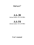
TechnicalReview Product by Mark Spencer, WA8SME Mark J. Wilson, K1RO, [email protected] A Look at Four Antenna Analyzers Analyze these! Reviewed by Joel R. Hallas, W1ZR Technical Editor, QST [email protected] We’ve looked at antenna analyzers, along with other antenna measurement equipment, many times in the past, and we will continue to as new gear becomes available.1 This is a very popular category — all active amateurs must deal with antennas, and an antenna analyzer can make it much easier to find out what’s happening with them. A number of devices can be used to characterize antenna systems, including the SWR metering capability in many HF transceivers. What sets an antenna analyzer apart from SWR and power meters is that the analyzer contains its own signal source. Having its own low level signal source allows measurements outside of amateur bands, often helpful during antenna development, without risk of causing harmful interference. These analyzers are compact and self contained. They include internal power sources, allowing their use on the roof or at the top of a tower. Two of the units reviewed here, the MFJ and RigExpert are updates to analyzers in exist1For example, see J. Hallas, W1ZR, “Product Review — Two More Antenna System Measurement Devices,” QST, Aug 2008, pp 43-47 and “Product Review — A Look at Some High-End Antenna Analyzers,” QST, May 2005, pp 65-69. QST Product Reviews are available to ARRL members online at www.arrl.org/product-review. ing product lines, while the Comet and Ten-Tec are new entries. Although they are similar at first glance, significant differences among the units provide clear choices depending on your interests. COMET CAA-500 STANDING WAVE ANALYZER Comet, a longtime antenna and accessory manufacturer, has joined the antenna analyzer marketplace with the CAA-500. This unit measures SWR and magnitude of impedance across the widest frequency range of the units in this test. Our unit covered 1.53 to 508 MHz in seven overlapping ranges except for a gap from 259.4 to 273.4 MHz. While the manufacturer indicates that the unit can measure SWR from 1:1 to ∞ (infinity), there are no numbers above 6:1, so readings above 6:1 are indications, but not quite measurements, in our view. The frequency is adjusted using a thumbwheel knob that can be tuned by the same hand that holds the unit — very convenient if you are also hanging onto a tower or ladder, for example. The frequency is indi- Bottom Line This is an easy unit to like. Within the limits noted, it is easy to set and easy to read while making antenna or tuner adjustments. It doesn’t offer all the measurement capabilities and other functionality of some of the other units, but it does what it does quite nicely. cated on a seven digit frequency counter, while the SWR and impedance magnitude are shown on a large two scale cross-needle analog meter. There are two coaxial connectors provided, a UHF (SO-239) type for the lower six bands and a Type N socket for 225 to 500 MHz. The unit can be powered by six internal AA size alkaline batteries or an external 8 to 16 V dc power supply via a coaxial power connector. A power cable with matching plug and pigtail leads is provided as is a handy wrist strap. On the Bench We found that the unit had excellent frequency accuracy, within a few Hz, along with easy setability, especially on the lower bands. On the 225 to 500 MHz range it was difficult to set it within 50 kHz, but that shouldn’t be a problem for most antenna work in that range. The frequency stability had similar results. It was quite steady in the lower ranges, but we observed drift of 250 kHz during 5 minutes at 440 MHz. The frequency counter on the unit follows the drift so you know the actual frequency as it moves. The frequency counter has two positions, SLOW and FAST, set by a front panel button. In the FAST position, which easily follows tuning, at least on the lower bands, the counter resolution is 1 kHz. In the SLOW position, it reads to 100 Hz, dropping the hundreds of megahertz digit on the higher bands. Table 1 Antenna Analyzer Feature Comparison Analyzer Price Range MHz SWR Z X Sign of X AA Batt External Power Socket PC I/O Storage Locations Comet CAA-500 $420 1.53-259 273-508 1-6 Yes No N/A 6 Yes UHF/N* No No MFJ-266 $320 1.5-71 85-185 300-490 1-9.9 Yes Yes No 8 Yes N** No No RigExpert AA-54 $320 0.1-54 1-10 Yes Yes Yes 2 Yes UHF Yes 100 Youkits FG-01 $249 1-60 1-9 Yes No No 3*** Yes BNC No No *Type N for top frequency range only. **Type N to UHF adapter provided. ***Requires 3.6 V lithium batteries, type 14500. QST – Devoted Entirely to Amateur Radio www.arrl.org March 2012 1 The steady output level makes it a natural for use as an accurate signal generator for receiver alignment. The addition of a calibrated step attenuator would result in a test instrument that could be used for sensitivity measurement. When testing the receiver portion of a transceiver, be sure to disable the transmitter to heed Comet’s warning about applying RF power to the unit. While we didn’t test this analyzer as a dummy load, I can almost guarantee it won’t make it. The impedance meter can also be used to measure the reactance of a capacitor or inductor, as long as you know which it is. Change the frequency until you have the meter in an easy to read region and you will know the reactance at that frequency. Use the appropriate reactance formula and you will know the value of the capacitor or inductor. Documentation The CAA-500 comes with a clearly written four page Instruction Manual that includes specifications, identification of each connector and control and a short discussion of how to use it. There are also some frequently asked questions (FAQ) that may be helpful. While not a lot of information is provided, the operation of the analyzer will be intuitive to most amateurs who knew they wanted to buy one. Manufacturer: NCG Companies, 15036 Sierra Bonita Ln, Chino, CA 91710; tel 800-962-2611, fax 909-393-6136; www.cometantenna.com. MFJ-266 HF/VHF/UHF ANTENNA ANALYZER MFJ arguably offers the widest selection of antenna analyzers known to man. They have models covering a wide price and capability range starting with their entry level HF analog tuning, SWR-only metering unit at under $100 and ranging up to the MFJ269PRO HF/VHF/UHF multifunction digital display meter in the $400 range. A look at our Product Review archive (www. arrl.org/product-review) will find reviews of a number of representative models. The MFJ-266 falls near the higher end of the product line. It includes many features of the MFJ-269 at a lower price and in an entirely new, more compact envelope with a different control layout. Features include the capability to measure not only SWR, but also the magnitude of impedance, as well as the rectangular resistive and reactive values. The two-line LCD simultaneously displays the frequency, tuning band, complex impedance, magnitude of impedance and SWR — no need to change settings, it’s all there. Note that while a plus sign is shown with the reactive component, they describe it as a “place holder.” You will need to determine the actual sign by other means such as changing the frequency slightly and noting the direction of reactance change. Very useful features beyond the comprehensive SWR functionality mentioned above include the use of the ’266 as a frequency counter. By selecting the appropriate buttons of the BAND button set and the DOWN button Bottom Line The MFJ-266 can serve as the “Swiss Army Knife” in your Amateur Radio tool kit. Either by itself or with available options it can perform many functions to keep your antennas and station equipment at peak performance. Comet CAA-500 SWR/Impedance Analyzer Manufacturer’s Specifications Measured in the ARRL Lab Frequency range: 1.5-500 MHz. 1.532-259.4 and 273.4-508 MHz. SWR measurable range: 1.0-∞. As specified, numerical indication to 6:1. Impedance range: 12.5-300 W. As specified. Impedance accuracy: Not specified. See Table 2. Output power: 0 mW (0 dBm) max, load not specified. 0.5 mW (–3 dBm) into 50 W at 14 MHz. 0.44 mW (–3.5 dBm) to 50 W at 144 MHz. 0.59 mW (–2.3 dBm) to 50 W at 440 MHz. Power requirements: 8-16 V, <180 mA. 165 mA at 13.8 V dc (external power); 167 mA at 9 V dc (internal batteries). Size (HWD): 7.5 × 3.6 × 2.5 inches, weight 1.75 lb. MFJ-266 Antenna Analyzer Manufacturer’s Specifications Measured in the ARRL Lab Frequency range: 1.5-71, 85-185, 300-490 MHz. 1.52-71.7, 85-185, 248-530 MHz. SWR measurable range: 1.0-9.9:1 As specified. Impedance range: Not specified. 5-200 W. Impedance accuracy: Not specified. See Table 2. Output power: 1.6 mW (+2 dBm), load not specified. 2.3 mW (+3.6 dBm) into 50 W at 14 MHz; 1.6 mW (+2.0 dBm) into 50 W at 144 MHz; 0.8 mW (+0.7 dBm) into 50 W at 440 MHz. Power requirements: 10.8-13 V dc (maximum), current, not specified. Analyzer mode: backlight on, 152 mA, backlight off, 126 mA; field strength mode: backlight off, 41 mA; all at 12 V dc. Size (HWD): 6.8 × 4 × 3.2 inches (including protrusions); weight, 1.3 lb. 2 March 2012 ARRL – the national association for Amateur Radio www.arrl.org after power up you enter frequency counter mode. In addition to the observed frequency, the display shows the relative strength of the signal. This can be useful to identify a strong received signal that could interfere with antenna measurements. By pressing the UP button at power on, the ’266 will measure capacitance directly in picofarads. Similarly, pressing the DOWN button at power on switches to inductance measurement mode — both very handy features, calculator not required! Again, you need to know which type (inductance or capacitance) it is to get the correct answer. Setting Up the MFJ-266 When the ’266 is powered up, the display prompts you, once you know the code, to tell it what you want, starting with the BANDMODE SELECT buttons. If you press both the UP and DOWN buttons immediately on power up, it will turn on the backlight — the default is BACKLIGHT OFF to conserve battery power. The available dc voltage is shown, along with an indication that you should push UP to select frequency counter mode or DOWN to select antenna analyzer mode. Frequency is selected from the eight bands by first using the A and B buttons to select HF, VHF, UHF or COUNTER as indicated in the table next to the buttons. While the VHF (85-185 MHz in their definition) and UHF (300-490 MHz) ranges are tuned in one band each, the HF range (1.5-65 MHz) is covered in six bands selected by the UP and DOWN buttons identified as BAND-MODE SELECT in the unit’s center. Once you select the range, you tune the frequency using the TUNE knob. The TUNE knob is part of a 10-turn assembly that permits fine adjustment, but it is tricky to set the exact frequency you want especially on the higher bands. Interestingly, on the “HF” bands, turning the knob clockwise decreases the frequency, while on the VHF and UHF bands it works the other way. Note that all US amateur bands from 160 meters to 70 cm are covered, except 222 MHz. Even though the specifications (and band switch) allowed for a gap from 65 to 85 MHz, our unit covered up to 72 MHz, nicely extending through the UK 4 meter band (70-70.5 MHz). Power Requirements A somewhat surprising external power requirement is worth noting. The manual states that the external dc supply (plugged into a front panel coaxial jack) needs to be between 10.8 and 12.5 V and offers a warning that it can’t be higher than 13 V without load. Since most amateur station dc power supplies deliver 13.8 V or more, this may be a problem for some applications unless special care is taken. The manual also notes that the usual rechargeable 1.2 V NiCd cells will not provide enough voltage for operation. Earlier units could operate from 11 to 18 V. Documentation The MFJ-266 comes with a 20 page instruction manual that includes not only instructions but application notes on how to perform the many tasks that this analyzer can accomplish. The instructions are well written, clear and will be needed to be able to make best use of the unit and all its capabilities. Manufacturer: MFJ Enterprises, PO Box 494, Mississippi State, MS 39762, tel 800-647-1800; www.mfjenterprises.com. RIGEXPERT AA-54 ANTENNA ANALYZER The AA-54 is very different from the other analyzers in this report, although there is a large functional overlap. It is similar to the AA-200 that we reviewed in August 2008, and which is still available. The AA-54 is part of a family of analyzers that cover different frequency ranges, the upper limit of each identified in the numerical portion of the model designator. Now included in the series are the AA-30, 54, 200, 230, 230PRO, 500 and 520. As you might expect, the price increases, as do the features, as you move up the list. They are described and compared on Bottom Line The AA-54 is a very competent, accurate and easy to use analyzer providing single or multi-frequency pointed or plotted SWR and impedance data on a useful LCD display. In the shack or lab, it can also provide more advanced features while connected to a PC using the supplied software. the RigExpert website (www.rigexpert. com). While the AA-200 included a padded case and rechargeable batteries, the AA-54 is supplied with neither — part of the reduced price. The first difference you would encounter between using the AA-54 and the other units in this review is that instead of a tuning knob to select frequency, there is a keypad. This is a mixed blessing — it takes a bit longer to fine tune frequencies, but the frequency you get is the one you actually want and it stays put until you change it. In addition, if you’re not sure exactly what frequency you want to check, you can perform a sweep function to look at the SWR or impedance over a wide range of frequencies and then zero in on the frequency that needs the most attention. On the Bench Our AA-54 showed remarkable frequency accuracy and setability. At 10 MHz, we found the frequency accuracy to be within 800 Hz of the displayed frequency, quite appropriate for its 1 kHz resolution, expanding to be within 6.5 kHz at 54 MHz. It also stayed on frequency, exhibiting virtually no drift throughout our testing. The total output level was +12.3 dBm, ± 0.1 dBm, over the entire operation range, although there was Rig Expert AA-54 HF Antenna Analyzer Manufacturer’s Specifications Measured in the ARRL Lab Frequency range: 0.1-54 MHz. 1.5-54 MHz (usable range). SWR measurable range: 1:1-10:1 As specified. Impedance range: 0-1000 W. As specified. Impedance accuracy: Not specified. See Table 2. Output power: 20 mW (+13 dBm), 50 W load. 17 mW (+12.3 dBm) see text, 50 W (1.5-54 MHz). Power requirements: Two 1.5 V alkaline AA batteries, two 1.2 V NiMH AA batteries, or external power via USB port. Measurement mode: 244 mA backlight on, 169 mA backlight off; standby, 60 mA (backlight off); all at 3 V dc. Size (HWD): 8.5 × 3.8 × 1.5 inches (including protrusions); weight, 14 oz with batteries. QST – Devoted Entirely to Amateur Radio www.arrl.org March 2012 3 high harmonic and spurious content in the output. The measured output level of just the desired signal ranged from +12.3 dBm at 100 kHz to +11.5 dBm at 10 MHz. From 15 to 30 MHz it ranges from +1.5 to +2.5 dBm, while from 35 to 54 MHz it is in the –2.0 to –2.5 dBm range. This did not seem to cause any problems with impedance measurements, perhaps due to internal processing, but could make for confusion if the AA-54 is used as a signal generator. Operator interaction is provided through a custom key pad and monochrome LCD screen. A single UHF connector on the top goes to the test sample, and a socket for a USB cable is provided for connection to a PC if desired. For most functions, the PC is not necessary. Note that the AA-54 is powered via the USB port when connected. The AA-54 is menu driven (see Figure 1) and can provide bar type graphs or numerical SWR or Z data at one or more frequencies. It can also provide swept frequency data. In operation, I found the bar graphs best for making adjustments, since the display updates rapidly, while the swept data is most useful for a summary of results across a band following adjustment or repair. In the Field Standing wave ratio (SWR) is the meat and potatoes of such a device. Set for a single frequency, the LCD display shows a nice to tune with calibrated bar graph, a large font SWR readout, to three digits and the selected frequency, lest you forget. See Figure 2. Selecting SHOW ALL on the menu provides the details of the impedance being measured. This provides the measurement frequency, the SWR and also your choice of a series or parallel equivalent model of R and X, including sign and even the calculated equivalent capacitance or inductance value. See Figure 3. This is much more useful data than just SWR if you wish to design a network to match the load, for example. Graphing Modes: A plot of SWR (Figure 4) or R ± jX (Figure 5) versus frequency can be easily arranged, again in either series or parallel equivalent model. Unlike many devices, the sign of the reactance is shown as well as its value. MultiSWR Mode: A nice feature of all these units except the AA-30 is that data on multiple distinct frequencies can be observed simultaneously. This can be very useful while making adjustments on multiband antennas. In this case the display shows the frequency and a relative bar graph for each frequency (Figure 6) or the actual numerical SWR value. Without this feature, one often 4 March 2012 Table 2 Impedance and SWR Measurements Load Frequency Comet MFJ-266 CAA-500 RigExpert AA-54 Youkits Agilent 4291B FG-01 (reference)1 50 W 3.5 MHz (1:1 SWR) 14 MHz 28 MHz 50 MHz 144 MHz 223 MHz 440 MHz 50+j0 W (1.0:1) 50+j0 W (1.0:1) 50.0+j0 W (1.0:1) 49+j0 W (1.0:1) 49–j0 W (1.0:1) — 49.8–j0.2 W (1.0:1) 49.8+j1.1 W (1.0:1) 49.8+j2.2 W (1.0:1) 49.7–j4.0 W (1.1:1) — 48 W (1.0:1) 48 W (1.0:1) 48 W (1.0:1) 48 W (1.0:1) — 50+j0 W — — 50+j0 W — (1.1:1) — — 50+j0 W 5 W 3.5 MHz — (10:1 SWR) 14 MHz — 28 MHz — 50 MHz — 144 MHz — 440 MHz — 4+j3 W (>9.9:1) 2+j4 W (>9.9:1) 3+j4 W (>9.9:1) 6+j0 W (7.3:1) 3+j9 W (>9.9:1) (>9.9:1) 5.0+j0.4 W (9.9:1) 5.1+j1.7 W (9.9:1) 5.1+j3.4 W (9.8:1) 5.1+j5.8 W (9.7:1) — 4 W (8.5:1) 4 W (8.5:1) 6 W (8.7:1) 11 W (8.2:1) — 5.1+j0.0 W 5.2+j1.9 W — — — 25 W 3.5 MHz (2:1 SWR) 14 MHz 28 MHz 50 MHz 144 MHz 223 MHz 440 MHz 25 W (1.8:1) 25 W (1.8:1) 26 W (1.8:1) 26 W (1.8:1) 24 W (1.7:1) 32 W (1.5:1) 40 W (1.9:1) 25–j0 W (2.0:1) 23+j12 W (2.2:1) 24+j10 W (2.1:1) 26+j0 W (1.8:1) 26+j10 W (2.0:1) — 25.1+j0.1 W (2.0:1) 25.1+j0.7 W (2.0:1) 25.2+j1.3 W (2.0:1) 25.2+j2.4 W (2.0:1) — 23 W (1.9:1) 24 W (1.9:1) 24 W (2.0:1) 25 W (1.9:1) — 25.1+j0 W 25.2+j2.0 W — — — — (1.5:1) — — — 100 W 3.5 MHz (2:1 SWR) 14 MHz 28 MHz 50 MHz 144 MHz 223 MHz 440 MHz 110 W (1.9:1) 110 W (1.9:1) 105 W (1.9:1) 100 W (1.9:1) 92 W (2.1:1) 80 W (2.4:1) 90 W (2.0:1) 95–j19 W (2.0:1) 90–j33 W (2.1:1) 89–j33 W (2.1:1) 90–j27 W (2.0:1) 74–j41 W (2.1:1) — 99.6+j1.7 W (2.0:1) 99.0+j8.8 W (2.0:1) 97.0+j16.8 W (2.0:1) 92.0+j28.6 W (2.1:1) — 98 W (2.0:1) 98 W (2.0:1) 98 W (2.0:1) 95 W (1.9:1) — 100–j0.2 W 99–j8.9 W — — — — (2.1:1) — — — 50 W (1.0:1) 50 W (1.0:1) 50 W (1.0:1) 50 W (1.0:1) 50 W (1.0:1) 48 W (1.1:1) 50 W (1.1:1) has to cycle through the interacting bands multiple times to get them all right. With the AA-54, you can observe the effects on five bands while you make adjustments. The AA-54 includes a memory capability so that you can store up to 100 display screens. As you store each, you are prompted to tag them with an ID to make sorting them out later easier. They can also be shifted to a PC, great for “as built” or “as adjusted” records for later comparison to see degradation ARRL – the national association for Amateur Radio 50+j0 W 50+j0 W 50+j0 W 50+j0 W 5.1+j0.2 W 5.1+j0.4 W 5.1+j0.7 W 25.1+j0.2 W 25.1+j0.4 W 25.1+j0.7 W 100–j0.9 W 100–j1.8 W 99.9–j3.1 W occurring, or to confirm it hasn’t. Computer Connection The AA-54 comes with a CD that includes two auxiliary programs, described below. The software manual indicates that it can be installed in a PC running Windows 2000, 2003, XP, Vista or 7 as well as Mac OS (version 10.6 recommended). I tried it on Windows XP and Windows 7 machines at my location, and each ran successfully. www.arrl.org Table 2 Impedance and SWR Measurements [continued] Load Frequency Comet MFJ-266 CAA-500 RigExpert AA-54 Youkits Agilent 4291B FG-01 (reference)1 200 W 3.5 MHz (4:1 SWR) 14 MHz 28 MHz 50 MHz 144 MHz 223 MHz 440 MHz 225 W (3.8:1) 225 W (3.8:1) 220 W (3.8:1) 210 W (3.7:1) 175 W (4.1:1) 125 W (4.8:1) 170 W (4.1:1) 160–j94 W (4.4:1) 149–j107 W (4.6:1) 144–j104 W (4.5:1) 132–j100 W (4.3:1) 72–j93 W (4.3:1) — 197.8–j1.7 W (4.0:1) 195.0–j26.1 W (4.0:1) 187.5–j50.3 W (4.0:1) 164.2–j83.4 W (4.2:1) — 205 W (4.0:1) 205 W (4.0:1) 205 W (4.0:1) 195 W (4.0:1) — 189–j45 W — — — — (3.8:1) — — — 1000 W 3.5 MHz — — (20:1 SWR) 14 MHz — — 28 MHz — — 50 MHz — — 883–j184 W (18.7:1) 505–j471 W (18.6:1) 202–j471 W (∞) 53–j270 W (∞) — 998–j33 W — 981–j127 W — 935–j230 W — 825–j373 W 50 – j50 W 3.5 MHz (2.62:1 SWR) 14 MHz 28 MHz 70 W (2.5:1) 75 W (2.8:1) 70 W (2.5:1) 34–j39 W (2.6:1) 33–j51 W (3.5:1) 36–j45 W (2.8:1) 49.0–j46.1 W (2.5:1) 45.5–j51.5 W (2.8:1) 45.8–j46.9 W (2.6:1) 83 W (2.5:1) 89 W (2.7:1) 78 W (2.4:1) 50–j47 W 50 + j50 W 3.5 MHz (2.62:1 SWR) 14 MHz 28 MHz 80 W (2.6:1) 75 W (2.5:1) 90 W (2.5:1) 65+j54 W (2.6:1) 51+j51 W (3.0:1) 54+j59 W (2.9:1) 52.0+j50 W (2.6:1) 55.8+j48.1 W (2.4:1) 72.2+j49.0 W (2.4:1) 92 W (2.5:1) 92 W (2.5:1) 100 W (2.5:1) 201–j1.2 W 201–j4.8 W 200–j9.4 W 199–j16 W 51–j48 W 52+j50 W 53+j48 W 65–j51 W SWR loads constructed in the ARRL Lab were measured on an Agilent 4291B Impedance Analyzer by ARRL Technical Advisor John Grebenkemper, KI6WX. An HP 11593A precision termination was used for the 50 W tests. This termination has a wide frequency range. The disc sets up two programs, LCD2Clip, which brings screen shots from the AA-54’s display directly into the PC (push F and 6 simultaneously on the AA-54 keypad) at which point you can make screen shots to save the screen with your favorite photo program or Windows Paint. That is how Figures 1 through 6 were obtained for this review. The other program is a more interesting tool for many applications. AntScope shows Figure 4 — Plot of SWR versus frequency. 48–j52 W 1The Figure 1 — Main menu screen of AA-54. Figure 3 — Screen shot of SHOW ALL display in series equivalent mode. A parallel equivalent circuit model may also be selected. Note that the sign of the reactance is provided, along with the equivalent capacitance at the selected frequency. Figure 2 — Calibrated bar graph display in single frequency mode. The bars respond almost as quickly as an analog meter making them appropriate for antenna tuner or adjusting the controls of an antenna tuner for minimum SWR. results on a full size PC screen, rather than on a copy of the AA-54’s small native display. This allows viewing results in more detail, but it does take a few moments to display and transfer data. This program operates with the AA-54 in PC mode, so all definition and operation take place from the PC. Figure 5 — Plot of R ± jX versus frequency. Note that the sign of the reactance is shown. Figure 6 — Multi-frequency SWR plot with relative bar graph display. The five frequencies can be anywhere within the meter’s range — very handy for adjusting multiband antennas, especially if they interact. The major functions are similar to the AA-54’s — all manner of impedance related data can be displayed — SWR, Z and R + jX (with sign of X, see Figure 7). The frequency limits can be set from the PC to display any portion of the range up to 54 MHz wide. By moving the curser with the mouse, all the details can be shown at any selected frequency. A rather dramatic departure from the typical antenna analyzer is a time domain reflec- QST – Devoted Entirely to Amateur Radio www.arrl.org March 2012 5 Figure 7 — Antennascope view of the SWR of an antenna over the entire range. Note that European amateur bands are highlighted. Another view provides R, Z and X. The range can be reduced for more detail over a band, for example. Smith chart views are also provided. tometer (TDR) function. This sends a pulse down the line and graphically displays the reflected pulse from any discontinuity along the line. The discontinuity could be an antenna at the end of the line, but of even more interest are any discontinuities between the source and the antenna, likely indicating a cable fault. While the default display goes out to a distance of 900 meters (probably more useful for a telephone company than the typical amateur operator), it can be reduced to show closer indications as shown in Figure 8. In this view it has been changed to use US metrics. This feature is something usually found in much more expensive instruments and has the potential to be a great diagnostic tool. Documentation The AA-54 is provided with a 22 page User’s Manual, also available on their website if you want to look it over before you buy. The manual does a good job of describing the basic functions of the device. In addition, the last eight pages are devoted to using the AA-54 in various applications. This section starts with antennas, but moves Figure 8 — Antennascope in time domain reflectometer (TDR) mode. The TDR provides a radar-like view of cable discontinuities along the line. Here you see the 280 foot run of 0.82 relative velocity coax to the W1ZR 80 meter ground plane antenna. The early blips are the pulse partially reflecting from the impedance bumps going through my bypassed linear amplifier and antenna tuner. At almost three divisions (about 80 feet) out, the pulse encounters my dc grounded lightning arrestor at the entrance panel and then 200 feet of coax to the antenna. The details are shown by mousing the cursor to the discontinuity. Had there been a break, short or other cable problem, this would show you exactly where it was. through measuring characteristics of cables, lumped inductors and capacitors and transformers. Use as an RF signal generator is also described, with some cautions as to waveform. The AA-54 also comes with an 11 page Software Manual that describes how to load and run the programs discussed previously. While LCD2Clip is very simple to use, AntScope offers many features and adjustments. I had no trouble installing, running or using the supplied software, a much smoother experience than during the AA-200 review — thanks RigExpert! Manufacturer: Rig Expert Ukraine Ltd, www.rigexpert.com. Available from Array Solutions, 2611 North Beltline Rd, Suite 109, Sunnyvale, TX 75182; tel 214-9547140; www.arraysolutions.com or Rig Expert Canada, www.rigexpert.net. YOUKITS FG-01 ANTENNA ANALYZER The Youkits FG-01 analyzer is the most compact of the bunch — not a lot bigger than a pack of cigarettes, if I remember them correctly. It is also the least expensive of this group, although it does require an optional battery pack to be self contained. It measures SWR and magnitude of impedance from 1 to 60 MHz, showing the numerical result of each at the chosen center frequency along with a display of the swept frequency results, all on a small but readable color display screen. The FG-01 is very easy to operate. There is a single knob that by default sets the center Youkits FG-01 SWR/Impedance Analyzer Manufacturer’s Specifications Measured in the ARRL Lab Frequency range: 1-60 MHz. As specified. SWR measurable range: Not specified. 1.0-9.0:1 Impedance range: Not specified. 5-350 W. Impedance accuracy: Not specified. See Table 2. Output power: 32 mW max (+15 dBm). 36 mW (+15.5 dBm) into 50 W at 14 MHz. 23 mW (+13.6 dBm) into 50 W at 50 MHz. Power requirements: 400 mA at 10-12.8 V dc. 398 mA at 12.8 V dc (external power); 379 mA at 12.4 V dc (internal batteries). Size (HWD): 4.4 × 2.3 × 2.2 inches (including protrusions); weight: 13.5 oz with internal battery. 6 March 2012 ARRL – the national association for Amateur Radio www.arrl.org Bottom Line This unit shares the measurement capabilities of the Comet, but has a digital rather than analog display, and adds the handy sweep function. The frequency stability and accuracy are notable. It is easy to operate, easy to carry, compact and does what it does quite nicely. frequency of the analysis (this is also the frequency to which the numerical data applies). The tuning is over a single continuous band with the tuning step size set from 1 MHz to 1 kHz in four steps. The steps are selected by pushing the knob for 1 second. The digit that will be changed flashes and the digit can be changed by turning the knob while holding it in. Once the step size is selected, the tuning will be at that step size until you change it. After it is set up the way you want it, pushing down the knob for 1 second will save your settings for the next time you power it up. I found the color display easy to see with one exception. It was sometimes difficult for me to decide which of the two plots was which, since the colors don’t seem that far apart. Fortunately, the manufacturer seems to have anticipated this. If you hold the TUNING knob in while you switch the unit on, it will just plot the SWR, the most useful information for most applications. The impedance is still shown in the numerical data portion of the display. The other aspects of the display are easy to use. It simultaneously displays the center frequency, sweep width, SWR, impedance magnitude (no information on the complex impedance, as with the Comet) and battery voltage. The battery display turns red if the voltage drops below 9.5 V and the SWR changes to red for an SWR of greater than 3:1. On the Bench The detailed lab measurements reflect a very competent instrument. In addition it was noted that the frequency stayed unchanged once set. Of course, many of the others were quite stable over the frequency range of the FG-01 as well. The spectral purity was the best we saw. Documentation The unit is supplied with a five page instruction pamphlet that covers the basic operational details, along with many caution notices. The instructions seem to assume that if you buy one, you already know why you wanted it and what you can do with it. The instructions are available on the Ten-Tec website for a preview. One caution relates to power sources. You are cautioned that the AA size battery holder provided is only for 3.6 V lithium cells, rather than the usual 1.5 V alkaline cells. It also notes that if an external supply is used, it must provide 10 to 12.8 V dc — so it is not compatible with most 13.8 V dc home station systems. Manufacturer: Youkits (www.youkits.com). Sold in the US by Ten-Tec, 1185 Dolly Parton Parkway, Sevierville, TN 37862; tel 800-833-7373; www.tentec.com. Antenna Analyzers If you own a tablet or smartphone with the appropriate application, scan this QR Code to see a video overview of the E lecraft KPA500 amplifier. You can also watch this video on your computer by going http://youtu.be/iHEHqRazv-g Bravo-7K Portable Vertical Dipole Reviewed by H. Ward Silver, NØAX ARRL Contributing Editor [email protected] Planning a beach vacation this past summer created a need for a portable antenna. I had mobile whips and I could maybe string up a wire, but a stand-alone antenna would be more flexible to set up and could become part of my regular portable HF kit. The search was on! My requirements: 40 through 10 meters, including 17 and 12 meters High efficiency without radial wires Light weight One-person assembly and adjustment Pieces sized 4 feet or smaller when disassembled No control boxes or power requirements I found lots of antennas that met some of the requirements, even most, but I was beginning to think compromise was going to be necessary. I recalled that Tom Schiller, N6BT (www. n6bt.com) and Team Vertical (www.k2kw. com) were returning to the antenna business and discovered to my delight that he was just finishing the Bravo-7K. It appeared to satisfy every one of my needs! I arranged to pick up a first-run model at the Dayton Hamvention in May and used it during Field Day at KOØA. It rapidly became clear that the antenna was effective on the air! General Specs and Design The Bravo-7K is 18 feet tall and a bit over 18 feet wide when all of the elements are fully extended for 40 meter operation. (Figure 9 shows the antenna set up for 12 meter operation.) The elements are made of telescoping aluminum tubing held in place with stainless steel hose clamps. The total weight is 13 pounds and the longest piece is 36 inches long. The antenna has a single vertical element and Figure 9 — The Bravo-7K set up on the north shore of Puerto Rico for a CW Sweepstakes contest expedition. The antenna is shown at the lengths needed for 12 meter operation. [H. Ward Silver, NØAX] QST – Devoted Entirely to Amateur Radio www.arrl.org March 2012 7