1
Plena Message Manager
Installation and Operating Manual
en
LBB 1965
Plena Message Manager | Installation and Operating Manual | Important safeguards
en | 3
Important safeguards
1 Read instructions - All the safety instructions for use
should be read before the system is operated.
2 Retain instructions - The safety instructions and
instructions for use should be retained for future
reference.
3 Heed warnings - All warnings on the unit and in the
operating instructions should be adhered to.
4 Follow instructions - All operating instructions and
instructions for use should be followed.
5 Cleaning - Unplug system units from the mains outlet
before cleaning. Do not use liquid cleaners or aerosol
cleaners. Use a damp cloth for cleaning.
6 Attachments - Do not use attachments not
recommended by the product manufacturer as they may
cause hazards.
7 Water and Moisture - Do not use this unit near water, for
example near a bathtub, washbowl, kitchen sink, or
laundry basket, in a wet basement, near a swimming
pool, in an unprotected outdoor installation or any area
which is classified as a wet location.
8 Accessories - Do not place this unit on an unstable stand,
tripod, bracket or mount. This unit may fall, causing
serious injury to a person and serious damage to the
unit. Use only a stand, tripod, bracket or mount
recommended by the manufacturer, or sold with the
product. Any mounting of the unit should follow the
manufacturer's instructions, and should use a mounting
accessory recommended by the manufacturer. An
appliance and cart combination should be moved with
care. Quick stops, excessive force, and uneven surfaces
may cause the appliance and cart combination to
overturn.
9 Ventilation - Openings in the enclosure, if any, are
provided for ventilation and to ensure reliable operation
of the unit and to protect it from overheating. These
openings must not be blocked or covered. The unit
should not be placed in a built-in installation unless
proper ventilation is provided or the manufacturer's
instructions have been adhered to.
10 Power sources - Units should be operated only from the
type of power source indicated on the marking label. If
you are not sure of the type of power supply you plan to
use, consult your appliance dealer or local power
company. For units intended to operate from battery
power, or other sources, refer to the "Installation and
User Instructions".
11 Grounding or polarisation - This unit may be equipped
with a polarised alternating current line plug (a plug
having one blade wider than the other). This plug will fit
into the power outlet only one way. This is a safety
feature. If you are unable to insert the plug fully into the
outlet, try reversing the plug. If the plug still fails to fit,
contact your electrician to replace your obsolete outlet.
Do not defeat the safety purpose of the polarised plug.
Alternatively, this unit may be equipped with a 3-wire
grounding type plug having a third (grounding) pin.
This plug will only fit into a grounding-type power
outlet. This is a safety feature. If you are unable to insert
the plug into the outlet, contact your electrician to
replace your obsolete outlet. Do not defeat the safety
purpose of the grounding-type lug.
Bosch Security Systems | 2003-09 | 9922 141 50502en
12 Power-Cord Protection - Power supply cords should be
routed so that they are not likely to be walked on or
pinched by items placed upon or against them, paying
particular attention to cords and plugs, convenience
receptacles, and the point where they exit from the
appliance.
13 Overloading - Do not overload outlets and extension
cords as this can result in a risk of fire or electrical shock.
14 Object and Liquid Entry - Never push objects of any
kind into this unit through openings as they may touch
dangerous voltage points or short-out parts that could
result in a fire or electric shock. Never spill liquid of any
kind on the unit.
15 Servicing - Do not attempt to service this unit yourself as
opening or removing covers may expose to dangerous
voltage or other hazards. Refer all servicing to qualified
service personnel.
16 Damage Requiring Service - Unplug the unit from the
outlet and refer servicing to qualified service personnel
under the following conditions:
• When the power-supply cord or plug is damaged.
• If liquid has been spilled, or objects have fallen into
the unit.
• If the unit has been exposed to rain or water.
• If the unit does not operate normally by following
the instructions for use. Adjust only those controls
that are covered by the instructions for use, as an
improper adjustment of other controls may result in
damage and will often require extensive work by a
qualified technician to restore the units to their
normal operation.
• If the unit has been dropped or the unit has been
damaged.
• When the unit exhibits a distinct change in
performance; this indicates a need for service.
17 Replacement Parts - When replacement parts are
required be sure the service technician has used
replacement parts specified by the manufacturer or parts
which have the same characteristics as the original part.
Unauthorised substitutions may result in fire, electric
shock or other hazards.
18 Safety Check - Upon completion of any service or
repairs to the units, ask the service technician to perform
safety checks to determine that the unit is in proper
operating condition.
19 Lightning - For added protection of the units during a
lightning storm, or when it is left unattended and unused
for long periods of time, unplug it from the wall outlet
and disconnect the cable system. This will prevent
damage to the unit due to lightning and power-line
surges.
Plena Message Manager | Installation and Operating Manual | About this manual
en | 4
About this manual
This manual provides all the information required to install and operate the unit.
Conventions
Warning
Follow these instructions to prevent personal injury.
Caution
Follow these instructions to prevent damage to the equipment.
Note
Read these instructions for tips and other useful information.
Safety precautions
Warning
Do not open the unit when it is connected to the mains. The unit contains non-insulated parts, which can
cause electric shock.
Caution
There are no user-serviceable parts inside the unit. Service must be done by qualified personnel.
Bosch Security Systems | 2003-09 | 9922 141 50502en
Plena Message Manager | Installation and Operating Manual | Table of contents
en | 5
Table of contents
Important safeguards..........................................................................................................................................................3
About this manual ..............................................................................................................................................................4
Safety precautions...............................................................................................................................................................4
Table of contents ................................................................................................................................................................5
1 About the equipment ........................................................................................................................................................7
1.1
Features ......................................................................................................................................................................8
1.2
Capacity .....................................................................................................................................................................8
1.3
Package ......................................................................................................................................................................9
1.4
Controls and indicators (front) ................................................................................................................................9
1.5
Controls and connections (rear) ............................................................................................................................10
2 Installation in rack ...........................................................................................................................................................11
3 External settings and connections .................................................................................................................................12
3.1
Connecting the DC supply (battery) .....................................................................................................................12
3.2
Normal audio connections .....................................................................................................................................13
3.3
Loopthrough audio connections ...........................................................................................................................14
3.4
Trigger input connections ......................................................................................................................................15
3.5
Mains connection ....................................................................................................................................................16
4 Operation .........................................................................................................................................................................17
4.1
Uploading ................................................................................................................................................................17
4.2
Play-back messages .................................................................................................................................................19
4.3
Monitoring ...............................................................................................................................................................20
4.4
Supervision ..............................................................................................................................................................20
4.5
Manual editing of messages ...................................................................................................................................20
5 Technical data ..................................................................................................................................................................22
5.1
Electrical ..................................................................................................................................................................22
5.2
Messages ..................................................................................................................................................................22
5.3
Inputs ........................................................................................................................................................................22
5.4
Outputs .....................................................................................................................................................................22
5.5
Controls ....................................................................................................................................................................23
5.6
Environmental conditions ......................................................................................................................................23
5.7
General .....................................................................................................................................................................23
Bosch Security Systems | 2003-09 | 9922 141 50502en
Plena Message Manager | Installation and Operating Manual | Table of Contents
Bosch Security Systems | 2003-09 | 9922 141 50502en
en | 6
Plena Message Manager | Installation and Operating Manual | About the equipment
1
en | 7
About the equipment
MAINS
F1
Power
230V
Stabiliser
115V
Battery 24V
F2
Stabiliser
18V
Stabiliser
Stabiliser
5V
12V
15 Volt
RS232 to PC
RS232 to LBB 1925
Fault
LED
Trigger Inputs
1
Fault Relay
C
NO
NC
2
3
MSG Active Relay
4
MCU
5
I/O
Expander
6
C
NO
NC
I/O
Expander
1
7
Eeprom
(Flash)
Memory
32 Mbit
Tr. 7
8
Tr. 8
9
10
11
Watchdog
5
7
Tr. 9
9
Tr. 10
11
Tr. 11
12
3
Eeprom
(Flash)
Memory
32 Mbit
Tr. 12
Program
Monitor
1
Watchdog
3
5
7
9
8x DIP
Switch
MCU
Wave Player
DAC
L
R
11
Program
LED
2
4
6
Message
8 LED's
10
12
2
4
6 Trigger
8 LED's
10
12
DAC Supervision
1 Hz
Pilot tone
Detector
Low-pass
20kHz
Pilot tone
Generator
High-pass
Loop-through
Input
Balanced
1
2
3
Output
1
2
3
Balanced
Unbalanced
Unbalanced
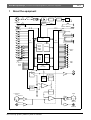
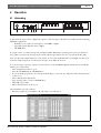
Figure 1.1
Bosch Security Systems | 2003-09 | 9922 141 50502en
Plena Message Manager | Installation and Operating Manual | About the equipment
en | 8
The Plena Message Manager functions as an audio source in the overall Plena PA-system. With this unit it is
possible to play, via other Plena units, pre-recorded messages that are triggered from external sources or the unit's
front panel switches.
These pre-recorded messages (that can be made on a PC in .wav-format) can be used for various purposes, e.g.
routine messages or emergency calls. The messages are stored in solid state memories (Eeproms) and are
continuously supervised on availability.
When the message manager is connected to the Plena System Pre-amplifier (LBB1925), it is also possible to
distribute the messages in pre-programmed zones.
The unit is delivered with the mains voltage selector set to 230 Vac. This selector can be set to 115 Vac.
The unit is not provided with a separate power ON indication. One message LED on the front panel will always be
lit (thus functioning as a power ON indication) as at least one message will be loaded. In case no messages are
loaded, this fault situation is indicated by the fault LED.
1.1 Features
-
Up to 12 different messages can be stored.
Up to 12 message sequences or announcements (each consisting of up to 4 different messages + zone information) can be stored.
Messages can be edited, assembled and uploaded by means of a PC.
The message content is continuously supervised on availability.
The cabling of trigger inputs 1 through 6 can be supervised on cuts and short-circuits.
Mains supply voltage (230/115 Vac) can be supervised.
Pilot tone can be added to supervise the audio connection to an amplifier or the sound system.
Internal pilot tone to supervise the internal audio path.
Support for various sample frequencies to balance audio quality versus message length
1.2 Capacity
The storage device of the messages is a built-in block-erasable EEPROM with fixed storage capacity of 8.38 MByte.
The message manager accepts .wav-files with sample frequencies of 24, 22.050, 16, 12, 11.025 and 8 kHz. The word
length is fixed to 16 bits. This means that the distortion and signal to noise level is of CD quality. Lower sample
frequencies mean a decrease in audio quality (lower bandwidth), but an increase in message length. See the table
below.
Sample frequency
24 kHz
22.050 kHz
16 kHz
12 kHz
11.025 kHz
8 kHz
Audio bandwidth (approx.)
11 kHz
10 kHz
7.3 kHz
5.5 kHz
5 kHz
3.6 kHz
Max. length of all 12 messages
170 s
180 s
250 s
335 s
360 s
500 s
Bosch Security Systems | 2003-09 | 9922 141 50502en
Plena Message Manager | Installation and Operating Manual | About the equipment
en | 9
1.3 Package
The message manager is packed with the following parts:
- 2x RS232 cable for connection with a PC and a system pre-amplifier (9-pin male/female)
- 1x mains cable
- 1x cable with Cinch connectors
- 1x cable with XLR connectors (3-pin male + female)
- 1x Installation and User Instructions
- 2x 19" brackets to install the unit in a 19" rack
- 1x CD-ROM with software to upload messages
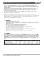
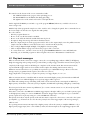
1.4 Controls and indicators (front)
Plena Message Manager
1
2
3
4 5 6
7
8
9
Figure 1.2
1
2
3
4
5
6
Power ON/OFF button
Headphone output socket (6.3 mm phone jack)
Monitor pushbutton (= headphone selection)
Program mode pushbutton
Program mode indicator LED
Fault indicator LED
Bosch Security Systems | 2003-09 | 9922 141 50502en
7 Message indicator LEDs
8 Trigger indicator LEDs
9 Pushbuttons for:
- starting announcements 7-12
- manual (re)programming of trigger inputs 7-12
Plena Message Manager | Installation and Operating Manual | About the equipment
en | 10
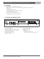
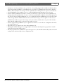
1.5 Controls and connections (rear)
3
9
Loop through
LBB 1965/00
8900 196 5005
Supervision
NC
C
Pilottone
Mains
In
NO
+
24V
Msg Active
NC
C
NO
Fault
13
Trigger Input
1
2
GND
3
4
5
6
7
8
9
10
11
12
RS232 to LBB1925
Trigger Input 1-6
ON
Pilot Message
Tone
1
2
In
4
5
Out
6
8
10
11
Rated Input
Power:50VA
To.5L250V
Warning
RS232 to PC
12345678
7
230V~
115V~ 230V~ 50/60Hz
Apparatus delivered connected for
WK
S/N
OFF
Out
15
This apparatus must be earthed
12
14
16
Figure 1.3
1
2
3
4
5
6
7
Pilot tone volume control
Message volume control
Loopthrough input (Cinch)
Line- and loopthrough output (Cinch)
Loopthrough input (XLR female)
Line- and loopthrough output (XLR male)
DIP-switches (8 pcs) for supervision of trigger inputs
1 through 6, mains and pilot tone
8 24 Vdc input (terminal)
Bosch Security Systems | 2003-09 | 9922 141 50502en
9
10
11
12
13
Message active control output (terminal)
Fault control output (terminal)
Trigger inputs (terminal)
RS232 female socket for connection to a PC
RS232 male socket for connection to a system
preamplifier (LBB1925/10)
14 Earth connection screw
15 Mains voltage selector (115/230 Vac)
16 Mains socket (3 pole)
Plena Message Manager | Installation and Operating Manual | Installation in rack
2
en | 11
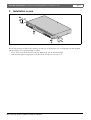
Installation in rack
Ple
na
M
ess
age
Ma
nag
e
r
Figure 2.1
The message manager is delivered for tabletop use, but you can mount it in a 19" rack using the brackets supplied
with the unit. In case of rack mounting, you must:
• remove the 4 feet from the bottom of the unit. Without the feet, the unit is 1U high.
• ensure that the ambient temperature of the unit in the rack does not exceed 55 °C.
Bosch Security Systems | 2003-09 | 9922 141 50502en
Plena Message Manager | Installation and Operating Manual | External settings and connections
3
en | 12
External settings and connections
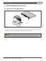
3.1 Connecting the DC supply (battery)
LBB
196
8900 5/00
196
50005
Lo op
In
Pil ot
To ne Mess
age
thr ou
gh
Out
Su pe
rvi sio
Pilo
t tone
Mai
ns
In
Trigg
e r Inpu
Ou t
n
NC C
NO
t 1-6
1 2
3 4
5 6
7 8
+
24V
OFF
12
34
ON
56
78
Ms g
Act ive
NC
C
Trig
ge r
NO
Inpu
Fau
t
lt
1
2
GN D
3
4
5
6
7
8
9
10
11
12
Out
Sup
e rv is
P ilo
t to
M ai ne
ns
In
Trigge
r
Out
Inpu
RS2
32 to
App
aratu
s
io n
NC C
NO
t 1-6
RS2
Ms g
-
1 2
3 4
5 6
7 8
deliv
ere
d con
115V~ necte
d
230V~for 230V~
50/
+
24 V
NC
OFF
12
34
ON
56
78
A ct iv
e
C
T ri gg
N
e r In
Fau O
pu t
lt
1
2
GND
3
32 to
PC
60H
WK.
S/N.
Wa
rnin
This
z
g
appa
ratu
s mus
t be
eart
hed
ated
Pow Input
er:5
T0.5 0VA
L250
V
4
14
12
VD
+
C
F
12
VD
+
F = 1.5 A
C
Figure 3.1
The message manager has a 24 Vdc input (screw terminal), which you can use to connect a back up power supply,
e.g. batteries. You can earth (14) the unit to increase the electrical stability of the system.
Caution
The connection cable must have an in-line fuse. Use the type of fuse as mentioned in the illustration.
Bosch Security Systems | 2003-09 | 9922 141 50502en
Plena Message Manager | Installation and Operating Manual | External settings and connections
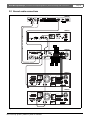
3.2 Normal audio connections
LBB1965
Loop through
LBB 1965/00
8900 196 5005
Supervision
NC
C
NO
+
24V
Msg Active
NC
Pilottone
Mains
In
Trigger Input
C
NO
Fault
1
2
GND
3
4
5
6
7
8
9
10
11
12
230V~
115V~ 230V~ 50/60Hz
Apparatus delivered connected for
RS232 to LBB1925
Trigger Input 1-6
WK
S/N
OFF
Out
ON
Pilot Message
Tone
Out
In
4
2
Rated Input
Power:50VA
To.5L250V
Warning
RS232 to PC
12345678
This apparatus must be earthed
6
LBB1961
Warning
This apparatus must be earthed
LBB1925
Tel/EMG
Trigger 1
Trigger 2
Apparatus delivered
connected for 230V-
LBB1925/10
890019251005
115/230V~,50/60Hz
No.
115V
230V
0
1. Audio+
2.0V
3.Audio4.24Vd.c.
/Line
5. Allcall
6.DataPCAudoln
7.Data+
8.Chs.GND
RS232
CD
Aux
L
/Line
+
2
3
R
7
14
3
5
3
1
5
3
2
GND
1
1
100V 0
100V 0
100V 0
1
2
Rated Input
Power : 50VA
T0.5L 250V
3
100V 0
MasterOut
4
100V 0
+
-
100V 0
100V 0
+24V-
100V 0
6
8
5
4
GND
Out
+24VWarning
This apparatus must be earthed
2
LBB1938
Input 1 Prior ity
Input 1 Input 2 Slave Input
Prior ity Enable 100V
Loopthrough 1
Input 2 Program
Loopthrough 2
2..24V GND 2..24V GND 100V
Default Off Default On
+
-
Input 2 Enable
2..24V-Enable
0V-Mute
+
-
Slave Input 100V 100V
0
Input 1-Prior ity
Input 1 Prior ity
2..24V-Input 1
0V-Input 2
0
100V
0
70V
0
Direct O utput
8ohm
100V/70V
100V 0
Prior ity O nly
0
Input 2-Program
No Pr ior ity
0
70V 0
8
Prior ity Controlled O utput
Prior ity O nly
No Prior ity
100V 0
100V 0
Prior ity
Input
Input
Loopthrough
Loopthrough
Warning
This apparatus must be earthed
LBB1938
Input 1 Prior ity
Input 1 Input 2 Slave Input
Prior ity Enable 100V
Loopthrough 1
Input 2 Program
Loopthrough 2
2..24V GND 2..24V GND 100V
Default Off Default On
+
-
Input 2 Enable
2..24V-Enable
0V-Mute
+
-
Slave Input 100V 100V
0
Input 1-Prior ity
Input 1 Prior ity
2..24V-Input 1
0V-Input 2
0
100V
0
70V
0
Direct O utput
8ohm
100V/70V
100V 0
Prior ity O nly
0
Input 2-Program
No Pr ior ity
0
70V 0
8
Prior ity Controlled O utput
Prior ity O nly
No Prior ity
100V 0
100V 0
Prior ity
Input
Loopthrough
Input
Loopthrough
Warning
This apparatus must be earthed
Figure 3.2
Bosch Security Systems | 2003-09 | 9922 141 50502en
en | 13
Plena Message Manager | Installation and Operating Manual | External settings and connections
en | 14
The message manager can be used with all Plena amplifiers via the Cinch output (4) or the XLR Output (6). The
level of the messages can be set via the message volume control (2).
To fully benefit from the features of the message manager in the overall Plena system (e.g. to distribute pre-recorded
messages to pre-programmed zones) the unit must be connected via the system pre-amplifier LBB1925. To do this,
use the RS232 cable and the audio cable supplied.
There are several ways to connect the message manager to the system pre-amplifier:
- Connecting the Cinch output (4) of the message manager to the Cinch PC Audio In (R) line input of the system pre-amplifier, as shown in figure 3.2 (in which the LBB1961 functions as a BGM source).
- Connecting the XLR output (6) of the message manager to the points 1 and 3 of the 8-pole DIN socket of the
system pre-amplifier.
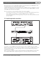
3.3 Loopthrough audio connections
LBB1920
Dir.Out1
Dir.Out2
Dir.Out3
Dir.Out4
Ins/ Casc / Emgln
Ins/ Casc Out
Master Line Out
Master Mic. Out
115V
LBB 1920/00
8900 192 00005
115/230V~,50/60Hz
No.
Ins/Casc
+
14
3
3
5
1
5
14
4
2
3
5
2
-
GND
GND
1
1
3
14
+
-
2
14
3
14
3
5
3
5
3
5
Warning
This apparatus must be earthed
230V
Apparatus delivired
connected for 230V-
Rated input
power: 25VA
T0,5AL250V
L
EMG Out
DC In
DC Out
+24V-
+24V-
R
1/Line
2/Line
3/Line
4/Line
LBB1965
Loop through
LBB 1965/00
8900 196 5005
Supervision
NC
C
NO
+
24V
Msg Active
NC
Pilottone
Mains
In
C
NO
Fault
Trigger Input
1
2
GND
3
4
5
6
7
8
9
10
11
12
230V~
230V~ 50/60Hz
Apparatus delivered connected for
RS232 to LBB1925
Trigger Input 1-6
WK
S/N
OFF
Out
Pilot Message
Tone
ON
Out
In
Warning
RS232 to PC
12345678
This apparatus must be earthed
Rated Input
Power:50VA
To.5L250V
LBB1938
Input 1 Prior ity
Input 1 Input 2 Slave Input
Prior ity Enable 100V
Loopthrough 1
Input 2 Program
Loopthrough 2
2..24V GND 2..24V GND 100V
Default Off Default On
+
-
Input 2 Enable
2..24V-Enable
0V-Mute
+
-
Slave Input
0
Input 1-Prior ity
Input 1 Prior ity
2..24V-Input 1
0V-Input 2
100V 100V
0
100V
0
70V
0
Direct O utput
8ohm
100V/70V
100V 0
Prior ity O nly
0
Input 2-Program
No Pr ior ity
0
70V 0
8
Prior ity Controlled O utput
Prior ity O nly
No Prior ity
100V 0
100V 0
Prior ity
Input
Loopthrough
Input
Loopthrough
Warning
This apparatus must be earthed
Figure 3.3
It is possible to connect the LBB1965 message manager between a mixer pre-amplifier and a power amplifier.
When the message manager is not active, the mixer pre-amplifier is routed to the power amplifier. However, when
the message manager becomes active, this loopthrough connection is interrupted and the message manager is
switched to the power amplifier.
Figure 3.3 shows this configuration example in which the Plena Mixer Pre-amplifier LBB1920 is used with a Plena
Power Amplifier LBB1938. This is a high priority application, as the message manager has absolute priority.
Bosch Security Systems | 2003-09 | 9922 141 50502en
Plena Message Manager | Installation and Operating Manual | External settings and connections
en | 15
3.4 Trigger input connections
Loop through
LBB 1965/00
8900 196 5005
Supervision
NC
Pilottone
Mains
In
C
NO
+
24V
Msg Active
NC
Trigger Input
C
NO
Fault
1
2
GND
3
4
5
6
7
8
9
10
11
12
RS232 to LBB1925
Trigger Input 1-6
Pilot Message
Tone
1
WK
S/N
OFF
Out
ON
In
Out
230V~
115V~ 230V~ 50/60Hz
Apparatus delivered connected for
RS232 to PC
12345678
10
Warning
Rated Input
Power:50VA
To.5L250V
This apparatus must be earthed
11
10kΩ
3.3kΩ
17
Figure 3.4
Message sequences or announcements are started with make contacts (17). These make contacts are connected to
the trigger input screw terminals (11). The cabling of the first six trigger input contacts (1 through 6) can have
supervision by means of a window comparator. Normal operation of these inputs requires two series connected
resistors of 10 kOhm and 3.3 kOhm, permanently connected to the far end of the cable connected to each trigger
input. Triggering occurs by short-circuiting the 10 kOhm resistor as shown in figure 3.4.
Open or short-circuited cables to such an input result in a fault situation that is detected by the window comparator.
The fault indicator LED at the front will light up and the internal fault relay will be unpowered which gives a
contact change on the screw terminals (10) at the rear.
Via the dipswitches 1 through 6 at the rear of the unit supervision of each individual trigger input (1 - 6) can be
enabled ('ON') or disabled ('OFF'). When disabled these inputs act the same as inputs 7 through 12.
Via dipswitch # 7 it is possible to enable mains failure checking. When enabled ('ON') the fault indicator LED at the
front will light up and the internal fault relay will go to the unpowered state upon mains failure, although the unit
may continue to work on the 24 Vdc battery.
When disabled ('OFF') switching between mains and battery operation is automatic and will not be noticed.
Via dipswitch # 8 it is possible to switch ON a 20 kHz pilot tone to the output signal for supervision of the cable by
connecting equipment. The level of the pilot tone is adjustable (from 'OFF' to -14dB with respect to maximum audio
level) via the pilot tone volume control (1). The default volume level is -20 dB.
Bosch Security Systems | 2003-09 | 9922 141 50502en
Plena Message Manager | Installation and Operating Manual | External settings and connections
en | 16
3.5 Mains connection
LBB
196
8900 5/00
196
50005
Lo op
In
Pil ot
To ne Mess
age
thr ou
gh
Out
Su pe
rvi sio
Pilo
t tone
Mai
ns
In
Trigg
e r Inpu
n
NC C
NO
t 1-6
1 2
3 4
5 6
7 8
Ou t
+
24V
OFF
12
34
ON
56
78
Ms g
Act ive
NC
C
Trig
ge r
NO
Inpu
Fau
t
lt
1
2
GN D
3
4
5
6
7
8
9
10
11
12
RS2
32 to
App
aratu
s
deliv
ere
d con
115V~ necte
d
230V~for 230V~
50/
RS2
32 to
PC
60H
z
WK.
S/N.
Wa
rnin
This
g
appa
ratu
s mus
t be
eart
hed
ated
Pow Input
er:5
T0.5 0VA
L250
V
~
15
.
Figure 3.5
Use the supplied mains cord to connect the system to the mains supply.
Note
If necessary set the mains voltage switch (15) to the required voltage using a sharp object, e.g. a small
screwdriver.
Bosch Security Systems | 2003-09 | 9922 141 50502en
Plena Message Manager | Installation and Operating Manual | Operation
4
en | 17
Operation
4.1 Uploading
Plena Message Manager
1
2
3
4 5 6
7
8
9
Figure 4.1
To upload the messages and to configure the sequence of the messages, a PC must be used that meets the following
minimum requirements:
- Pentium processor with a clock frequency of 100 MHz or higher
- Operating system: Windows 95® or higher
- CD-ROM drive
To prepare and to record the messages the standard available Windows® operating system can be used, but it is
also possible to purchase the messages from a studio. All messages must be stored as .wav files in the PC. Only
mono .wav files with sample frequencies of 24, 22.050, 16, 12, 11.025 and 8 kHz and a word length of 16 bits can be
used. The sample frequency for each separate message can be different. See §1.2.
To create messages or message sequences use the software on the CD-ROM supplied with the unit. To install this
software proceed as follows:
• Close all applications that are open.
• Insert the CD-ROM into the CD-ROM drive.
• In case the Setup-program does not start up automatically, go to the next step. Otherwise follow the instructions
on the screen.
• Choose Run from the Start-menu.
• Type 'd:\setup' (where 'd' is the CD-ROM drive).
• Click OK or press Enter.
• Follow the instructions on the screen.
Upon installation proceed as follows:
• Start the program. A screen similar to the following screen will appear.
Figure 4.2
Bosch Security Systems | 2003-09 | 9922 141 50502en
Plena Message Manager | Installation and Operating Manual | Operation
•
•
en | 18
In the left hand part of the screen the messages (max. 12) can be filled out. Proceed as follows:
• Put the cursor in the File box of message # 1.
• Type the message file name and location (or use the Browse box to go to the folder where the message is
stored).
• Proceed in the same way for all necessary messages. The Time, Size and Sample (sample rate) fields will automatically be filled out. During this process the program software will monitor the required memory capacity
and the overall capacity that is available.
In the right hand part of the screen the sequence of the messages can be determined per trigger input. Proceed as
follows:
• Click on the first [▼]-box to invoke a pull-down menu that contains all message numbers that have been filled
out before.
• Select one of the messages.
• Select the next message, using the box to the right hand side of the first [▼]-box,. In this way up to four messages can be selected, thus creating a programmed message sequence. The total time (in s) for this message
sequence will be displayed in the Time field.
• If required click on the appropriate Zone number boxes in order to activate the corresponding zone(s). This
option is only of interest when the message manager is connected to a system pre-amplifier LBB1925.
• Proceed in the same way for the other message sequences.
• By clicking on the Play boxes in both the (left hand) Message screen and the (right hand) Trigger screen, the programmed messages or message sequences will be audible over the PC's loudspeakers. Click again to stop this
action.
The menu bar at the top of the screen provides access to the File menu, the Setup menu and the Help menu.
Upon selection of File a pull-down menu appears with the following options:
- Open: Opens the dialog box to select a configuration file
- Save: Saves the configuration file; it is recommended to create a separate folder for this purpose
- Save as: Opens the dialog box to save the current configuration file
- Save as text file: Opens Notepad for saving the configuration file as a .txt file or for printing; it is recommended
to select font type Arial for optimum alignment
- Exit: Closes the program
Upon selection of Setup a pull-down menu appears with the options to:
- Select the RS232 Com port on the PC
- Select the language on the screen
Upon selection of Help you can select About Plena message manager to display the program release number.
•
•
•
Connect the supplied RS232 cable between the PC and the message manager. Use the RS232 female socket at
the rear of the unit.
Use the Com port selection button (in the pull-down menu under the Setup box) to select Com port 1 or 2 of the
PC.
Click the Send messages and configuration button to transfer the file to the message manager. During this file transfer
-which, depending on the file size of the messages, may take up to 45 minutes (at 115 kbps)- the percentage ready
bar on the screen indicates the progress of the uploading process. During uploading the program mode indicator
LED (5) on the front is lit.The message indicator LEDs (7) on the front of the unit will be continuously lit for
each message that is present and available in the message manager.
Bosch Security Systems | 2003-09 | 9922 141 50502en
Plena Message Manager | Installation and Operating Manual | Operation
en | 19
The status bar at the bottom of the screen contains three fields:
- The STATUS field shows the progress of the uploading process.
- The RS232 PORT shows the RS232 data during uploading.
- The rightmost box of the status bar shows the actual upload time.
On the supplied CD-ROM you can find a copy of the program R8brain (r8brain.exe, available as freeware at
www.voxenga.com).
With the help of this program the sample rate of the .wav files can be changed, if required. It is recommended to use
the lowest sample rate that does not degrade the audio quality.
Proceed as follows:
• Start the program r8brain.exe.
• Browse to the .wav file that must be modified.
• Browse to the folder in which the modified file must be placed.
• If required, change the message file name in the Browse menu.
• Enter the output sample rate in the appropriate field or click on the output sample rate in the pull-down menu
(sample rates like 12 kHz are not in the list, but can be entered from the keyboard).
• Select 16-bit for Output bit depth and High or Very High for Conversion quality.
• Click on Perform r8brain. A progress bar shows the progress of the conversion.
• To convert from stereo .wav files to mono use the program Sound Recorder that comes with Windows®.
Generally, you can find this program via Start > Programs > Accessories > Entertainment > Sound Recorder.
4.2 Play-back messages
When an announcement is started via a trigger contact, the corresponding trigger indicator LED (8) will light up.
Single-shot triggering and repeating mode is provided. After pressing a trigger switch the announcement is played
completely. If the trigger switch is still ON upon completion of the announcement, this announcement will be
repeated until the trigger switch is released. Then it will complete the running announcement and stop.
Within an announcement there is no possibility for repetition loops of individual messages. However the same
message may be programmed in the sequence more than once (max. 4).
Trigger inputs have serial priority, i.e. input 1 has priority over trigger input 2, 2 over 3, etc.
When an announcement is overridden with an announcement with a higher priority, the first indicator LED will
extinguish and the new LED will light up. Lower priority triggers will be ignored.
The LED of the running message is flashing (2 Hz). If the current announcement is interrupted via RS232 by a
higher priority call from the connected system pre-amplifier, the LED will stop flashing and light up continuously.
The front panel of the unit contains six pushbuttons (9) to activate announcements 7 to 12, effectively in parallel
with the trigger inputs 7 to 12.
If the unit is connected to the LBB1925 via RS232, trigger inputs 1 through 6 will be processed with a priority equal
to the high-priority setting of a connected LBB1946 call station. Trigger inputs 7 through 12 are processed with a
priority equal to the low-priority setting of a connected LBB1946 call station.
This priority level affects only the priority of the announcements compared to other sources connected to the system
pre-amplifier, e.g. call stations. It does not affect the priority between the trigger inputs of the message manager,
which is serial.
If a repeating announcement is interrupted by a higher priority call via the system pre-amplifier LBB1925 or by a
higher priority trigger input (lower contact number) and if, after the interruption, the original trigger input is still
Bosch Security Systems | 2003-09 | 9922 141 50502en
Plena Message Manager | Installation and Operating Manual | Operation
en | 20
active, this announcement will start again from the beginning. Non-repeating single-shot announcements are just
cancelled without finishing.
4.3 Monitoring
The message manager comprises a 6.3 mm headphone output socket (2) with a momentary monitor pushbutton (3).
When the unit is not active it is possible to select messages for monitoring. Note that memory supervision
(checksum) is disabled during monitoring.
If during monitoring any trigger input contact for starting an announcement is made, the monitoring process is
cancelled immediately and the normal play-back mode is resumed.
To select messages for monitoring simply press the momentary monitor pushbutton. A single push starts message
#1. If the pushbutton remains pressed, message #2 will be played automatically upon completion of message #1, #3
after #2, etc., up to and including the last available message. Then it stops.
If during play-back of a message the monitor pushbutton is repeatedly pressed, the next message is started without
finishing the previous one. During this monitoring process the corresponding message indicator LEDs are flashing.
Running messages, triggered manually or started via the trigger contacts, can be heard on the monitor headphone as
well. There is no monitor volume control.
4.4 Supervision
In conformity with the major standards for emergency sound systems like IEC 60849, the following features of the
message manager are or can be supervised:
- Content of the message memory. The micro controller adds a checksum to the messages. This supervision
requires no user intervention. If no messages are played the processor will read out the complete audio memory to compare its content to the checksum, automatically and continuously within a 100 s cycle.
- Availability of any message in the audio memory.
- Presence of mains supply.
- Trigger contacts and involved wiring of trigger inputs 1 to 6 (see also §1.4).
- Resetting of the internal processors by the 'watchdog' circuitry. The processors have a watchdog circuit to
reset the processor if the normal program flow is halted or deviated from.
- Supervision of the DAC using a 1 Hz pilot tone.
- Supervision of audio connections using a 20 kHz pilot tone.
If during supervision a fault is pointed out, the fault indicator LED (6) will light up and the internal fault relay, which
is normally activated when the power supply is connected and the unit is ON, will be switched to its unpowered
state.
Potential free fault contacts (SPDT) and potential free message active relay contacts are provided at the rear of the
unit.
4.5 Manual editing of messages
The program mode pushbutton (4) can be used to manually change the message sequence of trigger inputs 7 to 12
and the corresponding zone set-up. Manual editing is not possible for the trigger inputs 1 to 6; these input
configurations must be uploaded from the PC to avoid abuse.
Manual editing of trigger inputs is done as follows:
• Press the program mode pushbutton (4) and keep it depressed for more than 3 s. The program mode indicator
LED (5) will light up to indicate that the message manager is in the program mode.
Bosch Security Systems | 2003-09 | 9922 141 50502en
Plena Message Manager | Installation and Operating Manual | Operation
•
•
•
•
•
•
•
en | 21
Briefly press one of the pushbuttons (9), e.g. #11. The corresponding trigger indicator LED (8) will flash and the
(upper) trigger indicator LEDs 1 to 6 will indicate the stored zones for pushbutton #11. The message indicator
LEDs (7) will only indicate the messages related to pushbutton #11. Their place in the sequence is not indicated.
Use the pushbuttons (9) to toggle the zones 1 to 6 ON and OFF, thus indicating the new zone selection.
Press the monitor pushbutton (3) briefly to clear the present message sequence for the selected pushbutton (9).
Pressing the monitor pushbutton (3) once more causes the message indicator LED #1 to flash; subsequent pressing causes the message indicator LEDs #2, 3, 4, etc. to flash. If the monitor pushbutton is pressed for more than
3 s the message indicator LED that flashed is selected as the first message of a new sequence for the selected
pushbutton (9). In this way up to four messages can be selected in a random order to be part of that announcement. After the fourth message no more messages will be accepted.
Press the program mode pushbutton (4) once again for more than 3 s to enter the new configuration data and to
exit the program mode.
Repeat the above procedure for any of the other pushbuttons (9).
If during this manual editing process a trigger input is activated, the unit will quit the program mode and the
requested announcement will be started.
If in the program mode no pushbutton is pressed for approx. 25 s, the unit will automatically resume its normal
working mode, without storing the new configuration data.
Bosch Security Systems | 2003-09 | 9922 141 50502en
Plena Message Manager | Installation and Operating Manual | Technical data
5
Technical data
5.1 Electrical
Mains voltage
Max mains power consumption
Max mains inrush current
Battery voltage
Max battery current
230/115 Vac, ±10%, 50/60Hz
50 VA
3 A @ 230 Vac / 6A @ 115 Vac
24 Vdc, +20%/-10%
1A
5.2 Messages
Data format
Supported sample rates (fs)
Frequency response @ fs = 24 kHz
@ fs = 22.050 kHz
@ fs = 16 kHz
@ fs = 12 kHz
@ fs = 11.025 kHz
@ fs = 8 kHz
Distortion
S/N (flat at max volume)
Memory capacity
Recording/playback time
Max number of messages
Supervision EEPROM
Supervision DAC
Data retention time
wav-file, 16 bit PCM, mono
24 kHz, 22.050 kHz, 16 kHz, 12 kHz, 11.025 kHz, 8 kHz
100 Hz - 11 kHz (+1/-3 dB
100 Hz - 10 kHz (+1/-3 dB)
100 Hz - 7.3 kHz (+1/-3 dB)
100 Hz - 5.5 kHz (+1/-3 dB)
100 Hz - 5 kHz (+1/-3 dB)
100 Hz - 3.6 kHz (+1/-3 dB)
< 0.1% @ 1 kHz
> 80 dB
8.38 MByte EEPROM
500 s @ fs = 8 kHz - 167 s @ fs = 24 kHz
12
continuous checksum control
1 Hz pilot tone
> 10 years
5.3 Inputs
Loopthrough audio input 1 (3-pin XLR, balanced)
Sensitivity
1V
Impedance
20 kOhm
CMRR
> 25 dB (50 Hz - 20 kHz)
Loopthrough audio input 2 (Cinch, unbalanced)
Sensitivity
1V
Impedance
20 kOhm
5.4 Outputs
Supervision pilot tone
20 kHz, ±10%, level adjustable
Line output 1 (3-pin XLR, balanced)
Nominal level
Impedance
1 V, adjustable
< 100 Ohm
Line output 2 (Cinch, unbalanced)
Nominal level
Impedance
1 V, adjustable
< 100 Ohm
Bosch Security Systems | 2003-09 | 9922 141 50502en
en | 22
Plena Message Manager | Installation and Operating Manual | Technical data
5.5 Controls
Trigger inputs (Screw)
Activation
Supervision
Supervision method
contact closure
on trigger inputs 1-6, selectable
loop resistance check
Control outputs (Screw)
Message active relay
Fault relay
100 V, 2 A (voltage free, SPDT)
100 V, 2 A (voltage free, SPDT)
RS232 (9-pin D-sub)
PC to LBB1965/00
LBB1965/00 to LBB1925/10
115 kb/s, N, 8, 1, 0 (upload)
19.2 kb/s, N, 8, 1, 0 (zone control)
5.6 Environmental conditions
Operating temperature range
Storage temperature range
Relative humidity
-10 to +55 °C
-40 to +70 °C
< 95%
5.7 General
EMC emission
EMC immunity
Dimensions
Weight
19” mounting brackets
acc. to EN 55103-1
acc. to EN 55103-2
56 x 430 x 270 mm (19” wide, 1U high, with feet)
approx. 3 kg
included
Bosch Security Systems | 2003-09 | 9922 141 50502en
en | 23
Plena Message Manager | Installation and Operating Manual |
Bosch Security Systems | 2003-09 | 9922 141 50502en
en | 24
For more information visit
www.boschsecuritysystems.com
© Bosch Security Systems B.V.
Data subject to change without notice
2003-09 | 9922 141 50502en