1
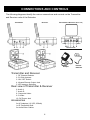
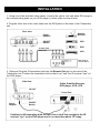
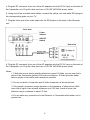
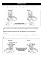
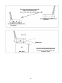
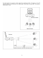
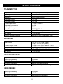
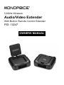
5.8GHz Wireless Audio/Video Extender With Built-in Remote Control Extender PID: 10247 OWNERS MANUAL TABLE OF CONTENTS Introduction 1 Features 2 Package Contents 2 Safety Warnings 3 Connections and Controls 4 Installation 5 Operation 7 Troubleshooting 10 Specifications 11 INTRODUCTION Thank you for purchasing the Monoprice 10247 Wireless Audio/Video Extender! For best results please read this manual carefully, paying extra attention to the safety warnings. Keep this manual in a safe place for future reference. The Monoprice 10247 Wireless Audio/Video Extender adds wireless flexibility to your home audio and video system. It can be used to wirelessly extend the signals from a VCR, satellite receiver, camcorder, and stereo audio components. It operates on the 5.8 GHz wireless frequency band, which is less crowded and has less interference than the traditional 2.4 GHz wireless frequency. This extender has many different applications, including the ability to: Watch a movie on the TV in your bedroom without moving your DVD player Listen to music in the backyard on a pair of powered speakers Watch the game on a portable TV in the garage without running a long cable Use your camcorder to monitor the baby's nap while working in another room 1 FEATURES Avoids the crowded 2.4GHz band by operating at 5.8GHz Compatible with S-Video and Composite video signals Supports 2-channel stereo audio signals Adjustable antenna for improved performance Can be adjusted to operate on any of four different wireless channels Includes a built-in IR remote control repeater Includes AC adapters and AV cables Compatible with 38KHz and 56KHz IR signals PACKAGE CONTENTS Please take an inventory of the package contents to ensure you have all the items listed below. If anything is missing or damaged, please contact Monoprice Customer Service for a replacement. 1x 5.8 GHz Transmitter unit 1x 5.8 GHz Receiver unit 2x AC power adapter (120 VAC/60Hz, 12 VDC/250mA) with 73" cord 2x 3-conductor RCA 45" Audio/Video cables 1x IR Transmitter bulb with 105" cable 2 SAFETY WARNINGS To avoid personal injury or damage to your equipment, please adhere to the following safety guidelines: 1. Do not expose this device to water or moisture of any kind. Do not place objects filled with liquids on or near this device. 2. Do not install this device in an enclosed space. Ensure that there is sufficient ventilation to keep the unit from overheating. 3. Do not place objects on this device or otherwise block the cooling vents. 4. Do not install near any heat sources, such as stoves, radiators, or fireplaces. 5. Do not place naked flames, such as candles, on or near this device. 6. Clean only with a dry cloth. Do not use liquid cleaners or solvents to clean this device. 7. Unplug the unit during lightning storms or when the unit will be unused for a long period of time. 8. Do not allow the power cords to be walked on, pinched, tripped over, or otherwise damaged. 3 CONNECTIONS AND CONTROLS The following diagrams identify the various connections and controls on the Transmitter and Receiver units of the Extender: Transmitter Receiver Transmitter & Receiver (Rear view) Accessories Adaptor Transmitter and Receiver 1. RF Channel Selector 2. 5.8 GHz Antenna 3. ON / OFF Switch 4. Infrared Remote Output Jack 5. IR Frequency Selection Rear view of Transmitter & Receiver 6. Audio L 7. Audio R 8. Composite Video 9. S-Video 10. DC Power Jack Accessories 2x AC Adapters (12 VDC, 250mA) 1x IR Transmitter Bulb 2x Audio/Video Cables 4 Infrared Extender INSTALLATION 1. Using one of the included video cables, connect the yellow, red, and white RCA plugs to the corresponding jacks on your DVD player (or other video source device). 2. Plug the other end of the video cable into the RCA jacks on the back of the Transmitter unit. Rear View Satellite Receiver Power Adaptor VCR ON/OFF Switch DVD S-Video cable RCA cable VCD Rear view of source device 3. (Optional) Plug the IR transmitter bulb into the Remote Out jack on the side of the Transmitter unit. Position the transmitter bulb so that it can "see" the IR receiver "eye" on the DVD player. Side View Cable, Satellite Receiver, DVD player, VCR, VCD IR OUT Front View Power Adaptor ON/OFF Switch Position the IR transmitter bulb so that it has a clear line-of-sight to the IR receiver "eye" on the DVD player and is no more than about 18" away. 5 4. Plug the DC connector from one of the AC adapters into the DC 5V input on the back of the Transmitter unit. Plug the other end into a 100-120 VAC/60Hz power outlet. 5. Using one of the included video cables, connect the yellow, red, and white RCA plugs to the corresponding jacks on your TV. 7. Plug the other end of the video cable into the RCA jacks on the back of the Receiver unit. Rear View Power Adaptor ON/OFF Switch Rear View S-Video cable RCA cable 5 8. Plug the DC connector from one of the AC adapters into the DC 5V input on the back of the Transmitter unit. Plug the other end into a 100-120 VAC/60Hz power outlet. Notes: 1. If both the source device and the television support S-Video you can use that in place of the Composite (yellow) RCA video connection. S-Video provides better picture quality so should be used whenever possible. 2. Do not use both a Composite and S-Video connection at the same time. 3. The system's maximum range depends on the presence of obstructions. With clear line-of-sight it can achieve distances up to 200 feet. Inside a home, the effective range is reduced to about 75 feet. 4. Do not make any connections to the Receiver or Transmitter while either unit is powered on. 6 OPERATION 1. Use the Channel Selection switch on the Transmitter to select one of the four wireless channels. Set the Channel Selection switch on the Receiver to the same channel. Transmitter Receiver Channel selection button must be set to the same channel on both the transmitter & receiver. 2. Pull the antenna out of the base of the Transmitter until the face is vertical. Rotate the antenna until the side with the dot (the inside part) is facing the location of the Receiver unit. Caution! The antenna does not rotate 360 degrees. Do not force it past any resistance. 3. Pull the antenna out of the base of the Receiver until the face is vertical. Rotate the antenna until the side with the dot (the inside part) is facing the location of the Transmitter unit. Receiver Transmitter Side with round dot Turn the side with round dot face-to-face to obtain the best performance. 7 For best performance position the antennas so that they are face-to-face (the side with the dot). Receiver Transmitter Receiver IR Receiver TV For best IR reception performance the Receiver unit should be positioned so that the front is slightly ahead of the Television screen. Side View 8 For best results, the remote control should be positioned within 15 degrees of the IR sensing window on the Receiver unit. Additionally, it should be no closer than 1 foot and no further than 15 feet. IR sensor window Remote Control Receiver Distance not less than 1 foot and no more than 15 feet 9 TROUBLESHOOTING No picture or sound a) Check the power on/off switches on the Transmitter, Receiver, source device, and TV. b) Make sure the power plug and signal cables are pushed all the way in. c) Check that the transmitter & receiver are set to the same wireless channel. d) Make sure that all cables are connected as per the installation instructions. e) Ensure that the range between the transmitter and receiver is not excessive. Try moving the units closer together and eliminate any line-of-sight obstructions. f) If you use the S-Video connection, ensure your TV is set to "S-Video" mode. Interference & noise a) Adjust the receiver antenna direction for optimal performance. b) Adjust transmitter antenna direction for optimal performance. c) Verify that the supplied voltage matches the adapter requirements. d) Select a different wireless channel by sliding the channel button on both the transmitter and receiver. e) Try moving the transmitter / receiver position for optimal performance. f) If the distance between receiver and transmitter is less than 30 feet, leave the antennas stored inside the base, as the signal could be too strong to obtain a sharp picture. Remote control extender does not work 1) To ensure good infrared remote control operation aim your remote control at the IR Sensor Window on the Receiver and press the buttons firmly. With some remote controls it may be necessary to press and hold each button for about a second. The working angle of the IR Sensor Window is +/- 15 degrees. 2) Check the path between the transmitter & receiver and clear unnecessary obstructions. 3) Make sure the IR extender bulb is pointing toward the sensor of device. 4) Try replacing the batteries in the remote control with new batteries. 5) The optimum indoor operating range is about 45 feet. 6) Change the IR carrier frequency on the transmitter. 10 SPECIFICATIONS TRANSMITTER Output Level 13dBm (complies with CE) Operating Frequencies 5790, 5828, 5847, and 5866 MHz Modulation FM (Video and Audio) Video Input Level 1.0 V p-p Audio Input Level 1.0 V p-p S-Video Input Level Y:1Vpp, C:288mV Video Input Impedance 75 ohm Audio Input Impedance 2K ohm Power Consumption DC 12V@250mA Unit Dimensions 4.7" x 3.9" x 1.7" (12 x 10 x 4.3 cm) Unit Weight 7.1 oz. (200g) Effective Operating Range Approx. 200 feet (clear line of sight) RECEIVER Output Level 1.0V p-p +/- 0.2V p-p (Video) 1.0Vp-p +/- 0.2V p-p (Audio) S-Video Output Level Power Consumption Unit dimensions Unit weight Y:1Vpp+/-0.2V p-p, C:288mV +/-20% 12V DC@250mA 4.7" x 3.9" x 1.7" (12 x 10 x 4.3 cm) 7.1 oz. (200g) IR TRANSMITTER Output Level Operating Frequency Modulation Type IR Carrier Frequency Effective Operating Range 0~10dBm 433.92MHz AM 38KHz / 56KHz Switchable Approx. 100 feet(clear line of sight) IR RECEIVER Operating Frequency Sensitivity IR Carrier Frequency 433.92MHz <-80dBm 38KHz /56KHz Switchable 11