1
lVLAG
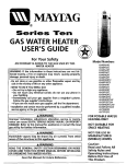
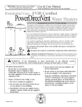
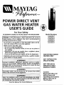
POWER DIRECT VENT
GAS WATE
USER'S HEATER
UIDE
For Your Safety
AN ODORANTIS ADDEDTO THEGAS USEDBYTHISWATERHEATER
WARNING: If the information in these instructions are not followed exactly, a fire or explosion may result, causing property
damage, personalinjury or death.
-Do not store or use gasoline or other flammable vapors and liquids in the vicinity of this or any other appliance.
-WHAT TO DO IFYOU SMELLGAS
• Do not try to light any appliance.
• Do not touch any electrical switch; do not use any phone in
your building.
• Immediately call your gas supplier from a neighbor's phone.
Follow the gassupplier'sinstructions.
• If you cannot reachyour gassupplier,call the fire department.
-Installation and servicemust be performed by a qualified installer,
service agency or the gas supplier.
AWARNING
Model Numbers
HJ640NBDVT
HJ640PBDVT
HJ650NBDVT
HJ650PBDVT
HJ675NRDVT
HJ675PRDVT
FOR POTABLE WATER
HEATING ONLY
NOT SUITABLE FOR
SPACEHEATING
Improper installation, adjustment, alteration, service or maintenance can cause DEATH, SERIOUS BODILY INJURY,OR PROPERTY
DAMAGE. Refer to this manual for assistance or consult the local
gas utility for further information.
MANUFACTURED
(MOBILE) HOMES
Flammable vapors may be drawn by air currents from
areas of the structure to •,WARNING
this appliance.
other
Caution:
Read and Follow All
READ THE GENERAL SAFETY SECTION BEGINNING ON INSIDE
COVER AND THEN THIS ENTIRE MANUAL BEFORE INSTALLING
OR OPERATING THIS WATER
HEATER.
•,WARNING
Save this Manual for Future Reference.
NOT FORUSEIN
Operating Instructions
Before First Use of
This
Product.
Safety
Rules and
Safety Instructions
A WARNING
_WARNING
Improper installation, adjustment, alteration, service
or mamtanance can cause DEATH, SERIOUS BODILY
INJURY, OR PROPERTY DAMAGE. Refer to this manual for assistance consult your local gas utility or call
Maytacl Customer Service at 1-800-788-8899 for an
authonzed servicer for further information,
At the time of manufacture this water heater was provided with a combination temperature-pressures relief
valve certified by a nationally recognized testing laboratory that maintains periodic inspection of production
of listed equipment or materials, as meeting the
requirements for Relief Valves and Automatic Gas
Shutoff Devices for Hot Water Supply Systems, and I
the latest edition of ANSI Z21.22 and the code require- I
ments of ASME. If replaced, the valve must meet the I
requirements of local codes, but not less than a combination temperature and pressure relief valve certified
as meeting the requirements for Relief Valves and
Automatic Gas Shutoff Devices for Hot Water Supply I
Systems, ANSI Z21.22 by a nationally recognized test- [
ing laboratory that maintains periodic inspection of
production of listed equipment or materials.
I The valve must be marked with a maximum set pressure not to exceed the marked hydrostatic working
pressure of the water heater (150 Ibs./sq. in.) and a
discharge capacity not less than the water heater
input rate as shown on the model rating plate.
(Electric heaters - watts divided by 1000 x 3415 equal
BTU/Hr. rate.)
Your local jurisdictional authority, while mandating the I
use of a temperature-pressure relief valve complying J
with ANSI Z21.22 and ASME, may require a valve model I
different from the one furnished with the water heater. I
Compliance with such local requirements must be sat- I
isfied by the installer or end user of the water heater I
with a locally prescribed temperature-pressure relief I
valve installed in the designated opening in the water I
heater in place of the factory furnished valve.
I
For safe operation of the water heater, the relief valve I
AWARNING
WATER HEATERS EQUIPPED FOR ONE TYPE GAS
ONLY: This water heater is equipped for one type
gas only. Check the model rating plate near the gas
control valve for the correct gas. DO NOT USE THIS
WATER HEATER WITH ANY GAS OTHER THAN THE
ONE SHOWN ON THE MODEL RATING PLATE. Failure
to use the correct gas can cause problems which can
result in DEATH, SERIOUS BODILY INJURY, OR PROPERTY DAMAGE. If you have any questions or doubts
consult your gas supplier or local utility,
AWARNING
INSTALLATIONS IN AREAS WHERE FLAMMABLE LIQUIDS (VAPORS) ARE LIKELYTO BE PRESENTOR STORED
(GARAGES, STORAGE, AND UTILITY AREAS, ETC):
Flammable liquids (such as gasoline, solvents, propane
(LP) or butane, etc.), all of which emit flammable
vapors, may be improperly/stored
or used in such
areas. The gas water heater tc_nitoror main burner can
ignite such vapors. The resulting flashback and fire can
wellcauSeasdeathproperty°r
toyour
anyone
the area,
as
If installation inserioUSdamage.burns
such areas is
onlyinoption,
then
the installation must be accomplished in a way that
the ignitor and main burner flame are elevatedfrom
the floor at least 18 inches. While this may reduce the
chances of flammable vapors from a floor spill being
ignited, gasoline and other flammable substances
should never be stored or used in the same room or
area containing a gas water heater or other open
flame or spark producing appliance,
NOTE: Flammable vapors may be drawn by air currents
from other areas of the structure to the appliance,
must
not be removed from it's designated opening or I
plugged.
The temperature-pressure
relief valve must be
installed directly into the fitting of the water heater
designated for the relief valve. Position the valve
downward and provide tubing so that any discharge
will exit only within 6 inches above, or at any distance
below the structural floor. Be certain that no contact is
made with any live electrical part. The discharge opening must not be blocked or reduced in size under any
circumstances. Excessive length, over 30 feet, or use of
more than four elbows can cause restriction and
reduce the discharge capacity of the valve.
No valve or other obstruction is to be placed between
the relief valve and the tank. Do not connect tubing
directly to discharge drain unless a 6 air gap is provided. To prevent bodily injury, hazard to life, or property
damage, the relief valve must be allowed to discharge
water in quantities should circumstances demand. If
the discharge pipe is not connected to a drain or other
suitable means, the water flow may cause property
damage.
The Discharge Pipe:
• Must not be smaller in size than the outlet pipe size
of the valve, or have any reducing couplings or
other restrictions.
• Must not be plugc_edor blocked.
• Must be of matenal listed for hot water distribution.
AWARNING
If this water heater will be used in beauty shops,
barber shops, cleaning establishments, or self-setvice laundries with dry cleaning equipment, it is
imperative that the water heater or water heaters
be installed so that combustion and ventilation air
be taken from outside these areas, Refer to the
"Locating The New Water Heater" section of this
manual and also the latest edition of the National
Fuel Gas Code, ANSI Z223.1, also referred to as NFPA
54 for specifics provided concerning air required,
AWARNING
A fire can start if combustible materials such as
clothing, cleaning materials, or flammable liquids
are paced against or next to the water heater.
2
of
both
temperature-pressure
relief valve,
and
Must
be the
installed
so as to allow complete
drainage
the discharge pipe.
Must terminate at an adequate drain.
Musttank.
not have any valve between the relief valve
and
Safety Instructions
AWARNING
AWARNING
Do not install in a confined area such a closet, unless
you provide ventilation
air as shown in the
"Locating The New Water Heater" section. Never
obstruct the flow of ventilation air. If you have any
doubts or questions at all, call your gas company,
Failure to provide ventilation air can result in a fire
or explosion and can cause DEATH, SERIOUS BODILY
INJURY,OR PROPERTY DAMAGE,
This water heater must not be installed directly on
carpeting. Carpeting must be protected by a metal
or wood panel beneath the appliance extending
beyond the full width and depth of the appliance by
at least 3 inches (76.2mm) in any direction, or if the
appliance is installed in an alcove or closet, the
entire floor must be covered by the panel. Failure to
heed this warning may result in a fire hazard.
I
_,WARNING
A'WARNING
The power direct vent water heater requires its own
(separate) venting system. It cannot be connected to
an existing vent pipe or chimney. It must be terminated to the outdoors. Failure to properly install the
ventin_ system can result in asphyxiation, a fire or
explosion and can cause DEATH, SERIOUS BODILY INJURY, OR PROPERTY DAMAGE.
HOTTER WATER CAN SCALD: Water heaters are
intended to produce hot water. Water heated to a
temperature which will satisfy clothes washing, dish
washing, and other sanitizing needs can scald and
permanently injure you upon contact. Some people
are more likely to be permanently injured by hol
water than others. These include the elderly, children
the infirm, or physicall_//mentally handicapped. It
anyone using hot water in your home fits into one of
these groups or if there is a local code or state law
requiring a certain temperature water at the hot
water tap, then you must take special precautions. In
addition to using the lowest possible temperature
setting that satisfies your hot water needs, a means
such as a mixing valve, should be used at the hot
water taps used by these people or at the water
heater. Mixing valves are available at plumbing supply or hardware stores. Follow manufacturers instructions for installation of the valves. Before changing
the factory setting on the thermostat,
read the
"Temperature Regulation" section in this manual.
AWARNING
No vent damper installation is compatible with this
power vented water heater design. No vent damper,
whether it is operated thermally or otherwise is to
be installed on this power direct vented water
heater. Alteration of any part of the factory-furnished vent assembly could result in improper operation due to restriction of flue gases, spillage of flue
gases and may cause carbon monoxide poisoning.
&WARNING
• The appliance and its individual shutoff valve must
be disconnected from the gas supply piping system
during any pressure testing of the gas system at
test pressures in excess ofl/2 pound per square
inch (3.5kPa).
= The appliance must be isolated from the gas supply piping system by dosing its individual manual
shutoff valve during any pressure testing of the
gas supply piping system at test pressures equal or
less than 1/2 pound per square inch (3.5kPa).
&WARNING
Soot build-up indicates a problem that requires correction before further use. Turn "OFF" gas to water
heater and leave "OFF" until repairs are made,
because failure to correct the cause of the sooting
can result in a fire or explosion causing DEATH, SERIOUS BODILY INJURY, OR PROPERTYDAMAGE.
AWARNING
BEFORE LIGHTING [PROPANE (L.P.) GAS WATER
HEATERS[: Propane (L.P.) gas is heavier than air.
Should there be a leak in the system, the gas will settie near the ground. Basements, crawl spaces, skirted
areas under manufactured (mobile) homes (even
when ventilated), closets and areas below ground
level will serve as pockets for the accumulation of
this gas. Before attempting to operate the water
heater or turning on a nearby electrical light switch,
be absolutely sure there is no accumulatecl gas in the
area. Search for odor of gas by sniffing at ground
level in the vicinity of the appliance. If odor is detected, follow steps indicated at "For Your Safety" on the
cover page of this manual then leave the premises.
I
I
I
AWARNING
Chemical vapor corrosion of the flue and vent system may occur if air for combustion contains certain
chemical vapors. Spray can propellants, cleaning solvents, refrigerator and air conditioner refrigerants,
swimming pool chemicals, calcium and sodium chlo-
I
I
I
I
I
ride, waxes, bleach, and process chemicals are typical compounds which are potentially corrosive.
I
I
[
t
J
JObstructed
orhealth
deteriorated
vent systems may preI sent a serious
risk or asphyxiation.
3
&WARNING
Safety Instructions continued on page 4.
]
Safety Instructions
AWARNING
AWARNING
The water heater must be properly vented to the
outdoors. Never operate the water heater unless it is
vented to the outdoors and has adequate air supply
to avoid risks of improper operation, explosion or
asphyxiation,
INSULATING JACKETS: When installing an external
water heater insulation jacket on a gas water heater:
• DO NOT cover the temperature-pressure relief valve.
• DO NOT put insulation over any part of the top of
the gas water heater.
• DO NOT put insulation over the gas control valve or
gas control valve/burner cover, or any access areas
to the burner.
• DO NOT let insulation around the gas water heater
to get within 8 inches of the floor (access for servicing the burner).
• DO NOT cover or remove operating instructions,
and safety related warning labels and materials
affixed to the water heater.
Failure to heed this will result in the possibility of a
fire or explosion.
AWARNING
Minimum clearances between the water heater and
combustible construction are iT at the sides and rear,
6" at the front, and 0" from the vent pipe. Clearance
from the top of the jacket is 14" on most models,
Note that a lesser dimension may be allowed on
some models. Refer to the label on the water heater
adjacent to the gas control valve for all clearances,
AWARNING
Flood damage to a water heater may not be readily
visible or immediately detectible. However, over a
period of time a flooded water heater will create
dangerous conditions which can cause DEATH, SERIOUS BODILY INJURY, OR PROPERTY DAMAGE.
Contact the Maytag dealer from whom the appliat
1-800-788-8899
an Maytag
authorized
servicer
to
ance
was purchased for
or call
Customer
Service
replace a flooded water heater. Do not attempt to
repair the unitl It must be replaced!
•,WARNING
HYDROGEN GAS: Hydrogen gas can be produced in
a hot water system that has not been used for a
long period of time (generally two weeks or more),
Hydrogen gas is extremely flammable and explosive,
To prevent the possibility of injury under these conditlons, we recommend the hot water faucet be
opened for several minutes at the kitchen sink
before any electrical appliances which are connected
to the hot water system are used (such as a dishwasher or washing machine). If hydrogen gas is present, there will probably be an unusual sound similar to air escaping through the pipe as the hot water
faucet is opened. There must be no smoking or open
flame near the faucet at the time it is open.
[
AWARNING
l
|Vent termination _ithin
4 feet of any I
|items such as gas meters, gas valves or other gas reg- I
I
/ulatincj equipment.
A CAUTION
1
WATER HEATERS E_EAK:
Installation ofl
the water heater must be accomplished in such a l
manner that if the tank or any connections should J
leak, the flow of water will not cause damage to
the structure. For this reason, it is not advisable to
install the water heater in at attic or upper floor.
When such locations cannot be avoided, a suitable
drain pan should be installed under the water
heater, Drain pans are available at your local hardware store. Such a drain pan must have a minimum
length and width of at least 2 inches greater than
the water heater dimensions and must be piped to
an adequate drain. Drain pan depth must allow
access to the outer doors for servicing the ignitor
and burner. Under no circumstances is the manufacturer to be held liable for any water damage in connection with this water heater.
Table of Contents
Customer Information .........................................................................................
.6
Pr°duct e n C ° SNeeaea
Materials Needed ................................................................................................................................................................
Basic Tools .........................................................................................................................................................................
Instructions
7
.7
for Installation .................................................................................
_-24
Removing the Old Water Heater .......................................................................................................................................
Typical Installation ................................................................................................................................................................
Locating the New Water Heater ...............................................................................................................................
Combustion Air and Exhaust ............................................................................................................................................
8
9
10-11
11
Venting Clearances ...................................................................................................................................................
Water Piping .................................................................................................................................................................
Temperature-Pressure Relief Valve ....................................................................................................................................
Filling the Water Heater ..................................................................................................................................................
Wiring .........................................................................................................................................................................
Venting ................................................................................................................................................................
Gas Piping ..............................................................................................................................................................
Installation Checklist .....................................................................................................................................................
..11-12
13
14
15
15-16
17-21
.22-23
24
Instructions
for Operation ...................................................................................
25-28
Operating ...............................................................................................................................................................
.25-27
Temperature
Regulation ...................................................................................................................................................
28
Service and Maintenance .....................................................................................
29-31
Venting System Inspection. .........................................................................................................................................
Oiling Instructions ..............................................................................................................................................................
Burner Inspection .......................................................................................................................................................
Burner Cleaning. ...........................................................................................................
_.................................................
L.P. Gas Control Valve and Burner Assembly Replacement Information .........................................................................
Draining. ........................................................................................................................................................................
Temperature-Pressure Relief Valve Operation .................................................................................................................
Drain Valve Washer Replacement ............................................................................................................................
Housekeeping ...............................................................................................................................................................
Service ...............................................................................................................................................................................
29
29
.29
29
.30
30
.31
.31
31
31
T_S OrUb _ nSdhoOm
O .t.i.n g.z:.::_
Z..,....., ZZZ
,""..'.'.'-':.':.':.'.'.'Z.'.'.'Z
:.:Z......_.Z
:.Z:.: Z.: :._.:Z....:.:.:.2.._3329
Condensation ...............................................................................................................................................................
.32
Smoke/Odor .................................................................................................................................................................
.32
Thermal Expansion ......................................................................................................................................................
Strange Sounds .........................................................................................................................................................
Operational Conditions .............................................................................................................................................
Smelly Water .........................................................................................................................................................
"Air" in Hot Water Faucet's ........................................................................................................................................
High Temperature Shut Off System ............................................................................................................................
Venting Manual Reset Switch .......................................................................................................................................
Not Enough Hot Water ..............................................................................................................................................
Water is too Hot .........................................................................................................................................................
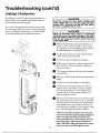
Leakage Checkpoints .................................................................................................................................................
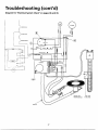
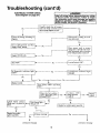
Thermostat and Gas Supply Check ...........................................................................................................................
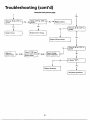
Electrical System Check ......................................................................................................................................
32
32
33-34
.33
33
33
33
34
.34
.35
36
37-39
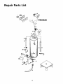
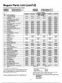
Repair Parts List ....................................................................................................................................
40-41
Warranty ..................................................................................................................
44
Customer Information
Thank
You
for purchasing a Maytag water heater.
Since we cannot put everything on the first few pages, READ
THE ENTIRE MANUAL BEFORE ATTEMPTING TO
INSTALL OR OPERATE THE WATER HEATER.
• The installation must conform with the instructions in this
Properly installed and maintained, it should give you years of
trouble free service. It is strongly suggested that this new water
heater be professionally installed, contact Maytag Customer
Service (1-800-788-8899) for recommended installers,
Abbreviations
Found In This Instruction
manual; gas company rules; and Local Codes, or in the
absence of Local Codes, with the latest edition of the
National Fuel Gas code, ANSI Z223.1, also referred to as
Manual
CSA - Canadian Standards Association
NFPA - National Fire Protection Association
ANSI - American National Standards Institute
NFPA 54. This publication is available from your local goveminent or public library or gas company or by writing
NFPA, Batterymarch Park, Quincy, MA 02269.
• After reading this manual you have any questions or do not
understand any portion of the instructions, call Maytag
Customer Service at 1-800-788-8899 for an authorized
servicer.
A WARNING
This gas-fired water heater is design certified by
CSA INTERNATIONAL
under American National
Standard/CSA Standard for Gas Water Heaters ANS
Z21.10.1 • CSA 4.1 (latest edition). The installation
must conform with this manual, Local Codes and
with the latest edition of the National Fuel Gas
Code,
ANSI Z223.1.
This publication
is available from your local govern-
• Carefiflly plan the place where you are going to put the water
heater. Correct combustion, vent action, and vent pipe installation are very important in preventing death from possible
carbon monoxide poisoning and tires.
ment or public library, gas company, or by writing
NFPA, Batterymarch Park, Quincy, MA 02269.
Examine the location to ensure the water heater complies with
the "Locating the New Water Heater" section in this manual.
• For California installation this water heater must be braced,
• Read the "Safety Instructions" section, pages 2, 3 and 4 of this
manual first and then the entire manual carefolly. If you don't
follow the safety rules, the water heater will not operate properly. It could cause DEATH, SERIOUS BODILY INJURY
AND/OR PROPERTY DAMAGE.
anchored, or strapped to avoid falling or moving during an
earthquake. See instructions for correct installation procedures. Instructions may be obtained from your local dealer,
wholesaler, public utilities or California Office of the State
Architect, 400 P Street, Sacramento, CA 95814.
• This manual contains instructons for the installation, operation. and maintenance of the gas-fired water heater. It also
• Massachusetts Code requires this water heater to be installed
in accordance with Massachusetts 248-CMR 2.00: State
contains warnings through out the manual that you must read
and be aware o£ All warnings and all instructions are essential
to the proper operation of the water heater and your safety,
Plumbing Code and 248-CMR 5.00.
• Complies with SCAQ.MD rule #1121 and districts having
equivalent NOx requirements.
Product Specifications
*Modal
HJ640NBDVT
HJ640PBDVT
HJ650NBDVT
HJ650PBDVT
Tank Capacity
In Gallons
40
40
50
50
75
75
Type of Gas
Natural
Propane
Natural
Propane
Natural
Propane
B.T.U. rate
40,000
36,000
40,000
38,000
70,000
65,000
41.0
37.0
41.0
39.0
72.0
66.0
3"
21"
3"
21"
3"
21"
3"
21"
3"
26%"
3"
261/,"
57"
57"
65V2"
651/2"
691/2"
Recovery Rate
In Gals Per Hr.
@90*FRise
Intake Air &
Exhaust
Vent Pipes
Diameter
Height To
Top of Blower
*High altitude models have a B.T.U./Recovery Rate 10% Iess than shown.
6
HJ675NRDVT HJ675PRDVT
J
691/2"
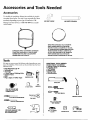
Accessoriesand Tools Needed
Accessories
To simplify the installation
Maytag
has available
the installa-
tion parts shown below. You may or may not need aU of these
(
ABS VENTELBOW
accessories depending on your type of installation. Call
Maytag Customer Service at 1-800-788-8899
for an authorized installer.
()
ABSVENTEXTENSION
DRAIN PANSAVAILABLEIN 22" DIAMETER
(PARTNUMBER66001011) FORWATER
HEATERSHAVING A DIAMETER20_ OR LESS,
24" DIAMETER(PARTNUMBER66001105) FOR
WATERHEATERSHAVING A DIAMETER22_
OR LESSAND AVAILABLEIN 28" DIAMETER
(PARTNUMBER 66001012) FORWATER
HEATERSHAVING A DIAMETER26" OR LESS
EXPANSIONTANKSFORTHERMAL EXPANSION
CONDITIONSAVAILABLEIN 2 GALLON(PART
NUMBER66001013) AND 5 GALLON(PART
NUMBER66001014) CAPACITY
Tools
ADDITIONAL
TOOLS NEEDED
WHEN SWEAT SOLDERING
• Tubing Cutters or Hacksaw
You may or may not need all of these tools, depending on your
type of installation. These tools can be purchased at your local
hardware store.
• Pipe Wrenches
• Screwdriver
(2) 14"
• 6 Foot Tape of Folding
• Garden Hose
• Drill
• Pipe
Propane
Torch
• Soft
Solder
• Solder Flux
Rule
dope or Teflon Tape
• Wire Brushes
GARDENHOSE
• Tin Snips
_
_
6 FOOTTAPE
• EmeryCIothHACKSAW
P,PE
WRENCH
ROLLOF TEFLONTAPE
(USEONLYON WATER
CONNECTIONS)
SLOT-HEADSCREWDRIVER
"7
3/4" WIRE BRUSH
1/2" WIRE BRUSH
PROPANETORCH
_
TIN SNIPS
PHILLIPSSCREWDRIVER
ROLLOF LEADFREE
SOFTSOLDER
PIPEDOPE(SQUEEZETUBE)
(USE FORWATERAND
GASCONNECTIONS)
ROLLOF EMERY
CLOTH
7
SOLDERFLUX
TUBINGCUTTER
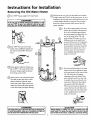
Instructions for Installation
Removing
the Old Water Heater
Turn "OFF" the gas supply to the water heater.
@
_, WARNING
Disconnect the vent pipe from the draft hood or blower
assembly where they connect to the water heater. In most
]
instaUations
or
other attached
the vent
devices
pipe are
canremoved.
be lifted The
off after
new any
water
screw
If the main gas line shutoffservingall gasappliancesis used,
I
also shut "OFF",thegas at eachappliance,Leaveall gasappli-|
ancesshut"OFF unt_ thewater heaterinstallationiscomplete.I
heater has a blower assembly which must be used for
proper operation.
a. If you have copper piping to the water
heater, the two copper water pipes can
cutw
ka
po
four inches away from where they connect to the water heater. This will
@
@
@
@
Turn "OFF" the water to the water
heater. Some installations require that
the water heater is drained, disconnect
the hose from the drain valve. Close
the drain valve. The water heater is
the water be turned offto the entire
house.
avoid cutting offthe pipes too short.
Additional cuts can be made later if
necessary. Disconnect the temperaturepressure relief valve drain line. When
now completely disconnected and
@
ready to be removed.
Check again to make sure the gas supply is "OFF" to the water heater. Then
disconnect the gas supply connection
@
from the gas control valve,
Attach a hose to the water heater drain
b. If you have galvanized pipe to the water
heater, loosen the two galvanized pipes
with a pipe wrench at the union in each
line. Also disconnect the piping
remaining
to the
water since
heater.they
These
pieces
should
be saved
may
be needed when reconnecting the new
water heater. Disconnect the temperature-pressure refiefvalve drain line.
When the water heater is drained, disconnect the hose from the drain valve.
Close the drain valve. The water heater
valve and put the other end in a floor
drain or outdoors. Open the water
heater drain valve. Open a nearby hot
water faucet which will relieve pressure
in the water heater and speed draining,
_._
readyiS
nowandto
completely
be removed.
disconnected
AWARNING
I
ACAUTION
Thewater passingout of the drainvalvemaybe extremelyhot.
Toavoidbeingscalded,makesureall connections
are tight and I
thatthe waterflow isdirectedawayfrom anyperson.
Mineralbuildupor sedimentmay have accumulatedin the old
water heater.Thiscausesthe water heater to be muchheavier
I
than normalandthis residue,if spilledout,couldcausestaining.
8
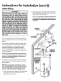
Instructions for Installation (cont'd)
TYPICAL INSTALLATION
INTAKE FOR
COMBUSTION
AIR
Vacuum Relief required
' some codes
EXHAUST
VENT TO
OUTDOORS
DISCHARGE PIPE
HOT WATER OUTLET
TEMPERED
WATER OUTLET
\\_
/
_
_\_
_\_
TEMPERATUREPRESSURE
RELIEF VALVE
MIXING
VALVE
\\_
_\_
_\_
_
:
GAS
SUPPLY
_
DISCHARGE PIPE
(Do not cap or plug)
PROVIDE A 6" AIR GAP
BETWEEN THE END OF
THE DISCHARGE PIPE
AND DRAIN
This appliance has been design certified as complying with American National Standard/CSA
considered suitable for:
Water (Potable) Heating: AU models are "considered suitable for water (potable) heating."
Standard for wate_ heaters and is
AWARNING
When the system requires water at temperatures
higher than requiredfor other uses, the hot water
system may require a means such as a mixing valve
to be installed to temper the water at certain
points of use. Somepeople
are more likely to be I
AWARNING
This water heater shall not be connected to any
heating systems or component(s) previously used
with a non-potable water heating appliance.
permanently
injuredby
hot water than others; I
these include the elderly, children, the infirm, or I
the physically/mentally
handicapped.
Before
immersing yourself or anyone else in hot water, be
sure
to check
theINCREASES
water temperature.
HOTTER
WATER
THE RISK WARNING:
OF SCALD
INJURY. (Also see "Temperature Regulation" section) Mixing valves are available at plumbing supply or hardware stores, Follow manufacturers
instructions for installation of these valves,
AWARNING
Toxic chemicals such as used for treatment of boilers or non-potable water heating appliances shall
never be introduced into a potable water space
heating system.
NOTE: To protect against untimely corrosion of hot and
cold water fittings, it is strongly recommended that dielectric unions or couplings be installed on this water
heater when connected to copper pipe.
9
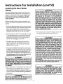
Instructions for Installation (cont'd)
Locating the New Water
Heater
ACAUTION
WATER HEATERS EVENTUALLY LEAK: Installation of
the water heater must be accomplished in such a
manner that if the tank or any connections should
leak, the flow of water will not cause damage to
the structure. For this reason, it is not advisable to
install the water heater in an attic or upper floor.
When such locations cannot be avoided, a suitable
drain pan should be installed under the water
heater. Drain pans are available at your local hardware store. Such a drain pan must have a minimum
length and width of at least 2 inches greater than
the water heater dimensions and must be piped to ]
an adequate drain.Drain pan depth must allow I
access to the outer doors for servicing the ignitor
and burner. Under no circumstances is the manufac-
You should carefiaUychoose an indoor location for the new
water heater, bceansethe placement is a very important consideration for the safety of the occupantsin the building and
for the most economicaluse of the appliance. Thiswater
heater is not for use in manufactured (mobile)homes or
outdoor installation.
Whether replacing an old water heater or putting the water
heater in a new location, the following critical points must be
observed,
• The location selected should be indoors as close as practical to
piping
as possible.
heater, aswith
all water
the ventsystem
termination
point,The
andwater
as centra/ized
the water
heaters, wiU eventually leak. Do not install without adequate
nectionto with
this liable
water forheater.
turer
be held
any water damage
drainage provisions where water flow will cause damage.
• The location selection must provide adequate clearances for
• If vented through an outside wall or through the roof using
3" vent piping, the total vent run (vertical and horizontal)
cannot exceed 45 feet with one elbow. If more elbows are
n con-
servicing and proper operation of the water heater.
A WARNING
iNSTALLATIONS IN AREAS WHERE FLAMMABLE LIQUIDS (VAPORS) ARE LIKELY TO BE PRESENT OR
STORED (GARAGES, STORAGE, AND UTILITY AREAS,
ETC): Flammable liquids (such as gasoline, solvents,
propane (LP) or butane, etc.), all of which emit
flammable vapors, may be improperly stored or
used in such areas. The gas water heater ignitor or
main burner can ignite such vapors. The resulting
flashback and fire can cause death or serious burns
to anyone in the area, as well as property damage.
If installation
in such areas is your only option, I
then the installation must be accomplished in a [
way that the ignitor and main burner flame are ele- I
vated from the floor at least 18 inches. While this
may reduce the chances of flammable vapors from
a
floor spill substances
being ignited,gasoline
otheror
flammable
shouldnever
beand
stored
required, the venting distance must be reduced 5 feet for
every 90 ° elbow. See page 19 for vent chart,
• Vent piping cannot slope downward and horizontal runs
require 1/,,, per five foot rise. ALlhorizontal runs require
adequate support at 3'/2 foot intervals and vertical runs
supported at 5 foot intervals,
• The water heater requires its own (separate)venting system,
It cannot be connected to an existing vent pipe or chimney. It
must terminate to the outdoors. Whenever possibleterminate
the vent on the leeward side of the building through an outside wall. NOTE: Condensation maybe created, at times, as
the combustiongasesexit the vent cap anddiscoloration of
surfacesinproximitytotheventcapmayoccur,
used in the same room or area containing agas
water heater or other open flame or spark producing appliance.
NOTE: Flammable vapors may be drawn by air currents
from other areas of the structure to the appliance.
AWARNING
The power direct vent water heater requires its own
(separate) venting system. R cannot be connected to an
existing vent pipe or chimney. It must be terminated to
the outdoors. Failure to properly install the venting system can result in asphyxiation, a fire or explosion and
can cause DEATH, SERIOUSBODILY INJURY,OR PROPERTY DAMAGE.
AWARNING
Propellants of aerosol sprays and volatile compounds, (cleaners, chlorine based chemicals, refrigerants, etc.) in addition to being highly flammable
in many cases, will also change to corrosive
hydrochloric acid when exposed to the combustion
products of the water heater. The results can be
hazardous, and also cause product failure.
e The water heater comesequipped with a 7 foot power cord
which can be used to connect to a 110/120 volt power
source if(l) local codes allow, and (2) there is a three prong
receptacle available, This unit must have a grounded outlet to operate,
AWARNING
I
Do not use an extension cord. If there is not a suitable receptacle and/or local codes prohibit use of a
power cord, f e d wiring must be prov ded.
10
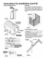
Instructions for Installation (cont'd)
Locating the New Water
Combustion Air and Exhaust
Heater (cont'd)
Whon determining the installation location for a power direct
vent water heater, snow accumulation and drifting should be
considered in areas where applicable.
_WARNING
This water heater must not be installed directly on
carpeting. Carpeting must be protected by a metal
or wood panel beneath the appliance extending
beyond the full width and depth of the appliance
by at least 3 inches (76.2mm) in any direction, or if
the appliance is installed in an alcove or closet, the
entire floor must be covered by the panel. Failure
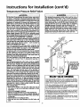
VENTINGCLEARANCES
Venting Through an Outside Wall- Clearances
" 0" ciearance for 3" PVC, ABS or CPVC Schedule 40 vent
piping from combustible surfaces.
to heed this warning may result in a fire hazard.
_,WARNING
• 18" minimum in all directions from any obstruction that may
interfere.
1
* 12" minimum from the ground, 9" ceiling overhangs.
Figure 2, page 12.
J
Minimum clearanc_e
water heater and [
combustible construction are 0" at the sides and rear, |
6" at the front to closet door, and 0" from the vent I
pipe. Clearance from the top of the jacket is 14".
j
• The Power Direct Vent outlet terminal shall terminate at least
36" above any forced air inlet located within I0 feet. Figure 3,
page 12.
• The Power Direct Vent outlet terminal of 40,000 Btuh orless
models shall terminate at least 9" below, 9" horizontally from or
v
_
FRONTViEW
• The Power Direct Vent outlet terminal of 65,000 and 70,000
9" above any door, window or gravity air inlet into the building.
Btuh models,,shall terminate at.....
least 12" below, 12" horizontally
Figureor3,12page
from
above
12. any door, window or gravaty lur inlet into the
building. Figure 3, page 12.
_0.M[]
_.i,:
vo,v,_w"
'o..,..
WITHOUTDOOR
orctosrr _' OF
"COPVIEW
CLOSET
wIT.ooo.
OFooo,
" 18" minimum from other natural draft (gravity) direct vent,
power
power
vent or
direct vent appfiance inlet and/or outlet
vent(s) when directly above or 135° to either side of center
line. Figure 4, page 12.
Figure 1 ]J
Air for ventilation should be provided if installed in a confined
space. Refer to the National Fuel Gas Code, ANSI Z223.1.
* 24" minimum from any appliance inlet and/or outlet vents
when directly below or 45° to either side of center line. Figure
4, page 12.
AWARNING
Do not install in a confined area such a closet, unless
you provide ventilation air as shown in Figure 1.
Never obstruct the flow of ventilation air. If you
have any doubts or questions at all, call your gas
company. Failure to provide ventilation
air can result
in a fire or explosion and can cause DEATH, SERIOUS
BODILY INJURY, OR PROPERTYDAMAGE.
• 18" minimum in all directions from any obstruction that may
interfere. Figure 3, page 12.
• The location selection must provide clearances for servicing
and proper operation of the water heater. Figure 5, page 12.
,, Vent termination must not be within 4 feet of any items such
as gas meters, gas valves or other gas regulating equipment.
• The venting system must be installed in a manner which
allows inspection of the installation of the venting pipes and
joints as well as periodic inspection after installation as
required by ANSI Standards.
il WARNING
If this water heater will be used in beauty shops,
barber shops, cleaning establishments, or self-ser-
_,WARNING
vice laundries with dry cleaning equipment, it is
imperative that the water heater or water heaters
be installed so that combustion and ventilation
air
be taken from
outside
areas.section
Refer of
to this
the
"Locating
the New
Waterthese
Heater"
manual and also the latest edition of the National
Vent termination
must not be within 4 feet of any
items such as gas meters, gas valves or other gas regu ating equipment.
AWARNING
Fuel Gas Code, ANSI Z223.1, also referred to as NFPA
54 for specifics provided concerning air required.
Failure to have required clearances between water
heater and combustible material will result in a fire
hazard.
11
I
Instructions for Installation
VENTINGCLEARANCES
(CONT'D)
-_
WIRE FENCE
touched accidentally, or is accessible to small children, a wire
mesh chain rink fence (as shown in Figure 6) may be used.
When
the water
heater to outlet
terminal
is lowventilation
enough toaround
be
Care should
be taken
maintain
adequate
the outlet terminal. Ifa chain link fence is installed, it must
"%"_,
9" min. from
any overhang
_
(cont'd)
_.of Flue
not be used as a storage area for items that may block proper
ventilation.
12" min.
as a storage area
I---"7
Not to be used
4'
A - 9" min. 140,000 BtuH
input models or less)
A - 12" min, (over 65,000
_
/
BtuH input models)
-B-
TE
LESSTHAN120°
FORCEDAIR
INLET
CORNER
INSTALLATION
OFINLETANDOUTLET
NOTRECOMMENDED
VENTOUTLET
• 0" clearance for 3" PVC, ABS, or CPVC Schedule 40 piping from
combustible surfaces.
• The Vent Exhaust outlet and air irdet terminals shall terminate at
least 18 inches above the roof surface. Figure 7.
• The location selection must provide clearances for servicing and
proper operation of the water heater. Figure 5.
• The venting system must be installed in a manner which allows
inspection of the installation of the venting pipes and joints as
well as periodic inspection after installation as required by
CAN/CGA
Standards.
45° VENT CAP.
W/SCREEN _
I 4s" . /
DIRECT VENT,
_"_
OR POWERDIRECTVENT
APPLIANCE
INLET AND/OR
............
on* CTO==Tm I
--
(_RAVITY)
VENT,
POWER
OUTLETVENT(S).
[ Figure 4 ]
Must maintain
adequate service_
and maintenance
accessibility,
,
ii! ,
:_"_-_/
\"
[ Figure 5 ]
",
!__
::il_
/
/"'_""_
//"
.....................
/
Ranaeofdegrees
avaiTab,e
I
I Figure7
I
for vent
pipe installation.
12
I
I
I
_
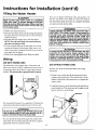
Instructions for Installation (cont'd)
Water
Piping
AWARNING
2. Look at the top cover of the water heater. The cold water
HOTTER WATER CAN SCALD: Water heaters are
intended to produce hot water. Water heated to a
temperature
which will satisfy clothes washing,
dish washing, and other sanitizing needs can scald
md permanently injure you upon contact. Some
people are more likely to be permanently injured by
lot water than others. These include the elderI.y,
children, the infirm, or physically/mentally
handlcapped. If anyone using hot water in your home fits
into one of these groups or if there is a local code or
state law requiring a certain temperature water at
the hot water tap, then you must take special erecautions. In addition to using the lowest possible
temperature setting that satisfies your hot water
needs, a means such as a mixing valve, should be
used at the hot water taps used by these people or
at the water heater. Mixing valves are available at
plumbing supply or hardware stores. Follow manufacturers instructions for installation of the valves.
Before changing the factory setting on the thermostat, read the "Temperature Regulation" section in
this manual.
inlet is marked cold. Connect the cold water pipe to the
cold water inlet of the water heater.
NOTE: Thiswater heater is insulated to minimize heat
loss from the tank. Further reduction in heat loss can be
accompllshedby insulating the hot water ]ines from the
water heater.
INTAKEFOR
COMBUSTION
AIR
EXHAUST
VENT
TOOUTDOORS
This water heater shall not be connected to any heating sysINTAKE
SHUTOFF PiPE
VALVE
COLDINLET
WATER
LINE
tems or component(s) used with a non-potable water heating
appliance.
If a water heater is installed in a closed water supply system;
such as one having a back-flow preventer, check valve, water
meter with a check valve, etc.., in the cold water supply;
means shall be provided to control thermal expansion.
/_
,%\
_\ _
_\_ FLUEPRODUCTS
_\_ DISCHARGE
PIPE
_',s
\x
_\_
Contact the local utility or call Maytag Customer Service
Center at 1-800-788-8899 for an authorized installer on how
to control this situation.
NOTE: To protect against untimely corrosion of hot and
cold water fittings, it is strongly recommended that di-electric unions or couplings be installed on this water heater
when connected to copper pipe.
TEMPERATUREPRESSURE
RELIEF
VALVE
_\ _
_\_\\ HOTTo
HOusEOUTLET
_\ _
_\ _ DISCHARGE
PIPE
_\_ :Donotcaporplug)
_\_ C_AP
PROVIDE
A6"AIR
BETWEEN
11'1E
ENDOFTHE
_\\ _ DISCHARGE
PIPE
_\_
ANDDRAJN
_\_
GAS
The illustration shows the attachment of the water piping to
the water heater. The water heater is equipped with 3/4 inch
water connections.
k\'_
NOTE: If using copper tubing, solder tubing to an adapter
_\ x
Do not solder the cold water supply line directly to the cold
water inlet. It will harm the dip tube and damage the tank.
1. Look at the top cover of the water heater. The water outlet
is marked hot. Connect the hot water pipe to the hot
water outlet on the water heater.
13
SUPPLY
i
Instructions for Installation (cont'd)
Temperature-Pressure
Relief Valve
WARNING
A WARNING
At the time of manufacture this water heater was provided with a combination tempereture-pressures relief valve
certified by a nationally recognized testing laboratory that
maintains periodic inspection of production of listed
equipment or materials, as meeting the requirementsfor
Relief Valves and Automatic Gas Shutoff Devices for Hot
Water Supply Systems, and the latest edition of ANSI
Z21.22 and the code requirements of ASME. If replaced,
the valve must meet the requirements of local codes,but
not less than a combination temperature and pressure
relief valve certified as meeting the requirements for
Relief Valves and Automatic Gas Shutoff Devicesfor Hot
Water Supply Systems,ANSI Z21.22 by a nationally recognized testing laboratory that maintains periodic inspection
of production of listedequipment or materials.
The valve must be marked with a maximum set pressure
not to exceedthe marked hydrostaticworking pressureof
the water heater (150 Ibs./sq. in.) and a dischargecapacity
not lessthan the water heater input rate as shown on the
model rating plate. (Electric heaters - watts divided by
1000 x 3415 ec_ualBTU/Hr.rate.)
Your local jurisdictional authority, while mandating the!
use of a temperature-pressurerelief valve complying with
ANSI Z21.22 and ASME, may require a valve model different from the one furnished with the water heater.
Compliancewith such local requirementsmust be satisfied
by the installer or end user of the water heater with a
Iocallyprescribed temperature-pressure relief valve
installed in the designated opening in the water heater in
The temperature-pressure relief valve must be manually operated at least once a year. Caution should be
taken to ensure that (1) no one is in front of or
around the outlet of the temperature-pressure relief
valve discharge line, and (2) the water manually discharged will not cause any bodily injury or property
damage because the water may be extremely hot.
If after manually operating the valve, it fails to cornpletely reset and continues to release water, immediately close the cold water inlet to the water heater,
follow the draining instructions, and replace the
temperature-pressure relief valve with a new one.
COLD
TEMPERATUREPRESSUREvALvERELIEF
place
of the
factory furnishedvalve.
For safe
operation
of the water heater, the relief valve I
must not be removed from it's designated opening or
plugged.
The temperature-pressure relief valve must be installed
directly into the fitting of the water heater designatedfor
I the relief valve. Positionthe valve downward and provide
tubing so that any dischargewill exit only within 6 inches
above, or at any distance below the structural floor. Be I
certain that no contact is made with any live electrical
part. The discharge opening must not be blocked or
reducedin size under any circumstances.Excessivelength,
over 30 feet, or use of more than four elbows can cause
restriction and reducethe dischargecapacity of the valve.
No valve or other obstruction is to be pieced between the
relief valve and the tank. Do not connecttubing directly to
dischargedrain unlessa 6" air gap is provided. To prevent
bodily injury, hazard to life, or property damage, the relief '
valve must be allowed to discharge water in quantities
should circumstancesdemand. If the dischargepipe is not
connected to a drain or other suitable means, the water
flow may causeproperty damage.
The DischargePipe:
Must notbe smaller in size than the outlet pipe size of
the valve, or have any reducing couplings or other
restrictions.
Must not be plugged or blocked.
Must be of material listedfor hot water distribution.
Must be installed so as to allow complete drainage of
both the temperature-pressurerelief valve, and the discharge pipe.
Must terminate at an adequate drain.
Must not have any valve between the relief valve and
tank,
TEMPERED
WATER
OUTLET
(Do
not capor
PROVIDE
A 6"plug)
AIR
GAPBEI_NEEN
THE
ENDOFTHE
DISCHARGE
PIPE
AND DRAIN
RELIEF
VALVE
OPENING
'THISWATER
HEATER
ISPROVIDED
WITHA COMBINATION
TEMPERATURE-PRESSURE
RELIEF
VALVE.
FORSAFEOPERATION
OFTHEWATER
HEATER,
THERELIEF
VALVE(S)
MUSTNOTBEREMOVED
FROMITSDESIGNATED
PDINTOF
INSTALLATION
ORPLUGGED."
YOURLOCAL
JURISDICTIONAL
AUTHORITy,
WH_LE
MANDATING
THEUSE
OFA TEMPERATURE-PRESSURE
RELIEF
VALVE
COMPLYING
WITHANSI
z21.22ANDASME,MAYREQUIRE
A VALVE
MODELDIFFERENT
FROM
THEONEFURNISHED
WITHTHEWATER
HEATER.
COMPLIANCE
WITHSUCHLOCAL
REQUIREMENTS
MUSTBESATISFIED
BYTHEINSTALLER
ORENDUSEROFTHEWATER
HEATER
WITHLOCALLYPRESCRIBED
TEMPERATURE-PRESSURE
RELIEF
VALVE
INSTALLED
IN
THEDESIGNATED
OPENING
INTHEWATER
HEATER.
SEEMANUAL
HEADING--"TEMPERATURE-PRESSURE
RELIEF
VALVES'
FORINSTALLATION
ANDMAINTENANCE
OFRELIEF
VALVE.
DISCHARGE
LINEANDOTHER
SAFETY
PRECAUTIONS.
14
Instructions for Installation (cont'd)
Filling the Water Heater
ACAUTION
If you are not familiar with electric codes and practices, or if
Neverusethis water heaterunlessit is completelyI
filled with water. Toprevent damage to the tank,
you haveany doubt in your abilityto connectthe wiring to
this waterheater,obtainthe serviceof a competentelectrician
the tank must be filledwith water. Water must flow I
from the hot water faucet before turning "ON" gas
to the water heater.
or contact your local electric utility.
AWARNING
To fill the water heater with water:
WATER HEATERS EQUIPPED FOR ONE TYPE VOLT-
" Close the water heater drain valve by turning the handle to
AGE ONLY: This water heater is equipped
for
110/120 volts only. DO NOT USE THIS WATER
HEATER WITH ANY VOLTAGE OTHER THAN THE
ONE SHOWN ABOVE. Failure to use the correct voltage can cause problems which can result in DEATH,
SERIOUS BODILY INJURY OR PROPERTY DAMAG E. If
you have nay questions
or doubts consult your
electric company.
the right (clockwise). The drain valve is on the lower front
of the water heater.
, Open the cold water supply valve to the water heater,
NOTE: The cold water supply valve must he left open
when the water heater is in use.
• To insure complete filling of the tank, allow air to exit by
opening the nearest hot water faucet. Allow water to run
until a constant flow is obtained. This will let air out of the
_ CAUTION
water heater and the piping,
• Check all new water piping for leaks. Repair as needed,
If wiring from the fuse box or circuit breaker box was
aluminum for the old water heater, replace it with
copper wire. If you wish to reuse the existing aluminum wire, have the connection at the water heater
W iring
trical
and/or electrician.
the local electric
utility.
made contractor
by a competent
Contact
a local elec-
_
USE WITH POWER CORD
The water heater comes equipped with a 7 foot power cord
USE WITHOUT
POWER
CORD
which can be used to connect to a 110/120 volt power source if,
(1) local codes allow, and (2) there is a three prong receptacle
available. This unit must have a grounded outlet to operate.
If power cord cannot be used, then follow these wiring
instructions.
1. Provide a way to easily shut offthe electric power when
working on the water heater. This could be with a circuit
breaker or fuse block in the entrance box or a separate dis-
2. Install and connect a circuit directly from the main fuse or
circuit breaker box. This circuit must be the right size and
have its own fuse or circuit breaker.
i
connect switch.
j//WIRE
NUTS
You must provide all wiring, (1) to a receptacle or, (2) between the
water heater and junction box when the power cord is not used.
AWARNING
I Do not use an ext_there
is not a suitable receptacle and/or local codes prohibit use of a
CONDUIT
[ power cord, field wiring must be provided.
GREEN
GROUNDSCREW
You must provide all wiring of the proper size outside of the
water heater. You must obey local codes and electric company
requirements when yon install this wiring.
15
,,
Instructions for Installation (cont'd)
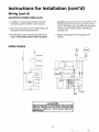
Wiring
(cont'd)
USE WITHOUT POWER CORD (cont'd)
3. A standard 1/2"conduit opening has been made in the
water heater junction box for the conduit connection,
grounded. A green ground screw has been provided on the
water heaters junction box. Connect ground wire to this
location. For complete grounding details and all allowable
exceptions, refer to the latest edition of the National
Electrical Code.
4. Use wire nuts and connect the power supply wiring to the
wires inside the water heaters junction box.
5. The water heater must be electrically "grounded" by the
installer. The unit will not operate unless it is properly
6. Replace the wiring junction cover using the screw
provided.
WIRING DIAGRAM
&CAUTION
Label all wires prio_ction
when servicing
controls, wiring errors can cause improper and
dangerous operation.
Verify proper operation
after servicing.
16
Instructions for Installation (cont'd)
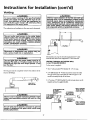
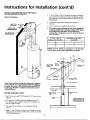
Venting
AWARNING
To insure proper venting of this gas-fired water
heater, the correct vent pipe diameter must be utilized. Any additions of other gas appliances on
vent with this water heater will adversely affect
the operation of the water heater,
_WARNING
Chemicalvapor corrosionof the flue and vent systam may occurif air for combustioncontainscertain
chemicalvapors. Spray can propellants, cleaning solvents, refrigerator and air conditioner refrigerants,
swimming pool chemicals,calciumand sodium chloride, waxes, bleach, and processchemicalsare typical compoundswhich are potentially corrosive.
The combustionand ventilation airflowmust not be obstructed.
AWARNING
The vent outlet must connect to the water heater
exhaust outlet. The vent inlet piping must connect
to the water heater air inlet. Both the water heater
instruction can result in DEATH, SERIOUSBODILY
INJURY,OR PROPERTYDAMAGE.
connections are clearly marked. Failure to read this
_ll_
L--
;I
II
STRAPPING
Obstructed or deteriorated vent systems may present a serious health risk or asphyxiation.
&WARNING
]
A WARNING
I
I
Horizontal
mustruns
be securely
3'/2 foot
intervals
andruns
vertical
supportedsupported
at 5 foot at
intervals.
The vent pipe from the water heater must be 3,"
diameter PVC(ABSon 75 Gallon modelsfor first 5 ) I
Schedule 40 pipe and must slope upward ¼ inch
per five feet.
VENTINGTHROUGHAN OUTSIDEWALL
A. ALL75 GALLONMODELS
In the carton is supplied:
• Two3" inletandoutlet PVC Schedule40 - 45°ventcaps.
All vent gases must be completelyvented to the outdoors of the
structure (dwelling).
I
• A 3" ABSSchedule40 - 90streetell;usedto connectthe outlet
ventpipeto the waterheaterwhenthe outletventpipeis to be
turned horizontallydirectlyoffthe blower.
[_
requiredandmustbe suppfiedlocally).
_0
• A 5"sectionof Y'ABS Schedule40outletventpipe(moremaybe
3" ABS SCHEDULE 40
90 ° STREET
OUTLET ELBOW
SUPPUED
]
_, WARNING
3" PVCSCHEDULE
Failure to have required clearances between water
heater and combustible material will result in a fire
PIPE
SUPPLIED
,._,_..-_
4090°STREET
I l/
INLET
ELBOW If I'_
REQUIRED
S" SCHEDULE
40 ABS OUTLET
_
_I I
40 PVC45° INLET
ELBOW
SUPPLIED
ONE
3" SCHEDULE
/
/
[
]
_-_
40 PVC INLET PIPE
hazard.
[_L_
SCHEDULE ONE 3" SCHEDULE
REQUIRED
& WARNING
ELBOW
SUPPLIED
Be sure vent pipe is properly connected to prevent
escape of dangerous flue gases which could cause
deadly asphyxiat on.
_--7
17
40 PVC45 ° OUTLET
Instructions for Installation (cont'd)
Venting
(cont'd)
VENTING SYSTEM EXAMPLE INSTALLATIONS FOR ALL
MODELS
1. The water heater requires its own (separate) venting
system.
The vent piping cannot under any circumstances be run
downhill.
2. O_ly3"ABS Schedale 4Opiping and fittlngs are acceptable
materials on the first five feet oft.he outlet vent system.
3. 3" PCV, fiBS, or CPVC Schedule 40 piping and fittings are
acceptable materials for the inlet vent system and for the outlet
vent system after the first five feet.
4. It cannot be cormected to existing vent piping or
chimne_
I[_
5. When venting through an outside wall, the vents must terminate
horizontally to the outdoors.
B. ALL 40 AND 50 GALLON MODELS
The vent piping can be installed as follows:
In the carton is supplied:
1. Horizontal runs require a minimum %" rise per five feet.
• Two 3" inlet and outlet PVC Schedule 40 - 45 ° vent caps,
3 ELBOW
All other piping must be supplied by the supplier.
TWO3" PVCSCHEDULE
40 90*STREET_ _
ELBOWfr.LI
REQUIRED*
EXAMPLE_
/I \\
/ I \\
ONE 3"SCHEDULE
40PVC45° INLET
ELBOWSUPPLIED
I
I I I I
I I I I
MIN.RISEY."
PERFIVEFEET
I
40 PVCPIPE
SCHEDULE
REQUIRED
ONE3" SCHEDULE
40 FVC45° OUTLET
ELBOWSUPPLIED
• If malting an immediate horizontal run of vent off the
blower, two 3" PVC or ABS Schedule 40 street elbows are
required
1. The water heater requires its own (separate)venting
I|
3 ELBOW
MIN.RISE'/*"
PERFIVEFEET
2. 3" PVC, ABS, or CPVC Schedule 40 piping and fittings
are acceptable materials for the vent system on all 40 and
50
system.
gallon models.
EXAMPLE
__l_
3. It cannot be connected to existing vent piping or
chimney,
I
4. When venting through an outside wall, the vents must terminate horizontally to the outdoors.
18
II
_l
Instructions for Installation (cont'd)
Venting (cont'd)
3 ELBOW
EXAMPLE
CAULK
JOINT_
_r_"_l
_
__
_
!
Cementing PVC, ABS OR CPVC Pipe and Fittings
Read and observe all safet_ information printed on primer,
I1_
[
_AADANGER
|Primer,
cleaner,
and cements are extremely
cleaner' and cement
I The vapors are harmful. They may irritate eyes and
/flammable. They are harmful or fatal if swallowed.
[ skin and can be absorbed through the skin.
cOntaIners'PER
MIN"
FIVEFEET
RIsE¼"
t
I_-./_]_M_R
_T_I
I
_
ISE'/,"
PERFIVE
FEET
I
& PRECAUTIONS
Always store primers, cleaner, and cements in cool,
dry, well ventilated places. Do not store them near
heat, sparks, or flames. Keep containers closed. Use
them in well ventilated
areas. Wear impervious
clothing while handling. Do not smoke, eat, or drink
while handling. Wash thoroughly after handling
and before eating. Wear eye protection when handling. If swallowed, drink water, do not induce vomiting, and call a physician or poison control center
immediately. If inhaled, get fresh air and seek medical attention if ill feelings persist. In case of eye and
skin contact, immediately flush with plenty of water
for 15 minutes and seek medical attention if irritation persists. KEEPOUT OF REACH OF CHILDREN.
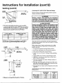
2. The total vertical and horizontal run cannot exceedthe
maximum lengthwith the number ofg0* elbowsasspedfied
in the table below.Ifmure elbowsare requlred,the venting
distancemust be reduced5 feet for every 90*elbow:
3" DIA. VENTS
MAX. LENGTH (FT.)
NUMBER OF 90 ° DEG.
ELBOWS*
45
40
35
1
2
3
*NOTE: Two 45 ° elbows are equivalent to one 90" elbow.
One 90 °elbow equals 5 feet of equivalent vent length,
1 ELBOW
EXAMPLE
Before using primers, cleaners, and cements, stir or shake,
making sure contents are fiquid. Do not use if found to be
lumpy or jelly-fike.
45"
16" MAX.
MIN,
<
t
13¼" M
All primers, cleaners, and cements must meet all local codes
and applicable standards of the American Society For Testing
Materials Standards.
f
11¼" MIN.
[_
2. Dry fit pipe and fittings to be connected for proper fit.
MIN. RISE V."
PER FIVE FEET
3. Clean
pipe
and fitting
with
a primer/cleaner.
4. Apply a thin coat of cement to fitting, avoiding puddling
inside.
5. Apply a liberal coat of cement to pipe leaving no voids.
1. Cut pipe ends squarely removing all burrs and dirt.
6. QUICKLY assemble parts while cement is fluid! If you
wait too long, re-coat pipes.
__
1 ECSOW
I
j_
EXAMPLE
--_--
_r[ f-A J]_.
[ \
"[.
|
'1
-1
38' _1
7. Push pipe completely into socket of fitting, turning as it
goes until it bottoms.
II1_
8. Hold
pipe and
fittingwitha
together
for Allow
30 seconds.
Then carefully clean
off excess
cloth.
connections
a sufficient time to cure before disturbing.
MIN. RISE ¼-
9. Remember that vent pipes must be adequately and securely
\"_x_R FOOT
o
APPROXIMATE
PIPE JOINTS
90°F to 150OF
50°F to 90°F
3. Minimum vent length for all models is 18 inches.
0 ° Fto SO*F
19
SETTING
TIME
FOR 2%" TO 4"
OF JOINT
¾ hr.
MOVEMENT
1 hr.
SET
8
hrs.
COMPLETE
15 hrs.
1½ h r.
18 hrs.
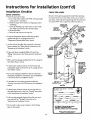
Instructions for Installation (cont'd)
Venting
(cont'd)
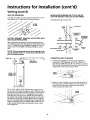
VENT PIPE SEPARATION
INSTALLATION SHOWING USE OF PVC, ABS OR
CPVC PIPE FOR INLET AND OUTLET VENT PIPING:
The inlet and outlet vent pipes must be separated by a minimum distance of 6% inches up to 24 inches maximum.
Inlet piping through any type wall.
.._
AND COLLAR INSTALLATION
CUTTING OPENINGS THROUGH AN OUTSIDE WALL
After reading the manual and you have determined the locafion of the opening in the wall, (using the drawing below), cut
screw
1
FLUE MOUNTING
ADAPTER
°
SCREW
/ II
[
_._
/_
VENT CAP MUST
---
AM
--_[/IU_
_- _
screw......
wall.
EXTERIOR WALL
[
nv
one
31/2"diameter
holeoudet
for the
vent through
pipin_and
one 31/2"
diameter
hole for the
ventinlet
piping
an exterior
_
/
_
"*
_FLUE ADAPTER
MOUI_mNG
OUTLET
EEN AT
outside wall allow for the V¢"rise per five feet that has taken
place in the horizontal run.
C£OF FLUE .... _ ......
1VA" MIN.
_
F_
....
_'H
I
--T_
MIN. RISEY,"
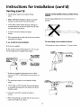
CONNECTING
VENT
TO
BLOWER
1. If making an immediate horizontal run of vent offthe
blower, one 3" PVC inlet and one 3" PVC (ABS for 75
PERFIVEFEET
Place the elbow in the required direction on the blower and
using 3 sheet metal screws, attach the elbow.
T
Gal. Models) outlet Schedule 40 street elbows are required.
CAULK
40
50 GAL.GAL.- 48'½"
57½_
-_-_-.
.i_"
JOINTS "---__.._
7S GAL.-63"
['---1
_-_'_'_-5_'_l
'
'l
_.__._._
] I_.
_-_
'_
2. If there is to be a vertical run of vent from the blower, the 3"
PVC inlet and the 3" PVC (ABS for 75 Gal. Models) outlet pipes must be attached to the blower and venting
hood, using 6 sheet metal screws.
,
The 3" PVC, ABS or CPVC Schedule 40 vent plpe can be
run from the water heater through the wall or from the wall to
the water heater, whichever is most convenient. The vent pipe
must extend a minimum ofl/2
through the exterior waU.
Extending the vent cap as far as l_ossible from the surface of
the exterior wall will help minimtze discoloration of the wall.
CAULK
JOINTS
"--'__-....
"_"---_.
" '-_ J"
over the vent piping before locating the-pipe through the wall.
Note that
Before
securing
the inside
the inside
flue mounting
and outside
adapters
collarsmust
to the
be wall,
slipped
use
a silicone sealer between pipe and opening to insure a water
and air tight seal.
.I
-J
_"
J
*'-//
20
"_
_" I
I
_
--..1_
_ _']
I
"_"
Instructions for Installation (cont'd)
INSTALLATION SHOWING USE OF (OPTIONAL)
DELUXE HORIZONTAL VENT KIT:
3. 3" PVC, ABS, or CPVC Schedule 40 piping and fittings
are acceptable materials for the inlet vent system and for
the outlet vent system (after the first five feet for 75 Gal.
Models only).
Typical installation,
AIRINTAKE
4. It cannot be connected to existing vent piping or
chimney.
5. It must terminate vertically to the outdoors.
6. The total vertical and horizontal run cannot exceedthe
maximum length with a maximum number of 90" elbows
as specified in the table below. If more elbows are
required, the venting distance must be reduced 5 feet for
every 90° elbow.
VENT TO _
OUTDOORS
INTAKE
FOR
COMBUSTION
AIR
FLUEPRODUCTS
DISCHARGE
PIPE
3" DIA. VENTS
MAX. LENGTH (FT.)
45
40
35
NUMBER OF 90" DEG.
ELBOWS*
1
2
3
*NOTE: Two 45" elbows are equivalent to one 90" elbow.
One 90* elbow equals 5 feet of equivalent vent length.
LAr_tal.$
If this concentric flue, through the wall type of venting systern is preferred, the vent kit can be ordered from Maytag
Customer Service at 1-800-788-8899 under kit #9002749.
See also page 40 and 41. Installation instructions are provided with the kit.
E_'T_(S_
_ [NTAI_
CL_g_CE
VENTING THROUGH A ROOF
0_
AIR
1NTP/._ vi_l" [C._L
_VENT
VEI_FF[CJ&L
VENT
• Two 3" iulet and outlet PVC Schedule 40 45* vent caps are
supplied.
_Aw
HE_--ER---_
• A 5' section ofY' ABS Schedule 40 outlet vent pipe (75
Gal. Models only) is supplied. (More may be reqm_redand
must be supplied Iocally).
HORIZONTAL
NUNS
- SEE
CHART
ABOVE
(ITEM6).
1. The water heater requires its own (separate) venting
system.
2. Only 3" ABS Schedule 40 piping and fittings are acceptable materials on the first five feet of the outlet vent system
of 75 Gal. Models only.
TOTAL VERTICAL AND
21
Instructions for Installation (cont'd)
Gas Piping
_WARNING
ll, WARNING
Make sure the gas supplied is the same type listed
on the model rating plate. The inlet gas pressure
must not exceed 10.5 in. water column (2.6 kPa) for
natural gas or 13 in. water column (3.2 kPa) for
Propane (L.R) gas. The minimum inlet gas pressure
listed on the model rating plate is for the purpose
of input adjustment,
• The appliance and its individual shutoff valve
must be disconnected from the gas supply piping
system during any pressure testing of the gas systern at test pressures in excess of 1/2 pound per
square inch (3.SkPa).
• The appliance must be isolated from the gas supply piping system by closing its individual manual
shutoff valve during any pressure testing of the
or less than 1/2 pound per square inch (3.5kPa).
I
If thegas control valve is subjected to pressures
exceeding 1/zpound per square inch (3.5kPa), the
damage to the gas control valve could result in a
I fire or expIosion_rom
AWARNING
leaking gas.
I
I
I
I
gas supply piping system at test pressures equal
&WARNING
I
being
resistant
to the action
petroleum
[Propane
Use pipe
joint compound
or of
teflon
tape marked
as I[
(L.R)]gases.
]
AWARNING
If the
ances
ance.
water
maingas line shutoff serving all gas appliis used, also turn nOFF" the gas at each appliLeave all gas appliances shut off until the
heater installation is complete.
SEDIMENT
TRAP
A gas line of sufficient size must be run to the water heater.
Consult the latest edition of National Fuel Gas Code ANSI
Z223.1, also referred to as NFPA 54 and the gas company
concerning pipe size.
A sediment trap shall be installed as close to the inlet of the
water heater as practical at the time of water heater installation. The sediment trap shall be either a tee fitting with a
capped nipple in the bottom outlet or other device recognized
There must be:
as an effective sediment trap. Ira tee fitting is used, it shall be
installed in conformance with one of the methods of installa-
• A readily accessible manual shut offvalve in the gas supply
line serving the water heater, and
tion shown below.
• A drip leg (sediment trap) ahead of the gas control valve to
help prevent dirt and foreign materials from entering the
gas control valve,
• A flexible gas connector or a ground "jointunion between the
shutoffvalve and control valve to permit servicing of the unit.
Connecting the gas piping to the gas control valve of the
water heater can be accomplished by either of the two methods shown.
[I
Standard Models are for installation up to 3,300 feet above
sealevel,
HighAltitude Models arefor installation from 3,300 to
5,500 feet above sea level,
Ira standard model is installed above 3,300 feet or a high altirode model is installed above 5,500 feet, the input rating must
be reduced at the rate o{4 percent for each 1,000 feet above
sea level. Contact your local gas utility for fi_rther information.
&WARNING
The appliance
testedbefore
]
and its gas connection
placing the appliance
must be leak
in operation.
-W.R.,.G
1
Contaminant's
in the gas line may cause improperI
| operation of the gas control valve that may result |
[ in fire or explosion. Before attaching the gas line 1
/be sure that all gas pipe is clean on the inside. To/
trap any dirt or foreign material in the gas supply
line, a drip leg (sometimes called a sediment trap)
must be incorp.orated in the piping. The drip leg
must be readdy accessible. Install in accordance
with the "Gas Piping" section. Refer to the latest
edition of the National Fuel Gas Code, ANSI Z223.1,
also referred to as NFPA 54.
Be sure to check all the gas piping for leaks before lighting the
water heater. Use a soapy water solution, not a match or open
flame. Rinse offsoapy solution and wipe dry.
I
22
Instructions for Installation (cont'd)
GAS PIPING WITH
FLEXIBLE CONNECTOR
GAS SUPPLY PIPING
SHUTOFF
VALVE
MANUAL
FLEXIBLE GAS CONNECTOR
LABELED AS COMPLYING
WITH ANSI STANDARDS
LOOP
GROUND JOINT
UNION (OPTIONAL)
3
MIN.
I (SEDIMENT
- _I_V f _
TR2P'
GAS PIPING WITH ALL BLACK IRON PIPE TO
GAS CONTROL
GAS SUPPLY PIPING
SHUTOFF
VALVE
MANUAL
GROUND JOINT -_
UNION
_
BLACKPIPE_
I _
_(-_'_ ;_ _
_r--rl
IN
3" MIN,
_
_o_._7
DRIPLEG
I_l
GAS
CONTROL
VALVE
I
(SEDIMENT
I I TRAP)
23
Instructions for Installation (cont'd)
Installation
Checklist
CHECK
FOR
LEAKS
BEFORE OPERATING:
Be sure to check all your gas pipes for Ieaks before operating
• Check
your water heater. Use a soapy water solution,
the gas fines for leaks,
a. Use a soapy water solution. DO NOT
using a match or open flame.
b. Brush the soapy water solution
test for gas leaks
open flame. Check the factory gas fittings
on all gas pipes, joints
er is turned
e. Rinse offsoapy
COMBUSTION
EXHAUST
AIR
VENTTO .
soap. This means you have a leak.
solution
(refer to local
codes)
refiefvalve
INTAKE
PIPE
properly
DISCHARGEPIPE
installed and piped to an adequate drain? See
"Temperature-Pressure
Relief Valve" section.
• Are the cold and hot water hnes connected
heater correctly? See "Water
"Instructions
for Installation"
• Is the water heater
.'OLD
WATER
INLET
SHUTOFF
to the water
Piping" instructions
section.
completely
instructions
HOT _
WATER _'_\
OUTLET _\_
in the
• Will a water leak damage anything?
New Water Heater" section.
between
See the "Locating
TEMPEREDWATER
OUTLET
_'\\
• Do you have adequate ventilation
"Venting"
section.
• Is there proper
AIR GAP
ENDBETWEENoF
THETHE
DISCHARGE
SHUTOFF \'_
VALVE
_
_\x
section.
properly
between
PIPE(Do not
cap or plug)
PROVIDEA 6"
_
_
Air and Ventilation"
PIPEAND
DRAIN
_
secured?
in the "Instructions
clearance
the New
so that the water heater
for Installation"
instructions
the
the water heater and
See "Combustion
• Is the draft hood vent piping
PRESSURE
\\,
anything that might catch fire? See the "Locating
water Heater" section.
in the "Instructions
TEMPERATURERELIEFVALVE
for Installation"
section.
will operate properly?
VALVE
filled with water? See
in the "Instructions
clearance
required by
and wipe dry.
• Is the new temperature-pressure
• Is there proper
for this, too.
INTAKEFOR
for bubbling
Turn "OFF" gas and make the necessary repairs.
d. Recheck for leaks.
"Filling"
or
after the main burn-
"ON". Use a soapy water solution
and fittings.
c. Check
not a match
DRIP
See
(Sediment trap)
PIPECAP
for Installation"
the vent pipe and any-
thing that might catch on fire? See "Venting"
in the "Instructions
for Installation" section.
instructions
_ts lalt
_°
• Is the vent pipe properly sloped and does the vent terminate outdoors.
See Ventmg
instructions
in the
ti
fo I tall
on" secti
"Instruc
ons
r ns
ati
on.
* Do you need to call your gas company
i_crr
_¢_VIRV
[
__l_
"_"
HVOROt_T_
..............
,so
psi
to check the gas
SE_L Nm_
[
I
_"
I
wc
6AIB_SSl_a_ _ WC
[
wc
[
we
AUTOMATICSTORAGE
WATERHEATER
FORDIRECTVENTINSTALLATION
ELECIRICAL
RATING:VOLTS115/HZE0/AMFS2
pipe and its hookup?
• Maytmgis altadefnark of MaytagCOq0ora_on
and
Is usedun4erUcen_ to StateInd_Fe_, InC.
24
Instructions for Operation
This water heater is equipped with an electrically operated
venting system and electronic control. For the burner to come
on, the water heater thermostat
BLOWER
MOTOR
must call for heat. Then the
_
system will begin sequencing, each section proving itself
VENTINGMANUAL
_
_
RES_ET
SWITCH
(__
before gas is allowed to flow to the burner.
"_
BEFORE
T.E
WATER.EATER
w,,,OPERATE:
--
VENTINGHOOD_
1. The control system must be connected ton grounded
110/120 volt power supplba The control system has an
I
I /_//
_
I \\\\
_
\\
_
_
ON/OFFS_CH
"__
overall rating of 2 amps. The water heater must be securely and adequately grounded in accordance with local codes
_
and with the latest edition of the National Electrical Code
A¢_( (_[_
2. The ON/OFF toggle switch, located on the control box
above the thermostat must be in the "ON" position for the
electrical control system to operate allowing the gas portion to operate (ignite burner).
"
q¢"/_._
J}
//
_
/_._
JJ
-
AIRsPFIIETScSHURE
3. The gas control knob located on the thermostat must be
turned to the "ON" position for the gas to be able to flow.
4. The venting manual reset switch must be in the closed
position. See "Venting Manual Reset Switch" in the
"Troubleshooting"
section.
/._._
j
GASKNoBCONTROL
5. There is a non-resetrable hi-limlt switch in the thermostat, which must be good (closed) for the thermostat to be
operated. See "High Temperature Shut Off System" in the
"Troubleshooting" section.
_g_,
OPERATION
DIAGNOSTIC
/
/_
INDICATOR//
When
a (N/O) thepressure
thermostat
switchcalls
closing
for heat,
it. An
gaselectrical
is allowedcircuit
to flow
is to
then made to the blower, turning it on. When the blower has
achieved sufficient venting, the air pressure switch will dose.
A 120 volt circuit ,sill be completed through the venting
manual reset switch and on to the 120 volt gas valve, The 120
volt gas valve will open allowing gas to flow to the burner.
The hot surface ignitor will establish a main burner flame.
_
_
120VGASVALVE
______.r
_
GASTILER
_MOSTATt
/
BURNER
/
HOTSURFACE
IGNITOR
25
Instructions for Operation (cont'd)
Operating
BEFORE LIGHTINGAWARNING
[PROPANE (L.P.) GAS WATER
p
there be leak in gas
the system,iS
thethangas
will
I Should
HEATERS]"Propanea(L.P.)
heavier
air.
settle near theground. Basements, crawl spaces,
;kirted areas under mobile homes (even when ventilated), closets and areas below ground level will
' serve as pockets for the accumulation of this gas.
Before attempting to operate the water heater or
turning on a nearby electrical light switch, be absolutely sure there is no accumulatedgas in the area.
,
18
_1
_j
-_
Searchfor
of appliance.
gas by sniffing
at is
ground
levelfolin
the
vicinityodor
of the
If odor
detected,
low steps indicated at "For Your Safety" on the
cover page of this manualthen leave the premises.
I FigureB }
Operating instructions are located on front of the water
heater, above or to one side of the gas control valve.
AWARNING
AN ODORANT ISADDEDTO THEGAS USED
BY THISWATERHEATER.
FORYOUR SAFETY
IF YOU SMELLGAS:
• Do not try to light any appliance.
• Do not touch any electrical switch; do not use any
phone in your building.
• Immediately call your gas supplier from a neighbor's phone. Follow the gassupplier'sinstructions.
• If you cannot reach your gas supplier,call the fire
department.
I Figure g /
[
J
AWARNING
DO NOT force the gas control knob. Never use a
damage
tool
suchas
the aknob.
lever,Awrench
damaged
or pliers.
knob may
Do not
result
hit or
in
an explosion and serious injury. If you have problem turning the knob, call the gas supplier imme-
___
ow
diately,
I Figure 101
26
INNER
DOOR
OUTER DOOR
Instructions for Operation (cont'd)
Operating
label on the water
heater as it appears above the thermostat
FOR YOUR SAFETY
READ BEFORE
OPERATING
If you do not follow these instructions exactly, a fire or explosion
may resultcausing propertydamage,
personal injury or loss of life.
WARNING
I
A.Thisappliance
doesnothavea pilot.It isequipped
with
• If youcannotreachyourgassupplier,callthefire
an ignitiondevicewhichautomatically
lightstheburndepartment.
er.Donottry to lightthe burnerbyhand.
C.Useonlyyourhandtopushin orturnthegascontrol
B.BEFOREOPERATING
smellallaroundtheappliance
knob.Neverusetools.Iftheknobwillnotpushin or
areaforgas.Besureto smellnexttothefloorbecause
turnbyhand,don'ttrytorepairit, calla qualifiedsersomegasisheavier
thanairandwillsettleonthefloor,
vicetechnician.
Forceorattempted
repairmayresult
WHATTODOIFYOUSMELLGAS
ina fireorexplosion.
• Donottryto lightanyappliance.
D.Donotusethisappliance
if anyparthasbeenunder
• Donottouchanyelectricswitch;donot useany
water,immediately
calla qualified
servicetechnician
phoneinyourbuilding,
toinspect
theappliance
andto replace
anypertofthe
• Immediately
callyourgassupplierfroma neighbor's
controlsystemandanygascontrolwhichhasbeen
phone.Followthegassupplier's
instructions,
underwater.
OPERATING
INSTRUCTIONS
1. STOP!Readthe safetyinformationaboveon this
label,
2. SetON/OFFswitchleveroncontrolboxto "OFF".
3. Setthe thermostatto lowestsetting byturning
the water temperaturedial counter-clockwise,
( ,d_ ) to its lowesttemperaturesetting.DO NOT
FORCE,Turngascontrolknobclockwiseto "OFF"
position.(Figure8, page26)
4. Waitfive(5)minutesto clearoutanygas.Ifyou
then smell gas, STOP!Follow"B" in the safety
informationaboveon this label.If you don'tsmell
gas,gotothenextstep.
5. At armslengthaway,turngascontrolknobcounterclockwise
to thefull "ON" position.(Figure9, page
26)
I
TOPVIEWOF
GASCONTROL
WARNINGDonot usegas controlknobto regu.
late gasflow.
6. Atarmslengthaway,
setthethermoetat
todesired
setting.Themark(A) HOTindicative
of approximate
120°Fispreferred
startingpoint.Somelocallawsmay
requirea lowerstarting point.If hotterwateris
desired,
seeinstruction
manualand"warning"below.
7. SetON/OFFswitchleveroncontrolboxto "ON".
Hotterwaterincreasestheriskofscaldinjury.WARNING
Beforechangingtemperature
settingseeinstructionmanual. I
TO TURN
OFF GAS TO APPLIANCE
1. BetON/OFFswitchleveroncontrolboxto "OFF".
2. Setthethermostatto lowestsettingbyturningthe
watertemperature
dialcounter-clockwise
( ,_ _ ) to
itslowest
temperature
setting.DONOTFORCE,
3. Turngascontrolknobclockwise(_
position
(Figure8,page26).
) to "OFF"
WARNING
This waterheateris equippedforonetypegasonly.Checktheratingplatenearthegascontrolvalveforthe
correctgas.Do notusethiswaterheaterwithanygas otherthantheonelistedonthe ratingplate.Failure
to usethecorrectgascancauseproblemswhichcanresultin death,seriousbodilyiniurvor pro•artydama_oe.Ifyouhaveanyquestionsordoubtsconsultyourgassupplierorgasutility.
Insulationblanketor otherinsulationwrapping,appliedexternalto thejacket,may resultin unsafeoperationof thewaterheater.Foradditionalinformation,
see instructionmanual.
27
Instructions for Operation (cont'd)
Temperature
Regulation
Due to the nature of the typical gas water heater, the water temperature in certain situations may vary up to 30°F higher or
lower at the point of use such as, bathtubs, showers, sink, etc.
Turn the water temperature
dial clockwise
increase the temperature, or counterclockwise
decrease the temperature.
This means that when the temperature adjustment diai is set
at the mark approximating 120°F, the actual water temperature at any hot water tap could be as high as 150°F or as low
as 90°F.
_
( _
( _
) to
) to
II I , inn
-3
Z
=
Any water heaters intended purpose is to heat water. Hot
water is needed for cleaning, (bodies, dishes, clothing). Hot
VERY
HOt
water will present a scald hazard. Depending on the time element, and the people involved (normal adults, children, toddlers, elderly, infirm, etc.) scalding may occur at different
uu
temperatures.
• HOT-
A, WARNING
HOTTER WATER CAN SCALD: Water heaters are
intended to produce hot water. Water heated to a
temperature which will satisfy clothes washing, dish
washing, and other sanitizing needs can scald and
permanently injure you upon contact. Some people
are more likely to be permanently injured by hot
water than others. These include the elderly, children,
the infirm, or physically/mentally
handicapped. If
anyone using hot water in your home fits into one of
these _roups or if there is a local code or state law
requtrmg a certain temperature water at the hot
water tap, then you must take special precautions. In
addition to using the lowest possible temperature
A-Is
a thermostat setting of approximately 130°F.
B- Is a thermostat setting of approximately 1400F.
C- Is a thermostat setting of approximately 150°F.
VERYHOT-Is
setting that satisfies your hot water needs, a means
such as a mixing valve, should be used at the hot
water taps used by these people or at the water
heater. Mixing valves are available at plumbing supply or hardware stores. Follow manufacturers instructions for installation of the valves. Before changing
the factory setting on the thermostat,
read the
'_remperature Regulation" section in this manual.
AWARNING
Is a thermostat setting of approximate 120°F
which will supply hot water at the most
economical temperatures. The temperature
adjustment knob can be turned lower than
"HOT"ifdesired,
a thermostat setting of approximately 160°E
It is recommended that the dial be set lower
whenever possible.
NOTE: Water temperature range ofl20O-140*Ereeommended by most dishwashermanufactl]rcrs.
[
AWARNING
Never allow small children to use a hot water tap,
or to draw their own bath water. Never leave a [
child or handicapped person unattended
in a bath-
Should overheating occur or the gas supply fail to
shut off, turn "OFF" the manual gas control valve to
tub or shower.
the appliance.
]
The thermostat of this water heater has been factory set at its
lowest position, to reduce the risk of scald injury. It is adjustable
and must be reset to the desired temperature setting. The mark
( • ) HOT indicative of approximately 120°F is preferred starting point. Some states have a requirement for a lower setting. If
you need hotter water, follow directions for temperature adjustment, but beware of the warnings in this section.
28
Service and Maintenance
Venting
System
Inspection
Burner
Inspection
_,WARNING
At least once a year a visual inspection should be made of the
venting system. You should look for:
• Obstructions which could cause improper venting. The
combustion and ventilation air flow must not be obstructed,
• Damage or deterioration which could causeimproper
•
Flood damage to a water heater may not be readily
visible or immediately detectible. However, over a
period of time a flooded water heater will create
dangerous conditions which can cause DEATH, SERIOUS BODILY INJURY, OR PROPERTY DAMAGE.
Contact the Maytag dealer from whom the appliance was purchased or call Maytag Customer Service
at 1-800-788-8899
for an authorized servicer to
replace a flooded water heater. Do not attempt to
venting or leakage of combustion products.
Rusted flakes around top of water heater,
•,WARNING
repair the unit! It must be replaced!
Chemical vapor corrosion of the flue and vent system may occur if air for combustion contains certain
chemical vapors. Spray can propellants, cleaning solvents, refrigerator and air conditioner refrigerants,
swimming pool chemicals, calcium and sodium chloride, waxes, bleach, and process chemicals are typical compounds which are potentially corrosive.
At least once a year a visual inspection should be made of
the main burner and pilot burner. The drawing is for your
reference.
You should check for sooting which is not normal and will
impair proper combustion.
Obstructed or deteriorated vent systems may present a serious health risk or asphyxiation.
•,WARNING
t
_,WARNING
Be
sure the
vent ofpiping
is properly
prevent
escape
dangerous
flue
A,WARNING
connected
gasses
whichto
could cause deadly asphyxiation.
I
Soot build-up indicates a problem that requires correcI tion before further use, Turn "OFF" gas to water[
heater and leave "OFF" until repairs are made, I
because failure to correct the cause of the sooting can
AWARNING
resu t n a f re.
If after inspection of the vent system you found
sooting or deterioration, something is wrong. Call
Burner Cleaning
the local gas utility or Maytag Customer Service at
1-800-788-8899 for an authorized servicer to correct
the problem and clean or replace the flue and venting
before
resuming
operationcanof result
the water
heater,
Failure
to make
corrections
in a fire,
or
NOTE: Burner assemhlymust he handled carefuUyto
avoid damaging the hot surface ignitor.
explosion causing DEATH, SERIOUS BODILY INJURY,
OR PROPERTY DAMAGE.
In the event your burner needs cleaning, use the following
instructions:
Iflnspection
OiIing Inst ruct io ns
of the burner shows that cleaning is req_red,
the gas control knob clockwise ( _
position.
) to the OFF
Oil motor every 12 months with 6 drops of SAE 20 motor oil
(Fasco motor only).
Loose deposits on or around the burner can be removed by
carefully using the hose of a vacuum cleaner inserted through
the access door of the water heater. If the burner needs to be
removed for additional cleaning, call the local gas utility or
qualified service agent to remove and clean the burner and correct the problem that required the burner to be cleaned.
29
Service and Maintenance
L.P.Gas Control Valve & Burner
ssemo,y nep,acement
Information
(cont'd)
Draining
ALl..
The water heater should be drained if being shut down during
_ezing temperatures. Also periodic draining and cleaning of
sediment from the tank may be necessary.
AWARNING
PROPANE (L.R) GAS CONTROL VALVE AND BURNER
ASSEMBLYREPLACEMENTINFORMATION.
• Turn the gascontrol knob to the "OFF" position.
• CLOSE the cold water inlet valve to the water heater.
For Propane (L.R) Gas Models Only:
Your water heater is equipped with a Propane (L.R)
gas control valve and a main burner assembly with
left hand threads for the following fittings and their
connections,
• OPEN a nearby hot water faucet and leave open to allow
for draining.
• The
gas
• The
and
• Connect a hose to the drain valve and terminate to an adequate drain.
• OPEN the water heater drain valve to allow for tank
connection between the manifold and the
control valve (A to B) are left hand threads,
connection between the main burner orifice
the manifold (C to D) are left hand threads,
draining.
NOTE: If the water heater is going to be shut down and
drained for an extended period, the drain valve should be
left open with hose connected allowing water to terminate
to an adequate drain.
• Close the drain valve.
For ordering these replacementparts,
please refer to
the "Repair Parts List" section ot this manual.
• Follow instructions in the "Filling The Water Heater"
section.
• Follow the operating instructions in the "Operating" section to restart the water heater.
3O
Service and Maintenance
Temperature-Pressure
Valve Operation
The temperature-pressure
Relief
(cont'd)
Drain Valve Washer
Replacement
relief valve must be manually oper-
NOTE:
ated at least once a year.
For replacement, use a IVy"x iV,, x ¼"thickwasher
available at your nearest hardware store. For ordering
replacement washers, refer to the "Repair Parts List" section.
2. Follow "Draining" instructions.
3. Turning counter clockwise, remove the hex cap below the
screw handle.
4.
the washer
and to
putwater
the new
one in place.
1. Remove
Turn "OFF"
gas supply
heater.
5, Screw the handle and cap assembly back into the drain
valve and retighten using a wrench. DO NOT OVER
TIGHTEN.
DISCHARGE PIPE
Failure to install and maintain a new properly listed temperature-pressure relief valve will release the manufacturer from
6. Follow instructions in the "Filling The Water Heater"
section.
7. Check for leaks.
any claim which might result from excessive temperature or
pressure.
8. Follow the lighting instructions in the "Instructions for
Operation" section to restart the water heater.
If the temperature-pressure
relief valve on the
appliance weeps or discharges periodically, this
may be due to thermal
expansion.
Your water
&WARNING
heater may have a check valve installed in the
water line or a water meter with a check valve. Call
Maytacj Customer Service at 1-800-788-8899 for an
authorized servicer for further information. Do not
plug the temperature-pressure relief valve.
_c_ANDLEE ANLD
y
L_-_'WASHER
Housekeeping
AWARNING
When checking the temperature-pressure
relief
valve operation, make sure that (1) no one is in
Vacuum around base of water heater for dust, dirt, and lint on
aregular basis.
front of or around the outlet of the temperaturepressure relief valve discharge line, and (2)that the
water manually discharged will not cause any
property
damage because the water may be
extremely hot.
If after manually operating the valve, it fails to
completely reset and continues to release water,
immediately close the cold water inlet to the water
heater, follow the draining
instructions,
and
replace the temperature-pressure relief valve with
a new one.
Combustible materials such as clothing, cleaning materials, or
flammable liquids, etc. must not be placed against or adjacent
tothewater heater.
To insure sufficient ventilation and combustion air supply,
proper clearances from the water heater must be maintained
at all times.
Service
Before calling for repair service, read the Start Up Conditions
and Operational Conditions found in the Troubleshooting
Guide of this manual.
Ifa condition persists or you are uncertain about the operation of the water heater, let a qualified person check it out.
Call Maytag Customer Service at 1-800-788-8899
authorized servicer.
31
for an
Troubleshooting
Start Up Conditions
CONDENSATION
THERMAL EXPANSION
Whenever
Water supply systems may, because of high line pressure, fre-
the water heater is filled with cold water, a certain
amount of condensation will form while the burner is on. A
water heater may appear to be leaking when in fact the water
is condensation. This usually happens when:
quent cut-offs, the effects of water hammer and others, have
installed devices such as pressure reducing valves, check
valves, back flow preventers, etc. to control these types of
problems. When these devices are not equipped with an internal by-pass, and no other measures are taken, the devices
cause the water system to be closed. As water is heated, it
expands (thermal expansion) and closed systems do not allow
for the expansion of heated water.
* When a new water heater is fdled with cold water for
the first time.
• When gas burns and water vapor is produced in water
heaters, particularly high efficiency models where flue
temperatures are lower.
• Whenyouuselargeamountsofhotwaterinashort
time and the refill water is very cold.
Moisture from the products of combustion condense on the
cooler tank surfaces and form drops of water which may fall
onto the burner or other hot surfaces to produce a "sizzling" or
"frying" noise,
Thewaterwithinthewaterheatertankexpandsasitisheated
and increases the pressure of the water system. If the relieving
point of the water heaters temperature-pressure relief valve is
reached, the valve will relieve the excess pressure. The ternperature-pressttre relief valve is not intended for the constant relief of thermal expansion. This is an unacceptable
condition and must be corrected.
Because of the suddenness and amount of water, condensation
water may be diagnosed as a "tank leak". After the water in
the tank warms up (about 1-2 hours), the condition should
It is recommended that any devices installed which could create
a dosed system have a by-pass and/or the system have an
expansion tank to relieve the pressure built by thermal expan-
disappear,
Do not assume the water heater is leaking until there has been
enough time for the water in the tank to warm up.
sion in the water system. Expansion tanks are available for
ordering through Maytag Customer Service (1-800-788-8899).
Contact the local plumbing inspector, water supplier, and/or
call Maytag Customer Service at 1-800-788-8899 for an
An undersized water heater will cause more condensation,
authorized servicer for assistance in controlling these situations.
The water heater must be sized properly to meet the family's
demands for hot water including dishwashers, washing
machines and shower heads.
STRANGE
Excessive condensation may be noticed during the winter and
early spring months when incoming water temperatures are at
their lowest,
Possible noises due to expansion and contraction of some
metal parts during periods of heat-up and cool-down do not
represent harmful or dangerous conditions.
Good venting is essential for a gas fired water heater to operate properly as well as to carry away products of combustion
and water vapor,
Condensation causes sizzling and popping with the burner
area during heating and cooling periods and should be considered normal. See "Condensation" section.
SMOKE/ODOR
It is not uncommon to experience a small amount of smoke
and odor during the initial start-up. This is due to burning off
of oil from metal parts, and will disappear in a short while.
32
SOUNDS
Troubleshooting
Operational
(cont'd)
Conditions
SMELLY WATER
HIGH TEMPERATURE SHUT OFF SYSTEM
In each glasslined water heater there is installed at least one
anode rod (see parts section) for corrosion protection of the
tank. Certain water conditions will cause a reaction between
this rod and the water. The most common complaint assoeiated with the anode rod is one of a "rotten egg smell". This
odor is derived from hydrogen sulfide gas dissolved in the
water. The smell is the result of four factors which must all be
present for the odor to develop:
This water heater is equipped with an automatic gas shut off
system. The high temperature shut offis built into the gas
control valve. This system shuts off the gas supply to the
water heater burners when high water temperatures are present. It is non-resettable. If the high temperature shut off
activates, the gas control valve must be replaced. If this were
to occur, turn "OFF" the entire gas supply to the water heater.
Call Maytag Customer Service at 1-800-788-8899 for an
authorized servicer.
a. a concentration of sulfate in the supply water.
b. little or no dissolved oxygen in the water.
AWARNING
[
c. a sulfate reducing bacteria within the water heater.
(This harmless bacteria is non-toxlc to humans.)
I Should overheating
occur or the gas supply fail to
I shut off, turn "OFF" the manual gas control valve to
[the appliance.
d. an
of activeprotective
hydrogen action
in theoftank.
This is caused
by excess
the corrosion
the anode.
Smelly water may be eliminated or reduced in some water
heater models by replacing the anode(s) with one of less active
material, and then chlorinating the water heater tank and all
hot water lines. Cali Maytag Customer Service at 1-800-7888899 for an authorized servicer for further information con-
VENTING
MANUAL
RESET SWITCH
cerning an Anode Replacement Kit #9001453 and this
Chlorination Treatment.
resetting this switch, check for flue blockage and propriety of
the venting system. To reset the venting manual reset switch,
press the red reset button.
There is a venting manual reset switch located on the venting
hood. If switch is activated, it will not reset itself. Before
If the smelly water persists after the anode replacement and
chlorination treatment, we can only suggest that continuous
chlorination and filtering conditioning equipment be considered to eliminate the water problem.
BLOWER
MOTOR
N
t
Do not remove the anode leaving the tank unprotected. By
doing so, all warranty on the water heater tank is voided.
"AIR" IN HOT WATER FAUCET'S
AWARNING
HYDROGEN GAS: Hydrogen gas can be produced in
a hot water system that has not been used for a
long period of time (generally two weeks or more).
Hydrogen gas is extremely flammable and explosive. TO prevent the possibility of injury under these
conditions, we recommend the hot water faucet be
opened for several minutes at the kitchen sink
before any electrical appliances which are connected to the hot water system are used (such as a dishwasher or washing machine). If hydrogen gas is present, there will probably be an unusual sound similar to air escaping through the pipe as the hot
water faucet is opened. There must be no smoking
or open flame near the faucet at the time it is open.
VENTINGHOOD
33
VENTINGMANUAL
RESET
SWITCH
Troubleshooting (cont'd)
Operational
NOT ENOUGH
Conditions (cont'd)
OR NO HOT WATER
WATER
1. Check the manual gas shut offvalve to be sure it is open.
IS TOO HOT
1. The temperature adjustment dial may be set too high, Seethe
"Temperature Adjustment" section.
NOTE: A period of tlme is necessary after an adjustment
has been made for the water temperature to reach the new
temperature setting.
2. If the diagnostic indicator on the front of the thermostat is
bfinklng, the control must be manually reset by cycling the
control system. To do this, turn the electrical power supply
offand then on.
3. The gas control knob must be turned to the "ON" position.
2. If lower temperature settings will not lower the water temperature, call Maytag Customer Service (1-800-788-8899) for an
authorized servicer.
4. The ON/OFF switch on the control box must be "ON".
5. The temperature adjustment dial may be set too low. See the
"Temperature Regulation" section.
_,WARNING
Due to the nature of the typical gas water heater,
]
/
the water temperature in certain situations may be [
/
hotter than the thermostat setting.
Short, frequent draws of hot water - especially with
very cold incoming water - can shock the thermostat into brief operation resulting in hotter and hotter layers,of water closer to the top of the tank.
Changes m hot water usage patterns or raisinq the
temperature differential between the cut-on of the
thermostat and the cold water temperature will
usually eliminate the problem.
6. The gas company can check the gas input to see if it is correct,
An underfeedwater heaterw;.11
not heatwater a_quickly.
7. Look for leaking or open hot water faucet's. Make sure all
are closed,
8. The cold water inlet temperature maybe colder duringthe
winter months. It will take longer to heat the water and
seem like less hot water.
9. If you cannot find what is wrong, call Maytag Customer
Service (1-800-788-8899) for an authorized servicer.
34
Troubleshooting (cont'd)
Leakage Checkpoints
_ CAUTION
Use this guide to check a "Leaking" water heater. Many suspected "Leakers" are not leaking tanks. Often the source of
the water can be found and corrected,
Read this manual first. Then before checkingthe [
water heater make sure the gas supply hasbeen I
turned "OFF_, and never turn the gas "ON n before
the tank is completely full of water.
If you are not thoroughly familiar with your local gas codes
your water heater, and safety practices, contact your local gas
A CAUTION
Never use this water heater unless it is completely I
filled with water. Toprevent damage to the tank, ]
the tank must be filledwith water. Water must flow
from the hot water faucet before turning nON" gas
to the water heater.
utility or call Maytag Customer Service at 1-800-788-8899
for an authorized servicer to check the water heater.
at
water vapor
conWater
the draft hood is
which has
densed out of the combustion products. This is caused
by a problem in the vent. Call Maytag Customer Service
O
@
at 1-800-788-8899
for an authorized servicer.
be
in humid weather
*Condensation may
seen on pipes
or pipe connections may be leaking.
O
O'The
primary anode rod fitting may be leaking.
Smail amounts of water from temperature-pressure relief
valve may be due to thermal expansion or high water
pressure in your area.
_'_
The
temperature-pressure
the tank fitting.
0
Water from a drain valve may be due to the valve opened
slightly.
\
O'The
I
,
'I
!
relief valve may be leaking at
O*
drain valve may be leaking at the tank fitting.
O
Combustion products contain water vapor which can
condense on the cooler surfaces of the tank. Droplets
form and drip into the fire or run on the floor. This is
common at the time of startup after installation and
when incoming water is cold.
O
Water
in the water heater
bottom or onorthe
be
from condensation,
loose connections,
thefloor
reliefmay
valve.
DO NOT replace the water heater untii a flail inspection
J
i
rective steps taken. Leakage from other appliances, water
of
all possible
sources
is made
andchecked.
necessary corlines,
or groundwater
seepage
should
also be
_
*NOTE: To cheek where threaded portion enters tank,
insert cotton swab between jacket opening and fitting. If
cotton is wet, follow "Draining" instructions in the
"Service and Maintenance" section and then remove fitring. Put pipe dope or teflon tape on the threads and
replace. Then follow "Filling the Water Heater" instructions in the "Instructions for Installation" section.
35
Troubleshooting (cont'd)
A WARNING
r/
A WARNING
This troubleshooting
guide has been supplied
for use by qualified service personnel who have I
a complete understanding
of both electricity
|Label all wiring before disconnecting any wiring;
/to ensure correct reconnection. Failure to follow
|this instruction could cause improper and possible
and gas.
ldangerous operation, resulting in DEATH, SERIOUS
|BODILY INJURY, OR PROPERTY DAMAGE.
THERMOSTAT
No ................
AND
Is gas being
thermostat?
GAS SUPPLY CHECK
supplied
to the
Yes
I
I
V
l Turn "ON" gas supply,
l
Is gas cock knob turned "ON"?
I
I
I
I
I
I
[ Turn gas cock knob to "ON".
}_ ....
No ....
Yes
;
l Is thermostat calling for heat? Run
(hot) water from heater and turn
ad)ustment knob higher. Check
using a manometer at thermostat
pressure tap.
Y_s
Is there a minimum gas pressure
4" W.C. for naturaljgas or 10"
W.C. for propane (L./_) gas?
Call gas company to increase
gas pressure.
1__................
No
.............
/
a
Yes
GO TO
TEM
CHECK
ELECTRICAL
SECTION SYS- ] ,_
36
I
I
I
I
[
Troubleshooting (cont'd)
Diagram for "Electrical System Check" on pages 38 and 39.
uH
ON/OFFSWFrCH
HI LIMIT SWITCH
PRESSURE
SWITCH
HOT
®1
w.c
I
MAIN
i
_
CONTROL
N I'll
L2 _
1 i
T I_
,1_
5
6
_
37 '
•
i
"8-
-6-3-
•
-4,2=0.
2
LIGHT
, 3_
.4_
.6.7-
,8-
NATURAL
GAS
4_ W.C. MIN.
A$
MANIFOLD
37
10u W.C. MIN.
Troubleshooting (cont'd)
ELECTRICAL SYSTEM CHECK
(Use diagram on page 37)
No ................
=t WARNING
Label all wiring before disconnecting any wiring;
to ensure correct reconnection. Failure to follow
this instruction could causeimproper and possible
dangerous operation, tesu|tingin DEATH,SERIOUS
BODILYINJURY,OR PROPERTYDAMAGE.
nents are wired correctly accordVisually check that all compo- I
i
' Yes
ing to wiringdiagram on unit.
l diagram.
Correct by wiring according to
SupplyCheck"
section.and Gas _. .....
Go to "Thermostat
No ........
l
..................
[1 Thermostat
is calling for heat.
(tun cold water),
Yes
[ ...................
I Does power cord or power
| wiring have 110/120 volts avail_ able (receptacle and/or junction
J
i
I Supply 110/120 volts.
['.q-.....
I Turn"ON''
I" ..................
/ box) with groundedconnector?
Yes
a
No .........
No ..............
I
_s oldoff switch "ON"?
Yes
[
--
t
"ON"?
Is diagnostic
indicator light
I
No
[ Replace control.
i
._ .................
No - ..............
I
/blinking
?
_Is diagnostic
indicator
light
Yes
]
Turn power "OFF" and
- "ON".
Yes
_
back
I
,Does
thehot
,ur'ace
t
ylsthere
allSV
t jRepXa
l
i nitor low after ower
-_._]voltagebetween
l_sgturne_ON. ? p
-- No
lland12?
I
Yes
Make sure it is placed in _-'[
flame.
Yes
I Rel?lacehot surface
igmtor assembly.
then go,out?
No
-- No "-
_control.
I Replacehot surfaceignitor assembly. I
r__. _ is blower running?
No
Yes
continuedon nextpage
continuedon nextpage
38
Troubleshooting (cont'd)
continued
from previous
page
I
Yes
ground.
Check
I
at #4 f°r
Yes
- No
l15V t° t
-
ground.
_
Check at
t
#7 f°r
Yes
" No '-'_"
l15V t° t
Replace control.
[
No .......
_
[ Replace blower.
1
1
J Check at #2 for 115V to
I Replace/c°rrect wiring"
-[ground.
J
Yes
I Replace Hi-limit switch.
I
t
No """][ ground.
Check at #8 for 115V to
,,
•pressure switch.
/[Replace
air
If OK
-_-
sure at line to air
- If OK
Check V(" WC pres- _
"J/system
Removeresmctaons.
ventin.g
pressure switch.
r
i
I
........
i
Yes
]
_._j
!
No .......
_ Is burner _ON"?
/
I
Yes
Replace thermostat.
4
All systems operational.
39
I
I
Repair Parts List
=
t_-_
3
_
_
Outlet Parts Only
_,_
j
75 Gallon Models
_5
33 _
321
_
9190_
_
_111
QJ
31 _
13
14
301_
28_
29
_1_¢_29
_4_ 2211 _
4O
_-_
17
_
Repair Parts List (cont'd)
MAYTAG GAS WATER HEATERS MODEL NUMBERS:
HJ640NBDVT
HJ640PBDVT
HJ650NBDV'r
KEY
NO.
1
1
2
3
4
5
6
7
8
9
10
11
12
13
14
15
16
17
17
17
17
18
18
19
20
21
22
22
23
24
25A
25B
26
27
27
28
29
30
31
32
_-3
34
35
#
40 Gallon Natural Gas
40 Gallon Propane (L.P.) Gas
50 Gallon Natural Gas
PART DESCRIPTION
3" PVCVent Terminal
3" ABSVent Terrninal
! Wall Collar
3" ABSSchedule40 5"Vent Pipe
3" AB5 Schedule40 90 Elbow
Vent/Blower Adapter
Blower
FlueAdapter Gasket- (6" x 10.102'_
Blower Gasket
Ventinq Manual ResetSwitch
Vent Hood Assembly
Rubber Gasket- Wirinq
, Temperature-PressureRelief Valve
Dip Tube
Anode Rod
Wirinq Harness
Hot SurfaceIqnition Assembly
Orifice (Natural)
Standard
Orifice Propane(L.P.)
Standard
Orifice (Natural)
Hiqh Altitude
Orifice (L.P.)
Hiqh Altitude
Burner Assembly(Nat.)
BurnerAssembly(L.P.)
Inner Door
Drain Valve
Drain Valve Washer
(17/32"x13/64"x1/8" thick)*
Manifold (Nat.)
Manifold (L.P.)
Riqht AccessDoor w/Gasket
Left AccessDoor w/Gasket
AccessDoor Clips(2)
Jacket/ AccessDoor Clips(8)
Air PressureSwitchCover
GasControl Valve (Nat.)
GasControl Valve (L.P.)
Power Cord
Mountinq Bracket
On / Off Switch
Air PressureSwitch
Flue Baffle Assembly
Baffle Adapter Collar Assembly
Water Heater Stand
Optional (Deluxe) Horizontal Vent Kit
Manual
HJ6SOPBDVT
HJ67SNRDVT
HJ675PRDVT
50 Gallon Propane (LR) Gas
75 Gallon Natural Gas
75 Gallon Propane (LR) Gas
MODEL NUMBERS
HJ640NBDVTJ HJ640PBDVTI HJ650NBDVT I HJ650PBDVTI HJ675NRDVTI HJ675PRDVT
PARTNUMBERS
9001957
9001957
9001957
9001957
--....
9002120
9002120
9002728
9002728
9002728
9002728
9002728
9002728
....
9002106
9002106
....
9002107
9002107
9002506
9002506
9002506
9002506
9002506
9002506
9002507
9002507
9002507
9002507
9002507
9002507
9002567
9002567
9002567
9002567
9002567
9002567
9002508
9002508
9002508
9002508
9002508
9002508
9001962
9001962
9001962
9001962
9001962
9001962
9002509
9002509
9002509
9002509
9002670
9002670
9002519
9002519
9002519
9002519
9002519
9002519
9000728
9000728
9000728
9000728
9000728
9000728
9002545
9002545
9002546
9002546
9002545
9002545
9000029
9000029
9000279
9000279
9000734
9000734
9002520
9002520
9002520
9002520
9002520
9002520
9002518
9002518
9002518
9002518
9002518
9002518
0230120
-0230120
-0230279
-(#33)
(#33)
(#25)
-0230224
-0230244
-0230260
(#51)
(#51)
(#43)
0230141
-0230141
-0230142
-(#36)
(#36)
(#28)
-0230222
-0230222
-0230261
(#52)
(#52)
(#44)
9002411
-9002411
-9003040
--9002411
-9002411
-9003043
9000281
9000281
9000281
9000281
9000281
9000281
9000058
9000058
9000058
9000058
9001588
9001568
9001584
9002516
-9000695
9000696
9000694
9001305
9002569
9002514
-9003095
9002512
9001773
9002568
9002510
9002570
9001422
9002749
9001584
9001584
-9002516
9002517
-9000695
9000695
9000696
9000696
9000694
9000694
9001305
9001305
9002569
9002569
-9002514
9002515
-9003095
9003095
9002512
9002512
9001773
9001773
9002568
9002643
9002510
9002632
9002570
-9001422
9001442
9002749
9002749
0002917750
9001584
9001584
-9002654
9002517
-9000695
9000695
9000696
9000696
9000694
9000694
9001305
9001305
9002569
9002569
-9002514
9002515
-9003095
9003095
9002512
9002512
9001773
9001773
9002643
9002568
9002632
9002653
-**
9001442
-9002749
9002749
66001119
9001584
-9002655
9000695
9000696
9000694
9001305
9002569
-9002515
9003095
9002512
9001773
9002568
9002653
**
-9002749
* Also available at most hardware stores.
** Consists of the following parts:
Now thatyou have purchased this Gas Water Heater, should a need
ever exist tor repair parts or service, simply call MaytagCustomer
Service at 1-800-788-8899 for an authorized servicer.Be sure to
provide pertinent facts when you call.
Flue Adapter
9001290
Adltpter Gasket
9001292
Adapter Plate w/Gasket
9001294
The model number of this Gas Water Heater will be found on the
model rating plate located near the gas control valve.
When ordering repair parts, always give the following information:
Model"Number
Part Number
Part Description
Name ofltem
THIS IS A REPAIR PARTS LIST, NOT A PACKING LIST.
41
42
Notes
43
Warranty
FULL ONE YEAR WARRANTY
For One Year from the date of Original Retail Purchase, any part which fails in normal home use will be repaired or
replaced free of charge.
If a leak occurs in the Tank, a new water heater of the closest capacity and quality then available, will be replaced free
of charge.
The warranty of the replacement is the balance of the original water heaters Warranty.
LIMITED
PARTS WARRANTY
After the First year and through the Sixth Year from the date of Original Retail Purchase, any Parts which fail due to
a defect in materials or workmanship, will be replaced or repaired free of charge for the part itself, with the owner
paying all other costs, including labor, mileage and transportation.
If the water heater is subjected to commercial, institutional, industrial or non-residential use, the above warranty coverage for parts that are proved to be defective in material or workmanship is effective for one year from the date of
the Original Retail Purchase.
The warranty of the replacement is the balance of the original water heaters Warranty, or twelve months from the
date of the part(s) purchase, whichever comes first.
Blower fan and assembly are warrantied for five years.
The warranty is limited to the original owner of the water heater.
LIMITED
TANK WARRANTYAGAINST
LEAKS
After the First Year and through the Sixth Year from the date of Original Retail Purchase, if a leak occurs in the
Tank, a new water heater of the closest capacity and quality then available, will be replaced free of charge for the
water heater, with the owner paying all other costs, including labor, mileage and transportation.
If the water heater is subjected to commercial, institutional, industrial or non-residential use, the above warranty coverage for tanks that are proved to be defective in material or workmanship is effective for two years from the date of
the Original Retail Purchase.
The warranty of the replacement is the balance of the original water heaters Warran T
Please note: The Full and Limited Warranty applies only while this water heater is used in the United States of Ametica.
The warranty is fimited to the original owner of the water heater.
TO RECEIVE
WARRANTY
SERVICE
To locate an authorized service company in your area contact the Maytag dealer from whom your appliance was purchased; or call Maytag Customer Service at the number fisted below. Should you not receive satisfactory warranty
service, please call or write:
Maytag Customer Service
EO. Box 2370
Cleveland, TN 37320-2370
U.S.A. 1-800-788-8899
When contacting Maytag Customer Service be sure to provide the Model and Serial Number of your appliance, The
Name and Address of the Dealer from whom you purchased the appliance and the Date of Purchase.
MAYTAG WATER HEATERS ARE MANUFACTURED
AND THIS WARRANTY
STATE INDUSTRIES, INC., ASHLAND CITY, TN. MAYTAG IS A TRADEMARK
PORATION AND IS USED UNDER LICENSE TO STATE INDUSTRIES,
INC.
01-01
/
PROVIDED BY
OF MAYTAG COR-
0002917750-0
66001119