1
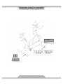
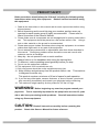
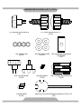
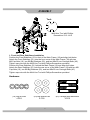
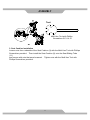
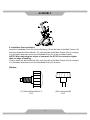
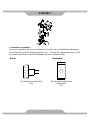
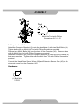
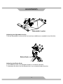
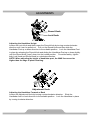
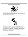
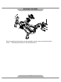
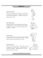
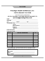
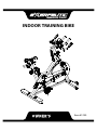
INDOOR TRAINING BIKE
OWNER’S
MANUAL
Item #1230
TABLE OF CONTENTS
SERVICE ------------------------------------------------------------------------ 2
WARNING LABEL PLACEMENT ------------------------------------------ 3
PRODUCT SAFETY ---------------------------------------------------------- 4
OVERVIEW DRAWING ------------------------------------------------------ 5
PART LIST ----------------------------------------------------------------------- 6
HARDWARE PACKING LIST & TOOL -----------------------------------ASSEMBLY ---------------------------------------------------------------------- 9
COMPUTER --------------------------------------------------------------------- 17
ADJUSTMENTS ---------------------------------------------------------------- 20
EMERGENCY STOP ----------------------------------------------------------23
MOVING THE BIKE ----------------------------------------------------------- 24
TROUBLE SHOOTING & MAINTENANCE ----------------------------- 25
WARM UP ----------------------------------------------------------------------- 26
WARRANTY -------------------------------------------------------------------- 27
FAX FORM ---------------------------------------------------------------------- 28
1
8
SERVICE
IMPORTANT: FOR NORTH AMERICA ONLY
To request product service and order
replacement parts, please call our
customer service department at:
1-866-924-1688
Monday through Friday, 8:00 AM-5:00 PM Pacific Standard Time,
or email us at: [email protected]
Please visit our website at www.paradigmhw.com.
Please have the following information ready when requesting for service:
Your name
Phone number
Model number
Serial number
Part number
Proof of Purchase
Before returning this product to the store please contact
customer service at the contact number.
Paradigm Health & Wellness, Inc.
1189 Jellick Ave,
City of Industry, CA 91748, USA
2
WARNING LABEL PLACEMENT
3
PRODUCT SAFETY
Basic precautions should always be followed, including the following safety
instructions when using this equipment. Read all instructions before using
this equipment.
1. Read all the instructions in this manual and do warm up exercises before using
this equipment.
2. Before exercising and to avoid injuring your muscles, perform warm-up
exercise for each muscle group is highly recommended. Please refer to
Warm Up section of the Owner’s Manual.
3. Please make sure all components are not damaged and in working order before
use. This equipment should be placed on a flat surface while in use. Using a
mat or other material on the ground is recommended.
4. Please wear proper clothes and shoes when using this equipment; do not wear
clothes that might catch in any part of the equipment.
5. Do not attempt any maintenance or adjustments other than those described in
this manual. Should any problems arise, discontinue use and consult with
customer service at Paradigm.
6. Keep dry - do not operate in wet or moist condition.
7. Always hold on to the handlebar while using the training bike.
8. To dismount, reduce pedaling speed gradually before you stop.
9. Do not use the equipment outdoors.
10. This equipment is for household use only.
11. Only one person should be on the equipment at any time.
12. Keep children and pets away from the product while in use.
This machine
is designed for adults only.
This product requires a minimum of 6 feet of space for safe operation.
13. If you feel any chest pains, nausea, dizziness, or short of breath, you should
stop exercising immediately and consult your physician before continuing.
14. The maximum weight capacity for this product is 325 lbs/147 kgs.
WARNING: Before beginning any exercise program consult your
physician.
This is especially important for the people who are over 35 years
old or who have pre-existing health problems.
Read all instructions before
using any fitness equipment.
CAUTION: Read all instructions carefully before operating this
product.
Retain this Owner’s Manual for future reference.
4
OVERVIEW DRAWING
5
PART LIST
No.
Description
001 Handlebar End Cap (Ø25.4x2.0)
Qty No.
Description
Qty
6
029 Transport Wheel (Ø64x24)
2
002
Handlebar Foam Grip
Ø33xØ23x290
2
030 Nylon Nut M8
2
003
Handlebar Foam Grip
Ø33xØ23x220
2
031 Front Stabilizer (80x40x1.5tx600)
1
004 Left Elbow Protective Pad
1
032 Water Bottle
1
005 Elbow Protective Bracket
2
033 Water Bottle Holder
1
006 Handlebar
1
034 Bolt M5x16
4
007 Curve Washer Ø6
2
035 Right Foot Pedal 9/16"
1
008 Lock Nut M6 (Ø42x23)
2
036 Right Crank with Chain Wheel
1
009 Seat Cushion
1
037 Brake Knob Ø55
1
2
038 Left Crank
1
011 Seat Sliding Tube
1
039 Rectangle End Cap (80x40x1.5)
4
012 Square Nut (26x26x12)
1
040 Carriage Bolt M8x55mm
4
013 Adjustment Knob M10
2
041 Bolt M6x6
2
014 Seat Post
1
042 Computer (ST7604-67)
1
015 Left Foot Pedal 9/16"
1
043 Computer Bracket
1
016 Bushing (80x40x1.5)
2
044 Bolt M6x15
2
017 Round Knob M16x1.5
2
045 Extension Sensor Wire
1
018 Main Frame
1
046 Small Spring Plate (36x15.5x2)
1
019 Cap Nut M8
4
047 Brake Knob Sticker
1
020 Big Washer Ø8
5
048 Nut M10x1.25
2
021 Rear Stabilizer (80x40x1.5tx600)
1
049 Crank Cover
2
022 Adjustable Leveler Ø42.5
4
050 Inner C Ring D40
2
023 Right Elbow Protective Pad
1
051 Bearing 6203ZZ
2
024 Handlebar Post
1
052 Brake Knob Rod (Ø10x190)
1
1
053 Brake Block (19x19x10)
1
026 Lock Knob M8
2
054
Brake Knob Rod Sleeve
(Ø15.1x100)
1
027 Hexagon Head Bolt M8x40
2
055 Cap Nut M12
1
028 Hand Pulse Sensor with Wire
2
056 Bolt M5x12
1
010
025
Seat Sliding Tube Square End
Cap (□30x1.5)
Handlebar Adjustment Knob
Plate
6
PART LIST
No.
Description
Qty No.
Description
Qty
057 Nut M5
2
074 Inner Chain Cover
1
058 Brake Plate (140x25x13)
1
075 Axle Ø20x135
1
059 Spring Plate
1
076 Chain
1
060 Bolt M6x12
2
077 Bolt M5x8
1
061 Cap Nut M10x1.0
2
078 Outer Chain Cover
1
062 Spring Washer Ø10
2
079 Flywheel Sleeve (Ø14x1.5x12.5)
1
063 Eyebolt M6
2
080 Nut M10x1.0x5.7mm
3
064 Screw ST4.2x19
2
081 Flywheel Axle (Ø10x149)
1
065 Spring Washer Ø6
2
082 Bearing 608ZZ
3
066 Nut M6
2
083
067 Round Nut M6
2
084 Flywheel Bushing Ø80
1
068 Brake Pad (140x26x6)
1
085 Flywheel Sleeve (Ø14x1.5x56.7)
1
069 Washer Ø5
5
086 Flywheel Ø460
1
070 Oval End Cap 60x30x1.5
2
087
071 Wire Grommet
2
088 Sensor with Wire
1
072 Bolt M5x20
2
089 Plastic Flexible Tube Ø10xØ10x85
2
073
Pan Head Phillips Self Tapping
Screw ST4.2x19
5
7
Hexagon Socket Head Cap Bolt
M6x20
Pan Head Phillips Self Tapping
Screw ST2.9x10
4
2
HARDWARE PACKING LIST & TOOL
(13) Adjustment Knob M10
1 PC
(17) Round Knob M16x1.5
2 PCS
(19) Cap Nut M8
4 PCS
(20) Big Washer Ø8
4 PCS
(25) Handlebar Adjustment
Knob Plate
1 PC
(26) Lock Knob M8
2 PCS
(34) Bolt M5x16
2 PCS
(40) Carriage Bolt M8x55mm
4 PCS
(41) Bolt M6x6
2 PCS
Multi Hex Tool with Phillips Screwdriver S13-14-15
1 PC
8
ASSEMBLY
Tool:
Multi Hex Tool with Phillips
Screwdriver S13-14-15
1. Front and Rear Stabilizers Installation
Position the Front Stabilizer (31) in front of the Main Frame (18) and align bolt holes.
Attach the Front Stabilizer (31) onto the front curve of the Main Frame (18) with two
M8 Cap Nuts (19), two Ø8 Big Washers (20), and two M8x55 mm Carriage Bolts (40).
Tighten cap nuts with the Multi Hex Tool with Phillips Screwdriver provided.
Position the Rear Stabilizer (21) behind the Main Frame (18) and align bolt holes.
Attach the Rear Stabilizer (21) onto the rear curve of the Main Frame (18) with two M8
Cap Nuts (19), two Ø8 Big Washers (20), and two M8x55 mm Carriage Bolts (40).
Tighten cap nuts with the Multi Hex Tool with Phillips Screwdriver provided.
Hardware:
(19) Cap Nut M8
4 PCS
(20) Big Washer Ø8
4 PCS
9
(40) Carriage Bolt M8x55mm
4 PCS
ASSEMBLY
2. Seat Post Installation
Insert the Seat Post (14) into the Bushing (16) on the tube of the Main Frame (18) and
then attach the Round Knob (17) onto the tube of the Main Frame (18) by turning it
in a clockwise direction to lock the Seat Post (14) in the suitable position.
NOTE: When adjusting the height of seat post, the STOP line cannot be higher
than the edge of bushing.
Finally, attach the M8 Lock Knob (26) onto the tube of the Main Frame (18) by turning it
in a clockwise direction to lock the Seat Post (14) in place.
Knobs:
(17) Round Knob M16x1.5
1 PC
(26) Lock Knob M8
1 PC
10
ASSEMBLY
Tool:
Multi Hex Tool with Phillips
Screwdriver S13-14-15
3. Seat Cushion Installation
Loosen nuts from underside of the Seat Cushion (9) with the Multi Hex Tool with Phillips
Screwdriver provided. Then install the Seat Cushion (9) onto the Seat Sliding Tube
(11)
and secure with nuts that were loosened. Tighten nuts with the Multi Hex Tool with
Phillips Screwdriver provided.
11
ASSEMBLY
4. Handlebar Post Installation
Insert the Handlebar Post (24) into the Bushing (16) on the tube of the Main Frame (18)
and then attach the Round Knob (17) onto the tube of the Main Frame (18) by turning it
in a clockwise direction to lock the Handlebar Post (24) in the suitable position.
NOTE: When adjusting the height of seat post, the STOP line cannot be higher
than the edge of bushing.
Finally, attach the M8 Lock Knob (26) onto the tube of the Main Frame (18) by turning it
in a clockwise direction to lock the Handlebar Post (24) in place.
Knobs:
(17) Round Knob M16x1.5
1 PC
(26) Lock Knob M8
1 PC
12
ASSEMBLY
5. Handlebar Installation
Attach the Handlebar (6) onto the Handlebar Post (24) with one Handlebar Adjustment
Knob Plate (25) and M10 Adjustment Knob (13). Turn the M10 Adjustment Knob (13) in
a clockwise direction to lock the Handlebar (6) in the suitable position.
Knob:
Hardware:
(13) Adjustment Knob M10
1 PC
(25) Handlebar Adjustment
Knob Plate
1 PC
13
ASSEMBLY
Tool:
Multi Hex Tool with Phillips
Screwdriver S13-14-15
6. Water Bottle Holder Installation
Attach the Water Bottle Holder (33) onto the Main Frame (18) with two M5x16 Bolts (34).
Tighten bolts with the Multi Hex Tool with Phillips Screwdriver provided.
Install the Water Bottle (32) into the Water Bottle Holder (33).
Hardware:
(34) Bolt M5x16
2 PCS
14
ASSEMBLY
Tool:
Multi Hex Tool with Phillips
Screwdriver S13-14-15
7. Foot Pedals Installation
The Cranks, Pedal Shafts, and Foot Pedals are marked “R” for Right and “L” for
Left.
Insert the pedal shaft of Left Foot Pedal (15) into threaded hole in the Left Crank (38).
Turn the pedal shaft by hand in the counter-clockwise direction until snug.
Note: DO NOT turn left foot pedal shaft in the clockwise direction, doing so will
strip the threads.
Tighten the pedal shaft of Left Foot Pedal (15) with the Multi Hex Tool with Phillips
Screwdriver provided.
Insert pedal shaft of Right Foot Pedal (35) into threaded hole in Right Crank (36). Turn
the pedal shaft by hand in the clockwise direction until snug. Tighten pedal shaft of
Right Foot Pedal (35) with the Multi Hex Tool with Phillips Screwdriver provided.
Note: DO NOT turn right foot pedal shaft in the counter-clockwise direction, doing
so will strip the threads.
15
ASSEMBLY
Tool:
Multi Hex Tool with Phillips
Screwdriver S13-14-15
8. Computer Installation
Attach the Computer Bracket (43) onto the Handlebar (6) with two M6x6 Bolts (41).
Tighten bolts with the Multi Hex Tool with Phillips Screwdriver provided.
Remove two M6x15 Bolts (44) from the back of the Computer (42). Remove bolts
with the Multi Hex Tool with Phillips Screwdriver provided.
Attach the Computer (42) onto the Computer Bracket (43) with two M6x15 Bolts (44)
that were removed. Tighten bolts with the Multi Hex Tool with Phillips Screwdriver
provided.
Connect the Hand Pulse Sensor Wires (28) and Extension Sensor Wire (45) to the
wires that come from the Computer (42).
Hardware:
(41) Bolt M6x6
2 PCS
16
COMPUTER
POWER ON
1.
Plug in the power supply or press the RESET key for 2 seconds to start the
console. LCD will display all segments for 2 seconds (FIGURE 1) with a beep
sound. The flywheel dia. “78.0” will display in the DISTANCE column
(FIGURE 2) and the LCD will display current temperature, date and time.
FIGURE 1
FIGURE 2
2.
Use the SET key to adjust TIME, DISTANCE, and CALORIES when setting and
press the MODE key after value’s determined. Press the RESET key clear all
pre-set values.
2-1 Use the SET key to adjust maximum heart rate value for PULSE; system will
have a beep sound as a reminder when the current heart rate exceeds the
pre-set value.
17
COMPUTER
2-2 When a RPM signal is detected, the icon
will disappear and the icon
will light up (FIGURE 3-4). When a pre-set value reaches to zero, console
system will have beep sound as a reminder.
2-3 The icon
will show 3 seconds after no RPM signal’s detected.
FIGURE 3
FIGURE 4
3. RECOVERY MODE:
3-1 RECOVERY function is only valid when there’s a heart rate input’s detected.
3-2 Press the RECOVERY key and LCD will display 60 seconds counting down
(FIGURE 5) and if the heart rates signal stops, LCD will display “F6”. When it
reaches to “0:00”, LCD will display result FX (X=1~6) (FIGURE 6).
FIGURE 5
FIGURE 6
3-3 Before time reaches to 0:00, user can press the RECOVERY key to go back to
the previous display.
3-4 RECOVERY result FX will continue displaying on screen until the user presses
the RECOVERY key again or system will go to SLEEP mode after 4 minutes.
18
COMPUTER
4.
5.
Computer system will wake up if there’s any signal input detected (or press any
key).
Computer system will switch to power save mode if there’s no signal input
detected for more than 4 minutes. Reboot the computer and all pre-set and
exercise values will be saved.
HOW TO INSTALL THE BATTERIES:
1. Remove the battery cover on the back of the computer.
2. Place two "SIZE-AAA" batteries into the battery housing.
3. Insure batteries are correctly positioned and battery springs are proper contact with
batteries.
4. Re-install the battery cover.
5. If the display is illegible or only partial segment appear, remove batteries and wait
15 seconds before reinstalling.
19
ADJUSTMENTS
Adjustable Leveler
Adjusting the Adjustable Leveler
Turn the Adjustable Leveler on the front and rear stabilizers as needed to level the bike.
Brake Knob
Adjusting the Brake Knob
To increase the load, turn the Brake Knob in a clockwise direction.
To decrease the load, turn the Brake Knob in a counterclockwise direction.
20
ADJUSTMENTS
Round Knob
Lock Knob
Adjusting the Handlebar Height
Loosen the Lock Knob and then loosen the Round Knob by turning counterclockwise
direction until it can be pulled out. Pull out the Round Knob and then slide the
Handlebar Post up or down direction to the suitable position. Lock the Handlebar Post
in place by releasing the Round Knob and sliding the Handlebar Post up or down slightly
until the Round Knob "pops" down into the locked position. For added safety, tighten
both Lock Knob and Round Knob in a clockwise direction.
NOTE: When adjusting the height of handlebar post, the MAX line cannot be
higher than the edge of plastic bushing.
Adjustment Knob
Adjusting the Handlebar Forward or Back
Loosen the Adjustment Knob by turning counterclockwise direction. Slide the
Handlebar forth or back direction to the suitable position. Lock the Handlebar in place
by turning clockwise direction.
21
ADJUSTMENTS
Lock Nut
Adjusting the Left/Right Elbow Protective Pads
Loosen the Lock Nut by turning counterclockwise direction. Slide the Left/Right Elbow
Protective Pad right or left direction to the suitable position. Lock the Elbow Protective
Pad in place by turning clockwise direction.
Lock Knob
Round Knob
Adjusting the Seat Height
Loosen the Lock Knob and then loosen the Round Knob by turning counterclockwise
direction until it can be pulled out. Pull out the Round Knob and then slide the Seat
Post up or down direction to the suitable position. Lock the Seat Post in place by
releasing the Round Knob and sliding the Seat Post up or down slightly until the Round
Knob "pops" down into the locked position. For added safety, tighten both Lock Knob
and Round Knob in a clockwise direction.
NOTE: When adjusting the height of handlebar post, the MAX line cannot be
higher than the edge of plastic bushing.
22
EMERGENCY STOP
Adjustment Knob
Adjusting the Seat Forward or Back
Loosen the Adjustment Knob by turning counterclockwise direction. Slide the Seat
Sliding Tube forth or back direction to the suitable position. Lock the Seat Sliding Tube
in place by turning clockwise direction.
EMERGENCY STOP
To emergency stop, press firmly down onto the BRAKE KNOB. Continue holding the
BRAKE KNOB down until the flywheel comes to a complete stop.
23
22
22
MOVING THE BIKE
Start by carefully pushing down on the handlebar until the rear end of the bike lifts in
the air. Carefully push the bike to the desired location.
24
TROUBLE SHOOTING & MAINTENCE
TROUBLE SHOOTING
PROBLEM: The training bike wobbles when in use.
SOLUTION: Turn the adjustable leveler on the front and rear stabilizers as needed
to level the training bike.
PROBLEM: There is no display on the computer console.
SOLUTION: Verify the extension sensor wire is properly connected to the wire that
comes from the computer.
SOLUTION: Check if the batteries are correctly positioned and battery springs are
in proper contact with batteries.
SOLUTION: The batteries in the computer console may be dead. Replace with
new batteries.
PROBLEM: There is no heart-rate reading or there is erratic / inconsistent reading.
SOLUTION: Verify the hand pulse sensor wires are properly connected to the wires
that come from the computer.
SOLUTION: To ensure the pulse readout is more precise, always hold on to the
handlebar grip sensors with both hands instead of just with one hand.
SOLUTION: Avoid gripping the hand pulse sensors too tight. Try to maintain
moderate pressure while holding onto the hand pulse sensors.
PROBLEM: The training bike makes a squeaking noise when in use.
SOLUTION: The bolts may be loose on the training bike. Please inspect all of the
bolts and tighten any loose bolts.
MAINTENANCE
Cleaning
The training bike can be cleaned with a soft cloth and mild detergent. Do not use
abrasives or solvents on plastic parts. Please wipe your perspiration off the
training bike after each use. Be careful not to get excessive moisture on the
computer display panel as this might cause an electrical hazard or electronics to
fail.
Please keep the training bike, especially, the computer console, out of direct
sunlight to prevent screen damage.
Please inspect all assembly bolts and pedals on the machine for proper tightness
every week.
Storage
Store the bike in a clean and dry environment away from children.
25
WARM UP
Quadriceps Stretch
With one hand against a wall for balance, reach behind
you and pull your right foot up. Bring your heel as close
to your buttocks as possible. Hold for 15 counts and
repeat with left foot up.
Inner Thigh Stretch
Sit with the soles of your feet together with your knees
pointing outward. Pull your feet as close to your groin
as possible. Gently push your knees towards the floor
and hold for 15 counts.
Toe Touching
Slowly bend forward from your waist, letting you back and
shoulders relax as you stretch toward your toes. Reach
down as far as you can and hold for 15 counts.
Hamstring Stretch
Sit with your right leg extended. Rest the sole of your left
foot against your right inner thigh. Stretch toward your
toe as far as possible. Relax and hold for 15 counts.
Repeat with left leg extended.
26
WARRANTY
Paradigm Health & Wellness, Inc. warrants to the original purchaser that this
product is free from defects in material and workmanship when used for the
purpose intended, under the conditions that it has been installed and operated in
according to Paradigm Health & Wellness, Inc.’s Owner’s Manual. Paradigm
Health & Wellness, Inc.’s obligation under this warranty is limited to replacing free
of charge, any parts which may prove to be defective under normal home use.
This warranty does not include any damage caused by improper operation,
misuse or commercial application. From the date of purchase, the product is
warranted to be free from defects for 1 (one) year. All parts and workmanship,
including computer display, upholstery, foam, ball bearings, pulleys, belts, cables,
wires, shocks, covers, tension, internal mechanism, wheels, pedals, knobs,
accessories and hardware are to be free from defects for 90 days. This warranty
is offered only to the original owner and is not transferable. Proof of purchase is
required. This warranty is offered only to the original owner and is not
transferable.
Ordering Replacement Parts
Replacement parts can be ordered by calling or emailing our customer service
department
[email protected]
1-866-924-1688
Monday through Friday, 8:00 AM - 5:00 PM (PST).
When ordering replacement parts please have the following information ready:
1. Owner’s Manual
2. Model Number
3. Description of Parts
4. Part Number
5. Date of Purchase
27
FAX FORM
Paradigm Health & Wellness, Inc.
PARTS REQUEST FAX FORM
Please fax this form to (1-626-810-2166)
OR YOU CAN EMAIL CUSTOMER SERVICE REQUESTS TO
[email protected]
NAME: _______________________________________________________
ADDRESS: ____________________________________________________
CITY ______________ STATE ______________ ZIP ___________________
TELEPHONE: (Day) _____________________________________________
(Night) ____________________________________________
(Email Address) ____________________________________
SERIAL#: __________________________________________
MODEL#: __________________________________________
PURCHASE DATE: ______________________________________________
PURCHASE FROM: ______________________________________________
PART #
DESCRIPTION/REASON
QTY
“YOUR ORDER WILL BE PROCESSED WITHIN 3 BUSINESS DAYS”
OFFICIAL USE ONLY
SHIP DATE: ___________________________________________
TRK #: _______________________________________________
BACK ORDER: ________________________________________
28