1
2006:61 PB
2007:061
TH
M MASTE
A S T E RR’S
'S T
H ESIS
ESIS
Motion Control for Mobile Robots
Konrad R. Skup
Luleå University of Technology
Master Thesis, Continuation Courses
Space Science and Technology
Department
of Department
Space Science,
Department
of SpaceofScience,
Kiruna Kiruna
Universitetstryckeriet, Luleå
2007:061 - ISSN: 1653-0187 - ISRN: LTU-PB-EX--07/061--SE
CZECH TECHNICAL UNIVERSITY IN PRAGUE
FACULTY OF ELECTRICAL ENGINEERING
DEPARTMENT OF CONTROL ENGINEERING
DIPLOMA THESIS
Motion Control for Mobile Robots
Depart ment of
Control Engineering
Depart ment of Space Science
Kiruna Space Campus
ERASMUS MUNDUS SPACE MASTER PROGRAM
Prague, 2007
Konrad R. Skup
Declaration of authorship:
I declare, that I wrote this diploma thesis myself only with the help of the literature, on-line
materials, projects and others examples which are available for educational purposes.
Prague, 29.05.2007
Konrad R. Skup
2
Abstract
This diploma thesis is focused on brushless DC motors, how they work and how to control them
using phase tables. It describes the internals of existing motion control library (PXMC) and provides
documentation of its elements, which were published under GPL license. Additionally it presents
extensions of PXMC library, which were made to control two brushless motors with help of
Renesas’ H8S/2638 microcontroller. It introduces a modularization of PXMC and software for hall
sensor table and index mark detection. The target application is a mobile robot for Eurobot
competition.
3
Table of Contents:
1.
Introduction.............................................................................................................................6
2.
Terminology and abbreviations. ............................................................................................8
3.
Brushless DC motors. ............................................................................................................10
3.1. Overview. ........................................................................................................................10
3.2. Description. ....................................................................................................................10
3.3. Hall sensor. .....................................................................................................................14
3.4. Incremental encoders. ...................................................................................................15
3.5. General work of brushless motor..................................................................................17
3.6. Putting everything together. .........................................................................................19
4.
H8S/2638 microcontroller....................................................................................................21
4.1. Overview. ........................................................................................................................21
4.2. PWM description. ...........................................................................................................23
4.3. Interrupts description. ..................................................................................................26
5.
PXMC library. .........................................................................................................................30
5.1. Introduction....................................................................................................................30
5.2. Preparation of the programming environment. ..........................................................32
5.3. Overview. ........................................................................................................................33
5.3.1.
General overview of files. .......................................................................................33
5.3.2.
General work of PXMC. ...........................................................................................35
5.3.3.
PXMC.H ....................................................................................................................35
5.3.4.
PXMC_BASE.H ..........................................................................................................44
5.3.5.
PXMC_CON_PID.C .....................................................................................................44
5.3.6.
PXMC_DEB.C ............................................................................................................45
5.3.7.
PXMC_GEN_INFO.H ..................................................................................................46
5.3.8.
PXMC_GEN_SPDTRP.C .............................................................................................46
5.3.9.
PXMC_HH.C ..............................................................................................................47
5.3.10.
PXMC_HH_BASIC.C ...............................................................................................48
5.3.11.
PXMC_INP_COMMON.H ........................................................................................48
5.3.12.
PXMC_INTERNAL.H..............................................................................................48
5.3.13.
PXMC_PTABLE.C ..................................................................................................49
5.4. How to start work with the PXMC. ................................................................................51
6.
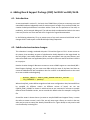
Adding Board Support Package (BSP) for BLDC on H8S/2638. ..........................................53
6.1. Introduction....................................................................................................................53
6.2. Subdirectories structure changes. ................................................................................53
6.3. Changes in PXMC original code. ....................................................................................54
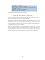
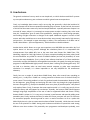
6.4. Work with hi_cpu2 board. .............................................................................................55
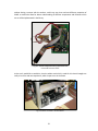
6.5. Work with Eurobot.........................................................................................................59
6.6. Application for “index marking” and hall sensors table detection. ............................60
4
7.
Testing and documentation of the code. ..............................................................................65
7.1. Introduction....................................................................................................................65
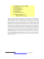
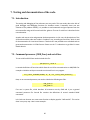
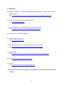
7.2. Command processor (CMD_Proc) and serial line.........................................................65
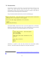
7.3. Documentation. ..............................................................................................................67
8.
Conclusions. ...........................................................................................................................69
9.
Sources. ..................................................................................................................................71
Appendix A
Appendix B
5
1. Introduction
Motors are widely used in many aspects of our life. They serve in different trivial tasks like
rotation of wheels in toys up to complicated works demanding very high level of accuracy like
for example in military and space applications or humanoid robots. One kind from a huge family
of motors are presented later brushless DC motors, which due to their several advantages are
getting more and more popular and recently were used even in the most demanding tasks ,
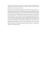
including space missions, for example: robots Spirit and Opportunity on Mars use brushless
motors to rotate their wheels.
Fig. 1-1. Spriti – robot on Mars.
Unfortunately, nowadays even the fastest, strongest and most accurate motors are totally
useless without microcontroller or some other devices. Only external electronics can properly
control them and provide suitable voltages and currents. This is mostly due to the very
complicated way of the motor control process. Of course one single microcontroller or even
microprocessor alone is also not enough. We need something more, some special program
which is executed by the microcontroller and then used to control the motor.
Because of this last need, on CTU in Prague, there was created a library called PXMC. PXMC is
some kind of interface or even more, we can think about it as a collection of functions, which
can be used to control different kind of motors. Because PXMC is also hardware independent so
it is possible to use it on many different microcontrollers mounted on different boards. Only one
limitation in this field is that there must be existing gcc compiler for a desired microcontroller.
What is also important, PXMC is under GPL license, so everyone can use it for its own purposes
free of charge.
6
Finally, even the best software and libraries are useless without good documentation and
examples how to use them. Because of that, later in this document there is described the whole
PXMC and how to use it, to meet desired needs.
All of above mentioned thing are presented in this document. In the second chapter, I’m
discussing all very important terms and abbreviations which can be a key element for proper
understanding of the described topics. In the chapter number three I put information about the
brushless DC motors, how they work, how to control them and what should we know about
them. Forth chapter covers H8S/2368 microcontroller from Renesas which was used to test and
later extend PXMC library. This microcontroller was also used for control of motor built for
Eurobot competition. Chapter number five contains the total documentation of PXMC. It has
description of all files, functions, flags and errors which developer can meet during his work with
it. In the next two chapters: sixth and seventh, I described my work with PXMC. These
subsections include information about Board Support Package, how to use or extend it and
eventually how to improve its code. We find there also which tools were use to create
documentation added in Appendix A and B. Last two chapters contain only my own opinion
about new things which I learned and information about sources which I used during my
adventure with writing this document.
7
2. Terminology and abbreviations.
Below are presented the most important terms and abbreviations which are later used in this
document.
0x – It denotes that we are using hexadecimal number. For example: 0xff means 255 in decimal
system, 0x1f means 31 (in decimal system).
AC – Alternating Current
Commutation – “the action of applying currents or voltages to the proper electrical motor phases so
as to produce optimum motor torque at a motor's shaft”1.
Commutation point – It is a point where two phases produce equal levels of torque.
Compare match – A comparison between some two registers, which gives the result as true if two
registers have the same value or false if they have different values.
DC – Direct Current
IRC – (Incremental Radial Counter) Sensor which makes measurement of relative position of the
rotor. The actual position of the motor can be calculated by the sum of pulses received form IRC.
Index – A value which describes the actual position in some array. In this document the “index”
points to the actual position in the phase table(s).
Index mark – Starting point or point used to make synchronization of the rotating motor.
Phase table – An array which contains values describing sinusoid or other function. It is used for
proper calculations of a voltage which should be sending to the motor to cause its rotation.
PXMC – (Pikron eXtensible Motion Control) Library for control different types of motors.
PXMC structure – A data structure which contains all necessary parameters needed for rotation of
the motor.
PWM – Pulse Width Modulation
1
http://en.wikipedia.org
8
Servo – shortcut of Servomechanism – a special motor that typically includes a velocity and/or
position feedback device.
Sinusoidal current wave – It is a graphical or mathematical representation of changes in the current,
which has the shape of a sinus function.
9
3. Brushless DC motors.
3.1. Overview.
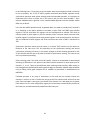
A brushless DC motors, very often denoted by shortcut BLDC (BrushLess Direct Current), are
popular synchronous electric motors widely used in industry, especially in Appliances,
Automotive, Aerospace, Consumer, Medical, Industrial Automation Equipment and
Instrumentation. Characteristic property of this motor kind is that instead of brushes for
commutation it uses electronically-controlled commutated system. Brushless motors have
several advantages, and some of them are:
- good speed versus torque characteristic
- high dynamic response
- high efficiency
- long operating life
- silent during operation
- high speed
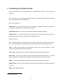
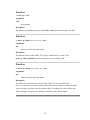
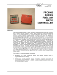
- high torque versus the size of the motor
Fig. 3.1-1. REO-20 brushless motor from Maxon.
A very good confirmation of all above features is already mentioned at the beginning of this
document fact that brushless motors were sent to Mars on board two rovers: Spirit and
Opportunity.
3.2. Description.
Generally we can distinguish two types of brushless motors: trapezoidal and sine wave. First one
is really a brushless DC servo. Second kind has close similarity to the AC synchronous motors.
Later in this section I'll shortly show the main differences between these two types of motors.
Now, let’s look inside and find out how the brushless motors are build.
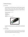
10
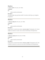
Fig. 3.2-1. Basic schematics of brushless motor.
The basic schematic of a brushless motor is shown on the picture 3.2.1. First of all, brushless
motors don't have windings on the rotor. The meaning of this is that here the rotating part is
permanent magnet and the windings are placed on the stator poles. Additionally for proper
functioning we need something what can automatically reverse the current. This can be
achieved in two different ways. First is a mechanical approach, where we can use a camoperated reversing switch. Second possibility is to use an electronic amplifier which allows us to
do the commutation in response to low-level signals from an optical or hall-effect sensor. The
general conclusion of above is that we can't just connect our motor to a current source, because
the current in external circuit must be reversed at strict defined position of the rotor. This last
requirement can be very good solved by the use of some microcontroller – for example
H8S/2638 described in the next chapter.
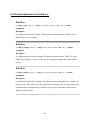
Second thing which is important to understand brushless motors is a placement of windings.
Assuming that we have three phase design motor, we can connect them in two ways. First is
called “Y” or star composition, and second is Δ delta composition. In both cases the partial
windings are shifted by 120o. Both arrangements can be seen on the following picture:
Fig. 3.2-2. Windings in brushless motor.
11
The above presented differences in arrangement change the speed and torque inversely
proportional to the factor of:
rule in the motor selection.
. Of course the arrangement of the windings doesn't have crucial
Fig.3.2-3. Coils and poles inside brushless motor.
As presented on the figure nr 3.2-3 as a typical brushless motor has three sets of coils called
“phases”. This motor has also 2 poles. In normal case the rotor has four or six poles with
corresponding higher number of stator poles. Mentioned here the increase in the number of
poles doesn't have influence to the number of phases.
We know from the basic physics that the torque is at the maximum when the magnetic field is
perpendicular to the object on which we want to act. Due to this rule, we always try to set the
stator field and rotor at 90o degree each other. Now, to keep the torque as constant we should
always keep above angle at 90o. Looking at schematics on the picture nr 3.2-3 we find out that if
we are able only to switch phase voltages on and off it is impossible for us to meet above
mentioned condition. This is due to the limit in the number of phases. In above example we
have 3 phases so the minimal resolution is 60o degree and only by this minimal value we can
change the stator field direction. Hopefully, there exists small trick which we can use to be very
close to 90o. The basic graphical idea is presented on the following picture nr 3.2-4:
Fig. 3.2-4. Stator and rotor magnetic field.
12
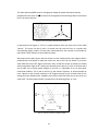
Explanation of this figure is quite short and easy. As we know from previous pictures, we
consider situation when we have only three phases. This means we can move stator filed only
with resolution of 60o. Let’s start with a difference in angle between the rotor and the stator
field equal to 120o and wait till the rotor rotates by 60o. As the result we will get the difference
equal only to 60o. At the same time we change the stator field direction by 60o in the rotation
direction what gives us as a result the situation analogical to the initial conditions. The most
important now is that the average difference in the above is 90o. This can be very easily
calculated in following manner:
. The final result is almost exactly what we
wanted. Below picture presents the rotor position at different commutation points.
Fig. 3.2-5. Rotor position at commutation point.
Now as I promised at the beginning of this section, we will look shortly and try to explain the
basic differences between a trapezoidal and a sin wave motor.
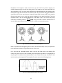
Let’s start with the trapezoidal motor. When a current has fixed level in the windings (for
example 3A), then the use of the sinusoidal torque characteristic provides to a large degree of
torque ripple. To minimize this unwanted effect we can “flatten” the torque characteristic and
make it similar to the trapezoidal. The example of it can be seen on the following picture:
Fig. 3.2-6. Trapezoidal characteristic of a torque.
13
Of course presented in above figure situation due to some non-linearity effects is very hard to
realize. The effect of non-linearity can be observable when the motor is running very slowly as a
slight kick at the commutation points. There is also a second drawback. Namely, the nonlinearity and ripple in the torque tend to produce a velocity modulation in the load. Fortunately,
in a system with a velocity feedback and high gain even small changes in the velocity will
produce big error signals, what gives us demands to change the torque in such a way to keep
the velocity as constant.
In the sine wave motor in difference to the trapezoidal motor we don't change the basic
sinusoidal torque characteristic. We can think about this motor that it is possible to run this
motor by applying sinusoidal currents to the motor windings. Of course, each of these currents
must have the phase shifted by 120o. Now if we want to have a smooth rotation at low speeds
and without torque ripples we need a high resolution device to control the commutation. This
device in general is more complicated than resolver for the trapezoidal motor, because we need
some reference table from which it can generate the sinusoidal currents, which additionally are
multiplied by the torque demand signal. This last operation allows determining the absolute
amplitude of the currents. It is good to mention that in 3-phase motor, it is sufficient to
determine the currents in two of the windings and this will give us automatically the information
about the third one. In this kind of the motor we also need some feedback loop, but we are not
limited only to the velocity. In other words, in the feedback loop we can put velocity or position
as well and at the end we will get the same effect.
3.3. Hall sensor.
According to the basic definition a hall sensor is a special kind of sensor or device which works
on base of the “Hall Effect” to make measurements of the magnetic field and current. Hall
sensors can be use for switching, positioning, speed detection and current sensing. All of these
features are very useful and were adopted into the brushless motors. Namely, it goes out, that
hall sensors are very useful in detecting the actual position of the rotor. In the already presented
example with 3-phases motor, there are 3 hall sensors. We can read the binary output states on
them, and then we can calculate the actual position of the rotor. Unfortunately, the resolution
in this approach is not too high and is only 60o.
14
The small example how the Hall Sensor can be used to read the rotation of the rotor is
presented on the figure 3.3-1.
Fig. 3.3-1. Example how we can read impulses from Hall Sensor.
3.4. Incremental encoders.
Incremental encoder is a device which is used to measure the speed and a position. The general
idea of this tool is to converts motion into a sequence of digital pulses. Later, counting these
pulses we are able to estimate the relative or absolute position and the speed of the movement.
There are two configurations of encoders: linear and rotary. This last configuration has
additionally two forms: absolute and incremental. In absolute encoder, we have a unique
sequence of pulses for each rotational position. In incremental encoder, pulses are “equally”
produced during the shaft’s rotation, which allows us to estimate relative position of the shaft.
In most cases the encoder consists from a disk with holes, LED diode and photo sensor. The light
is continuously produced by the LED diode and when the disk rotates, the light is stopped or it
goes through some hole. When it passes through hole it is detected by the photo detector,
which generates impulse. The idea of the incremental encoder is presented on the figure 3.4-1.
Fig. 3.4-1. A typical example of rotary optical encoder.
15
At this point small explanation about IRC and its channels should be given. Firstly couple of
words about IRC. IRC is just a rotary and relative sensor which works in a similar way as was
described in previous paragraph. Secondly we need to ask about one essential thing. How do we
know in which direction our motor is rotating? The answer to this question may get closer if we
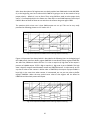
look at the following graph 3.4-2:
Fig. 3.4-2. Pulses generated in channels during rotation.
This picture presents basically how connections are made in the IRC and what kind of the output
they give. What is important for us at the moment is the small difference between the output
from the channel A and the channel B. Yes, it is not mistake. Namely, when the motor is
rotating, these two channels have 90o difference in phase and knowing this difference we are
able to find out the direction of the rotation. This property can be also used to explain why we
are using 4 in the next subsection, in the example with calculation of the phase table length.
Let’s look now at the following figure:
Fig. 3.4-3. Outputs from channels A and B during rotation.
The basic explanation of above graph is that both channels have some differences in phase and
during one cycle we can detect exactly 4 combinations of the outputs. TPU unit in
microcontroller can be set to phase shift counting mode what allows to count the number of
displacement between edges. And what does it give us? Yes, exactly as it was written in
description of the incremental encoder – it gives relative position and speed. More detailed
explanation of the phase shift counting mode can be found in next chapter in the subsection
concerned with “Interrupts description”.
16
3.5. General work of brushless motor.
As we know from the previous sections, to make the brushless motor rotating we need to put on
the three windings currents with shifted phases. In the easiest case, when we have 3-phases
motor the shift in the phases is equal to 120o. To fulfill this requirement, in most cases we will
need to use some microcontroller to control the motor. This approach provides to a first
problem. Namely, the use of a microcontroller forces us to work not with continuous signals but
with their discrete versions. What does it mean for us? The answer is very easy. We need to
make some discretization of sinusoidal currents waves. After doing this as the result we will get
a discrete phase tables with several values which correspond to real current levels. Of course at
this point, there occurs question. How many levels should have these phase tables and how
many values should they store? The answers to these questions are quite easy and depend on
the specification of the microcontroller, the motor and the library which we use to control the
motor. If it goes about the number of a phase table levels for PXMC, it should be equal to 0x7fff.
This limitation is due to 16bits (in C/C++ it is short) which are used for keeping phase table
values – because the last bit is used for sign then there stay 15bits which can give maximum
value equal to 0x7fff. If it goes about the length of phase table, we can calculate it by taking
from documentation of the motor two values: number of channels and the count per turn. After
that we just multiply them. For example, during my work with PXMC I had a motor which had 2
channels and count per turn equal to 512. Two channels give us total number of possible
combination equal to:
. The length of phase table in this case was equal to:
elements.
Let’s look now to the discretization. The short example of it is shown on the picture 3.5-1. To
make it more readable, the size of phase table was limited only to 6 level s and the number of
levers to 3.
Fig. 3.5-1. Example of discretization.
17
Looking at the above example of discretization on the figure 3.5-1 and thinking little bit, we will
find out another very important problem: it is impossible to put to the pins negative and positive
values at the same time. In other words, we can assume that the voltage levels on the pins now
are negative or positive, but we can't have them both. How to solve it? The solution is also quit
easy. We just need to shift maximum negative values to be equal to zero. True zero will be equal
to the middle level – in our case it will be 0x3fff, and the maximum positive value will be equal
to 0x7fff. Here is small mathematical explanation: range of levels is from 0-0x7fff, what gives us
0x8000 possibilities. We divide 0x8000/2 and we get 0x4000. Because we count from zero we
should decrease this value by 1 and as the final result we will get: 0x3fff. This number is also the
amplitude of sinusoids which we should generate for phase tables.
The last serious problem which we can meet, can occur at begin of our rotation. Let’s try to
imagine the situation that the rotor is in the position of
and we want to rotate it to the
right. To make it, we should put magnetic field perpendicular to the rotor field, so the angel for
the magnetic field should be equal to
. Everything seems to be quite easy,
but in real it's not. Let’s assume we run some program to control the motor and make small
analyze. If we start the program and an index for phase table will point to a good position in the
phase table then nothing wrong should happen – the magnetic field will have
. But, what if
the index will be set wrong and gives rise to wrong position of the magnetic field? The answer
depends on the error. If index will be little bit ahead of the right position only the torque will be
little bit lower, but after short time it will grow to the desired value. The same happens if the
index will be only little bit before good position. And what if the index will be behind the proper
position more than ¼ of the phase table length? In this case it will give rise to torque with wrong
direction, because the direction of magnetic field will be less than
. The worst case will be if
the index will be ½ of the phase table’s length before the proper position or in other words the
magnetic field direction generated by this position will be
to the rotor field, then the
torque will be the highest and additionally with wrong direction. What does it mean – a wrong
direction of torque? It means that the motor will start to rotate for a short time in wrong
direction. In simple application it can have no meaning, but let’s imagine that we control some
lift with heavy load, in this case such error can have catastrophic consequences.
To solve these problems we can use hall sensors presented in subsection 3.3. If not every than
at least most of the modern brushless motors have such sensors. Using hall sensors we can find
out the actual position of the motor with 60o precision and put proper voltages to the right
windings. This avoids the situation presented in the previous paragraph. It is also worth to note
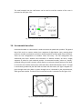
that some of the motors have IRC with so called “index mark” - please look at the picture 3.4-2
and explore the channel I. This means, that always when the motor cross some defined point,
sensor detects it and send some signal. We can use this to make some kind of synchronization
between the position of the motor and the index in the phase table. The following picture
presents the reads from hall sensors and voltages on the windings which are needed to place
the motor to the proper position.
18
Fig. 3.5-2. Position of the motor and
reading from HAL sensor.
I think it is good idea to explain little bit how we can rotate the motor in desired direction using
table presented on the figure 3.5-2. Thus, if we know from hall sensors that we are in phase I
and we want to rotate the motor into one direction all we need is just to apply positive or
negative voltages according to values shown in the table. In other words for phase I we need to
keep some positive voltage difference between 1st and 2nd windings, and the same time zero
voltage difference between 2nd and 3rd and between 3rd and 1st windings (first column in the
table). If we would like to rotate the motor into opposite direction, then we need to keep
negative voltage difference between 1st and 2nd windings, and as before zero voltage difference
between 2nd and 3rd and between 3rd and 1st windings (fourth column in the table). According to
this we can say that the change in the direction of rotation corresponds to applying inverted
voltages or using voltages which should be applied after reading hall sensor and adding 180 o. Of
course we should remember that after some time the value read from hall senor will change and
to continue of the rotation we will have to set new voltage differences between windings
according to table on the fig. 3.5-2.
3.6. Putting everything together.
In this subsection I will shortly describe how all presented above was taken and put together to
get right working motor in Eurobot project.
19
Fig. 3.6-1. Brushless motor which was used by me.
First of all we calculated the length of phase tables. We assumed that the amplitude of the
sinusoid wave will be equal to 0x3fff. Making the maximum equal to 0x7fff and the minimum
equal to 0 we were able to keep all levels inside two bytes (denoted as short in C). The rest
calculations were made exactly as described in the subsection 3.5 and the final length of our
phase tables was 4000 (phase tables with length of 2048 presented in above mentioned
examples were used only for tests with motor presented on fig. 3.6-1 and it should be said, that
this motor was not used in Eurobot project). Next we used hall sensors and block diagram
presented on the pictures nr 3.5-2 to protect against wrong direction of rotation of the motor.
As was mentioned in subsection 3.3 it can occur in the early begin when the motor starts to
rotate. In other words, we decided that at begin we will rotate motor in desired direction with
help of hall sensor. Then, when we detect “index mark” crossing, we calculate exactly position of
the index. After that we continue the rotation of the motor only with use of IRC sensors.
20
4. H8S/2638 microcontroller.
4.1. Overview.
H8S/2638 is microcomputer unit (MCU) employed by Renesas Technology. In general it is 32-bit
architecture unit with sixteen 16-bit general registers which can be used as 8-bit registers or as
eight 32-bit registers. The maximum clock speed of this microcontroller is 20MHz what is
comparable with the maximum speed of Intel's 80286 microprocessor. Of course we can't make
such comparisons, but I think it is very good way how to imagine speed limitation or slowness of
this microcontroller. Available address size allows using 16-Mbyte address space which seems to
be enough for most of the basic tasks as for example motor control.
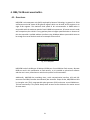
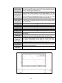
Fig. 4.1-1. H8S/2638
H8S/2638 has built in16kbytes of RAM and 256kbytes of mask ROM or flash memory. Because
ROM can work in this specification as flash memory, so it is possible to upload once software
and then use it every time when we switch on the power for microcontroller.
Additionally, H8S/2638 has watchdog timer, serial communication interface, A/D and D/A
converters and CAN (Controller Area Network) bus controller. Except of that, H8S/2638 has built
in time-pulse unit (TPU), programmable pulse generator (PPG) and motor control PWM timer.
This last functionality is very useful always when we want to use this device for motion control
of some motor.
21
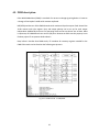
Fig. 4.1-2. The internal structure of H8S/2638.
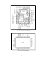
Fig. 4.1-3. Pins available in H8S/2638.
22
4.2. PWM description.
Pulse Width Modulation (PWM) is a method of a current or voltage signal regulation. It bases on
a change of the impulse’s width with constant amplitude.
H8S/2638 provides two 10-bit PWM channels with maximum 16 pulse outputs. Each channel has
10-bit counter and cycle register. Duty and output polarity can be set up for each output
independent. Additionally there are five operating clocks and we can choose one of them. What
is important, all PWM channels can work as I/O ports. Because we didn't use this property in our
Eurobot project I'll not present details about it.
Now, before I describe how PWM works, I'll introduce all necessary registers needed for t he
PWM. Schematics can be found on the following two pictures:
Fig. 4.2-1. PWM channel 1 in H8S/2638.
23
Fig. 4.2-2. PWM channel 2 in H8S/2638.
PWMOCR1 and PWMOCR2 are used to select which PWM outputs should be enabled and which
should be disabled. Selecting proper bits we can enable or disable corresponding PWM output.
PWPR1 and PWPR2 are useful for changing polarity of PWM outputs. Polarity can be direct or
inverse. Thanks PWCR1 and PWCR1 we can decide whether the PWCNT counter is enabled or
not. The same register allows us also to select the clock for corresponding channel. We can
choose: ф, ф/2, ф /4, ф /8 or ф /16, where ф is an internal frequency of the microcontroller.
Registers called PWCYR1 and PWCYR2 are PWM conversion cycles and they describe when data
from buffer register should be transferred to the duty registers (we can think about it as PWM
frequency). PWCNT1 and PWCNT2 are two 10-bit up-counters. We can't influence them directly.
They are incremented by the input clock and are used to make several comparisons described
later. PWBFR1 (A, C, E, G) and PWBFR2 (A to D) are buffer registers. We can put here 10-bits
values which will be later transferred to the duty registers. Selecting 12th bits OTS or TDS
respectively for 1st and 2nd channel we can choose to which PWM (1st channel) or duty register
(2nd channel) data should be transferred. PWDTR1 (A, C, E, G) and PWDTR2 (A to H) are so called
duty registers. These registers can't be read or write directly and values present inside them are
transferred during compare match from proper PWBFRxx registers.
24
After short description of all registers we can shortly explain how PWM works inside H8S/2638.
So, at the beginning, user has to select which PWM he is going to use. He also needs to set up
proper polarity – default it is set as direct. Then, using PWCR we need to select proper clock
source – for example ф which is the fastest one. Next step is to set PWM frequency with help of
PWCYR. When we do all of these we can switch on the counter using once again PWCR.
The question which arises now is how PWM outputs are set up? This can be very easily
presented on following pictures nr 4.2-3 and nr 4.2-4:
Fig. 4.2-3. Output on the PWM channel 1 during compare matching.
Figure 4.2-3 presents first channel which is described in the following lines. At the beginning of
the PWM period, data from buffer register PWBFR1A is transferred to duty register PWDTR1A.
Just after that, PWM unit checks OTS bits. If it is low or equal to 0, high state of the output is
present on PWM1A output. If OTS is high or equal to 1, high state is put to PWM1B. This high
state is kept till compare match between counter and PWDTR1A occurs. In other words, we can
say that till value of the counter is bellow value of PWDTR1A, the output of proper PWM1 is
kept high. In the same time when counter is incremented, we can put new value to buffer
register PWBFR1A. When the next period starts value of that register will be shifted to
PWDTR1A and the whole process will repeat.
Fig. 4.2-4. Output on the PWM channel 2 during compare matching.
25
In the case of second channel, the situation is little bit different. This is due to the differences in
the architecture of the microcontroller. We can see it very clearly comparing two pictures nr 42.1 and nr 4.2-2. In the first channel we have only four buffer registers and four duty registers
PWDTR1A, PWDTR1C, PWDTR1E and PWDTR1G. In the second channel there are still present
only four buffer registers but there are also all eight duty registers from PWDTR2A till
PWDTR2H. In the first channel so called OTS bit decides to which output data should be
transferred. In the second channel, corresponding bit is called TDS. In this case it decides not to
which output but to which duty register transfer the data. So let’s try to analyze the last picture.
As before at the beginning of PWM period PWM unit checks TDS bit in PWBFR2A and if it is 0
then it transfers data from PWBFR2A to PWDTR2A. If TDS is equal to 1, data from PWBFR2A is
transferred to PWDTR2E. Now, the output of both PWM2A and PWM2E are set to high level and
kept till counter reaches value equal to PWDTR2A or PWDTR2E respectively. Meanwhile we can
put of course new value to PWBFR2A. When the next period starts this new value will be shifted
to proper duty register and the whole process will repeat.
4.3. Interrupts description.
As already mentioned at begin of this chapter there are several sources of interrupts in
H8S/2638. All of them we can separate into external or internal. This separation depends on the
source of the interrupt.
According to the documentation there are seven external interrupts: NMI, IRQ5 to IRQ0 and 49
internal sources of interrupts in the on-chip supporting modules. All available interrupts have its
own address vector and can be seen on the following graph:
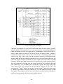
Fig. 4.3-1. List of interrupts present in H8S/263* series.
26
Independent interrupt vector address has big advantage, because in this case we don't have to
worry about identification of the source. All interrupts are controlled by the interrupt controller,
which has two control modes. The highest priority has NMI interrupt and this can not be
changed. To others interrupts we can assign eight priority levels. For external interrupts we can
detect falling, raising or both edges. This last is not true for NMI, where we can detect only
raising or falling edge.
In the following subsections we will focus mainly on IRQ and TPU interrupts. It is due to the fact
that in our Eurobot project we used only these two. Later, in the next chapter, the importance
of these will be shown when I'll try to explain how “index mark” detection in brushless motors
works with help of IRQ and how we used TPU interrupt for high frequency repeated procedures.
Let’s start with external interrupts IRQ0 to IRQ5. As we already mentioned these are external
interrupts and can be detected by raising, falling or both edges. What does it mean? The answer
is very easy. If we want to generate one or all of these interrupts we must physically connect
electrical lines (voltage/current sources) to proper pins. In this case these are: PORT12 for IRQ0,
PORT14 for IRQ1, PF0 for IRQ2, PF3 for IRQ3, P32 for IRQ4 and P35 for IRQ5. Of course this is not
everything. We also need to enable those interrupts using IER register. Here switching on and
off proper bits we can decide which interrupts should be enabled and which should stay
disabled. As I said at begin, it is possible to assign priority to these interrupts. We can do it very
easily using following registers: IPRA for IRQ0 and IRQ1, and IPRB for IRQ2, IRQ3, IRQ4 and IRQ5.
In this second case we see that unfortunately it is not possible to set up different priorities for
IRQ2 and IRQ3 and additionally IRQ4 and IRQ5. In other words, it means that IRQ2 and IRQ3 will
always have the same priority. The same limitation is for IRQ4 and IRQ5. To make detection of
edge, we need to set up properly two registers: ISCRH and ISCRL. Several pairs of two bits in
these two registers are responsible for selecting which kind of edge we want to detect through
proper interrupts. It is important to note, that always after finishing our interrupt routine we
need to clear proper bit in ISR register. Only this allows accept/detect new interrupt.
TPU is 16-bit timer pulse unit which can be regarded as special kind of internal interrupt.
H8S/2638 has 6 TPU channels – with numeration from 0 to 5. It can work in several different
ways: as normal counter compare match, input capture or phase counting (channels 1, 2, 4, 5)
and additionally in synchronous way. TPU can give different outputs: 0, 1, toggle or PWM. It is
also possible to set up buffer operation for channels 0 and 3. Going further we can connect two
channels for example 2 and 5 or 1 and 4 to work in cascade mode. Thanks that we can get one
or two 32-bit counters. To show the strongest side of this unit, we need to point out that there
is the total sum of 26 interrupt sources. This is thanks compare match, input capture, overflow
and underflow interrupt request. Although not all of these are possible for every channel,
making several combinations we can get powerful tool for motion control. To make it little bit
more clearly for a reader I'll try to shortly describe all of the channels.
27
Channels 0 and 3 are almost identical. This means both of them have the same interrupt
sources, the same number of general and buffer registers. Only one difference is with the
possibilities to set up the count clock. At this point I should mention that it is possible to count
clock's ticks in two different ways. First method is with use of internal clock. Here we have
several frequencies like: ф, ф /4, ф /16, ф /64, ф /256, ф /1024 and ф /4096. Second option is to
measure the ticks with a help of some external clock. These measurements we can do using
following pins: TCLKA, TCLKB, TCLKC and TCLKD.
Now, let’s back to our channels 0 and 3. In the channel 0 we can set up count clock for four
frequencies: ф, ф/4, ф/16, ф/64 or we can measure it with help of all above mentioned pins. At
the same time channel 3 can have count clock with frequencies: ф, ф/4, ф/16, ф/64, ф/256,
ф/1024, ф/4096 or we can count ticks on the TLCKA pin. Both channels have four general
registers, from which two can also work as buffer registers. They have also four I/O pins on
which we can detect different edges: rising, falling or both of them. This is useful option during
counter clear. Counter clear is possible through TGR register compare match or by input capture
with properties mentioned above. During the compare match, output can take two values: 0 or
1 or it can be toggled. The output can be also set as PWM in one of two modes. All of these we
can set up separately and independent for each channel. Of course it is also possible to make
configuration of these channels that they will work in synchronous way. Channels 0 and 3 can
not work in phase count mode. Last one, what is important for us, are interrupt sources.
Interrupts can come from four compare match or input capture from “registers/pins” TGIOA to
TGIOD and from TGI3A to TGI3D respectively for channel 0 and channel 3. It is also possible to
generate interrupt when the overflow occurs.
Channels 1, 2, 4 and 5 can all set up counter clock with frequencies: ф, ф /4, ф /16, ф /64 and it
is also possible to count external impulses with help of TCLKA. Additionally counter of channel 1
can have frequency: ф /256 and can use TCLKB. Channel 4 can have additional frequency for its
counter: ф /4 and can use TLCKC. Counter of channel 2 can be set up additionally with
frequency: ф /1024 and can use TCLKB and TCLKC. And at the end, channel 5 can have
additionally frequency for its counter clock: ф /256 and can use TCLKC and TCLKD. Above written
facts were the only differences between channels: 1, 2, 4 and 5. All next property like number of
general registers is the same for all channels and is equal to 2. All these channels have only two
I/O pins and counter clear can be done by TGR compare match or by input capture. In opposite
to channels 0 and 3, these can be set up to work in phase counting mode. The same as before,
they can have outputs with values: 0 or 1 or toggled. We can also use PWM output in one of two
modes. In addition it is possible to configure them to work in synchronous operation mode.
What is important, they can not provide buffer operations. Interrupts can be generated by
compare match or input capture on TGI1A and TGI1B for channel 1, TGI2A and TGI2B for
channel 2 and so one. Additionally it is possible to detect overflow and/or underflow and due to
its occurrence, generate interrupt.
28
In the following lines, I'm not going to go into details about several registers which are need to
be set up properly, but I'll try to shortly explain mentioned above buffer operation mode,
synchronous operation mode, phase counting mode and cascaded operation. It is important to
understand all of them in proper way if we want to fully use this microcontroller. I don't
describe PWM because in general it uses standard PWM approach and two available modes
differ only in details.
Let’s start with buffer operation mode. As pointed above, this mode is possibly only in channel 0
or 3. Switching on this option provides to situation in which TGRC and TGRD work as buffer
registers. The way how these two registers can be used depends on whether TGR works as
compare match or input capture. In the first situation, when a compare match occurs the value
in buffer register is transferred to the time general register. In the second situation, the value in
TGR is transferred to buffer register and at the same time the value in TGNT is transferred to
TGR.
Synchronous operation means that the values in a several TCNT counters can be cleared or
rewritten at the same time. This first operation we call synchronous clearing and second
synchronous presetting. Of course, in this mode, at begin we choose clearing operation for one
of the channels and then we set up other channels for synchronous cleari ng. The same we can
do for synchronous presetting.
Phase counting mode. This mode is little bit specific. Counter is incremented or decremented
according to differences in the phase of two external clocks connected to clock inputs pins for
channel 1, 2, 4 or 5. There are four different phase counting modes and they differ mostly on
how voltage levels should look like with regards to edges or eventually whether edges should be
rising or falling. Good graph examples for all methods are presented in documentation for
H8S/2638.
Cascaded operation is very easy to understand. In this mode we just virtually connect two
channels: 1 with 2 or 4 with 5. Thanks that, we get new 32-bit counter which consists from two
parts: lower and upper. Lower part is just counter from channel 2 or 5 and upper part is counter
from channel 1 or 4. In such configuration, upper part can be always incremented by overflow of
the lower part, and decremented by underflow of the lower part.
29
5. PXMC library.
5.1. Introduction.
PXMC is portable library to control various types of motors. Its main task or aim is to allow
user/developer to control different motors installed on different boards which can have also
different microcontrollers.
In more general we can say it is a multi platform code, initially written by Pavel Pisa for stepper
and brushless motors. Nowadays it can work for DC motors with IRC feedback, controlled by
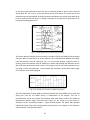
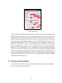
H8S/2638 microcontroller. The basic concept of PXMC is shown on the following picture:
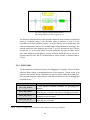
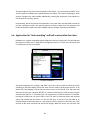
Fig. 5.1-1. The main concept of PXMC library.
A developer, who is represented here by a laptop icon, can use PXMC library to write programs
for different platforms and microcontrollers. At the some time he can choose interested motor
and then using proper functions and procedures he should be able to control different motors,
represented by car icons.
Of course in a real life, the above situation is not so easy. There are several conditions, which
must be fulfilled. First of them is, that there must exist a C/C++ compiler on the desired
30
platform. Secondly, developer must have at least some basic experience with motors and
microcontrollers. This is due to the fact, that there exist so many different motors, that it is
impossible to write support for all of them. Additionally, there will be always needed to make
some minor changes in the library's code, because on different hardware the connection will be
less or more different, because they depend mostly on the functionality of the board.
Next thing worth to understand is that the main purpose of the library was and still is to create
two layers. First should be a user friendly interface or API. Using this layer, user without deep
knowledge of hardware should be able to write pretty good and full functional application to
control all motors installed on the board. In this case, developer can have access only to small
number of functions and his only one concern is to set up properly all parameters in PXMC
structure. More about this structure I will write in next subsections. In general this layer will be
used in situation for example when we want to control our robot directly from the normal
computer using some program with graphical interface. The second layer is for more advanced
and experienced users. Here we can call all of the functions which are defined in PXMC library
and additionally create our own versions of them. This layer mostly will be used to write code to
support a new boards, microcontrollers and motors. Graphical representation of this description
was presented on the picture nr 5.1-2.
Fig. 5.1-2. Layers in PXMC library.
At the end I need to write one very important thing. PXMC library is still under development and
it is important to keep in mind, that some of the information included in this document can be
out of date it the moment when the reader reads it.
31
5.2. Preparation of the programming environment.
In this subsection I'll shortly present how to prepare programming environment for PXMC under
Linux operating system. Firstly, we need to download three packages:
binutils-2.16
gcc-3.4.3
newlib-1.14.0
All of above “programs” are under GPL license and can be free used even for commercial
purposes. The question which can arise at this moment is, why above packages are so old? For
example current (31.03.07) stable version of gcc is 4.1.2. The answer is very easy. It is possible to
compile all these packages without any problems. Personally I tried to do it also with binutils2.17, gcc-4.0.3 and/or gcc-4.1.1. Unfortunately I (and not only I) got errors, which concerned
capability. Namely the support for h8300-coff was removed in newer versions of GNU tool
chain. It is worth to note that h8300-elf is still supported and with small modification of below
steps it should be possible to create it.
When we already have all three above mentioned packages, we need to compile them. The
procedure in most steps is standard one. It means we use ./configure, make and make install.
Only one essential thing is that we need to set up proper switches when we call . /configure.
Because of that the right command ./configure for binutils looks like:
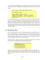
./configure --with-gnu-ld --target=h8300-coff\
--enable-shared
--enable-commonbfdlib \
--with-mmap \
--enable-64-bit-bfd
To proper configure gcc, first we need to unpack gcc and newlib, and after that we need to
create symbolic link from gcc to newlib:
ln -s newlib-1.14.0/newlib gcc-3.4.3/newlib
Then we write:
./configure --target=h8300-coff --with-gnu-ld \
--with-gnu-as \
--without-nls --with-newlib \
--enable-languages=c,c++ \
--enable-target-optspace \
--enable-version-specific-runtime-libs
32
When the configuration will be finished, we write in standard way: make and then make install.
As the result we will get binary file called: h8300-coff-gcc, which in this case is our desired
compiler for H8S/2638 microcontroller.
Next step is to get a copy of the PXMC library and to do it we need to have account on the
server. If it is like that, then we just need to type:
darcs get <login>@rtime.felk.cvut.cz:/var/repos/pxmc
Of course instead of <login> we should put our login name. Later we need to give our password
and we can download the library to our computer. As a small reminder, darcs is distributed
revision control system, which can be freely downloaded from: http://darcs.net.
5.3. Overview.
5.3.1. General overview of files.
When this document was created, the PXMC library consisted from 11 files:
pxmc.h
pxmc_base.c
pxmc_con_pid.c
pxmc_deb.c
pxmc_gen_info.h
pxmc_gen_spdtrp.c
pxmc_hh.c
pxmc_hh_basic.c
pxmc_inp_common.h
pxmc_internal.h
pxmc_ptable.c
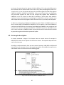
Additionally it had one subdirectory: board. In this subdirectory were three
subdirectories: h8eurobot, h8mirosot and hi_cpu2. The whole structure of the library and
its subdirectories is shown on the picture 5.3.1-1. It should be noted that in these
subdirectories are located hardware dependant files.
The whole structure with dependencies of PXMC files is shown on the picture nr 5.3.1-2.
Now we will look at each of these files separately and we will try to get at least some basic
concept about them.
33
Fig. 5.3.1-1. The structure of PXMC library.
Fig. 5.3.1-2. Files with dependencies in PXMC library.
34
5.3.2. General work of PXMC.
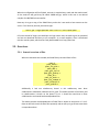
Before we go into descriptions of several files, which belong to PXMC library, we need to
get some information how PXMC is working in general. On the figure 5.3.2-1 we can see
the internal structure of PXMC and the most important variables and flags.
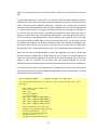
Fig. 5.3.2-1. Internal structure of PXMC.
So, let’s start with IRC. This component makes the measurements of the DC motor, which
later could be used by do_inp. Now, if the flag ENI (enable input) is enabled, do_inp
calculate the actual position (AP) and actual speed (AS). These two values are later used
by the controller (do_con). At the same time, if the flag ENG (enable generator) is
enabled, functions do_gen calculates request position (RP) and request speed (RS). As
before, also these two variables are used by the controller. Now, if flag ENR (enable
regulator) is enabled, the controller “takes” AP, AS, RP and RS and using P, D and I
constants calculates power (ENE). From last sentence we see that in this case the
controller is a PID type controller. When we have calculated power, we use function
do_out to combine it with proper values taken form a phase table(s) and send it to the
motor in a PWM form. Thanks that, the motor rotates little bit, IRC makes the
measurements and the whole situation repeats.
5.3.3. PXMC.H
Let’s start with the heart of PXMC library, namely pxmc.h. The most important thing
about this file is that we need to include it in all projects/programs in which we want to
use PXMC library. The importance of pxmc.h is that it defines pxmc_state_t structure,
which stores all needed information about motor(s) connected to our board. We also find
35
here definitions of all flags and definitions of the most functions which can be accessed
from PXMC. Now, lets try to look little bit more into details.
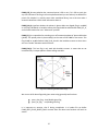
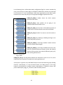
We start from flags. All of them, which are available in PXMC, are presented on the figure
nr 5.3.3-1, and in the following lines I'll try to introduce them.
The first, PXMS_ENI_b (Enable Input) enables input IRC
updates. It means that if this flag is set up, functions which
pointer is kept in pxms_do_inp will be executed.
PXMS_ENR_b (Enable Regulator) decides whether controller
and output will be switched on or not. If the flag is enabled
then functions are called which addresses are kept by
pxms_do_con and pxms_do_out.
PXMS_ENG_b (Enable Generator) is responsible for enabling
requested position generator. This flag and also two previous
are enabled according operation mode of the axis. This
mode can be like: feed forward, feedback and so one.
Whenever PXMS_ERR_b is set, it means that some error
occurred. If everything is working well this flag is disabled.
We can read error code from pxms_errno.
PXMS_BSY_b signalizes that axis/motor is busy. Because of
that calling some functions will result as error. For example it
is impossible to set new position with help of pxmc_go() –
this function will be described later in this subsection.
PXMS_DBG_b enables debugging. Unfortunately the
debugging functions are not full implemented for our
(brushless) motor and it is much better to use serial line to
debug and check the code than use this flag. Unfortunately,
using serial lines doesn’t really replace this functionality. This
is due to relatively low speed of serial line, whereas
brushless motor can rotate several hundreds times per
second.
Fig. 5.3.3-1. Flags in PXMC.
Enabled PXMS_CMV_b flag means that motor is working in group, so its movement
should be coordinated with other motors. This flag is used by standalone library which
uses PXMC as backend.
36
PXMS_CQF_b states whether the command queue is full or not. If it is full we can't give
any new command. This flag is still not implemented and you can find only its definition in
pxmc.h file. Maybe it is used by some other standalone library, but at the time when I
wrote this document I didn’t have information about it.
PXMS_PHA_b signalizes whether the phases in phase tables are aligned (flag is enabled)
or not (flag is disabled). In brushless motors this flag should be enabled after PXMS_PTI_b,
at the moment when we cross “index mark” position.
PXMS_PTI_b is responsible for switching on or off automatic updates of phase table index
(ptindx). The ptindx points in phase table(s) to the state of the PWM for the motor. This
flag should be enabled before PXMC_PHA_b and in the brushless motors we do it when
we cross “border” between two hall sensors.
PXMS_ENO_b. This last flag is only used with brushless motors. It states that we are
interested only in output updates without calling controller.
Fig. 5.3.3-2. Meaning of PHA and PTI flags.
We can use all of above flags with given names using generally two functions:
pxmc_clear_flag - clear/disable given flag
pxmc_set_flag - set/enable given flag
It is important to mention, that if during compilation in a header file we define
PXMC_WITH_FLAGS_BYBITS_ONLY constant then the above two functions will work as
atomic.
37
Let’s go further. If we want to check whether some flag is set or not, we need to check
pxms_flg. This is a bit field where the flags are stored in pxmc structure. Of course, in this
case, we can't use above names of flags, but we have to change the last letter from “b” to
“m”, for example: PXMS_ENI_m, PXMS_ENR_m and so one. This last need is due to the
fact, that one flag uses only one bit and if we want to spare memory, we can keep all of
them only in one byte or integer. Using this approach we need some way to
detect/establish which positions are occupied by different flags. Solution looks like this:
PXMS_ENI_b uses 1st bit, PXMS_ENR_b uses 2nd bit and so one. Now if we want to check if
PXMS_ENR_b is switch on, we need to shift it once to the left and then compare the state
of this bit with desired one. To avoid all shift operations and to make the program and
library more clear, in pxmc.h we have already defined all desired shifts correlated with
proper flag. They are also marked by letter “m” and can be used directly. In other words,
we can say that postfix “_b” means bit number and postfix “_m” means (bit) mask.
It is also good to note, that using this approach, we can enable or disable flag, without a
need to call pxmc_clear_flag or pxmc_set_flag. We can do it directly. For example, to
enable PXMS_ENI_b we can do this:
mcs->pxms_flg|= PXMS_ENI_m
And if we want to disable PXMS_ENI_b we do this:
mcs->pxms_flg&= ~PXMS_ENI_m
Finally to check if some flag is enabled we can do this:
(mcs->pxms_flg&PXMS_ENI_m)
The mcs in above examples is abbreviation of motor control structure and is a pointer to
pxmc_state structure, which describes our motor. We will keep the name of this pointer
in this way also in later sections of this document.
After describing flags, it's the highest time to go into details about pxmc_state structure.
Before we do it, we need to be familiar with couple of things. Firstly, as we will see some
of the values are shifted by PXMC_SUBDIV. This can be represented by the following
formula:
Where IRC is some value given in IRC units – explanation of IRC units is given in following
lines.
38
The advantage of the above equation is that it gives possibility to operate with help of
fixed point arithmetic, which increases controller precision and speed of calculations.
Secondly, as was already mentioned and shown in above formula, some values are given
in so called IRC units. Small example, we have phase table with length of 2048 elements
what is equal to 360o. To get 90o we need to divide 2048 by 4, and as the result we will get
512. This is 90o in IRC units.
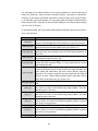
In the following table, there are shown and described all elements which can be found in
pxmc_state structure.
Name of pole
Short description
It was already mentioned in the part concerned with flags. Its only one
pxms_flg
function is to hold flags which have influence on control of the motor.
This is a pointer to a function which should read actual position and
pxms_do_inp
speed of the motor and then update pxms_ap and pxms_as.
This one keeps pointer to function which implements controller and
pxms_do_con
computes pxms_ene according to the actual and required position of
the motor.
This is also pointer to a function which puts proper output values to
pxms_do_out
the PWM with regards to pxms_ene.
This is a pointer to a debugging function which should store some
pxms_do_deb values and other important things. It is very useful when we testing
and checking the code.
Here is kept pointer to function which generates trajectory. This
trajectory describes how the motor should reach desired position with
given speed and acceleration. We have several different trajectory
pxms_do_gen
generators, for example: trapezoid, constant speed and also different
versions of them: normal and fine-grained. More information will be
given when I'll describe pxmc_gen_spdtrp.c file.
This is a pointer to function which presets a new actual position into
pxms_do_ap2hw
HW.
PXMC keeps here the actual position of the motor. The value which we
pxms_ap
can read or set must to be shifted using PXMC_SUBDIV. This value
should be given in IRC units.
PXMC keeps here the actual speed of the motor. The value which we
pxms_as
can read or set must to be shifted using PXMC_SUBDIV. This value
should be given in IRC units.
PXMC keeps here the required position of the motor. The value which
pxms_rp
we can read or set must to be shifted using PXMC_SUBDIV. In general
this value is set by generator.
pxms_rpfg
This is a position extension for Fine Grained generator.
PXMC keeps here the required speed of the motor. The value which
pxms_rs
we can read or set must to be shifted using PXMC_SUBDIV. In general
this value is set by generator.
pxms_rsfg
This is a speed extension for Fine Grained generator.
39
pxms_md
pxms_ms
pxms_ma
pxms_inp_info
pxms_out_info
pxms_ene
pxms_erc
pxms_p
pxms_i
pxms_d
pxms_s1
pxms_s2
pxms_me
pxms_foi
pxms_fod
pxms_tmp
pxms_ptirc
pxms_ptper
pxms_ptofs
pxms_ptshift
This field stores the maximal difference between actual and required
position. If the difference will be greater than this value, then error
will be generated: the flag PXMS_ERR will be enabled in pxms_flg and
the flag PXMS_E_MAXPD will be stored in pxms_errno. This value
should be given in IRC units.
This field stores the maximal speed of the motor. It has to be also
shifted using PXMC_SUBDIV. This value should be given in IRC units.
This field stores the maximal acceleration of the motor. This value
should be given in IRC units.
This is additional field is used by function showed by pxms_do_inp
pointer to select which IRC, position meter, etc. should be used.
This is also a special field which decides where function from
pxms_do_out should send energy stored under pxms_ene.
Under this variable is stored the value of energy (in fact it is power)
computed by the controller. The output function uses later this value
to combined/multiplied it with an output. As a result pxms_ene
decides how and in which direction to rotate the motor.
Here is stored the number of errors which occurred during the running
of the library.
Controller proportional constant, mainly used by PID controller which
functionality was incorporated in pxmc_pid_con.h file.
A/a, but with one exception, it is controller integration constant.
A/a, but with one exception, it is controller derivative constant.
This variable is a special constant for controller.
A/a.
Under this variable is stored a maximal value of pxms_ene. In Eurobot
project it is depended on CPU_SYS_HZ and PWM_HZ, which are
constants correlated respectively with the frequency of the
microcontroller and the frequency of PWM.
This pole is used by microcontroller for temporary computation of I.
A/a but it is for D.
Temporary variable for debugging
Value present here describes how long a phase table is.
This variable describes how many times we need to send all values
from the phase table(s) to get one mechanical rotation of the rotor. It
is used for motors with more electrical than mechanical rotations.
This is an offset between IRC and the beginning of the phase table(s).
This invariant always holds: 0 ≤ irc - pxms_ptofs ≤ pxms_ptirc, where
irc is an actual position returned by IRC. (See the picture nr 5.3.3-3).
This variable can be used to make correction when the motor is
rotating very fast. In other words, there can be problems with aligning
the magnetic field lines with 90o to the rotor. This is due to the fact
that controller’s computations take some time and if the motor
rotates very fast, then calculated direction of magnetic filed lines can
be not optimal (different from 90o) and out of time.
40
pxms_ptvang
pxms_ptindx
pxms_ptptr1
pxms_ptptr2
pxms_ptptr3
pxms_ptamp
pxms_pwm1cor
pxms_pwm2cor
pxms_pwm3cor
pxms_errno
pxms_cfg
pxms_ep
pxms_gen_st
pxms_gen_info
pxms_hal
This value is an angle between rotor and direction of magnetic field.
The optimal value for steeper motors is 0o and for brushless motors it
is 90o. It should be given using IRC units.
This is an index to phase table arrays, which shows which element
from the phase table should be send to PWM output. If the flag
PXMS_PTI_b is set, then this value is automatically updated by PXMC
library according to measured input from IRC. If it's not, we can put
here our own values, estimated for example from hall sensors.
This is a pointer to the 1st phase table. The number of phases depends
on the motor. For example brushless motors used in Eurobot project
had 3 phase tables.
A/about this pointer is for the 2nd phase table.
A/about this pointer is for the 3rd phase table.
This is the maximal value of phase table’s elements, called amplitude.
It is a correction field for PWM1 generator
It is a correction field for PWM2 generator
It is a correction field for PWM3 generator
This field keeps the number of last error which occurred when pxmc
was working.
This field has functionality to hold flags which describe the
configuration of a motor. See below description of possible flags.
This field is used by generator and it keeps the information about the
end position of movement and like pxms_ap or pxms_as is shifted
using PXMC_SUBDIV. This value should be given in IRC units.
This field describes the status of a generator.
This is a table of 8 elements, which are used by/for trajectory
generators and computations.
This field keeps last value read from hall sensor. Please see subsection
4.3.2 for more details.
Fig. 5.3.3-3. Meaning of ptofs.
41
In the following lines I will describe shortly configuration flags for a motor described by
pxms_state structure. All these flags are available in PXMC library and they are presented
on the picture nr 5.3.3-4. Unfortunately I didn't have opportunity to test them myself,
because in most cases they were just set by people with bigger experience than me.
PXMS_CFG_HDIR_b decides about the initial rotation
direction of the motor.
PXMS_CFG_HRI_b states whether we are going to use
revolution index from HP HEDS or not.
PXMS_CFG_HMC_b means that we find absolute position of
a mark center of a home direction axis with end switches.
PXMS_CFG_HLS_b decides if we want to use limit switch or
not.
PXMS_CFG_HPS_b: by enabling or disabling this flag we can
choose the polarity of switch.
PXMS_CFG_SMTH_b: If this flag is enables it means we want
to have a smooth speed changes.
PXMS_CFG_MD2E_b: If this flag is enabled, then every time
when the absolute difference between actual and required
position will be greater than maximal difference (pxms_md),
there will be generated error.
Fig. 5.3.3-4. Configuration
flags in PXMC.
PXMS_CFG_CYCL_b: This flag selects whether our axis/motor is cyclic or not. If it is, then
PXMC knows that overflow is intended and it won’t generate error.
At this point it is good to note, that PXMC library has some small and basic group of debug
functions. Unfortunately, as it was mentioned earlier, the debug section is still strong
limited in functionality for brushless motors. Nevertheless, it should be known, that
pxmc.h defines pxmc_dbg_hist_t structure, which has three pointers:
long *ptr;
long *buff;
long *end;
42
First one, *ptr is used to store information about speed and power sent to the output.
The*buff is used mainly to store a profile of speed generator. The *end pointer shows the
end of the buffer. Please see PXMC_DEB.C subsection to get little bit more information
about debugging.
Other very important thinks are error flags. We know from the table in point 5.3.3 that
pxms_state structure has field called pxms_errno, which keeps last error code. All error
flags are presented on the picture nr 5.3.3-5 and below is short description of them (the
value given after the name of a flag represents the hexadecimal code of the error):
PXMS_E_COMM - 0x105 – signalizes that the new index
position for phase table(s) is greater than the length of the
phase table(s).
PXMS_E_MAXPD – 0x106 – signalizes that the difference of
position is over limit. It means that absolute value of differenc
between pxms_ap and pxms_rp is greater than pxms_md.
PXMS_E_OVERL – 0x107 – signalizes that overload of
energy/power occurred. In other words, if the controller
function calculates new pxms_ene and it turns out to be
greater than pxms_me then this error occurs.
PXMS_E_HAL – 0x108 – signalizes that there was some
problem with reading of hall sensors.
Fig. 5.3.3-5. Error flags.
PXMS_E_POWER_STAGE – 0x109 – signalizes a power stage fault signal
At the end of the description of pxmc.h file, I want to give one very important note.
Namely, in every application which uses PXMC, we need to define one global variable
called: pxmc_main_list with a pxmc_state_list_t type. This structure consists from a list of
pxms_state structures (which describe motors) and the number of elements in this list.
The pxmc_main_list is in other words a total list of all motors which we want to use and
control in our program. It is mainly called from functions which provide some special
services and tasks for all motors. The small example how to create such list is present
here:
43
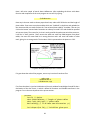
pxmc_state_t *pxmc_main_arr[] = {&mcsLeft};
pxmc_state_list_t pxmc_main_list = {
pxml_arr:pxmc_main_arr,
pxml_cnt:(sizeof(pxmc_main_arr)/sizeof(pxmc_main_arr[0]))
};
The “mcsLeft” was defined as pxmc_state_t.
5.3.4. PXMC_BASE.H
In this file there is defined so called “controllers general interface”, what is just the basic
functionality of the PXMC library. According to this, we have here such functions like:
Name of pole
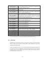
pxmc_set_const_out
pxmc_connect_controller_
prep*
pxmc_connect_controller
pxmc_set_gen_prep
pxmc_set_gen_smth
pxmc_go
pxmc_go_spdfg
pxmc_stop
pxmc_spd
pxmc_spdfg
pxmc_axis_set_pos
Short description
It sets a power to given value and keeps it constant. It is used for
feed forward control.
It prepares axis (motor) to a connection of a controller.
It connects a motor and a controller.
It prepares the motor to a new generator.
It smoothly changes the generator to a new one.
It moves the motor to a new given position. The movement has
trapezoidal profile.
It moves the motor to a new given position with selected speed.
As above, the movement has trapezoidal profile.
It stops the motor and this stop is done by a smooth slow down.
It starts a constant speed motion.
A/a but in this case it has fine-grained characteristic.
It allows setting new value for actual position for the motor.
* - function is not accessible from outside of the library
5.3.5. PXMC_CON_PID.C
This file defines only one function: pxmc_pid_con. This is an implementation of PID
controller which should calculate power (pxms_ene). This last value should be later taken
into account when we set the PWM output.
44
Fig. 5.3.5-1. General structure of PID controller.
PID used by PXMC can be seen on figure 5.3.2-1.
The efficiency and performance of PID controller depend on three constants: proportional
(pxms_p), integration (pxms_i) and derivative (pxms_d). Because of that it is very
important to set these variables properly. To do this without use of identification and
advanced mathematics, we can use so called Ziegler-Nichols Method of PID tuning2. This
method states that at the beginning we set the “I” and “D” constants to zero. Then we
increase the “P” to the point where we reach oscillations. This point is called “critical
gain”. Now taking the critical gain (K c) and the oscillation period (Op) we can set the “P”
constant equal to: 0.6 K c, the “D” constant equal to: 2*P/O p and the “I” constant equal to:
P*Op/8.
5.3.6. PXMC_DEB.C
This file implements some basic functions for debugging of a controller. The use of below
functions allows making a tuning/identification of the controller. To have access to all
functions listed below, during compilation we need to define PXMC_WITH_DBG_HIST.
One important thing we need to keep in mind. These functions are not for debugging of
the PXMC library!
Name of pole
pxmc_dbg_histfree
pxmc_dbg_histalloc
pxmc_dbg_ene_as
pxmc_dbg_gnr_gi*
2
Short description
It frees memory previously allocated for pxmc_dbg_hist_t
structure.
In opposite to above, this function allocates memory for
pxmc_dbg_hist_t structure, which stores debugging information.
This function stores in pxmc_dbg_hist_t structure the speed and
the power sent to the output.
It is responsible for storing the speed generator profile in
pxmc_dbg_hist_t structure.
Ref.: K. J. Ǻström , T. Hägglund “PID Controllers: Theory, Design, and Tuning”, 2nd Edition.
45
pxmc_dbg_gnr
pxmc_dbgset
This function is seen from outside of the PXMC library and in fact
it prepares all necessary elements for storing the speed
generator profile.
This function sets debugging options for a given motor.
Nowadays it is possible only to switch on or off debugging. It is
also possible to give as a parameter a pointer to a function for
debugging. This function sets PXMS_DBG_b flag automatically so
we don't need to worry about it.
*- function is not accessible from outside of the library.
5.3.7. PXMC_GEN_INFO.H
This is just header file, which defines several constants and fields for others functions.
These functions are later responsible for initialization generator(s).
5.3.8. PXMC_GEN_SPDTRP.C
This file contains mainly implementation of all generators which are available for a motor
control. Now, because a generator works as finite state machine, so it is possible to
represent it by a pointer to a functions which describe it. In other words we can imagine it
as a trapezoid, where at the beginning our pointer shows to a function which increases
speed. When the maximal speed will be reached then we automatically change the
pointer to function which will keep the speed as a constant. Then before we reach desired
position we change the pointer to another function which will slow down and finally will
stop our motor.
Name of pole
pxmc_add_cspdfg
pxmc_add_vspd
pxmc_set_spd
pxmc_set_spdfg
pxmc_spdfg_gnr
pxmc_spd_gacc
pxmc_nop_gd
pxmc_cont_gi
pxmc_trp_gi
pxmc_trp_spdfg_gi
Short description
Adds fine-grained speed to requested position.
Adds variable speed to requested position.
Sets new value of requested speed.
Sets new value of fine-grained speed.
Constant speed fine-grained generator.
Smooth transition to new requested speed.
No-operation generator state.
Initializes continuation generator. This type of generator is
temporarily used when new generator parameters are
computed.
Initializes trapezoid generator. This complex generator realizes
motion to requested end position with trapezoid speed profile.
Initializes fine-grained trapezoid generator.
46
pxmc_trp_gend
pxmc_trp_gend1*
pxmc_trp_gdu10*
pxmc_trp_gdu20*
pxmc_trp_gdu30*
pxmc_trp_gdd10*
pxmc_trp_gdd20*
pxmc_trp_gdd30*
pxmc_spd_gi
pxmc_spd_gd10*
pxmc_spd_gd20*
pxmc_spdnext_gi
pxmc_stop_gi
pxmc_spdnext_gd*
pxmc_spdnext_gend*
Changes request position to new factor, what should finalize the
use of trapezoid generator. This function is temporarily not
working due to pxms_gen_tep call.
Sets request speed to zero and than changes generator to
pxmc_nop_gd.
Increases request speed to maximal value and then it changes
generator to pxmc_trp_gdu20. This function is used when the
motor is rotating in upward direction.1
Keeps request speed as a constant and after some time it
switches generator to pxmc_trp_gdu30. Thanks that for example
trapezoidal shape can be achieved. This function is used when
the motor is rotating in upward direction. 1
Decreases request speed to zero and then it switches the
generator to pxmc_trp_gend. This function is used when the
motor is rotating in upward direction.1
It works as pxmc_trp_gdu10, but we use it when the motor is
rotating in downward direction. 1
It works as pxmc_trp_gdu20, but we use it when the motor is
rotating in downward direction. 1
It works as pxmc_trp_gdu30, but we use it when the motor is
rotating in downward direction. 1
Initializes constant speed generator.
Increases request speed and request position according to
acceleration and then it changes to pxmc_spd_gd20.
It adds the constant speed generator to a given motor.
Initializes transition to zero and then generator change.
Initializes transition to zero speed and then stop.
Changes the generator to new one.
Finalize changing of the generator.
* - function is not accessible from outside of the library.
1
. We can thing about it also in a manner of clockwise and counterclockwise rotation.
5.3.9. PXMC_HH.C
This file defines only one function: pxmc_hh. At this point I can't give to much information
about it. During my short period of learning PXMC, I didn't enough time to get some
experience about this function.
Anyway, according to the source file, it describes Hard Home finding and movement to
home position of the axis. In other words, first the motor goes to a first switch on the first
end then it goes to second switch at the second end. After that the home position is
calculated and the motor goes there.
47
5.3.10. PXMC_HH_BASIC.C
At begin of the description of this file, it should be clearly mentioned that this file has
couple of mistakes and probably it will not work properly. Moreover, because here are
calls to fields inside pxmc_state structure which don't exists, it seems that it should be
impossible to compile this file.
Name of pole
pxmc_hh_gi*
pxmc_hh_gd10*
pxmc_hh_gd20*
pxmc_get_hh_gi_4axis*
Short description
This function is responsible for “Hard Home” generator
initialization.
This is a one of the many versions of “Hard Home” generator.
A/a.
This function returns a pointer to the pxmc_hh_gi. This pointer
later can be used inside pxmc_state_t structure for
pxms_do_gen field.
* - function is not accessible from outside of the library.
The differences between pxmc_hh_gd10 and pxmc_hh_gd20 are mainly concerned with
changes in speed of the motor.
5.3.11. PXMC_INP_COMMON.H
This file implements two very important functions: pxmc_irc_16bit_update and
pxmc_irc_16bit_commindx.
Name of pole
pxmc_irc_16bit_update
pxmc_irc_16bit_commindx
Short description
This function updates PXMC fields: actual position and actual
speed, according to value read from 16bits IRC sensor. It
is/should be always called from function which pointer is stored
in pxms_do_inp.
This function is also called from function which pointer is stored
in pxms_do_inp, but only when the flag: PXMS_PTI_b is enabled.
We can say it is almost the heart of PXMS because it calculates
the new position of index in the phase table(s).
5.3.12. PXMC_INTERNAL.H
As we can see from the picture nr 5.3.1-2, it is one of the most important file in the whole
library. The importance of it is due to the fact, that it predefines several functions and
constants, later used by generators and/or by functions which operate on phase table(s).
48
In this subsection I will present only constants for run time phase table generation which
are defined in pxmc_internal.h. All functions which predefinitions can be found here will
be or already were described in above or below subsections.
PXMC_PTPROF_DEFAULT states that we are going to use a
standard or default phase table. The phase table has in this
case triangular shape.
PXMC_PTPROF_SIN decides that our phase table will have
sinusoidal shape.
PXMC_PTPROF_TRIANG. This flag informs that the shape of
phase table should be triangular. This shape is used also when
we use PXMC_PTPROF_DEFAULT flag.
PXMC_PTPROF_TRAPEZ states that the shape of the phase
table is trapezoidal.
PXMC_PTPROF_3PH. This flag informs that we are going to
use three phase tables with sinusoidal shape. In current state
this flag is the same as PXMC_PTPROF_SIN3PH.
PXMC_PTPROF_SIN3PH – a/a.
Fig. 5.3.12-1. Flags for
phase tables.
PXMC_PTPROF_SIN3FUP. By setting this flag we decide to use three phase tables with
sinusoidal shape. The only one difference between this and above, is that here we use
differences between the current minimal value from one of three phases and the other
phases. Thanks that, when we send some output to the PWM, one of the transistor is
always switch off. This allows reducing the losses of a current caused by transistor
switching.
5.3.13. PXMC_PTABLE.C
This file is highly correlated with described above pxmc_internal.h. Mostly it implements
all functions necessary to get proper phase tables which we can later use for a motor
rotation. Unfortunately, some microcontrollers don't have FPU. Due to this it is not very
good idea to use these functions directly, otherwise it can take some time to generate all
data. Great solution to this problem is to use below functions in some external program,
where we just generate the tables off-line. When we will have them, then we can add
49
them during compilation or linking. Exactly the same situation was with H8S/2638 which I
used.
Name of pole
pxmc_ptvang_deg2irc
pxmc_init_ptable_sin
pxmc_init_ptable_sin3ph
pxmc_init_ptable_sin3phup
pxmc_init_ptable_triang
pxmc_init_ptable_trapez
pxmc_init_ptable
Short description
This function converts phase shift from degrees to IRC units.
Mainly it is used to calculate properly pxms_ptvang in
pxmc_state structure.
It generates sinusoidal phase table for a given motor.
It generates sinusoidal 3-phase tables for a given motor.
It generates sinusoidal 3-phase tables for a given motor. In this
case we generate differences between minimal value of one
phase and nominal from other phases. Please see
PXMC_PTPROF_SIN3FUP in previous subsection.
It generates triangular phase table for a given motor.
It generates trapezoidal phase table for a given motor.
This function is responsible for initialization of phase tables.
Depending on profile given as a parameter it allocates memory
for phases and then it calls one of above described functions to
generate proper tables.
Fig. 5.3.13-1. Phase tables generated with
pxmc_init_ptable_sin.
Fig. 5.3.13-2. Phase tables generated with
pxmc_init_ptable_sin3ph.
50
Fig. 5.3.13-3. Phase tables generated with
pxmc_init_ptable_sin3fup.
Fig. 5.3.13-4. Phase tables generated with
pxmc_init_ptable_trapez.
Fig. 5.3.13-4. Phase tables generated with
pxmc_init_ptable_triang.
5.4. How to start work with the PXMC.
Nowadays, the way of starting to work z PXMC is quit simple and easy. Firstly, we need to
include to our project or application pxmc.h file and additionally pxmcbsp.h. First file gives us
access to all general PXMC functions. The second file can contain functions and/or other
elements or structures which are specific only for board which we are using to control some
motor.
After that, we need to create a pxmc_state_list_t pxmc_main_list list, as it was described in
subsection 5.3.3. This list contains the whole list of motors which we want to control with our
application.
The next basic step is to make initialization of the PXMC and the microcontroller. In general we
can do it very easily just by calling the function: pxmc_initialize(). In the case when we are using
51
bldctest for hi_cpu2 board we can also call function: pxmc_set_default_functions(pxmc_state_t
*mcs, pxmc_motor_kind_e motor). The first parameter is a pointer to a pxmc_state structure
which contains all necessary information about the motor. Second parameter is a value
describing which kind of the motor we are going to use in mcs. Thanks this function it shouldn’t
be a problem to have two kinds of motors connected to the board – for example one can be
brushless motor and second a stepper motor. Nevertheless, it should be kept in mind that in
normal case the recommended is always to use pxmc_initialize().
Fig. 5.4-1. Example of a DC motor which
can be also connected to the board.
Now, the last step is just to call some functions which are responsible for movement of the
motor. These functions can be for example: pxmc_go – which moves the motor to new position.
Another function is pxmc_spd, which is useful when we want to keep the motion with constant
speed. If the want to keep the power at the output at some constant value we can use:
pxmc_set_const_out. Whenever we want to stop the motor we can call pxmc_stop function. If
from some reason we want to set new actual and request position we can use the
pxmc_axis_set_pos function.
Additionally, for advanced usage we can connect some controller to the motor using function:
pxmc_connect_controller. To change generator we can use the following two functions:
pxmc_set_gen_prep and pxmc_set_gen_smth. First of them is used to prepare the motor to the
change of generator and second changes it in smooth way. It is important to note, that these
last two functions have to be called in the presented order. To check the sampling frequency we
can call pxmc_get_sfi_hz, and to make some changes in sampling frequency of PXMC subsystem
we should use: pxmc_sfi_sel. Additionally after defining the PXMC_WITH_DBG_HIST there are
also available some debug function for the motor: pxmc_dbgset, pxmc_dbg_gnr,
pxmc_dbg_ene_as,
pxmc_dbg_histalloc,
pxmc_dbg_histfree
and
pxmc_dbg_hist_t.
Unfortunately these function didn’t work fully for h8eurobot and hi_cpu2 board.
At the end, it should be clearly point out that all of above functions are described in subsection
from 5.3.3 to 5.3.13.
52
6. Adding Board Support Package (BSP) for BLDC on H8S/2638.
6.1. Introduction.
As was mentioned in section 5.1, the basic aim of PXMC library is/was to create easy to use and
extendable hardware independent code for motion control. At begin of my work with PXMC, the
situation looked quite different from above wishes. There was no separation of the code, no
modularity, and no external debug tool. The code was hard to understand and what is the worst
it was very hard to use. There was and still is a huge lack of a good documentation.
In the following subsections I'll try to present most of my work concerned with P XMC and all
changes which I made myself or with Michal Sojka's help/cooperation.
6.2. Subdirectories structure changes.
This subsection is strongly correlated with point 5.3.1 and the figure nr 5.3.1-1. As we can see on
this picture, that nowadays structure of subdirectories hardly depends on the target board. At
the early begin, it was totally different. All files were put together into one pxmc directory and
when we created some new application/driver, we had to create our new file and then include it
to our project.
Now the situation changed. Whenever we want to create a PXMC support to a new board (BSP –
Board Support Package), we just create new folder with the name of the board and then we
create the Makefile.omk with compilation rules for our BSP. In the Makefile.omk we also need
to set two variables at the beginning:
default_CONFIG = CONFIG_PXMC_VARIANT=default_variant
lib_LIBRARIES = pxmcbsp
Where the default_variant defines target board and motor configuration. Now, because BSP can
be compiled for different motors on different variant of board, we can use
CONFIG_PXMC_VARIANT to choose in which variant we are interested. If we want to compile
different than the default version, we can override this default value for example in config.omk
file.
Second line states in above that we just want to compile PXMC board support library. It means
that after we create our new .h and .c files, we only want to get a library as a result. In the case
when we just want to extend the already existed driver for a given board, we only need to add
new functionality in existing files.
53
Another improvement is that we decided to create one standard for all compilations. In other
words, now always when we compile PXMC we get two libraries:
pxmc
pxmcbsp
First of them has all “standard” and total hardware independent PXMC functions described in
point 5.3. Second library (PXMC Board Support) has our functions, which can be hardware
dependent and/or others functions which shouldn't be a part of standard PXMC library. Of
course to get right board support library, during compilation we need to set up mentioned
above CONFIG_PXMC_VARIANT variable properly.
After doing all above steps, we can very easily link both these libraries with any application just
by typing in Makefile.omk the following line:
program_name_LIBS =
pxmcbsp pxmc ...
Where the program_name should be changed to the real name of the program which we
compile and instead of “...” we can put others libraries needed by our program.
6.3. Changes in PXMC original code.
Working with Michal Sojka, we provided two small changes to original code of PXMC. First
change concerns pxms_struct. Namely we added here one field:
short pxms_hal;
/* last value read from HALL sensors */
This field has two basic aims. Firstly, it is very useful during detection of “index mark”, when we
need first to set PXMS_PTI_b and later PXMS_PHA_b flags. Secondly, it can have some useful
meaning to keep the actual value of a hall sensor.
Second change concerns error flags. Here we added two error flags:
PXMS_E_HAL
PXMS_E_POWER_STAGE
Because these two flags were already described in subsection 5.3.2 I'll not describe them here.
54
6.4. Work with hi_cpu2 board.
During getting experience with PXMC library I got one of the tasks to make hi_cpu2 board
working with brushless motors. This board has H8S/2638 microcontroller, which was described
in 3rd section. Thanks that it should be very easy to port most of the code to the robot, which
later was designed for Eurobot 2007 competition.
Fig. 6.4-1. Hi_cpu2 board.
The whole source code of driver which I wrote consists from two files:
bldctest.h
bldctest.c
The bldctest.h is just a header file in which are predefinitions for all functions accessible from
outside of the library. Additionally we can find here definition of CPU frequency in kilohertz:
PXMC_CYCLEKHZ and the maximum of power (pxms_ene): PXMC_PWM_PER.
The second file, bldctest.c, contains implementation of several functions listed in below table
and additionally it also initializes the pxms_state structure and array which keeps the hall sensor
table.
The implementation of hall sensor array is presented below. The table consists from 8 fields
from 0 to 7. The numbers in the brackets represent the values which can be read from hall
sensor. The numbers after the equality sign state in which 60 degree part is the motor. All values
presented here are taken from figure nr 3.5-4, except of 0xff. These represent the states which
are unachievable by the motor and if such value occurs on hall sensor, then there should be
generated error state.
55
const unsigned char
eurobot_bdc_hal_pos_table[8]=
{
[0]=0xff,
[5]=0, //1 0 1 = 5
[1]=1, //0 0 1 = 1
[3]=2, //0 1 1 = 3
[2]=3, //0 1 0 = 2
[6]=4, //1 1 0 = 6
[4]=5, //1 0 0 = 4
[7]=0xff,
};
Another mentioned structure was pxms_state. In this case I gave it the name mcs_left and
theoretically it should represent the left motor. As the default I assumed that the position of the
motor should be automatically updated – flag PXMS_ENI_m. Functions for input, output,
controller and hardware update are standard one. The maximal difference between the actual
and requested position was set up to the half of IRC value during one rotation. Maximal speed
was chosen arbitrary to 100, and maximal acceleration to 1. The addresses for input and output
information were chosen according to selected TPU and PWM registers. P, I and D constants
were selected after small tuning and should be enough for normal work of the motor. Maximum
energy is calculated by formula represented by following equation:
CPU_SYS_HZ/PXMC_HZ
Where: CPU_SYS_HZ is CPU frequency (it is defined in system system_def.h file). PXMC_HZ
represents the sampling frequency in which PXMC should work and it is given in Hz. Values of
pxms_ptirc, pxms_ptper depends on chosen phase table. In this case it was 2048 and 1
respectively. The last important things about this configuration are configuration flags. Here I
decided that the motor should generate error always whenever the absolute difference
between actual and requested position will be greater then pxms_md. Additionally, the
controller uses limited switch, we should have the possibility to chose polarity of the switch, the
initial rotation should be clockwise and all transitions should be smooth.
pxmc_state_t mcs_left={
pxms_flg:PXMS_ENI_m,
pxms_do_inp:motor_do_input,
pxms_do_out:motor_do_output,
pxms_do_con:pxmc_pid_con,
pxms_do_ap2hw: tpu_irc_ap2hw,
pxms_md:131074<<8, pxms_ms:100, pxms_ma:1,
pxms_inp_info:(long)TPU_TCNT1, /*chanel TPU A,B*/
pxms_out_info:(long)PWM_PWBFR1A, /*chanel PWM A,B*/
pxms_ene:0,
pxms_p: 100, pxms_i: 20, pxms_d: 100, pxms_s1: 0, pxms_s2:
0,
56
pxms_me:PWM_MAX<<8, //6144
pxms_ptirc:bldc_ptirc, // IRC count per phase table
pxms_ptper:bldc_ptper, // Number of periods per table
pxms_ptshift:0, // Shift of generated phase curves
pxms_ptvang:bldc_ptirc/4, // Angle (in irc) between rotor
and stator mag. fld.
pxms_ptptr1:bldc_phase1,
pxms_ptptr2:bldc_phase2,
pxms_ptptr3:bldc_phase3,
pxms_ptamp:0x7fff,
pxms_hal: 0x40,
pxms_cfg:PXMS_CFG_MD2E_m | PXMS_CFG_HLS_m |
PXMS_CFG_HPS_m | PXMS_CFG_HDIR_m| PXMS_CFG_SMTH_m| 0x1
};
In below table there is a full list of all functions which were written or created by my. One
exception is tpu_irc_ap2hw, which was taken from previous versions of the library.
Name of pole
Short description
This function makes full initialization of the board, including:
pxmc_initialize
PWMA, IRQ, HALs and TPU. We should always call this
function as first in external applications.
Because hi_cpu2 board can also work with stepper motor, so
this function allows us to make initialization of the all
pxmc_set_default_functions_for_
connected motors different than default brushless motor.
all_motors
Initialization depends on the given parameter, which
describes if it is brushless or stepper motor.
This function makes initialization of given motor according to
pxmc_set_default_functions
given parameter, which describes if it is brushless or stepper
motor.
This function is interrupt service routine and is always called
when in TPU compare match occurs (once per sampling
pxmc_sfi_isr*
period). The function calls later specialized routines for input,
output and so one. Please see below.
This is specialized function is called during interrupt. In
general it calls function which pointer is shown by
interupt_input*
pxms_do_inp and due to this it is responsible for actualizing
the actual position and speed of the motor.
A/a, but it calls functions which are pointed by: pxms_do_con
interupt_controller_and_output*
and pxms_do_out.
A/a, but it is responsible for calling generator pointed by:
interupt_generator*
pxms_do_gen.
57
interupt_dbg*
index_mark_isr_1*
index_mark_isr*
init_pwm*
init_irc*
init_hal*
init_sampling*
set_irq*
motor_do_input*
motor_do_output*
A/a. This routine is called in debug mode to store some debug
information about the motor. The pointer to debug function
is stored in: pxms_do_deb.
This function sets up PXMS_PHA_b flag when the “index
mark” will be detected. Because it is interrupt routine, it is
switched off after above flag is set up. Detection of “index
mark” is done by TPU. It can be use only once.
This function works exactly as previous one. The only
difference is that this is called by IRQ. It can be use only once.
Makes the initialization of PWM.
Makes initialization of IRC.
Initializes hall sensors.
Initializes TPU and sets up the main interrupt routine to
pxmc_sfi_isr.
Initializes IRQ to detect “index mark”.
This function should be pointed by pxms_do_inp. It is
responsible for updating the state information like actual
position and speed.
This function should be pointed by pxms_do_out and
according to PXMS_PTI_b and PXMS_PHA_b flags it calculates
or not the actual value of pxms_ptindx. Next, it takes the
power from pxms_ene and sends proper values to PWM
outputs.
* - function is not accessible from outside of the library.
Additionally in the hi_cpu2 directory can be found these files:
pt2000.h
pt2048.h
pt4000.h
pt.c
pxmc_config_h8mirosot.h
Makefile
Makefile.omk
First three files: pt2000.h, pt2048.h and pt4000.h have definition of phase tables for motors
which need 2000, 2048 or 4000 number of periods.
The pt.c file imports right phase table and adds it to the project.
The pxmc_config_h8mirosot.h was written by the authors of the board and has some definitions
which are used during compilation.
58
Last two files: Makefile and Makefile.omk have descriptions of the rules for compilation and are
used by make command. In Makefile.omk we should list all files which we use in our driver. For
example:
default_CONFIG = CONFIG_PXMC_VARIANT=bldctest
lib_LIBRARIES = pxmcbsp
pxmcbsp_SOURCES = bldctest.c pt.c
renamed_include_HEADERS += bldctest.h->pxmcbsp.h
renamed_include_HEADERS += pxmc_config_h8mirosot.h>pxmc_config.h
First line describes the variant of the compilation and as an option was described in subsection
6.2. The same is with lib_LIBRARIES. In pxmcbsp_SOURCES we list all source files which are
needed by our driver. In this case we use bldctest.c and pt.c. Next lines which define:
renamed_include_HEADERS informs that we are going to change the names of header files to
some standard one. Thanks that, later in some external project we can just include pxmcbsp.h,
what gives us opportunity to compile one application for different platforms without making
changes in the code.
6.5. Work with Eurobot.
My work with Eurobot was very closely correlated with work with hi_cpu2 board. Because of
that, all changes described in previous subsection are also valid for this point. Only one
difference is that in Eurobot we used different parameters for PID controller and also phase
tables were different. Namely, in this case we used phase tables with length equal to 2000 (for
motors on the robot) and 4000 (for motors used for testing).
Another work, which I made for this project, was to design some odometry for the robot. My
original solution was created in Matlab and can be described as below:
alfa=alfa+((vl-vr)*dt*O)/l; % [rad]
alfa=mod(alfa,2*pi);
xl=xl+vl*O*dt*sin(alfa);
yl=yl+vl*O*dt*cos(alfa);
xr=xr+vr*O*dt*sin(alfa);
yr=yr+vr*O*dt*cos(alfa);
Where: O - perimeter of the wheel, l – distance between two wheels, dt – difference in time
between two measurements, vl – speed of the left wheel, vr – speed of the right wheel, alfa –
angle in which robot is pointed, xl – new position of the wheel, xr – new position of the right
wheel.
59
The general idea is that, if we know the speeds of the wheels – we can read it from PXMC – then
we can calculate the difference in speed between two wheels. This allows calculating by which
amount in degrees the robot rotated. Additionally, knowing the perimeters of the wheels we
can calculate how far they “drove”.
Unfortunately, due to fact that the microcontroller is very slow and it was impossible to make all
of these calculations within one interrupt period, we had to resign from this approach and
finally we decided to send to the main computer only the changes in position of the wheels.
6.6. Application for “index marking” and hall sensors table detection.
HalDetector is a special purposed program designed to detect the right order of a hall table and
the position of “index mark”. Application was originally written in C++ with use of QT library and
it should work on every Linux system.
Fig. 6.6-1. HalDetector.
The general algorithm for creating a hall table is very easy. We just need to rotate the motor
according to the phase table(s) and at the same time we need to check the hall sensors. If we
detect that they changed, it means that the motor enters to the next 60o part. We know that
there are six such parts – because 360o/60o =6. If we have 3 hall sensors it also means we can get
maximal value equal to: 7 - all sensors give 1 so we get binary: 111 what is equal to 7 in decimal.
Knowing all of these we can start to work. Firstly, we start to rotate the motor and read hall
sensor. We assume that the motor is in the first 60o part, so we put in the hall table in an
element shown by hall sensor value 0 – zero because in C/C++ mostly we count from zero. Then
we wait till the value read from hall sensors will change. When this occurs, we put to the hall
60
table in an element shown by hall value the number 1 and so on, till we rotate the motor by
360o.
If it goes about detection of “index mark”, the situation is little bit more complicated. Namely
position of the index mark is strict and its detection should be very accurate. To achieve this we
need to use little bit more advanced technology – interrupt. This is mostly due to fact that
interrupts work almost immediately. We have two possibilities: we can use TPU or IRQ to detect
it. To make it more clearly in my program I decided to use IRQ, but it shouldn’t be a problem to
use TPU. All the rules are the same. Let’s look now how does it work. When the motor is
rotating, it crosses index mark. This generates IRQ interrupt. In the interrupt function there is
only an increment of one global variable. When we detect this increment and we know the
actual value of index for phase table, we can say where the index mark is. At this point it should
be noted that we should be very careful by detection of index mark. Namely, at the beginning of
the rotation there could be such position of the rotor, that the motor will cross index mark
giving wrong results – please see the picture nr 6.6-2 and its description later in this subsection.
Before we look into the implementation of above two algorithms, we need to know what
command processor (CMD_Proc) is. About CMD_Proc we can think as a terminal program to
control the other executed program. In a normal case this terminal program has to be run by
typing its name on a terminal. On the other hand, this terminal program can be also
used/executed by some other program. For more information please look to the 7.2 subsection.
Let’s look now at the code. For the proper work of HalDetector we need to create one special
command processor function and one global variable inside our driver for the motor. The body
of this function is presented below:
short index_marking=0;
// global variable for index mark
int cmd_do_detection(cmd_io_t *cmd_io, const struct cmd_des *des, char
*param[])
{
pxmc_state_t *mcs = &mcs_left;
short hal=0x00;
char *snd;
index_marking%=4;
// stop the motor
pxmc_clear_flag(mcs,PXMS_ENR_b);
pxmc_clear_flag(mcs,PXMS_ENO_b);
pxmc_clear_flag(mcs,PXMS_PHA_b);
pxmc_clear_flag(mcs,PXMS_PTI_b);
short ene=1024;//mcs->pxms_ene;
unsigned long pwm1=atol(param[1]);
snd=strchr(param[1],':')+1;
unsigned long pwm2=atol(snd);
snd=strchr(snd,':')+1;
unsigned long pwm3=atol(snd);
61
snd=strchr(snd,':')+1;
int whichIDX=atoi(snd);
if(whichIDX<0)
{
pwm1 = (((unsigned long)pwm1*(unsigned int)ene) >> (15+5));
pwm2 = (((unsigned long)pwm2*(unsigned int)ene) >> (15+5));
pwm3 = (((unsigned long)pwm3*(unsigned int)ene) >> (15+5));
}
else
{
whichIDX%=mcs->pxms_ptirc;
pwm1 = (((unsigned long)mcs->pxms_ptptr1[whichIDX]*(unsigned
int)ene) >> (15+5));
pwm2 = (((unsigned long)mcs->pxms_ptptr2[whichIDX]*(unsigned
int)ene) >> (15+5));
pwm3 = (((unsigned long)mcs->pxms_ptptr3[whichIDX]*(unsigned
int)ene) >> (15+5));
}
*PWM_PWBFR1A = pwm1;
*PWM_PWBFR1C = pwm2;
*PWM_PWBFR1E = pwm3;
hal=(*DIO_PORTJ>>3)&0x07;
printf("PHA:%2d HAL:%2d\n",index_marking,hal);
return 0;
}
The global variable index_marking is used by interrupt routine during index mark detection. The
interrupt just increases the value of this variable. The function cmd_do_detection requires four
parameters and it can work in two different ways. If the last parameter is lower than 0, the
function takes three first arguments and uses them as values taken from phase tables. In this
case, these phase tables are generated by the HalDetector program. Of course we need to
remember that these values will be later multiplied by power (pxms_ene), in this case arbitrary
chosen as 1024. Secondly, if the fourth parameter is greater or equal to zero it means that it is
an index of the phase tables which are already included in the driver. In this case first three
arguments are ignored. Below is “formalized” presentation of the function:
detection PWM1:PWM2:PWM3:INDEX
And here is some small example how to call cmd_do_detection:
detection 10:20:0:-1
62
Now I will write couple of words about HalDetector. After uploading the driver with above
function and compilation of the main program we can call it by typing:
./haldetector
Next step is that we need to choose proper band rate, node to RS-232 device and the length of
phase tables. If we want to use phase tables which are “included” to the driver and uploaded to
the microcontroller, we need to select the “Use on board phase table(s) ” checkbox. Then we just
click on the button start and wait. Detection can take up to round 5 min and should be repeated
at least two times. The reason for it is that it can by possible that when we switch the motor on,
it will be in “bad” position. “Bad” means that when we send first PWM outputs from phase
tables, the rotor will rotate little bit in wrong direction and it will cross hall border or index
mark, giving rise to wrong results. The situation of this is presented on the picture nr 6.6-2.
Fig.6.6-2. Wrong direction of the rotor's rotation.
If it goes about the code of the program, we can say it consists from three files:
main.cpp
haldetector.h
haldetector.cpp
First from the above is just the initialization of the main window frame/widget. Second file has a
declaration of the class Form1, in which I defined all functions and variables used later in the
program. For us the most important is the private section:
private:
int fd; // device
short phaseTableLen; // length of phase tables
short *ph1,*ph2,*ph3; // phase table
bool working; // if we make some discoveries ;o)
int initport(int fd); // initialize given port
63
int
int
int
int
int
int
int
int
writeport(int fd, char *chars);
readport(int fd, char *result);
getbaud(int fd);
allocateMemory();
deallocateMemory();
openDevice();
closeDevice();
generatePhaseTables();
int detection(short pos_pha[], \
short *nr_of_pha,\
unsigned short hal_tab[]);
Now, fd is just a file descriptor of the device which is used to the serial communication. The
variable phaseTableLen keeps the value taken from the “Phase table len.” text field, which is
visible on the picture 6.6-1, and it decides how long our phase tables should be. Next variables
ph1, ph2 and ph3 are just pointers to generated phase tables. The variable working is used to
check whether we are doing now some detection or not. The function initport 3makes
initialization of the serial port according to the given parameters. The functions writeport2 and
readport2 are used to respectively send and get some message to/from the serial port. The
function getbaud2 reads the baud rate used in the transmission. The function allocateMemory,
as it names states, allocates memory for phase tables. The deallocateMemory makes opposite to
previous function. It releases allocated memory for phase tables. The functions openDevice and
closeDevice respectively open and close serial port for communication. The next one is:
generatePhaseTable and it only generates phase tables exactly in the same manner as
pxmc_init_ptable_sin3phup described in subsection: 5.3.12. The last function: detection(…) is
used to call command processor directive: detection, and then to work in proper manner with
results which it returns.
3
These functions come from http://www.captain.at/electronics/pic-mmc/. (c) 2004-5 Captain
64
7. Testing and documentation of the code.
7.1. Introduction.
The testing and debugging of the code were not easy tasks. This was mostly due to the lack of
good debugger and debugging functions for brushless motor. Fortunately there was one
solution to this problem. Namely, it is possible to send commands and get responses from the
microcontroller using serial line and tools like: gtkterm. The use of serial line is described in the
next subsection.
Another task was to write and generate the documentation. In this case, the descriptions of the
all functions and the code were made in “standard” way, according to Kernel Doc, which is used
for documentation of Linux Kernel Sources. Thanks that it was possible to use standard tools to
generate documentation in HTML format. Please see the 7.3 subsection to get little bit more
details about it.
7.2. Command processor (CMD_Proc) and serial line.
To use serial line RS-232 we need to include this file:
periph/sci_rs232.h
It contains definitions of functions which allow the serial line communication on H8S/2638. For
example to initialize serial port we need to write such line in our program:
sci_rs232_setmode(19200, 0, 0, sci_rs232_chan_default);
Now, to use command processor, we need to include the following two files:
cmd_proc.h
cmd_pxmc.h
First one is system file, which describes all structures uses by CMD and is just a general
command processor file. Second file contains the definitions of several standard PXMC
commands.
Let’s look now how we can create some function to display popular “Hello world!”. This can be
done in very easy way. Here is some example:
65
int cmd_do_something(cmd_io_t *cmd_io, const struct cmd_des
*des, char *param[])
{
printf("Hello world!\n");
return 0;
}
Then we create its description by adding following line:
cmd_des_t const cmd_des_something={0, 0,"SOMETHING","do some
command", cmd_do_something,{(char*)&cmd_list}};
And at the end we must add it to the command list. We can do it very easily by typing:
cmd_des_t const
*cmd_list_default[]={
&cmd_des_something,
NULL
};
Of course we can place here several others function.
Now, inside main loop in the program we need to place this line:
cmd_processor_run(&cmd_io_rs232_line, cmd_list_default);
This just runs the command processor, which read characters from serial line and if the line is
finished it executes the function “attached” to recognized command. It is good to know, that
this function is non-blocking, so if there are no characters, it doesn’t wait for them. The
cmd_processor_run(…) has to be repeated several times and because of that it should be always
placed in some loop. That's all. Now we only have to set up some RS-232 connection to our
board and we can send there command: SOMETHING and this should do our new function.
As the final word of this subsection should be that due to lack of good debugging tool, it is still
possible to make pretty good testing and checking of the code with help of serial line. For
example, during preparation of the working brushless motor for Eurobot, we created several
testing functions in above manner. Then, by displaying different values and variables we were
able to localize several errors and mistakes. Of course this approach costs a lot of time but in
current state of the PXMC it is the only one good solution for developer.
66
7.3. Documentation.
Documentation for bldctest.c and for bldc.c was generated automatically with help of script
written in Perl, called: kernel-doc4. Exactly the same script is used to generate the
documentation for kernel sources and because of that there are couples of rules which are
important to keep in mind during creation of documentation.
Firstly, if we want to describe some function, we can do it in the following way:
/**
* name_of_the_function – short description of the function which we describe
* @some_arg: here is description of this argument
*
* Here can be some longer explanation of the function.
*
* Example:
* name_of_the_function(1);
*/
The keyword Example: states that we want to put some example how to call function.
Whenever we want to describe structure, union, enum or typedef before its name we need to
write the type of definition: struct/union/enum/typedef. Here is small example:
/**
* struct some_structure - short description
* @a: first member
* @b: second member
*
* Here can be some longer explanation of the
structure.
*/
struct some_ structure {
char a;
long b;
};
Additionally it is possible to mark some other elements like: environmental variables,
constants... The full list was taken from examples in the script and is shown below:
4
This script can be downloaded from: http://kernel.org/pub/linux/kernel/people/marcelo/linux-2.4/scripts/kerneldoc
67
'funcname()' - function
'$ENVVAR' - environmental variable
'&struct_name' - name of a structure (up to two words
including 'struct')
'@parameter' - name of a parameter
'%CONST' - name of a constant.
Finally when the description will be finished, we just type:
./kernel-doc -html somefile.c > output.html
In this way we can generate different kinds of documentation: html, docbook, text or man. The
documentation of bldctest.c and bldc.c are attached in Appendix A.
Additionally the documentation attached in Appendix B for HalDetector program was created
using Doxygen 1.5.2. The chose of this doc program was mostly due to the fact, that it can be
very easily integrated with KDevelop. Additionally it has several different output possibilities like
for example: html, latex, rtf, man, xml and others.
Because of variety possibilities for making documentation – different styles and many
commands, I decided not to write here examples like for kernel-doc. Nevertheless, for all who
are interested in details of Doxygen, there is a good manual free available on the homepage of
the project. The manual has a plenty of examples for each command with resulting outputs.
68
8. Conclusions.
The general conclusions from my work are not simple task, so I think the best would be if I present
my own opinion about every part or element on which I gained some new experience.
Firstly, my knowledge about motors was/is not too big, but personally I think that brushless DC
motors represent one of the most powerful and useful group of motors. At the first look, the control
of this kind of the motors seems very hard and complicated task - especially when we compare it to
a normal DC motor, where it is just enough to connect power to make it working. But, at the same
time this “complication” gives us much more possibilities, starting from a silent during operation,
and finishing at higher accuracies in changes of the speed. Additional support in manner of hall
sensors and index mark allows us to create devices where we are mostly interested in high accuracy
and precision – for example in space technology or military. The confirmation of all above can be
found in Mars Robots – Spirit and Opportunity - which also base on Brushless Motors.
Another device which allows me to get new experience was H8S/2638 microcontroller. My final
opinion about it is also very positive. Although the calculation power of it is comparable with
microprocessors from middle 80’s, but at the same time some futures like: PWM Timer, TPU,
Watchdog, support for CAN, high number of I/O ports, exception handlings and many others make
this microcontroller very useful for control of Brushless Motors (and not only brushless). Of curse
there are also some drawbacks. First is a lack of some software simulator of it. If there would exist
some similar tool like AVR Studio for ATmega128 microcontroller, the speed of creating and testing
programs for H8S/2638 would highly increase. Second, there is missing FPU (floating point unit). This
can lead to a situation, when we need some external computer to make more complicated
calculation. For example, it is almost impossible to use only H8S/2638 for full autonomous
odometry.
Finally, here are a couple of words about PXMC library. Now, after several hours spending on
working on it, I really like it. PXMC has a strong potential to become one of the best library for
motor control. The one big problem is a lack of a good and actual documentation. Because of that,
for the beginners, going through and analyzing the code is like trip through the jungle (hopefully
there are some guiders ;)). Except this drawback, there are a plenty of positive aspects. I will present
only couple of them. Firstly, if someone has some experience with it, it is really very easy for him to
extend the library and add support for new devices. Secondly, the concept of BSP (Board Support
Package) brings high simplification of the use of code for supported boards and motors. Thirdly,
because PXMC is written in C, it is very easy to increase its performance and speed by adding some
assembler parts. Finally, because this library is under GPL license, everyone can use it for free even
for commercial purposes. One thing worth to note is a need of simulator. As far as I spoke with
Michal Sojka, there is a plan to create some simulator of PXMC. Personally, I think that now it should
be one of the priorities for PXMC. Having such simulator would allow to spread this code among
different users than students. This potentially new programmer and developers probably, even
69
without having a contact with the authors, could very easy learn and test different properties of
PXMC. It would also allow for better understanding of different components and functions which
are or will be implemented in the library.
Fig. 8-1. The full configuration of hi_cpu2 board and
Connected brushless motor.
At the end I would like to underline, that the whole work which I made for this thesis brought me
really a lot of fun and new experience, which I hope to use in the future.
Fig. 8-2. Motor mounted in Eurobot Robot.
70
9. Sources.
(1) Renesans Technology - “H8S/2639, H8S/2638,H8S/2636, H8S/2630, H8S/2635 Group Hardware
Manual” *online+
URL: http://documentation.renesas.com/eng/products/mpumcu/rej09b0103_h8s2639.pdf
(2) Maxon - Maxon EC motor catalog and documentation
URL: http://pdf.directindustry.de
(3) Parker Motion&Control – “Brushless Motors – Engineering Reference”
URL: http://www.parkermotion.com/catalog/catalogA/SectionA.pdf
(4) Isabelle Rieucros - “PXMC Documentation”
(5) Online Encyclopedia Wikipedia
URL: http://www.wikipedia.org
(6) Michigan Mars Rover Team - “Expert Summaries of Chassis Technologies”
URL: http://marsrover.engin.umich.edu/RASC-AL/Expert_Summaries.pdf
(7) Digital encoders
URL: http://mechatronics.mech.northwestern.edu/design_ref/sensors/encoders.html
(8) URL: http://www.captain.at/electronics/pic-mmc/
(9) Doxygen
URL: http://www.stack.nl/~dimitri/doxygen/index.html
(10)Several hours cut from my life and spent on analyzing, testing and writing different programs and
functions...
71
Appendix A
Here is presented the whole documentation for the PXMC source code files, which were created during
my work on this thesis. All of below functions and description were copied directly form html files
generated by ./kernel-doc tool.
A.1 The documentation for bldctest.h:
enum _MOTOR_KIND_
enum _MOTOR_KIND_ {
pxmc_m_stepper,
pxmc_m_brushless,
pxmc_m_test
};
Constants
pxmc_m_stepper
stepper motor
pxmc_m_brushless
brushless motor
pxmc_m_test
for tests
Description
This defines kinds of motors which are or could be connected to the board.
typedef pxmc_motor_kind_e
typedef pxmc_motor_kind_e
Description
This defines new type: pxmc_motor_kind_e type as _MOTOR_KIND_.
72
Function
unsigned char hal_read (struct pxmc_state * mcs)
Arguments
mcs
Motion controller state information
Description
This function reads and returns hall sensor value.
A.2 The documentation for bldctest.c:
Function
int pxmc_initialize ( void)
Arguments
void
no arguments
Description
This function initializes all subsystems necessary for proper work of pxmc. There are switched
on: pwm, hall sensors read, irc updates, sampling period is set up and the irq for index mark
detection.
Function
bool pxmc_set_default_functions_for_all_motors (pxmc_motor_kind_e motor)
Arguments
motor
Kind of motor which we are going to use -> see header for full list of supported motors
Description
This function sets up defaults pointers to control functions for all motors which are presented in
the system. The default configuration depends on the motor kind.
73
Function
bool pxmc_set_default_functions (pxmc_state_t * mcs, pxmc_motor_kind_e motor)
Arguments
mcs
Motion controller state information
motor
Kind of motor which we are going to use -> see header for full list of supported motors
Description
This function sets up defaults pointers to control functions for a given motor. The default
configuration depends on the motor kind.
Function
void pxmc_sfi_isr ( void)
Arguments
void
no arguments
Description
This interrupt service routine is used to call routines for different services, like pxms_do_inp,
pxms_do_out and so one. It also updates the pxmc_msec_counter. It works according to
interrupts and is called with freq. equal to pxmc_sfikhz. Function is set in interrupt vector table
by: init_sampling function.
Function
void interupt_input ()
Arguments
Description
The function is used to call pxms_do_inp functions for all motors present on the board. It's called
by pxmc_sfi_isr during every sampling period.
74
Function
void interupt_controller_and_output ()
Arguments
Description
The function is used to call pxms_do_con and pxms_do_out functions for all motors present on
the board. It's called by pxmc_sfi_isr during every sampling period.
Function
void interupt_generator ()
Arguments
Description
The function is used to call pxms_do_gen functions for all motors present on the board. It's called
by pxmc_sfi_isr during every sampling period.
Function
void interupt_dbg ()
Arguments
Description
The function used to call pxms_do_deb functions for all motors present on the board. It's called
by pxmc_sfi_isr during every sampling period.
Function
void index_mark_isr_1 ( void)
Arguments
void
no arguments
Description
This interrupt routine is used to set up PXMS_PHA_b flag for the first motor on index mark
detection. Function uses TPU for index mark detection. In general the function should work in
such manner, that it switch off itself when the second index mark occurs.
75
Function
void index_mark_isr_2 ( void)
Arguments
void
no arguments
Description
This interrupt routine works in exactly the same way as index_mark_isr_1. The only one
difference is that it works for second motor.
Function
void index_mark_isr ( void)
Arguments
void
no arguments
Description
This interrupt routine is used to detect index mark for the first motor. Function uses IRQ as a
source information about index mark crossing. In general the function was created for
HalDetector program and does one thing. It increases value of global variable: index_marking.
Function
void init_pwm ( void)
Arguments
void
no arguments
Description
This function sets up PWM for proper work with motor.
76
Function
void init_irc ( void)
Arguments
void
no arguments
Description
This function sets up TPU for index mark detection for 1st and 2nd motor.
Function
void init_hal ( void)
Arguments
void
no arguments
Description
This function sets up registers and I/O ports in such a way, that the read of hall sensor is possible.
Function
void init_sampling ( void)
Arguments
void
no arguments
Description
This function sets up TPU main unit to generate interrupts with sampling frequency: pxmc_sfikhz.
It also puts pxmc_sfi_isr to the interrupt vector table.
77
Function
void init_irq ( void)
Arguments
void
no arguments
Description
This function set up IRQ interrupt, by putting index_mark_isr to the interrupt vector table.
Function
int motor_do_input (struct pxmc_state * mcs)
Arguments
mcs
Motion controller state information
Description
The function checks weather PXMS_PTI_b flag is enabled and if it is, than it calls
pxmc_irc_16bit_commindx function to update pxms_ap according to IRC.
Function
int motor_do_output (struct pxmc_state * mcs)
Arguments
mcs
Motion controller state information
Description
This function has two major tasks. Firstly if flag: PXMS_PTI_b is not enabled, the
motor_do_output tries to estimate actual position of the motor according to readings from hall
sensor. Secondly, it read the values from phase table(s) according to the value of pxms_indx.
Then it multiplies is by pxms_ene, and then it sends this result to PWM outputs.
78
Function
int tpu_irc_ap2hw (struct pxmc_state * mcs)
Arguments
mcs
Motion controller state information
Description
The function updates pxms_ptofs and reads IRC. It need to be called if pxms_ap is changed by
the application.
Function
int motor_do_input_test (struct pxmc_state * mcs)
Arguments
mcs
Motion controller state information
Description
Function works in exactly the same manner as motor_do_input. The only purpose for it is that it
should be used whenever we make some tests with new functionality of the input function.
Function
int motor_do_output_test (struct pxmc_state * mcs)
Arguments
mcs
Motion controller state information
Description
Function works in exactly the same manner as motor_do_output. The only purpose for it is that
it should be used whenever we make some tests with new functionality of the output function.
79
A.3 The documentation for brushless.c:
Function
int cmd_do_quit (cmd_io_t * cmd_io, const struct cmd_des * des, char * * param)
Arguments
Description
It is implementation of quit command. This function/command should make software reset of
H8S/2638 by use of a watchdog.
Function
int cmd_do_setflags (cmd_io_t * cmd_io, const struct cmd_des * des, char * * param)
Arguments
Description
It is implementation of setflags command. This function/command enables PXMS_PTI_b and
PXMS_PHA_b flags for 1st motor. It does it by force without checking of index mark and hall
sensors.
Function
int cmd_do_haltest (cmd_io_t * cmd_io, const struct cmd_des * des, char * * param)
Arguments
Description
It is implementation of haltest command. This function/command tests hall sensor. It displies for
the given motor: index, hall sensor value, actual position and pxms_ptofs. As the parameter to the
command which is implemented by this funciton we need to give the number of the motor for
which we want to test hall.
80
Function
int cmd_do_setindex (cmd_io_t * cmd_io, const struct cmd_des * des, char * * param)
Arguments
Description
It is implementation of setindex command. This function/command sets pxms_ptindx for 1st
motor by force. The new value of index must be given as parameter by calling proper command.
Function
int cmd_do_setvang (cmd_io_t * cmd_io, const struct cmd_des * des, char * * param)
Arguments
Description
It is implementation of setvang command. This function/command sets pxms_ptvang for 1st
motor by force. The new value of index must be given as parameter by calling this command.
Function
int cmd_do_setshift (cmd_io_t * cmd_io, const struct cmd_des * des, char * * param)
Arguments
Description
It is implementation of setshift command. This function/command sets pxms_ptshift for 1st motor
by force. The new value of index must be given as parameter by calling this command.
Function
int cmd_do_showene (cmd_io_t * cmd_io, const struct cmd_des * des, char * * param)
Arguments
Description
It is implementation of showene command. This function/command shows: pxms_ene,
pxms_ptindx, pxms_ptvang, pxms_ptshifts, pxms_ptofs, pxms_ap, pxms_rp, pxms_inp_info and
informs wheather PXMS_PTI_b and PXMS_PHA_b flags are enabled. All above information
belong to the 1st motor.
81
Function
int cmd_do_nopxmc (cmd_io_t * cmd_io, const struct cmd_des * des, char * * param)
Arguments
Description
It is implementation of nopxmc command. This function/command switches off pxmc for 1st
motor. Thanks that, during some tests we can always switch off temporary the motor and avoid its
burning.
Function
int cmd_do_mypwm (cmd_io_t * cmd_io, const struct cmd_des * des, char * * param)
Arguments
Description
It is implementation of x# command. This function/command takes values from phase tables,
multiplies it by energy (0xff) and sends the result to the output. This allows testing the phase
tables and the rotation of the motor itself.
Function
int cmd_do_detection (cmd_io_t * cmd_io, const struct cmd_des * des, char * * param)
Arguments
Description
It is implementation of detection command. This function implements detection command which
is used by HalDetector program. The command needs 4 parameters: pwm1, pwm2, pwm3 and
whichIDX. If whichIDX is less than 0 it means that we are going to use pwm1, pwm2 and pwm3
as values taken from phase tables. If whichIDX is equal or greater than zero it means it is a
position of the index in phase tables and the proper pwm's should be taken from included phase
tables. In both cases pwm's are multiplied by ene which is equal to 1024 and the result is sent to
the output.
82
Function
int switchLedsOn ()
Arguments
Description
This function switches on all led on the board.
Function
void unhandled_exception ( void)
Arguments
void
no arguments
Description
This function signalizes the occurrence of some exception. The signalization is made by
switching on and later switching off 1st led.
Function
void init ()
Arguments
Description
This function initializes rc232. This serial line is later used by command processor.
Function
int setupIORotation ()
Arguments
Description
This function sets up I/O to work in "direct" way.
83
Function
int main ()
Arguments
Description
This function is a main function of the program. It initializes pxmc, and than in a constant loop it
expects commands on rs232 which are later used/sent to command processor.
84
Appendix B
Here is presented the whole documentation for the HalDetector source code files. This documentation
was created with Doxygen program and later was little bit modified to make it more readable.
HalDetector Class Documentation
Form1 Class Reference
#include <haldetector.h>
Public Member Functions
Form1 (QWidget *parent=0, const char *name=0, WFlags fl=WType_TopLevel)
Default constructor of the call.
~Form1 ()
Default destructor of the class.
Public Attributes
QLabel * text Label1
Label with "Communication" text.
QPushButton * stopButton
Button "Stop".
QLabel * text Label3
Label with "Phase tables len" text.
QCo mboBo x * baudCo mbo Bo x1
ComboBox for Baud Rate..
QLabel * p ixmap Label3
Pointer to the Blue - Rose pixmap.
QLabel * text Label1_ 2
Label with "Device" text.
QPushButton * startButton
Button "Start".
QLineEd it * sinLineEdit 1
Text line field where we put the length of phase table(s).
85
QLabel * text Label2
Label with "Baud rate" text.
QText Ed it * text Edit 1
TextEdit field where appear results of scanning.
QLineEd it * deviceLineEdit 1
Text line where we put the path to device used for communication.
QMenuBar * MenuBarEditor
The main menu.
QPopupMenu * File
File menu.
QPopupMenu * Help
Help menu.
QAction * fileQuitAction
Pointer to function called after File->Quit menu click.
QAction * helpAboutAction
Pointer to function called after Help->About menu click.
QCheckBo x * checkBo x1
CheckBox "Use on board phase table(s).
Protected Slots
virtual void languageChange ()
Sets localized text in widgets.
void startButtonClicked ()
Function called after "Start" button click.
void stopButtonClicked ()
Function called after "Stop" button click.
void checkBo x1ButtonClicked ()
Function called after clicked on the "Use on board phase tables" checkbox.
void quitMenuFileClicked ()
Function called after File->Quit menu click.
86
void aboutMenuFileClicked ()
Function called after Help->About menu click.
Private Member Functions
int initport (int fd)
Initializes given port.
int writeport (int fd, char *chars)
Write given string to a device.
int readport (int fd , char *result)
Read string from a device.
int getbaud (int fd)
Detects Baud Rate on an open device.
int allocateMemory ()
Allocates memory for phase tables.
int deallocateMemory ()
Frees memory.
int openDevice ()
Open given device.
int closeDevice ()
Close opened device.
int generatePhaseTables ()
Generates phase tables.
int detection (short pos_pha[], short *nr_of_pha, unsigned short hal_tab[])
Provides detection of hall sensors and index mark.
Private Attributes
int fd
Pointer to device for communication.
short phaseTableLen
The length of phase tables.
87
short * ph1
Pointer to 1st phase table.
short * ph2
Pointer to 2nd phase table.
short * ph3
Pointer to 3rd phase table.
bool working
Busy flag.
Detailed Description
The main class of the program.
Constructor & Destructor Documentation
Form1::Form1 (QWidget * parent = 0, const char * name = 0, WFlags fl = WType_TopLevel)
Default constructor of the call.
Constructs a Form1 as a child of 'parent', with the name 'name' and widget flags set to 'f'.
Form1::~Form1 ()
Default destructor of the class.
Destroys the object and frees any allocated resources.
Member Function Documentation
void Form1::languageChange () [protected, virtual, slot]
Sets localized text in widgets.
Sets the strings of the subwidgets using the current language.
88
void Form1::startButtonClicked () [protected, slot]
Function called after "Start" button click.
Start button clicked. According to selections in checkbox, chosen baud rate and selections of device it
calls others functions in right order. This function automatically opens and closes given device,
allocates and frees memory.
void Form1::stopButtonClicked () [protected, slot]
Function called after "Stop" button click.
Stop button clicked. Function stops detection of the hall position table and index mark.
void Form1::checkBox1ButtonClicked () [protected, slot]
Function called after clicked on the "Use on board phase tables" checkbox.
Function checks wheater checkbox for board was selected.
void Form1::quitMenuFileClicked () [protected, slot]
Function called after File->Quit menu click.
Quit Menu clicked. Function quits from the program.
void Form1::aboutMenuFileClicked () [protected, slot]
Function called after Help->About menu click.
About Menu clicked. Function shows information dialog about the program.
int Form1::initport (int fd) [private]
Initializes given port.
Function initialize given device/port.
Parameters:
fd descriptor to device.
Returns:
0 if there were no errors.
89
int Form1::writeport (int fd, char * chars) [private]
Write given string to a device.
Function writes a string to device pointed by fd descriptor.
Parameters:
fd descriptor of a device.
chars pointer to a char array with a string which should be sent to the device.
Returns:
0 if there were no errors.
int Form1::readport (int fd, char * result) [private]
Read string from a device.
Function reads from given device and stores readed string in a char array pointed by result pointer.
Parameters:
fd descriptor of a device.
result pointer to a char array where the readed string should be stored.
Returns:
0 if there were no errors.
int Form1::getbaud (int fd) [private]
Detects Baud Rate on an open device.
Function estimates the baud rate for a give device.
Parameters:
fd descriptor of a device.
Returns:
0 if there were no errors.
int Form1::allocateMemory () [private]
Allocates memory for phase tables.
Function allocates memory for phase tables. It takes the value from phaseTableLen field.
Returns:
0 if there were no errors.
int Form1::deallocateMemory () [private]
Frees memory.
Function frees memory allocated for phase tables.
Returns:
0 if there were no errors.
90
int Form1::openDevice () [private]
Open given device.
Function opens device given in deviceLineEdit1 text line and assigns the fd pointer.
Returns:
0 if there were no errors.
int Form1::closeDevice () [private]
Close opened device.
Function closes device pointed by the fd descriptor.
Returns:
0 if there were no errors.
int Form1::generatePhaseTables () [private]
Generates phase tables.
Function generates phase tables. It read phaseTableLen and then fill in the arrays pointed by ph1 ,
ph2 and ph3 pointers.
Returns:
0 if there were no errors.
int Form1::detection (short pos_pha[], short * nr_of_pha, unsigned short hal_tab[]) [private]
Provides detection of hall sensors and index mark.
Detects the order of hall sensor table and position of index mark. It can use phase tables generated by
the HalDetector or it can use phase tables already uploaded to microcontroller.
Parameters:
pos_pha pointer to table were the positions of index mark should be stored.
nr_of_pha pointer to variable where the number of index mark crossing should be stored/
hal_tab pointer to hall table.
Returns:
0 - there were no errors.
-1 - there was an error during writting to device
-2 - there was an error during read ing fro m device.
The documentation for this class was generated from the following files:
/home/users/argon/Programmieren/KDevelop/Pro jects/HalDetector/src/haldetector.h
/home/users/argon/Programmieren/KDevelop/Pro jects/HalDetector/src/haldetector.cpp
91