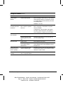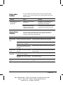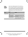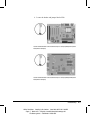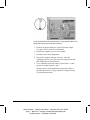
1
Troubleshooting Guide Compaq Deskpro Family of Personal Computers 122838-002 Cover.p65 1 6/21/1999, 11:43 AM Troubleshooting Guide Compaq Deskpro Family of Personal Computers Notice The information in this guide is subject to change without notice. COMPAQ COMPUTER CORPORATION SHALL NOT BE LIABLE FOR TECHNICAL OR EDITORIAL ERRORS OR OMISSIONS CONTAINED HEREIN; NOR FOR INCIDENTAL OR CONSEQUENTIAL DAMAGES RESULTING FROM THE FURNISHING, PERFORMANCE, OR USE OF THIS MATERIAL. This guide contains information protected by copyright. Except for use in connection with the accompanying Compaq product, no part of this guide may be photocopied or reproduced in any form without prior written consent from Compaq Computer Corporation. 1999 Compaq Computer Corporation. All rights reserved. Printed in the U.S.A. Compaq and Deskpro are registered in the U. S. Patent and Trademark Office. Microsoft, MS-DOS, Windows, Windows NT, and other names of Microsoft products referenced herein are trademarks or registered trademarks of Microsoft Corporation. Product names mentioned herein may be trademarks and/or registered trademarks of their respective companies. The software described in this guide is furnished under a license agreement or nondisclosure agreement. The software may be used or copied only in accordance with the terms of the agreement. The following words and symbols mark special messages throughout this guide: ! WARNING: Text set off in this manner indicates that failure to follow directions could result in bodily harm or loss of life. CAUTION: Text set off in this manner indicates that failure to follow directions could result in damage to equipment or loss of information. Troubleshooting Guide Compaq Deskpro Family of Personal Computers Second Edition (September 1999) First Edition (June 1999) Part Number 122838-002 Compaq Computer Corporation Writer: Debbie Thomson Saved By: Jake Schulzinger Saved Date: 05/26/99 10:45 AM Pages: 1 Words: 251 Template: c:\msoffice\templates\commnoti.dot File Name notice.doc Part Number 128838-002 C ONTENTS chapter 1 Troubleshooting Helpful Hints ............................................................................................................................1-2 Solving General Problems ........................................................................................................1-3 Solving Disk Problems .............................................................................................................1-5 Solving Graphics Problems ......................................................................................................1-7 Solving Audio Problems...........................................................................................................1-9 Solving Printer Problems..........................................................................................................1-9 Solving Hardware Installation Problems ................................................................................1-10 Solving Network Problems.....................................................................................................1-11 Solving Memory Problems.....................................................................................................1-14 Solving SCSI Problems ..........................................................................................................1-14 Solving CD-ROM and DVD Problems ..................................................................................1-15 Solving Software Problems ....................................................................................................1-15 Troubleshooting Using Compaq Intelligent Manageability Features.....................................1-16 Compaq Configuration Record Utility ...................................................................................1-16 Contacting Compaq Customer Support ..................................................................................1-17 chapter 2 POST Error Messages Error Codes...............................................................................................................................2-1 appendix A Password Security and Cleaing and Resetting CMOS ...................................................................A-1 appendix B Computer Diagnostics ....................................................................................................................... B-1 appendix C Drive Protection System (DPS) ......................................................................................................... C-1 Index ......................................................................................................................................................I-1 Troubleshooting iii Writer: Debbie Thomson Saved by: Jake Schulzinger Saved date: 06/21/99 8:15 AM Pages: 3 Words: 103 Template: c:\msoffice\templates\commtoc.dot File Name toc.doc Part Number 122838-001 122838-002 Writer: Debbie Thomson Saved by: Jake Schulzinger Saved date: 06/21/99 8:15 AM Pages: 3 Words: 103 Template: c:\msoffice\templates\commtoc.dot File Name toc.doc Part Number122838-002 chapter 1 T ROUBLESHOOTING This guide provides information on how to identify and correct minor disk, graphics, memory, and software problems. It also explains many of the messages that may be displayed on the screen, including specific error messages that may appear during the Power-On Self-Test (POST) at startup. POST Message Disabled suppresses most system messages during POST, such as memory count and non-error text messages. In this mode, the Compaq Logo and Web address appear on the computer monitor. If a POST error occurs, the screen will display the error message. To manually switch to the POST Messages Enabled mode during POST, press any key (except F10 or F12). The default mode is POST Message Disabled. The speed at which the computer loads the operating system and the extent to which it is tested are determined by the POST mode selection. Quick Boot is a fast startup process that does not run all of the system level tests, such as the memory test. Full Boot runs all of the ROM-based system tests and takes longer to complete. Full Boot may also be enabled to run every 1 to 30 days on a regularly scheduled basis. To establish the schedule, reconfigure your computer to the Full Boot Every xx Days mode, using Computer Setup. ✎ For more information on Computer Setup, refer to the Making Hardware Changes guide. Troubleshooting Writer: Elizabeth Hedstrom Saved By: Jake Schulzinger Saved Date: 06/21/99 8:14 AM Pages: 17 Words: 3780 Template: c:\msoffice\templates\comm.dot File Name ch1.doc Part Number 122838-002 1-1 Helpful Hints 1-2 If you encounter some minor problem with your computer, monitor, or software, refer to the following list of general suggestions before taking further action: ■ Check that the computer and monitor are plugged into a working electrical outlet. ■ Check to see that the computer is turned on and the green power light is on. ■ Check to see that the monitor is turned on and the green monitor light is on. ■ Turn up the brightness and contrast controls of the monitor if the monitor is dim. ■ Press and hold any key. If the system beeps, then your keyboard should be operating correctly. ■ Check all cable connections for loose connections or incorrect connections. ■ Reconfigure your computer after installing a non–Plug and Play expansion card or other option. See “Solving Hardware Installation Problems” for instructions. ■ Be sure that all the needed device drivers have been installed. For example, if you are using a printer, you need a printer driver. ■ Take out all diskettes from the diskette drives when you turn on your system. Troubleshooting Writer: Elizabeth Hedstrom Saved by: Jake Schulzinger Saved date: 06/21/99 8:14 AM Pages: 17 Words: 3780 Template: c:\msoffice\templates\comm.dot File Name ch1.doc Part Number 122838-002 Solving General Problems You may be able to easily resolve the minor problems described in this section. If a problem persists and you are unable to resolve it yourself, contact your Compaq authorized dealer or reseller. Problem Cause Solution Computer won't turn on Computer is not connected to an external power source. Connect to an external power source. Cables to the external power source are unplugged. Ensure that cables connecting the computer to the external power source are plugged in properly and the wall outlet is active. A defective PCI or ISA card has been installed. Remove any expansion card that was just installed. Drive power, data, or power supply cables may not be properly connected. Reseat drive power, data, and power supply cables. Computer appears locked up and won’t turn off when the power button is pressed Software control of the power switch is not functional. Press and hold the power button until the computer turns off. Computer date and time display is incorrect RTC (real-time clock) battery may need to be replaced. Battery life is approximately 5 years. First, reset the date and time under Control Panel. If the problem persists, replace the RTC battery. Refer to the Making Hardware Changes guide for instructions on installing a new battery, or contact your Compaq authorized dealer or reseller for RTC battery replacement. Computer powered off automatically (Red power LED blinks four times per second.) The unit temperature was exceeded. The fan may be blocked. 1. Unit is in an exceedingly hot environment. Let it cool down. 2. Ensure computer air vents are not blocked and internal fan is running. 3. Contact your Compaq authorized reseller or service provider. Computer appears to pause periodically The unit temperature was exceeded because the computer was functioning with the cover or access panel removed. Replace cover or access panel, and let the computer cool down before attempting to turn on power to the computer. Network driver is loaded and no network connection is established. Establish a network connection, or use Computer Setup or Windows Device Manager to disable the network controller. Continued Troubleshooting Writer: Elizabeth Hedstrom Saved By: Jake Schulzinger Saved Date: 06/21/99 8:14 AM Pages: 17 Words: 3780 Template: c:\msoffice\templates\comm.dot File Name ch1.doc Part Number 122838-002 1-3 Solving General Problems Continued Problem Cause Solution Cannot remove computer cover or access panel Smart Cover Lock, featured on some computers, is locked. Unlock the Smart Cover Lock using Computer Setup (F10 Setup). The Smart Cover FailSafe Key, a device for manually disabling the Smart Cover Lock, is available from Compaq. You’ll need the FailSafe Key in case of forgotten password, power loss, or computer malfunction. Cursor will not move using the arrow keys on the keypad 1-4 The Num Lock key may be on. Press the Num Lock key. The Num Lock light should not be on if you want to use the arrow keys. Troubleshooting Writer: Elizabeth Hedstrom Saved by: Jake Schulzinger Saved date: 06/21/99 8:14 AM Pages: 17 Words: 3780 Template: c:\msoffice\templates\comm.dot File Name ch1.doc Part Number 122838-002 Solving Disk Problems Common causes and solutions for disk problems are listed in the following table: ✎ You may need to reconfigure the computer when you add or remove hardware, such as an additional diskette drive. See “Solving Hardware Installation Problems” for instructions. Problem Cause Solution Diskette drive light stays on Diskette is damaged. In Windows 95 or 98, run ScanDisk. Click Start Æ Programs Æ Accessories Æ System Tools Æ ScanDisk. In Windows NT, right click Start, click Explore, and select a drive. Select File Æ Properties Æ Tools. Under Error-checking, click Check Now. Diskette is incorrectly inserted. Remove diskette and reinsert. Drive button is not pushed in. Push in drive button. Software program is damaged. Check the program diskettes. Drive cable is not properly connected. Reconnect drive cable. Diskette is not formatted. Format the diskette. Diskette is write-protected. Use another diskette or remove the write protection. Writing to the wrong drive. Check the drive letter in your path statement. Not enough space is left on the diskette. Use another diskette. Diskette write control is enabled. Use Computer Setup to check your storage security feature disabled settings. Diskette drive cannot write to a diskette Continued Troubleshooting Writer: Elizabeth Hedstrom Saved By: Jake Schulzinger Saved Date: 06/21/99 8:14 AM Pages: 17 Words: 3780 Template: c:\msoffice\templates\comm.dot File Name ch1.doc Part Number 122838-002 1-5 Solving Disk Problems Continued Problem Cause Solution Cannot format diskette Invalid media reported. When formatting a disk in DOS, you may need to specify diskette capacity. For example, to format a 1.44-MB diskette, type the following command at the DOS prompt: FORMAT A: /F:1440 A problem has occurred with a disk transaction The directory structure is bad, or there is a problem with a file. In Windows 95 or 98, run ScanDisk. Click Start Æ Programs Æ Accessories Æ System Tools Æ ScanDisk. In Windows NT, right click Start, click Explore, and select a drive. Select File Æ Properties Æ Tools. Under Error-checking, click Check Now. Diskette drive cannot read a diskette Diskette is not formatted. Format the diskette. You are using the wrong diskette type for the drive type. Check the type of drive you are using and use the correct diskette type. Cable is loose. Reseat diskette drive cable. Computer configuration does not recognize second diskette drive. Use Computer Setup (F10 Setup) to enable the second diskette drive. Select Diskettes from the Storage menu. Second Ultra ATA hard drive does not perform optimally You are using the wrong cable for the drive type. Reinstall the second Ultra ATA hard drive using an 80-conductor cable. The 80-conductor cable is standard on select models. Nonsystem disk message The system is trying to start from a nonsystem diskette. Remove the diskette from the drive. Drive not found 1-6 Troubleshooting Writer: Elizabeth Hedstrom Saved by: Jake Schulzinger Saved date: 06/21/99 8:14 AM Pages: 17 Words: 3780 Template: c:\msoffice\templates\comm.dot File Name ch1.doc Part Number 122838-002 Solving Graphics Problems If you encounter graphics problems, refer to the documentation that came with your monitor and to the common causes and solutions listed in the following table: Problem Cause Solution Blank screen Monitor is not turned on and the monitor light is not on. Turn on the monitor and check that the monitor light is on. The cable connections are not correct. Check the cable connection from the monitor to the computer and to the electrical outlet. The energy saver feature has been enabled. Press any key or click the mouse button and, if set, type your password. The RGB (Red, Green, Blue) input switch on the monitor is incorrectly set. Set the monitor’s RGB input switch to 75 ohms and, if there is a sync switch, set it to External. System ROM is bad; system is running in Failsafe Boot Block mode (indicated by one long beep and three short beeps). Reflash the ROM using a ROMPaq diskette. Refer to the “Failsafe Boot Block ROM” section of the Desktop Management guide for more information. You are using a fixed-sync monitor and it won't sync at the resolution chosen. Be sure that the monitor can accept the same sweep rate as the resolution chosen. The VGA/BNC selector switch is not properly set. Set the selector switch to agree with the cable connection. Monitor without energy saver capabilities is being used with energy saver features enabled. Disable monitor energy saver feature. Monitor does not function properly when used with energy saver features Continued Troubleshooting Writer: Elizabeth Hedstrom Saved By: Jake Schulzinger Saved Date: 06/21/99 8:14 AM Pages: 17 Words: 3780 Template: c:\msoffice\templates\comm.dot File Name ch1.doc Part Number 122838-002 1-7 Solving Graphics Problems Continued Problem Cause Solution Graphics colors are wrong The cabling or monitor impedance is incorrect. 1. If you are using BNC cables, be sure that the Red, Green, and Blue BNC cables are connected to the corresponding monitor connectors. 2. Be sure your monitor’s RGB inputs are set to 75 ohms. Dim characters The brightness and contrast controls are not set properly. Adjust the monitor brightness and contrast controls. Cables are not properly connected. Check that the graphics cable is securely connected to the graphics card and the monitor. The RGB switch on the back of the monitor is incorrectly set. Set the RGB switch (and sync options, if this option is available) to 75 ohms, with the sync set to external. Refer to the documentation included with the monitor. Blurry video or requested resolution cannot be set If the graphics controller was upgraded, the correct graphics drivers may not be loaded. Install the video drivers on the diskette included in the upgrade kit. Screen goes blank You may have a screen blanking utility installed or energy saver features are enabled. Press any key or type password. The picture is broken up, or it rolls, jitters, or blinks The monitor connections may be incomplete or the monitor may be incorrectly adjusted. 1. Be sure the monitor cable is securely connected to the computer. 2. In a 2-monitor system or if another monitor is in close proximity, be sure the monitors are not interfering with each other’s electromagnetic field by moving them apart. 3. Fluorescent lights or fans may be too close to the monitor. Monitor overheats 1-8 There is not enough ventilation space for proper airflow. Leave at least 3 inches (7.6 cm) of ventilation space. Be sure there is nothing sitting on top of the monitor obstructing the air flow. Troubleshooting Writer: Elizabeth Hedstrom Saved by: Jake Schulzinger Saved date: 06/21/99 8:14 AM Pages: 17 Words: 3780 Template: c:\msoffice\templates\comm.dot File Name ch1.doc Part Number 122838-002 Solving Audio Problems If your computer has audio features and you encounter audio problems, refer to the common causes and solutions listed in the following table: Problem Cause Solution Sound does not come out of the speaker or headphones Software volume control is turned down. Double click on the speaker icon on the taskbar, then set volume by adjusting the volume slider. CD-ROM or DVD volume control on the front of the computer is turned down. Turn the volume control knob on front of computer to increase the volume. Solving Printer Problems If you encounter printer problems, refer to the documentation that came with your printer and to the common causes and solutions listed in the following table: Problem Cause Solution Printer will not print Printer is not turned on and online. Turn the printer on and make sure it is online. The correct printer drivers for your application are not installed. Install the correct printer drivers for your application. If you are on a network, you may not have made the connection to the printer. Make the proper network connections to the printer. Printer will not turn on The cables may not be connected properly. Reconnect all cables and check the power cord and electrical outlet. Prints garbled information The correct printer driver for your application is not installed. Install the correct printer driver for your application. The cables may not be connected properly. Reconnect all cables. The printer may be out of paper. Check the paper tray and refill it if it is empty. Select online. Printer is offline Troubleshooting Writer: Elizabeth Hedstrom Saved By: Jake Schulzinger Saved Date: 06/21/99 8:14 AM Pages: 17 Words: 3780 Template: c:\msoffice\templates\comm.dot File Name ch1.doc Part Number 122838-002 1-9 Solving Hardware Installation Problems You may need to reconfigure the computer when you add or remove hardware, such as an additional diskette drive. If you install a Plug and Play device, Windows 95 and Windows 98 automatically recognize the device and configure the computer. If you install a non–Plug and Play device, you must reconfigure the computer after completing installation of the new hardware. In Windows 95 and Windows 98, select the Add New Hardware icon in the Control Panel and follow the instructions that appear on the screen. To reconfigure the computer in Windows NT 4.0 after installing new hardware, use the utility provided with the hardware. Problem Cause Solution A new device is not recognized as part of the computer system The computer needs to be reconfigured to recognize the device. Follow the reconfiguration instructions above. Cable(s) of new external device are loose or power cables are unplugged. Ensure that all cables are properly and securely connected and that pins in the cable or connector are not bent down. Power switch of new external device is not turned on. Turn off the computer, turn on the external device, then turn on the computer to integrate the device with the computer system. 1-10 Troubleshooting Writer: Elizabeth Hedstrom Saved by: Jake Schulzinger Saved date: 06/21/99 8:14 AM Pages: 17 Words: 3780 Template: c:\msoffice\templates\comm.dot File Name ch1.doc Part Number 122838-002 Solving Network Problems Some common causes and solutions for network problems are listed in the following table. These guidelines do not discuss the process of debugging the network cabling. Problem Cause Solution Remote Wakeup feature is not functioning The Remote Wakeup feature is not available when using an AUI network connection. Use an RJ-45 network connection. Remote Wakeup is not enabled. Use the Network control application to enable Remote Wakeup. Refer to the Desktop Management guide. Network driver does not detect network controller Network controller is disabled. Run Computer Setup and enable network controller. Network status link light does not turn on or flashes No active network is detected. Check cabling and network equipment for proper connection. Network controller is not set up properly. Use the Network control application to verify that device is working properly. Refer to the Using Network Communications guide. System is configured for AUI connection. No solution; link LED does not apply to AUI connections. Network driver is not properly loaded. Reinstall network drivers. Refer to the Using Network Communications guide. System cannot autosense the network. Disable autosensing capabilities and force the system into the correct operating mode. Refer to the Using Network Communications guide. Continued Troubleshooting Writer: Elizabeth Hedstrom Saved By: Jake Schulzinger Saved Date: 06/21/99 8:14 AM Pages: 17 Words: 3780 Template: c:\msoffice\templates\comm.dot File Name ch1.doc Part Number 122838-002 1-11 Solving Network Problems continued Problem Cause Solution Diagnostics reports a failure The cable is not securely connected. Ensure that the cable is securely attached to the network connector and that the other end of the cable is securely attached to the correct device. The cable is attached to the incorrect connector. Ensure that the cable is attached to the correct connector. There is a problem with the cable or a device at the other end of the cable. Ensure that the cable and device at the other end are operating correctly. The network controller is defective. Contact your Compaq authorized service provider. Network controller interrupt is shared with an expansion card. Under the Computer Setup Advanced menu, change the resource settings for the card. Network drivers are not loaded, or driver parameters do not match current configuration. Make sure the network drivers are loaded and that the driver parameters match the configuration of the network controller. The network controller is not configured for this computer. Select the Network icon at the Control Panel and configure the network controller. Diagnostics passes, but the computer does not communicate with the network Continued 1-12 Troubleshooting Writer: Elizabeth Hedstrom Saved by: Jake Schulzinger Saved date: 06/21/99 8:14 AM Pages: 17 Words: 3780 Template: c:\msoffice\templates\comm.dot File Name ch1.doc Part Number 122838-002 Solving Network Problems continued Problem Cause Solution Network controller stopped working when an expansion board was added to the computer Network controller interrupt is shared with an expansion board. Under the Computer Setup Advanced menu, change the resource settings for the board. The network controller requires drivers. Verify that the drivers were not accidentally deleted when the drivers for a new expansion board were installed. The files containing the network drivers are corrupted. Reinstall the network drivers, using the Compaq Restore CD. The files containing the network drivers are corrupted. Reinstall the network drivers, using the Compaq Restore CD. The cable is not securely connected. Ensure that the cable is securely attached to the network connector and that the other end of the cable is securely attached to the correct device. The network controller is defective. Contact your Compaq authorized service provider. New network card will not boot New network card may not be Compaq compatible. Install Compaq-compatible NIC or change boot sequence to boot from another device. Cannot connect to network server when attempting Remote System Installation The network controller is not configured properly. Run Computer Setup (F10 Setup) and modify the NIC Settings. Network controller stopped working without apparent cause Troubleshooting Writer: Elizabeth Hedstrom Saved By: Jake Schulzinger Saved Date: 06/21/99 8:14 AM Pages: 17 Words: 3780 Template: c:\msoffice\templates\comm.dot File Name ch1.doc Part Number 122838-002 1-13 Solving Memory Problems If you encounter memory problems, some common causes and solutions are listed in the following table: Problem Cause Solution System won't boot or does not function properly after installing additional memory modules Memory module is not the correct type or speed grade for the system or the new memory module is not seated properly. Replace module with the correct industrystandard device for your computer. Out of Memory error Memory configuration may not be set up correctly. Use the Device Manager to check memory configuration. You have run out of memory to run the application. Check the application documentation to determine the memory requirements. Memory count during POST is wrong The memory modules may not be installed correctly. Check that the memory modules have been installed correctly and that proper modules are used. Insufficient memory error during operation Too many Terminate and Stay Resident programs (TSRs) are installed. Delete any TSRs that you do not need. You have run out of memory for your application. Check the memory requirements for the application or add more memory to the computer. Solving SCSI Problems If you encounter SCSI device problems, refer to the common causes and solutions listed in the following table: Problem Cause Solution System with IDE and SCSI drives will not boot from SCSI hard drive The IDE drive is not disabled through the Computer Setup utility. Under the Computer Setup Advanced menu, disable the primary IDE controller. System without an IDE drive will not boot from a SCSI drive The SCSI drive is not configured correctly. Ensure that drive cabling and jumpers are set correctly. To boot a SCSI drive, the drive ID number must be set to 0. 1-14 Troubleshooting Writer: Elizabeth Hedstrom Saved by: Jake Schulzinger Saved date: 06/21/99 8:14 AM Pages: 17 Words: 3780 Template: c:\msoffice\templates\comm.dot File Name ch1.doc Part Number 122838-002 Solving CD-ROM and DVD Problems If you encounter CD-ROM or DVD problems, refer to the common causes and solutions listed in the following table or to the documentation that came with the optional device. Problem Cause Solution System will not boot from CD-ROM or DVD drive The CD-ROM or DVD boot is not enabled through the Computer Setup utility. Run the Computer Setup utility (F10 Setup) and set the drive priorities. Non-bootable CD in drive. Try a bootable CD in the drive. CD-ROM or DVD devices are not detected or driver is not loaded Drive is not connected properly or not properly configured. Refer to the documentation that came with the optional device. Movie will not play in the DVD drive Movie may be regionalized for a different country. Refer to the documentation that came with the DVD drive. Solving Software Problems Most software problems occur as a result of the following: ■ The application was not installed or configured correctly. ■ There is insufficient memory available to run the application. ■ There is a conflict between applications. Where available, run the Compaq Configuration Utility to determine if any changes have been made to the software which may be causing a problem. Refer to the online Intelligent Manageability guide for more information. Troubleshooting Writer: Elizabeth Hedstrom Saved By: Jake Schulzinger Saved Date: 06/21/99 8:14 AM Pages: 17 Words: 3780 Template: c:\msoffice\templates\comm.dot File Name ch1.doc Part Number 122838-002 1-15 Troubleshooting Using Compaq Intelligent Manageability Features The Local Alert Pop-Up Dialog notifies you of an impending or actual hardware failure. If the computer is connected to a network and the Compaq Insight Management Agents are installed and configured, a Simple Network Management Protocol (SNMP) trap (message) is sent to the specified SNMPcompliant management application. The Local Alert Pop-Up Dialog also tells you the steps you need to take prior to a hardware failure to avoid loss of data and damage to the computer. The system administrator can create a customized action message that might include contact telephone or pager numbers. To close the Local Alert Pop-Up Dialog, click the Close button. To retrieve fault information after closing the dialog, run Computer Diagnostics. For more detailed information, refer to the online Intelligent Manageability guide and the Desktop Management guide. Compaq Configuration Record Utility Compaq Configuration Record Utility is an online informationgathering tool similar to other Compaq management tools. It gathers critical hardware and software information from various sources to give a complete view of the computer. Configuration Record Utility provides a means for automatically identifying and comparing configuration changes, and has the ability to maintain a computer configuration history. The information can be saved as a history of multiple sessions. This utility was developed to allow resolution of problems without taking the computer off-line and to assist in maximizing computer availability. The information obtained by the utility is useful in troubleshooting computer problems, and streamlines the service process by enabling quick and easy identification of computer configurations, which is the first step in resolving service cases. The Compaq Configuration Record Utility is accessed via an icon in the Control Panel. When running the utility, information is automatically gathered on such items as the operating system version number, operating system parameters, and the operating system startup files. The utility then combines this information with information on the hardware configuration to deliver a comprehensive view of the computer. 1-16 Troubleshooting Writer: Elizabeth Hedstrom Saved by: Jake Schulzinger Saved date: 06/21/99 8:14 AM Pages: 17 Words: 3780 Template: c:\msoffice\templates\comm.dot File Name ch1.doc Part Number 122838-002 Contacting Compaq Customer Support For help and service, contact your Compaq authorized reseller or dealer. For a list of phone numbers, consult the warranty. ✎ If you take your computer to a Compaq authorized reseller, dealer, or service provider for service, remember to provide the setup and power-on passwords, if they are set. Troubleshooting Writer: Elizabeth Hedstrom Saved By: Jake Schulzinger Saved Date: 06/21/99 8:14 AM Pages: 17 Words: 3780 Template: c:\msoffice\templates\comm.dot File Name ch1.doc Part Number 122838-002 1-17 chapter 2 POST E RROR M ESSAGES Error Codes This chapter lists the error codes that you may encounter during the Power-On Self-Test (POST) or computer restart, the probable source of the problem, and what steps you can take to resolve the error condition. Power-On Self-Test Messages Message Beeps* Probable Cause 101-Option ROM Error 1L, 1S System ROM checksum. Recommended Action 1. Verify the correct ROM 2. Flash the ROM if needed. 3. If an expansion card was recently added, remove it and see if the problem remains. 4. If the message disappears, there may be a problem with the expansion card. 5. Replace the system board. 102-System Board Failure None DMA, timers, etc. 1. Clear CMOS. 2. Remove expansion boards. 3. Replace the system board. 103-System Board Failure None DMA, timers, etc. 1. Clear CMOS. 2. Remove expansion boards. 3. Replace the system board. Continued * L = Long, S = Short Troubleshooting Writer: Elizabeth Hedstrom Saved By: Jake Schulzinger Saved Date: 06/14/99 11:24 AM Pages: 13 Words: 2422 Template: c:\msoffice\templates\comm.dot File Name ch2.doc Part Number 122838-002 2-1 Power-On Self-Test Messages Continued Message Beeps* Probable Cause Recommended Action 162-System Options Not Set 2S Configuration incorrect. Run Computer Setup (F10 Setup). RTC (real-time clock) battery may need to be replaced. Battery life is approximately 5 years. Reset the date and time under Control Panel. If the problem persists, replace the RTC battery. Refer to the Making Hardware Changes guide for instructions on installing a new battery, or contact your Compaq authorized dealer or reseller for RTC battery replacement. 163-Time & Date Not Set 2S Invalid time or date in configuration memory. RTC (real-time clock) battery may need to be replaced. Battery life is approximately 5 years. Reset the date and time under Control Panel. If the problem persists, replace the RTC battery. Refer to the Making Hardware Changes guide for instructions on installing a new battery, or contact your Compaq authorized dealer or reseller for RTC battery replacement. CMOS jumper may not be properly installed Check for proper placement of the CMOS jumper (if applicable). 164-Memory Size Error 2S Memory configuration incorrect. 1. Run Computer Setup (F10 Setup) or Windows utilities. 2. Make sure your memory module(s) are installed properly. 3. Verify proper memory module type. 183-Invalid Processor Jumper Setting 2S System board jumper improperly set. Reset system board jumpers to match processor and bus speeds (select models). * L = Long, S = Short 2-2 POST Error Messages Writer: Elizabeth Hedstrom Saved by: Jake Schulzinger Saved date: 06/14/99 11:24 AM Pages: 13 Words: 2422 Template: c:\msoffice\templates\comm.dot File Name ch2.doc Part Number 122838-002 Continued Power-On Self-Test Messages Continued Message Beeps* Probable Cause 201-Memory Error None RAM failure. Recommended Action 1. Run Computer Setup (F10 Setup) or Windows utilities. 2. Ensure memory and continuity modules are installed correctly. 3. Verify proper memory module type. 4. Remove and replace the memory module(s) one at a time to isolate faulty module. 5. Replace faulty memory module(s). 6. If error persists after replacing memory modules, replace the system board. 202-Memory Type Mismatch None Memory modules do not match each other. 207-ECC Corrected Single Bit Errors in DIMM/SIMM Pair(s) x,x in Memory Module Socket(s) y,y,… 2S Single Bit ECC error. 213-Incompatible DIMM Module in DIMM Socket(s) X, X, … 2S 301-Keyboard Error None Replace memory modules with matched sets. 1. Verify proper memory module type. 2. Try another memory socket. 3. Replace memory module if problem persists. A DIMM module in DIMM socket identified in the error message is missing critical SPD information, or is incompatible with the chipset. Keyboard failure. 1. Verify proper memory module type. 2. Try another memory socket. 3. Replace DIMM with a module conforming to the SPD standard. 1. Reconnect keyboard with computer turned off. 2. Check connector for bent or missing pins. 3. Ensure that none of the keys are depressed. 4. Replace keyboard. Continued * L = Long, S = Short Troubleshooting Writer: Elizabeth Hedstrom Saved By: Jake Schulzinger Saved Date: 06/14/99 11:24 AM Pages: 13 Words: 2422 Template: c:\msoffice\templates\comm.dot File Name ch2.doc Part Number 122838-002 2-3 Power-On Self-Test Messages Continued Message Beeps* Probable Cause 304-Keyboard or System Unit Error None Keyboard failure. Recommended Action 1. Reconnect the keyboard with computer turned off. 2. Ensure that none of the keys are depressed. 3. Replace the keyboard. 4. Replace the system board. 401-Parallel Port 1 Address Assignment Conflict 2S IRQ address conflicts with another device. Reset the IRQ. 403-Parallel Port 3 Address Conflict Detected 2S IRQ address conflicts with another device. Reset the IRQ. 404-Parallel Port Address Conflict Detected 2S Both external and internal ports are assigned to parallel port X. 1. Remove any parallel port expansion cards. 2. Clear CMOS. 3. Reconfigure card resources and/or run Computer Setup (F10 Setup). 410-Audio Interrupt Conflict 2S IRQ address conflicts with another device. Reset the IRQ. 411-Network Interface Card Interrupt Conflict 2S IRQ address conflicts with another device. Reset the IRQ. 501-Display Adapter Failure 1L, 2S Graphics display controller. 1. Reseat the graphics card (if applicable). 2. Clear CMOS. 3. Verify monitor is attached and turned on. 4. Replace the graphics controller. * L = Long, S = Short 2-4 POST Error Messages Writer: Elizabeth Hedstrom Saved by: Jake Schulzinger Saved date: 06/14/99 11:24 AM Pages: 13 Words: 2422 Template: c:\msoffice\templates\comm.dot File Name ch2.doc Part Number 122838-002 Continued Power-On Self-Test Messages Continued Message Beeps* Probable Cause 601-Diskette Controller Error None Diskette controller circuitry or floppy drive circuitry incorrect. Recommended Action 1. Run Computer Setup (F10 Setup). 2. Check and/or replace cables. 3. Clear CMOS. 4. Replace diskette drive. 5. Replace the system board. 602-Diskette Boot Record Error None Diskette in Drive A not bootable. 605-Diskette Drive Type Error 2S Mismatch in drive type. Replace the diskette. 1. Run Computer Setup (F10 Setup) or Windows NT, Windows 95, or Windows 98 utilities. 2. Disconnect any other diskette controller devices (tape drives). 3. Clear CMOS. 610-External Storage Device Failure None External tape drive not connected. 611-Primary Floppy Port Address Assignment Conflict 2S Configuration error. 612-Secondary Floppy Port Address Assignment Conflict 2S 660-Display cache is detected unreliable None 912- Computer Cover Has Been Removed Since Last System Startup None Reinstall tape drive or press F1 and allow system to reconfigure without the drive. 1. Run Computer Setup (F10 Setup). 2. Remove expansion cards. 3. Clear CMOS. Configuration error. 1. Run Computer Setup (F10 Setup). 2. Remove expansion cards. 3. Clear CMOS. Integrated graphics controller display cache not working properly and will be disabled. Replace system board if minimal graphics degrading is an issue. No action required. Continued * L = Long, S = Short Troubleshooting Writer: Elizabeth Hedstrom Saved By: Jake Schulzinger Saved Date: 06/14/99 11:24 AM Pages: 13 Words: 2422 Template: c:\msoffice\templates\comm.dot File Name ch2.doc Part Number 122838-002 2-5 Power-On Self-Test Messages Continued Message Beeps* Probable Cause 914-Hood Lock Coil is not Connected None Smart Cover Lock mechanism is missing or not connected. Recommended Action 1. Reconnect or replace Smart Cover Lock. 2. Reseat or replace Smart Cover Lock cable. 916-Thermal Sensor from Processor Heatsink is not Connected None Processor heatsink cable not connected to system board. Reseat or replace the processor heatsink cable going to the system board. 917-Expansion Riser not Detected None Riser board not seated or not installed. Install riser board if missing or remove and reseat to ensure good connection. 1151-Serial Port 1 Address Conflict Detected 2S Both external and internal serial ports are assigned to COM1. 1. Remove any serial port expansion cards. 2. Clear CMOS. 3. Reconfigure card resources and/or run Computer Setup (F10 Setup). 1152- Serial Port 2 Address Conflict Detected 2S Both external and internal serial ports are assigned to COM2. 1. Remove any serial port expansion cards. 2. Clear CMOS. 3. Reconfigure card resources and/or run Computer Setup (F10 Setup). 1155-Serial Port Address Conflict Detected 2S Both external and internal serial ports are assigned to same IRQ. 1. Remove any serial port expansion cards. 2. Clear CMOS. 3. Reconfigure card resources and/or run Computer Setup (F10 Setup). 1201-System Audio Address Conflict Detected 2S Device IRQ address conflicts with another device. Reset the IRQ. * L = Long, S = Short 2-6 POST Error Messages Writer: Elizabeth Hedstrom Saved by: Jake Schulzinger Saved date: 06/14/99 11:24 AM Pages: 13 Words: 2422 Template: c:\msoffice\templates\comm.dot File Name ch2.doc Part Number 122838-002 Continued Power-On Self-Test Messages Continued Message Beeps* Probable Cause Recommended Action 1202-MIDI Port Address Conflict Detected 2S Device IRQ address conflicts with another device. Reset the IRQ. 1203-Game Port Address Conflict Detected 2S Device IRQ address conflicts with another device. Reset the IRQ. 1720-SMART Hard Drive Detects Imminent Failure None Hard drive is about to fail. (Some hard drives have a firmware patch that will fix an erroneous error message). 1. Determine if hard drive is giving correct error message. Run the Drive Protection System test if available. 2. Apply firmware patch if applicable. 3. Back up contents and replace hard drive. 1721-SMART SCSI Hard Drive Detects Imminent Failure 1771-Primary Disk Port Address Assignment Conflict None 2S Hard drive is about to fail. (Some hard drives have a firmware patch that will fix an erroneous error message). Internal and external hard drive controllers are both assigned to the primary address. 1. Determine if hard drive is giving correct error message. 2. Apply firmware patch if applicable. 3. Back up contents and replace hard drive. 1. Remove any serial port expansion cards. 2. Clear CMOS. 3. Reconfigure card resources and/or run Computer Setup (F10 Setup). Continued * L = Long, S = Short Troubleshooting Writer: Elizabeth Hedstrom Saved By: Jake Schulzinger Saved Date: 06/14/99 11:24 AM Pages: 13 Words: 2422 Template: c:\msoffice\templates\comm.dot File Name ch2.doc Part Number 122838-002 2-7 Power-On Self-Test Messages Continued Message Beeps* Probable Cause 1772-Secondary Disk Port Address Assignment Conflict 2S Internal and external hard drive controllers are both assigned to the secondary address. 1780-Disk 0 Failure None Hard drive/format error. Recommended Action 1. Remove any serial port expansion cards. 2. Clear CMOS. 3. Reconfigure card resources and/or run Computer Setup (F10 Setup). 1. Run Computer Setup (F10 Setup). 2. Clear CMOS. 3. Check cables/jumper settings. 4. Run hard drive diagnostics. 5. Disconnect additional drives. 6. Run the Drive Protection System test if available. 7. Replace the hard drive. 1781-Disk 1 Failure None Hard drive/format error. 1. Run Computer Setup (F10 Setup). 2. Clear CMOS. 3. Check cables/jumper settings. 4. Run hard drive diagnostics. 5. Disconnect additional drives. 6. Run the Drive Protection System test if available. 7. Replace the hard drive. * L = Long, S = Short 2-8 POST Error Messages Writer: Elizabeth Hedstrom Saved by: Jake Schulzinger Saved date: 06/14/99 11:24 AM Pages: 13 Words: 2422 Template: c:\msoffice\templates\comm.dot File Name ch2.doc Part Number 122838-002 Continued Power-On Self-Test Messages Continued Message Beeps* Probable Cause 1782-Disk Controller Failure None Hard drive circuitry error. Recommended Action 1. Run Computer Setup (F10 Setup). 2. Clear CMOS. 3. Check cable seating/jumper settings. 4. Run hard drive diagnostics. 5. Disconnect additional drives. 6. Run the Drive Protection System test if available. 7. Replace the hard drive. 8. Replace the system board. 1790-Disk 0 Error None Hard drive error or wrong drive type. 1. Run Computer Setup (F10 Setup). 2. Clear CMOS. 3. Check cable seating jumper settings. 4. Run hard drive diagnostics. 5. Disconnect additional drives. 6. Confirm drive is supported on this computer (large drive ROM support). 7. Run the Drive Protection System test if available. 8. Replace the hard drive. 9. Replace the system board. Continued * L = Long, S = Short Troubleshooting Writer: Elizabeth Hedstrom Saved By: Jake Schulzinger Saved Date: 06/14/99 11:24 AM Pages: 13 Words: 2422 Template: c:\msoffice\templates\comm.dot File Name ch2.doc Part Number 122838-002 2-9 Power-On Self-Test Messages Continued Message Beeps* Probable Cause 1791-Disk 1 Error None Hard drive error or wrong drive type. Recommended Action 1. Run Computer Setup (F10 Setup). 2. Clear CMOS. 3. Check cable seating/jumper settings. 4. Run hard drive diagnostics. 5. Disconnect additional drives. 6. Confirm drive is supported on this computer (large drive ROM support). 7. Run the Drive Protection System test if available. 8. Replace the hard drive. 9. Replace the system board. 1792-Secondary Disk Controller Failure None Hard drive circuitry error. 1. Run Computer Setup (F10 Setup). 2. Clear CMOS. 3. Check cable seating/jumper settings. 4. Run hard drive diagnostics. 5. Disconnect additional drives. 6. Run the Drive Protection System test if available. 7. Replace the hard drive. 1793-Secondary Controller or Disk Failure None Hard drive circuitry error. 1. Run Computer Setup (F10 Setup). 2. Clear CMOS. 3. Check cable seating/jumper settings. 4. Run hard drive diagnostics. 5. Disconnect additional drives. 6. Run the Drive Protection System test if available. 7. Replace the hard drive. * L = Long, S = Short 2-10 POST Error Messages Writer: Elizabeth Hedstrom Saved by: Jake Schulzinger Saved date: 06/14/99 11:24 AM Pages: 13 Words: 2422 Template: c:\msoffice\templates\comm.dot File Name ch2.doc Part Number 122838-002 Continued Power-On Self-Test Messages Continued Message Beeps* Probable Cause 1800-Temperature Alert None Internal temperature exceeds specification. Recommended Action 1. Check that computer air vents are not blocked and cooling fan is running. 2. Verify processor speed selection. 3. Replace the processor. 4. Replace the system board. 1801 None Processor not supported by ROM Bios. Upgrade BIOS to proper version. Audible 1L, 3S System ROM is bad; system is running in Failsafe Boot Block mode. Reflash the ROM using a ROMPaq diskette. Refer to the “Failsafe Boot Block ROM” section of the Intelligent Manageability guide. Audible 2S Power-on successful. None. Flashing Caps Lock LED on Keyboard 1L, 2S Graphics controller not present or incorrectly initialized. 1. Following directions in Appendix A to clear CMOS. System memory not present. 1. Check memory module (refer to the relevant section of the Making Hardware Changes guide). Flashing Num Lock LED on Keyboard 1S, 2L 2. If graphics card has been added, remove and reseat. 2. Remove and reseat memory module. 3. See the “Solving Memory Problems” section of this guide. Num Lock LED ON (keyboard) None Failed Boot Block. Reflash the ROM using a ROMPaq diskette. Refer to the “Failsafe Boot Block ROM” section of the Intelligent Manageability guide. Flashing Scroll Lock LED on keyboard 2L, 1S System board hardware failure (prior to graphics). Replace system board. Continued * L = Long, S = Short Troubleshooting Writer: Elizabeth Hedstrom Saved By: Jake Schulzinger Saved Date: 06/14/99 11:24 AM Pages: 13 Words: 2422 Template: c:\msoffice\templates\comm.dot File Name ch2.doc Part Number 122838-002 2-11 Power-On Self-Test Messages Continued Message Beeps* Probable Cause Recommended Action Green Power LED Blinks 1x / Second. None Computer in normal Suspend mode. None Green Power LED On None Computer on. None Invalid Electronic Serial Number None Electronic serial number has become corrupted. Run Computer Setup. If Setup already has data in the field or will not allow the serial number to be entered, download from www.compaq.com and run SP5572.EXE (SNZERO.EXE). Flashing Power and Hard Drive Green LEDs None Unseated riser board. Red Power LED Blinks Every 2 or more Seconds. None 1. Remove riser board. 2. Wipe connector. 3. Reinstall (refer to the Making Hardware Changes guide for directions on removing the riser board). Power supply overloaded. 1. Push in power button. LED should be green. 2. Remove all AC power from computer, wait 30 seconds, then apply power. 3. Remove load from power supply by removing options one at a time until computer runs. 4. Check for damage to system board. 5. Replace system board. 6. Replace power supply. Red Power LED Blinks Every Second None System memory error. 1. Check memory module (refer to the relevant section of the Making Hardware Changes guide). 2. Remove and reseat memory module. 3. See the “Solving Memory Problems” section of this guide. * L = Long, S = Short 2-12 POST Error Messages Writer: Elizabeth Hedstrom Saved by: Jake Schulzinger Saved date: 06/14/99 11:24 AM Pages: 13 Words: 2422 Template: c:\msoffice\templates\comm.dot File Name ch2.doc Part Number 122838-002 Continued Power-On Self-Test Messages Continued Message Beeps* Probable Cause Red Power LED Blinks Four Times per Second None Computer overheated. Red Power LED On None Recommended Action 1. Install computer cover or access panel if necessary. 2. Ensure that computer air vents are not blocked and internal fan is running. Processor unseated. Reseat processor in system board. * L = Long, S = Short ✎ If you have replaced the standard keyboard with a Universal Serial Bus (USB) keyboard, you will hear the beep sequences for these error codes but will not see the flashing keyboard lights. Troubleshooting Writer: Elizabeth Hedstrom Saved By: Jake Schulzinger Saved Date: 06/14/99 11:24 AM Pages: 13 Words: 2422 Template: c:\msoffice\templates\comm.dot File Name ch2.doc Part Number 122838-002 2-13 appendix A P ASSWORD S ECURITY AND C LEARING AND R ESETTING CMOS This computer supports security password features, which can be established through the Computer Setup Utilities menu. This computer supports two security password features that are established through the Computer Setup (F10 Setup) Utilities menu: setup password and power-on password. When you establish only a setup password, any user can access all the information on the computer except Computer Setup (F10 Setup). When you establish only a power-on password, the power-on password is required to access Computer Setup (F10 Setup) and any other information on the computer. When you establish both passwords, only the setup password will give you access to Computer Setup (F10 Setup). When both passwords are set, the setup password can also be used in place of the power-on password as an override to log into the computer. This is a useful feature for a network administrator. If you forget the password for your computer, there are two methods for clearing that password so you may gain access to the information on the computer: ■ Resetting the password jumper ■ Using the Clear CMOS button CAUTION: Pushing the CMOS button will reset CMOS values to factory defaults and will erase any customized information including passwords, asset numbers, and special settings. Troubleshooting Writer: Your Name Saved by: Lydia Sanchez Saved date: 06/21/99 11:00 AM Pages: 7 Words: 959 Template: c:\msoffice\templates\commapp.dot File Name appa.doc Part Number 122838-002 A-1 Resetting the Password Jumper To disable the power-on or setup password features, or to clear the power-on or setup passwords, complete the following steps: 1. Turn off the computer and any external devices, and disconnect the power cord from the power outlet. 2. Disconnect the keyboard, monitor, and any other external devices connected to the computer. ! WARNING: To reduce the risk of personal injury from electrical shock and/or hot surfaces, be sure to disconnect the power cord from the wall outlet, and allow the internal system components to cool before touching. CAUTION: When the computer is plugged in, the power supply always has voltage applied to the system board even when the unit is turned off. Failure to disconnect the power cord can result in damage to the system. CAUTION: Static electricity can damage the electronic components of the computer or optional equipment. Before beginning these procedures, ensure that you are discharged of static electricity by briefly touching a grounded metal object. Refer to the Safety & Regulatory Information guide for more information. 3. Remove the computer cover or access panel. A-2 Password Security and Cleaning and Resetting CMOS Writer: Your Name Saved by: Lydia Sanchez Saved date: 06/21/99 11:00 AM Pages: 7 Words: 959 Template: c:\msoffice\templates\commapp.dot File Name appa.doc Part Number 122838-002 4. Locate the header and jumper labeled E49. Location and Identification of the Password Jumper on a Compaq Deskpro EP System Board (Intel 810 Chipset) Location and Identification of the Password Jumper on a Compaq Deskpro EN System Board (Intel 810 Chipset) Troubleshooting Writer: Your Name Saved by: Lydia Sanchez Saved date: 06/21/99 11:00 AM Pages: 7 Words: 959 Template: c:\msoffice\templates\commapp.dot File Name appa.doc Part Number 122838-002 A-3 Location and Identification of the Password Jumper on a Compaq Deskpro EN SFF, FrontMounted Audio Solution System Board (Intel 810 Chipset) 5. Remove the jumper from pins 1 and 2. Place the jumper over pin 2 only, in order to avoid losing it. 6. Replace the computer cover or access panel. 7. Reconnect the external equipment. 8. Plug in the computer and turn on power. Allow the operating system to start. This clears the current passwords and disables the password features. 9. To re-enable the password features, repeat steps 1-4, then replace the jumper on pins 1 and 2. Repeat steps 6-8, then establish new passwords. Refer to the Making Hardware Changes guide for Computer Setup (F10 Setup) instructions. A-4 Password Security and Cleaning and Resetting CMOS Writer: Your Name Saved by: Lydia Sanchez Saved date: 06/21/99 11:00 AM Pages: 7 Words: 959 Template: c:\msoffice\templates\commapp.dot File Name appa.doc Part Number 122838-002 Clearing and Resetting the CMOS The computer’s configuration memory (CMOS) stores password information as well information about the computer’s configuration. Using the CMOS Button 1. Turn off the computer and any external devices, and disconnect the power cord from the power outlet. 2. Disconnect the keyboard, monitor, and any other external equipment connected to the computer. ! WARNING: To reduce the risk of personal injury from electrical shock and/or hot surfaces, be sure to disconnect the power cord from the wall outlet, and allow the internal system components to cool before touching. CAUTION: When the computer is plugged in, the power supply always has voltage applied to the system board even when the unit is turned off. Failure to disconnect the power cord can result in damage to the system. CAUTION: Static electricity can damage the electronic components of the computer or optional equipment. Before beginning these procedures, ensure that you are discharged of static electricity by briefly touching a grounded metal object. Refer to the Safety & Regulatory Information guide for more information. 3. Remove the computer cover or access panel. Troubleshooting Writer: Your Name Saved by: Lydia Sanchez Saved date: 06/21/99 11:00 AM Pages: 7 Words: 959 Template: c:\msoffice\templates\commapp.dot File Name appa.doc Part Number 122838-002 A-5 4. Locate, press, and hold the CMOS button in for 5 seconds. CAUTION: Pushing the CMOS button will reset CMOS values to factory defaults and will erase any customized information including passwords, asset numbers, and special settings. CMOS Pushbutton 5. Replace the computer cover or access panel. 6. Reconnect the external devices. 7. Plug in the computer and turn on power. ✎ You will need to reset your passwords and any special system setups. Refer to the “Using Computer Setup” section below for further instructions. Using Computer Setup to Reset CMOS To reset CMOS, you must first access the Computer Setup (F10 Setup) Utilities menu. When the Computer Setup (F10 Setup) message appears in the lower-right corner of the screen, press the F10 key. Press Enter to bypass the title screen, if necessary. A-6 Password Security and Cleaning and Resetting CMOS Writer: Your Name Saved by: Lydia Sanchez Saved date: 06/21/99 11:00 AM Pages: 7 Words: 959 Template: c:\msoffice\templates\commapp.dot File Name appa.doc Part Number 122838-002 ✎ If you do not press the F10 key while the message is displayed, you must turn the computer off, then on again, to access the utility. A choice of five headings appears in the Computer Setup (F10 Setup) Utilities menu: File, Storage, Security, Power, and Advanced. To reset CMOS to the factory default settings use the arrow keys or the Tab key to select File→Set Defaults and Exit. Refer to the Desktop Management guide for further instructions on reestablishing passwords. For instructions on Computer Setup (F10 Setup), see Making Hardware Changes. Troubleshooting Writer: Your Name Saved by: Lydia Sanchez Saved date: 06/21/99 11:00 AM Pages: 7 Words: 959 Template: c:\msoffice\templates\commapp.dot File Name appa.doc Part Number 122838-002 A-7 appendix B C OMPUTER D IAGNOSTICS Compaq Diagnostics for Windows Compaq Diagnostics for Windows is a component of Intelligent Manageability that allows you to view: ■ System overview ■ AssetControl information ■ Input devices ■ Communications ports ■ Storage devices ■ Graphics information ■ Memory configuration ■ Security management settings ■ System health ■ Operating system ■ Windows version Depending on the version, Compaq Diagnostics for Windows may include diagnostic tests to determine if all the devices installed on the computer are recognized by the system and are functioning properly. Troubleshooting Writer: Your Name Saved by: Jake Schulzinger Saved date: 06/14/99 1:10 PM Pages: 3 Words: 471 Template: c:\msoffice\templates\commapp.dot File Name appb.doc Part Number 122838-002 B-1 Using Compaq Diagnostics for Windows 1. Select the Compaq Diagnostics icon, located in the Control Panel. The screen displays an overview of the computer hardware and software. 2. For specific hardware and software information, select a category from the Categories menu or from the toolbar. ✎ As you move your cursor over the toolbar icons, the corresponding category names appear near the cursor. 3. To display more detailed information in a selected category, click More in the Information Level box. 4. Review and print this information and, if necessary, discuss it with your authorized Compaq reseller or service provider. ✎ To print the information, click File, then select Print. Select one of the following options: Detailed Report (All Categories), Summary Report (All Categories), or Current Category. Click OK to print the report you selected. 5. B-2 To exit Compaq Diagnostics for Windows, click File, then click Exit. Computer Diagnostics Writer: Your Name Saved by: Jake Schulzinger Saved date: 06/14/99 1:10 PM Pages: 3 Words: 471 Template: c:\msoffice\templates\commapp.dot File Name appb.doc Part Number 122838-002 Running Diagnostic Tests If your version of Compaq Diagnostics for Windows includes diagnostic testing utilities, four tabs will appear next to Overview: Test, Status, Log, and Error. 1. Select the Test tab. 2. Select one of the following options: 3. ❏ Quick Test—Runs a quick, general test on each device with a minimal number of prompts. ❏ Complete Test—Runs maximum testing of each device with minimal prompts. ❏ Custom Test—Runs only the tests you select. To select specific devices or tests, find the device in the list, then click the box beside each test to select or deselect it. When selected, a red check mark appears in the box. Select Interactive Mode or Unattended Mode. In Interactive Mode, the diagnostic software will prompt you for input during tests that require it. Some tests require interaction and will display errors or halt testing if selected in conjunction with Unattended Mode. 4. Click the Begin Testing button. Test Status is displayed, showing the progress and result of each test. 5. If errors are found, click the Error tab to display more detailed information and recommended actions. By following the recommended actions, you may be able to solve some problems yourself. 6. Click Print or Save the error information in case you need to contact your Compaq authorized dealer, reseller, or service provider for assistance. 7. To exit Compaq Diagnostics for Windows, click File, then click Exit. Troubleshooting Writer: Your Name Saved by: Jake Schulzinger Saved date: 06/14/99 1:10 PM Pages: 3 Words: 471 Template: c:\msoffice\templates\commapp.dot File Name appb.doc Part Number 122838-002 B-3 appendix C DRIVE PROTECTION SYSTEM (DPS) Introducing the Drive Protection System The Compaq Drive Protection System (DPS) is a diagnostic tool built into the hard drives installed in select Compaq Deskpro computers. DPS is designed to help diagnose problems that might result in unwarranted hard drive replacement. When Compaq Deskpro Computers are built, each installed hard drive is tested using DPS and a permanent record of key information is written onto the drive. Each time DPS is run, test results are written to the hard drive. Your service provider can use this information to help diagnose conditions that caused you to run the DPS software. Running DPS will not affect any programs or data stored on the hard drive. The test resides in the hard drive firmware and can be executed even if the computer will not boot to an operating system. The time required to execute the test depends on the manufacturer and size of the hard drive; in most cases, the test will take approximately 2 minutes per gigabyte. Use DPS when you suspect a hard drive problem. If the computer reports a SMART Hard Drive Detect Imminent Failure message, there is no need to run DPS; instead, back up the information on the hard drive and contact your Compaq service provider for a replacement hard drive. Troubleshooting Writer: Your Name Saved by: Jake Schulzinger Saved date: 06/14/99 1:12 PM Pages: 3 Words: 607 Template: c:\msoffice\templates\commapp.dot File Name appc.doc Part Number 122838-002 C-1 Accessing DPS Through Compaq Diagnostics for Windows To access DPS through Compaq Diagnostics for Windows, perform the following steps: 1. Turn on the computer and select My Computer→Control Panel→Compaq Diagnostics. A choice of five possible headings appears in the Diagnostics screen: Overview, Test, Status, Log, and Error. 2. Select Test→Type of Test A choice of three tests appear: Quick Test, Complete Test, and Custom Test. 3. Select Custom Test. A choice of two test modes is offered: Interactive Mode and Unattended Mode. 4. Select Interactive Test→Storage→Hard Drives. 5. Select the specific drive(s) to be tested→Drive Protection System Test→Begin Testing. When the test has been completed, one of three messages will be displayed for each of the drives tested: ■ Test Succeeded. Completion Code 0. ■ Test Aborted. Completion Code 1 or 2. ■ Test Failed. Drive Replacement Recommended. Completion Code 3 through 14. If the test failed, the completion code should be recorded and reported to your service provider for help in diagnosing the computer problem. C-2 Drive Protection System (DPS) Writer: Your Name Saved by: Jake Schulzinger Saved date: 06/14/99 1:12 PM Pages: 3 Words: 607 Template: c:\msoffice\templates\commapp.dot File Name appc.doc Part Number 122838-002 Accessing DPS Through Computer Setup When the computer does not power-on properly you should use Computer Setup (F10 Setup) to access the DPS program. To access DPS, perform the following steps: 1. Turn on or restart the computer. 2. When the F10 Setup message appears in the lower-right corner of the screen, press the F10 key. ✎ If you do not press the F10 key while the message is displayed, you must turn the computer off, then on again, to access the utility. A choice of five headings appears in the Computer Setup Utilities menu: File, Storage, Security, Power, and Advanced. 3. Select Storage→IDE DPS Self-Test. The computer screen will display the list of DPS-capable hard drives that are installed on the computer. ✎ If no DPS capable hard drives are installed, the IDE DPS Self-Test option will not appear on the screen. 4. Select the hard drive to be tested and follow the screen prompts to complete the testing process. When the test has been completed, one of three messages will be displayed: ■ Test Succeeded. Completion Code 0. ■ Test Aborted. Completion Code 1 or 2. ■ Test Failed. Drive Replacement Recommended. Completion Code 3 through 14. If the test failed, the completion code should be recorded and reported to your service provider for help in diagnosing the computer problem. Troubleshooting Writer: Your Name Saved by: Jake Schulzinger Saved date: 06/14/99 1:12 PM Pages: 3 Words: 607 Template: c:\msoffice\templates\commapp.dot File Name appc.doc Part Number 122838-002 C-3 I NDEX A I audio problems, solving, 1-9 Intelligent Manageability, 1-16 Interactive Mode, B-3 B boot modes, 1-1 L Local Alert Pop-Up Dialog, 1-16 C CD-ROM problems, solving, 1-15 CMOS resetting, A-5 CMOS, clearing, A-5 Compaq Diagnostics for Windows, B-1 Complete Test, B-3 computer setup, 1-1 configuration memory, clearing, A-5 Custom Test, B-3 customer support, 1-17 D diagnostic testing, B-3 Diagnostics for Windows, B-1 disk problems, solving, 1-5 DVD problems, solving, 1-15 M memory problems, solving, 1-14 N network problems, solving, 1-11 P passwords, disabling or clearing, A-2 Plug and Play, 1-10 power-on password, A-1 Power-On Self-Test (POST) messages, 2-1 Q Quick Test, B-3 E R error codes, 2-1 reconfiguring the computer, 1-5, 1-10 G S graphics problems, solving, 1-7 SCSI problems, solving, 1-14 setup password, A-1 software problems, solving, 1-15 solving general problems, 1-3 H hardware installation problems, solving, 1-10 Index I-1 Writer: Debbie Thomson Saved by: Jake Schulzinger Saved date: 06/21/99 8:16 AM Pages: 2 Words: 189 Template: c:\msoffice\templates\commindx.dot File Name index.doc Part Number 122838-002 T troubleshooting audio problems, 1-9 CD-ROM problems, 1-15 contacting Compaq customer support, 1-17 disk problems, 1-5 DVD problems, 1-15 graphics problems, 1-7 hardware installation problems, 1-10 helpful hints, 1-2 memory problems, 1-14 network problems, 1-11 SCSI problems, 1-14 software problems, 1-15 solving general problems, 1-3 U Unattended Mode, B-3 I-2 Index Writer: Debbie Thomson Saved by: Jake Schulzinger Saved date: 06/21/99 8:16 AM Pages: 2 Words: 189 Template: c:\msoffice\templates\commindx.dot File Name index.doc Part Number 122838-002