1
Vermont Castings Radiance
INSTALLER / CONSUMER
SAFETY INFORMATION
Please read this manual before
installing and using appliance.
WARNING: If the information in
this manual is not followed exactly, a fire or explosion may
result causing property damage,
personal injury or loss of life.
FOR YOUR SAFETY
Installation and service must be performed by a qualified installer, service
agency or the gas suppler.
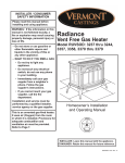
Radiance
Vent Free Gas Heater
Model RUVS40
WHAT TO DO IF YOU SMELL GAS
•
•
•
•
•
Shut off the gas supply.
Do not try to light any appliance.
Do not touch any electrical switch;
do not use any phone in your
building.
Immediately call your gas supplier
from a neighbor's phone. Follow
the gas supplier's instructions.
If you cannot reach your gas
supplier, call the fire department.
R AD
IAN
CE
Do not store or use gasoline or
other flammable vapors and
liquids in the vicinity of this or
any other appliance.
0456
WARNING: Improper installation, adjustment, alteration,
service or maintenance can cause
injury or property damage. Refer
to this manual for correct installation and operational procedures.
For assistance or additional information consult a qualified
installer, service agency, or the
gas supplier.
This is an unvented gas-fired heater. It
uses air (Oxygen) from the room
which it is installed. Provisions for
adequate combustion and ventilation
air must be provided.
Installation and service must be
performed by a qualified installer, service agency or the gas
supplier.
Homeowner’s Installation
and Operating Manual
Tested and listed to
ANSI Z21.11.2b-1998, Unvented Heaters
INSTALLER: DO NOT DISCARD THIS MANUAL LEAVE FOR HOMEOWNER
3000-0456c/1000
1
Vermont Castings Radiance
INSTALLER:
ATTENTION CONSUMER:
In order to ensure safe and effective
installation, this unit must be installed only by
a qualified agency, individual, firm, corporation,
or company that is experienced in the
installation, repair and servicing of this type of
appliance and is familiar with the building
codes and installation techniques appropriate
in your area. Contact your hearth products
dealer or local gas supplier for the name of a
qualified service person.
Please read this manual carefully before you
begin the installation procedures. Failure to
follow instructions may result in property
damage, bodily injury or loss of life. This
manual contains important user information.
Keep this manual with the fireplace after
installation is complete.
Table of Contents
Specifications ................................... 3
Safety Information ...........................4
General Information ......................... 5
Installation Requirements ............... 6
Assembly ..........................................9
Operation ..........................................15
Troubleshooting ...............................17
Maintenance ..................................... 19
Parts List ........................................... 21
2
Vermont Castings Radiance
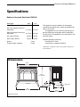
Specifications
Radiance Unvented Gas Heater RUVS40
Fuel Type:
NG
LP
Manifold Pressure; Min. / Max.: 1.7"/3.5"
Min. Inlet Supply Pressure for
adjustment::
5.4"/11.0"
5.0" W.C. 11.0" W.C.
Max. Inlet Supply Pressure for
adjustment:
8.0" W.C. 12.0" W.C.
Min. Output, BTU/hr:
26,000
26,000
Max. Output, BTU/hr:
35,000
35,000
Ignition :
Piezo
Firebox Weight / shipping:
175 lbs.
This appliance may be installed in an aftermarket*
manufactured (mobile) home, where not prohibited by
state or local codes.
This appliance is to be used only with the type of
gas specified on the rating plate which is attached to
the rear panel. This appliance is not convertible for use
with other gases.
Available Optional Accessories:
• Fan Kit #2767 / FK26
• Glass Panel / Catalyst Kit RGDCK
*Aftermarket: Completion of sale, not for purpose of resale, from
the manufacturer.
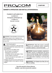
Dimensions
29³⁄₄"
(755.7mm)
RADIANCE
28¹⁄₄"
(717.6mm)
6¹⁄₂"
(165.1mm)
31"
(787.4mm)
Drawing Not to Scale
Supply Inlet
11"
(279.4mm)
18³⁄₈"
(466.7mm)
ST181
Fig. 1 Radiance Vent Free dimensions.
3
Vermont Castings Radiance
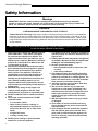
Safety Information
Warnings
IMPORTANT: Read this owner's manual carefully and completely before trying to assemble,
operate, or service this heater. Improper use of this heater can cause serious injury or death from
burns, fire, explosion, electrical shock, and carbon monoxide poisoning.
DANGER
CARBON MONOXIDE POISONING MAY LEAD TO DEATH!
Carbon Monoxide Poisoning: Early signs of carbon monoxide poisoning resemble the flu, with headaches,
dizziness, or nausea. If you have these signs, the heater may not be working properly. Get fresh air at once!
Have the heater serviced. Some people are more affected by carbon monoxide than others. These include
pregnant women, people with heart or lung disease or anemia, those under the influence of alcohol, and those
at high altitudes.
Make certain you read and understand all Warnings. Keep this manual for reference. It is your guide
to safe and proper operation of this heater.
1. Install only in accordance with National Fuel Gas
Code, ANSI Z223.1 - latest edition. (Exception:
Do not derate this appliance for altitude. This
appliance has been tested and listed for use in
altitudes up to 10,000 feet. Maintain the manifold
pressure at 3.5 inches W.C. for Natural Gas and
11 inches W.C. for LP gas.)
2. Use only the installation instructions provided
by the manufacturer for this appliance. Installation and repair should be done by a qualified
service person. The appliance should be inspected before use and at least annually by a
professional service person. More frequent
cleaning may be required due to excessive lint
from carpeting, bedding material, etc. It is
imperative that control compartments, burners
and circulating air passageways of the appliance
be kept clean.
3. WARNING: Any change to this heater or its
controls can be dangerous. DO NOT make
modifications to any heater or associated parts.
4. DO NOT install this heater in a bedroom or bathroom.
5. Due to high surface temperatures, DO NOT
install this heater
• in a recreation vehicle,
• where curtains, furniture, clothing, or
other flammable objects are less than 36
inches from the front, top, or sides of the
heater,
• in high traffic areas,
• in windy or drafty areas.
6. DO NOT place clothing or other flammable
material on or near the appliance.
4
7. This heater needs fresh, outside air ventilation to
operate properly. See Fresh Air Requirements on
pages 6 and 7.
8. If heater shuts off, heater may not have enough fresh
air ventilation. Provide more fresh air. If heater keeps
shutting off, see Troubleshooting, page 17.
9. DO NOT operate this heater
• where flammable liquids or vapors are used
or stored
• under dusty conditions.
10. The heater becomes very hot when operating.
Alert children and adults to stay away from hot
surfaces to avoid burns or clothing ignition. The
heater will remain hot for a time after shut-down.
Allow surface to cool before touching.
11. Carefully supervise young children when they
are in the room with the heater.
12. Do not use the heater if any part has been
exposed to or under water. Immediately call a
qualified service technician to inspect the room
heater and to replace any part of the control
system and any gas control which has been
under water.
13. DO NOT operate the heater if any log is broken
or damaged.
14. Turn heater off and let cool before servicing.
Only a qualified service person should service
and repair heater.
15. If so equipped, DO NOT operate this appliance
with the optional glass panel removed. If the
glass panel is removed from the appliance for
service or cleaning, it must be replaced before
operating the heater.
Vermont Castings Radiance
General Information
Vent Free Features
O H
I
L
Radiance
ON
PI
LO
T
OFF
Piezo Ignitor
Regulator
Valve Control
Radiance
ON
OT
PIL
OFF
The Radiance RUVS40 is an unvented gas heating
appliance tested and listed to the ANSI standard
Z21.11.2a 1997. This appliance is specifically configured
to burn either Natural Gas or Propane fuel, as indicated
on the metal rating plate attached to the rear shroud. The
Radiance RUVS40 is not fuel convertible.
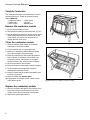
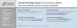
The Radiance burner controls are conveniently
located and easy to operate. As illustrated in Figure 1,
the front lip of the heater swings down to reveal the gas
valve controls and piezo pilot ignitor. Once the standing
pilot is lit, the heater can be set for either manual or
thermostatic operation using the convenient toggle
switch (Fig. 3) at the rear of the unit. A variable regulator allows you to adjust burner heat output between
HIGH, (35,000 BTU), and LOW, (26,000 BTU). See the
Operation section for details.
A push button Piezo ignitor is used to light the
standing pilot. The pilot incorporates an Oxygen
Depletion System (ODS/pilot) which will shut off gas
flow to the burner in the event that sufficient fresh air
becomes unavailable for continued safe operation.
ST174/183
Fig. 2 Radiance rating plate and control panel.
Quick Installation
Your Radiance Vent Free heater is shipped completely
assembled and ready for installation. You must,
however, locate the heater in accordance with the
specifications detailed in the next section of this
manual. Connection to the gas supply must be
made only by a qualified gas technician and only
after verification that the minimum combustion air
and ventilation requirements have been met.
T'STAT
OFF
ON
Optional Fan Kit #2767 /FK26
This accessory will help distribute heated air from
within the firebox out into the room. The fan is controlled by a snapstat that turns power on and off as the
firebox temperature rises above and falls below a
preset temperature. A rheostat provides for variable
fan speeds up to 160 cfm.
Optional
Glass / Catalyst Kit RGDCFK
ST182
Fig. 3 Remote burner switch.
The glass panel replaces the standard screen. The
catalytic combustor installs easily into the upper
manifold above the firebox. Ask your dealer for details.
5
Vermont Castings Radiance
Installation Requirements
WARNING
THIS HEATER MUST HAVE FRESH AIR FOR
PROPER OPERATION. IF NOT, POOR FUEL
COMBUSTION COULD RESULT. READ THE
FOLLOWING INSTRUCTIONS TO INSURE PROPER
FRESH AIR FOR THIS AND OTHER FUEL-BURNING
APPLIANCES IN YOUR HOME.
Fresh Air Requirements for
Combustion and Ventilation
Modern construction standards have resulted in homes
that are highly energy-efficient and that allow little heat
loss. Your home needs to breathe, however, and all
fuel-burning appliances within it require fresh air in
order to function properly and safely. Exhaust fans,
clothes dryers, fireplaces, and other fuel burning
appliances all use the air inside the building. If the
available fresh air is insufficient to meet the demands
of these appliances, problems can result.
The Radiance Unvented heater has specific fresh
air requirements. You must determine that these
fresh air requirements will be met within the space
where the appliance will be installed. The following
information will help you insure that adequate fresh air
is available for the heater to function properly.
Provide For Adequate Ventilation
Any space within a home can be classified in the
following categories:
1) Unusually Tight Construction
2) Confined Space
3) Unconfined Space
First, determine which classification defines the
intended space.
Unusually Tight Construction
You must provide additional fresh air if the space falls
into this classification. Unusually Tight Construction is
defined as construction wherein:
a. walls and ceilings exposed to the outside atmosphere have a continuous water vapor retarder with a
rating of one perm or less with openings gasketed or
sealed and
6
b. weather stripping has been added on openable
windows and doors and
c. caulking or sealants are applied to areas such as
joints around window and door frames, between sole
plates and floors, between wall-ceiling joints, between
wall panels, at penetrations for plumbing, electrical,
and gas lines, and at other openings.
If your home meets all of the three criteria above,
you must provide supplemental fresh air for the appliance from outside the home as detailed on page 7, B.
If your home does not meet the above criteria,
follow the procedure below.
Determine if You Have a Confined or
Unconfined Space
Use the following formula to determine if you have a
confined or unconfined space.
Space is defined as the room in which you will
install the heater plus any adjoining rooms with
doorless passageways or ventilation grilles between
the rooms.
The National Fuel Gas Code defines a confined
space as a space whose volume is less than 50 cubic
feet per 1,000 BTU per hour, (4.8 m3 per kw), of the
aggregate input rating of all appliances installed in that
space and an unconfined space as a space whose
volume is not less than 50 cubic feet per 1,000 BTU
per hour, (4.8 m3 per kw), of the aggregate input rating
of all appliances installed in that space. Rooms communicating directly with the space in which the appliances are installed, through openings not furnished
with doors, are considered a part of the unconfined
space.
1. Determine the volume of space, (length x width x
height). Include adjoining rooms connected by doorless
passageways or ventilating grilles.
Example:
A room that is 18' x 12' x 8' has a volume of 1728
cubic feet, ( length x width x height). An adjoining open
kitchen that is 10' x 12' x 8' has a volume of 960 cubic
feet. An adjoining open dining room is 12' x 12' x 8'
with a volume of 1152 cubic feet. The total space
volume is 3840 cubic feet. (1728 + 960 + 1152).
2. Divide the volume of space by 50 cubic feet.
The result is the maximum BTU/Hr that the space can
support.
Example:
3840 divided by 50 = 76.8 or 76,800 BTU/Hr.
Vermont Castings Radiance
3. Add the BTU/Hr ratings of all fuel-burning appliances installed in the same space, including the
following:
Gas Water Heater
Gas Furnace
Gas Fireplace Logs
Unvented Gas Heater
Vented Gas Heater*
Other Gas Appliances*
* Do not include Direct Vent appliances as these
utilize outside air for combustion and vent to the
outdoors.
Example:
Gas Range
Unvented Heater
Total
55,000 BTU/Hr
+33,000 BTU/Hr
88,000 BTU/Hr
4. Compare the maximum BTU/Hr rating the space can
support with the total BTU/Hr used by the appliances.
Example:
76,800 BTU/Hr - max. the space can support
88,000 BTU/Hr - total used by appliances
In this example, the maximum BTU/Hr that the
space can support is less than the total used by the
appliances, the space is considered to be Confined
space. Additional air must be provided to meet the
requirements of the Unvented heater.
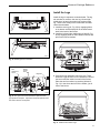
A confined space may be ventilated in two ways:
A) Open up or provide at least two ventilating grilles
to an adjoining unconfined space. Use any of the
options illustrated in Figure 4.
Each of the two grilles must provide an opening of
at least 50 square inches, with all opening dimensions
being at least 3". One grille must be located within 12"
of the ceiling; the other within 12" of the floor. (If the
total exceeds 100,000 BTU/Hr, additional grilles will be
required.)
B) Vent the room directly to the outdoors. (Provide
one square inch of opening for each 4,000 BTU/hr.
If the total BTU/Hr used by the appliances is less
than the maximum BTU/Hr the space is able to support, the room meets the Unconfined space criteria and
no further ventilation is required.
For further information on ventilation guidelines
and sizing specifications follow the National Fuel Gas
Code NFPA 54/ANSI Z223.1 Section 5.3.
WARNING
THIS HEATER SHALL NOT BE INSTALLED IN A
CONFINED SPACE UNLESS PROVISIONS ARE
PROVIDED FOR ADEQUATE COMBUSTION AND
VENTILATION AIR.
IF THE AREA IN WHICH THE HEATER MAY BE
OPERATED IS SMALLER THAN THAT DEFINED
AS AN UNCONFINED SPACE, PROVIDE
ADEQUATE COMBUSTION AND VENTILATION AIR
BY ONE OF THE METHODS DESCRIBED IN THE
NATIONAL FUEL GAS CODE, ANSI Z223.1, 1992,
SECTION 5.3.
12”
Option 2 Remove
Door
between
Adjoining
Rooms
Option 3 Vents to Adjoining
Room
Option 1
Vents to
Adjoining
Room
12”
ST184
Fig. 4 Vent options to provide additional air.
7
Vermont Castings Radiance
Clearance Requirements
Alcove Clearances
Minimum Clearances to Combustible
Materials
The Radiance Unvented heater may be installed in an
alcove constructed to maintain the clearances specified below.
Maintain clearance, (empty space), between combustible materials and the heater as specified below.
B
A
B
C
Freestanding Stove
D
A
B
D
C
ST103a
ST101
A: Maximum Mantel Depth .............. 7¹⁄₂" (190.5mm)
B: To Side Wall / Trim* ........................ 4" (101.6mm)
C: To Rear Wall ................................... 4" (101.6mm)
D: To Mantel / Trim* ... 16" (406.4mm) / 2" (50.8mm)
* Trim is 1" thick max.
A:
B:
C:
D:
Maximum Alcove Depth .............. 24" (609mm)
To Side Wall ................................... 4" (101mm)
To Rear Wall ................................. 4" (101mm)
To Ceiling ................................... 60" (1524mm)
Fig. 7 Alcove Clearances.
Hearth Requirements
The Radiance Unvented heater must be installed on
rigid flooring. If the appliance is installed on any
combustible surface other than wood flooring, such as
carpet or tile, a metal or wood panel must be installed
to extend the full length and width of the unit. There
are no other hearth or floor protection requirements.
Fig. 5 Freestanding Clearances.
A
B
WARNING
C
• Do not install this heater in a bathroom or
bedroom.
• Installation of this heater must conform with
local codes or, in the absence of local codes, with
the National Fuel Gas Code, ANSI Z223.1.
ST185
A = Depth, Mantel and/or Top Trim
B = Height from top of heater
C = Min. 10"
When:
A = 7¹⁄₂" (190mm) max.
B = 16" (406mm) min.
A = 3” (75mm) max.
B = 11¹⁄₂" (292mm) min.
A = 6" (152mm) max.
B = 14¹⁄₂" (368mm) min.
A = 1¹⁄₂" (38mm) max.
B = 10" (254mm) min.
A = 4¹⁄₂" (114mm) max.
B = 13" (330mm) min.
Fig. 6 Mantel Clearances.
8
• This heater creates warm air currents. These
currents move heat to wall surfaces next to the
heater. Installing the heater next to vinyl or cloth
wall coverings or operating the heater where
impurities in the air such as tobacco smoke exist,
may discolor walls.
• Do not use a blower insert, heat exchanger
insert or other accessory not approved for use
with this heater.
Vermont Castings Radiance
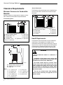
Assembly
Read these instructions thoroughly before starting
the assembly. Follow procedures in the order
given. Inspect the stove for damage before starting
the assembly. Do not install this stove if any
damage is evident. Contact your dealer immediately.
The Radiance is shipped on its back, mounted to a
wooden pallet. It is fully assembled, although packing
materials must be removed from the firebox and the
Log Set installed. Connection to the gas supply must
be performed only by a qualified gas technician who
should also verify that adequate ventilation is available
to support proper burner function.
Installation of optional accessories, such as the
Fan, Glass/Catalyst, or thermostat, is most easily
accomplished before the gas supply connection is
made.
Tools required
• Stub-handled Phillips screwdriver
• Standard Phillips screwdriver
• Standard flat-blade screwdriver
• Tape measure
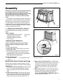
ST186
Fig. 8 Remove the front plate.
• work gloves
• knife
Unpacking the Radiance
Caution: Enamelled castings can chip easily!
Handle enamelled castings carefully to avoid
damage.
1. Cut the shipping straps.
2. Unpack the top grate and screen from the carton,
and set them aside.
3. With the help of an assistant, carefully remove the
stove from the pallet and move it close to its final
installed position. Lift the stove by the sides. Do not
lift by any part of the stove front.
Hardware Bag Contents
• Bag of Lava Rocks
• Door Handle & Screw
ST187ST188
Fig. 9 Release the latches and swing the screen and frame
away from the firebox.
• Wire Tie
Remove the Front, Screen and Logs
Remove the Front panel, the Screen panel, the Log
Set and hardware bag from the firebox before positioning the stove.
1. Remove the accessory package from the top of the
stove. The manual, hardware package, and lava
rocks are packed on top of the firebox. Set these
aside.
2. Remove the Front Plate. Grasp one side and the
bottom, and lift the front plate as a unit (the control
door attaches to the stove front). Swing the bottom
edge out and away from the stove body, (Fig. 8)
3. Remove the Screen Assembly. Two compression
latches hold the screen frame in place. (Fig. 9) Use a
screwdriver to release each latch by gently prying
the handle up and forward. Lift the screen frame
assembly up off the front of the firebox and set it
aside.
4. Remove the Log Set. Lift out the package and any
packing material from the burner tray and firebox.
Unpack the log set and inspect each piece for
damage. DO NOT INSTALL DAMAGED LOGS. Set
the logs aside out of the way.
9
Vermont Castings Radiance
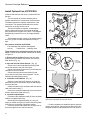
Install Optional Fan, #2767/FK26
Install the fan kit before the stove is connected to the
gas line.
The fan consists of a blower assembly and a
rheostat switch that are connected by a wire harness.
The blower attaches to brackets at the bottom of the
rear shroud. The rheostat installs within the remote
switch box, at the top left rear corner.
The fan kit includes a ‘snapstat’, a temperaturesensing switch which will be mounted to the blower
duct just below the top plate of the stove. The snapstat
automatically turns the fan on or off at approximately
109°F.
E
F
B
C
AA
D
A
A
B
D
The rheostat provides a range of fan speed settings
from OFF (which overrides the snapstat function) to
high.
H
Kit Contents used with the RUVS40:
G
ST189
• Fan assembly with rheostat and snapstat
• wire tie
• control knob
• retaining collar
Fig. 10 Open the rear shroud and install fan control switch.
These directions are oriented facing the rear of the
stove. Position the fan underthe rear shroud as shown
in Figure 10.
H
1. Remove the fan bracket. Remove the four sheet
metal screws (A) to detach the bracket (AA) from the
Rear Shroud. (Fig. 10)
2. Open the left side of Rear Shroud. (Fig. 10)
Pinch
grommet
to remove
G
ST190
• Remove the round head phillips screws (B) that
secure the shroud to the side of the stove.
• Remove the sheet metal screw (C) that fastens the
switchbox to the rear shroud.
• Remove the two sheet metal screws (D) that
secure the inner and outer shroud together. Let the
switchbox and wiring hang loosely.
ST191
Inner Shroud
Outer Shroud
3. Install the Control Switch. (Fig. 10)
• Run the control switch (E) and wire up along the
side between the inner and outer shrouds and through
the slot at the side.
• Attach the switch to the switch box with the retainer
collar and control knob (F).
• Secure the switch box assembly to the rear shroud
with the single sheet metal screw (C).
4. Connect Snapstat leads.
• Disconnect the snapstat module (G) from the leads
inside the snapstat bracket (H).
• Bend open the snapstat bracket (H). Use your
fingers or needle nose pliers to remove the black plastic
grommet from the bracket. Discard the bracket.
• Insert the grommet and wires into the large hole at
the bottom right corner of the inner shroud.
10
Grommet
ST192
Fig. 11 Remove the snapstat and grommet from the bracket
and insert the grommet into the inner shroud.
• Feed the snapstat wire leads through the grommet
into the stove interior. Connect the two wires to the two
snapstat extension leads attached to the inner shroud.
Vermont Castings Radiance
5. Resecure the Rear Shroud panels.
• Reinstall and tighten the two sheet metal screws
(D, Fig. 10) that secure the inner and outer shrouds
together.
• Secure the upper corner of the shroud and switch
box to the side of the stove using a 1/4 -20 x 1/2” round
head phillips screw, previously removed. (B, Fig.10)
Finally, replace the lower screw.
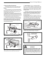
6. Attach the fan assembly to the bracket removed
earlier. Remove the sheet metal screws that secure the
finger guards at each end of the fan housing. Use these
screws to attach the fan to the bracket. (Fig. 12)
• Position the fan assembly so that the ducts slide
between the inner and outer shroud. The inner shroud
should engage with the two slots in the ends of the
bracket so that bracket and shroud are interlocked.
(Fig.14) Secure the bracket with the four sheet metal
screws previously removed.
7. Install snapstat. (Fig. 13) Looking through the
stove front, locate the snapstat mounting screws on the
side of the left air duct under the top plate. Remove the
front screw (A), but only loosen the rear screw. Slip the
snapstat under the rear screw, replace the front screw,
and tighten both.
• Detach the extension wire from the retainer clip at
the rear. Connect the female flag connectors (B) of the
snapstat extension to the snapstat module. Confirm
that the wires are running to the back and away from
the top of the stove.
8. Plug the power cord into a standard grounded 110volt household outlet. If the fan control knob is not turned
to the OFF position, the fan will turn on when the temperature at the snapstat reaches approximately 109°F.
Snapstat
Left Air Duct
B
Fan Bracket
A
ST195
Fig. 14 Install the snapstat and connect the extension wire
terminals. View is with top removed, however, access is
available through the grate opening in the top plate.
BLK
BLK
Fig. 12 Attach the fan assembly to the fan bracket.
BLK
{Inner Shroud}
SNAPSTAT
WHT
BLK
Slot
WHT
Outer
Shroud
Disconnect power
before servicing.
MOTOR
Finger Guard
GRN
ST193
ON/OFF
RHEOSTAT
POWER
Slot
ST196
Fig. 15 2767 / FK26 Fan Wiring Diagram
WARNING
ST194
Fig. 13 Position the fan to engage the inner shroud with the
fan bracket slots and secure with sheet metal screws.
The optional fan kit is equipped with a threeprong (grounding) plug for your protection against
shock hazard and should be plugged directly into
a properly grounded three-prong outlet. Do not
cut or remove the grounding prong from this
plug.
11
Vermont Castings Radiance
Thermostat Connection (optional)
Connect the Gas Line
Use only a millivolt rated thermostat. Check the table
below for the appropriate gauge thermostat wire to use
for the length of lead required in your installation.
Gas connection should be made in accordance with the
current edition of the National Fuel Gas Code, ANSI
Z223.1. Since some municipalities have additional local
codes, be sure to consult your local authority.
Thermostat
Wire Gauge
18
20
22
/ Maximum Run
40 feet
25 feet
16 feet
CAUTION
1. Install the wall thermostat in the desired location and
run the wires to the stove location. Terminate these
leads with 1/4" spade connectors.
2. Connect the thermostat wires to the two 1/4" female
connectors extending out of the control valve wire
harness. These wires are accessible from under the
left rear side of the stove. Either thermostat wire may
connected to either terminal. (Fig.16)
3. Place the control switch on the rear of the stove in
the “T’STAT” position and set the wall thermostat at
its lowest setting until the heater is ready for operation.
ST171
Fig. 16 Attach leads for an optional thermostat to the
connectors at the lower left rear corner of the stove.
• The gas line should be connected only by a
qualified gas technician. Test to confirm
manifold pressures as given below.
• There must be a gas shutoff valve installed
between the stove and the supply line.
With natural gas, use a 3/8” or 1/2” natural
gas supply line with an input of 35,000 BTUs at
a manifold pressure of 3.5” W.C. and minimum
inlet supply for adjustment of 5.0” W.C.
With propane, use a 3/8” or 1/2” propane
gas supply line with an input of 35,000 BTUs at
a manifold pressure of 11.0” W. C. and minimum
inlet supply for adjustment of 11.0” W.C.
1. Remove the valve coverplate. Use a stub handle
phillips screwdriver to loosen the two retainer screws
and pull the coverplate forward. (Fig. 17)
2. Connect the main gas supply line to the inlet on
the left side of the control valve. (Fig. 18)
The gas line connection can be made with properly
tinned 3/8” copper tubing, 3/8” rigid pipe, or an
approved flexible connector. When using copper or
flexible connectors, use only approved fittings.
Always provide a union so the gas line can be easily
disconnected for burner service.
3. Test for leaks at all joints with a 50/50 solution of
liquid soap and water to test for leaks at gas fittings
and joints. Apply water/soap solution with a brush
only - do not over apply. NEVER! test with an open
flame.
4. Reinstall the coverplate over the control valve by
engaging the slots on the back of the plate, with the
retainer screws. Retighten the screws.
5. Light the pilot according to the directions on pages
15-16 . It may take several minutes to fully bleed the
5-gas line of any air.
When you have confirmed that the pilot lights properly,
shut it off and complete the installation.
12
Vermont Castings Radiance
Install the Logs
PILOT
ADJ
I
PI
L
ON
O H
LO
T
OFF
ST172
Fig. 17 Remove the valve cover plate.
Install the logs in sequence as shown below. The log
set includes six sections: the rear log, left and right
middle logs, left and right ember logs, and an upper
log. There is also a bag of lava rocks which simulate
charcoal and embers.
1. Install the rear log (#1, Fig. 20) by engaging holes
on its bottom surface with pins on the sheet-metal
shelf at the back of the firebox.
2. Install the left and right middle logs (#2 and #3, Fig.
20) by engaging holes on their bottom surfaces with
pins on the burner brackets.
PILOT
ADJ
I
OT
PIL
L
ON
O H
OFF
2
3
1
ST173
Fig. 18 Flexible gas line connection.
Brackets
ST142
On/Off
Control
Knob
Pilot
Adjustment
Screw
Fig. 20 Install rear and middle logs.
Regulator
PILOT
ADJ
3. Push the burner assembly fully to the rear. There
should be a gap of about 13/16” between the front of
the burner and the inside front wall of the firebox.
Place the two front ember log sections (#4 and 5,
Fig. 21) in the slot at the front of the firebox, just in
front of the burner.
I
L
ON
TPTH
O H
LO
PI
T
TP
OFF
TH
Pressure Tap
Piezo
Ignitor
HV100
Fig. 19 The gas control valve includes a captured screwtype pressure test point. A pressure test point upstream from
the control valve is not required.
5
4
ST143
Fig. 21 Install the front ember logs.
13
Vermont Castings Radiance
4. Loosely sprinkle the lava rocks (#6) directly on top
of the burner, between the front and middle logs. Do
not place any ember or lava material behind the
middle logs. (Fig. 22)
7
6
ST144
Fig. 22 Install the lava rocks and top log.
5. Engage the sockets in the underside of the top log
(#7) with the pegs on the rear log and the left middle
log as shown in Figure 22. Ensure that the top log is
positioned properly, relative to the right middle log,
as shown in Figure 23.
Complete the Installation
1. Replace the screen frame or glass frame assembly by resting the bottom edge of the frame on
support brackets below the front opening of the
firebox. Swing the top edge of the assembly toward
the firebox, and center it. Fasten it by closing the
latches over the top left and right edges of the frame.
2. Replace the stove front by grasping it by the left
and right edges. Lift it so that tabs on the back side
of the top corners engage notches at the top forward
corners of the stove sides. Then gently swing the
bottom of the front panel to a vertical position, and
lower it till prongs on its bottom left and right corners
engage with notches cast into the tops of the forward
legs. (Fig. 24) Test that the front is installed securely
by grasping two of panel’s vertical bars, and pulling
the panel toward yourself. When the panel is in
place properly you should not be able to pull the
bottom of the front toward yourself without also lifting it.
3. Attach the wooden handle to the control door using
the #8-32 x 2” screw from the parts bag. (Fig. 25)
4. Set the screen and the cast-iron grate into the
recess in the stove top.
This completes the installation and assembly of the
Radiance RUVS40.
3¹⁄₂”
(88.9mm)
ST135a
Fig. 24 Replace the front panel.
ST145a
Fig. 23 Confirm that the top log is properly located by
measuring 3¹⁄₂ inches from the left inside wall of the firebox to
the end of the left branch of the top log.
ST197
Fig. 25 Attach the handle to the control door.
14
Vermont Castings Radiance
Operation
Pilot and Burner Inspection
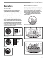
Your First Fire
Read these instructions carefully and familiarize
yourself with the burner controls of this heater.
The Radiance uses a Honeywell control valve that
allows thermostatic regulation. A separate Piezo ignitor
generates a spark at the pilot orifice when the button is
pushed. Figures 26 - 30 illustrate the operating
positions for the RUVS40 controls.
Each time you light your Radiance, check that the pilot
flame and burner flame pattern appear as in Figures 31
and 33. If flame patterns are incorrect, turn the heater
off and use the procedures in the Troubleshooting
section of this manual to determing a solution. Do not
operate the heater until the pilot flame is correct.
Follow regular maintenance procedures as described on page 17.
Set the 3-way burner control switch on the back of
the appliance to the OFF position (midpoint). Locate
the Pilot assembly on the right side behind the burener.
(Fig. 31) Follow the lighting instructions on page 16
exactly. Use the regulator control to adjust heat output.
During the first fire, it is not unusual to smell some
odor associated with new logs, paint and metal being
heated. Odors should dissipate within a few hours or
so, however, you can open a window to provide plenty
of fresh air to alleviate this condition.
ST198
Fig. 31 Proper pilot flame appearance.
ON
T
LO
PI
OFF
HV107
HV106
Fig. 26 Pilot position.
Pilot can be lit.
Fig. 27 Piezo button.
ST199
ON
Fig. 32 Pilot Assembly Location.
T
LO
PI
T'STAT
OFF
ON
OFF
HV108
Fig. 28 Burner is
functional.
ST175
LO
HI
Fig. 29 Burner control
switch.
ST200
HV109
Fig. 33 Proper burner flame pattern.
Fig. 30 Regulator range.
15
Vermont Castings Radiance
FOR YOUR SAFETY READ BEFORE LIGHTING
WARNING: IF YOU DO NOT FOLLOW THESE INSTRUCTIONS EXACTLY, A FIRE OR
EXPLOSION MAY RESULT CAUSING PROPERTY DAMAGE, PERSONAL INJURY, OR
LOSS OF LIFE.
A. This appliance has a pilot. When lighting the pilot, follow these instructions exactly.
B. BEFORE OPERATING smell all around the appliance area for gas. Be sure to smell next to the floor
because some gas is heavier than air and will settle on the floor.
WHAT TO DO IF YOU SMELL GAS.
• Shut off the gas supply.
• Do not try to light any gas appliance.
• Do not touch any electric switch; do not use any phone in your building.
• Immediately call your gas supplier from a neighbor’s phone. Follow the gas supplier's instructions.
• If you cannot reach your gas supplier, call the fire department.
C. Use only your hand to turn the gas control knob. Never use tools. If the knob will not turn by hand, don't
try to repair it. Call a qualified service technician. Force or attempted repair may result in a fire or explosion.
D. Do not use this appliance if any part has been under water. Immediately call a qualified service technician to inspect the appliance and to replace any part of the control system and any gas control that has
been under water.
LIGHTING INSTRUCTIONS
CONTROL
KNOB
1. STOP! Read the safety information above on this panel.
2. If applicable, turn thermostat to lowest setting or set burner switch to "OFF" position.
ON
3. Push in gas control knob slightly and turn clockwise
to "OFF."
T
LO
PI
OFF
NOTE: Knob cannot be turned from "PILOT" to "OFF" unless knob is pushed in slightly. Do
not force.
HV103
4. Wait five (5) minutes to clear out any gas. If you then smell gas, STOP! Follow "B" in the safety information above on this panel. If you don't smell gas, go to the next step.
5. Turn knob on gas control counterclockwise
to "PILOT." Push in control knob all the way and hold
in. Immediately light the pilot by pushing the square ignitor button. Continue to hold the control knob in for
about one (1) minute after the pilot is lit. Release knob and it will return back up. Pilot should remain lit. If
it goes out, repeat steps 3 through 5.
6. • If knob does not pop up when released, stop and immediately call your service technician or gas supplier.
• If the pilot will not stay lit after several tries, turn the gas control knob clockwise
your service technician or gas supplier.
7. Turn gas control knob counterclockwise
to "OFF" and call
to "ON."
8. Set the burner control switch to "ON" or set to "T'STAT" and adjust wall thermostat.
ST198a
PILOT LIGHT
TO TURN OFF GAS TO APPLIANCE
1. Set the burner control switch to "OFF" if service is to be performed.
2. Push in gas control knob slightly and turn clockwise
to "OFF." NOTE: Knob cannot be
turned from "PILOT" to "OFF" unless knob is pushed in slightly. Do not force.
16
Vermont Castings Radiance
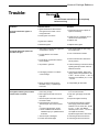
Trouble-
Warning
Turn OFF heater and allow to cool completely
before servicing.
Condition
Possible Cause
Solution
No spark at Pilot when Ignitor is
operated
1.Ignition Electrode is disconnected
from ignition wire, broken o incorrectly positioned.
1. Inspect and reconnect, replace or
repair as necessary.
2. Piezo Ignitor nut is loose.
2. Tighten the nut to establish secure
contact to the valve bracket.
3. Ignitor wire is broken.
3. Replace wire.
4. Bad Piezo Ignitor.
4. Replace Piezo ignitor.
1. Gas supply is turned off or supply line
shutoff valve is closed.
1. Turn on gas supply or open suppy
line shutoff valve.
2. Control KNob is not in PILOT
position.
2. Turn Control Knob to PILOT.
3. Contol Knob not pressed in while in
PILOT position.
3. Press Control Knob in while in the
PILOT position.
4. Air present in gas lines.
4. Continue holding in Control Knob and
repeat ignition procedure until air is
bled from the lines.
5. Inlet supply pressure is not within
correct settings.
5. Call local gas supplier. Adjust inlet
supply pressure to specification: NG;
5” W.C. - 8” W.C. (5”W.C. - 7” W.C. at
elevations over 8000 ft.) LP; 11” W.C.
- 12” W.C.
6. Other conditions that should be
identified only by a qualified gas
technician.
6. Call qualified gas technician.
1. Control Knob not fully depressed or
held in long enough.
1. Depress Control Knob fully and hold
in for a full 30 seconds.
2. Gas supply line shutoff valve is not
fully open.
2. Fully open gas supply line shutoff
valve.
3. Thermocouple connection is loose at
the Control Valve.
3. Inspect and tighten securely.
4. Pilot flame does not touch the
Thermocouple. This can be caused
by:
a. Incorrect gas pressure, and/or
b. other conditions that should be
identified only by a qualified service
technician.
4. A) Contact the local gas company.
Inlet supply pressure should be
between 5” W.C. and 8” W.C. for NG
(5” W.c. - 7” W.C. over 8000 ft
elevation) and 11” W.C. - 12” W.C. for
LP. Adjust as necessary.
7. Thermocouple is damaged.
5. Call local gas service technician.
8. Control Valve is damaged.
6. Call local gas service technician.
The Iignitor Electrode sparks, but
Pilot does not light
Pilot lights but flame goes out when
Contorl Knob is released.
B) Call local gas service technician.
17
Vermont Castings Radiance
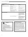
Troubleshooting (continued)
Condition
Possible Cause
Solution
Pilot lights but Main Burner does not
1.Gas supply line shutoff valve is
not fully open.
1.Fully open gas supply line shutoff
valve.
2.Foreign material is blocking
Burner ports.
2.Inspect and clear debris away
from Burner ports.
3.Main Burner orifice is clogged.
3.Call local gas service technician.
4.Thermostat or remote switch not
activated on RUVS40.
4.Set thermostat to higher temperature or check remote switch.
1.Insufficient fresh air.
1.Determine that adequate ventilation exists to provide sufficient
fresh air. Open a window or
provide additional ventilation.
(See Fresh Air Requirements,
page 4-5)
2.Incorrect inlet supply pressure.
2.Contact the local gas company.
Adjust inlet supply pressure to
specification: NG; 5” W.C. - 8”
W.C. (5” W.C. - 7” W.C. at
elevations over 8000 ft.) LP; 11”
W.C. - 12” W.C.
Main Burner shuts off and Pilot flame
goes out while in operation
Warning
•
•
•
•
•
•
If you smell gas:
Shut off gas supply
Do not try to light any appliance
Do not touch any electrical switch; do not
use any phone in your building.
Immediately call your gas supplier from a
neighbor’s phone. Follow the gas supplier’s
instructions.
If you cannot reach your gas supplier, call the
fire department.
Odor During Operation
Neither natural gas nor LP gas give off an odor when
burned. The nature of a vent free combustion
system, however, is such that odors may occasionally be produced during heater operation when
impurities exist in the immediate area. Cleaning
solutions, paint, solvents, cigarette smoke, adhesives, new carpet or textiles, etc., all can create
fumes. These fumes may mix with combustion air
and can create odor. Such odors will disappear over
time, however, the condition can be alleviated by
opening a window or otherwise providing additional
ventilation to the area.
If odors persist and you are unable to locate the
source, contact a qualified gas service technician.
18
Vermont Castings Radiance
Maintenance
Your Radiance Vent Free heater will provide years of
service with minimal upkeep. The following procedures
will help ensure that your heater continues to perform
safely and efficiently.
Firebox Cleaning and Inspection
Cleanliness is critical to correct operation of the
heater. The log set, burner, valve controls and air
circulation areas must all be kept free of dust and
unobstructed by debris. Inspect these areas before
each use and clean whenever accumulation is
evident. Follow the simple procedure outlined below.
Frequent cleaning may be necessary in living
environments subject to excessive carpet lint or pet
hair. For example, if you live with a dog that sheds
continuously, you will need to inspect the burner area
frequently and clean it as often as the accumulation
requires. In extreme conditions, it may be necessary
to clean the burner and log set monthly or biweekly.
This appliance should be inspected and thoroughly cleaned annually by a qualified gas technician.
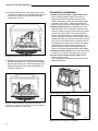
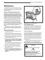
Cleaning Procedure
1. Turn the burner OFF and let the heater cool completely before cleaning.
2. Lift the Front plate up and then swing the bottom out
to disengage it from the heater shell. (Fig. 8, page 9)
3. Remove the screen or glass panel by releasing the
two upper retainer latches (A). Lift the panel up and
off of the firebox frame. (Fig. 34)
4. Carefully inspect the log set for damage. Contact
your local dealer if any damage is evident. DO NOT
OPERATE THE HEATER WITH A DAMAGED OR
LOOSE LOG SET.
Use a soft-bristled brush vacuum cleaner attachment to remove dust or debris from the log set, pilot
and burner. Use care as the log set is fragile.
5. Inspect the catalytic combustor at the top of the
firebox. Replace the combustor if any damage or
deterioration is evident.
6. Replace the screen or glass panel and the front
plate. DO NOT OPERATE THE HEATER WITH THE
SCREEN / GLASS PANEL OR FRONT PLATE
REMOVED.
ST202/203
Fig. 34 Remove the screen or glass panel.
Glass Replacement
If so equipped, do not operate this appliance with the
glass panel cracked, broken, or removed. Replace
damaged glass only with Vermont Castings ceramic
glass panel Part No. 160-1290. Follow the Cleaning
Procedure instructions regarding parts removal.
Care of Cast Iron
An occasional dusting with a dry rag will help keep the
painted surfaces looking new. Use high-temperature
stove paints, available through your local dealer, to
touch-up areas as needed. Clean areas to be painted
with a wire brush and be sure to cover the log set,
burner and valve assembly. Apply the paint sparingly;
two light coats of paint will give better results than a
single heavy coat.
Porcelain enamel surfaces should be cleaned with
a soft, damp cloth. Do not use abrasive cleaning
agents. If necessary, use only a cleaning agent formulated specifically for use on porcelain enamel surfaces.
WARNING
Turn the burner Pilot OFF before applying
paint.
WARNING
Dust and debris accumulation can result in
poor performance. Inspect the Valve
compartment, burner parts and log set
frequently and Clean these parts monthly or as
often as accumulation warrants.
19
Vermont Castings Radiance
Catalytic Combustor
The combustor should be cleaned annually to ensure
optimal performance. Follow the procedure below.
Tools / Materials:
• phillips screwdriver
• baking soda
• white vinegar
• rubber gloves
• tap water
• distilled water
Remove the combustor module
1. Be sure that the heater is COLD.
2. Remove the front plate, top grille and screen. (Fig. 35)
3. Use the phillips screwdriver to remove the two sheet
metal screws that secure the combustor to the top
of the firebox. (Fig. 36) Lift the unit up and out
through the front of the stove.
Clean the combustor module
ST186
Fig. 35 Remove the front plate and top grille/screen.
1. Obtain a container large enough to completely
submerge the combustor module.
2. Fill the container with 13 cups of tap water.
3. Measure 11 tablespoons baking soda and slowly
pour it into the water, mixing thoroughly.
4. Place the combustor into the solution and allow to
soak for fifteen (15) minutes. If the module is not
completely covered, follow steps 1-3 to prepare
enough solution to fully submerge the combustor.
5. Rinse the combustor with tap water.
6. Dump the solution and thoroughly rinse the container.
7. Fill the container with enough white vinegar to
submerge the combustor module.
8. Place the module into the container and allow it soak
for fifteen (15) minutes.
9. Rinse the module with distilled water.
10. Lightly shake the catalytic module to expel excess
water. Allow to air dry.
Replace the combustor module
1. Slide the combustor through the front opening of the
stove and insert it into the housing on top of the
firebox. Secure with the two sheet metal screws.
2. Replace the glass panel and front.
20
ST201
Fig. 36 Remove the catalytic combustor module.
Vermont Castings Radiance
1
2
3
54
19
20
60
52
60
18
7
57
55
55
9
8
56
21
56
52
7
4
8
22
6
57
23
51
51
53
53
10
16
16
12
11
58
43
13
17
15
41
37
33
44
5
14
57
52
53
51
45
42
38
52
39
55
25
29
36
40
62
35
34
53
26
28
58
48
51
27
30
31
53
46
47
53
51
49
32
53
57
61
50
0456
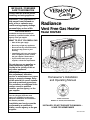
The Vermont Castings, Majestic Products Company reserves the right to make changes in design, materials, specifications, prices and discontinue colors
and products at any time, without notice.
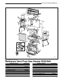
Radiance Vent Free Gas Heater RUVS40
1.
2.
3.
4.
5.
6.
7.
8.
9.
10.
Item/Model Number
Grille
Grille Screen
Top
End, Left
End, Right
Rear Shroud, Outer
Duct Cap
Duct Base
Heat Shield
Flue Collector
Part Number
1301192
1601933
1301186
1301234
1301189
20000862
20000875
20000876
20000877
20000858
11.
12.
13.
14.
15.
16.
17.
18.
19.
20.
Item/Model Number
Right Latch Bracket
Left Latch Bracket
Back Log Bracket
Right Log Bracket
Left Log Bracket
Screen / Glass Frame, Latch (2)
Screen Frame Assembly
Switch Box
Switch, ON/OFF/T'STAT
Rheostat Plug
Part Number
20000859
20000860
20000991
1409173
30000109
1601992
20000883
1408791
1601597
1600561
21
Vermont Castings Radiance
RUVS40 (Continued)
Part Number
1208618
1201504
1601913
30000453
20000853
20000856
20000854
20000855
30000037
20000880
20000881
57897
30000446
20000663
30000449
30000518
30000332
20000130
1601929
1601930
1409110
40.
41.
42.
43.
44.
45.
46.
47.
48.
49.
50.
51.
52.
53.
54.
55.
56.
57.
58.
59.
60.
61.
Item/Model Number
Ignition Cable
Pilot Bracket
Pilot Tubing
Firebox
Bottom
Control Panel
Front
Cable, Control Door
Spring, Control Door
Control Door
Control Door Handle, Wood
Handle Stub
Damper Tab (8)
1/4-20 x 3/8" Phillips Screw (13)
1/4-20 x 1/2" Hex Head Screw (10)
1/4-20 x 1¹⁄₄" Stud, Top Plate (4)
Flat Washer, 1/4", 7/8 O.D. (12)
1/4-20 x Hex nut, Top to Sides (5)
Flat Washer, 1/4" Blk (5)
1/4-20 x 1" Leg Levelling Bolt (4)
#10 x 1/2" Pan Hd
Sheet Metal Screw (39)
8-32 x 2" Rnd Hd Slotted Screw(1)
#10-24 X 1/4" Phil. Pn Hd Screw (4)
Part Number
20000101
20000851
30000448
1301148
30000328
1409136
1301229
1601924
1201842
1301220
1600660
1601981
1601488
1200993
1201338
1204212
1202470
1203210
1202473
1201745
1202058
1201243
120 0980
10000235
1000-0242
For replacement parts, or for information about parts or
service, contact your local Vermont Castings, Majestic
Products Company Authorized Dealer. For the name of
the dealer nearest you, call or write:
The Vermont Castings,
Majestic Products Company
410 Admiral Blvd.
Mississauga, Ontario, Canada L5T 2N6
905 670-7885
T'STAT
ON
Label
OFF
Item/Model Number
21. Wire Clip
22. Wire Tie,
Wire Harness/Rear Shroud
23. Wire Harness,
Burner / Thermostat
24. Wire Harness,
Snapstat Extension (not shown)
25. Gas Log Set
26. Back Log
27. Right Middle Log
28. Left Middle Log
29. Top Log
30. Left Front Ember Log
31. Right Front Ember Log
32. Lava Rocks
33. Burner Assembly
34. Manifold Tube Assembly
35. Orifice Hood, Front - NG (#51)
Orifice Hood, Front - LP (#60)
36. Orifice Hood, Rear - NG (#42)
Orifice Hood, Rear - LP (#54)
37. Pilot, ODS w/TP-OP #84210 - NG
Pilot, ODS w/TP-OP #84210 - LP
38. Valve Bracket
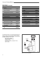
39. Control Valve, Honeywell 8421
NG
LP
THERMOPILE
WHITE
THERMOSTAT
(OPTIONAL)
WHITE
BLACK
RED
TAN
TP/TH
TP
SIT
Gas Valve
TH
RED
ST204
Fig. 37 RUVS40 Wiring Diagram
22
Vermont Castings Radiance
Warranty
Limited Three Year Warranty
The Vermont Castings, Majestic Products Comany
warrants that this Radiance Natural Vent Room Heater
will be free of defects in material and workmanship for a
period of three years from the date you receive it, except
that the glass door panel, ceramic logs, and gasketing
shall be warranted for one year as described below.
The Vermont Castings, Majestic Products Company will repair
or replace, at its option, any part found to be defective upon
inspection by a Vermont Castings, Majestic Products Company Authorized Dealer. The customer must return the
defective part or the stove, with shipping prepaid, to the
Authorized Dealer or pay for any Authorized Dealer in-home
travel fees or service charges for in-home repair work. It is the
dealer’s option whether the repair work will be done in the
customer’s home or in the dealer’s shop. If, upon inspection,
the damage is found to be the fault of the manufacturer,
repairs will be authorized at no charge to the customer for
parts and/or labor.
Any Radiance Natural Vent Room Heater or part thereof that is
repaired or replaced during the limited warranty period will be
warranted for a period not to exceed the remaining term of the
original limited warranty or six (6) months, whichever is longer.
Limited One Year Warranty
The following parts of the Radiance Natural Vent Room Heater
are warranted to be free of defects in material and workmanship for a period of one year from the date you receive it.
These parts are the glass panel, ceramic logs, and gasketing.
Any of these items found to be defective will be repaired or
replaced at no charge, upon the return of said part to a
Vermont Castings, Majestic Products Company Authorized
Dealer with postage prepaid.
Exclusions and Limitations
1. This warranty is transferable; however, proof of original purchase is required.
2. The Vermont Castings, Majestic Products Comany offers no
warranty on chipping of enamel surfaces. Inspect your Radiance
Room Heater prior to accepting it for any damage to the enamel.
3. This warranty does not cover misuse of the Radiance Natural
Vent Room Heater as described in the Homeowner’s Installation
and Operating Manual, nor does it cover a Radiance Natural Vent
Room Heater that has been modified unless authorized by a
Vermont Castings, Majestic Products Company representative in
writing.
4. This warranty does not cover a stove repaired by someone
other than either a Vermont Castings, Majestic Products Company Authorized Dealer or an authorized, qualified gas agency.
5. Damage to the unit while in transit is not covered by this
warranty but is subject to claim against the common carrier.
Contact The Vermont Castings, Majestic Products Company
Authorized Dealer from whom you purchased your Radiance
Room Heater. (Do not operate the Radiance Room Heater as this
may negate the ability to process the claim with the carrier.)
6. Claims are not valid where the installation does not conform
to local building and fire codes or, in their absence, to the
recommendations in the Homeowner’s Installation and Operating Manual.
7. The Vermont Castings, Majestic Products Company shall
have no obligation to enhance or update any unit once
manufactured.
IN NO EVENT SHALL THE VERMONT CASTINGS, MAJESTIC PRODUCTS COMPANY BE LIABLE FOR INCIDENTAL
AND CONSEQUENTIAL DAMAGES. ALL IMPLIED WARRANTIES, INCLUDING THE IMPLIED WARRANTIES OF MERCHANTABILITY AND FITNESS, ARE LIMITED TO THE
DURATION OF THIS WRITTEN WARRANTY. THIS WARRANTY SUPERSEDES ALL OTHER ORAL OR WRITTEN
WARRANTIES.
Some states do not allow the exclusion or limitations of
incidental and consequential damages or limitations on how
long an implied warranty lasts, so the above limitations may
not apply to you. This warranty gives you specific rights and
you may have other rights which vary from state to state.
8. The salt air environment of coastal areas or a high humidity
environment can be corrosive to the porcelain enamel finish.
These conditions can cause rusting of the cast iron beneath
the porcelain enamel finish which will cause the porcelain
enamel finish to flake off.
How To Obtain Service
If a defect is noted within the warranty period, the customer
should contact a Vermont Castings, Majestic Products
Company Authorized Dealer with the following information:
1. Name, address, and telephone number of the purchaser.
2. Date of purchase.
3. Serial number from the label on the back of the stove.
4. Nature of the defect or damage.
5. Any relevant information or circumstances, i.e., installation,
mode of operation when defect was noted.
A warranty claim process will then begin. The Vermont
Castings, Majestic Products Company reserves the right to
withhold final approval of a warranty claim pending a visual
inspection of the defect by authorized representatives.
INSTALLER:
Please record the following information
for future reference.
Appliance Serial No. _____________________________
Appliance Type: NG ____
LP ____
Inlet Supply Pressure: ____________________________
Manifold Pressure: ______________________________
Dealer ________________________________________
_______________________________________________
Phone _______________________________________
Installer _______________________________________
_______________________________________________
Phone _________________________________________
Date Installed _______________________________
23
Vermont Castings Radiance
The Vermont Castings,
Majestic Products Company
410 Admiral Blvd. • Mississauga, Ontario, Canada L5T 2N6 • 905-670-7885
www.majesticproducts.com • www.vermontcastings.com
© The Vermont Castings, Majestic Products Company
24