1
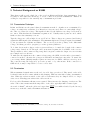
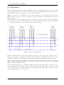
5
Technical Background on RS485
5 Technical Background on RS485
This chapter will provide a little bit of theory about RS422 and RS485 data transmission. It is
necessary to have this basic knowledge, to avoid or find errors in data transmission. Failures in
cabling are responsible for the vast majority of transmission problems.
5.1 Transmission Technique
RS422 and RS485 use the same balanced transmission method. Signals are not transmitted by
voltage on a single wire, as RS232 does. Instead two wires are used; when one carries high voltage,
the other one carries low voltage. The signal is defined by the difference in voltage between those
two wires. This hardens the transmission against noise. Usually twisted pairs are used, which
further reduces the sensitivity for noise.
Typical voltages are +4V as high, about +0.5V as low. These voltages are generated and defined
against the GND signal of the transmitter. The minimum differential voltage is required as ±200mV
by the specifications of RS422 and RS485. The receiver detects the polarity of the differential
voltage, and thus gets a Zero (negative) or a One (positive) difference.
To do this detection the voltages on the receivers side have to be inside the bounds of the common
voltage range defined as -7V through +12V, as measured against the local GND of the receiver.
The specification of the common voltage range has been given to make the design of receiver circuits
more simple and cost effective.
To make sure the signals meet the common voltage range, the GND of sender and receiver must be
connected somehow, otherwise the voltages are undefined and may have any value. To assure the
correct range RS485 (RS422) usually requires an extra wire for GND2 , which is often forgotten.
The connection may also happen by protective ground, or by other means. If the connection of
GND is bad, it may be impossible to receive correct data.
5.2 Termination
When transmitted signals arrive at the end of a cable, they get reflected. They travel on the cable
back and forth some more times, which is called ringing. This can cause false reading of transmitted
data. When the reflections travel on the cable several times, they are damped and do no longer
cause errors. This happens earlier if the cables are short.
For long cables Termination Resistors are required. These increase the damping of reflections. The
value of the resistor must match the impedance of the cable, typically 120Ω for twisted pair.
As a rule of thumb3 , when the cables are longer than 1000000
Bitrate (one million divided by the bit rate)
in meters, you should consider Termination Resistors.
2
3
with an optional resistor
Assuming group speed of 100.000km/s, 10 travels to damp out, and 10% of bit time
June 2009
USB-COM PRO User Manual
27