1
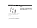
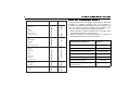
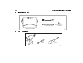
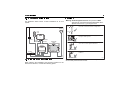
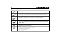
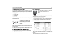
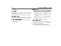
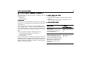
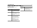
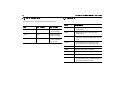
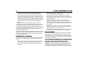
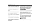
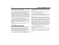
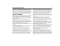
Raymarine
AIS250 Receiver
User’s Guide
Document Number: 81286_1
Date: February 2007
Trademarks and registered trademarks
Autohelm, HSB, Raymarine, RayTech, Sail Pilot, SeaTalk and Sportpilot are registered trademarks of Raymarine Limited. Apelco is
a registered trademark of Raymarine Holdings Limited (Registered in all major marketing territories).
AST, Autoadapt, Auto GST, Autoseastate, Autotrim, Bidata, Marine Intelligence, Maxiview, On Board, Raychart, Raynav, Raypilot,
Raystar, ST40, ST60, Seaclutter, Smart Route, Tridata and Waypoint Navigation are trademarks of Raymarine Limited.
All other product names mentioned are trademarks or registered trademarks (if applicable) of their respective companies.
© Raymarine plc 2007
Contents
i
Contents
Safety notices....................................................... 1
Important information ............................................ .3
Introduction .......................................................................
Intended use ......................................................................
Compatibility ......................................................................
Warranty ............................................................................
EMC conformance .............................................................
Waste Electrical and Electronic Equipment Directive ........
Restriction of the use of certain Hazardous Substances ...
Handbook information........................................................
What is AIS? ......................................................................
Classes of AIS ...................................................................
Static and dynamic information..........................................
3
3
3
4
4
4
4
4
5
5
6
Installation.............................................................. .9
EMC installation guidelines .............................................. 9
Items in the box............................................................... 10
Tools required ................................................................. 10
System configuration ...................................................... 11
Planning the installation .................................................. 11
Receiver........................................................................... 11
Antenna ........................................................................... 12
Cable runs....................................................................... 12
Power cable ..................................................................... 12
Antenna cable.................................................................. 12
Installing the system ....................................................... 13
Receiver........................................................................... 13
Cable connections .......................................................... 14
AIS250 cable connections. .............................................. 14
AIS250 integrated NMEA multiplexer .............................. 15
Power............................................................................... 15
Using the AIS application..................................... .19
Introduction......................................................................
Selecting the correct baud rate for your AIS application .
Selecting the AIS function ...............................................
AIS status Indicators ........................................................
Setting up AIS .................................................................
How AIS data is displayed?.............................................
AIS Target symbols .........................................................
Viewing target information ...............................................
AIS safety data.................................................................
AIS target list....................................................................
Target list .........................................................................
Full AIS data ....................................................................
Using AIS for collision avoidance ....................................
Safe zones .......................................................................
Safety messages .............................................................
Simulator..........................................................................
19
19
19
19
20
21
22
23
23
23
24
24
25
25
26
26
Troubleshooting & Glossary................................. .27
Troubleshooting............................................................... 27
LED sequence................................................................. 28
Glossary .......................................................................... 28
Raymarine World Wide Warranty.......................... .29
1. Product warranty..........................................................
2. Onboard warranty ........................................................
3.Obtaining warranty service ...........................................
4. Warranty limitations .....................................................
31
31
32
33
ii
Raymarine AIS250 Receiver - Users Guide
Chapter 1: Important information
Chapter 1: Important information
3
Disclaimer
1.1 Introduction
D10106_1
All information presented by the Raymarine AIS receiver is advisory only. You acknowledge the risk of incomplete and
erroneous information and assume complete responsibility and
risks associated with this device, and accordingly release
Raymarine, Weatherdock and Dommel from any and all claims
arising from the use of this service.
This guide contains an explanation of how to install, commission, maintain and use your Raymarine AIS250 Receiver.
Intended use
This product is an Automatic Identification System (AIS)
receiver. The intended application is as one component of a
navigation system for recreational and commercial vessels not
covered by IMO/SOLAS carriage requirements.
Compatibility
This product has been designed to be compatible with Raymarine C and E-Series products and other systems that support
AIS.
4
Raymarine Automatic Identification System Receiver
Warranty
To register your new Raymarine product, please take a few
minutes to fill out the warranty card. It is important that you
complete the owner information and return the card to us to
receive full warranty benefits. Your product can be registered via
our website at www.raymarine.com although this does not validate your warranty. What it does do, is enable you to stay
informed of any updates to your current Raymarine products
along with any other Raymarine VIP features. You will still be
required to fill out the warranty card and return it to us for full
warranty benefits.
EMC conformance
All Raymarine equipment and accessories are designed to best
industry standards for use in the recreational marine environment. The design and manufacture of Raymarine equipment
and accessories conforms to the appropriate Electromagnetic
Compatibility (EMC) standards, but correct installation is
required to ensure that performance is not compromised. For full
details and guidelines refer to
.
www.raymarine.com
Waste Electrical and Electronic Equipment Directive
The Waste Electrical and Electronic Equipment (WEEE)
Directive requires the recycling of waste electrical and
electronic equipment. Whilst the WEEE Directive does
not apply to some of Raymarine’s products, we support
its policy and ask you to be aware of how to dispose of
this product.
The crossed out wheelie bin symbol, illustrated above, and
found on our products signifies that this product should not be
disposed of in general waste or landfill.
Please contact your local dealer, national distributor or Raymarine Technical Services for information on product disposal.
Restriction of the use of certain
Hazardous Substances
RoHS
COMPLIANT
This product uses components that comply with the
requirements of the Restriction of the use of certain
Hazardous Substances (RoHS) Directive 2002/95/
EC.
Handbook information
To the best of our knowledge, the information contained in this
handbook was correct as it went to press. Raymarine cannot
accept any liability for any inaccuracies or omissions it may
contain.
In addition, our policy of continuous product improvement may
change specifications without notice. As a result, Raymarine
cannot accept liability for any differences between the product
and this handbook.
Chapter 1: Important information
What is AIS?
AIS permits the non-verbal exchange of navigation information
between vessels and shore-side vessel traffic centers. AIS uses
digital radio signals to broadcast information about the vessel to
other ships and shore based stations via dedicated VHF
frequencies in the maritime band.
AIS will not replace radar because it is unable to detect landmasses and navigational beacons, but it can be used as a
significant enhancement to currently available technology.
Classes of AIS
Your AIS250 is a receive-only unit that will receive messages
from vessels carrying Class A or Class B transceivers.
Class A
A Class A transceiver transmits and receives AIS signals. It is
currently compulsory on all commercial vessels that exceed 300
tons that also travel internationally
Information transmitted
The following information can be transmitted by a Class A AIS
system:
•
•
•
Static data
This includes information such as Ship’s name, type, MMSI
number, call sign, IMO number, length and beam and GPS
antenna location.
Voyage related data
This includes information such as draft, cargo, destination,
ETA and other relevant information.
Dynamic data
5
This includes information such as time (UTC), ship’s position, COG, SOG, heading, rate of turn and navigational status.
• Dynamic reports
These are ship’s speed and status.
• Messages
These are alarms and safety messages.
You should remember that not all vessels will transmit all of the
information.
Class B - (Recreational vessels not covered by
suitable Class A)
Class B transceiver’s are suitable to vessels under 65 feet in
length and is not compulsory.
You should NOT assume that any class of AIS receiver is
displaying all/any smaller vessels within your range.
Note: All messages contain the Ships individual MMSI number for
unique reference identification purposes along with the
data in the following table. Not all the information in the following table is necessarily transmitted by every vessel.
6
Raymarine Automatic Identification System Receiver
Data details
Class A
Static and dynamic information
Class B
Defined transmit rates for Class A vessels shown below are
provided for reference purposes only. The frequency of
messages received (using the AIS250 receive-only unit) will vary
due to a number of factors including but not limited to such
factors as antenna height, gain and signal interference.
Static Data
Ship's name
Type
Call sign
• Static information is either broadcast every 6 minutes, when
data has been amended, or upon request.
• Dynamic information is broadcast depending on speed and
course alteration based on the following tables
IMO number
Length and beam
GPS Antenna loctation
Voyage Related Data
Draft
Cargo information
Ships Dynamic Conditions
Destination
ETA
Other relevant information
At anchor or moored
Dynamic Data
0-14 knots
Normal reporting
interval
3 Minutes
10 Seconds
Time
0-14 knots and changing course
Ship's position
3 1/3 Seconds
COG
SOG
14-23 knots
6 Seconds
14-23 knots and changing course
2 seconds
Ship faster than 23 knots
2 Seconds
Ship faster than 23 knots and
changing course
2 Seconds
Gyro heading
Rate of turn
Navigational status
Dynamic Reports
Ship's speed
Ship's status
Safety
D8966_1
Messages
Alarm
Chapter 1: Important information
Platforms condition
7
Nominal reporting
interval
Class B Shipborne mobile equipment
not moving faster than 2 knots
3 Minutes
Class B Shipborne mobile equipment
moving 2-14 knots
30 Seconds
Class B Shipborne mobile equipment
moving 14-23 knots
15 Seconds
Class B Shipborne mobile equipment
moving faster than 23 knots
5 Seconds
Search and Rescue aircraft (airborne
mobile equipment)
10 Seconds
Aids to Navigation
AIS base station
3 Minutes
10 Seconds
Source of information for above tables 1-1, 1-2: (ITU recommendations technical document: ITU-R M.1371-1)
8
Raymarine Automatic Identification System Receiver
Chapter 2: Installation
9
Chapter 2: Installation
2.1 EMC installation guidelines
Raymarine equipment and accessories are designed to the best
industry standards for use in the recreational marine
environment.
Their design and manufacture conforms to the appropriate Electromagnetic Compatibility (EMC) regulations, but correct
installation is required to ensure that performance is not
compromised.
The guidelines given here describe the conditions for optimum
EMC performance, but it is recognized that it may not be
possible to meet all of these conditions in all situations. To
ensure the best possible conditions for EMC performance within
the constraints imposed by any location, always ensure the
maximum separation possible between different items of electrical equipment.
For optimum EMC performance, it is recommended that wherever possible:
•
•
Raymarine equipment and the cables connected to it are:
•
At least 3 ft. (1 m) from any equipment transmitting or
cables carrying radio signals e.g. VHF radios, cables and
antennas. In the case of SSB radios, the distance should
be increased to 7 ft. (2 m).
• More than 7 ft. (2 m) from the path of a radar beam. A
radar beam can normally be assumed to spread 20
degrees above and below the radiating element.
The product is supplied by a separate battery from that used
to start the engine. Power supply voltages below the
•
minimum specified for a product, and starter motor transients, can cause the product to reset. This will not damage
the product, but may cause the loss of some information and
may change the operating mode.
Raymarine specified cables are used. Cutting and rejoining
these cables can compromise EMC performance and must
be avoided unless doing so is detailed in the installation
manual.
Suppression Ferrites
If a supplied cable is fitted with a suppression ferrite, the ferrite
must not be removed, unless it is necessary to facilitate installation. Any ferrite thus removed must be replaced in the original
position immediately after installation is complete.
If additional suppression ferrites are required, use only ferrites
supplied by Raymarine.
Connections to Other Equipment
If Raymarine equipment is to be connected to other equipment
using a cable not supplied by Raymarine, a Raymarine suppression ferrite MUST always be attached to the cable near the
Raymarine unit.
10
Raymarine Automatic Identification System Receiver
2.2 Items in the box
4 ft. (1.2 m) AIS to VHF Antenna connector cable
(x2)
Screw - N 8 x 3/4"
(4 x 20 mm)
O
5 ft. (1.5 m) Power cable
AIS250 receiver module
D10105_1
2.3 Tools required
Drill
1/4" (3.2mm)
Drill bit
Phillips
screwdriver
D10103_1
Chapter 2: Installation
11
2.4 System configuration
Receiver
The illustration below shows a basic installation for an AIS
system:
GPS
antenna
VHF
radio
Warning: Potential Ignition Source! This product is NOT
approved for use where hazardous/flammable atmospheres could occur, e.g. an engine room.
MAX
55
130
MIN
-10
14
Protect the receiver from extremes of temperature.
DO NOT place the receiver near an engine, or where
fuel vapor could be present.
VHF
antenna
NMEA Data
4.8 in/out
Multifunction
display
AIS250
receiver
DO NOT install the receiver where it is likely to get
wet or where it can be splashed with water.
PAGE
ACTIVE
WPTS
MOB
DATA
MENU
OUT
RANGE
IN
OK
CANCEL
FM radio
NMEA 38.4 IN/OUT
SeaTalk
D9983_1
DO NOT install the receiver where it can be kicked or
trodden on.
2.5 Planning the installation
When planning the installation and choosing locations for the
antenna and receiver, consider the following points:
D9063-1
You should choose an installation site where the power cable
can be easily removed from the unit.
12
Raymarine Automatic Identification System Receiver
Antenna
Your Raymarine AIS receiver does not strictly require a dedicated antenna. The on-board antenna splitter enables you to
connect your existing VHF radio antenna to your AIS receiver
and then connect from the AIS250 to your VHF. However in
doing so you may experience some level of degradation to your
VHF’s receiving performance. A separate VHF antenna is
recommended if you wish to maintain the same performance.
2.6 Cable runs
Caution: DO NOT cut cables or remove connectors as this
will severely reduce system performance. If a
longer cable is required you will need to purchase
a replacement cable from a suitable dealer. In the
event a shorter cable length is required, secure
excess cable out of the way.
Consider the following points before installing the system
cables:
•
•
•
•
You may need to connect the antenna cable and the antenna
connector cable from the AIS250 receiver to your VHF radio.
So ensure enough room is allowed to comfortably insert and
remove connectors from the unit.
All cables should be adequately protected from physical
damage and exposure to heat.
Avoid passing cables through bilges or doorways, or close to
moving or hot objects.
Acute bends and squashing of the cable must be avoided.
•
•
Where a cable passes through an exposed bulkhead or
deckhead, a watertight gland or swan neck tube should be
used.
DO NOT pull cables through bulkheads using a cord
attached to the connector. This could damage the connector.
You will need to run the following cables:
•
•
1.5 m (5 ft.) Power cable.
1.2 m (4 ft.) AIS250 to VHF radio connector cable (enables
you to use the existing VHF antenna cable).
Power cable
A 5 ft. (1.5 m) power cable is supplied, and must be protected by
a 1.0A resettable fuse/circuit breaker
Antenna cable
A 4 ft. (1.2 m) AIS250 to VHF cable is supplied. (This allows you
to use your existing VHF antenna for dual purpose, i.e. AIS250 &
VHF reception).
Chapter 2: Installation
13
2.7 Installing the system
The following section gives details of how to install your Raymarine AIS receiver and antenna.
Check
Receiver
6"
D10120_1
A Minimum space of six inches is to be left under the unit to
allow adequate room for cable bends/connections and removals.
Drilling
Check
x2
Check
Ver
t
D10104_1
ica
l
x2
D8584-1
The receiver should be installed a minimum of 3 ft. (1m) away
from an engine, compass or any magnetic device.
Drill guide holes for the fixing screws.
14
Raymarine Automatic Identification System Receiver
Mounting
1
3
2
D8585-1
m
6 m um
im
min
Part fit screws, situate the unit, then tighten fully.
2.8 Cable connections
AIS250 cable connections.
VHF RADIO
VHF
ANTENNA
FM RADIO
TX
AIS ON
NMEA 38.4 NMEA 38.4 NMEA 4.8 NMEA 4.8
OUT
IN
OUT
IN
POWER
D10107-1
Picture of the AIS250 connections as shown above.
Chapter 2: Installation
15
AIS250 integrated NMEA multiplexer
Cross track error. This data is passed back to the AIS receiver to
be transmitted to a connected NMEA 0183 4.8 kbaud device
such as a DSC radio or Autopilot via the “NMEA 4.8 OUT” port.
NMEA 38.4 NMEA 38.4 NMEA 4.8 NMEA 4.8
OUT
IN
OUT
IN
POWER
10188_1
Both 38.4 kbaud IN/OUT ports are connected to the single
NMEA 0183 port on either a C or E-series multifunctional display
with the connected NMEA port configured to 38400.
The AIS250 has an internal multiplexer (baud rate converter)
allowing the integration of an additional NMEA 0183 device to
your multifunctional display.
Note: All NMEA ports operate NMEA 0183 interface standards,
operating at different baud rates. See NMEA 0183 technical specification for details.
Your AIS250 unit has 2 NMEA ports.
• 34.8 kbaud IN/OUT
• 4.8 kbaud IN/OUT
From left to right the ports are labelled as follows:
NMEA 38.4 OUT:
This port outputs received AIS data to your NMEA compatible
multifunction display*. This port will also multiplex and output
buffered data from the “NMEA 4.8 IN” port.
Important: The multifunctional display’s NMEA baud rate must
be configured for “AIS 38400” for correct operation
see individual display’s user manual for correct procedure. NB: Your multifunctional display may require
a software upgrade to enable this feature.
NMEA 4.8 OUT:
This port allows devices requiring NMEA 0183 data running at
4.8 kbaud as their input to integrate into the NMEA network.
Typically a DSC radio’s or a 3rd party non-Raymarine Autopilot’s
NMEA input would connect to this port.
NMEA 4.8 IN:
This port allows the integration of an external NMEA device such
as a fast heading sensor, NMEA GPS or other NMEA 0183
compatible device to communicate with the connected display
via 4.8 kbaud data which is multiplexed and sent via the 38.4
kbaud OUT port. If you have multiple NMEA 0183 4.8 kbaud
devices, the Raymarine NMEA multiplexer (p/n E55059) may be
used. The output from the multiplexer connects to this port.
Power
NMEA 38.4 IN:
This port connects to your power supply to provide power to your
AIS250 receiver.
This port allows NMEA sentences from your multifunctional
display such as GPS location, Autopilot route information i.e.
* it is important to note the received AIS data is ONLY output to
the 38.4 kbaud port and NOT to the 4.8 kbaud port.
16
Raymarine Automatic Identification System Receiver
17
Appendix A: Technical specification
Receiver
General
Connectors
Environmental
Waterproof
Operating range
Storage range
Humidity
IPX2
-10oC to 55oC (14o to 131o F)
-20oC to 75oC (-4oF to 167oF)
up to 95% at 35oC noncondensing
Receiver
Size
8.6” x 6.7” x 2.5” (218.8 x 170.5 x 61.7
mm)
Weight
0.5 Kg
Mounting
Two key-holed mounting tabs, screws
Power
Voltage
Reverse polarity protected
12 V to 24 V DC (-10% to +30%)
Performance
Operating frequencies
Channel spacing
Sensitivity
Data rate
Antenna impedance
Baud rate
Format
NMEA telegramme
VHF In/Out
FM Out
Power
NMEA 0183
161.975 and 162.025 MHz
25 kHz
< -109 dBm (receiver only)
9600 BpS
50 Ohm
38.4 kB/sec. (38,400)
4.8 kB/sec. (4,800)
NMEA0183
VDM
18
Raymarine AIS250 Receiver - Users Guide
Chapter 2: Using the AIS application
Chapter 2: Using the AIS application
This chapter is intended to give an overview of how to operate
the AIS application on your C or E-Series display. This information is correct on the date of print.
Note: Ensure you have the latest up to date version of the user
handbook for your individual Display (C/E-Series) which
can be accessed on-line at www.raymarine.com look for
Owner’s Manuals under Customer Support.
2.1 Introduction
This is to show how the Automatic Identification System (AIS)
receiver, is used as part of a Raymarine multifunction display
system. Once set up you can overlay the AIS on chart or radar
pages and use it to:
•
•
•
•
Display a target (with heading/speed vectors and rate of
turn) for any Class A or Class B AIS equipped vessels within
range.
Display basic or detailed information for each target vessel
Set up a safe zone around your boat.
View alarm and safety related messages.
2.2 Selecting the correct baud rate for
your AIS application
Firstly ensure you have the correct version of software (Menu/
System Diagnostics/Software Services/Unit Info App
Version) which should be V3.00 or above for both E and CSeries. To ensure your AIS unit operates correctly it requires
user interaction. You must set the baud rate to “AIS 38400” in
the MFD system set up menu to do this select:
•
•
•
•
•
•
19
Menu
System Setup
System Integration
NMEA Port Setting
AIS 38400
Select OK
2.3 Selecting the AIS function
AIS information is shown as a layer on the chart or radar application of your system.
To display AIS...
...with the charting page activated
1. Press Presentation soft key. A set of Presentation soft keys
will appear.
2. Press Chart Layers. The Chart Layers soft keys appear.
3. Toggle AIS Layer to ON.
...with the radar application
1. Press Presentation soft key. A set of Presentation soft keys
will appear.
2. Toggle AIS Layer to ON.
AIS status Indicators
The status of the AIS is displayed in the data bar on your
display.
20
Raymarine Automatic Identification System Receiver
Setup
Chart Setup...
Cartography Setup...
No AIS targets are being received.
GPS Status...
Compass Setup...
AIS Layer Setup
1.Press MENU. The Setup dialog box
appears.
2.Press trackpad Up/Down to highlight
AIS Layer Setup.
3.Press trackpad Right. The AIS Layer
Setup dialog box appears.
AIS targets are being received
AIS Layer Setup
AIS targets are within range with active alarm.
AIS targets are within range but dangerous and lost
target alarm is OFF.
If your own boat’s position is lost the display will disable the AIS
functionality and will display the ‘No AIS’ icon.
Once your own boat’s position returns and the AIS display is
switched on, the display will re-enable the AIS function.
2.4 Setting up AIS
The AIS Layer Setup Menu enables you to:
•
•
•
Select the target types displayed (ALL or DANGEROUS)
Switch the display of AIS safety messages ON/OFF.
View the list of active AIS unit alarms.
To display the AIS Layer Setup Menu:
Note: (Ensure the AIS unit is operational and has a fix).
Displayed Target Types
AIS Safety Messages
AIS Alarms List...
4.
5.
6.
7.
All
ON
Press trackpad Up/Down to highlight feature.
Press trackpad Right. The feature options appear.
Press trackpad Up/Down to change feature option.
Press OK. The selection is accepted.
Chapter 2: Using the AIS application
21
2.5 How AIS data is displayed?
Heading
Large
vessel
Direction
of turn
Small
vessel
097˚T
11.6kt
1.2 37nm
00h04m33s
Safety
critical data
COG/SOG
vector
Your AIS system displays AIS targets in the surrounding area as
triangular shapes overlaid on a chart or radar page. Up to 100
targets are displayed. As the vessel’s status changes, the
symbol for the target will change accordingly.
Vectors can be displayed for each target. These vectors indicate
the direction of travel and rate of turn of the vessel and the
distance it will travel over a specified period of time (COG/SOG
vector). Targets displayed with their vectors are referred to as
Safe zone (defined by
distance or time)
Dangerous
target (flashes)
D9056_1
Sleeping
target
‘active targets’ and are scaled according to the size of the
vessel. The larger the vessel the larger the target. You can
either display all targets or just dangerous targets.(See Page
23.)
22
Raymarine Automatic Identification System Receiver
2.6 AIS Target symbols
Sleeping target
• Target not activated, dangerous or lost.
Activated target
• Target is active with AIS vector displayed showing predicted distance travelled within a given time.
Selected target
• Target has been selected with the cursor and can now be activated and data shown.
AIS
Dangerous target
• Target is within a specified distance (closest point of approach -CPA) or time (time to closest point of
approach - TCPA).
Uncertain target
• Calculated CPA or TCPA value is uncertain.
Lost target
• Dangerous target signal not received for 20 seconds.
• Shows target in last predicted position.
• Alarm will sound if enabled.
• Target icon flashes.
Chapter 2: Using the AIS application
Viewing target information
You can display information relating to AIS targets, this can be
individual or all targets information. When a target is highlighted
with the cursor, the soft keys change to allow you to select the
following options:
•
•
•
AIS vectors.
AIS safety data.
Full AIS data.
AIS vectors
A target is defined as active when it has the following data
displayed graphically:
COG/SOG
vector
Direction
of turn
Heading
•A COG/SOG vector indicating the
predicted distance that a target will
travel within a given period of time.
•A heading and direction of turn
indicator.
23
AIS safety data
1870T
10.9kt
7.719nm
00h57m27s
Safety target data is displayed in a tag alongside each target. The data shown is:
•COG.
•SOG.
•CPA.
•TCPA
You can switch this data ON, OFF or display it automatically
(AUTO) when the cursor is over the target.
To set AIS safety data status:
1. Press trackpad to move the cursor over the relevant target.
2. Toggle AIS softkey to required status Auto, ON or OFF.
AIS target list
When a target is activated, its symbol is scaled according to the
size of the vessel.
The same target vector and safe zone settings apply to both
radar MARPA and AIS targets
To switch the AIS VECTOR option ON/OFF:
1. Press trackpad to move the cursor over the relevant target.
2. Toggle AIS VECTOR to ON.
The AIS target list provides information on all targets being
tracked.
The target list dialog box is divided into two parts:
24
•
•
Raymarine Automatic Identification System Receiver
Target list.
Target information.
Full AIS data
Target list
The target list shows all targets being tracked. It gives each
target a number and shows the boat’s name, its MMSI number,
range and bearing.
You can scroll through this list and highlight a specific target.
Target information
When you select a target on the target list, the lower part of the
dialog box shows additional information on the selected target.
To show the AIS target list:
1. Press AIS OPTIONS. The AIS options soft keys appear.
2. Press TARGET TRACKING.
3. Press AIS LIST.
You can also show full data for a selected target.
To show full AIS data:
1. Press trackpad to move cursor over the relevant target.
2. Press VIEW FULL AIS DATA. The AIS data box appears.
or, with the AIS target list displayed:
1. Scroll and highlight the relevant target in the list.
2. Press VIEW FULL AIS DATA. The AIS data box appears.
Chapter 2: Using the AIS application
2.7 Using AIS for collision avoidance
Your AIS system can help with collision avoidance using the
following functions:
•
•
Safe zones.
Safety messages.
Safe zones
A safe zone is a red ring displayed on radar and/or chart pages
around your boat. Targets that come within this ring are considered dangerous.
An AIS safe zone uses the same criteria as MARPA to determine a targets status. A target is considered dangerous if it
comes within the CPA or TCPA of your boat. The CPA and
TCPA are calculated using COG/SOG and position from the AIS
target.
When your system recognizes a dangerous AIS target:
• The target symbol changes to red and flashes.
• An alarm pop-up is displayed.
• An alarm sounds.
With your AIS receiver connected and functioning, the system
continually checks for dangerous targets within the safe zone
and sounds an alarm if enabled, when necessary. However, the
dangerous target alarm operates irrespective of the AIS target
display or safe zone ring status.
25
To set up an AIS safe zone:
1. Select AIS Options
2. Press TARGET TRACKING. The AIS options soft keys
appear.
3. Press MARPA & AIS OPTIONS. The MARPA and AIS
options dialog box appears.
MARPA and AIS options
Parameter
Options
(Default in bold)
Vector Length
The distance the vessel will travel
in the selected time period, at
current COG & SOG
0.5min, 1 min, 3 min,
6min, 12min, 30 min, 60
min
Target History
Plots a MARPA target’s previous
position at specified intervals. The
four most recent position points are
displayed. If True target vectors are
selected, the four most recent
vessel position points are also
displayed.
OFF, 0.5 min, 1 min, 3
min, 6 min
26
Raymarine Automatic Identification System Receiver
Parameter
Own vessel safe zone
The safe zone is a ring, centred on
your boat, within which a target is
considered dangerous if it comes
within a specified distance.
Options
(Default in bold)
0.1 nm, 0.2nm, 0.5nm,
1.0 nm, 2.0nm
•
Place a waypoint on your chart/radar to mark the sending
vessel’s position.
Select to GOTO the sending vessel’s position.
Note: When the simulator is operating you will not be able to receive any safety messages.
Simulator
We recommend that you use the simulator to familiarize yourself
with the AIS function.
Time to safe zone
If a target enters your safe zone
within this time period, it is considered dangerous.
3 mins, 6 mins, 12
mins, 24 mins
Safe zone ring
Controls whether the safe zone
ring is displayed or hidden on
screen
Visible
Hidden
Safety messages
When the status of the AIS Safety Messages function is set to
ON in the AIS Layer Setup Menu (see page 20), any incoming
safety messages from surrounding vessels, shore stations and
mobile stations, are displayed in a pop-up box. If known, the
message will include the sending vessel’s position as latitude
and longitude.
Using the softkeys you now have the option to:
•
•
Remove the message (ACKNOWLEDGE)
When the system simulator is switched on your Raymarine
display, it will display 20 AIS targets within a 25nm range. These
targets are displayed using the appropriate AIS targets status
symbol (see page 22) and move around the screen as if they
were real targets.
Important: Incoming safety messages cannot be displayed
while the simulator is switched on.
Chapter 3: Troubleshooting & Glossary
27
Chapter 3: Troubleshooting & Glossary
3.1 Troubleshooting
Here we will detail any potential issues possible.
Issue
How to Solve
•No Power
•Check all power connections and that
power is applied at correct voltages
and currents, also check any relevant
Fuses.
•No Data
• Check all connections are made at
both ends of the cable.
• Check VHF aerial lead is connected
(can you send receive VHF radio
information)?
•No Vessel Data
• Place the cursor over the targeted
vessel and ensure the ‘AIS DATA’
softkey is not selected as OFF!
• Select the presentation softkey, then
chart layers softkey, AIS layer needs
to be set to ‘on’.
• Select the menu button, AIS layer
setup menu, displayed target types
should be set to ‘all’ if it was previously set to ‘dangerous’.
Issue
How to Solve
•No AIS data
present
•Check the AIS input wires are correctly
orientated from the multifunctional
displays NMEA output.
•Ensure that the Displays NMEA output
is correctly set to 38.4kbaud
28
Raymarine Automatic Identification System Receiver
3.2 LED sequence
3.3 Glossary
This section is here to describe how we use the LED’s.
LED
LED Color
LED Status
•TX (Transmit)
•Yellow
•Illuminates when
VHF transmits.
•AIS
•Red
•Illuminates when
data is received.
•ON
•Green
•Solid Green if
power is present
on the unit.
Term
Definition
•COG
•Course Over Ground - used as a GPS
related term
•SOG
•Speed Over Ground - used as a GPS
related term
•CPA
•Closest Point of Approach (An estimation of
the closest a target will potentially come to
you)
•TCPA
•Time to Closest Point of Approach (How
long before target reaches that point)
•AIS
•Automatic Identification System
•MMSI
•Maritime Mobile Service Identity
•IMO
•International Maritime Organization
•MARPA
•Miniature Automated Radar Plotting Aid
•SOLAS
•The International Convention for the Safety
Of Life At Sea. (This is a treaty protecting
the safety of merchant ships).
Chapter 4: Raymarine World Wide Warranty
Chapter 4: Raymarine World Wide Warranty
Raymarine Inc.
APPLICABLE TO PRODUCTS SOLD THROUGH OFFICIAL
RAYMARINE INC. DEALERS, DISTRIBUTORS AND BOAT
BUILDERS WITHIN THE AMERICAS AND CARIBBEAN.
Limited warranty
Subject to the terms, conditions and limitations set forth in this
U.S. Limited Warranty (hereinafter the ‘Warranty’), Raymarine
warrants that its products, when properly installed and used, will
be free from defects in material and workmanship for a period of
twenty-four (24) months (with respect to VHF radios - a period of
thirty-six (36) months), from the date of first purchase (the
‘Warranty Period’).
For the purposes of this warranty, ‘date of first purchase’ means
the date that the product was purchased by the first retail
customer; or in the case of a product installed on a new vessel by
a certified Raymarine original equipment manufacturer (a
‘Raymarine OEM’), the date that such vessel was purchased by
the first retail customer.
Raymarine will, at its sole option, repair or replace any defective
products or components returned during the Warranty Period in
accordance with the terms, conditions and limitations set forth
below. Such repairs or replacement will be the sole remedy of
the customer under this Warranty.
29
Obtaining Warranty Service
Standard War ranty Ser vice
To qualify for standard warranty service the product must be
returned to a Raymarine-certified service agent, or directly to
Raymarine in person, or by mail (i) within the Warranty Period,
and (ii) within thirty (30) days of the alleged product failure.Any
products returned by mail must be securely packaged and sent
pre-paid and insured to Raymarine or to a Raymarine-certified
service agent. All products, whether returned in person or by mail,
must be accompanied by a copy of the original sales receipt, to be
eligible for standard warranty service.
A list of Raymarine-certified service agents is available from
Raymarine Technical Support or at www.raymarine.com
‘On Board’ Warranty Service
For any Raymarine product or system that (i) has been installed
on your vessel by a Raymarine-certified service agent or by a
Raymarine OEM, and (ii) has a MSRP equal to or greater than
USD $2,500, you are eligible to receive warranty service by a
Raymarine certified service agent on-board your vessel (‘On
Board Warranty Service’) for a period of 12 months from the date
of first purchase of such product or system, or the date of first
purchase of the vessel on which such product or system has been
installed (the ‘On Board Warranty Period’). In order to obtain On
Board Warranty Service eligible customers MUST:
•
(i) within the On Board Warranty Period, and (ii) within thirty
(30) days from the date of the alleged failure giving rise to
the warranty claim for which you are requesting On Board
30
Raymarine Automatic Identification System Receiver
Warranty Service, contact a local Raymarine-certified
service agent and request On Board Warranty Service.
• Present to the Raymarine-certified service agent a copy of
the original sales receipt for the product, together with proof
of the date of installation of the product by a Raymarine-certified service agent. The service agent may at its sole option,
accept or deny such proof of purchase and proof of installation as sufficient to qualify you for On Board Warranty
Service.
Costs associated with travel, mileage, taxi fares, launch or
docking fees, aircraft or vehicle rental, meals, customs, shipping,
communication charges, and service agent travel costs are
specifically excluded from coverage under this Warranty and are
your responsibility. In addition, this Warranty does not cover fees
associated with hauling, shipping or towing your vessel to a
Raymarine-certified agent.
•
Upon the expiration of the On Board Warranty Period, you are still
eligible to receive standard warranty service for the remaining
term of the Warranty Period, but will not be eligible for continued
On Board Warranty Service.
Other conditions
Limitations and Exclusions
In addition to any other limitations and exclusions set forth herein,
Raymarine is not responsible for, and this Warranty does not
cover:
•
failures due to abuse, misuse, accident, unauthorized alteration or repair, improper installation (whether or not by a
Raymarine-certified service agent), shipping damage or
corrosion;
•
•
•
•
•
Costs associated with routine system checkouts, alignment/
calibration, seatrials or commissioning;
repair or replacement of consumable items, including,
without limitation, fuses, batteries, drive belts, radar mixer
diodes, snap-in impeller carriers, impellers, impeller bearings
and impeller shafts;
costs associated with overtime or premium labor costs;
differences in material, coloring or size that may exist
between actual products and the pictures or descriptions of
such products in our advertising, advertising literature or on
the Internet;
products purchased by a customer from a United States
dealer via the Internet if such products were not delivered
and installed within the United States; or
the replacement of missing components from the package of
any product purchased through an online auction site.
This Warranty is fully transferable provided that you furnish the
original proof of purchase to Raymarine or, in the case of On
Board Warranty Service, to a Raymarine-certified service agent.
This Warranty is void if the label bearing the serial number has
been removed or defaced.
TO THE EXTENT CONSISTENT WITH STATE AND FEDERAL
LAW, THE FOREGOING WARRANTY IS RAYMARINE’S SOLE
WARRANTY AND IS APPLICABLE ONLY TO NEW
PRODUCTS PURCHASED IN THE UNITED STATES OF
AMERICA. THE PROVISIONS OF THIS WARRANTY ARE IN
LIEU OF ANY OTHER WRITTEN WARRANTY, WHETHER
EXPRESSED OR IMPLIED, WRITTEN OR ORAL, INCLUDING
Chapter 4: Raymarine World Wide Warranty
ANY WARRANTY OF MERCHANTABILITY OR FITNESS FOR A
PARTICULAR PURPOSE.
THE LIABILITY OF RAYMARINE TO A CUSTOMER UNDER
THIS WARRANTY, WHETHER FOR BREACH OF CONTRACT,
TORT, BREACH OF STATUTORY DUTY OR OTHERWISE
SHALL IN NO EVENT EXCEED AN AMOUNT EQUAL TO TEN
(10) TIMES THE MANUFACTURER’S SUGGESTED RETAIL
PRICE OF THE PRODUCT GIVING RISE TO SUCH LIABILITY
AND IN NO EVENT SHALL RAYMARINE BE LIABLE FOR
SPECIAL, INCIDENTAL, CONSEQUENTIAL OR INDIRECT
DAMAGES.
SOME JURISDICTIONS DO NOT ALLOW EXCLUSION OR
LIMITATION OF INCIDENTAL OR CONSEQUENTIAL
DAMAGES SO THE ABOVE LIMITATIONS OR EXCLUSIONS
MAY NOT APPLY TO YOU. THIS WARRANTY GIVES YOU
SPECIFIC LEGAL RIGHTS AND YOU MAY ALSO HAVE OTHER
RIGHTS, WHICH VARY FROM JURISDICTION TO
JURISDICTION.
This Warranty supersedes and replaces all previous Warranties.
January 2005
Raymarine UK Ltd
APPLICABLE TO PRODUCT SOLD THROUGH OFFICIAL
RAYMARINE UK LTD. DEALERS, DISTRIBUTORS AND BOAT
BUILDERS WITHIN EUROPE, THE MIDDLE AND FAR EAST,
AFRICA AND AUSTRALASIA.
Limited Warranty
The Raymarine warranty terms and conditions as described
below do not affect the customers legal rights and complies with
EU Directive 1999/44/EC.
31
In order to ensure that the product continues to operate efficiently
and reliably, we recommend that, before using the product, the
customer carefully reads the Owner’s Handbook and follows the
advice on the safe and correct operation and use of the product.
We recommend that the Raymarine product is installed by a
Raymarine certified installer. Installation by persons other than a
Raymarine certified installer may invalidate the warranty.
1. Product warranty
1.1 Raymarine warrants each new product to be of good materials
and workmanship. Raymarine, or its approved agents, will repair
or exchange under warranty any parts or product proven to be
defective in material or workmanship under normal use, for a
period of 2 years (24 months) from date of sale to end user,
subject to the limits contained in this warranty document.
1.2 The Raymarine warranty covers the parts and labour
associated with any warranty repair as described above, provided
that the product is returned to Raymarine or one of its approved
agents.
1.3 Raymarine reserve the right to replace under warranty, not
repair, certain Raymarine products subject to the limitations
below, provided that they are returned to the nearest Raymarine
National Distributor. For details of such products refer to the
internet at www.raymarine.com or contact your nearest
Raymarine National Distributor.
2. Onboard warranty
2.1 In addition to the Product warranty cover as described above,
Raymarine will, authorize onboard warranty service by the
nearest Raymarine approved service agent, subject to the
maximum mileage and other limits referred to in paragraph 4.12
32
below, on products, where proof of installation, or commission by
Raymarine certified installers, can be shown.
2.2 The warranty provides for onboard repair or exchange of the
product, by Raymarine or its approved service agents, for a period
of 2 years (24 months), subject to the limits contained in this
warranty document. In the case of a product installed, by a
Raymarine certified OEM installer, on a new boat prior to the sale
of the boat to a customer, the 2-year period will begin on the date
of the sale of the boat to the customer. In the case of a product
installed, by a Raymarine certified installer, on a boat already in
the possession of the customer, the 2-year period will begin on the
date of the commissioning of the installed product.
2.3 Certain Raymarine products are not covered by onboard
warranty unless the products are pre-registered and on board
warranty is purchased from the Raymarine certified installer. For
details of such products refer to the internet at
www.raymarine.com or contact your nearest Raymarine National
Distributor.
2.4 The Purchaseable onboard warranty is subject to the
limitations below.
Raymarine Automatic Identification System Receiver
i.e. Product warranty, the affected product must be returned to the
customer’s local Raymarine approved service agent or direct to
Raymarine with:
3.2.1 proof of purchase showing the date of purchase and the
name of the supplier of the product; and
3.2.2 the serial number of the affected product; or
3.2.3 a warranty card completed by the product supplier (which
will contain the information required by paragraphs 3.2.1 and
3.2.2).
Subject to the limitations below, the product will be repaired or
replaced (at the discretion of Raymarine or a Raymarine Service
Agent) at no further cost and promptly returned to the customer.
3.3 In cases where the customer is making a warranty claim and
the product has been installed by a Raymarine certified installer,
(boat builder, installer, dealer etc.) i.e. Onboard warranty, the
nearest Raymarine approved service agent should be contacted
and onboard service requested (which will be subject to the limits
referred to in paragraph 4.12 below). Before the onboard warranty
service is performed, the customer must have available:
3.Obtaining warranty service
3.3.1 proof of purchase showing the date of purchase and the
name of the supplier of the product; and
3.1 In the event of warranty service being required, the customer
should contact Raymarine Technical Support or the nearest
Raymarine approved service agent - the contact details of
Raymarine Technical Support and a full list of the names and
details of worldwide service agents are available on the internet at
www.raymarine.com and in the Owner’s Handbook.
3.3.2 the serial number of the affected product; or
3.2 In cases where the customer is requesting a warranty service
and a Raymarine certified installer has not installed the product;
3.3.3 proof of installation of the product by a Raymarine certified
installer; or
3.3.4 a warranty card completed by the product supplier (which
will contain the information required by paragraphs 3.3.1 and
3.3.3).
Chapter 4: Raymarine World Wide Warranty
3.4 In cases where onboard warranty has been purchased - as
described in 2.3; the nearest Raymarine approved service agent
should be contacted and onboard service requested, information
detailed in 3.3.1 and 3.3.2 is required. Onboard warranty service
will only be performed if the product serial number confirms that
the onboard warranty service has been purchased and is valid.
4. Warranty limitations
4.1 Raymarine warranty policy does not apply to any product that
has been subjected to accident, abuse or misuse, shipping
damage, alterations, corrosion, incorrect and/or non-authorized
service, or products on which the serial number has been altered,
mutilated or removed.
4.2 Certain products do not carry the onboard warranty, as
described in section 2 above, unless the onboard warranty cover
is purchased at the time of installation. The purchaseable onboard
warranty is only available on products purchased in specific
territories, for further details refer to the internet at
www.raymarine.com or contact your nearest Raymarine National
Distributor.
4.3 Products purchased outside the country of installation will not
be covered by onboard warranty.
4.4 Raymarine assumes no responsibility for damage incurred
during installation or as a result of improper installation.
4.5 This warranty does not cover routine system checkouts,
alignment/calibration, seatrials or commissioning, unless required
by replacement of part(s) in the area being aligned.
4.6 Raymarine assumes no responsibility for damage caused by
or to other equipment, systems or components occasioned by
improper or unauthorized connection, or use, of the product.
33
4.7 Consumable items, including, but not limited to: fuses,
batteries, drive belts, radar mixer diodes, snap-in impeller carriers,
impellers, impeller bearings, and impeller shafts are specifically
excluded from this warranty. A complete list of the consumable
items relating to each product can be found in the Owner’s
Handbook and/or on the internet at www.raymarine.com.
4.8 All costs associated with transducer replacement, other than
the cost of the transducer itself, are specifically excluded from this
warranty.
4.9 Overtime/premium labour portion of services outside of
normal working hours is not covered by this warranty.
4.10 If repairs are necessary under the warranty, the affected
product must be forwarded to a Raymarine facility or a Raymarine
approved service agent, at the owner’s expense.
4.11 The Raymarine warranty does not cover any differences in
material, coloring or size between those alluded to in corporate
advertising, literature or published on the internet, which are not
specifically objected to at the time of delivery.
4.12 Travel costs other than auto mileage, tolls and two (2) hours
travel time, are specifically excluded from the warranty on all
products. Costs, which are excluded from the coverage of this
warranty, include but are not limited to; taxi fares, launch fees,
aircraft rental, subsistence, customs, shipping, and
communications charges etc.
4.13 Neither Raymarine nor a Raymarine service agent shall be
liable for any incidental, indirect, consequential or special
(including punitive or multiple) damages, nor shall Raymarine or a
Raymarine service agent be liable for any loss of profit, business,
contracts, opportunity, goodwill or other similar loss. The liability of
Raymarine or a Raymarine service agent to a customer under this
34
warranty, whether for breach of contract, tort, breach of statutory
duty or otherwise, shall not exceed US$1,000,000. Nothing in this
paragraph 4.13 shall limit the liability of Raymarine or a
Raymarine service agent in respect of death or personal injury
caused by its negligence, fraud or any other liability which by law,
cannot be excluded or limited.
4.14 All Raymarine products sold or provided hereunder are
merely aids to navigation. It is the responsibility of the user to
exercise discretion and proper navigational skill independent of
any Raymarine product.
Document Number 80011_1
March 2007
Raymarine Automatic Identification System Receiver
Chapter 4: Raymarine World Wide Warranty
35
Raymarine Service Centers
Complete product information and interactive help is available at:
www.raymarine.com
North and South America
Europe, Middle East, Africa
and Australasia
Raymarine Technical Support
+1 603-881-5200
Raymarine Technical Support
+44 (0) 23 9271 4713
Product Repair and Service
Raymarine plc
Anchorage Park
Portsmouth
PO3 5TD
England
Help us to help you
To allow us to respond to your needs faster, please quote the Equipment type,
Model number and Serial number when requesting service
D8033-1
Product Repair and Service
Raymarine Product Repair Center
21 Manchester Street,
Merrimack,
NH 03054-4801
USA
36
Raymarine Automatic Identification System Receiver
Stick barcode label here
Purchased from
Purchase date
Dealer address
Installed by
Installation date
Commissioned by
Commissioning date
Owners name
Mailing address