1
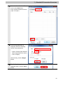
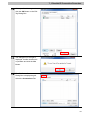
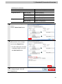
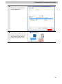
No.FST-ZTH130088A
CJ Series
EtherNet/IPTM Connection Guide
OMRON Corporation
Vision System
FZ5 Series
P588-E1-01
About Intellectual Property Rights and Trademarks
Microsoft product screen shots reprinted with permission from Microsoft Corporation.
Windows is a registered trademark of Microsoft Corporation in the USA and other countries.
ODVA and EtherNet/IPTM are trademarks of ODVA.
Company names and product names in this document are the trademarks or registered
trademarks of their respective companies.
Table of Contents
1.
Related Manuals .......................................................................................... 1
2.
Terms and Definitions................................................................................. 2
3.
Precautions .................................................................................................. 3
4.
Overview ...................................................................................................... 4
5.
Applicable Devices and Device Configuration ........................................ 5
6.
7.
8.
9.
5.1.
Applicable Devices .............................................................................. 5
5.2.
Device Configuration ........................................................................... 6
EtherNet/IP Settings.................................................................................... 7
6.1.
EtherNet/IP Communications Parameters .......................................... 7
6.2.
Allocating the Tag Data Links .............................................................. 7
EtherNet/IP Connection Procedure ......................................................... 10
7.1.
Work Flow .......................................................................................... 10
7.2.
Setting Up the FZ5 Sensor Controller ................................................ 11
7.3.
Setting Up the PLC ............................................................................ 16
7.4.
Setting Up the Network...................................................................... 26
7.5.
Checking the EtherNet/IP Communications ...................................... 38
Initialization Method.................................................................................. 43
8.1.
Initializing the PLC ............................................................................. 43
8.2.
Initializing the FZ5 Sensor Controller ................................................ 44
Revision History ........................................................................................ 45
1.Related Manuals
1. Related Manuals
The table below lists the manuals related to this document.
To ensure system safety, make sure to always read and heed the information provided in all
Safety Precautions, Precautions for Safe Use, and Precaution for Correct Use of manuals for
each device which is used in the system.
Cat. No.
W472
Model
CJ2H-CPU6[]-EIP
Manual name
CJ-series CJ2 CPU Unit Hardware User's Manual
CJ2H-CPU6[]
CJ2M-CPU[][]
W473
CJ2H-CPU6[]-EIP
CJ-series CJ2 CPU Unit Software User's Manual
CJ2H-CPU6[]
CJ2M-CPU[][]
W465
CJ1W-EIP21
EtherNet/IPTM Unit Operation Manual
CJ2H-CPU6[]-EIP
W446
CJ2M-CPU3[]
-
CX-Programmer Operation Manual
Image Processing System Instruction Sheet
9910002-2
FZ5-60[]/60[]-10
FZ5-110[]/110[]-10
FZ5-L35[]/L35[]-10
Z340
FZ5-L35[]
Vision Sensor FH/FZ5 Series Vision System
FZ5-6[][]/11[][]
User's Manual
FZ5-L35[]
Vision Sensor FH/FZ5 Series Vision System
FZ5-6[][]/11[][]
Processing Item Function Reference Manual
FZ5-L35[]
Vision Sensor FH/FZ5 Series Vision System
FZ5-6[][]/11[][]
User's Manual (Communications Settings)
9524422-4
Z341
Z342
Image Processing System Instruction Sheet
1
2.Terms and Definitions
2. Terms and Definitions
Term
Node
Explanation and Definition
Controllers and devices are connected to the EtherNet/IP network via the
EtherNet/IP ports. The EtherNet/IP recognizes each EtherNet/IP port
connected to the network as one node.
When a device with two EtherNet/IP ports is connected to the
EtherNet/IP network, the EtherNet/IP recognizes this device as two
nodes.
The EtherNet/IP achieves the communications between controllers or the
communications between controllers and devices by exchanging data
between these nodes connected to the network.
Tag
A minimum unit of the data that is exchanged on the EtherNet/IP network
is called a tag. The tag is defined as a network variable or as a physical
address, and it is allocated to the memory area of each device.
Tag set
In the EtherNet/IP network, a data unit that consists of two or more tags
can be exchanged. The data unit consisting of two or more tags for the
data exchange is called a tag set. Up to eight tags can be configured per
tag set for OMRON controllers.
Tag data link
In the EtherNet/IP, the tag and tag set can be exchanged cyclically
between nodes without using the user program. This standard feature on
the EtherNet/IP is called a tag data link.
Connection
A connection is used to exchange data as a unit within which data
concurrency is maintained. The connection consists of tags or tag sets.
Creating the concurrent tag data link between the specified nodes is
called a "connection establishment ". When the connection is
established, the tags or tag sets that configure the connection are
exchanged between the specified nodes concurrently.
Originator and
To perform tag data links, one node requests the opening of a
Target
communications line called a "connection".
The node that requests opening the connection is called an "originator",
and the node that receives the request is called a "target".
Tag data link
The tag data link parameter is the setting data to perform the tag data
parameter
link. It includes the data to set tags, tag sets, and connections.
EDS file
A file that describes the number of I/O points for the EtherNet/IP device
and the parameters that can be set via EtherNet/IP.
2
3.Precautions
3. Precautions
(1) Understand the specifications of devices which are used in the system. Allow some
margin for ratings and performance. Provide safety measures, such as installing safety
circuit in order to ensure safety and minimize risks of abnormal occurrence.
(2) To ensure system safety, always read and heed the information provided in all Safety
Precautions, Precautions for Safe Use, and Precaution for Correct Use of manuals for
each device used in the system.
(3) The user is encouraged to confirm the standards and regulations that the system must
conform to.
(4) It is prohibited to copy, to reproduce, and to distribute a part or the whole of this
document without the permission of OMRON Corporation.
(5) The information contained in this document is current as of December 2013. It is subject
to change without notice for improvement.
The following notations are used in this document.
Indicates a potentially hazardous situation which, if not avoided,
may result in minor or moderate injury or property damage.
Precautions for Correct Use
Precautions on what to do and what not to do to ensure proper operation and performance.
Additional Information
Additional information to read as required.
This information is provided to increase understanding or make operation easier.
Symbol
The triangle symbol indicates precautions (including warnings).
The specific operation is shown in the triangle and explained in text.
This example indicates a general precaution.
3
4.Overview
4. Overview
This document describes the procedure for connecting the Vision System (FZ5 Sensor
Controller + Camera) (FZ5 series) of OMRON Corporation (hereinafter referred to as
OMRON) with CJ-series Programmable Controller + Ethernet/IP Unit (hereinafter referred to
as the PLC), and the procedure to check their connection.
Refer to Section 6 EtherNet/IP Settings and Section 7 EtherNet/IP Connection Procedure to
understand the setting method and key points to operate the tag data link for EtherNet/IP.
In this document, CJ-series EtherNet/IP Unit and the built-in EtherNet/IP port of CJ-series CJ2
CPU Unit are collectively called as the "EtherNet/IP Unit".
4
5.Applicable Devices and Device Configuration
5. Applicable Devices and Device Configuration
5.1. Applicable Devices
The applicable devices are as follows:
Manufac
Name
Model
turer
OMRON
CJ2 CPU Unit
CJ2[]-CPU[][]
OMRON
EtherNet/IP Unit
CJ1W-EIP21
CJ2H-CPU6[]-EIP
CJ2M-CPU3[]
OMRON
FZ5 Sensor Controller
LCD-integrated Controller FZ5-60[]/60[]-10
FZ5-110[]/110[]-10
OMRON
Box-type Controller FZ5-L35[]/L35[]-10
0.3 Megapixel Digital Camera
FZ-SC/S
0.3 Megapixel Small Digital Camera
FZ-SFC/SF
0.3 Megapixel Small Digital Pen-Shaped Camera
FZ-SPC/SP
0.3 Megapixel High-Speed Camera
FZ-SHC/SH
2 Megapixel Digital Camera
FZ-SC2M/S2M
5 Megapixel Digital Camera
FZ-SC5M2/S5M2
Intelligent Camera
FZ-SLC100
Intelligent Compact Camera
FZ-SQ010F/SQ050F
FZ-SQ100F/SQ100N
Precautions for Correct Use
As applicable devices above, the devices with the models and versions listed in Section 5.2.
are actually used in this document to describe the procedure for connecting devices and
checking the connection.
You cannot use devices with versions lower than the versions listed in Section 5.2.
To use the above devices with versions not listed in Section 5.2 or versions higher than those
listed in Section 5.2, check the differences in the specifications by referring to the manuals
before operating the devices.
Additional Information
This document describes the procedure to establish the network connection. Except for the
connection procedure, it does not provide information on operation, installation or wiring
method. It also does not describe the functionality or operation of the devices. Refer to the
manuals or contact your OMRON representative.
5
5.Applicable Devices and Device Configuration
5.2. Device Configuration
The hardware components to reproduce the connection procedure of this document are as
follows:
Personal computer
(CX-One, installed,
OS: Windows 7 )
FZ5-L350
CJ2M-CPU32
(Built-in EtherNet/IP port)
LAN
cable
USB cable
Switching hub
W4S1-05C
Manufacturer
OMRON
OMRON
OMRON
OMRON
OMRON
OMRON
-
OMRON
OMRON
OMRON
OMRON
-
Name
CPU Unit
(Built-in EtherNet/IP port)
Power Supply Unit
Switching hub
CX-One
CX-Programmer
Network-Configurator
Personal computer
(OS: Windows 7)
USB cable
(USB 2.0 type B connector)
LAN cable (STP (shielded,
twisted-pair) cable of Ethernet
category 5 or higher)
FZ5 Sensor Controller
Camera
Camera cable
Monitor (analog RGB monitor)
USB connected mouse
USB connected mouse
FZ-M08
FZ-VS
Model
CJ2M-CPU32
CJ1W-PA202
W4S1-05C
CXONE-AL[][]C-V4
/ AL[][]D-V4
(Included in CX-One)
(Included in CX-One)
-
FZ-SC2M
Version
Ver.2.0
(Ver.2.12)
Ver.1.00
Ver.4.[][]
Ver.9.50
Ver.3.56
-
FZ5-L350
FZ-SC2M
FZ-VS
FZ-M08
-
Ver.5.12
Precautions for Correct Use
Update the CX-Programmer and Network Configurator to the versions specified in this
section or higher versions using the auto update function.
If a version not specified in this section is used, the procedures described in Section 7 and
subsequent sections may not be applicable. In that case, use the equivalent procedures
described in the CX-Programmer Operation Manual (Cat. No. W446) and Network
Configurator Online Help.
Additional Information
The system configuration in this document uses USB for the connection between the
personal computer and PLC. For information on how to install the USB driver, refer to A-5
Installing the USB Driver of the CJ-series CJ2 CPU Unit Hardware User's Manual (Cat. No.
W472).
6
6.EtherNet/IP Settings
6. EtherNet/IP Settings
This section describes the specifications such as communication parameters and tag data link
that are set in this document.
6.1. EtherNet/IP Communications Parameters
The communications parameter required connecting the PLC and the FZ5 Sensor Controller
via EtherNet/IP is given below.
PLC (EtherNet/IP Unit)
FZ5 Sensor Controller
(node 1)
(node 2)
Unit number
0
-
Node address
1
2
IP address
192.168.250.1
192.168.250.2
Subnet mask
255.255.255.0
255.255.255.0
6.2. Allocating the Tag Data Links
The tag data links are allocated for the FZ5 Sensor Controller as shown below.
Output area
D10000
(PLC to
Input area
D10100
FZ5 Sensor Controller)
D10009
20 bytes
(FZ5 Sensor Controller to
PLC)
D10123
48 bytes
Additional Information
For details on the control output, command codes, and response codes, refer to Memory
Allocation in Section 2 Methods for Connecting and Communicating with External Devices Communicating with EtherNet/IP of the Vision Sensor FH/FZ5 Series Vision System User's
Manual (Communications Settings) (Cat. No. Z342).
7
6.EtherNet/IP Settings
■ Details on output area
Bit
15
14 13 12 11 10
D10100 ERCLR
9
8
7
6
5
4
3
2
XEXE
D10103
0 Meaning
STEP EXE Control output
DSA (2 words)
D10101
D10102
1
CMD-CODE
Command code
(2 words)
D10104
D10105
D10106
D10107
Command
CMD-PARAM
parameter
(6 words max)
D10108
D10109
EXE: Command Request Bit: Turned ON to execute a command.
STEP: Measure Bit: Turned ON to execute a measurement.
XEXE: Flow Command Request Bit: Turned ON to request execution of a command during
execution of fieldbus flow control.
ERCLR: Error Clear Bit: Turned ON to clear the Error Status bit.
DSA: Data Output Request Bit: Turned ON to request data output.
8
6.EtherNet/IP Settings
■ Details on input area
Bit
15 14 13 12 11
D10100 ERR
10
9
8
XWAIT XBUSY XFLG
7
6
5
4
3
RUN OR
2
1
BUSY FLG Control output
GATE (2 words)
D10101
D10102
D10103
D10104
D10105
D10106
D10107
D10108
D10109
D10110
D10111
D10112
D10113
D10114
D10115
D10116
D10117
D10118
D10119
D10120
D10121
D10122
D10123
0 Meaning
CMD-CODE
RES-CODE
RES-DATA
Command code
(2 words)
Response code
(2 words)
Response data
(2 words)
DATA0
Output data 0
DATA1
Output data 1
DATA2
Output data 2
DATA3
Output data 3
DATA4
Output data 4
DATA5
Output data 5
DATA6
Output data 6
DATA7
Output data 7
FLG: Command Completion Bit: Turned ON when command execution is completed.
BUSY: Command Busy Bit: Turned ON when command execution is in progress.
OR: Overall Judgement Bit: Turned ON when the overall judgement is NG.
RUN: Run Mode Bit: Turned ON while the Sensor Controller is in Run Mode.
XFLG: Flow Command Completion Bit: Turned ON when execution of a command that was
input during the execution of fieldbus flow control has been completed (i.e., when
XBUSY turns OFF).
XBUSY: Flow Command Busy Bit: Turned ON when execution of a command that was
input during execution of fieldbus flow control is in progress.
XWAIT: Flow Command Wait Bit: Turned ON when a command can be input during the
execution of fieldbus flow control.
ERR: Error Signal: Turned ON when the Sensor Controller detects an error signal.
GATE: Data Output Completion Bit: Turned ON when data output is completed.
9
7.EtherNet/IP Connection Procedure
7. EtherNet/IP Connection Procedure
This section describes the procedure for connecting the FZ5 Sensor Controller to the PLC via
EtherNet/IP.
This document explains the procedures for setting up the PLC and the FZ5 Sensor Controller
from the factory default setting. For the initialization, refer to Section 8 Initialization Method.
7.1. Work Flow
Take the following steps to operate the tag data link for EtherNet/IP.
7.2. Setting Up the FZ5 Sensor Controller
↓
7.2.1. Parameter Settings
↓
7.3. Setting Up the PLC
↓
7.3.1. Hardware Settings
↓
7.3.2. Starting the CX-Programmer and
Connecting Online with the PLC
↓
7.3.3. Creating the I/O Table and setting
IP Addresses
↓
7.4. Setting Up the Network
↓
7.4.1. Start the Network Configurator and
Uploading Configuration
↓
7.4.2. Setting Tags
↓
7.4.3. Setting the Connection
↓
7.4.4. Transferring the Tag Data Link
Parameters
↓
7.5. Checking the EtherNet/IP
Communications
↓
7.5.1 Checking the Connection Status
↓
7.5.2 Checking the Data that are Sent
and Received
Set up the FZ5 Sensor Controller.
Set the parameters for the FZ5 Sensor Controller.
Set up the PLC.
Set the hardware switches on the EtherNet/IP Unit
and wire the network.
Start the CX-Programmer and connect online with
the PLC.
Create the I/O table and set the IP address of the
PLC.
Set the tag data links for the EtherNet/IP.
Start the Network Configurator and upload the
network configuration.
Register the tags of the send area and receive area.
Associate the target device with the tags of the
originator.
Transfer the set tag data link parameters to the PLC.
Confirm that the EtherNet/IP tag data links are
operated normally.
Check the connection status of EtherNet/IP.
Confirm that the correct data are sent and received.
10
7.EtherNet/IP Connection Procedure
7.2. Setting Up the FZ5 Sensor Controller
Set up the FZ5 Sensor Controller.
7.2.1. Parameter Settings
Set the parameters for the FZ5 Sensor Controller.
1
Connect the Camera, Monitor,
USB connected mouse, and the
LAN cable to the FZ5 Sensor
Controller.
Connect the power supply cable
to the Power terminal.
2
Turn ON the power supply to the
3
The Language setting Dialog
FZ5 Sensor Controller.
Box is displayed on the Monitor
connected to the FZ5 Sensor
Controller only at the initial start.
Select English and click the OK
Button.
Confirm that your desired
Language is selected and click
the Yes Button.
4
Select System Settings from
the Tool Menu on the FZ-PanDA
Dialog Box that are shown on
the Monitor connected to the
FZ5 Sensor Controller.
11
7.EtherNet/IP Connection Procedure
5
Select System
Settings-Startup-Startup
setting from the tree.
The Language setting Dialog
Box is displayed. Select the
Communication Tab.
6
The Communication module
select Dialog Box is displayed.
Select EtherNet/IP from the
Fieldbus pull-down list.
Then, click the Apply Button.
Click the Close Button to close
the System Settings Dialog Box.
7
8
* The data set in the System
Settings Dialog Box as shown
on the right becomes enabled
after the settings are saved, and
then the FZ5 Sensor Controller
is restarted.
Select Data save from the
Function Menu.
The Data save Dialog Box is
displayed. Click the OK Button.
12
7.EtherNet/IP Connection Procedure
9
10
Select System restart from the
Function Menu.
The System restart Dialog Box
is displayed. Check the contents
and click the OK Button.
11
After restarting, select System
12
Select System Settings -
Settings from the Tool Menu.
Communication Ethernet(Normal(UDP)) from
the tree.
13
7.EtherNet/IP Connection Procedure
13
The dialog box on the right is
displayed. Select the Use the
following IP address Option for
Address setting and set the
following values.
IP address: 192.168.250.2
Subnet mask: 255.255.255.0
* To change a value, click the
* How to change values.
Button in the item in which a
value is to be set. The numeric
keyboard is displayed. Enter
values using the mouse. After
entering the values, click the
OK Button on the numeric
keyboard.
14
7.EtherNet/IP Connection Procedure
14
When a value is changed, the
Apply Button is displayed. Click
the Apply Button.
While the setting is being
processed, the dialog box on
the right is displayed.
After the dialog box disappears,
click the Close Button to close
the System Settings Dialog Box.
15
In the same way as steps 7 and
8, select Data save from the
Function Menu.
16
In the same way as steps 9 and
10, select System restart from
the Function Menu.
15
7.EtherNet/IP Connection Procedure
7.3. Setting Up the PLC
Set up the PLC.
7.3.1. Hardware Settings
Set the hardware switches on the EtherNet/IP Unit and wire the network.
Precautions for Correct Use
Make sure that the power supply is OFF when you perform the setting up.
1
Make sure that the power supply
to the PLC is OFF.
* If the power supply is turned
ON, settings may not be
applicable as described in the
following procedure.
2
Check the position of the
hardware switches on the front
of the EtherNet/IP Unit by
referring to the right figure.
3
Set the Unit number setting
switch to 0.
The unit number is used to identify individual CPU Bus Units when more than
one CPU Bus Unit is mounted to the same PLC. Use a small screwdriver to
make the setting, taking care not to damage the rotary switch. The unit
number is factory-set to 0.
16
7.EtherNet/IP Connection Procedure
4
Set the Node address setting
switches to the following default
settings.
[NODE No.x161]: 0
With the FINS communications service, when there are multiple EtherNet/IP
Units connected to the Ethernet network, the EtherNet/IP Units are identified
by node addresses. Use the node address switches to set the node address
between 01 and FE hexadecimal (1 to 254 decimal).Do not set a number that
has already been set for another node on the same network.
[NODE No.x160]: 1
* Set the IP address to
192.168.250.1.
The left switch sets the sixteens digit (most significant digit) and the right
switch sets the ones digit (least significant digit).The node address is
factory-set to 01.
Default IP address = 192.168.250.node address
With the factory-default node address setting of 01, the default IP address is
192.168.250.1.
* By default, the first to third
octets of the local IP address
are fixed to 192.168.250. The
fourth octet is the values that
were set with the Node
address setting switches.
5
Connect the LAN cable to the
CPU Unit
EtherNet/IP port of the PLC, and
Switching hub
PLC
connect the USB cable to the
USB port. Connect the Personal
computer, Switching hub and
PLC as shown in 5.2. Device
USB cable
LAN cable
Power Supply Unit
Configuration.
6
Turn ON the power supply to the
PLC.
The set IP address is displayed
on the seven-segment LED
indicators from right to left.
Afterwards, the rightmost 8 bits
of the IP address are displayed
in hexadecimal during normal
operation.
17
7.EtherNet/IP Connection Procedure
7.3.2. Starting the CX-Programmer and Connecting Online with the PLC
Start the CX-Programmer and connect online with the PLC.
Install the CX-One and USB driver in the Personal computer beforehand.
1
Start the CX-Programmer.
2
Select Auto Online - Direct
3
The Direct Online Dialog Box is
Online from the PLC Menu.
displayed. Select the USB
connection Option for
Connection Type and click the
Connect Button.
4
The dialog box on the right is
displayed. Check the contents
and click the No Button.
18
7.EtherNet/IP Connection Procedure
5
The dialog box on the right is
displayed, and the
CX-Programmer and the PLC
are automatically connected.
6
Confirm that the
CX-Programmer and the PLC
are normally connected online.
icon is pressed down
* The
during online connection.
Additional Information
If an online connection cannot be made to the PLC, check the cable connection.
Or, return to step 2, check the settings and repeat each step.
Refer to Connecting Directly to a CJ2 CPU Unit Using a USB Cable in Chapter 3
Communications in PART 3: CX-Server Runtime of the CX-Programmer Operation Manual
(Cat. No. W466) for details.
Additional Information
The dialog boxes explained in the following procedures may not be displayed depending on
the environmental setting of CX-Programmer.
For details on the environmental setting, refer to Options and Preferences in Chapter 3
Project Reference in PART 1: CX-Programmer of the CX-Programmer Operation Manual
(Cat. No. W446). This document explains the setting procedure when the Confirm all
operations affecting the PLC Check Box is selected.
19
7.EtherNet/IP Connection Procedure
7.3.3. Creating the I/O Table and setting IP Addresses
Create the I/O table and set the IP address of the PLC.
1
If the operating mode of the PLC
is RUN Mode or Monitor Mode,
change it to Program Mode by
following the steps below.
(1) Select Operating Mode Program from the PLC Menu
of the CX-Programmer.
(2) The dialog box on the right is
displayed. Confirm that there
is no problem and click the
Yes Button.
* Refer to Additional
Information on the previous
page for the settings
concerning the dialog display.
(3) Confirm that Stop/Program
Mode is displayed on the right
of the PLC model in the
project workspace of the
CX-Programmer.
2
Select Edit - I/O Table and Unit
Setup from the PLC Menu of the
CX-Programmer.
The PLC IO Table Window is
displayed.
20
7.EtherNet/IP Connection Procedure
3
Select Create from the Options
Menu of the PLC IO Table
Window.
The dialog box on the right is
displayed. Confirm that there is
no problem and click the Yes
Button.
The dialog box on the right is
displayed. Confirm that there is
no problem and click the Yes
Button.
21
7.EtherNet/IP Connection Procedure
4
The Transfer from PLC Dialog
Box is displayed. Select the I/O
Table Check Box and the SIO
Unit Parameters Check Box,
and click the Transfer Button.
When the transfer is completed,
the Transfer Results Dialog Box
is displayed.
Confirm that the transfer was
normally executed by referring
to the message in the dialog
box.
When the I/O table is created
normally, the dialog box displays
as follows:
Transfer Success: 1 Unit
Transfer Unsuccessful: 0 Unit.
Click the OK Button.
22
7.EtherNet/IP Connection Procedure
5
On the PLC IO Table Window,
click + to the left of Built-in
Port/Inner Board to display
CJ2M-EIP21.
* The right figure displays the
CPU Unit (built-in EtherNet/IP
port) specified in 5.2. Device
Configuration. When you use an
applicable EtherNet/IP Unit not
specified in 5.2. Device
Configuration, the display
position and name are different
from this figure.
Right-click CJ2M-EIP21 and
select Unit Setup.
6
The Edit Parameters Dialog Box
is displayed. Select the TCP/IP
Tab.
Make the following settings in
the IP Address Field.
・Select the Use the following
address Check Box
・IP Address: 192.168.250.1
・Subnet Mask: 255.255.255.0
Click the Transfer [PC to Unit]
Button.
23
7.EtherNet/IP Connection Procedure
7
The dialog box on the right is
displayed. Confirm that there is
no problem and click the Yes
Button.
Confirm that parameters were
normally transferred to the Unit,
and click the Close Button.
8
A dialog box on the right is
displayed. Check the contents
and click the Yes Button.
When the Unit is restarted, the
dialog box on the right is
displayed. Check the contents
and click the OK Button.
24
7.EtherNet/IP Connection Procedure
9
Click the Compare Button and
confirm that IP Address was
correctly changed.
10
After confirming that parameters
11
Click the OK Button on the Edit
match, click the Close Button.
Parameters Dialog Box.
25
7.EtherNet/IP Connection Procedure
7.4. Setting Up the Network
Set the tag data links for the EtherNet/IP.
7.4.1. Starting the Network Configurator and Uploading the Configuration
Start the Network Configurator and upload the network configuration.
Precautions for Correct Use
Confirm that the LAN cable is connected before taking the following procedure.
When it is not connected, turn OFF the power supply to each device and then connect the
LAN cable.
1
Right-click CJ2M-EIP21 on the
PLC IO Table Window, and
select Start Special
Application - Start with
Settings Inherited.
The Select Special Application
Dialog Box is displayed. Select
Network Configurator and click
the OK Button.
26
7.EtherNet/IP Connection Procedure
2
Network Configurator is started.
Hardware
List
Window
3
Network Configuration Pane
Select Select Interface - CJ2
USB/Serial Port from the
Option Menu.
4
Select Connect from the
5
The Setup Interface Dialog Box
Network Menu.
is displayed. Confirm that the
following settings are made.
・Port Type: USB
・Port: OMR0
・Baud Rate: 115200 Bit/s
Click the OK Button.
6
The Select Connect Network
Port Dialog Box is displayed.
Select Back Plane CJ2M-EIP21 - TCP:2, and click
the OK Button.
27
7.EtherNet/IP Connection Procedure
7
The Select Connected Network
Dialog Box is displayed. Click
the OK Button.
Additional Information
If an online connection cannot be made to the PLC, check the cable connection.
Or, return to step 1, check the settings and repeat each step.
For details, refer to 6-2-9 Connecting the Network Configurator to the Network in Section 6
Tag Data Link Functions of the EtherNet/IP Unit Operation Manual (Cat. No. W465).
8
9
When an online connection is
established normally, the color
of the icon on the figure changes
to blue.
Select Upload from the Network
Menu to upload the device
information on the network.
10
The dialog box on the right is
displayed. Confirm that there is
no problem and click the Yes
Button.
28
7.EtherNet/IP Connection Procedure
11
The Target Device Dialog Box is
displayed. Select the
192.168.250.1 Check Box and
the 192.168.250.2 Check Box.
Click the OK Button.
* If 192.168.250.1 and
192.168.250.2 are not displayed
on the dialog box, click the Add
Button to add the address.
* The displayed addresses
depend on the status of the
Network Configurator.
12
The device parameters are
uploaded. When uploading is
completed, the dialog box on the
right is displayed. Check the
contents and click the OK
Button.
13
After uploading is completed,
confirm that the IP address of
each node is updated on the
Network Configuration Pane as
follows:
IP address of node 1:
192.168.250.1
IP address of node 2
192.168.250.2
* The destination device icon
changes to the FZ Series
device.
29
7.EtherNet/IP Connection Procedure
7.4.2. Setting Tags
Register the tags of the send area and receive area.
This section explains the receive settings and send settings of the target device in order.
1
On the Network Configuration
Pane of the Network
Configurator, right-click the node
1 device and select Parameter Edit.
2
The Edit Device Parameters
Dialog Box is displayed. Select
the Tag Sets Tab.
3
The data on the Tag Sets Tab is
displayed. Select the
In-Consume Tab and click the
Edit Tags Button.
30
7.EtherNet/IP Connection Procedure
4
The Edit Tags Dialog Box is
displayed. Select the In Consume Tab and click the New
Button.
Here, register an area where
node 1 receives data from node
2.
5
The Edit Tag Dialog Box is
displayed. Enter the following
values in the parameters.
・Name: D10100 (Start address
of the input data to node 1)
・Size: 48 (Byte)
After entering, click the Regist
Button.
6
The Edit Tag Dialog Box is
displayed again. Click the Close
Button.
31
7.EtherNet/IP Connection Procedure
7
Select the Out - Produce Tab
and click the New Button.
Here, register the data sent from
node 1 to node 2.
8
The Edit Tag Dialog Box is
displayed. Enter the following
values in the parameters.
・Name: D10000 (Start address
of the output data from node 1)
・Size: 20 (Byte)
After entering, click the Regist
Button.
9
The Edit Tag Dialog Box is
displayed again. Click the Close
Button.
32
7.EtherNet/IP Connection Procedure
10
When you finish the registration,
click the OK Button on the Edit
Tag Dialog Box.
11
The dialog box on the right is
displayed. Confirm that there is
no problem and click the Yes
Button.
12
The Edit Device Parameters
Dialog Box is displayed again.
Select the Connections Tab.
33
7.EtherNet/IP Connection Procedure
7.4.3. Setting the Connection
Associate the tags of the target device (that receives the open request) with the tags of the
originator (that requests opening).
1
Select 192.168.250.2 in the
Unregister Device List Field.
Click the Down Arrow Button
that is shown in the dialog box.
2
192.168.250.2 is registered in
the Register Device List Field.
Select 192.168.250.2 and click
the New Button.
3
The Edit Connection Dialog Box
is displayed. Select Consume
Data From/Produce Data To
from the Connection I/O Type
pull-down list.
Set the values listed in the
following table to the Originator
Device Field and the Target
Device Field.
34
7.EtherNet/IP Connection Procedure
■ Settings of connection
Connection allocation
Connection I/O type
Originator device
Target device
4
Setting value
Consume Data From/Produce Data To
Input Tag Set
D10100-[48 Byte]
Connection Type
Multi-cast connection
Output Tag Set
D10000-[20 Byte]
Connection Type
Point to Point connection
Output Tag Set
Input_101-[48 Byte]
Input Tag Set
Output_100-[20 Byte]
Confirm that the settings are
correct.
Click the Show Detail Button.
5
Confirm that the Packet Interval
(RPI) is set to 4 ms or longer
and click the Regist Button.
* The same dialog box as step 4
is displayed again if you click
the Hide Detail Button.
6
The Edit Connection Dialog Box
is displayed again. Click the
Close Button.
35
7.EtherNet/IP Connection Procedure
7
The Edit Device Parameters
Dialog Box is displayed again.
Click the OK Button.
8
When the connection setting is
completed, the registered node
address is displayed under the
device icon of node 2 on the
Network Configuration Pane.
36
7.EtherNet/IP Connection Procedure
7.4.4. Transferring the Tag Data Link Parameters
Transfer the set tag data link parameters to the PLC.
1
Right-click the device icon of
node 1 on the Network
Configuration Pane and select
Parameter - Download.
2
The dialog box on the right is
displayed. Confirm that there is
no problem and click the Yes
Button.
3
The tag data link parameters are
downloaded from Network
Configurator to the PLC.
4
The dialog box on the right is
displayed. Check the contents
and click the OK Button.
37
7.EtherNet/IP Connection Procedure
7.5. Checking the EtherNet/IP Communications
Confirm that the EtherNet/IP tag data links are operated normally.
7.5.1. Checking the Connection Status
Check the connection status of EtherNet/IP.
1
Confirm that the tag data links are
normally in operation by checking
the LED indicators on each device.
・PLC (EtherNet/IP Unit)
The LED indicators in normal
status are as follows:
[MS]: Lit green
[NS]: Lit green
[COMM]: Lit yellow
(EtherNet/IP Unit)
[100M] or [10M]: Lit yellow
2
Confirm that the tag data links are
normally in operation by checking
the status information on the
Monitor Device Window of the
Network Configurator.
Right-click the device icon of node 1
on the Network Configuration Pane
and select Monitor.
38
7.EtherNet/IP Connection Procedure
3
The dialog box on the right displays
the Status 1 Tab Page of the Monitor
Device Dialog Box.
When the same items are selected
as shown on the right, the data links
are normally in operation.
Click the Close Button.
Number: Node number
Blue: Connection normal
4
Select Disconnect from the
Network Menu to go offline.
5
The color of the icon on the figure
6
Select Exit from the File Menu to
changes from blue.
exit the Network Configurator.
39
7.EtherNet/IP Connection Procedure
7.5.2. Checking the Data that are Sent and Received
Confirm that the correct data are sent and received.
Confirm safety sufficiently before monitoring power flow and present value
status in the Ladder Section window or before monitoring present values in the
Watch window.
If force-set/reset or set/reset operations are incorrectly performed by pressing
short-cut keys, the devices connected to Output Units may malfunction,
regardless of the operating mode of the CPU Unit.
1
Confirm that the PLC is in Program
Mode.
* If the PLC is not in Program Mode,
change to Program Mode by
referring to step 1 of 7.3.3. Setting
the IP Address.
2
Select Edit - Memory from the PLC
Menu.
40
7.EtherNet/IP Connection Procedure
3
Double-click D from the list in the
PLC Memory Window that is
displayed.
4
Select Display - Binary from the
View Menu.
5
Select Monitor from the Online
Menu.
6
The Monitor Memory Areas Dialog
Box is displayed. Confirm that the D
Check Box is selected and click the
Monitor Button.
7
Enter 10000 in the Start Address
Field in the D Window.
Confirm that the start address was
changed to D10000.
41
7.EtherNet/IP Connection Procedure
8
9
Select bits 12 and 4 of D10002 and
bit 4 of D10003, and then click the
On Button. (After turning them ON,
the values change to 1.)
Then, turn ON bit 0 of D10000.
* D10002 and D10003 are an area
for a command code and contain
00101010(Hex) (Measurement
command).
Bit 0 of D10000 is a command
execution (EXE) flag.
After the measurement is
completed, OK is displayed on the
dialog box.
10
Enter 10100 in the Start Address
Field in the D Window.
Confirm that the start address was
changed to D10100.
11
Confirm that values of DM10102 to
DM10105 are set as shown on the
right.
D10102 and D10103 contain the
command code that you set.
D10104 and D10105 contain the
command execution result (0: OK).
42
8.Initialization Method
8. Initialization Method
This document explains the setting procedure from the factory default setting.
Some settings may not be applicable as described in this document unless you use the
devices with the factory default setting.
8.1. Initializing the PLC
To initialize the settings of the PLC, it is necessary to initialize the CPU Unit and EtherNet/IP
Unit. Change the PLC to PROGRAM mode before the initialization.
8.1.1. EtherNet/IP Unit
(1) Select Edit - I/O Table and Unit Setup from the PLC Menu of the CX-Programmer.
Right-click the EtherNet/IP Unit on the PLC IO Table Window and select Unit Setup from the
menu.
(2) Click the Restart Button on the Edit Parameters Dialog Box.
(3) A confirmation dialog box on the right is displayed. Confirm that there is no problem and
43
8.Initialization Method
click the Yes Button. On the Restart Unit Dialog Box, select the Return to out-of-box
configuration, and then emulate cycling power Option, and click the OK Button. A complete
dialog box is displayed. Check the contents and click the OK Button.
8.1.2. CPU Unit
To initialize the settings of the CPU Unit, select Clear All Memory Areas from the PLC
Menu of the CX-Programmer. On the Confirm All Memory Area Clear Dialog Box, select
the Initialize Option and click the OK Button.
8.2. Initializing the FZ5 Sensor Controller
For how to initialize the FZ5 Sensor Controller, refer to Initializing the Controller in Section 1
Before Operation of the Vision Sensor FH/FZ5 Series Vision System User's Manual
(Cat.No.Z340).
44
9.Revision History
9. Revision History
Revision
Date of revision
Revision reason and revision page
code
01
Dec. 20, 2013
First edition
45
46
2013
P588-E1-01
1213(-)