1
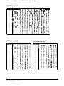
User’s Guide Update
Please update your User’s Guide with the following information.
These page-length settings have been added to your printer:
5.5, 7, 17, 14, 8, 6, 4, 3.5, and 3 inches.
See “Default-Setting Mode” in Chapter 3 for the groups of
available printer features. The page length feature has been
deleted from Group 1 and now appears in a new group
(Group 1 Extension). See the following table for a complete
list of Group 1 Extension settings.
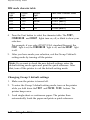
Group 1 Extension
Page length
Settings
11, 12, 8.5, 70/6(A4), 5.5, 7, 17, 14, 8, 6, 4,
3.5, and 3 inches
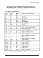
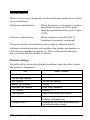
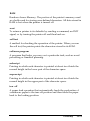
Changing Group 1 Extension default settings
1.
Make sure the printer is turned off.
2.
To enter the Group 1 Extension default-setting mode, turn
on the printer while you hold down the FONT and
PAPER FEED buttons. The printer beeps once.
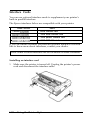
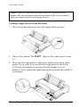
3.
Load single-sheet or continuous paper. The printer then
automatically loads the paper and prints a quick
reference.
Copyright © 1995 by Seiko Epson Corporation.
4004313
CO1 -00
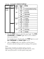
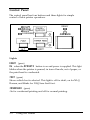
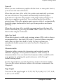
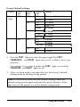
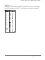
Group
Exter
Feature
FONT
light
Page
length
OFF
ON
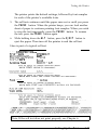
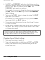
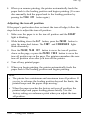
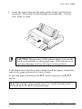
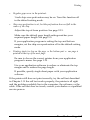
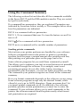
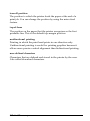
4.
Press the FONT button to select the page length. The FONT,
CONDENSED, and READY lights turn on, off, or blink to
show your selection.
For example, if you select 8 inches, the FONT light is on and
the CONDENSED and READY lights are off.
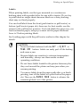
5.
After you have made your selection, exit the Group 1
Extension default-setting mode by turning off the printer.
Note:
If you want to check the new default settings, enter the
default-setting mode again and print the quick reference. After
that, turn off the printer to exit the default-setting mode.
FCC Compliance Statement
For United States Users
This equipment has been tested and found to comply with the limits for a Class B
digital device, pursuant to Part 15 of the FCC Rules. These limits are designed to
provide reasonable protection against harmful interference in a residential
installation. This equipment generates, uses and can radiate radio frequency energy
and, if not installed and used in accordance with the instructions, may cause
harmful interference to radio or television reception. However, there is no
guarantee that interference will not occur in a particular installation. If this
equipment does cause interference to radio and television reception, which can be
determined by turning the equipment off and on, the user is encouraged to try to
correct the interference by one or more of the following measures.
.
.
.
Reorient or relocate the receiving antenna.
Increase the separation between the equipment and receiver.
Connect the equipment into an outlet on a circuit different from that to which
the receiver is connected.
.
Consult the dealer or an experienced radio/TV technician for help.
WARNING
The connection of a non-shielded equipment interface cable to this equipment will
invalidate the FCC Certification of this device and may cause interference levels
which exceed the limits established by the FCC for this equipment. It is the
responsibility of the user to obtain and use a shielded equipment interface cable
with this device. If this equipment has more than one interface connector, do not
leave cables connected to unused interfaces. Changes or modifications not expressly
approved by the manufacturer could void the user’s authority to operate the
equipment.
For Canadian Users
This digital apparatus does not exceed the Class B limits for radio noise emissions
from digital apparatus as set out in the radio interference regulations of the
Canadian Department of Communications.
Le present appareil numerique n’emet pas de bruits radioelectriques depassant les
limites applicables aux appareils numeriques de Classe B prescrites dans le
reglement sur le brouillage radioelectrique edict6 par le Minis&e des
Communications du Canada.
Important Safety Instructions
.
Read all of these instructions before you set up your printer.
.
Follow all warnings and instructions marked on the printer.
.
Unplug the printer from the wall outlet before you clean it, and
use a damp cloth for cleaning, not liquid or aerosol cleaners.
.
Do not use your printer near water or spill any liquid on it.
.
Do not place the printer on an unstable cart, stand, table or other
surface that may allow the printer to fall.
.
Do not block any slots or openings in the cabinet. These are
provided for the ventilation necessary to ensure reliable
operation and protection from overheating. Placing the printer
on a bed, sofa, rug, or other similar surface may block the
openings. Also, do not place the printer in a built-in installation
unless proper ventilation is provided.
.
Never place the printer near or over a radiator or heat register.
.
Use the type of power source indicated on the label. If you are
not sure of the type of power available, consult your dealer or
local power company.
.
This printer may be equipped with a plug having a third
(grounding) pin, which fits only into a grounding-type outlet.
This is a safety feature. If you are unable to insert the plug into
the outlet, have an electrician replace your obsolete outlet. Do
not defeat the purpose of the grounding-type plug.
l
Do not put your printer where the cord will be walked on.
l
l
l
l
If you use an extension cord, make sure that the total of the
ampere ratings on the products plugged into the extension cord
does not exceed the extension cord’s ampere rating. Also, make
sure that the total of all products plugged into the wall outlet
does not exceed 15 amperes.
Never push objects of any kind into your printer because they
may touch dangerous voltage points or short out parts that
could result in a risk of fire or electric shock.
Except as specifically explained in the user’s manual, do not
attempt to repair the printer yourself. This could expose you to
dangerous voltage points or other risks. Refer all servicing in
those compartments to service personnel.
Unplug the printer from the wall outlet and have it repaired by a
qualified service person under the following conditions:
When the power cord or plug is damaged or frayed
If liquid has been spilled into it
If it has been exposed to rain or water
If it does not operate normally when the operating
instructions are followed. Adjust only those controls that are
covered by the operating instructions since improper
adjustment of other controls may result in damage and will
often require extensive work by a qualified technician to
restore the printer to normal operation.
If it has been dropped or the cabinet has been damaged
If it exhibits a distinct change in performance, indicating a
need for service.
Where United States Users Can Get Help
Epson America provides local customer support and service
through a nationwide network of authorized Epson dealers and
Service Centers.
Epson also provides the following support services through the
Epson Consumer Resource Center at (800) 922-8911:
Assistance in locating your nearest Authorized Epson Reseller or
Service Center
Technical assistance with the installation, configuration, and
operation of Epson products
Epson technical information library fax service
Product literature with technical specifications on our current
and new products
Sales of ribbons, supplies, parts, documentation, and accessories
for your Epson product
Customer Relations.
For United Kingdom Users
Epson product guarantee
Under the law, goods sold must comply with their description and
must be of merchantable quality and fit for their purpose or
correspond with any sample.
This guarantee does not affect the seller’s legal obligation or the
rights of the consumer in the “consumer transactions” under any
Statute, including Sections 12 to 15 of the Sales of Goods Act, 1979.
All Epson Products, other than OEM products, are fully guaranteed
against faulty operation or performance for a period of ONE YEAR
from date of purchase by the user of the product.
All claims under this guarantee MUST be supported by evidence of
purchase, normally the bill of sale invoice, and it is the responsibility
of the claimant to furnish such proof. Epson (UK) Limited does not
issue or operate any form of guarantee registration card.
Claims are made by the user returning the product to the supplier
from whom it was purchased or, if this is impractical, to any Epson
supplier who also handles the same product. In the event of any
difficulty, users are requested to contact the Service Co-ordinator
Manager at Epson (UK) Limited.
Epson (UK) Limited, or Epson Appointed Distributors, will at their
discretion repair or replace part or all of the product to provide, in
their judgement, a satisfactory performance of the product
consistent with its age and apparent usage.
This guarantee covers the cost of both the parts and labour required
to correct any malfunction of the equipment, but specifically
excludes: wear and tear, consumables, physical damage due to
incorrect use or misuse and damage or faulty operation due to
unauthorized and inexpert repair,
The guarantee is restricted to the performance of the product alone,
and Epson (UK) Limited does not accept responsibility for any
consequential loss or damage, nor claimed or implied performance,
when the product is used in any combination with other equipment
or program software.
Product guarantee may be invalidated as a result of excessive or
inappropriate use, use in adverse environment or in conditions
outside the specifications or if the product has been subjected to
unapproved modifications.
The guarantee does not cover visits to the user’s premises or the
repair or commissioning of the product on site.
Use of options
Epson (UK) Limited shall not be liable against any damages or
problems arising from the use of any options or consumable
products other than those designated as Original Epson Products or
Epson Approved Products by Epson (UK) Limited.
Safety information
Warning: This appliance must be earthed. Refer to rating plate for
voltage and check that the appliance voltage corresponds to the
supply voltage.
Important: The wires in the mains lead fitted to this appliance are
coloured in accordance with the following code:
Green and yellow - Earth
Blue - Neutral
Brown - Live
As the colours of the wires in the mains lead of this appliance may
not correspond with the coloured markings identifying the
terminals in your plug, proceed as follows:
The green and yellow wire must be connected to the terminal in the
plug which is marked with the letter E or with the earth symbol (&)
or coloured green or green and yellow.
The blue wire must be connected to the terminal in the plug marked
with the letter N or coloured black.
The brown wire must be connected to the terminal in the plug
marked with the letter L or coloured red.
If damage occurs to the plug, replace the cord set or consult a
qualified electrician.
Replace fuses only with a fuse of the correct size and rating.
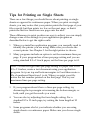
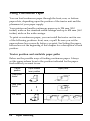
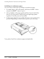
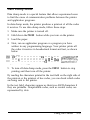
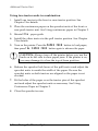
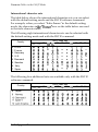
Tips for Printing on Single Sheets
There are a few things you should know about printing on single
sheets as opposed to continuous paper. When you print on single
sheets, you may notice that your printer prints the first page of your
file correctly but then prints too low on the next page, or that it
prints the last few lines from one page onto the next.
These differences in print position are easy to adjust; you can simply
change some of the settings in your application program as
described below to get the right results.
1. When you install an application program, you normally need to
identify the printer you are using. Make sure you choose the
correct printer. See Chapter 1 for the right printer to choose.
2. Many programs include an option to set the maximum lines per
page. If your program has a lines-per-page setting and you are
using standard 8.5 x 11-inch paper, set the lines per page to 61.
Note: To find the right lines-per-page setting for paper that is not
8.5 x 11 inches, create a test document using your application
program. Set your top and bottom margins to 0 and then create a
file of numbered lines from 1 to 66. When you print your file,
notice the last number printed on the first page. This is your
maximum lines-per-page setting.
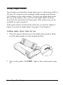
3.
If your program doesn’t have a lines-per-page setting, try
decreasing the top margin or increasing the bottom margin, or
both, until you get the results you want.
4.
You can also try adjusting the form length setting. For a
standard 8.5 x 11-inch page, try setting the form length at 10
inches.
5.
Some programs also let you indicate whether you are using
single sheets or continuous paper. Make sure you choose single
sheets.
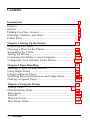
Contents
Introduction
Features .............................................................................................
Options ..............................................................................................
Finding Your Way Around ............................................................
Warnings, Cautions, and Notes ....................................................
Printer Parts ......................................................................................
1
2
4
4
5
Chapter 1 Setting Up the Printer
Unpacking the Printer ................................................................
Choosing a Place for the Printer ................................................
Assembling the Printer ..............................................................
Testing the Printer ......................................................................
Connecting the Printer to Your Computer .............................
Configuring Your Software for the Printer.. ..........................
1-1
Chapter 2 Paper Handling
Selecting a Paper Feeding Method ..........................................
Using Single Sheets ....................................................................
Using Continuous Paper ...........................................................
Switching Between Continuous and Single Sheets ..............
Printing on Special Paper ..........................................................
2-1
2-2
2-4
2-6
2-20
2-23
1-2
1-6
1-10
1-14
1-15
3-1
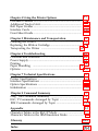
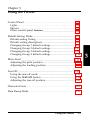
Chapter 3 Using the Printer
3-2
Control Panel ...............................................................................
Default-Setting Mode ................................................................. 3-5
Micro Feed ................................................................................... 3-15
Tear Off ........................................................................................ 3-18
Character Fonts ........................................................................... 3-21
Data Dump Mode ....................................................................... 3-23
X
Contents
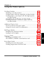
Chapter 4 Using the Printer Options
Cut-Sheet Feeders ......................................................................
Additional Tractor Unit .............................................................
Roll Paper Holder .......................................................................
Interface Cards ...........................................................................
Front Sheet Guide .......................................................................
4-1
4-2
4-13
4-16
4-22
4-25
5-1
Chapter 5 Maintenance and Transportation
Cleaning the Printer ................................................................... 5-2
Replacing the Ribbon Cartridge ............................................. 5 - 4
Transporting the Printer ............................................................ 5-4
Chapter 6 Troubleshooting
Problems and Solutions .............................................................
Power Supply ..............................................................................
Printing
Paper Handling ................................................................... 6-8
Options .........................................................................................
6-1
6-2
6-3
6-4
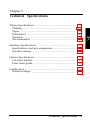
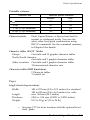
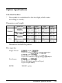
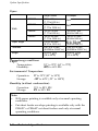
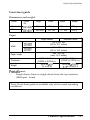
Chapter 7 Technical Specifications
Printer Specifications .................................................................
Interface Specifications ..............................................................
Option Specifications .................................................................
Initialization ................................................................................
7-1
7-2
7-11
7-15
7-18
Chapter 8 Command Summary
Using the Command Summary .............................................
ESC / P Commands Arranged by Topic .................................
IBM Commands Arranged by Topic ......................................
8-1
8-2
8-3
8-14
6-11
A-1
Appendix
Character Tables in the ESC/P Mode ...................................... A-2
Character Tables in the IBM Emulation Mode ....................... A-9
Glossary
Index
GL-1
Introduction
Your new Epson® 9-pin dot matrix printer combines a compact
design and high performance with a wide range of features.
Features
These features give your Epson printer outstanding value:
Fast printing speed. Prints up to 380 characters per second.
Easy paper handling. Provides four paper paths to suit your
printing needs: top, rear, bottom, and front loading.
Flexibility. You can load single sheets from the top paper slot
without removing your continuous paper supply.
Automatic paper loading. Loads single sheets and continuous
paper automatically.
Compatibility. Supports the Epson ESC/P® commands widely
used in application programs written for other Epson FX
printers.
An IBM@ emulation mode. Provides compatibility with many
application programs written for popular IBM@ printers.
Font selection. You can choose two draft and two Near Letter
Quality fonts (Epson Roman and Epson Sans Serif) directly from
the control panel as well as normal or condensed printing.
Default settings. You can customize the printer’s default settings
with the control panel buttons.
Thickness adjustment. You can set a simple lever to print on a
variety of paper types, including labels, envelopes, and multipart forms.
Options
You may choose a cut-sheet feeder, an additional tractor unit, a roll
paper holder, or a front sheet guide to enhance the use of your
printer. For additional information on these options, see Chapter 4.
Single-Bin Cut-Sheet Feeder
(C80637* for the standard-width carriage, C80639* for the wide
carriage)
This economical cut-sheet feeder automatically feeds up to 50
sheets of paper into your printer without reloading. You can also
manually load single sheets without removing the cut-sheet
feeder.
High-Capacity Cut-Sheet Feeder
(C80638* for the standard-width carriage, C80640* for the wide
carriage)
This cut-sheet feeder automatically feeds up to 150 sheets of
paper or 25 plain bond envelopes without reloading. You can
also create a double-bin cut-sheet feeder by connecting this cutsheet feeder to the single-bin model.
Additional Tractor Unit
(C80020* for the standard-width carriage, C80021* for the wide
carriage)
This option improves continuous-paper handling. It is especially
useful with continuous multi-part forms. You can also use it to
load two types of continuous paper in the printer at the same
time.
Roll Paper Holder
(#8310)
Available only for the standard-width carriage, the optional roll
paper holder makes it possible to use the many types of 8.5-inch
wide roll paper sold for telexes and similar machines.
Interface Card
Optional interface cards are available to supplement the printer’s
built-in parallel interface. Guidelines for choosing the right
interface and instructions on installing the cards are given in
Chapter 4.
Front Sheet Guide
(C814001 for the standard-width carriage, C814011 for the wide
carriage)
This front sheet guide allows you to load single sheets from the
front paper slot. (This option may not be available in some
countries.)
Front Paper Guide
(C814021 for the standard-width carriage, C814031 for the wide
carriage)
This front paper guide allows you to load single sheets from the
front paper slot. (This option is available in North and South
American countries only.)
The last figure in option part numbers, represented by an asterisk
(*), varies by country. Contact your local Epson dealer for the part
number in your country.
Finding Your Way Around
This manual provides fully illustrated, step-by-step instructions for
setting up and operating your printer.
Chapter 1 contains information on unpacking, setting up, testing,
and connecting the printer. Be sure to read this chapter first.
Chapters 2 and 3 include important information on paper
handling and day-to-day operation of your printer.
Chapter 6 contains troubleshooting information. If the printer
does not operate properly or the printed results are not what you
expect, see Chapter 6 for a list of problems and solutions.
Other chapters contain information on installing options, general
maintenance, specifications, and printer commands. There is also
a glossary of printer terms and an index.
Warnings, Cautions, and Notes
I!!!!!!’
t01
l
WARNINGS must be followed to avoid bodily injury.
CAUTIONS must be observed to avoid damage to your
equipment.
Notes contain important information and useful tips on the
operation of your printer.
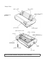
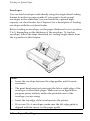
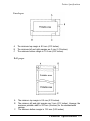
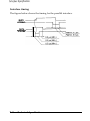
Printer Parts
paper guide
edge guides
lever
prilzfel cover
control panel
paper-fension unit
tractor
\\
ribbon cartridge
lever
parallel interfa
A\C inlet
Note: In some countries, the power cord is attached.
Chapter 1
Setting Up the Printer
Unpacking the Printer ............................................................... 1-2
Checking the parts ................................................................. 1-2
Removing the protective materials .................................... 1 - 3
Choosing a Place for the Printer . . . . . . . . . . . . . . . . . . . . . . . . . . . . . . . . . . . . 1-4
Assembling the Printer .............................................................. 1-6
Installing the ribbon cartridge.. ............................................ 1-6
Attaching the paper guide .................................................... 1-9
Testing the Printer ...................................................................... 1-10
Plugging in the printer .......................................................... 1-10
Running the self test .............................................................. 1-11
Connecting the Printer to Your Computer . . . . . . . . . . . . . . . . . . . . . . . . . . . . . 1-14
Configuring Your Software for the Printer ............................ 1-15
Choosing from a menu.. ........................................................ 1-15
Setting Up the Printer
l-l
Unpacking the Printer
This chapter contains information on unpacking, setting up, testing,
and connecting the printer. Read this chapter first.
Checking the parts
When you unpack the printer, make sure that you have all the parts
shown below and that none is damaged.
Printer
Power cord
Note: In some countries, the power cord is attached to the printer.
Store the packing materials in case you ever need to transport your
printer.
t
l
1-2
CAUTION: It is not possible to change the voltage of the
printer. If the label on the back of the printer does not
show the correct voltage for your country, contact your
dealer.
Setting Up the Printer
Unpacking the Printer
Removing the protective materials
To prevent damage during shipping, several pieces of protective
material are packed with your printer. You must remove these
before you put your printer together.
Follow the directions on the Notice Sheet inserted in your printer
when removing the protective material.
Note:
Make sure you remove all packing and protective materials
l
from your printer before turning on the power.
l
Store all packing and protective materials in case you ever
need to transport the printer.
Setting Up the Printer
1-3
Choosing a Place for the Printer
When selecting a place to set up your printer, keep the following in
mind:
Place the printer on a flat, stable surface.
l
Place the printer close enough to the computer for the printer
cable to reach.
l
Leave adequate room around the printer for easy operation,
maintenance, and proper ventilation.
l
0
t
l
CAUTION: Avoid locations that are subject to direct
sunlight, excessive heat, moisture, or dust.
Use a grounded outlet; do not use an adapter plug.
Place the printer where you can easily unplug the power cord.
Avoid electrical outlets controlled by wall switches or automatic
timers. Accidental disruption of power can erase information in
the memory of your printer.
Avoid outlets on the same circuit with large motors or other
appliances that might cause fluctuations in line voltage.
Keep the entire computer system away from potential causes of
electromagnetic interference such as loudspeakers or the base
units of cordless telephones.
1-4
Setting Up the Printer
Choosing a Place for the Printer
Note: If you plan to use a printer stand, follow these guidelines:
l
l
l
l
l
Use a stand that supports at least twice the weight of the
printer.
13.6 kg (30 Ibs) for the standard-width carriage
18.4 kg (40 Ibs) for the wide carriage
Never use a stand that tilts the printer at an angle of more
than 15 degrees from horizontal. If you install a cut-sheet
feeder, keep your printer absolutely level.
Make sure you provide enough clearance below the stand and
between its legs so that your continuous paper feeds
smoothly.
Position your printer’s power cord and interface cable so that
they do not interfere with paper feeding. If possible, secure
the cables to the printer stand.
Align the stack of paper so that the paper has a straight path
into the printer.
Setting UP the Printer
1-5
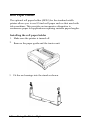
Assembling the Printer
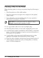
Installing the ribbon cartridge
1. Make sure the printer is not plugged into an electrical outlet.
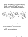
2. Lift the printer cover by its back edge and then pull it straight up
and off.
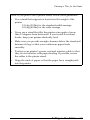
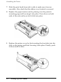
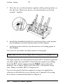
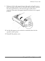
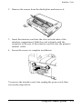
3. Grasp the tabs on each side of the paper-tension unit as shown
below. Press up firmly with your thumbs to lift the front of the
unit; then pull the paper-tension unit up and off the printer.
4. Slide the print head to the middle of the printer.
1-6
Setting Up the Printer
Assembling the Printer
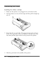
0t0
CAUTION: Moving the print head while the printer is on
might damage the printer. Also, if you just used the
printer, the print head may be hot; let it cool for a few
minutes before touching it.
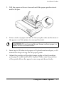
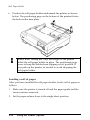
5. Turn the ribbon-tightening knob in the direction of the arrow to
remove any slack in the ribbon. Next, hold the ribbon cartridge
by its handle (two handles for the wide carriage) and push it
firmly down into position; then press on both ends of the
cartridge to fit the plastic hooks into the slots.
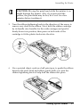
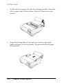
6.
Use a pointed object, such as a ball point pen, to guide the ribbon
between the print head and ribbon guide while you turn the
ribbon-tightening knob to help feed the ribbon into place.
Setting Up the Printer
1-7
Assembling the Printer
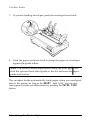
7. Slide the print head from side to side to make sure it moves
smoothly. Also check that the ribbon is not twisted or creased.
8. Replace the paper-tension unit by placing it on the printer’s
mounting pegs and lowering it into place. Press down on both
ends of the unit until you feel it click into place.
9.
1-8
Replace the printer cover by first inserting the front tabs into the
slots on the printer and then lowering it into place. Finally, push
it down until it clicks.
Setting Up the Printer
Assembling the Printer
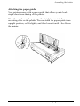
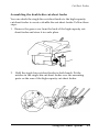
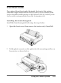
Attaching the paper guide
Your printer comes with a paper guide that allows you to load a
single sheet from the top of the printer.
Place the notches on the paper guide straight down into the
mounting slots on the printer. You can stand the paper guide in an
upright position, or lift slightly and then lower it until it lies flat on
the printer.
Setting Up the Printer
1-9
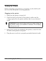
Testing the Printer
Before connecting your printer to a computer, use the built-in self
test to see that the printer is working properly.
Plugging in the printer
1.
Make sure the printer is turned off.
2. Check the label on the back of the printer to make sure the
voltage required by the printer matches that of your electrical
outlet.
t
l
CAUTION: If the rated voltage and your outlet voltage do
not match, contact your dealer for assistance. Do not plug
in the power cord.
3. If the power cord is not attached to the printer, connect it to the
AC inlet on the printer’s rear panel.
4. Plug the power cord into a properly grounded electrical outlet.
1-10
Setting Up the Printer
Testing the Printer
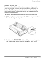
Running the self test
You can run the self test with continuous paper or single sheets.
Also, you can load paper for the test from the rear, front, top, or
bottom. The following steps describe how to run the test using a
single sheet of paper, loaded from the top. See Chapter 2 for full
details on paper handling.
The printer prints the self test using the currently selected font.
1. Make sure that the printer is turned off. Move the paper-release
lever to the single-sheet position.
2.
Hold down the PAPER FEED button while you turn on the printer.
The printer beeps several times and the READY light blinks.
Setting Up the Printer
1-11
Testing the Printer
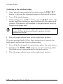
3.
Move the left edge guide until it locks in place next to the arrow
guide mark. Then adjust the right edge guide to match the width
of your paper.
CAUTION: Use paper that is at least 210 mm (8.27 inches)
wide for the standard-width carriage or 360 mm (14
4. Insert a sheet of paper between the edge guides until it meets
resistance. After about two seconds, the printer loads the paper
automatically and starts the self test.
1-12
Setting Up the Printer
Testing the Printer
The printer prints the default settings, followed by font samples
for each of the printer’s available fonts.
5. The self test continues until the paper runs out or until you press
the PAUSE button. When the printer beeps, you can load another
sheet of paper to continue printing font samples. When you wish
to stop the test temporarily, press the PAUSE button. To resume
the test, press the PAUSE button again.
6. While holding down the ALT button, press the EJECT button to
eject the paper. Then turn off the printer to end the self test.
Here is part of a typical self test.
- - CIJRRECIT SETTIl’ICi --I-.EF’SOCI l3c/II”ri.11 t e r mode
Character spacinq
I. 0 c u i
H o skip
SGrip-over--perforation
0
S h a p e o f zercl
V&id
Tear off
Depentl!5 on
hut<> line feed
Paoe
length
l/I-
11 irlChC?!5
Note: If the self test does not print properly, see Chapter 6.
Setting Up the Printer
1-13
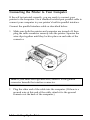
Connecting the Printer to Your Computer
If the self test printed correctly, you are ready to connect your
printer to the computer. Use a shielded twisted-pair parallel cable to
connect your computer to your printer’s built-in parallel interface.
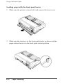
Connect the parallel interface cable as described below:
1. Make sure both the printer and computer are turned off; then
plug the cable connector securely into the printer. Squeeze the
wire clips together until they lock in place on each side of the
connector.
Note: If your cable has a ground wire, attach it to the ground
connector beneath the interface connector.
2.
Plug the other end of the cable into the computer. (If there is a
ground wire at this end of the cable, attach it to the ground
connector at the back of the computer.)
1-14
Setting Up the Printer
Configuring Your Software for the Printer
Most application programs allow you to specify the type of printer
you use so that the program can take full advantage of the printer’s
features. Many of these programs provide an installation or setup
section that presents a list of printers.
Choosing from a menu
To take full advantage of your printer’s features, choose your printer
when you set up your program. If your printer is not listed, choose
from the following list (the printers are listed in the order of
preference):
FX-870
FX-1170
FX-850
FX-1050
FX-800
FX-1000
EX-800
EX-1000
FX-85
FX-105
FX-80+
FX-lOO+
FX-80
FX-100
Epson printer
9-pin printer
If you plan to use the IBM printer emulation mode, choose IBM
Proprinter (XL), IBM Graphics printer, or IBM printer, in that order
of preference.
To use all the features of your printer, it is best to choose a program
that lists one of the FX printers on its menu. If your program does
not list one of these printers, contact the software manufacturer to
see if an update is available.
Setting Up the Printer
1-15
Configuring Your Software for the Printer
1-16
Setting Up the Printer
Chapter 2
Paper Handling
Selecting a Paper Feeding Method .......................................... 2-2
Setting the paper-release lever ............................................. 2-2
Using Single Sheets ................................................................... 2 - 4
Loading single sheets from the top .................................... 2 - 4
Using Continuous Paper .......................................................... 2 - 6
Tractor position and available paper paths.. ..................... 2 - 6
Changing tractor positions .................................................. 2 - 7
Loading paper with the front push tractor ....................... 2-10
Removing paper from the front push tractor ................... 2-12
Loading paper with the rear push tractor ......................... 2-13
Removing paper from the rear push tractor ..................... 2-15
Loading paper with the pull tractor.. ................................. 2-16
Removing paper from the pull tractor ............................... 2-19
Switching Between Continuous and Single Sheets .............. 2-20
Switching to single sheets .................................................... 2-20
Switching to continuous paper ........................................... 2-22
Printing on Special Paper.. ....................................................... 2-23
Setting the paper-thickness lever.. ...................................... 2-23
Multi-part forms.. .................................................................. 2-24
Labels ................................................................... ... .............. 2-25
Envelopes ............................................................................... 2-26
Paper Handling 2-1
Selecting a Paper Feeding Method
Your printer provides four paper paths so you can print on almost
any type of paper:
l
l
Choose the top paper guide to print on single sheets.
Install the tractor unit in the appropriate location to load
continuous paper from the front, rear, or bottom.
You can mount the tractor unit in three different positions to suit
your particular needs: use it as a front push tractor, rear push
tractor, or pull tractor.
Once you select a feeding method, you simply set the paper-release
lever, load your paper, and print. You can even print on single
sheets without removing your continuous paper supply. Also see
Chapter 4 for information on using an optional additional tractor
unit.
Setting the paper-release lever
You set the paper-release lever to select the active paper path in
your printer. The printer automatically loads paper from the
position you choose.
2-2
Paper Handling
Selecting a Paper Feeding Method
Single-sheet position
For all single sheets, whether loaded from the top or
either of the optional cut-sheet feeders; also for loading
single sheets from the front with the optional front sheet
guide.
.
:
45
.
:
c3
.
:
43
PULL
Front push-tractor position
For continuous paper with the tractor unit installed in
the front.
Rear push-tractor position
For continuous paper with the tractor unit installed in
the rear.
Pull-tractor position
For continuous paper with the tractor unit installed on
the top. In this case, you can load paper from the front,
rear, or bottom.
Paper Handling 2-3
Using Single Sheets
Your printer accommodates single sheets up to a maximum width of
257 mm (10.1 inches) on the standard-width carriage and 420 mm
(16.5 inches) on the wide carriage. You can load single sheets from
the top of the printer. Also, you can load single sheets from the
front with the optional front sheet guide. (This option may not be
available in some countries.)
If the paper-tension unit has been removed, you need to replace it
before you print on single sheets. See page 1-8 in Chapter 1.
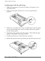
Loading single sheets from the top
1.
Place the paper-release lever in the single-sheet position. Make
sure the paper guide is in the upright position.
2. Turn on the printer. The READY light on the control panel comes
on.
2-4
Paper Handling
Using Single Sheets
3. Move the left edge guide until it locks in place next to the arrow
on the paper guide. Next adjust the right edge guide to match
the width of your paper.
4. Slide a sheet of paper between the edge guides until it meets
resistance. The printer loads the paper automatically and you are
ready to print.
0t
l
CAUTION: Always turn off the printer before you use the
knob on its left side to clear paper jams. If the printer is on,
you may damage it or lose the top-of-form position.
If the platen turns but the printer doesn’t load the paper, completely
remove the paper and reinsert it more firmly. To eject the paper,
hold down the ALT button and press the EJECT button.
Paper Handling 2-5
Using Continuous Paper
You can load continuous paper through the front, rear, or bottom
paper slots, depending upon the position of the tractor unit and the
placement of your paper supply.
Your printer can handle continuous paper up to 254 mm (10.0
inches) wide on the standard-width carriage and up to 406 mm (16.0
inches) wide on the wide carriage.
To print on continuous paper, you can install the tractor unit in one
of the following positions: front, rear, or pull. Be sure you set the
paper-release lever correctly before you print. See Setting the paperrelease lever at the beginning of this chapter for a description of each
position.
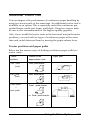
Tractor position and available paper paths
Below are the possible ways of feeding continuous paper. Always
set the paper-release lever to the position indicated for the paperfeed method you want to use.
Tractor
position
Paper-release
lever position
Front pushtractor
Rear pushtractor
.
:
&
J
.
:
Pull-tractor
43
PULL
2-6
Paper Handling
Paper paths
Using Continuous Paper
Note: Make sure you align your paper supply so paper can feed
smoothly into the printer. If you want to feed paper through the
bottom paper slot, use a printer stand that has a large enough
opening for the paper to feed without obstruction.
Changing tractor positions
Before installing the tractor in a different position, remove it from its
current position by pressing the blue lock tabs while you lift it out.
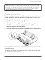
Installing in the front push-tractor position
1.
Make sure the printer is turned off.
2.
Open the front cover. If the optional front sheet guide is
installed, remove it by grasping the fins on both sides and
pulling it straight out of the printer.
3.
Push the tractor into the printer’s mounting slot as shown below.
See page 2-10 for instructions on loading continuous paper with the
front push tractor.
To remove the tractor unit, press the tractor’s lock tabs, tilt the unit
up, and lift it out of the printer.
Paper Handling 2-7
Using Continuous Paper
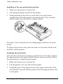
Installing in the rear push-tractor position
1. Make sure the printer is turned off.
2. Lift the paper guide up and off the printer.
3.
While pressing in the tractor’s lock tabs, lower the tractor
straight down into the printer’s mounting slots. Press on both
ends to make sure the tractor is firmly seated.
See page 2-13 for instructions on loading paper with the rear push
tractor.
To remove the tractor unit, press the tractor’s lock tabs, tilt the unit,
and lift it off the printer.
Installing the pull tractor
You can also use the tractor unit as a pull tractor. To do this, remove
the paper-tension unit and install the tractor unit in its place. Follow
the steps below to install the pull tractor.
1.
Make sure the power is turned off.
2.
Lift the printer cover up and off the printer.
3. Using the tabs on the paper-tension unit, grasp both ends of the
unit and lift it up and off the printer. Store the paper-tension unit
in safe place.
2-8
Paper Handling
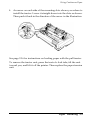
Using Continuous Paper
4. An arrow on each side of the mounting slots shows you where to
install the tractor. Lower it straight down into the slots as shown.
Then push it back in the direction of the arrow in the illustration.
See page 2-16 for instructions on loading paper with the pull tractor.
To remove the tractor unit, press the tractor’s lock tabs, tilt the unit
toward you, and lift it off the printer. Then replace the paper-tension
unit.
Paper Handling 2-9
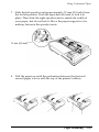
Using Continuous Paper
Loading paper with the front push tractor
1. Make sure the printer is turned off, and remove the front cover.
2.
Make sure the tractor is in the front push-tractor position and the
paper-release lever is in the front push-tractor position.
2-10
Paper Handling
Using Continuous Paper
3. Release the sprocket units by pushing the sprocket locks
backward.
4. Slide the left sprocket unit approximately 12 mm (0.5 inch) from
the far left position and pull the lever forward to lock it in place.
Now slide the right sprocket unit to match the width of your
paper, but do not lock it. Move the paper support so it is
midway between the sprocket units.
12 mm (0.5 inch)
\
Paper Handling
2-11
Using Continuous Paper
5.
Make sure your paper has a clean, straight edge. Open both
sprocket covers and fit the first four holes of the paper over the
sprocket pins.
6. Close the sprocket covers.
7.
,_:’
,;iY
Adjust the right sprocket to remove any slack in the paper. Lock
the sprocket unit in place by pulling the sprocket lock forward.
8. Attach the front cover.
9.
Turn on the printer. When the printer receives data, it
automatically loads the paper before printing.
Removing paper from the front push tractor
1. To remove continuous paper, press the TEAR OFF button to feed
the paper’s perforation to the tear-off edge of the printer cover.
Note: If the page perforation does not meet the tear-off edge, you
can adjust the tear-off position using the micro-feed feature. See
Chapter 3.
2.
Tear off the paper.
3.
While holding down the ALT button, press the EJECT button to
feed the continuous paper backward out of the printer and into
the paper-park position.
2-12
Paper Handling
Using Continuous Paper
Loading paper with the rear push tractor
1. Make sure the printer is turned off and the paper guide is
removed.
2. Make sure the tractor is in the rear push-tractor position and the
paper-release lever is also in the rear push-tractor position.
3.
Release the sprocket units by pulling the sprocket locks forward.
Paper Handling
2-13
Using Continuous Paper
4. Slide the left sprocket approximately 12 mm (0.5 inch) from the
far left position (Use the alignment marks on the printer case.)
Push the lever back to lock it in place. Then slide the right
sprocket unit to match the width of your printer, but do not lock
it. Move the paper support so it is midway between the sprocket
units.
12 mm (0.5 inch)
5.
Make sure your paper has a clean, straight loading edge. Open
the sprocket covers and fit the first four holes of the paper over
the sprocket pins.
2-14
Paper Handling
Using Continuous Paper
6.
Close the sprocket covers.
7.
Adjust the right sprocket to remove any slack in the paper; then
lock it in place.
8. Attach the paper guide in its flat position over the printer. Slide
the edge guides to the center.
9. Turn on the printer. When the printer receives data, it loads the
paper automatically before printing.
Note: You can also advance the paper to the loading position by
pressing the PAPER FEED button.
0t
a
CAUTION: Always turn off the printer before you use the
knob on its left side to clear paper jams. If the printer is on,
you may damage it or lose the top-of-form position.
Removing paper from the rear push tractor
1. To remove continuous paper, press the TEAR OFF button to feed
the paper’s perforation to the tear-off edge of the printer cover.
Note: If the page perforation does not meet the tear-off edge, you
can adjust the tear-off position using the micro-feed feature. See
Chapter 3.
2. Tear off the paper.
3. While holding down the ALT button, press the EJECT button to
feed the continuous paper backward out of the printer and into
the paper-park position.
CAUTION: Make sure you tear off your printed
document before holding down the ALT button and
Paper Handling
2-15
Using Continuous Paper
Loading paper with the pull tractor
1. Make sure the printer is turned off. Remove the printer cover
and paper guide.
2. Make sure the paper-release lever is set to the pull-tractor
position.
3. Make sure your paper has a clean, straight edge. Insert the paper
into the desired paper slot until it emerges between the platen
and the ribbon guide.
4. Attach the paper guide in the flat position. Then slide the edge
guides to the center of the paper’s width.
5.
Install the pull tractor in the pull-tractor position.
6.
Release the sprocket units by pulling the sprocket locks forward.
2-16
Paper Handling
Using Continuous Paper
7.
Slide the left sprocket unit approximately 12 mm (0.5 inch) from
the far left position. Push the sprocket lock back to lock it in
place. Then slide the right sprocket unit to match the width of
your paper, but do not lock it. Move the paper support so it is
midway between the sprocket units.
12 mm (0.5 inch)
8. Pull the paper up until the perforation between the first and
second pages is even with the top of the printer’s ribbon.
Paper Handling
2-17
Using Continuous Paper
Open the sprocket covers and fit the first four holes of the paper
over the sprocket pins.
9.
10. Close the sprocket covers.
11. Adjust the right sprocket unit to remove any slack in the paper.
Lock it in place by pushing the sprocket lock backward.
12. Turn on the printer.
13. Make any adjustments to the loading position with the microfeed feature, as described in Chapter 3.
14. Install the printer cover.
0
t
l
2-18
CAUTION: Always turn off the printer before you use the
knob on its left side to clear paper jams. If the printer is on,
you may damage it or lose the top-of-form position.
Paper Handling
Using Continuous Paper
Adjusting the top-of-form position
The printer feeds the paper to the top-of-form position when it loads
the paper or performs a form feed. This position determines where
the printing begins on the page.
You may need to adjust the top-of-form position when printing on
ready-made forms. To do this, see Adjusting the loading position on
page 3-15.
Note: When you are using the pull tractor, do not use the TEAR
OFF or ALT+ EJECT buttons.
Removing paper from the pull tractor
1. Tear off the paper entering the printer at the perforation.
2.
Hold down the PAPER FEED button to feed the continuous paper
forward and eject it.
Paper Handling
2-19
Switching Between Continuous and Single Sheets
Even with continuous paper loaded in the printer, you can easily
switch to single-sheet printing without removing the continuous
paper from the tractor. You can use this feature whenever the tractor
unit is installed in the front or the rear, or when using both the front
and rear (with the optional tractor).
Switching to single sheets
To switch from continuous paper to single sheets, follow the steps
below.
1. If a printed document is still in the printer, press the TEAR OFF
button to feed the paper forward to the tear-off position. Tear off
the document and press the TEAR OFF button again to feed the
continuous paper backward to the loading position.
CAUTION: Make sure you tear off your printed
document before holding down the ALT button and
2. While holding down the ALT button, press the EJECT button to
feed the continuous paper out of the printer and into the paperpark position. The paper is still attached to the tractor but no
longer in the paper path.
0t
l
2-20
CAUTION: Never feed labels backward through the
printer. Labels can easily come off the backing sheet and
cause a jam.
Paper Handling
Switching Between Continuous and Single Sheets
3. Push the paper-release lever back to the single-sheet position.
4. You can now load single sheets from the top as described in
Using Single Sheets earlier in this chapter.
Paper Handling
2-21
Switching Between Continuous and Single Sheets
Switching to continuous paper
You can easily switch back to printing on continuous paper.
1. If a single sheet is still in the printer, hold down the ALT button
and press the EJECT button to eject it.
2.
Lift up slightly on the paper guide and then lower it until it lies
flat on top of the printer. Slide the left and right edge guides
together so that they meet at the middle.
3.
Set the paper-release lever to either the front or rear push-tractor
position, depending on which tractor position you are using.
Your printer loads the continuous paper automatically.
2-22
Paper Handling
Printing on Special Paper
In addition to printing on single sheets and continuous paper, your
printer can also print on a wide variety of paper types, such as
envelopes, labels, and multi-part forms. Before printing on special
types of paper, you may need to change the paper-thickness setting.
t
l
CAUTION: When printing on labels or multi-part forms,
make sure that your printing stays within the printable
area of the page to prevent damage to the print head. For
more information on the printable area, see Chapter 7.
Always return the paper-thickness lever to position 0
when you return to printing on ordinary paper.
Setting the paper-thickness lever
To accommodate various thicknesses of paper, the printer is
equipped with a paper-thickness lever you can set to seven
positions. These positions are identified by the scale next to the
lever.
Paper Handling
2-23
Printing on Special Paper
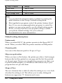
Use the following table to set the paper-thickness lever to match the
thickness of your paper:
Paper type*
Lever position
Ordinary (Single sheets or continuous)
Thin paper
Carbonless multi-part forms
2 sheets (original + 1 copy)
3 sheets (original + 2 copy)
4 sheets (original + 3 copy)
Labels
2
Envelope
2 to 5
See Chapter 7 for complete paper specifications.
*
Note: Print speed is reduced for paper-thickness lever settings of
2 and above.
Multi-part forms
You can use carbonless multi-part forms of up to four parts
(including the original). Make sure you set the paper-thickness lever
to the proper position based on the number of parts in your form.
Except for the paper-thickness setting, you load multi-part forms the
same way as ordinary paper. For details, see the sections on loading
continuous paper earlier in this chapter. Pay special attention to
setting the top-of-form position.
0t
l
CAUTION: Be sure the multi-part forms do not exceed
0.32 mm (0.0128 inches) in thickness.
2-24 Paper Handling
Printing on Special Paper
Labels
When printing labels, use the type mounted on a continuous
backing sheet with sprocket holes for use with a tractor. Do not try
to print labels as single sheets because labels on a shiny backing
sheet may not feed properly.
You can load labels from the front (push tractor or pull tractor) or
bottom (pull tractor) paper slot; however, for best results, use the
tractor in the pull-tractor position. You load labels the same way you
load continuous paper, except you must set the paper-thickness
lever to 2 before printing labels.
See Loading paper with the pull tractor earlier in this chapter for
details.
0
t
l
CAUTION:
l
Never feed labels backward with the ALT + EJECT or
TEAR OFF buttons. Labels can easily peel off the backing
and cause a jam.
l
l
l
Because labels are sensitive to extreme temperature
and humidity, always use them under normal
operating conditions.
Do not leave labels loaded in the printer between jobs;
they curl around the platen and may jam when you
resume printing.
To remove labels from the paper path after you finish
printing, tear off the labels at a point before the paper
slot. Then use the PAPER FEED button to advance the
remaining labels out of the printer.
Paper Handling
2-25
Printing on Special Paper
Envelopes
You can load envelopes individually using the single-sheet loading
feature from the top paper guide. If you want to load several
envelopes at the same time, you can install the optional highcapacity cut-sheet feeder. See Chapter 4 for a description of loading
envelopes with the cut-sheet feeder.
Before loading an envelope, set the paper-thickness lever to position
2 to 5, depending on the thickness of the envelope. To load an
envelope, follow the steps described in Loading single sheets from
the top earlier in this chapter.
Note:
l
Insert the envelope between the edge guides until it meets
resistance.
l
l
l
2-26
The print head must not print past the left or right edge of the
envelope or other thick paper. Make sure your application
program prints entirely within the printable area of the
envelope you are using.
Insert the top edge of the envelope into the printer.
If you use No. 6 envelopes, make sure the left edge guide is
aligned with the arrow on the paper guide.
Paper Handling
Chapter 3
Using the Printer
Control Panel . . . . . . . . . . . . . . . . . . . . . . . . . . . . . . . . . . . . . . . . . . . . . . . . . . . . . . . . . . . . . . . . . . . . . . . . . . . . . .
Lights . . . . . . . . . . . . . . . . . . . . . . . . . . . . . . . . . . . . . . . . . . . . . . . . . . . . . . . . . . . . . . . . . . . . . . . . . . . . . . . . . . . . . . .
Buttons . . . . . . . . . . . . . . . . . . . . . . . . . . . . . . . . . . . . . . . . . . . . . . . . . . . . . . . . . . . . . . . . . . . . . . . . . . . . . . . . . . . . .
Other control-panel features . . . . . . . . . . . . . . . . . . . . . . . . . . . . . . . . . . . . . . . . . . . . . . . .
3-2
3-2
3-3
3-4
Default-Setting Mode ................................................................ 3-5
Default-setting listing ............................................................ 3-5
Default setting descriptions .................................................. 3-6
Changing Group 1 default settings ..................................... 3-9
Changing Group 2 default settings .................................... 3-10
Changing Group 3 default settings .................................... 3-12
Changing Group 4 default settings ..................................... 3-14
Micro Feed .................................................................................. 3-15
Adjusting the print position ................................................. 3-15
Adjusting the loading position ............................................ 3-16
Tear Off ....................................................................................... 3-18
Using the tear-off mode ........................................................ 3-18
Using the TEAR OFF button ................................................... 3-19
Adjusting the tear-off position ............................................. 3-20
Character Fonts . . . . . . . . . . . . . . . . . . . . . . . . . . . . . . . . . . . . . . . . . . . . . . . . . . . . . . . . . . . . . . . . . . . . . . . . . . . 3-21
Data Dump Mode . . . . . . . . . . . . . . . . . . . . . . . . . . . . . . . . . . . . . . . . . . . . . . . . . . . . . . . . . . . . . . . . . . . . . . 3-23
Using the Printer
3-1
Control Panel
The control panel has four buttons and three lights for simple
control of basic printer operations.
oh-aft
O=Roman
%Sans Serif
0 CONDENSED
READY
0
(1,
OPERATE
Lights
READY (green)
On when the OPERATE button is on and power is supplied. This light
blinks when the printer is paused, in tear-off mode, out of paper, or
the print head is overheated.
FONT (green)
Shows which font is selected. This light is off for draft, on for NLQ
Roman, and blinks for NLQ Sans Serif font.
CONDENSED (green)
On for condensed printing and off for normal printing.
3-2
Using the Printer
Buttons
OPERATE
Turns the printer on or off. The printer is off when the button is out
and on when the button is in.
PAUSE/TEAR OFF
Press this button to stop printing temporarily. Press it again to
resume printing.
When you have finished printing on continuous paper, press this
button once to advance paper to the tear-off position. Press it again
to feed the paper backward to the loading position.
PAPER FEED
Press this button briefly to advance paper line by line. Hold it down
to advance continuous paper to the next top-of-form (TOF) position.
When the printer is out of paper, press this button to load
continuous paper from the paper-park position or a single sheet
from the optional cut-sheet feeder.
FONT
Press this button to select a font (draft, Epson Roman, or Epson Sans
Serif). This button also selects the normal or condensed mode for
these fonts. See Character Fonts later in this chapter for details.
Using the Printer
3-3
Control Panel
ALT
The FONT button also functions as the ALT button. Hold it down
while pressing another button for the following functions:
Eject (Hold down ALT and press PAPER FEED.)
If the paper-release lever is in the single-sheet position, paper is
ejected. If the paper-release lever is in the front- or rear-tractor
position, paper moves back to the paper-park position.
Entering the Micro-feed mode (Hold down ALT and press PAUSE/
TEAR OFF when paper is already loaded in the printer.)
Micro feed allows you to move the paper forward or backward
in 2/216-inch increments to adjust the loading and tear-off
positions. See Micro Feed later in this chapter for details.
Bin select (Hold down ALT and press PAUSE/TEAR OFF when the
printer is out of paper.)
When you use the optional double-bin cut-sheet feeder, you can
select the bin before loading paper. For more information, see
Cut-Sheet Feeders in Chapter 4.
Other control-panel features
Default-setting mode: See the next section for details.
Self test:
Hold down the PAPER FEED button while you turn
on the printer to perform the self test. The self test
lets you see that your printer is operating properly
and provides a printout of the current default
settings. See Testing the Printer in Chapter 1 for
details.
Data dump:
Hold down the PAUSE button while you turn on
the printer to enter the data dump mode. This
mode allows advanced users to find the cause of
communication problems between the printer and
the computer. For instructions, see Data Dump
Mode later in this chapter.
3-4
Using the Printer
Default-Setting Mode
Default-setting listing
Your printer has internal settings that control such functions as
emulation, character pitch, and page length. These settings are
called default settings because they take effect each time you turn on
the printer.
For most users, the factory settings are best, but you can change
these settings if necessary.
This section lists the settings, describes them, and then tells how to
change them. If you see something in the list that you need to
change, notice which group (1, 2, 3, or 4) it is in and check the
description for further information, then see the section on changing
the settings for the group it is in.
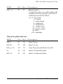
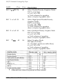
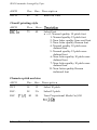
Group 1 Features
Printer mode
Character pitch
Skip-over-perforation
Shape of Zero
Tear off
Auto line feed
Settings
EPSON ESC/P or IBM emulation
1Ocpi or 12cpi
No skip or skip 1 inch
Unslashed 0 or slashed 0
Valid or invalid
Depends on interface or valid
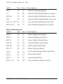
Group 2 Features
Character table
Settings
ESCYP: Italic U.S.A., Italic France,
Italic Denmark,
Italic Germany, Italic U.K.,
Italic Spain,
Italic Italy,
Italic Sweden,
Pc437,
Pca50,
PC437 Greek*,
Pca53*, Pca57*,
USSR GOST’,
Pca60,
PC851 *,
Pca55*,
Pca63,
PC869’,
Pcaw,
Pca65,
Pcaz
BRASCII**, Abicomp”
PC86Y,
IBM: PC437 (table l), PC437 (table 2) PC865
(table l), PC865 (table 2)
*
**
Available only in the European version.
Available only in the North/South American version.
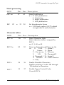
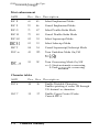
Group 3 Features
Page length
Settings
11, 12, 8.5, 70/6 (A4), 5.5, 7, 17, 14, 8, 6, 4, 3.5,
and 3 inches
Using the Printer
3-5
Default-Setting Mode
Group 4 Features
Settings
Input buffer
Valid or Invalid
Draft print speed
High or Normal
Auto carriage return
Valid or Invalid
Note:
l
You can check the character tables available by printing the
quick reference in the Group 2 default-setting mode.
l
Most application programs control the printer features listed
here. If you can use your application program to control the
printer, you may never need to use the default-setting mode.
In fact, you may find that your program settings override
your printer default settings. See your software
documentation for more information.
Default setting descriptions
Printer mode
When you select ESC/P, the printer operates in the Epson ESC/P
mode. When you select IBM, the printer emulates an IBM printer.
Character pitch
You can set the character pitch to 10 cpi or 12 cpi.
Skip-over-perforation
When you turn on this feature, the printer provides a l-inch margin
between the last line printed on one page and the first line printed
on the next page. Because most application programs set their own
top and bottom margins, you should use this feature only if your
program does not provide them.
Shape of Zero
The zero character has a slash (0) when the setting is on, or no slash
(0) when the setting is off. This allows you to easily distinguish
between an uppercase “0” character and a zero.
3-6
Using the Printer
Default-Setting Mode
Tear off
When you use continuous pap& with the front or rear push tractor,
you can use the tear-off feature.
When the auto tear off is valid, the printer automatically performs
the tear-off feature. The printer automatically feeds the paper
perforation to the tear-off position at the edge of the printer cover
after you complete a print job. You can then easily tear off the
printed page. When the printer again receives data, it automatically
feeds the paper backward to the top-of-form position and starts
printing.
When the auto tear off is invalid, you must perform the tear-off
function manually by pressing the TEAR OFF button. See Tear Off
later in this chapter for details.
Auto line feed
When this feature is valid, each carriage return (CR) code is always
accompanied by a line feed (LF) code. If your text lines overprint
each other, set auto line feed to valid. If your text lines are
mistakenly double spaced, set auto line feed to Depends on
interface.
Character table
Character tables contain the characters and symbols used in
different languages. Your printer includes a wide variety of
character tables. You can check the character tables available with
your printer by printing the quick reference in the Group 2
default-setting mode.
See the Appendix for specific characters in these character tables.
You can also select character tables with software commands. See
Chapter 8.
Page length
You can set the page length to 11, 12, 8.5, 70/6 (A4), 5.5, 7, 17, 14, 8,
6, 4, 3.5, or 3 inches.
Using the Printer
3-7
Default-Setting Mode
Input buffer
The input buffer stores data sent from your computer. The input
buffer can store up to 24 KB of data, so you can free your computer
for other tasks in a shorter time while the printer prints. When the
buffer is off, the buffer can store no data, so the computer must wait
for the printer to print each character before sending the next.
Draft print speed
When you select high-speed draft, the printer can print up to 380 cps
(characters per second) at 10 cpi in draft mode. If you select normal
speed draft, you can print up to 285 cps at 10 cpi in draft mode.
Auto carriage return
When the auto carriage return is valid, each line feed (LF) code or
ESC J (n/216-inch line feed) code is always accompanied by a
carriage return (CR) code. The printer always moves the next print
position to the left margin when it receives the LF or ESC J code.
When this feature is invalid, you must send the CR code after the
line feed code to move the print position to the left margin.
This feature is available in IBM emulation mode only.
3-8
Using the Printer
Default-Setting Mode
Changing Group 1 default settings
1. Make sure the printer is turned off.
2. Turn on the printer while you hold down the FONT button. This
enters the Group 1 default setting mode. The printer beeps once.
3. Load single-sheet or continuous paper. The printer then
automatically loads the paper and prints a quick reference.
Group 1 default settings
BLINK ON
BLINK
BLINK
Tear off
Valid
OFF
ON
Auto line feed
Invalid
Depends on interface
Valid
ON
OFF
Using the Printer
3-9
Default-Setting Mode
4. The FONT and CONDENSED lights show which feature you have
selected to change by turning on, off, or blinking. Press the FONT
button as many times as necessary until the FONT and
CONDENSED lights match your selection.
For example, if you want to change the character spacing, press
the FONT button until the FONT light is off and the CONDENSED
light is blinking.
5. Next, press the PAUSE button to change the setting. The READY
light shows your selection.
For example, if you want to change to 12 cpi, press the PAUSE
button once to turn the READY light on.
6. If necessary, repeat this process for any other Group 1 features
you want to change.
7. Exit the Group 1 default-setting mode at any time by turning off
the printer. Any changes you have made remain in effect until
you change them again.
Note: If you want to check the new default settings, enter the
default-setting mode again and print the quick reference. After
that, turn off the printer to exit the default-setting mode.
Changing Group 2 default settings
1. Make sure the printer is turned off.
2. Turn on the printer while you hold down the FONT and PAUSE
buttons. This enters the Group 2 default-setting mode. The
printer beeps once.
3-10
Using the Printer
Default-Setting Mode
3.
Load single-sheet or continuous paper. The printer then
automatically loads the paper and prints a quick reference
according to the emulation setting in Group 1.
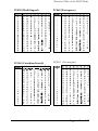
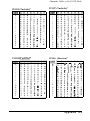
ESC/P mode character table
*
**
Available only in the European version.
Available only in the North/South American version.
Using the Printer
3-11
Default-Setttng Mode
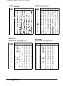
IBM mode character table
FONT
light
COND.
light
READY
light
IBM mode Character tables
OFF
OFF
ON
PC437 (table 1)
OFF
OFF
BLINK
PC437 (table 2)
OFF
ON
OFF
PC865 (table 1)
OFF
ON
ON
PC865 (table 2)
4. Press the Font button to select the character table. The FONT,
CONDENSED and READY lights turn on, off, or blink to show your
selection.
For example, if you select PC437 (USA, standard Europe), the
FONT light is on, the CONDENSED light is off, and the READY light
is off.
5. After you have made your selection, exit the Group 2 defaultsetting mode by turning off the printer.
Note: If you want to check the new default settings, enter the
default-setting mode again and print the quick reference. After
that, turn off the printer to exit the default-setting mode.
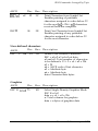
Changing Group 3 default settings
1. Make sure the printer is turned off.
2. To enter the Group 3 default-setting mode, turn on the printer
while you hold down the FONT and PAPER FEED buttons. The
printer beeps once.
3. Load single-sheet or continuous paper. The printer then
automatically loads the paper and prints a quick reference.
3-12
Using the Printer
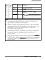
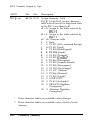
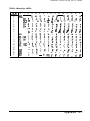
Group 3 default settings
Feature
FONT
light
COND. 1 READY 1 Settings
light
light
Page
length
OFF
OFF
ON
BLINK
ON
OFF
ON
11 inches (default setting)
BLINK
12 inches
OFF
8.5 inches
ON
70/6 inches
BLINK
5.5 inches
1 OFF
1 7inches
I
1
1 17 inches
I
1 BLINK 1 14inches
I
ON
1 OFF
I 8 inches
1
I
I Ginches
I
ON
I B L I N K I 4inches
ON
OFF
3.5 inches
ON
3 inches
4. Press the FONT button to select the page length. The FONT,
CONDENSED, and READY lights turn on, off, or blink to show your
selection.
For example, if you select 8 inches, the FONT light is on and the
CONDENSED and READY lights are off.
5. After you have made your selection, exit the Group 3 defaultsetting mode by turning off the printer.
Note: If you want to check the new default settings, enter the
default-setting mode again and print the quick reference. After
that, turn off the printer to exit the default-setting mode.
Using the Printer
3-13
Default-Setting Mode
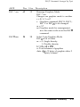
Changing Group 4 default settings
Group 4 default settings differ from 1 to 3. You determine the setting
by the number of beeps you hear instead of checking the panel
lights. Also, the printer does not print a list of Group 4 default
settings. To change Group 4 default settings follow the steps below.
1. Make sure the printer is turned off.
2. Hold down the PAUSE and PAPER FEED buttons while you turn
on the printer. You then enter the Group 4 default-setting mode.
3. Press the FONT, PAUSE, or PAPER FEED button if you want to
change the current setting. The printer beeps once or twice to
indicate your setting.
Button
Feature
Settings
Beeps
PAUSE
Input buffer
PAPER FEED
Draft print speed
FONT
Auto carriage return
Valid
Invalid
High
Normal
Valid
Invalid
Twice
Once
Twice
Once
Twice
Once
For example if you press the PAUSE button, the input buffer
becomes invalid and the printer beeps once.
Note:
l
If you don’t press any button within a few seconds after
entering this mode, the printer beeps five times and
automatically exits the Group 4 default-setting mode, leaving
the settings unchanged.
~ 0 Once you change a feature’s setting, you cannot change it
again without first exiting and re-entering the Group 4
default- setting mode.
4. After you make your changes, wait until the READY light comes
on. This shows that the printer has automatically exited the
setting mode and you can begin printing.
3-14
Using the Printer
Micro-Feed
The micro-feed feature allows you to move the paper forward or
backward in 2/216-inch increments. You use this feature to adjust
the loading and tear-off positions, as well as the print position
during a print job.
When you make adjustments to the loading or tear-off positions for
continuous paper, the printer remembers the new setting even if you
turn off the printer. The printer automatically advances the paper to
the new position when the power is turned on again.
When you adjust the loading position for single-sheet paper, the
printer remembers the new position only until you turn off the
power. The loading position returns to the factory setting when the
power is turned on again.
Adjusting the print position
Follow the steps below to adjust the print position during a print
job:
1. Press the PAUSE button to stop printing.
2. While holding down the ALT button, press the PAUSE button to
enter the micro-feed mode. The FONT and CONDENSED lights
blink alternately.
Using the Printer
3-15
Micro-Feed
3. Press the PAUSE/TEAR OFF button to feed the paper forward or
press the PAPER FEED button to feed the paper backward, as
indicated by the arrows beside the buttons.
4. To leave the micro-feed mode, press the ALT button again.
Then press the PAUSE button to continue printing.
Adjusting the loading position
The loading position is the position of the paper after it is
automatically loaded by the printer. If your printing is too high or
low on the page, you can change the loading position.
1. Make sure the printer is turned on.
2. Load either continuous or single-sheet paper. (Load continuous
paper by pressing the PAPER FEED button.)
3. While holding down the ALT button, press the PAUSE button to
enter the micro-feed mode. The FONT and CONDENSED lights
blink alternately.
4. Press the PAUSE/TEAR OFF button to feed the paper forward or
press the PAPER FEED button to feed the paper backward, as
indicated by the arrows beside the buttons.
3-16
Using the Printer
Micro-Feed
5. To leave the micro-feed mode, press the ALT button again or
send data to the printer.
The printer remembers the new loading position and advances all
subsequent pages to the new position.
Note:
l
The printer has a minimum and maximum loading position. If
you try to advance the loading position beyond these limits,
the printer beeps and the paper stops moving.
l
When the paper reaches the factory-set loading position, the
printer beeps and paper feeding pauses briefly. Use the
factory setting as a reference point when adjusting the loading
position.
Using the Printer
3-17
Tear Off
When you use continuous paper, the tear-off feature makes it easier
to tear off the last printed sheet and saves the paper normally lost
between documents. After you finish printing, this feature advances
the paper to the tear-off edge of the printer so you can easily tear off
the printed sheets. When you resume printing, the printer
automatically feeds the paper back to the loading position.
You can use the tear-off feature in either of two ways:
l
Turn on the tear-off mode in the default-setting mode.
.
Press the TEAR OFF button on the control panel.
t
0
CAUTION:
l
The tear-off feature can be used only when paper is
mounted on the front or rear push-tractor.
l
l
Never use the tear-off feature with the pull tractor; the
paper could come off the pull tractor and jam the
printer.
Never use the tear-off feature with labels. When fed
backward, labels may come off the backing and jam
the printer.
Using the tear-off mode
When you select the tear-off mode in the default-setting mode, the
printer automatically advances paper to the tear-off position
whenever it receives a full page of data or a form feed command
and then receives no more data.
First, select tear-off using the default-setting mode as described
earlier in this chapter. Also make sure the page length for
continuous paper is selected correctly in the default-setting mode.
Be sure you turn the printer off to exit from the default-setting mode
and turn it on again.
3-18
Using the Printer
Tear Off
1. Print on continuous paper loaded on the front or rear push
tractor (as described in Chapter 2). When you finish printing, the
printer advances the final p&ted page’s perforation to the tearoff position.
2. Tear off all printed pages.
Note: If the perforation does not meet the tear-off edge, you can
adjust the tear-off position using the micro-feed feature as
described on page 3-15.
I
3. When you resume printing, the printer automatically feeds the
paper back to the loading position and begins printing.
You can leave tear-off mode on even when you are using single
sheets because tear-off mode is disabled when you move the paperrelease lever to the single-sheet position.
When you are using the pull-tractor, you need to set the tear-off
mode to invalid in the default setting mode.
Using the TEAR OFF button
You can use the TEAR OFF button to advance continuous paper to the
tear-off position even if the tear-off mode is set to invalid in the
default-setting mode. Just follow the steps below:
1. Make sure printing has finished.
2. Press the TEAR OFF button. The printer advances the paper’s
perforation to the tear-off edge and the READY light blinks.
3. Tear off all printed pages.
Note: If the perforation does not meet the tear-off edge, you can
adjust the tear-off position using the micro-feed feature as
described in the next section.
Using the Printer
3-19
Tear Off
4. When you resume printing, the printer automatically feeds the
paper back to the loading position and begins printing. (You can
also manually feed the paper back to the loading position by
pressing the TEAR OFF button again.)
Adjusting the tear-off position
If the paper’s perforation does not meet the tear-off edge, follow the
steps below to adjust the tear-off position:
1. Make sure the paper is in the tear-off position and the READY
light is blinking.
2.
While holding down the ALT button, press the PAUSE button to
enter the micro-feed feature. The FONT and CONDENSED lights
blink alternately.
3.
Press the PAUSE/TEAR OFF button to move the tear-off position
down on the page, or press the PAPER FEED button to move the
tear-off position up on the page. The printer remembers the new
tear-off position even after you turn off the printer.
4.
Tear off any printed pages.
5.
When you begin printing, the printer automatically feeds the
paper back to the loading position and begins printing.
Note:
l
The printer has a minimum and maximum tear-off position. If
you try to advance the loading position beyond the limits, the
printer beeps and the paper stops moving.
l
3-20
When the paper reaches the factory-set tear-off position, the
printer beeps and paper feeding pauses briefly. Use the
factory setting as a reference point when you adjust the tearoff position.
Using the Printer
Character Fonts
Your printer has two draft fonts (normal and high-speed) and two
Near Letter Quality (NLQ) fonts (Epson Roman and Epson Sans
Serif). You can select these through application software and the
control panel.
The draft fonts are ideal for preliminary work. Use the defaultsetting mode (explained earlier in this chapter) to choose between
normal and high-speed draft.
Near Letter Quality takes a little longer to print but produces fullyformed characters suitable for most documentation requirements.
From the control panel you can select normal or condensed versions
of all the fonts. Condensed characters are 60 percent as wide as
normal characters.
Use the FONT button and the FONT and CONDENSED lights to select
the font you want. Each time you press the FONT button, the
selection changes and the FONT and CONDENSED lights come on
(m >, go off (u), or blink ( ‘I ) to indicate the current selection.
Font
FONT
Light
CONDENSED
Light
Draft
0
0
Draft Condensed
c7
m
Roman
m
0
Roman Condensed
m
m
Sans Serif
‘I
0
Sans Serif Condensed
”
m
m
on
0 off
‘) blinking
Note: The settings you select from the control panel remain in
effect even after YOU turn off the printer.
Using the Printer
3-21
Character Fonts
Because some application programs control character fonts and
because program commands often override panel settings, use your
application program’s print options instead of the control panel to
select character fonts if possible. If the fonts you select with the
panel are not the fonts that are printed, check your application
program’s user’s manual for instructions on selecting character
fonts.
Here are sample characters for each font.
Normal Draft
! “+I$%&’ ( ) t-l” ~ --. /~:~j.~~34.5~783: j .:::=..."-?@J,BC:I.J$J---Gt-I
1: J k:
nF'C1FGTUVWXYZ
[ '\ 1"' _,_’ abcdefghi j k Imnapqrstuvwxyz
c
Normal Draft condensed
!"i~'i.t'~)tt,-./0123456789:;~=~?@MICDEF6HIJKLtlN
OPQRSTUV#XYZ[\lA_'abcdefghijklanopqrstuv~xyz~!l
-.-
High-Speed Draft
/
j 11 +;;[:,:!.;;:8.: . ( ) *..;., !, . ,, ,/ ‘i:,:l,2:~~‘~.!~~,8’;:/ti~f~~ :: I; .::::::::::.‘;‘(~!n~~[(:;r>II1:I:~(:~I..I:I:,:rI(
I:)i:::i:lli:;.:iI!‘T’i,,J iji!.J)zx’f:.z: 1:: Y, ::I i.‘.,,,, ’ .3 I:) cd cc> T q 1-1 :i. .:i I,:. I. m n I:) 1:) q 1” <ii t. uv w x y z
Epson Roman
!“#$%&‘()a+,-./0123456789:;<=>?OABCDEFGHIJK
, OPQRSTUVWKYZC\l-- ‘ a b c d e f g h i j k l m n o p q r s t u v w x y z
l
Epson Roman condensed
!“#$%k’()tt,-./0123456789:;<r,?eABCDI(PGHIJKLHN
OPQRSTUVWXYZ[\]^-‘abcdefghijklnnopqrstuwxyzI 11
EpsonSan Serif
.
!"#8%&+$+,--./0123456789:;<=>?WBCDEFGHIJK
DPC?RSTUVWXYZ[\]^-' a b c d e f g h i j k l m n o p q r s t u v w x y z
Epson San Serif condensed
3-22
Using the Printer
Data Dump Mode
Data dump mode is a special feature that allows experienced users
to find the cause of communication problems between the printer
and application programs.
In data dump mode, the printer produces a printout of all the codes
it receives. To use data dump mode, follow these steps:
1. Make sure the printer is turned off.
2. Hold down the PAUSE button while you turn on the printer.
3. Load the paper.
4. Next, run an application program or a program you have
written in any programming language. Your printer prints all
the codes it receives in hexadecimal format and text, as shown
below.
Data Dump Mode
1B 40 41
0001 4F 50 51
5F
60 61
0002
0003 6F 70 71
ODCJO
42
52
62
72
43
53
63
73
44
54
64
74
45
55
65
75
46
56
66
76
47
67
67
77
46
56
66
76
49
59
69
79
4A
5A
6A
78
48
5B
6B
70
4C
5C
6C
7C
4D
5D
6D
7D
4E
5E
GE
7E
.@ABCDEFGHIJKLMN
OPQRSTUVWXYZE\l~abcdefghijklnan
opqanw:<yz~:~-
5. To turn off data dump mode, press the PAUSE button to stop
printing and then turn off the printer.
By reading the characters printed in the text field on the right side of
the printout or the printout of hex codes, you can check which codes
are being sent to the printer.
In the text field, characters appear as their true ASCII characters if
they are printable. Nonprintable codes, such as control codes, are
represented by dots.
Using the Printer
3-23
Chapter 4
Using the Printer Options
Cut-Sheet Feeders ..................................................................... .4-2
Installing a cut-sheet feeder.. ............................................... .4-2
Loading paper with the single-bin cut-sheet feeder.. ..... ..4- 3
Loading paper or envelopes with the high-capacity
cut-sheet feeder ................................................................ .4-6
Assembling the double-bin cut-sheet feeder .................... .4-9
Switching between continuous paper and the
cut-sheet feeder ................................................................ 4-11
Additional Tractor Unit ............................................................ 4-13
Tractor positions and paper paths.. .................................... .4-13
Using two tractor units in combination .............................. 4-14
Roll Paper Holder ...................................................................... 4-16
Installing the roll paper holder ........................................... .4-16
Loading a roll of paper ......................................................... .4-18
Interface Cards .......................................................................... .4-22
Installing an interface card .................................................. .4-22
The C823051 /C823061 serial interface card ...................... .4-24
Front Sheet Guide ..................................................................... .4-25
Installing the front sheet guide ........................................... .4-25
Loading single sheets from the front .................................. 4-26
Using the Printer Options
4-1
Cut-Sheet Feeders
Two cut-sheet feeders are available for use with your printer:
*
Printer
Single-bin
High-capacity
Standard
C80637*
C80638*
Wide
C80639*
C80640*
Substitute for last digit, which varies by country.
The single-bin cut-sheet feeder holds up to 50 single sheets of paper.
When this cut-sheet feeder is installed, you can still manually insert
single sheets using the paper guide.
The high-capacity cut-sheet feeder holds up to 150 sheets of paper or
up to 25 envelopes.
You can also connect both cut-sheet feeders and operate them as a
double-bin cut-sheet feeder. See Assembling the double-bin cutsheet feeder later in this chapter. This allows you to load two
different types of paper automatically.
Follow the directions included with your cut-sheet feeder to
assemble it; then install it as described in the next section.
Installing a cut-sheet feeder
Install your cut-sheet feeder (single-bin, high-capacity, or doublebin) by following the steps below.
1. Make sure the printer is turned off. Remove the paper guide and
printer cover.
2.
If the tractor unit is installed in the pull-tractor position, remove
it and reinstall it in the front or rear-tractor position. Then install
the paper-tension unit.
Note: Keep the paper guide handy; if you install the single-bin
unit, you need to reinstall the paper guide after you load paper.
Also, you will need it if you ever remove the cut-sheet feeder.
4-2
Using the Printer Options
Cut-Sheet Feeders
3. Make sure the paper-release lever is in the single-sheet position.
4.
Hold the cut-sheet feeder in both hands. Press down on the latch
levers and fit the notches in the cut-sheet feeder over the
mounting posts on the printer. Release the latch levers to lock
the cut-sheet feeder in place.
5.
Replace the printer cover by first inserting the front tabs into the
slots on the printer, then lowering it into place.
You are now ready to load paper with your cut-sheet feeder.
To remove a cut-sheet feeder, reverse the steps above.
Loading paper with the single-bin cut-sheet feeder
1. Make sure the paper guide is removed.
Using the Printer Options
4-3
Cut-Sheet Feeders
2. Slide the left paper guide so it is aligned with the triangle mark.
Next, slide the right paper guide to roughly match the width of
your paper. Slide the paper support midway between the paper
guides.
3.
Pull the paper-set levers all the way forward until the paper
guides retract and lock open.
n
4.
Take a stack of paper and fan it. Next, tap the side and bottom of
the paper on a flat surface to even up the stack.
4-4
Using the Printer Options
Cut-Sheet Feeders
0
t
0
I
CAUTION: Do not use envelopes, multi-part forms,
carbon paper, or labels in the single-bin cut-sheet feeder.
J
5. Insert up to 50 sheets of paper along the left paper guide.
6. Adjust the position of the right paper guide so that it matches
your paper’s width. Make sure the position of the guide allows
the paper to move up and down freely.
7.
Push the paper-set levers back to clamp the paper against the
guide rollers.
8.
Attach the stacker-support wires to the edge guides of the paper
guide. Then place the notches on the paper guide straight down
over the mounting posts on the printer to reinstall it. Slide the
edge guides to the middle of your paper.
You can still insert single sheets using the paper guide or the
optional front sheet guide. The cut-sheet feeder automatically loads
paper when you send print data to the printer (as long as the READY
light is lit). You can also load paper from the cut-sheet feeder by
pressing the PAPER FEED button.
Using the Printer Options
4-5
Cut-Sheet Feeders
Loading paper or envelopes with the high-capacity cut-sheet
feeder
1.
Pull the lock levers forward on the left and right paper guides to
release them.
2.
Slide the left paper guide until it is aligned with the triangle
mark; then lock it in place by pushing back on its lock lever.
Next, slide the right paper guide to roughly match the width of
your paper. Slide the paper support to midway between the
paper guides.
4-6
Using the Printer Options
Cut-Sheet Feeders
3. Pull the paper-set levers forward until the paper guides retract
and lock open.
4. Take a stack of paper and fan it. Next, tap the side and bottom of
the paper on a flat surface to even up the stack.
0
t
l
CAUTION: Do not use multi-part forms, carbon paper, or
labels in the cut-sheet feeder.
5. Insert up to 150 sheets of paper or 25 plain bond envelopes, or 30
airmail envelopes along the left paper guide.
6. Adjust the position of the right paper guide so that it matches
your paper’s width and lock it in place. Make sure the position
of the guide allows the paper to move up and down freely.
Using the Printer Options
4-7
Cut-Sheet Feeders
7.
If you are loading envelopes, push the envelope levers back.
8. Push the paper-set levers back to clamp the paper or envelopes
against the guide rollers.
1
Note: You can also insert single sheets using the front paper slot
with the optional front sheet guide or the slot between the paper
guide and stacker.
The cut-sheet feeder automatically loads paper when you send print
data to the printer (as long as the READY light is lit). You can also
load paper from the cut-sheet feeder by pressing the PAPER FEED
button.
4-8
Using the Printer Options
Cut-Sheet Feeders
Assembling the double-bin cut-sheet feeder
You can attach the single-bin cut-sheet feeder to the high-capacity
cut-sheet feeder to create a double-bin cut-sheet feeder. Follow these
steps:
1. Remove the gear cover from the back of the high-capacity cutsheet feeder and store it in a safe place.
2. Hold the single-bin cut-sheet feeder in both hands. Fit the
notches in the single-bin cut-sheet feeder over the mounting
posts on the rear of the high-capacity cut-sheet feeder.
Using the Printer Options
4-9
Cut-Sheet Feeders
3. Press the two cut-sheet feeders together while pushing firmly on
the tab locks. Make sure the two cut-sheet feeders are locked
securely together.
4. Install the assembled double-bin cut-sheet feeder on the printer.
See Installing a cut-sheet feeder earlier in this chapter.
5. Load paper into each bin. See the sections on loading paper in
this chapter.
You can now use either cut-sheet feeder to load paper.
Note: You can also insert single sheets using the front paper slot.
The high-capacity cut-sheet feeder becomes BIN 1 and the single-bin
cut-sheet feeder becomes BIN 2. Select the bin number by holding
down the ALT button and pressing the PAUSE button when the
printer is out of paper. When you select BIN 1, the printer beeps
once. When you select BIN 2, it beeps twice.
You can also specify the bin number by using your application
software as described in your software user’s manual or by using
the software command described in Chapter 8.
4-10
Using the Printer Options
Cut-Sheet Feeders
Switching between continuous paper and the cut-sheet
feeder
This printer allows you to switch easily between the cut-sheet feeder
and the tractor-feeding system without removing either the feeder
or the continuous-paper supply.
Switching to continuous paper
1. Make sure continuous paper is mounted on the tractor properly.
2. If a single sheet is in the paper path, hold down the ALT button
and press the EJECT button to eject it.
3. Place the paper-release lever in the front or rear push-tractor
position.
Note: When you want to print several pages of continuous paper,
fold the first printed page forward at the perforation after the
perforation emerges from below the printer cover. This helps the
printer feed the printed pages properly and prevents paper jams.
Using the Printer Options
4-11
Cut-Sheet Feeders
Switching to the cut-sheet feeder
1. If any printed sheets remain in the printer, press the TEAR OFF
button to advance the continuous paper to the tear-off position.
2.
Tear off the printed pages.
3.
While holding down the ALT button, press the EJECT button. The
printer feeds the continuous paper backward to the paper-park
position. The paper is still attached to the push tractor but is no
longer in the paper path.
0
1
l
CAUTION: Never feed labels backward. Labels can easily
come off their backing and jam the printer. See the
instructions below.
4. Place the paper-release lever in the single-sheet position.
If you are printing labels, follow these instructions to remove the
label supply and switch to the cut-sheet feeder:
1. Tear off the fresh supply at a perforation below the push-tractor.
2.
Hold down the PAPER FEED button to eject the remaining labels.
The labels are no longer attached to the push-tractor.
3.
Place the paper-release lever in the single-sheet position.
4-12
Using the Printer Options
Additional Tractor Unit
You can improve the performance of continuous paper handling by
using two tractor units at the same time. An additional tractor unit is
available as an option. This is especially useful for continuous preprinted forms, multi-part forms, and labels. Using two tractor units
at once is also recommended for the highest quality graphics.
Also, if you install the tractor units in the front and rear push-tractor
positions, you can load two types of continuous paper at the same
time and switch between them by moving the paper-release lever.
Tractor positions and paper paths
Below are the various ways of feeding continuous paper with two
tractor units.
Tractor
positions
Position of the
paper-release lever
Pull + front
push
Front push-tractor
.
:
Paper path
43
Pull + rear
push
Rear push-tractor
.
:
&J
Front push
+
rear push
Front push-tractor
.
:
43
or Rear push-tractor
Using the Printer Options
4-13
Additional Tractor Unit
Using two tractor units in combination
1.
Install one tractor in the front or rear-tractor position. See
Chapter 2 for details.
2. Place the continuous paper on the sprocket units of the front or
rear-push tractor unit. See Using continuous paper in Chapter 2.
3.
Reinstall the paper guide.
4. Install the other tractor in the pull tractor position. See Chapter
2 for details.
5. Turn on the printer. Press the PAPER FEED button to load paper;
then press the PAPER FEED button again to advance the paper.
CAUTION: Always turn off the printer before you use the
knob on its left side to clear paper jams. If the printer is on,
you may damage it or lose the top-of-form position.
6.
Release the sprocket lock levers of the pull tractor and adjust the
sprocket units to match the width of the paper. Be sure the
sprocket units on both tractors are aligned so the paper is not
crooked.
7. Fit the holes of the paper over the tractor pins of the sprocket
unit and adjust the sprocket units as necessary. See Using
Continuous Paper in Chapter 2.
8.
Close the sprocket covers.
4-14
Using the Printer Options
Additional Tractor Unit
9. If there is slack in the paper between the push and pull tractors,
place the paper-release lever in the pull-tractor position and use
the micro-feed feature to advance the paper until slack is
removed. Then move the paper-release lever back to its original
position.
10. See that the paper is not crooked or wrinkled; then lock the
sprocket units in place.
11. Reinstall the printer cover.
Using the Printer Options
4-15
Roll Paper Holder
The optional roll paper holder (#8310) for the standard-width
printer allows you to use 8.5-inch roll paper such as that used with
telex machines. This provides an inexpensive alternative to
continuous paper for applications requiring variable paper lengths.
Installing the roll paper holder
1. Make sure the printer is turned off.
2.
Remove the paper guide and the tractor unit.
3.
Fit the arc bearings into the stand as shown.
4-16
Using the Printer Options
Roll Paper Holder
4. Place the base plate onto the stand and fasten the two together
with the plastic spacing clips. Make sure you orient the stand
and base plate as shown below.
5. Hook the tension lever onto both ends of the stand as shown
below. Then, while pulling upward on the tension lever, fit the
wire ends of the tension lever into the holes in the stand.
Using the Printer Options
4-17
Roll Paper Holder
6.
Position the roll paper holder underneath the printer as shown
below. The positioning pegs on the bottom of the printer fit into
the holes in the base plate.
CAUTION: During use, only the weight of the printer
holds the roll paper holder in place. The positioning pegs
serve to keep the holder from slipping out of position. If
you pick up the printer, be careful to avoid dropping the
roll paper holder.
t
0
Loading a roll of paper
After you have installed the roll paper holder, load a roll of paper as
follows:
1. Make sure the printer is turned off and the paper guide and the
tractor unit are removed.
2.
Set the paper-release lever to the single-sheet position.
4-18
Using the Printer Options
Roll Paper Holder
3.
Cut the leading edge of the roll paper straight across.
4. Insert the roll paper holder shaft into the center of the paper roll
as shown.
Using the Printer Options
4-19
Roll Paper Holder
5.
Set the shaft and paper roll onto the roll paper holder. Orient the
roll so paper feeds off the bottom of the roll. Then turn on the
printer.
6.
Bring the leading edge of the paper up over the paper path
guide and insert it into the printer. The printer loads the paper
automatically.
4-20
Using the Printer Options
Roll Paper Holder
7. Install the paper guide as a separator.
You are now ready to print. When you finish printing, press the
PAPER FEED button to advance the paper a suitable amount; then tear
off the paper against the tear-off edge of the printer cover.
Roll paper cannot be fed backward. When you want to unload roll
paper, cut the paper behind the point where it feeds into the printer;
then while holding down the ALT button, press the EJECT button to
eject the remaining paper.
Using the Printer Options
4-21
Interface Cards
You can use optional interface cards to supplement your printer’s
built-in parallel interface.
The Epson interfaces below are compatible with your printer.
Name
Model Number
C823051 /C823061
Serial interface card
C823071/C823081
32KB serial interface card
C8231Ol/C823102
32KB parallel interface card
C823131/C823132
32KB IEEE-488 interface card
If you are unsure whether you need an optional interface or would
like to know more about interfaces, contact your dealer.
Note: Some of these interfaces are not available in some countries.
Installing an interface card
1.
Make sure the printer is turned off. Unplug the printer’s power
cord and disconnect the interface cable.
4-22
Using the Printer Options
Interface Cards
2. Remove the screws from the shield plate and remove it.
3.
Insert the interface card into the slots on both sides of the
interface compartment. Slide the card in firmly until the
connector at the rear of the interface card fits into the printer’s
internal socket.
4. Secure the screws to complete installation.
To remove the interface card, first unplug the power cord; then
reverse the steps above.
Using the Printer Options
4-23
The C823051/C823061 serial interface card
If you are using an optional interface, you may need to alter the
communications protocol of the printer or computer so they can
communicate properly. Use the information in your optional
interface manual or your computer’s manual to match the computer
with the interface.
If you are using the C823051 /C823061 optional interface card, read
through the sections below on baud-rate selection, handshake
timing, and error handling.
For all other data transfer conventions, such as word structure or
communications protocol, see the manual supplied with your
C823051 /C823061 optional interface.
Baud rate selection
You can select one of the following baud rates: 75, 110, 134.5, 150,
200, 300, 600, 1,200, 1,800, 2,400, 4,800, 9,600 and 19,200 bps (bits
per second). When you set the baud rate, see the baud rate selection
table in the C823051 /C823061 interface manual.
Handshake timing
When the vacant area for data in the input buffer drops to 256 bytes,
the printer outputs an X-OFF code or sets the DTR flag to “1”
(MARK) indicating that it cannot receive data.
Once the vacant area for data in the buffer increases to 528 bytes, the
printer outputs an X-ON code or sets the DTR flag to “0” (SPACE)
indicating that it is again ready to receive data.
Error handling
When a parity error is detected, your printer prints an asterisk (“1.
All other errors, including framing and overrun errors, are ignored.
4-24
Using the Printer Options
Front Sheet Guide
The optional front sheet guide fits inside the front of the printer.
It handles single sheets that are 148-257 mm (5.8-10.1 inches) wide
for the standard-width printer or 148-364 mm (5.8-14.3 inches) wide
for the wide-carriage printer from the front paper slot.
Installing the front sheet guide
Install the front sheet guide following the steps below:
1. Open the front cover; then remove the tractor unit, if installed.
2. Fit the plastic mounts on the guide into the mounting notches on
the printer, as shown below.
Using the Printer Options
4-25
Front Sheet Guide
Note: When the optional front sheet guide is installed in the
printer, the tractor unit cannot be mounted in the front position
and you cannot use the front push tractor.
Loading single sheets from the front
1. Place the paper-release lever in the single-sheet position.
2. Turn on the printer. The READY light on the control panel comes
on.
3. Move the left edge guide to the arrow mark on the front sheet
guide. If you wish, you can slide the edge guide to the left in
1/10-inch increments to increase the left margin on your
printout. Next, adjust the right edge guide to match the width of
your paper.
4-26
Using the Printer Options
Front Sheet Guide
4. Insert the paper between the edge guides firmly until it meets
resistance. The printer loads the paper automatically. You are
now ready to print.
0t
l
CAUTION: Always turn off the printer before you use the
knob on its left side to clear paper jams. If the printer is on,
you may damage it or lose the top-of-form position.
If the platen turns but the printer doesn’t load the paper, completely
remove the page and reinsert it more firmly.
To eject the paper, hold down the ALT button and press the EJECT
button.
Note: The printer’s paper guide serves as a built-in stacker and
can hold up to 50 sheets of ejected paper.
Using the Printer Options
4-27
Chapter 5
Maintenance and Transportation
Cleaning the Printer.. .................................................................. 5 - 2
Replacing the Ribbon Cartridge.. .............................................. .5-3
Transporting the Printer ............................................................ .5-4
Maintenance and Transportation
5-1
Cleaning the Printer
To keep your printer operating at its best, you should clean it
thoroughly several times a year.
1. Make sure the printer is turned off and unplug the printer’s
power cord. Then remove the paper guide, tractor unit, and the
cut-sheet feeder, if one is installed.
2.
Use a soft brush to carefully clear away all dust and dirt.
3.
If the outer case or paper guide is dirty or dusty, clean it with a
soft, clean cloth dampened with a mild detergent. Keep the
printer cover in place to prevent water from getting inside the
printer.
WARNING: Be careful not to get water on the printer
mechanism or electronic components.
01
l
CAUTION:
Never use alcohol or thinner to clean the printer; these
l
chemicals can damage the components as well as the
case.
l
l
5-2
Do not use a hard or abrasive brush.
Do not spray the inside of the printer with lubricants;
unsuitable oils can damage the mechanism. Contact
your dealer or a qualified service person if you think
lubrication is needed.
Maintenance and Transportation
Replacing the Ribbon Cartridge
When your printing becomes too faint, you need to replace the
ribbon cartridge.
Genuine Epson ribbons are designed and manufactured to work
properly with your Epson printer. Their high quality ensures proper
operation and long life of the print head and other printer parts.
Using any other ribbon may damage your printer or shorten its life.
The following Epson replacement ribbon cartridges are
recommended:
Printer
Ribbon cartridge
Standard #8750
Wide
#8755
To replace the ribbon cartridge, follow the steps described in
Installing the ribbon cartridge in Chapter 1.
Maintenance and Transportation
5-3
Transporting the Printer
If you need to transport your printer some distance, carefully repack
it using the original box and packing materials, as described below.
1. Turn off the printer.
2. Unplug the power cord from the electrical outlet; then
disconnect the interface cable from the printer.
3.
Remove the optional pull tractor and the cut-sheet feeder, if
installed.
4. Remove the ribbon cartridge.
5.
If you have removed the tractor unit, replace it according to the
instructions in Chapter 2.
6.
Replace the printer, ribbon cartridge, paper guide, and power
cord in the original packing materials and insert them in the
original box.
5-4
Maintenance and Transportation
Chapter 6
Troubleshooting
Problems and Solutions . . . . . . . . . . . . . . . . . . . . . . . . . . . . . . . . . . . . . . 6-2
Power Supply ............................................................................. 6-3
Printing .................................... .................................................... 6-4
Paper Handling .......................................................................... 6-8
Options ........................................................................................ 6-11
Troubleshooting 6-1
Problems and Solutions
This chapter presents solutions to possible printer problems. Locate
your problem in the list below and then see the appropriate page for
the solution.
Power supply
l
Power is not being supplied.
See 6-3
Printing
l
The printer does not print.
See 6-4
l
The print is faint or uneven.
See 6-5
l
Dots are missing in the printed characters or graphics.
See 6-5
l
Printed characters are not what you expect.
See 6-5
l
The print position is not what you expect.
See 6-6
Paper handling
l
Single sheets do not feed properly.
See 6-8
l
Continuous paper does not feed properly.
See 6-9
Options
l
l
l
When you use the cut-sheet feeder, the paper does not feed
See 6-11
properly.
When you use two tractor units in combination, continuous
See 6-12
paper does not feed properly.
When you use an optional interface, the printer does not operate
See 6-12
properly.
6-2 Troubleshooting
Power Supply
Power is not being supplied.
l
The READY light does not come on.
Check that the power cord is plugged into the electrical outlet
correctly.
If the electrical outlet is controlled by a switch or automatic
timer, use a different outlet.
Plug another electrical device into the outlet to determine
whether the outlet is operating properly.
l
The READY light comes on briefly and then goes off. The light stays off
even when the power is switched on again.
Check that the printer’s voltage rating matches the voltage of
your electrical outlet. If the voltages do not match, unplug the
printer and contact your dealer immediately. Do not reconnect
the power cord to an electrical outlet.
If problems persist, contact your Epson dealer, or a qualified service
person.
Troubleshooting 6-3
Printing
The printer does not print.
l
The READY light blinks.
Press the PAUSE button. If the READY light still does not stay on,
disconnect the printer cable. If the light then continuously stays
on, the problem is in the cable or the interface of the computer
or printer.
l
The READY light is on but nothing is printed.
Check that your application software is installed properly for
your printer. Check the software’s printer settings.
Check both ends of the interface cable between the printer and
the computer. Make sure your interface cable meets both the
printer and computer specifications. If you are using the
standard parallel interface, be sure your cable is a shielded
twisted-pair parallel cable.
l
The READY light blinks and the printer beeps.
The printer is out of paper. Load paper in the printer.
.
The printer sounds like it is printing, but nothing is printed.
The ribbon cartridge may not be installed properly. See the
section on ribbon installation in Chapter 1.
The ribbon may be worn out. Replace the ribbon cartridge.
The paper thickness setting may be incorrect. See Chapter 2.
l
The printer makes a strange noise, beeps several times, and stops
abruptly.
Turn off the printer and check for a paper jam, ribbon jam, or
other problem; then try to print again. If the printer still does
not print correctly, contact your dealer or a qualified service
person.
6-4
Troubleshooting
Printing
l
The READY light blinks but the printer does not print or it stops
printing abruptly.
The print head is overheated. Wait a few minutes; the printer
resumes printing automatically when the print head cools.
The print is faint or uneven.
l
Parts of printed characters are missing at the bottom.
The ribbon cartridge may not be installed properly. See the
section on ribbon installation in Chapter 1.
.
The printout is faint.
The ribbon may be worn out. Replace the ribbon cartridge.
Check that the paper-thickness lever is set correctly for the
paper you are using.
Dots are missing in the printed characters or graphics.
*
A line of dots is missing in the printout.
The print head is damaged. Stop printing and contact your
dealer or a qualified service person to have the print head
replaced.
l
Dots are missing in random positions.
There is either slack in the ribbon or the ribbon cartridge is
loose. Reinstall the ribbon cartridge.
Printed characters are not what you expect.
l
The typestyle or characters selected with your software cannot be
printed.
Check that the software is correctly installed for your printer.
Troubleshooting 6-5
Printing
l
The font selected by the control panel does not print.
Your software may be overriding your panel setting. Check the
font setting in your application program.
l
The wrong characters are printed.
The wrong character table or the wrong international character
set may be selected. Check the default settings. See page 3-5.
The print position is not what you expect.
l
Printing starts too high or too low on the page.
Adjust the top margin set by your application software. Use
micro feed to adjust the print position.
l
All text is printed on the same line.
Set the automatic line feed on in the default-setting mode so
that the printer automatically adds a line-feed code to each
carriage return. Check the default settings. See page 3-5.
l
The text is printed with blank lines between the lines of text.
Two line-feed signals are being sent. Set automatic line feed off
in the default-setting mode.
l
The page length does not match the length of your continuous paper.
Change the page-length setting in the default-setting mode. See
page 3-5.
Check the page length set by your application software and
adjust it if necessary.
6-6 Troubleshooting
Printing
l
Regular gays occur in the printout.
1 inch skip-over-perforation may be on. Turn this function off
in the default-setting mode.
l
Skip-over-perforation is set, but the perforation does not fall in the
center of the skip.
Adjust the top-of-form position. See page 2-19.
Make sure the default page length setting matches your
required paper length. See page 3-5.
If your application program is setting the top and bottom
margins, set the skip-over-perforation off in the default-setting
mode.
l
Printing starts too low on the page, or the bottom part
printed at the top of the next page.
of
one page is
Be sure to choose the correct printer from your application
program’s menu. See page 1-15 .
Use your application software to reduce or eliminate the top
margin and to reduce the page length.
If possible, specify single-sheet paper with your application
software.
If the printer still does not print correctly, try the self test described
in Chapter 1. If the self test works properly, the printer is all right
and the problem probably lies in the computer, the software, or the
cable. If the self test does not work, contact your dealer or a qualified
service person.
Troubleshooting 6-7
Paper Handling
The following section covers single-sheet and continuous-paper
problems. For cut-sheet feeder problems, see the section on options,
starting on page 6-11.
Single sheets do not feed properly.
l
When you insert single-sheet paper, the platen does not rotate and
paper does not feed.
Check that the paper-release lever is pushed back to the singlesheet position.
The paper may be too far to the right. Align the left edge guide
with the arrow mark on the paper guide.
l
When you insert the paper, the platen rotates but paper does not feed.
Reinsert the paper more firmly.
l
Printing starts too low on the page, or the bottom part of one page is
printed at the top of the next page.
Be sure to choose the correct printer from your application
program’s menu. See page 1-15.
If possible, specify single-sheet paper with your application
software.
Use your application software to reduce or eliminate the top
margin and reduce the page length.
Reduce the lines-per-page setting in your software.
6-8
Troubleshooting
Paper Handling
l
The paper feed is crooked or the paper jams.
Turn off the printer and put the paper-release lever in the pulltractor position. Pull out the paper and check the following two
items:
l
l
l
Make sure the paper size is within the specified range. See
page 7-3.
Make sure the paper is aligned with the edge guides.
The paper does not fully eject.
Hold down the PAPER FEED button to eject paper, or press the
PAPER FEED button while holding down the ALT button.
The paper may be too long. Use only paper that is within the
specified range.
Continuous paper does not feed properly.
l
When you send data, the platen does not turn and the push tractor does
not feed the paper.
If the READY light is blinking, press the PAUSE button.
l
The paper does not feed, although the platen rotates.
Check that the paper-release lever is set to the correct position.
l
The paper feed is crooked or the paper jams.
Make sure the paper supply is not obstructed by a cable or
some other object.
Make sure that your paper supply is within 1 meter (3 feet) of
the printer.
The position of your paper supply may be preventing it from
feeding straight.
Troubleshooting 6-9
See that the holes on the sides of the paper are aligned with
each other. Also, make sure the sprocket units are locked and
their covers are closed.
Check that the paper-thickness lever is set correctly for the
paper you are using. See page 2-23.
Check that the paper thickness is within the specified range.
See page 7-3.
l
The paper does not eject properly.
The page is too long. Tear off the paper and remove it from the
printer. Use only paper that is within the specified range.
6-10 Troubleshooting
Options
When you use the cut-sheet feeder, the paper does not feed
properly.
l
When you send data, the platen rotates but paper does not feed.
Make sure the cut-sheet feeder is correctly installed on the
printer.
See that the paper-release lever is pushed back to the singlesheet position.
Check for a paper jam near the print head.
See if too many sheets are loaded in the cut-sheet feeder’s bin.
If there is only one sheet left in the bin, add more paper.
l
Two or more sheets feed at the same time.
If you have loaded too many sheets in the cut-sheet feeder’s
bin, remove some of the sheets.
You may have forgotten to fan the stack of paper before
loading it into the bin. Remove the paper and fan it.
l
The paper feed is crooked.
The paper may be old or creased. Use only new, clean sheets of
paper.
If there is too much paper in the stacker, remove some.
Make sure your paper is the proper size and quality.
Troubleshooting
6-11
Options
When you use two tractor units in combination, continuous paper
does not feed properly.
l
The paper feed is crooked or paper jams.
Make sure that the sprocket units on both tractors are aligned.
When you use an optional interface, the printer does not operate
properly.
l
The printer does not print or the printout is not what you expect.
You may be trying to use an interface or interface cable with the
wrong specifications. Check the specifications to make sure you
can use the interface with this printer.
The computer and printer interface settings may not match.
Make sure the settings on the computer and printer match.
6-12 Troubleshooting
Chapter 7
Technical Specifications
Printer Specifications .................................................................
Printing ...................................................................................
Paper .......................................................................................
Mechanical ..............................................................................
Electrical .................................................................................
Environmental .......................................................................
7-2
7-2
.7-3
7-8
.7-9
.7-10
Interface Specifications .............................................................. 7-11
Specifications and pin assignments ..................................... 7-11
Interface timing ..................................................................... .7-14
Option Specifications.. .............................................................. .7-15
Cut-sheet feeders.. ....................... . ......................................... .7-15
Front sheet guide.. ................................................................. .7-17
Initialization ............................................................................... .7-18
Default settings.. .................................................................... .7-18
Technical Specifications 7-1
Printer Specifications
Printing
Printing method:
9-pin impact dot matrix
Printing speed:
Quality
Characters/inch
Characters/second/line
High-speed draft
Draft
IO
10
12
380
Near letter quality
10
12
57
68
285
342
Printing direction:
Bidirectional logic-seeking for text
Unidirectional for graphics
Line spacing:
l/6-inch, 1 /&inch, or programmable in
increments of l/216-inch
Payer-feed speed:
Friction:
69 ms/line at l/6-inch line spacing
77 ms/line at l/6-inch line spacing
Tractor:
Continuous feed: 3.7 inches per second
Buffer:
7-2
24KBorOKB
(Selectable in the default-setting mode)
Technical Specifications
Printer Specifications
Printable columns:
Maximum printed characters
Character size
Standard
Wide
IO cpi
80
136
12 cpi
96
163
17 cpi (10 cpi condensed)
137
233
20 cpi (12 cpi condensed)
160
272
Character fonts:
Draft, Epson Roman, or Epson Sans Serif in
normal or condensed mode. You can also
select other font/pitch combinations using
ESC/P commands. See the command summary
in Chapter 8 for details.
Character tables (ESC/P Mode):
Europe:
One italic and 15 graphic character tables
North/South America:
One italic and 7 graphic character tables
Other countries: One italic and 5 graphic character tables
13 international character sets
Character tables (IBM Emulation):
2 Character tables
1 Symbol set
Paper
Single sheets (toy insertion):
Width
Length
Thickness
Weight
l
148 to 257 mm (5.8 to 10.1 inches) for standard
148 to 420 mm (5.8 to 16.5 inches) for wide
max. 364 mm (14.3 inches)
0.065 to 0.14 mm (0.0025 to 0.0055 inches)
52.3 to 90 g/m2 (14 to 24 lb)
See page 7-17 for front insertion with the optional front
sheet guide.
Technical Specifications 7-3
Printer Specifications
Single-sheet multi-part forms:
l
l
Load single-sheet multi-part forms only into the front
slot with the optional front sheet guide. See 7-17 for
details.
Use carbonless multi-part forms only.
Continuous paper:
Width
101 to 254 mm (4 to 10 inches) for standard 101
to 406 mm (4 to 16 inches) for wide
Four sheets (one original plus up to three
Copies
copies)
0.065 to 0.32 mm (0.0025 to 0.012 inch) for one
Thickness
sheet
0.12 to 0.32 mm (0.0047 to 0.012 inch) total
52.3 to 82 g/m* (14 to 22 lb) for one sheet 40 to
Weight
58.2 g/m2 (12 to 15 lb) per sheet in multi-part
forms
l
Use carbonless multi-part forms only.
Note : You can use recycled paper with this printer. If you notice
an increase in ribbon consumption and paper jamming, use a
higher grade of paper.
7-4
Technical
Specifications
Printer Specifications
Labels:
63.5 x 23.8 mm (2.5 x 0.93 inches)
101 x 23.8 mm (4 x 0.93 inches)
101 x 27 mm (4 x 1.06 inches)
0.07 to 0.09 mm (0.0028 to 0.0031 inches) for
Thickness
backing sheet
0.16 to 0.19 mm (0.0063 to 0.0075 inches) total
l
Use continuous type labels only.
l
Use labels only under normal temperature and
humidity conditions.
Size
Envelopes:
Size
No. 6 - 166 x 92 mm (6.5 x 3.6 inches)
No. 10 - 240 x 104 mm (9.5 x 4.1 inches)
Thickness
0.16 to 0.52 mm (0.0063 to 0.0197 inches)
Weight
45 to 90 g/m2 (12 to 24 lb)
l
Use envelopes only under normal temperature and
humidity conditions.
Roll paper:
Size
Thickness
Weight
216+3 mm (8.5f0.12 inches)
0.07 to 0.09 mm (0.0028 to 0.0035 inches)
52.3 to 82 g/m* (14 to 22 lb)
Technical Specifications 7-5
Printer Specifications
Printable area:
Single sheets
A
B
C
B
A
I
t’
-I-
Printable area
C
I
The minimum top margin is 8.5 mm (0.33 inches).
The minimum left and right margins are 3 mm (0.12 inches). However, the
maximum printable width is 203 mm (8 inches) for the standard-width
carriage or 345 mm (13.6 inches) for the wide carriage.
The minimum bottom margin is 13.5 mm (0.53 inches).
Continuous paper
II
*I
*I
.I
.I
II ..
Printable area I I
A &---------j-:-i
*I
Printable area 1
I
.I
l
*I
*I
II
.I
I l
01
II ..
B
A
B
A
l
l
l
B
The minimum top and bottom margins (above and below the perforation)
are 9 mm (0.35 inches).
The minimum left and right margins are 13 mm (0.51 inches). However,
the maximum printable width is 203 mm (8 inches) for the standard-width
carriage or 345 mm (13.6 inches) for the wide carriage.
7-6 Technical Specifications
Printer Specifications
Envelopes
A
B
C
The minimum top margin is 8.5 mm (0.33 inches).
The minimum left and right margins are 3 mm (0.12 inches).
The minimum bottom margin is 13.5 mm (0.53 inches).
Roll paper
Printable area
A
B
C
The minimum top margin is 8.5 mm (0.33 inches).
The minimum left and right margins are 3 mm (0.12 inches). However, the
maximum printable width is 203 mm (8 inches) for the standard-width ’
carriage.
The minimum bottom margin is 13.5 mm (0.53 inches).
Technical Specifications 7-7
Printer Specific&ions
Mechanical
Paper-feed methods: Friction (with or without optional cut-sheet
feeder)
Push tractor (front or rear)
Pull tractor
Push-pull tractor (optional)
Ribbon:
Fabric ribbon cartridge
Standard: #8750
#8755
Wide:
Life expectancy at 14 dots/character:
3 million characters
MTBF:
Standard: 4000 power-on hours
6000 power-on hours
Wide:
Print head life:
100 million characters/wire
Dimensions and weight:
7-8
Standard
Wide
Height
154 mm (6.06 inches)
154 mm (6.06 inches)
Width
460 mm (18.11 inches)
635 mm (25.00 inches)
Depth
380 mm (14.96 inches)
380 mm (14.96 inches)
Weight
approx. 6.8 kg (14.96 lb)
approx. 9.2 kg (20.24 lb)
Technical Specifications
Printer Specifications
Electrical
120 V model:
AC 120 V
AC 103.5 to 132 V
1.8 A
(during self-test printing in draft mode
at 10 cpi)
Standard: approx. 45 W
approx. 45 W
Wide:
50 to 60 Hz
Rated frequency range:
49.5 to 60.5 Hz
Input frequency range:
Dielectric strength (between AC line and chassis):
AC 1000V rms 1 minute or AC 1200V
rms 1 second
Rated voltage:
Input voltage range:
Rated current:
Power consumption:
220/240V model:
AC 220 to 240 V
AC 198 to 264 V
0.9 A
(during self-test printing in draft mode
at 10 cpi)
Standard: approx. 45 W
approx. 45 W
Wide:
50 to 60 Hz
Rated frequency range:
49.5 to 60.5 Hz
Input frequency range:
Dielectric strength (between AC line and chassis):
AC 1.5 kV (rms), 1 minute
Rated voltage:
Input voltage range:
Rated current:
Power consumption:
Note: Check the label on the back of the printer for the voltage of
your printer.
Technical Specifications 7-9
Printer Specifications
Environmental
Temperature:
Operation:
Storage:
5” to 35°C (41” to 95°F)
-30” to 60°C (-22” to 140°F)
Humidity (without condensation):
10% to 80% RH
Operation:
5% to 85% RH
Storage:
Safety Approvals
Safety standards:
US model:
UL1950 with D3
CSA22.2 No. 220
European model:
EN 60950 (TijV, DEMKO, NEMKO,
SEMKO, SETI)
R.F.1
US model:
FCC part 15 subpart B class B
European model:
Vfg 243 (VDE 0878 part 3)
EN 55022 class B
7-10
Technical Specifications
Interface Specifications
Your printer is equipped with an 8-bit parallel interface.
Specifications and pin assignments
The built-in parallel interface has the following characteristics:
Data format:
S-bit parallel
Synchronization:
STROBE pulse
Handshake thing: BUSY and ACKNLG signals
Signal level:
TTL-compatible
Connector:
36-pin 57-30360 Amphenol connector or
equivalent
The table below provides the connector pin assignments and
describes their respective interface signals.
Signal Return Signal
Pin
Pin
Direction Description
1
19
STROBE IN
STROBE pulse to read data. Pulse width
must be more than 0.5 microseconds at
the receiving terminal.
2
3
4
5
6
7
8
9
20
21
22
23
24
25
26
27
DATA 1
DATA 2
DATA3
DATA4
DATA5
DATA6
DATA 7
DATA8
These signals represent information of the
1 st to 8th bits of parallel data,
respectively.
Each signal is at HIGH level when data is
logical 1 and LOW when it is logical 0.
IO
28
ACKNLG OUT
IN
IN
IN
IN
IN
IN
IN
IN
About a 12-microsecond pulse. LOW
indicates that data has been received and
that the printer is ready to accept more
data.
Technical Specifications
7-11
Single Return Signal
Pin
Pin
Direction Description
11
29
OUT
A HIGH signal indicates that the printer
cannot receive data. The signal goes
HIGH in the following cases:
1) During data entry
2) During input buffer full
3) During printer-error status
12
30
PE
OUT
A HIGH signal indicates that the printer is
out of paper.
13
-
SLCT
OUT
Pulled up to 5V through 3.3 kR
BUSY
Twisted-pair return signal ground level
32
7-12
16
INIT
-
-__
ERROR OUT
IN
Technical Specifications
When this level becomes LOW, the printer
controller is reset to its power-up state
and the print buffer is cleared. This level
is normally HIGH; its pulse width must be
more than 50 microseconds at the
receiving terminal.
This level becomes LOW when the printer
is:
1) in a paper-out status
2) in an error status
fnterface Speclflcattos
Signal
Direction Description
GND
-
Same as for pins 19-30
NC
-
Not used
OUT
Pulled up to 5V through 3.3 kQ
resistance
SLCT IN IN
The DCl/DC3 code is valid only when this
signal is HIGH. This signal is factory-set to
HIGH.
1
Note:
The column heading “Direction” refers to the direction of
signal flow as viewed from the printer.
“Return” denotes the twisted-pair return, to be connected at
signal ground level. For the interface wiring, be sure to use a
twisted-pair cable for each signal and to complete the
connection on the return side.
All interface conditions are based on the TTL level. Both the
rise and fall times of each signal must be less than 0.2
microseconds.
Data transfer must be carried out by observing the ACKNLG
or BUSY signal. Data transfer to this printer can be carried out
only after receipt of the ACKNLG signal or when the BUSY
signal is LOW.
Technical Specifications
7-13
Interface timing
The figure below shows the timing for the parallel interface.
BUSY
_-ACKNLG
DATA
-.---.--STROBE
7-14
Technical Specifications
Option Specifications
Cut-sheet feeders
*
The asterisk is a substitute for the last digit, which varies
according to country.
Dimensions and weight:
Option No.
Standard
Wide
C80637*
Single-bin
C80638*
High capacity
C80639*
Single-bin
C80640*
High capacity
Height
390 mm
(15.4 in.)
380 mm
(15.0 in.)
390 mm
(15.4 in.)
380 mm
(15.0 in.)
Width
Depth
449 mm
(17.7 in.)
449 mm
(17.7 in.)
624 mm
(24.6 in.)
624 mm
(24.6 in.)
446 mm
(17.6 in.)
435 mm
(17.1 in.)
446 mm
(17.6 in.)
435 mm
(17.1 in.)
Weight
0.55 kg
(1.22 lb)
1.55 kg
(3.42 lb)
0.75 kg
(1.65 lb)
2.15 kg
(4.74 lb)
Dimensions include the printer.
Bin capacity:
Single sheets:
C80637* and C80639*
Up to 50 sheets of 82-g/m* (22~lb) paper
C80638* and C80640*
Up to 150 sheets of 82-g/m* (22-lb) paper
Envelopes:
C80638* and C80640*
Up to 25 (plain and bond type)
Up to 30 (air mail)
MCBF:
100,000 cycles
Technical Specifications
7-15
Option Specification
Paper:
C80637*
C80639*
Width
C80638*
C80640*
Paper length
Thickness
Weight
Single sheets
Envelopes
182 to 216 mm
(7.17 to 8.50 in.)
182 to 420 mm
(7.17 to 16.54 in.)
182 to 216 m m
(7.17 to 8.50 in.)
182 to 420 mm
(7.17 to 16.54 in.)
210 to 364 mm
(8.27 to 14.33 in.)
0.07 to 0.12 mm
(0.0028 to 0.0047 in.)
64 to 91 g/m’
(18 to 24 lb)
N/A
N/A
165 to 241 m m
(6.54 to 9.49 in.)
165 to 241 mm
(6.54 to 9.49 in.)
92to104mm
(3.62 to 4.09 in.)
0.25 to 0.50 mm
(0.0098 to 0.0197 in.)
45 to 91 g/m2
(12 to 24 lb)
Paper storage conditions:
Temperature:
Humidity:
18” to 22°C (64” to 72°F)
40% to 60% RH
Environmental Temperature:
Operation:
Storage:
5" to 35°C (41” to 95°F)
-30" to 60°C (-22” to 140°F)
Humidity (without condensation):
Operation:
Storage:
15% to 80% RH
5% to 85% RH
Note:
l
24-lb paper printing is available only at normal operating
conditions.
l
7-16
Cut-sheet feeder envelope printing is available only with the
C80638* or C80640* cut-sheet feeders and only at normal
operating conditions.
Technical Specifications
Option Specifications
Front sheet guide
Dimensions and weight:
Height
Width
Depth
Weight
Standard
Option
No.
C814001
48.5 m m
332 m m
177 m m
280 g
Wide
C814011
48.5 m m
507 m m
177 m m
450 g
Printer
Paper:
Single sheets
Multi-part forms
C814001
148 to 257 mm
(5.8 to 10.1 inches)
C814011
148 to 364 mm
(5.8 to 14.3 inches)
Width
Paper length
Thickness
Weight
max. 364 mm
(max. 14.3 inches)
0.065 to 0.14 mm
(0.0025 to 0.0054 in.)
0.12 to 0.32 mm
(0.0047 to 0.0125 in.)
64 to 90 g/m”
(14 to 24 lb)
(40 to 58 g/m2) x 4
[(I2 to 15 lb)] x 4
Prifitable area:
Single sheets: Same as single sheets from the top insertion.
(Multi-part forms)
Note: Front sheet guide is available only at the nomal operating
conditions.
Technical Specifications
7-17
Initialization
There are two ways the printer can be initialized (returned to a fixed
set of conditions):
Hardware initialization
When the power is turned on or when
the printer receives an INIT signal
from the parallel interface (pin 31 goes
LOW).
Software initialization
When software sends the ESC @
(initialize the printer) command.
These two kinds of initialization have slightly different effects.
Software initialization does not initialize the printer mechanism or
‘clear the user-defined character set. Also, software initialization
does not clear the data buffer of all text.
Default settings
The table below shows the default conditions that take effect when
the printer is initialized.
Default condition
Item
Top-of-form position
Current paper position
Left and right margins
Cancelled
Line spacing
1/6-inch line spacing
Vertical tab positions
Cleared
Horizontal tab positions
Every eight characters
VFU channel
Channel 0
Font selection
Reset to the current panel setting
User-defined characters
Hardware: cleared
Software: deselected only
Character pitch
Depends on the control panel setting and
the default setting mode.
7-18
Technical Specifications
Chapter 8
Command Summary
Using the Command Summary . . . . . . . . . . . . .... . . . . . . . . . . . . . . . . 8-2
ESC/P Commands Arranged by Topic ................................. 8-3
Printer operation .................................................................... 8-3
Data control ............................................................................. 8-4
Vertical motion ...................................................................... 8-4
Horizontal motion .................................................................. 8-5
Overall printing style ............................................................ 8-6
Character pitch and size ........................................................ 8-7
Print enhancement ................................................................. 8-8
Word processing .................................................................... 8-9
Character tables ...................................................................... 8-9
User-defined characters ........................................................ 8-11
Graphics ................................................................................... 8-11
IBM Commands Arranged by Topic ...................................... 8-14
Printer operation .................................................................... 8-14
Data control ............................................................................. 8-14
Vertical motion ...................................................................... 8-14
Horizontal motion.. ............................................................... 8-15
Overall printing style ........................................................... 8-16
Character pitch and size ........................................................ 8-16
Print enhancement ................................................................. 8-18
Character tables ...................................................................... 8-18
User-defined characters ........................................................ 8-19
Graphics ................................................................................... 8-19
Command Summary 8-1
Using the Command Summary
The following sections list and describe all the commands available
in the Epson ESC/P and the IBM emulation modes. They are sorted
by topic in each mode.
If a command has parameters, they are explained. Parameters are
indicated by lowercase letters, usually n. The examples below show
how the parameters are indicated.
ESC @ is a command with no parameters.
ESC U 1 /0 is a command that uses 1 to turn the feature on and 0 to
turn it off.
ESC $ nl n2 is a command with two parameters.
ESC D nn is a command with a variable number of parameters.
Sending printer commands
Most actions your printer performs are handled by your software.
Software commands instruct the printer to print in a particular
typeface, feed the paper a certain amount after printing each line,
start printing on a particular place on the page, and so on.
Some software programs let you send these commands yourself.
This allows you to enhance your text in ways that may not normally
be available through the software. For example, some word
processing programs do not offer italics, but by inserting a
command in your document, you can use italics anywhere you like.
The commands your printer recognizes are listed in this command
summary.
How you format commands depends on the software you are using.
Some software programs accept only the decimal format, while
others let you type in ASCII characters. (Some programs don’t let
you insert printer commands at all.) In addition, your software
probably specifies certain punctuation you must use to enter the
command. If your software allows you to send commands to the
printer, the software manual should explain exactly what format
and punctuation are required.
8-2 Command Summary
ESC/P Commands Arranged by Topic
Printer operation
ASCII
Dec. Hex. Description
ESC @
64
40
Initialize Printer
DC1
17
11
Select Printer
DC3
19
13
Deselect Printer
ESC s 1/0
115
73
Turn Half-Speed Mode On/Off
ESC <
60
3C
Select Unidirectional Mode (one line)
ESC U 1/0
85
55
Turn Unidirectional Mode On/Off
ESC 8
56
38
Disable Paper-Out Detection
ESC 9
57
39
Enable Paper-Out Detection
ESC EM n
25
19
Turn Cut-Sheet Feeder Mode On/Off
n = “0”: Off
“1”: Select bin 1
“2”: Select bin 2
114”: On
“R”: Eject a sheet
*
For the ESC EM command, the variables are the characters;
for example, use “1” (49 decimal or 31 hex), not decimal 1.
ESC =
61
3D
Set MSB to 0
ESC >
62
3E
Set MSB to 1
ESC #
35
23
Cancel MSB Control
BEL
7
07
Beeper
Command Summary 8-3
I
ESC/P Commands Arranged by Topic
Data control
Hex.
Description
ASCII
Dec.
CR
13
OD
Carriage Return
CAN
24
18
Cancel Line
DEL
127
7F
Delete Character
Vertical motion
ASCII
Dec. Hex. Description
FF
12
oc
Form Feed
ESC Cn
67
43
Set Page Length in Lines
n = number of lines (l-127)
ESC C 0 n
67
43
Set Page Length in Inches
n = number of inches (l-22)
ESC N n
78
4E
Set Skip-Over Perforation
n = number of lines (l-127)
ESC 0
79
4F
Cancel Skip Over Perforation
LF
10
0A
Line Feed
ESC 0
48
30
Select 1 /%inch Line Spacing
ESC 1
49
31
Select 7/72-inch Line Spacing
ESC 2
50
32
Select l/6-inch Line Spacing
ESC3n
51
33
Set n/216-inch Line Spacing
n = O-255
8-4
Command Summary
ESC/P Commands Arranged by Topic
ASCII
Dec. Hex. Description
ESC A n
65
41
Set n/72-inch Line Spacing
n = O-85
ESC J n
74
4A
Perform n/216-inch Line Feed
n = O-255
VT
11
0B
Tab Vertically
ESC B nn
66
42
Set Vertical Tabs
Up to 16 tabs (1-255)
in ascending order; last parameter
should be 0. ESC B 0 clears all tab
settings.
62
Set Vertical Tabs in Channels
ESC b c n1 n2...n16 Up to 16 tabs (1-255)
in ascending order in channel c (0-7);
last parameter should be 0. ESC b c 0
clear all tab settings in channel c.
2F
Select Vertical Tab Channel
c = channel (0-7)
ESC
b
ESC / c
nn
98
47
Horizontal motion
ASCII
Dec. Hex. Description
ESC l n
108
ESCQn
BS
6C
Set Left Margin
n = left margin column
81
51
Set Right Margin
n = right margin column
8
08
Backspace
Command Summary 8-5
ESC/P Commands Arranged by Topic
ASCII
Dec. Hex. Description
ESC $ nl n2 36
24
ESC \ nl n2 92
5C
HT
09
ESC
9
D
nn
68
44
Set Absolute Horizontal Print Position
n = (n 1 + n2 x 256)/60 inches
n: Specifies print position as n/60 inches
from the left margin.
Set Relative Horizontal Print Position
n = (nl + n2 x 256)/ 120 inches
n: Moves current print position by n/
120 inches. If displacement is to the left,
subtract it from 65536.
Tab Horizontally
Set Horizontal Tabs
Up to 32 tabs (1-255) in ascending
order; last parameter should be 0. ESC D
0 clears all tab settings.
Overall printing style
ASCII
Dec.
Hex.
Descriution
ESCxn
120
78
Select Near Letter Quality or Draft
n = 0: Draft mode
1: Near Letter Quality (NLQ) mode
ESC k n
107
6B
Select Typestyle Family
n = 0: Roman
1: Sans Serif
8-6
Command Summary
ESC/P Commands Arranged by Topic
ASCII
Dec. Hex. Description
ESC ! n
33
21
Master Select
To find the value of n, add together the
numbers of the typestyles you want to
combine from the list below:
n= 0: 10 pitch
1: 12 pitch
2: proportional
4: condensed
8: emphasized
16: double-strike
32: double-width
64: italic
128: underline
Character pitch and size
ASCII
Dec. Hex. Description
ESC P
80
50
Select 10 cpi
ESC M
77
4D
Select 12 cpi
ESC p 1/O
112
70
Turn Proportional Mode On/Off
SI
15
OF
Select Condensed Mode
ESC SI
15
OF
Select Condensed Mode
Command Summary 8-7
ESC/P Commands Arranged by Topic
ASCII
Dec. Hex. Description
DC2
18
12
Cancel Condensed Mode
so
14
0E
Select Double-Width Mode (one line)
ESC SO
14
0E
Select Double-Width Mode (one line)
DC4
20
14
Cancel Double-Width Mode (one line)
ESC W l/O 87
57
Turn Double-Width Mode On/Off
77
Turn Double-Height Mode On/Off
ESC w l/O
119
Print enhancement
ASCII
Dec. Hex. Description
ESC E
69
45
Select Emphasized Mode
ESC F
70
46
Cancel Emphasized Mode
ESC G
71
47
Select Double-Strike Mode
ESC H
72
48
Cancel Double-Strike Mode
ESC SO
83
53
Select Superscript Mode
ESC Sl
83
53
Select Subscript Mode
ESC T
84
54
Cancel Superscript/Subscript Mode
ESC 4
52
34
Select Italic Mode
ESC 5
53
35
Cancel Italic Mode
ESC- l/O
45
2D
Turn Underline Mode On/Off
8-8 Command Summary
ESC/P Commands Arranged by Topic
Word processing
ASCII
Dec. Hex. Description
ESC an
97
ESC
SP
n
32
61
Select Justification
n = 0: Left justification
1: Centering
2: Right justification
3: Full justification
20
Set Intercharacter Space
n = 1/120-inch spaces (0-127) added
on right side of each character
Character tables
ASCII
Dec. Hex. Description
ESC tn
116
74
Select Character Table
Select character table n assigned by
ESC ( t
n= 0, 1, 48 or 49
ESC R n
82
52
Select an International Character Set
n=
0:
USA
7: Spain I
1:
France
8: Japan
2 : G e r m a n y 9 : Norway
3:
UK
10: Denmark II
4: Denmark I 11: Spain II
5: Sweden 12: Latin America
6: Italy
ESC 6
54
36
Enable Printable Characters
Enables printing of codes 128 through
159 decimal as characters.
ESC 7
55
37
Enable Upper Control Codes
Cancels ESC 6.
Command Summary 8-9
ESC/P Commands Arranged by Topic
Hex.
Description
ASCII
Dec.
ESC ( t nn
40 116 28 74 Assign Character Table
*
ESC ( t 3 0 dl d2 d3 Assign character
table with d2 and d3 to registered table
set by ESC t according to dl
dl = 0: Assign to the table selected by
ESCtO
dl = 1: Assign to the table selected by
ESCtl
d2 d3 Character table
0
0 Italic
1
0 PC 437 (USA, standard Europe)
1
16 PC 437 Greek*
3 0 PC 850 (Multilingual)
4 0 PC 851 (Greek)*
5
0 PC 853 (Turkish)*
6 0 PC 855 (Cyrillic)*
7 0 PC 860 (Portuguese)
8 0 PC 863 (Canada-French)
9
0 PC 865 (Norwegian)
10 0 PC 852 (East Europe)”
11 0 PC 857 (Turkish)”
14 0 PC 866 (Russian)*
15 0 PC 869 (Greek)*
16 0 USSR COST*
24 0 PC 861 (Icelandic)*
25 0 BRASCII (Brazilian
Portuguese)**
26 0 Abicomp (Brazilian
Portuguese)**
These character tables are available only in Europe.
** These character tables are available only in North /South
America.
8-10
Command Summary
ESC/P Commands Arranged by Topic
User-defined characters
ASCII
D e c . H e x . Descriution
ESC & nn
38
26
Define User-Defined Characters
ESC & 0 nl n2 al data
nl = ASCII code of first character
n2 = ASCII code of last character
al = Attribute byte that specifies
character width and pins to be
used
data: character data bytes
ESC: 0 n 0
58
3A
Copy ROM to RAM
n = 0: Copy Roman
1: Copy Sans Serif
ESC % n
37
25
Select User-Defined Set
n = 0: Normal set
1: User-defined set
ESCIn
73
49
Printable Code Area Expansion
Codes 0 to 31 and 128 to 159 decimal
n = 0: Non-printable codes
1: Printable codes for user
defined characters
Graphics
ASCII
Dec. Hex. Description
ESC K nl n2 75
4B
Select Single-Density Graphics Mode
ESC K nl n2 data
n=nl+n2x256
n: Total columns for graphics
data = n bytes of graphics data
Command Summary
8-11
ESC/P Commands Arranged by Topic
ASCII
D e c . H e x . Describtion
ESC L nl 112 76
4C
Select Double-Density Graphics Mode
ESC L nl n2 data
n = nl + n2 x 256
n: Total columns for graphics
data = n bytes of graphics data
ESC Y nl n2 89
59
Select High-Speed Double-Density
Graphics Mode
ESC L nl n2 data
n=nl +n2x256
n: Total columns for graphics
data = n bytes of graphics data
ESC Z nl n2 90
5A
Select Quadruple-Density Graphics Mode
ESC Z nl n2 data
n = nl + n2 x 256
n: Total columns of graphics
data = n bytes of graphics data
2A
Select Graphics Mode
ESC * m nl n2 data
m = Graphics mode (see table blow)
n = nl + n2 x 256
n: Total columns of graphics
data = n bytes of graphics data
ESC
*mn
42
Adjacent dots cannot be printed in these modes.
8-12
Command Summary
ESC/P Commands Arranged by Topic
ASCII
Dec. Hex. Description
ESC ? sm
63
3F
Reassign Graphics Mode
ESC ? sm
Changes one graphics mode to another.
s = K, L, Y or Z
s: Graphics command (ESC K, ESC L,
ESC Y or ESC Z) to be changed
m = O-7
m: Graphics mode for reassignment.
m is the same as the m in the ESC *
command.
ESC A mn
94
5E
Select 9-pin Graphics Mode
ESC A m nl n2 data
m = 0: Single density
1: Double density
n=nl +n2x256
n: Total columns of graphics
data = (n x 2) bytes of graphics data; 2
bytes/column
Command Summary
8-13
IBM Commands Arranged by Topic
Printer operation
ASCII
Dec. Hex. Description
DC1
17
11
Select Printer
ESC Q n
81
51
Deselect Printer
n = 3: Deselect standard printer
22: Deselect wide printer
ESC U n
85
55
BEL
7
07
Turn Unidirectional Mode On/Off
n= l:On
0: Off
Beeper
Data control
ASCII
Dec. Hex. Description
CR
13
OD
Carriage Return
CAN
24
18
Cancel Line
Vertical motion
ASCII
Dec. Hex. Description
FF
1 2
0 C
ESC C n
67
43
Set Page Length in Lines
n = number of lines (1-127)
ESC C 0 n
67
43
Set Page Length in Inches
n = number of inches (1-22)
4E
Set Skip-Over-Perforation
n = number of lines (1-127)
ESCNn
78
Form Feed
ESC 0
79
4F
Cancel Skip-Over-Perforation
ESC 4
52
34
Set Top-of-Form
LF
10
0A
Line Feed
8-14
Command Summary
IBM Comnzands Arranged by Topic
ASCII
Dec. Hex. Description
ESC 0
48
30
Select 1 /&inch Line Spacing
ESC 1
49
31
Select 7/72-inch Line Spacing
ESC 2
50
32
Select ESC A Line Spacing
ESC3n
51
33
Set n/216-inch Line Spacing
n = O-255
ESC A n
65
41
Set n/72-inch Line Spacing
n = O-85
ESCJn
74
A
Perform n/ 216-inch Line Feed
n = O-255
ESC5n
53
35
Set/Reset Automatic Line Feed
n = 0: Reset
1: Set
VT
11
OB
Tab Vertically
ESC B nn
66
42
Set Vertical Tabs
Up to 16 tabs (1-255) in ascending
order; last parameter should be 0. ESC
B 0 clears all tab settings.
Horizontal motion
Dec. Hex. Description
ASCII
ESC X nln2 88
58
Set Left and Right Margins
nl = left margin column
n2 = right margin column
BS
8
08
Backspace
HT
9
09
Tab Horizontally
44
Set Horizontal Tabs
Up to 32 tabs (1 255) in ascending
order; last parameter should be 0. ESC D
0 clears all tab settings.
ESC
Dnn
68
Command Summary
8-15
IBM Commands Arranged by Topic
ASCII
Dec. Hex. Description
ESC R
82
52
Reset All Tabs
Overall printing style
ASCII
D e c . H e x . Descriution
ESCIn
73
49
Select Font
n = 0: Normal quality 10 pitch font
1: Normal quality 12 pitch font
2: Near letter quality Sans serif font
3: Near letter quality Roman font
4: Normal quality 10 pitch userdefined font
5: Normal quality 12 pitch userdefined font
6: Near letter quality 10 pitch userdefined font
7: Near letter quality 10 pitch userdefined font
11: Near letter quality Roman
italicized font
Character pitch and size
ASCII
Dec. Hex. Description
DC2
18
12
Select 10 pitch
ESC :
58
3A
Select 12 pitch
50
Turn Proportional Mode On/Off
n=l:On
0: Off
ESC
I’l/O
80
8-16
Command Summary
IBM Commands Arranged by Topic
ASCII
Dec. Hex. Description
SI
15
OF
Select Condensed Mode
ESC SI
15
OF
Select Condensed Mode
so
14
OE
Select Double-Width Mode (one line)
ESC SO
14
OE
Select Double-Width Mode (one line)
DC4
20
14
Cancel Double-Width Mode (one line)
ESCWn
87
57
Turn Double-Width Mode On/Off
n=l:On
0: Off
ESC[@nn
9164
5B 40 Select Double-Height, Double-Width
Mode
ESC[Onln2mlm2m3m4
nl = 4
n2 = 0
ml=0
m2=0
m3 = Character height and line feed
34
1
Double-height
1
Double
m4 = Character width
0: Unchanged
1: Standard
2: Double-width
Command Summary
8-17
IBM Cornmnmh Amnged by Topic
Print enhancement
ASCII
Dec. Hex. Description
ESC E
69
45
Select Emphasized Mode
ESC F
70
46
Cancel Emphasized Mode
ESC G
71
47
Select Double-Strike Mode
ESC H
72
48
Cancel Double-Strike Mode
ESC SO
83
53
Select Superscript Mode
ESCSl
83
53
Select Subscript Mode
ESC T
84
54
Cancel Superscript/Subscript Mode
ESC-n
45
2D
Turn Underline Mode On/Off
n=l:On
0: Off
ESC-n
95
5F
Turn Overscoring Mode On/Off
n = 1: Starts automatic overscoring
0: Ends automa tic overscoring
Character tables
ASCII
Dec. Hex. Description
ESC 6
54
36
Enable Printable Characters
Enables printing of codes 128 through
159 decimal as characters.
ESC 7
55
37
Enable Upper Control Codes
Cancels ESC 6.
8-18
Command Summary
IBM Commands Arranged by Topic
Dec. Hex. Description
ASCII
ESC\nl
n2
92
94
ESC A
5C
Print Characters from Symbol Set
Enables printing of printable
characters assigned to codes below 32
for the next (n2 x 256 + nl) characters
received from the computer.
5E
Print One Character from Symbol Set
Enables printing of any printable
character assigned to codes below 32
for the next character.
User-defined characters
Dec. Hex. Description
ASCII
ESC
=
nn
61
3D
Define User-Defined Characters
ESC = nl n2 n3 n4 n5 n6 data
nl and n2: Total number of characters
to be defined x 13 + 2 = nl + n2 x 256
n3 = 20
n4 = ASCII code of first character
n5 = Attribute byte
n6 = Attribute byte
data: Character data bytes
Graphics
ASCII
Dec. Hex. Description
ESC K nln2 75
4B
Select Single-Density Graphics Mode
ESC K nl n2
data n = nl + n2 x 256
n: Total columns for graphics
data = n bytes of graphics data
Command Summary
8-19
IBM Commands Arranged by Topic
ASCII
Dec. Hex. Description
ESC L nl n2 76
4C
Select Double-Density Graphics Mode
ESCLnln2datan=nl+n2x256
n: Total columns for graphics
data = n bytes of graphics data
ESC Y nl 1~2 89
59
Select High-Speed Double-Density
Graphics Mode
ESC L nl n2 data
n = nl + n2 x 256
n: Total columns for graphics
data = n bytes of graphics data
ESC Z nl n2 90
5A
Select Quadruple-Density Graphics
Mode
ESC Z nl n2 data
n=nl +n2x256
n: Total columns of graphics
data = n bytes of graphics data
8-20
Command Summary
Appendix
Character Tables in the ESC/P Mode ...................................... A-2
Character Tables in the IBM Emulation Mode ....................... A-9
Appendix A-l
Character Tables in the ESC/P Mode
This section lists the character tables available in the ESC/P mode.
You can select these character tables with the default-setting mode
or by using a software command.
All tables except the italic character table are the same as PC437
table for hex codes 00 through 7F, so only the PC437 and italic tables
are shown completely. The rest of the tables show only the
characters for hex codes 80 through FF.
The tables with * after the table name are available in the European
version only.
The tables with ** after the table name are available in the North/
South American version only.
PC437 (USA, Standard Europe)
0
1
2
3
4
5
6
7
8
9
A
B
C
D
E
F
0 1 2
MJL
DC1 !
DC2 ”
3
4
5
6
7
p
8
c
9
g
A
fi
B
,2;:
C
D
E
L
11
a
3
0 @I P (
lAQaqtici$+Pf
2BRbr&iE6%
I- z
5%SEUeu86ti
7GWgwqti9
BS CAN ( 8 H X h x Q ji
HlEMRvl9IYiyYO~
$0
SI
.
/
A-2 Appendix
F
> N h n - X Pt < =J
?O-oDELA.f”l
-
Character Tables in the ESC/P Mode
PC860 (Portuguese)
PC850 (Multilingual)
0
1
2
3
4
5
6
7
8
Q
A
B
C
D
E
F
PC863 (Canadian-French)
0
1
8
Q
A
c
g
;
B
‘:‘.y
C
L
D
A
PC865 (Norwegian)
E
F
Q
5
0
1
2
3
4
5
6
7
8
Q
2
3
4
5
6
7
8
9
A
B
C
D
E
F
A
B
C
D
E
F
Appendix A-3
Character Tables in the ESC/P Mode
PC437 Greek*
PC851 (Greek)”
WDEl8QABCDEF
0
1
A
P
L
:I:;
Llctl
0
'h
1
1
2
3
4
5
6
7
8
Q
2
3
4
5
6
7
8
Q
A
B
C
D
E
F
A
B
C
D
E
F
PC869 (Greek)”
-18QABCDEF
‘I ‘( ..::: L T c _
0
I
1
PC852 (East Europe)*
-i
0
1
2
3
4
5
6
7
8
Q
2
3
4
5
6
7
8
Q
A
B
C
D
E
F
A
B
C
D
E
F
A-4 Appendix
Character Tables in the ESC/P Mode
PC853 (Turkish)*
PC857 (Turkish)*
0
1
0
1
2
3
4
5
6
7
8
Q
2
3
4
5
6
7
8
Q
A
B
C
D
E
F
A
B
C
D
E
F
PC855 (Cyrillic)”
PC866 (Russian)”
coDE_t
8
Q
A
B
C
E
F
0
1
A
P
a
!-:I
LYp
B
B
C
6
-;f
-L
i5
2
3
4
5
6
7
8
Q
2
3
4
5
6
7
8
Q
BTB~
A
B
C
D
E
F
A
B
C
D
E
F
0
1
D
f
ii
r Y r
A Q A
Appendix A-5
Character Tables in the ESC/P Mode
USSR GOST+
8
Q
0
1
2
3
4
5
6
7
8
Q
A
PC861 (Icelandic)*
B
C
D
E
F
A
P
a
p
ti
B c 6 c b
B T B T
r
Y r
y
\'
AQn@'
-~llEXex\
A
B
C
D
E
F
xilxu+
3 rI 3 q +
HmHmt
finlzinll
K'bKsi
Jl Ill n bl f
MbubM
H 3 H 3 tl
0
IO
0
lo
II
R
n
II
BRASCII
(Brazilian Portuguese)*”
0
1
2
3
4
5
6
7
8
Q
A
B
C
D
E
F
A-6 Appendix
8
0
1
2
3
4
5
6
7
8
9
A
B
C
D
E
F
Abicomp
(Brazilian Portuguese)**
Character Tables in the ESC/P Mode
Italic character table
0
1
2
3
4
5
6
7
8
9
A
B
C
D
E
F
0 1
MJL
2
3
4
5
6
7
8
9
A
O@P’pttS
B
C
D
E
F
O@PP'p
lx1 ! IAQasdB!lApaq
DC2 " 2 B R b r ti I ‘I 2 B R b r
Dc3#3cscs~ac#3cscs
DcO;;;~:iBO4DTdt
'jzJ85BUeu
f;L
BEL
6
F
V
f
v
f
”
&
6
F
v
f
v
'TGWgWiA'7GWgw
BSCAN(~HX~~~O(~HX~~
HTM~!JIY~yRU)9lYiy
..
;
JzJzAa*:JZjz
LF
VTESC+
FF
K[k(#&+;K[k{
< L \ 1
1 Rii, CL\l'
CR
=Mlm}Jg-=M]m>
so
SI
1
>N^n”gg
;. ? 0 _
>N^n-
oDELQY;?o-o0
Appendix A-7
Character Tables in the ESC/P Mode
International character sets
The table below shows the international character sets you can select
with the default-setting mode and the ESC R software command.
For example, when you select “Italic-France”in the default-setting
mode, the characters in the//France” row on the table below are used
in the italic character table.
The following eight international character sets can be selected with
the default-setting mode and with the ESC R command.
Country
0
1
2
3
4
5
6
7
23
24
40
ASCII code hex
58 5C 5D 5E 60
78 7 C 7D 7E
U.S.A.
France
Germany
U.K.
Denmark
Sweden
Italy
Spain
The following five additional sets are available only with the ESC R
software command.
Country
A-8 Appendix
23
24
40
ASCII code hex
58 5C 5D 5E 60
78
7 C 7D 7E
Character Tables in the IBM Emulation Mode
This section lists the character tables available in the IBM emulation
mode. The IBM emulation mode can be selected with the defaultsetting mode.
These character tables can be selected with the default-setting mode,
or by using the ESC 6 (table 2) or ESC 7 (table 1) software command.
The PC865 tables are the same as the PC437 tables for hex codes 00
through 7F, so only the PC437 tables are shown completely. The
PC865 tables show only the characters of hex codes 80 through FF.
PC437 (table 1)
CODE
0
1
2
3
0 1 2 3 4 5 6
WL
DC1 ! 1 A 0 a
DC2 ” 2BRb
0
A
B
C
D
E
F
l
&6FVfv
BEL
BS
HT
CR
So
SI
’
CAN
7
G
w
g
W
E
6
a
F
f
E
11 n
I
wfl
%5EUeu
6
7
P
r
#3CScs
w$4DTdt
4
5
8
9
@
7 8 9 A B C D
d $!
L 8
P NUL
4
DC1 i 3 I D
( 8 H X h x BS
BEL Q
CAN i
1
)gly.iyHr
-
=
M
1
m
3
CR
>N^n'"a
i?O-0
SI
# J
“1
Appendix A-9
Character Tables in the IBM Emulation Mode
PC437 (table 2)
0
1
2
3
4
5
6
7
6
9
A
B
C
D
E
F
0 1
MJL
2
LF
*
3
4
5
6
7
8
9
A
B
C
D
E
O@P' pcdgg:: L A a
~1 ! 1 A Q a q U @ i ;j A t a
r
ix2 11 2BRbr 4196%
#3CScsti86
II
- LI:
I,g%5EUeuabR
B6FVfvdQa
4
'7GWgwghP1
EEL
BSCAN(~H'X~~~#~
:J,Zj
PC865 (table 1)
z
&U-I
Klk{
X#t
E
f
1
I
PC865 (table 2)
0
0
1
2
3
4
5
6
7
8
9
A
B
C
D
E
F
1
2
3
4
5
6
7
8
9
A
B
C
D
E
F
A-10 Appendix
F
8
9
A
c
fi
g
B
C
D
E
F
:j:i:
L
A
Q
=
::
tiaeig*=j-pi
Character Tables in the IBM Emulation Mode
Symbol set
Characters defined in the following symbol set can be printed using
the ESC\(characters) or ESC * (one character) software command.
0
1
2
3
4
5'
6
7
8
9
A
B
C
D
E
F
Appendix
A-11
Glossary
The following definitions apply specifically to printers. If a word is
italicized, see that topic for more information.
ASCII
American Standard Code for Information Interchange. A
standardized coding system for assigning numerical codes to letters
and symbols.
bidirectional printing
Printing in which the print head prints in both directions. This
increases the speed of printing.
bit
A binary digit (0 or 11, which is the smallest unit of information used
by a printer or computer.
buffer
The portion of the printer’s memory used to store data before
printing it.
byte
A unit of information consisting of eight bits.
characters per inch (cpi)
A measure of the size of text characters, sometimes referred to as
pitch. The printer’s default setting is 10 cpi.
character table
A collection of letters, numbers, and symbols that provides you with
the characters used in a particular language.
Glossary
GL-1
condensed printing
Printing in which the width of each character is approximately 60%
of the width of standard characters. Useful for fitting wide tables or
spreadsheets onto a page.
continuous paper
Paper that has sprocket-feed holes on each side, is perforated
between pages, and is supplied in a folded stack. Also called fanfold
paper.
control code
Special codes used to control printer functions (such as a carriage
return or line feed) instead of printing characters.
cpi
See characters per inch.
data dump
A troubleshooting feature that helps advanced users find the cause
of communication problems between the printer and the computer.
When the printer is in data dump mode, it prints each code it
receives in hexadecimal notation and ASCII characters.
default
A value or setting that takes effect when the equipment is turned on,
reset, or initialized.
dot matrix
A method of printing in which each letter or symbol is formed by a
pattern (matrix) of individual dots.
GL-2 Glossary
double-height printing
Printing in which each character is twice as tall as normal.
double-width printing
Printing in which each character is twice as wide as normal.
draft printing
One of two print qualities available on your printer. Draft uses a
minimum number of dots per character for high-speed printing. See
also NLQ printing.
ESC/P
Abbreviation for Epson Standard Code for Printers. This system of
commands gives you software control of your printer from your
computer. It is standard for all Epson printers and supported by
most application software for personal computers.
font
A font is a style of type designated by a family name.
form feed
A control code and control panel button that advances the paper to
the next top-margin position.
initialization
Returns the printer to its defaults (fixed sets of conditions).
interface
The connection between the computer and the printer. A parallel
interface transmits data one character or code at a time, and a serial
interface transmits data one bit at a time.
Glossary
GL-3
italic
A typestyle in which the characters slant. This sentence is italicized.
line feed
A control code and control panel button that advances the paper one
line space.
NLQ printing
One of two print qualities available on your printer. Near letter
quality provides better readability and appearance at a reduced
print speed. See also draft printing.
paper-park position
The position in which the paper is backed out of the paper path, but
is still attached to the push tractor.
parallel interface
See interface.
printable area
The area of a page on which the printer can print. It is smaller than
the physical size of the page due to margins.
proportional printing
Printing in which the width of the character varies from character to
character. For example, a capital W receives much more space than a
lowercase i. The result looks more like a typeset book than a
typewritten draft.
push tractor
An detachable device that automatically pushes continuous paper
into the printer from the loading side.
GL-4 Glossary
RAM
Random Access Memory. The portion of the printer’s memory used
as a buffer and for storing user-defined characters. All data stored in
RAM is lost when the printer is turned off.
reset
To return a printer to its defaults by sending a command, an INIT
signal, or by turning the printer off and then back on.
self test
A method for checking the operation of the printer. When you run
the self test, the printer prints the characters stored in its ROM.
software program
A program that helps you carry out a particular task, such as word
processing or financial planning.
subscript
Printing in which each character is printed at about two-thirds the
normal height in the lower part of the character space.
superscript
Printing in which each character is printed at about two-thirds the
normal height in the upper part of the character space.
tear off
A paper feed operation that automatically feeds the perforation of
continuous paper to the tear-off position and then feeds the paper
back to the loading position.
Glossary
GL-5
tear-off position
The position to which the printer feeds the paper at the end of a
print job. You can change the position by using the micro-feed
feature.
top-of-form
The position on the paper that the printer recognizes as the first
printable line. This is the default top-margin position.
unidirectional printing
Printing in which the print head prints in one direction only.
Unidirectional printing is useful for printing graphics because it
allows more precise vertical alignment than bidirectional printing.
user-defined characters
Characters that are defined and stored in the printer by the user.
Also called download characters.
GL-6 Glossary
Index
Command descriptions are not indexed here. For information on a
specific command, see Chapter 8.
A
Adjusting the loading position,
3-16
ALT button, control panel, 3-4
Application program, 1-15
Auto line feed, default-setting
mode, 3-5, 3-7,3-10
Automatic loading, see Loading
paper
B
Baud rate, 4-24
Buffer,
specifications, 7-2
Buttons, control panel, 3-3
C
Cable
parallel interface, 1-14
Character
fonts, 3-21
pitch, default-setting
mode, 3-6
symbol sets, A-10
tables, default-setting mode,
3-7, A-2--6, A-8--9
Cleaning the printer, 5-2
Command, see
Printer command
Connecting the printer,
printer to computer, 1-14
parallel interface, 1-14
power cord to printer, 1-10
serial interface, 4-24
optional interface card,
4-22-24
Continuous paper
loading, 2-10-22
top-of-form, 2-19
Control panel, 3-2-4
Copy capacity, 7-4
Cut-sheet feeders, 4-2-12
double-bin, 4-9--10
high-capacity, 4-6-8
single-bin, 4-2-5
D
Data dump, 3-23
Default-setting mode, 3-5-14
Default settings, 7-18
Draft, high-speed,
default-setting mode, 3-6
Index
IN-1
E
Edge guides, Intro 5,
front,
Eject, control panel, 3-4
Envelopes,
cut-sheet feeder, 4-6-8
loading, 2-26, 4-6--8
specifications, 7-5, 7-7
F
Fonts, 3-21
button, control panel, 3-3
light, control panel, 3-2
samples, 3-22
Front push-tractor,
loading, 2-10-12
position, 2-7
G
Guide,
front sheet, 4-25-27
H
Handshake timing, 4-24
High-speed draft, defaultsetting mode, 3-14
I
Initialization, 7-18
Input buffer,
default-setting mode, 3-6
specifications, 7-2
IN-2 Index
Interface
optional, 4-24
parallel, 1-14
serial, 4-24
specification, 7-11-14
International character sets, A-7
J
Jam, paper, 6-8-12
L
Labels, 2-25, 7-5
Loading paper,
continuous paper, 2-10-22
cut-sheet feeder, 4-3-12
envelopes, 2-26, 4-6--8
labels, 2-25
single sheets, 2-4-5
Loading position, adjusting,
3-16
M
Maintenance, 5-1--3
Micro-feed, 3-4, 3-15-17
Multi-part forms, 2-24
O
OPERATE button, control panel,
3-3
Options,
cut-sheet feeder, 4-2
front sheet guide, 4-25
interface card, 4-22-24
roll paper holder, 4-16-21
tractor unit, 4-13-15
P
installing, 1-6-7
replacing, 5-3
specifications, 7-8
PAPER FEED button, control
panel, 3-3
Paper guide, Intro 5, 1-9
Paper-release lever, Intro 5,
2-2-3, 4-13
Paper-thickness lever, Intro 5,
2-23-24
Parallel interface, 1-14
PAUSE button, control panel, 3-3
Power cord, 1-10
Printable area, 7-6-7
Print direction, 7-2
Print test, running, 1-10-13
Problems, see Troubleshooting
Protective materials
removing, 1-3
Pull tractor,
loading paper, 2-16-18
optional, 4-13-15
position, 2-8-9
Push tractor,
loading position
front, 2-10-12
rear, 2-13-15
optional, 4-13-15
position,
front, 2-7
rear, 2-8
R
READY light, control panel, 3-2
Rear push-tractor,
position, 2-8
Ribbon cartridge
S
Safety introductions, iii, 1-5
Self test, running, 1-10-13
Sheet guide,
front, 4-25-27
Single sheets, see Loading
paper
Skip-over-perforation, default
setting mode, 3-5, 3-6,3-9
Special paper, 2-23-26
Specifications, 7-1-18
Symbol sets, A-10
T
TEAR OFF button, control
panel, 3-3
Tear-off,
mode, 3-18-20
position, 3-20
Technical specifications, 7-1-18
Tractor unit,
loading paper, 2-10-24
optional, 4-13--15
position, 2-7-10
Transporting the printer, 5-4
Troubleshooting, 6-1-12
directory of problems, 6-2
options, 6-11-12
paper handling, 6-8-10
power supply, 6-3
printing problems, 6-4--7
Index
IN-3
U
Unpacking the printer, 1-2-3
V
Voltage, 1-2, 7-9
W
Warnings, cautions, and notes,
Intro 4
Weight, 7-9
IN-4 Index