1
SECTION 595-300-100
Issue 2, February 1976
BELL SYSTEM PRACTICES
AT&TCo Standard
SWITCHED DIGITAL DATA SYSTEM
SOlA-TYPE DATA SERVICE UNIT
DESCRIPTION AND OPERATION
1.
GENERAL
2.
PHYSICAL DESCRIPTION
2
3.
FUNCTIONAL DESCRIPTION
3
DSU. Operational information for data auxiliary
set (DAS) 821A-type is included, along with a brief
description. For detailed information concerning
DAS 821A-type, refer to Section 598-085-100. Other
than a description of interface signals and customer
options, information pertaining to associated
customer-provided equipment (CPE) is not given.
A.
Transmitter
3
1.02
B.
Receiver
3
C.
ACI and DAS Control Circuits (Optional)
CONTENTS
lr
PAGE
•This section is reissued to include changes
as a result of verification .•
Customer Data Interface Circuits (Data
Interchange Interface)
5
E.
ACI Circuits (Optional)
9
F.
Simplex Current Detector
10
G.
Switch and LED Assembly
10
The 501A-type DSU is primarily intended
for duplex operation in 4-wire switched
applications. The DSU provides the CPE with
access to the synchronous switched digital data
system (SDDS). The DSU accepts serial, unipolar
data and control signals from the CPE and DAS
821A and transmits modified bipolar signals over
the local channel to the se~ing central office (SCO).
Serial, modified bipolar signals are received by
the DSU from the SCO via the local channel and
sent to the CPE as serial, unipolar data and control
signals.
H.
Customer Options
10
1.04
I.
Telco Option
12
1.03
5
D.
4.
..
OPERAliON
12
A.
501A-Type DSU Operation
12
B.
DAS 821A-L1 Operation
12
The 501A~type DSU is apparatus-coded as
follows:
• 501A-Ll/2-operates at 9.6 kb/s-CPE
controlled-answer only
• 501A-Ll/3-operates at 56 kb/s-CPE
controlled-answer only
$
5.
1.
REFERENCES
13
501A-Ll/2/4-operates at 9.6 kb/s-CPE
controlled-automatic answer and call originate
• 501A-Ll/3/4-operates at 56 kb/s-CPE
controlled-automatic answer and call originate.
GENERAL
This section contains information concerning
the description and operation of a 501A-type
data service unit, hereafter referred to as the
1.01
1.05
An optional customer data rate of 4.8 kb/ s
is provided by the 501A-Ll/2 and 501A-Ll/2/4
NOTICE
Not for use or disclosure outside the
Bell System except under written agreement
Printed in U.S.A.
Page 1
SECTION 595- 300-1 00
DSUs. The DSU clock is divided by two and each
customer data bit is transmitted twice by the DSU.
DAS 821A-L1 can be ordered separately to
provide manual dialing and call supervision.
SDDS calls can be manually originated, answered,
or terminated by operation of DAS 821A-L1 and
must be used with a 501A-L1 / 2/ 4 or Ll/3/4 DSU
(automatic answer and call originate).
1.06
The customer data interface of a 501A-L1/2/ 4
DSU conforms to the electrical characteristics
of Electronic Industries Association (EIA) Standard
RS-232-C. The data and clock signals of a 501A-L1/3/4
DSU operating at 56 kb/s conform to the requirements
of a balanced direct-coupled interface as specified
in CCITT Recommendation V.35, while the control
signals conform to EIA Standard RS-232-C.
1.07
The customer automatic calling interface
(ACI) of a 501A-L1/2/ 4 or L1/3/ 4 DSU
conforms to the electrical characteristics of EIA
Standard RS-366.
1.08
2.
PHYSICAL DESCRIPTION
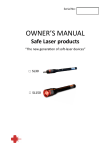
The basic 501A-type DSU, shown in Fig. 1
with DAS 821A-L1, consists of a transmitter,
receiver, control logic, and customer interface
circuits mounted on two circu it packs (C P s)
interconnected by a flexible cable harness. If t he
optional ACI is provided, the DSU will contain three
CPs . The CPs are contained in a basic housing
similar to that of the 208A-type data set. This
2.01
housing consists of front and rear molded black
plastic faceplates mounted on an extruded aluminum
frame.
The 501A-type DSU is approximatel y 16
inches wide, 11.4 inches deep, 4.3 inches
high, and weighs 17.3 pounds.
2.02
The DSU will operate in an environment of
40 to 120·F, with a relative humidity of less
than 95 percent.
2.03
Power requirements for the self-contained
83A power unit are 105 to 129 Vac at 57
to 63 Hz. • The KS-14532, L24 unshielded power
cord, six feet in length, is provided with the DSU.
A shielded 3-conductor ac power cord (P3BJ), 5.5
feet in length, may be used in an electrically noisy
environment .•
2.04
An assembly containing a 3-position slide
switch and four light-emitting diode (LED)
indicators (designated as PWR, NS, LL, and RT)
is provided. The DSU is furnished with the assembly
mounted at the front. However, the assembly may
be optionally mounted at either the front or rear,
as required.
2.05
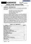
The 501A-type DSUs are equipped with one
logic board CP and one analog board CP
and, optionally, an ACI CP as shown in Fig. 2.
LD3 CP performs the DSU logic functions and is
common to all the DSUs . LD1 (9 .6 kb / s) and
LD2 (56 kb / s) are the analog boards and they
2.06
Fig. 1_.501A-L1/3 /4 DSU and DAS 821A- Ll Type.
Page 2
ISS 2, SECTION 595-300-100
determine the DSU service bit rate. An optional
LD4 CP provides automatic call originating capability
for CPE equipped to originate SDDS calls and also
provides interface for 821A-type DASs to manually
answer and originate calls. Table A lists DSU
service bit rates and CPs.
All customer options are selected with the
switches on LD1 (9.6 kb/s) or LD2 (56 kb/s)
CPs with the exception of the ACI call termination
options. These options are selected with the screw
switch located on LD4 CP.
2.07
All customer data interface leads of a DSU
operating at 9.6 kb/s •and the ACI leads
of both the 9.6- and 56-kb/s DSUs• are terminated
in a 25-pin connector. CPE used with this DSU
must be terminated in a Cinch or Cannon DB-19604-432
•or AMP 205784-1, or equivalent,. plug and a
Cinch· DB-51226-1 hood, or equivalent. A DSU
operating at 56 kb/s uses a 34-pin connector for
the data interface leads. CPE used with a 56-kb/ s
DSU must be terminated in a Winchester
.MRA-34P-JTC6-H8, Burndy MS 34PM-124, AMP
5-202431-2, or• equivalent. Refer to Fig. 3 for
customer interface location.
consists of transmit logic and line driver circuitry,
which accepts digital data from the interface logic
in the form of unipolar voltages and transmits
balanced, •modified• bipolar signals over the local
loop transmit pair (T1, R1). Customer data is
encoded by the transmit logic into a format suitable
for transmission. Since a long sequence of zeros
does not provide transitions to maintain timing
recovery, sequences of six or seven consecutive
zeros in the data stream, depending on service bit
rate (9.6 or 56 kb/s), are replaced with zero
suppression codes (bipolar violation code) to maintain
synchronization.
2.08
3.
FUNCTIONAL DESCRIPTION
This part contains a brief functional description
of the transmitter, receiver, and customer
interface circuits. The interface leads are described
and functional descriptions of the DSU options are
provided.
3.01
The 501A-type DSU provides for duplex
digital transmission and reception of data,
in modified bipolar format, over 4-wire local
transmission facilities. In normal bipolar format,
a binary 0 is transmitted as zero volts and a binary
1 is transmitted as either a positive or negative
pulse which is opposite in polarity to the previous
binary 1. The SDDS modifies this format such
that network control codes incorporate bipolar
violations where two successive pulses (1s) have
the same polarity. To avoid de buildup on the
line, each bipolar violation has a polarity opposite
to that of the previous violation, thus making the
sum of the signal voltages equal to zero.
3.02
A.
3.03
TransmiHer
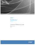
Refer to Fig. 4 for a functional block diagram
of the 501A-type DSU. The transmitter
The line driver converts the binary outputs
of the transmit logic into a balanced,
•modified• bipolar signal. The line driver also
contains a low-pass filter that prevents the
transmission of unnecessary high-frequency energy
over the channel. The bipolar signal is then
transformer-coupled to the cable pair.
3.04
B.
Receiver
The receiver consists of receive logic, clock
recovery, and a line receiver. The line
receiver may be subdivided into an analog-to-digital
(A/D) converter and automatic gain control (AGC)
associated with automatic line buildout (ALBO)
circuitry. The receiver functions will be discussed
in reverse order to simulate signal flow.
3.05
Since local cable pairs may vary in length
and gauge, an ALBO network is provided
to compensate for these variations. The ALBO
network automatically inserts attenuation, which
varies with frequency, in order to make the net
transmission loss simulate a maximum length of
local cable pairs. Because the range of adjustment
provided by the ALBO network is limited, a 10dB fixed line buildout (FLBO) network, which is
selectable (in or out), is needed to insert additional
loss in the case of extremely short local cable pairs.
3.06
The AGC provides gain and frequency
compensation to equalize the cable loss
characteristics of a maximum length cable pair.
The combination of AGC and line buildout network
provides equalization for a cable loss characteristic
which is the average of the loss characteristics of
standard cable pair gauges (19 through 26 gauge).
3.07
Page 3
SECTION 595-300-100
ACI BOARD
{LD4 CP)
LED ASSEMBLY
LOGIC BOARD
{LD3 CP)
Fig. 24501A-Ty pe DSU-Front Internal View.
TABLE A
DSU SERVICE BIT RATE AND CIRCUIT PACKS
DSU LIST
501A-Ll/2
501A-Ll/3
501A-Ll/2 /4
501A-Ll/3 /4
DSU SERVICE
BIT RATE
9.6 kb/s
ANALOG
CP
LDl
kb/s
LD2
9.6 kb/s
LDl
56
56
kb/s
LD2
LOGIC
CP
ACU
CP
t
LD3
!
LD4
LD4
3.08
The AID converter slices the signal to
produce a binary representa tion of the
received • modified• bipolar signal.
the oscillator to the received timing signal. Thus,
a sampling clock is derived from the received bipolar
signal and is used to sample the data pulses.
The clock recovery circuitry consists of a
voltage-con trolled oscillator connected in a
phase-locked loop. A phase comparator synchronize s
3.10
3.09
Page 4
In the receive logic circuitry, the data stream
is sampled, converted to the unipolar format,
and the data bits reconstruct ed to fully occupy
ISS 2, SECTION 595-300-100
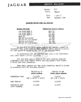
CUSTOMER
DATA
INTERFACE
CONNECTOR
\
DAS 821A- Ll
CONNECTOR
Fig.
~SOlA-Type
S2
S4 1
CUSTOMER OPTION
SWITCHES
DSU-Rear Internal View.
each respective time slot. The data stream then
passes through a violation detector to recognize
bipolar violation sequences (various control codes
and the zero suppression code). When a bipolar
violation sequence occurs, the data stream is
examined for the presence of a valid control code
by the receive logic. After the detection of •eigh~
consecutive control codes, the appropriate control
state is entered. Control states occur as part of
the SDDS call setup and maintenance activity.
The receiver output logic passes data, monitors
violations, and, upon detection of violation,
provides control signals to the control interface.
Upon direction from either the 821A-type
DAS or the ACI, the call originate sender
signals the transmit logic to go off- or on-hook.
The call originate sender contains logic circuitry to
convert the BCD address digits to the ASCII code
which is used for SDDS signaling.
3.13
The display logic provides logic functions
and drivers to control the 7-segment displays
and single LED displays on the 821A-type DAS.
3.14
3.11
D.
Customer Data Interface Circuits (Data Interchange
Interface)
The 501A-L1/2 DSU is provided with 14
interface leads, while the 501A-L1/3 DSU
has 18 interface leads for connection to the CPE.
These leads and their corresponding pin numbers
are given in Table B. Descriptions of the EIA
interface leads are given below with the EIA
designation for each lead appearing in parentheses
with the exception of the IS and LL leads.
Additionally, a description of the IS and LL interface
lead functions, unassigned by EIA Standard RS-232,
is given.
3.15
C.
ACI and DAS Control Circuits (Optional)
The optional ACI and DAS control circuits
consist of the ACI, call originate sender,
and the display logic. Called party address digits
are presented by the CPE to the ACI circuits in
binary coded decimal (BCD) form. The least
significant digit is set on NB1, the next in significance
is set on NB2, the next on NB4, and the most
significant on NB8.
3.12
Page 5
"'g
i
m
'l
"'•
Oo
REMOTE TERMINAL (RT)
OR DSU LOOPBACK
--- cp- , r-- cp u;3- - ,I r-I
r-PAR Tor
LD I OR LD2
I
PARror cPLDI oR LD2
I I
"' Jl
----~lllh
T
I
>-+I
I
I
>-+I
'{I
I
i : :: J~::;:'
*
I
I
CUSTOMER
DATA
TERMINAL
EQUIPMENT
Ul
...,
I
>-t
>i
)-t
I
)-t
I
I
I
)-t
I
I
I
+
I
1-;;;LD4- - - ,..,. J4
I
) I
I
) I
4
4
PWI
1
1
DLO
1
I
cos I
ACR
I
PND
I
CUSTOMER
)-t
AUTOMATIC
CALL
I
ORIGINATING
)4
EQUIPMENT
DPR
)-1
r
1
I
~
I
NB2
I
~
~I
N84 I
I
>-i
1
CRQ
AB
T
AA
CUSTOMER
INTERfACE
CONNECTORS
CALL
ORIGINATE
SENDER
I
ACI
INTERFACE
DISPLAY
LOGIC
821A•TYPE
OAS
CONTROLLER
I
1
NBI
NBS
l== j
TO LOCAL
CABLE PAIRS
1..-J I
I
I
_1..--J I
I
I
I
I
I
I
-12
+12
POWER
SUPPLY
+5
117 VAC
SIG GRD
F"R GRD
I
L--------------~
a DAS 821A-L1 Type.
fig. 4--tfiJinctlonal Block Diagram of a 501A-Type DSU and
-,.
~
g
ISS 2, SECTION 595-300-100
.TABLE B.
501A-TYPE DSU DATA INTERFACE
EIA
PIN
NO.
EIA
STD
DESIG
CCITT
CONN
TERM.
CCITT
STD
DESIG
DSU LEAD
9.6-k b/s
MNEMONIC
56-k b/s
MNEMONIC
A
AA
Frame Ground
FG
FG
p
s
BA(A)
BA(B)
Send Data
Send Data
SD
SD(A)
SD(B)
BB
R
T
BB(A)
BB(B)
Receive Data
Receive Data
RD
RD(A)
RD(B)
4
CA
c
CA
Request-to-Send
RS
RS
5
CB
D
CB
Clear-to-Send
cs
cs
6
cc
E
cc
Data Set Ready
DSR
DSR
7
AB
B
AB
Signal Ground
SG
SG
8
CF
F
CF
Received Line Signal Detector
RLSD
RLSD
11
Uasgn
K
Uasgn
Local Line
LL
LL
15
DB
y
AA*
DB( A)
DB( B)
Serial-Clock-Trans mit
Serial-Clock-Trans mit
SCT
SCT(A)
SCT(B)
17
DD
v
X
DD(A)
DD(B)
Serial-Clock-Receive
Serial-Clock-Receive
SCR
SCR(A)
SCR(B)
20
CD
H
CD
Data-Terminal-Rea dy
DTR
DTR
22
CE
J
CE
Ring Indicator
RI
RI
')!;
T SIRfJ'!l
NN** Uasm
In-Service
IS
IS
1
AA
2
BA
3
*
Designated "a" on Winchester connector.
**
Designated "n" on Winchester connector.
Frame Ground (AA)-Pin 1: This lead is
connected to the DSU housing and the local
power ground through the third conductor in the
power cord. It is connected to signal ground
through the power cord as explained in 3.22.
3.16
Send Data (BA)-Pin 2: The direction of
signal flow on this lead is from the CPE to
the DSU. The serial, binary data bits on this lead
are generated by the CPE for transmission to the
remote CPE. Data bits are transmitted only if
the following interface lead conditions are met:
CC is on, CA is on, CB is on, and CD is on.
For the 501A-Ll/2 DSU, BA meets the requirements
of an EIA interface, while the 501A-Ll/3 DSU
requires a direct-coupled signal sent over the BA(A)
and BA(B) leads.
3.17
Receive Data (BB)-Pin 3: The direction
of signal flow on this lead is from the DSU
to the CPE. Signals on this lead are generated
by the receiving DSU in response to the data
3.18
Page 1
SECTION 595-300-100
stream received from the distant DSU. The CPE
should sample BB on the negative transitions of
DD. The BB interface lead will be held in the
mark-hold state (steady ls} when control signal CF
is off. For the 501A-Ll/2 DSU, BB meets the
requirements of an EIA interface, while the 501A-Ll/3
DSU provides a direct-coupled signal given serially
on the BB(A) and BB(B) leads.
Request-to-Send (CA)-Pin 4: The direction
of signal flow on this lead is from the CPE
to the DSU. Signals on this lead are generated
by the CPE to turn the local data transmitter on
when the switched carrier option is used. The CA
lead must be held on whenever the CPE has data
ready for transmission. An off condition on the
CA lead causes the DSU to transmit steady marks
if Option XA is installed, or the DSU will transmit
a control code [data mode extension (DME) character]
if Option XB is installed. An on condition on the
CC lead is required for the above conditions. For
DSUs using the continuous request-to-send option,
the DSU transmits continuously, regardless of the
status of the CA lead.
3.19
Clear-to-Send (CB)-Pin 5: The direction
of signal flow on this lead is from the DSU
to the CPE. Signals on this lead are generated
by the DSU to indicate to the CPE readiness to
transmit data. In response to an on condition of
CA and CD from the CPE, the DSU will complete
the handshaking sequence with the distant-end
DSU, then enter the data mode. There is no delay
before the DSU enters the data mode if Option
XA (continuous carrier) is installed. There is a
3-byte delay if Option XB (switched carrier) is
installed. If the DSU is equipped with Option YT
(switched request-to-send), CB turns off when CA
is turned off.
3.20
The 501A-type DSU provides this connection as a
customer option.
Received Line Signal Detector (CF)-Pin
8: The direction of signal flow on this lead
is from the DSU to the CPE. Signals on this lead
are generated by the local DSU and indicate that
data is being received and has been received for
an 8-byte interval. The CF is turned off when
no data signal is received. When the CF lead is
off, the BA lead is held in the mark-hold (binary
1) condition.
3.23
Serial-Clock-Tran smit (DB)-Pin 15: The
direction of signal flow on this lead is from
the DSU to the CPE. Signals on this lead provide
the CPE with transmit signal element timing. For
4.8- and 9.6-kb/s services, DB meets the requirements
of an EIA-type interface, while 56-kb/s service
utilizes a balanced direct-coupled signal sent over
the DB(A) and DB(B) leads. DB is identical to DD.
3.24
Serial-Clock-Rec eive (DD)-Pin 17: The
direction of signal flow on this lead is from
the DSU to the CPE. Signals on this lead provide
the CPE with receive signal element timing. For
4.8- and 9.6-kb/s services, DD meets the requirements
of an EIA-type interface, while 56-kb/s service
utilizes a balanced direct-coupled signal sent over
the DD(A) and ·DD(B) leads.
3.25
In-Service (IS)-Pin 25: The direction of
signal flow on this lead is from the CPE to
the DSU. When the DSU is in the automatic mode,
an oH condition on the IS lead places the DSU in
the not-ready mode while the DSU is on-hook.
Optional control of the IS lead is provided by
Options XQ and XR.
3.26
Data-Terminal-R eady (CD)-Pin 20: The
direction of signal flow on this lead is from
the CPE to the DSU. When the DSU is in the
automatic mode, an on condition of the CD lead
simultaneous with a ringing signal on RI causes
the DSU to answer the incoming call. CD can be
held continuously on by the CPE in preparation
for answering an incoming call. If the CPE turns
CD off while an established call is in progress,
the DSU will go on-hook, thus terminating the call.
3.27
Data-Set-Ready (CC)-Pin 6: The direction
of signal flow on this lead is from the DSU
to the CPE. An on signal on this lead indicates
that the DSU is connected to an SDDS channel,
call originating or call answering functions have
been completed, and the DSU is not in a test mode
(RT or LL).
3.21
Signal Ground (AB)-Pin 7: This lead
establishes the common ground reference
potential for all interface leads. Signal ground is
normally connected to frame ground to minimize
introduction of noise into the electronic circuitry.
3.22
Page 8
Ring Indicator (CE)-Pin 22: The direction
of signal flow on this lead is from the DSU
to the CPE. An incoming call causes a ringing
signal to appear on this lead. The repetitive signal
3.28
ISS 2, SECTION 595-300-100
consists of approximately 1-second ringing followed
by a 3-second off interval.
3.31
Local Line (LL) Pin 11: The direction of
signal flow on this lead is from the CPE to
the DSU. When the DSU is in the automatic mode,
an on condition on this lead places the DSU in LL
loopback mode.
3.29
ACI Circuits (Optional)
E.
The optional ACI (LD4 CP) provides 13
interface leads for connection to
customer-provided, automatic call originating
equipment. These leads and their corresponding
pin numbers are given in Table C. All ACI leads
conform to EIA Standard RS-366 as described below,
with the EIA designation for each lead appearing
in parentheses.
3.30
3.32
Digit Present (DPR)-Pin 2: The direction
of signal flow on this lead is from the CPE
to the DSU. The on condition of this lead indicates
that a called party address digit is on interface
leads NB1, NB2, NB4, and NBS. PND must be
in the on condition before DPR is turned on, and
DPR must then be held on until PND is turned
of£ When PND is off, DPR must also be off to
permit the CPE to set the next address digit on
the digit signal circuits. DPR must be held off
after the last address digit has been transmitted.
3.33
Abandon Call and Retry (ACR)-Pin 3:
1
AA
Frame Ground
2
DPR
Digit Present
3.34
3
ACR
Abandon Call and Retry
4
CRQ
Call Request
5
PND
Present Next Digit
6
PWI
Power Indication
7
AB
Signal Ground
13
cos
Call Origination Status
14
NBl
Digit Signal Circuit
15
NB2
Digit Signal Circuit
16
NB4
Digit Signal Circuit
17
NBS
Digit Signal Circuit
direction of signal flow on this lead is from
the DSU to the CPE. An on condition of the
PND lead indicates that the DSU is ready to accept
the next address digit on the digit signal circuits
from the CPE. The PND lead is held on until
DPR is turned on and the next address digit is
registered, then PND is turned off. The DSU
must 'turn PND on following the last address digit.
22
DW
Data Line Occupied
3.36
AUTOMATIC CALLING INTERFACE
EIAPIN
NUMBER
l
'
connected to the DSU housing and the local
power ground through the third conductor in the
power cord.
The direction of signal flow on this lead is
from the DSU to the CPE. An on condition of
this lead indicates that connection to a remote
DSU is unlikely to be established. The CPE must
turn CRQ off when the ACR lead turns on. A
default timer starts when CRQ is turned on and
resets each time PND turns off, or a remote ring
call progress signal is received. If the timer is
not reset within 12 seconds, the ACR lead turns
on. Upon connection to a remote station, the
ACR lead is not turned on by the timer.
TABLE C
I
Frame Ground (AA)-Pin 1: This lead is
EIASTD
OESIG
ACI LEAD
I
Call Request (CRQ)-Pin 4: The. direction
of signal flow on this lead is from the CPE
to the DSU. If PWI is on and DLO is off, the
CPE may turn CRQ on to originate a call attempt.
CRQ must then remain on during call origination
until COS turns on. The CPE may turn CRQ off
after COS turns on without causing disconnect,
unless Option XO is installed. CRQ must be turned
off after a call is terminated and before the next
call is initiated.
3.35
Present Next Digit (PND)-Pin 5: The
The
direction of signal flow on this lead is from
the DSU to the CPE. An on condition of the
Power Indication (PWI)-Pin 6:
Page 9
SECTION 595-300- 100
PWI lead indicates that ac power is applied to the
DSU.
Signal Ground (AB)-P in 7: This lead
establis hes the common ground referenc e
potential for all interface leads. Signal ground is
normally connecte d to frame ground to minimize
introduction of noise into the electronic circuitry.
3.37
Call Origina tion Status (COS)- Pin 13:
The direction of signal flow on this lead is
from the DSU to the CPE. An on condition of
this lead indicates that the ACI has completed the
call originati on sequenc e and that control of the
data channel has been transfer red to the data
intercha nge interface.
3.38
separate ly looped toward both the SCO and the
custome r interfac e (see Fig. 4). Loopbac k tests
may be perform ed by the STC or from the CPE
location when the CHAN loopbac k function is
perform ed as described in 3.41. When the switch
is position ed to RT (remote termina l loopback ),
interface leads BA and BB are connected together
and disconnected from the CPE. Remote terminal
loopback may also be activated remotely from the
STC by transmi tting a control code sequenc e
containi ng bipolar violation s. Remote termina l
loopback is called DSU loopback when originate d
by the STC. The switch is placed in the center
position for normal operation (data mode).
• PWR-Il luminat es when ac power is supplied
to the DSU and + 5 Vde is available.
Digit Signal Circui t (NB1) -Pin 14,
(NB2) -Pin 15, (NB4) -Pin 16, and
(NB8)- Pin 17: The direction of signal flow on
these leads is from the CPE to the DSU. Parallel
binary-c oded digits are set on these leads for
addressi ng a remote DSU. The CPE must set an
end-of-transmission block (ETB) characte r, and may
optionally set an end-of-number (EON) characte r
to conclude address signaling.
3.39
Data Line Occupie d (DLO)- Pin 22: The
direction of signal flow on this lead is from
the DSU to the CPE. An on condition of this lead
indicates that the DSU is either in manual mode,
test mode, or a call is in progress . The DLO lead
must be off prior to initiating a call attempt using
the ACI.
The LED assembly indications are as follows.
3.43
• NS-Illu minates when no signal is received
over the local transmission facilities.
• LL-Illum inates when the DSU is switched
to the local line (LL) loopbac k mode or
when the CHAN loopback code is detected
by the simplex current detector.
3.40
F.
Simplex Current Detedor
Reversa l of the local channel simplex current
by the OCU operates a polarity -sensitiv e
relay circuit wired between the center taps of the
transmit and receive transfor mers. Operatio n of
this relay causes a loopback of the local channel
between the line driver and line receiver, and also
connects the transmi t logic to the receive logic.
Function ally, this is the remote CHAN loopback
which is controll ed by the serving test center
(STC).
3.41
G.
Switch and LED Assembl y
A slide switch provides control of the loopback
test functions while the LEDs monitor modes.
When the switch is position ed to LL (local line
loopbac k), the transmi t and receive paths are
3.42
Page 10
• RT-Illu minates when the DSU is switched
to the remote terminal (RT) loopback mode
or when the DSU loopback code is detected
by the control code detection circuitry.
H.
Custome r Options
The 501A-ty pe DSU is provide d with a
number of options which may be requeste d
by the custome r. Custom er options are paired
such that one of each pair must be selected when
the DSU is installed . The features availabl e as
options are listed in Table D and described in the
following paragrap hs. The options are also described
in Reference Guide 590-005 -101-Da ta Service Unit
for Dataphone Switched Digital Service.
3.44
Signal Ground to Frame Ground : With
signal ground connecte d to frame ground
(Option YK), signal ground is internall y connected
to frame ground. The installat ion of this option
depends upon the local noise conditio ns, ground
potentials, and local safety regulations. With signal
ground disconnected from frame ground (Option
YL), the signal ground is isolated from frame
3.45
ISS 2, SECTION 595-300-100
t
TABLE D.
501A-TYPE DSU OPTIONS
OPTION
DEVICE
~
I
I
I
I
I
Switch
Sl
l
I
I
i
I
Switch
S2
I
I
I
Switch
84
I
i
l
Switch and
LED Assembly
li
'j:
OPTION
DESIG
OPTION FEATURE
YK
Signal ground connected to frame ground
YL
Signal ground disconnected from frame
ground
YS
Permanent on request-to-sen d
YT
Terminal controlled request-to-sen d
XQ
Enable not ready
XR
Disable not ready
wv
FLBO network installed
ww
FLBO network removed
XA
Permanent carrier
XB
Terminal controlled carrier
xs
4.8-kb/s data transfer rate
XT
9.6-kb/s data transfer rate
xo
Call termination by CRQ or CD
XP
Call terminated by CD only
XM
Switch and LED assembly torear
XN
Switch and LED assembly to front
ground and the customer must specify an alternate
means of grounding.
Request-to-Se nd Operation: With continuous
request-to-send (Option YS), the DSU operates
as if the CA lead is constantly on. This option is
used with CPE which is not capable of switching
the CA interface lead. With switched request-to-send
(Option YT), the CPE must be capable of switching
the CA lead. This option (YT), along with the XB
Option, is necessary for half-duplex operation.
CIRCUIT
PACK
LDl
or
LD2
LDl
or
LD2
LDl
LD4
LDl
or
LD2
'
Control: After connection to a
Carrier
remote DSU has been established, the
following events occur:
3.47
3.46
(a) With continuous carrier (Option XA)
(1) When the CPE turns off the CA lead,
the CB lead turns oJ:Tand the DSU transmits
steady marks.
Page 11
SECTION 595-300-100
(2) When the CPE turns on the CA lead,
the CB lead turns on and the DSU transmits
data present on the BA lead.
(b) With switched carrier (Option XB) (needed
for half-duplex operation)
(1) When the CPE turns off the CA lead,
the CB lead turns oHand the DSU transmits
a continuous stream of DME characters. DME
characters cause the remote DSU to turn oH
the CF interface lead.
(2) When the CPE turns on the CA lead,
the CB lead turns on after a delay of 3
bytes to permit the remote DSU to tum on
the CF lead. After CB has turned on, the
DSU can transmit data present on the BA
lead.
Loopback Switch and LED Assembly
Position: This physical option determines
the location of the loopback switch and LED
assembly. With Option XM, the assembly is located
at the rear of the DSU. With Option XN, the
assembly is located at the front of the DSU.
3.51
I.
FLBO Network: For DSU installations
where the local loop may be too short for
proper operation of the line receiver, an FLBO
network is optionally provided to insert additional
attenuation. With Option WV, the FLBO is
installed. With Option WW, the FLBO is removed.
Refer to the section entitled Digital Data System-Local
Loops-Engineerin g Guidelines (880-601-115) for
criteria to determine use of this option.
3.52
4.
3.48 Call Termination With CRQ: With call
termination via CRQ after COS goes on
(Option XO), calls that are originated using the
. ACI are terminated by turning CRQ or CD off.
Both CD and CRQ must be held on after COS
turns on to maintain the call-on state. With call
not terminated via CRQ after COS goes on (Option
XP), CRQ can be turned oH after COS turns on
without terminating the call. The CI)c lead must
remain on to prevent terminating the call.
Control of Not-Ready Condition by CPE:
With enable not ready (Option XQ), the IS
interface lead is controlled by the CPE. If the
CPE turns on the IS lead, when the DSU is in
the call-off mode, the DSU will transmit repeated
idle control sequence codes to the OCU. If the
CPE turns off the IS lead when the DSU is in
the call-off mode, the DSU will transmit repeated
not-ready control codes to the OCU. With disable
not ready (Option XR), the DSU functions as if
the IS lead were continuously on. The DSU
transmits repeated idle control sequence codes to
the OCU when the DSU is in the call-off mode.
Telco Option
OPERATION
This part contains information concerning
the manual operation of the 501A-type DSU
and the DAS 821A-Ll.
4.01
A.
SOlA-Type DSU Operation
Attendant operation of the DSU is limited
to the slide switch and observation of the
LED indications as follows.
4.02
• For local line loopback, position the slide
switch to LL and observe illumination of
the respective LED.
3.49
• For remote loopback, position the slide switch
to RT and observe illumination of the
respective LED.
• At completion of loopback tests, restore the
slide switch to center position.
B.
DAS 821A-L1 Operation
The DAS 821A-Ll is available on an optional
basis to provide a means of manually
originating, answering, and terminating SDDS calls.
In addition, call progress indications and limited
test features are provided by the DAS 821A-Ll.
4.03
4.8-kb/s Interface Using a 9.6-kb/s
Channel: This option is available only on
the 501A-L1/2 or 501A-Ll/2/4 DSU. With the 4.8kb/s data transfer rate (Option XS), a 4.8-kHz
clock signal is provided on DB and DD interface
leads. With the 9.6-kb/s data transfer rate
(Option XT), the DSU functions as described
throughout this section.
3.50
Page 12
If a call is originated or answered
manually, the operator must depress
the MM switch which will extinguish
the MM indicator before data can be
ISS 2, SECTION 595-300-100
In order for the CPE to answer
automatically, the MM LED must be
extinguished.
transferred through the data exchange
interface.
Manual Call Originating
Depressing the CALL switch on the DAS
while in either the manual or automatic
mode initiates a call request and illuminates the
CALL LED. The DSU enters the off-hook mode
and transmits synchronization characters to the
SCO. In response to "dial tone" from the SCO,
the PROCEED LED illuminates. A 7-digit address
of the station being called, followed by an ETB
character (# on the dial pad), can then be entered
on the DAS 821A-Ll dial pad.
4.04
4.05
Manual Call Termination
Calls can be terminated while the data station
is in manual mode (MM) by depressing either
the CALL or NR (not-ready) switch. Depressing
the CALL switch extinguishes the CALL LED and
permits the data station to accept subsequent calls.
If the call is terminated by depressing the NR
switch, the CALL LED also extinguishes but the
data station enters the not-ready mode which blocks
all incoming calls.
4.08
If the station address is accepted by the
central office switching equipment, the
PROCEED LED extinguishes. If the call is
established, the REMOTE RING LED illuminates
until the call is answered by the remote DSU. If
the call cannot be established, the RECALL LED
illuminates and the DAS displays a 2-digit call
progress code as follows:
Not-Ready Mode
4.09
• Depressing the NR switch when the data
station is in manual mode
DEFINITION
CODE
10
Station Busy
11
Station Not Ready
20
Time-Out
21
Trunk Busy
30
Invalid
The not-ready mode can be entered by either
of two means:
• CPE turns off the IS interface lead when
the data station is in automatic mode.
Either action causes the data station to block all
incoming calls. Any station which attempts to
originate a call to a remote station that is in the
not-ready mode receives a not-ready call progress
code. The data station can be returned to the
normal operating condition by again depressing
the NR switch or by the CPE turning on the IS
lead (reverse procedure for entering not-ready
mode).
The appropriate action to the received code must
be taken in order to complete the call.
5.
To attempt a subsequent call, the CALL
switch must be depressed to clear the central
office switching equipment and extinguish the
RECALL LED. Depressing the CALL switch for
the second time initiates a new call request.
REFERENCES
4.06
The following BSPs contain additional
information pertaining to the 501A-type DSU
and DAS 821A-L1:
5.01
SECTION
TITLE
Manual Call Answering
When the data station is in manual mode,
an incoming call causes the audible ringer
to sound and the CALL LED to flash. The incoming
call can then be answered by depressing the CALL
switch. A valid connection is indicated by the
illumination of the CONNECT LED.
590-005-101
Data Service Unit For Dataphone
Switched Digital Service-Reference
Guide
595-300-180
Switched Digital Data System501A-Type Data Service Unit
-Summarizing Specification
4.07
Page 13
SECTION 595-300-100
SECTION
TITLE
TITLE
598-085-100
Switched Digital Data System-Data
Auxiliary Set 821A-Type Identification
Switched Digital Data System501A-Type Data Service Unit
-Maintenance
880-601-115
Digital Data System-Lo cal
Loop-Enginee ring Guidelines
Switched Digital Data System501A-Type Data Service Unit
-Test Procedures
5.02
595-300-200
Switched Digital Data System501A-Type Data Service Unit
-Installation and Connections
595-300-300
595-300-500
Page 14
14 Pages
SECTION
Detailed information concerning the 501A-type
DSU is contained in CD- and SD-1D253-0l.