1
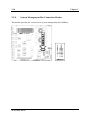
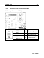
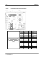
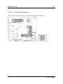
SI-2Ns44X Series Dual Xeon Server Board Socket 604 User’s Manual Rev. 1.00 Copyright and Warranty Notice The information in this document is subject to change without notice and does not represent a commitment on part of the vendor, who assumes no liability or responsibility for any errors that may appear in this manual. No warranty or representation, either expressed or implied, is made with respect to the quality, accuracy or fitness for any particular part of this document. In no event shall the manufacturer be liable for direct, indirect, special, incidental or consequential damages arising from any defect or error in this manual or product. Product names appearing in this manual are for identification purpose only and trademarks and product names or brand names appearing in this document are property of their respective owners. This document contains materials protected under International Copyright Laws. All rights reserved. No part of this manual may be reproduced, transmitted or transcribed without the expressed written permission of the manufacturer and authors of this manual. SI-2Ns44X Series Table of Contents Chapter 1. 1.1. 1.2. 1.3. Chapter 2. 2.1. 2.2. 2.3. Chapter 3. 3.1. 3.2. Introduction .................................................... 1-1 Features & Specifications....................................................... 1-1 Layout Diagram...................................................................... 1-3 Jumpers & Connectors Description........................................ 1-4 Hardware Setup.............................................. 2-1 CPU Socket ............................................................................ 2-1 System Memory ..................................................................... 2-2 Connectors, Headers, and Switches ....................................... 2-3 2.3.1. EPS Power Connectors ............................................. 2-3 2.3.2. FAN Connectors ....................................................... 2-4 2.3.3. CMOS Memory Clearing Header............................. 2-5 2.3.4. Front Panel Switches & Indicators Connection Headers ..................................................................... 2-6 2.3.5. PCI Slot..................................................................... 2-7 2.3.6. Additional USB Port Connection Header................. 2-8 2.3.7. IDE Disk Drive Connector ....................................... 2-9 2.3.8. System Management Bus Connection Header ....... 2-10 2.3.9. Additional COM Port Connection Header ............. 2-11 2.3.10. Connection Header for Parallel Port....................... 2-12 2.3.11. Serial ATA connectors ........................................... 2-13 2.3.12. Low Pin Count Connection Header........................ 2-14 2.3.13. LED Connector for Network Interface................... 2-15 2.3.14. External Keyboard/Mouse Connection Header...... 2-16 2.3.15. Connection Header for VGA Output...................... 2-17 2.3.16. External I/O Panel................................................... 2-18 BIOS Setup...................................................... 3-1 Main Menu ............................................................................. 3-2 Advanced Menu ..................................................................... 3-5 3.2.1. Advanced BIOS Features ......................................... 3-5 User’s Manual 3.3. 3.4. 3.5. 3.6. 3.2.2. Advanced Chipset Features ...................................... 3-9 3.2.3. Integrated Peripherals ............................................. 3-10 3.2.4. Power Management Setup ...................................... 3-16 3.2.5. PnP/PCI Configurations.......................................... 3-18 Security Menu ...................................................................... 3-20 PC Health Menu ................................................................... 3-21 Clk/Misc. Menu.................................................................... 3-22 Exit Menu ............................................................................. 3-24 Chapter 4. Driver Installation .......................................... 4-1 Appendix A. How to Get Technical Support ..................... A-1 SI-2Ns44X Series Introduction 1-1 Chapter 1. Introduction 1.1. Features & Specifications CPU • Supports dual Intel Xeon (Nocona) FSB 800MHz up to 3.80GHz and higher Chipset • • • Intel Lindenhurst-VS Intel ICH5 2x Intel PXH Networking Security • SI-2Ns441: Onboard one Cavium CN-1120 Security Micro Processor supporting IPSec/SSL (Default) • SI-2Ns442: Onboard two Cavium CN-1120 Security Micro Processors supporting IPSec/SSL (Optional) • SI-2Ns443: Onboard three Cavium CN-1120 Security Micro Processors supporting IPSec/SSL (Optional) VGA • Onboard ATi Rage XL PCI interface VGA (8MB SDRAM) Memory • • • Four 240-pin DIMM sockets Supports 144-bit wide dual channel DDR II 400 memory Up to 16 GB, ECC Registered memory capacity LAN • Intel 82546EB dual-port 64-bit Gigabit Ethernet Controllers x4 System BIOS • • • • Supports Plug-and-Play (PNP) Supports Advanced Configuration Power Interface (ACPI) Write-Protect Anti-Virus function by AWARD BIOS 4MB Flash ROM User’s Manual 1-2 Chapter 1 Expansion Slot • 1x PCI-X 64bit/133MHz (3.3V) Internal I/O Connectors • • • • • • • • • • 1x 44pin IDE connector 2x SATA connectors 1x VGA header 1x COM port header (COM2) 1x USB 2.0 header (Each header support two USB 2.0 devices) 1x LPC debug header 1x Printer port header 1x SM Bus header (For SM Bus and I2C) 1x 50-pin IDE interface Compact Flash Type II socket 1x PS/2 Keyboard/Mouse header (KM1) External I/O Connectors • • • 1x Dual USB 2.0 1x COM port (COM1) LAN Ports: Default: 4x Optical SPF GbE LAN connectors, 4x RJ-45 w/ Transformer and LED single port GbE LAN connectors Optional: [2x Optical + 6x RJ-45] or [8x RJ-45] Miscellaneous • • • • EEB 3.5 form factor (12” x 13”) Hardware monitoring – Including Fan speeds, Voltages, System environment temperature Chassis intrusion detector 3.3V 64-bit riser card supported (Optional) All brand names and trademarks are the property of their respective owners. Specifications and information contained herein are subject to change without notice. SI-2Ns44X Series Introduction 1-3 1.2. Layout Diagram User’s Manual 1-4 Chapter 1 1.3. Jumpers & Connectors Description Jumpers Description Default Setting CCMOS1 CMOS Memory Clearing Header Pins 1-2 Closed (Normal) Connectors Description ATX12V1 8-Pin EPS12V Power Connector ATXPWR1 24-Pin EPS12V Power Connector COM2 Connection Header for Additional COM Port DIMM1~DIMM4 DDR DIMM Slots FAN1/FAN4 CPU and System Fan Power Connectors for CPU1 FAN2/FAN5 CPU and System Fan Power Connectors for CPU2 FAN3 Auxiliary Fan Power Connector FPIO1 Front Panel Switch Connection Headers FP-USB1 Additional USB Port Connection Header IDE1 IDE Disk Drive Connector (Pitch 2.5) J6 Connection Header for Case Intrusion Detector J8/J9 LED Connectors for Network Interface KM1 External Keyboard/Mouse Connection Header LPC1 Connection Header for Low Pin Count (Reserved for internal testing) LPT1 Connection Header for Parallel Port PCI1 PCI-X 64bit/133MHz Expansion Slot (3.3V) SATA1/SATA2 Serial ATA connectors SMBUS1 System Management Bus Header VGA1 Connection Header for VGA Output SI-2Ns44X Series Hardware Setup Chapter 2. 2-1 Hardware Setup 2.1. CPU Socket This server board provides dual 604-pin Zero Insertion Force (ZIF) sockets to install the Intel Xeon CPU. You may install either one or two CPUs, but to set up system with only one CPU, it MUST be installed in the primary socket (socket “CPU1” in this model). To install a second processor, you must verify that the second processor is identical to the first processor with same voltage and speed. Using non-identical processors could cause system failure. User’s Manual 2-2 Chapter 2 2.2. System Memory This server board provides four 240-pin Double Data Rate (DDR) Dual Inline Memory Module (DIMM) slots for Registered ECC DIMM modules with memory expansion size up to 16GB. ATTENTION: Populate the DDR DIMMs in-order and in-pair (of the same type and size) by starting from DIMM1+DIMM2 to DIMM3+DIMM4. DIMM1 X X Single Channel DIMM2 DIMM3 DIMM4 X X X SI-2Ns44X Series X DIMM1 X X Dual Channel DIMM2 DIMM3 X X X DIMM4 X Hardware Setup 2-3 2.3. Connectors, Headers, and Switches All the connectors, headers and switches mentioned here are depending on your system configuration. Some features you may (or may not) have to connect or to configure depending on the peripherals you have connected. WARNING: Always power off the computer and unplug the AC power cord before adding or removing any peripheral or component. Failing to so may cause severe damage to your system board and/or peripherals. Plug in the AC power cord only after you have carefully checked everything. 2.3.1. EPS Power Connectors These two provides the connection to EPS12V power supply. User’s Manual 2-4 2.3.2. Chapter 2 FAN Connectors These connectors each provide power to the cooling fans installed in your system. The CPU must be kept cool by using a powerful fan with heatsink. The system is capable of monitoring the speed of the CPU fan. • FAN1/FAN4: CPU and System Fan Power Connectors for CPU1 • FAN2/FAN5: CPU and System Fan Power Connectors for CPU2 • FAN3: Auxiliary Fan Power Connector WARNING: These fan connectors are not jumpers. DO NOT place jumper caps on these connectors. SI-2Ns44X Series Hardware Setup 2.3.3. 2-5 CMOS Memory Clearing Header This header uses a jumper cap to clear the CMOS memory. • Pin 1-2 shorted (default): Normal operation. • Pin 2-3 shorted: Clear CMOS memory. ATTENTION: Turn the system power off first (including the +5V standby power) before clearing the CMOS memory. Failing to do so may cause your system to work abnormally or malfunction. User’s Manual 2-6 2.3.4. Chapter 2 Front Panel Switches & Indicators Connection Headers This header is used for connecting switches and LED indicators on the chassis front panel. Watch the power LED pin position and orientation. The mark “+” align to the pin in the figure below stands for positive polarity for the LED connection. Please pay attention to connect these headers. A wrong orientation will only cause the LED not lighting, but a wrong connection of the switches could cause system malfunction. • HLED (Pin 1, 3): Connects to the HDD LED cable. • RST (Pin 5, 7): Connects to the Reset Switch cable. • SPKR (Pin 13, 15, 17, 19): Connects to the System Speaker cable. • SLED (Pin 2, 4): Connects to the Suspend LED cable. • PWR (Pin 6, 8): Connects to the Power Switch cable. • C.O. (Pin 14, 16): Connects to Case Open (Intrusion) device. • FLED (Pin 18, 20): Connects to the Fault LED cable. SI-2Ns44X Series Hardware Setup 2.3.5. 2-7 PCI Slot This slot provides one 64bit/133MHz PCI add-on-card connection (3.3V). User’s Manual 2-8 2.3.6. Chapter 2 Additional USB Port Connection Header This header provides two additional USB port connections. Pin 1 3 5 7 SI-2Ns44X Series Signal VCC - Data 0 + Data 0 GND Pin 2 4 6 8 10 Signal VCC - Data 1 + Data 1 GND NC Hardware Setup 2.3.7. 2-9 IDE Disk Drive Connector This connector provides IDE hard drive connection (Pitch 2.5). User’s Manual 2-10 2.3.8. Chapter 2 System Management Bus Connection Header This header provides the connection to system management bus (SMBus). SI-2Ns44X Series Hardware Setup 2.3.9. 2-11 Additional COM Port Connection Header This header provides one external COM2 port connection. Pin Signal DCD (Data Carrier 1 Detect) Pin Signal 2 RXD (Receive-Data) 3 TXD (Transfer-Data) 4 5 GND RTS (Request-to-Send) RI (Ring-Indicator) 6 DTR (Data-Terminal-Ready) DSR (Data-Set-Ready) 8 CTS (Clear-to-Send) 10 VCC (+5V) 7 9 User’s Manual 2-12 2.3.10. Chapter 2 Connection Header for Parallel Port This header provides one external LPT port connection. Pin 1 3 5 7 9 11 13 15 17 19 21 23 25 SI-2Ns44X Series Signal STB# PD0 PD1 PD2 PD3 PD4 PD5 PD6 PD7 ACK# BUSY PE SLCT Pin 2 4 6 8 10 12 14 16 18 20 22 Signal AFD# ERR# INIT# SLIN# GND GND GND GND GND GND GND 26 VCC Hardware Setup 2.3.11. 2-13 Serial ATA connectors These connectors each provide one Serial ATA channel connection. User’s Manual 2-14 2.3.12. Chapter 2 Low Pin Count Connection Header (Reserved for internal testing) SI-2Ns44X Series Hardware Setup 2.3.13. 2-15 LED Connector for Network Interface These headers are reserved for connecting LED indicators of Network Interface J9 Pin 1 3 5 7 9 11 13 15 Signal LAN6_ACT LAN6_100 LAN5_ACT LAN5_100 LAN8_ACT LAN8_100 LAN7_ACT LAN7_100 J8 Pin 2 4 6 8 10 12 14 16 Signal LAN6_Link LAN6_1000 LAN5_Link LAN5_1000 LAN8_Link LAN8_1000 LAN7_Link LAN7_1000 Pin 1 3 5 7 9 11 13 15 Signal LAN1_ACT LAN1_100 LAN2_ACT LAN2_100 LAN3_ACT LAN3_100 LAN4_ACT LAN4_100 Pin 2 4 6 8 10 12 14 16 Signal LAN1_Link LAN1_1000 LAN2_Link LAN2_1000 LAN3_Link LAN3_1000 LAN4_Link LAN4_1000 User’s Manual 2-16 2.3.14. Chapter 2 External Keyboard/Mouse Connection Header This header provides the external connection to keyboard and mouse. Pin 1 3 5 7 9 SI-2Ns44X Series Signal VCC NC KB Data Ground KB Clock Pin 2 4 6 8 10 Signal VCC NC Mouse Data Ground Mouse Clock Hardware Setup 2.3.15. 2-17 Connection Header for VGA Output This header provides one external VGA port connection. Pin 1 3 5 7 9 11 13 15 Signal Red Blue Ground Ground VCC NC H.SYNC DDC Clock Pin 2 4 6 8 10 12 14 Signal Green NC Ground Ground Ground DDC Data V.SYNC User’s Manual 2-18 2.3.16. Chapter 2 External I/O Panel • COM1: Serial port connector • USB1: USB 2.0 connectors • LAN1~LAN4: Optical SPF GbE LAN connectors (Default) • LAN5~LAN8: RJ-45 w/ Transformer and LED single port GbE LAN connectors (Default) SI-2Ns44X Series BIOS Setup Chapter 3. 3-1 BIOS Setup This motherboard provides a programmable EEPROM that you can update the BIOS utility. The BIOS (Basic Input/Output System) is a program that deals with the basic level of communication between processor and peripherals. Use the BIOS Setup program only when installing motherboard, reconfiguring system, or prompted to “Run Setup”. This chapter explains the Setup Utility of BIOS utility. After powering up the system, the BIOS message appears on the screen, the memory count begins, and then the following message appears on the screen: Press DEL to run setup If this message disappears before you respond, restart the system by pressing <Ctrl> + <Alt> + <Del> keys, or by pressing the Reset button on computer chassis. Only when it failed by these two methods can you restart the system by powering it off and then back on. NOTE: In order to increase system stability and performance, our engineering staffs are constantly improving the BIOS menu. The BIOS setup screens and descriptions illustrated in this manual are for your reference only, may not completely match what you see on your screen. After pressing <Del> key, the main menu screen appears. User’s Manual 3-2 Chapter 3 3.1. Main Menu Date (mm:dd:yy) This item sets the date you specify (usually the current date) in the format of [Month], [Date], and [Year]. Time (hh:mm:ss) This item sets the time you specify (usually the current time) in the format of [Hour], [Minute], and [Second]. IDE Channel 1 Master/Slave, Compact Flash (CF1), IDE Channel 2 Slave, IDE Channel 3 Master, IDE Channel 4 Master Move cursor to each of these items, and then press <Enter> key to enter its sub-menu. SI-2Ns44X Series BIOS Setup 3-3 IDE Channel 1 Master/Slave, Compact Flash (CF1), IDE Channel 2 Slave, IDE Channel 3 Master, IDE Channel 4 Master: Click <Enter> key to enter its submenu: IDE HDD Auto-Detection This item allows you to detect the parameters of IDE drives by pressing the <Enter> key. The parameters will automatically be shown on the screen. IDE Channel 1 Master When set to [Auto], the BIOS will automatically check what kind of IDE drive you are using. If you want to define your own drive by yourself, set it to [Manual] and make sure you fully understand the meaning of the parameters. Refer to the manual provided by the device manufacturer to get the settings right. Access Mode This item selects the mode to access your IDE devices. Leave this item to its default [Auto] settings to let BIOS detects the access mode of your HDD and makes decision automatically. Capacity This item automatically displays your HDD size. Note that this size is usually slightly greater than the size given by a disk-checking program of a formatted disk. User’s Manual 3-4 Chapter 3 Cylinder This item configures the numbers of cylinders. Head This item configures the numbers of read/write heads. Precomp This item displays the number of cylinders at which to change the write timing. Landing Zone This item displays the number of cylinders specified as the landing zone for the read/write heads. Sector This item configures the numbers of sectors per track. Back to Main Menu: Halt On This item determines whether the system stops if an error is detected during system boot-up. [All Errors]: The system-boot will stop whenever the BIOS detect a non-fatal error. [No Errors]: The system-boot will not stop for any error detected. [All, But Keyboard]: The system-boot will stop for all errors but keyboard error. Base Memory This item displays the amount of base memory installed in the system. The value of the base memory is typically 640K for system with 640K or more memory size installed on the motherboard. Extended Memory This item displays the amount of extended memory detected during system boot-up. Total Memory This item displays the total memory available in the system. SI-2Ns44X Series BIOS Setup 3-5 3.2. Advanced Menu 3.2.1. Advanced BIOS Features CPU L3 Cache: This item is used to enable the L3 cache (default setting), and appears only for certain CPU (Intel processor with HT Technology Extreme Edition) that possesses L3 cache. User’s Manual 3-6 Chapter 3 Hyper-Threading Technology: This item is used to enable the functionality of the processor with Hyper-Threading Technology and will appear only when using such processor. The Hyper-Threading Technology helps your PC work more efficiently by maximizing processor resources and enabling a single processor to run two separate threads of software simultaneously, bringing forth greater performance and system responsiveness when running multiple applications at once. Quick Power On Self Test When set to [Enabled], this item speeds up the Power On Self Test (POST) after powering on the system. The BIOS shorten or skip some check during the POST. CPU Feature: Click <Enter> key to enter its submenu: Thermal Management This item selects the type of thermal monitoring. Limit CPUID MaxVal When set to [Enabled], this item limits the CPUID maximum value to 3, which is usually required for older OS like Windows NT4.0. Leave this item to its default [Disabled] settings for OS like Windows XP. SI-2Ns44X Series BIOS Setup 3-7 NX BIOS Control When set to [Disabled], this NX features flag will be forced to return to 0. Back to Advanced BIOS Features Setup Menu: Hard Disk Boot Priority: This item selects the hard disks booting priority. By pressing <Enter> key, you can enter its submenu where the hard disks detected can be selected for the booting sequence to boot up system. This item functions only when there is the option of [Hard Disk] in any one of the First/Second/Third Boot Device items. First Boot Device / Second Boot Device / Third Boot Device / Boot Other Device Select the drive to boot first, second and third in the [First Boot Device], [Second Boot Device], and [Third Boot Device] fields respectively. The BIOS will boot the operating system according to the sequence of the drive selected. Set [Boot Other Device] to [Enabled] if you wish to boot from another device other than these three items. Boot Up NumLock Status: This item determines the default state of the numeric keypad at system booting up. [On]: The numeric keypad functions as number keys. [Off]: The numeric keypad functions as arrow keys. Security Option This item determines when the system will prompt for password - every time the system boots or only when enters the BIOS setup. [Setup]: The password is required only when accessing the BIOS Setup. [System]: The password is required each time the computer boots up. NOTE: Don’t forget your password. If you forget the password, you will have to open the computer case and clear all information in the CMOS before you can start up the system. But by doing this, you will have to reset all previously set options. MPS Version Control For OS This item specifies which version of MPS (Multi-Processor Specification) this motherboard will use. Leave this item to its default setting. User’s Manual 3-8 Chapter 3 Delay IDE Initial (Secs): This item allows the BIOS to support some old or special IDE devices by prolonging this delay time. A larger value will give more delay time to the device for which to initialize and to prepare for activation. Remote Access Config: This item enables remote access to system through serial port. Click <Enter> key to enter its submenu: Console Redirection [Enabled]: Attempt to redirect console via COM port. [Disabled]: Attempt to redirect console when keyboard absent. SI-2Ns44X Series BIOS Setup 3.2.2. 3-9 Advanced Chipset Features DRAM Data Integrity Mode This item selects the type of DRAM in your system. ECC is “Error Checking and Correction”. Choose the ECC option only when your memory is ECC type. MCH Compliance Mode This item controls the entry by the MCH into Compliance Mode on all PCI Express ports. Memory RAS Feature This item selects the special feature for DIMM Sparing or Mirroring. User’s Manual 3-10 Chapter 3 Back to Advanced Chipset Features Menu: 3.2.3. Integrated Peripherals OnChip IDE Device: Click <Enter> key to enter its submenu: SI-2Ns44X Series BIOS Setup 3-11 IDE Bus Master This option enables or disables the IDE bus mastering capability under the DOS environment. Onboard IDE-1 Controller This item enables or disables the onboard IDE-1 controller. Onboard IDE-2 Controller This item enables or disables the onboard IDE-2 controller. On-Chip Serial ATA This item determines the function for on-chip Serial ATA. [Disabled]: Disable the Serial ATA controller. [Auto]: Allows the Serial ATA controller to be arranged by BIOS automatically. [Combined Mode]: Parallel ATA and Serial ATA are combined together. Supports up to 4 IDE drives. [Enhanced Mode]: Enable both Parallel ATA and Serial ATA. Supports up to 6 IDE drives. Serial ATA 1 Mode / Serial ATA 2 Mode: This item determines the function mode for SATA1 and SATA 2 Port. Both SATA1 and SATA2 will be served each as one single IDE connector after selected as the following modes: Serial ATA Serial ATA Description Port 1 (SATA1) Port 2 (SATA2) • SATA1 serves as IDE-3 Master • SATA2 serves as IDE-4 Master IDE-3 Master IDE-4 Master • OnChip IDE-1 and IDE-2 controller enabled Enhanced • SATA1 serves as IDE-4 Master • SATA2 serves as IDE-3 Master IDE-4 Master IDE-3 Master • OnChip IDE-1 and IDE-2 controller enabled • SATA1 serves as IDE-1 Master Combined IDE-1 Master IDE-1 Slave • SATA2 serves as IDE-1 Slave • OnChip IDE-1 controller disabled Mode User’s Manual 3-12 Chapter 3 IDE-1 Slave IDE-1 Master IDE-2 Master IDE-2 Slave IDE-2 Slave IDE-2 Master IDE-1 Master IDE-2 Master IDE-2 Master IDE-1 Master SATA Only • • • • • • • • • • • • SATA1 serves as IDE-1 Slave SATA2 serves as IDE-1 Master OnChip IDE-1 controller disabled SATA1 serves as IDE-2 Master SATA2 serves as IDE-2 Slave OnChip IDE-2 controller disabled SATA1 serves as IDE-2 Slave SATA2 serves as IDE-2 Master OnChip IDE-2 controller disabled SATA1 serves as IDE-1 Master SATA2 serves as IDE-2 Master OnChip IDE-1 and IDE-2 controller disabled • SATA1 serves as IDE-2 Master • SATA2 serves as IDE-1 Master • OnChip IDE-1 and IDE-2 controller disabled OnChip PCI Device: Click <Enter> key to enter its submenu: OnChip USB Controller: This option enables or disables the USB controller. SI-2Ns44X Series BIOS Setup 3-13 USB 2.0 Controller: This option enables or disables the USB 2.0 controller. USB Keyboard Support Via: This item allows you to select [BIOS] for using USB keyboard in DOS environment, or [OS] in OS environment. USB Mouse Support Via: This item allows you to select [BIOS] for using USB mouse in DOS environment, or [OS] in OS environment. SuperIO Device: Click <Enter> key to enter its submenu: Onboard Serial Port 1 / Onboard Serial Port 2: This item determines which I/O addresses the onboard Serial Port controller will access. [Auto]: The system automatically select an I/O address for the onboard Serial Port. [3F8/IRQ4, 2F8/IRQ3, 3E8/IRQ4, 2E8/IRQ3]: Allows you to manually select an I/O address for the onboard Serial Port. [Disabled]: Disables the onboard Serial Port. User’s Manual 3-14 Chapter 3 Onboard Parallel Port: This item specifies the I/O address used by the parallel port. [Disabled]: This option prevents the parallel port from accessing any system resources. When the value of this option is set to [Disabled], the printer port becomes unavailable. [378/IRQ7]: This option allows the parallel port to use [378/IRQ7] as its I/O port address. The majority of parallel ports on computer systems use IRQ7 and I/O Port 378H as the standard setting. [278/IRQ5]: This option allows the parallel port to use [278/IRQ5] as its I/O port address. [3BC/IRQ7]: This option allows the parallel port to use [3BC/IRQ7] as its I/O port address. Parallel Port Mode: This item specifies the parallel port mode. [SPP]: (Standard Parallel Port) Allows bi-directional parallel port operation at normal speed. [EPP]: (Enhanced Parallel Port) Allows bi-directional parallel port operation at maximum speed. [ECP]: (Extended Capabilities Port) Allows bi-directional parallel port operation at a speed faster than the normal mode’s data transfer rate. [ECP+EPP]: Allows parallel port operation at ECP and EPP mode. EPP Mode Select: This item selects the EPP mode. ECP Mode Use DMA: This item selects the DMA channel of the parallel port. SI-2Ns44X Series BIOS Setup 3-15 Onboard PCI Device: Click <Enter> key to enter its submenu: Graphic Controller This item enables or disables the onboard graphic controller. CN1120 Controller This item enables or disables the onboard security processor. Network-1/2 Controller This item enables or disables the onboard LAN1/LAN2 Controller. Invoke Boot Agent This item allows you to use the boot ROM (instead of a disk drive) to boot-up the system and access the local area network directly. Network-3/4 Controller This item enables or disables the onboard LAN3/LAN4 Controller. Invoke Boot Agent This item allows you to use the boot ROM (instead of a disk drive) to boot-up the system and access the local area network directly. User’s Manual 3-16 Chapter 3 Network-5/6 Controller This item enables or disables the onboard LAN5/LAN6 Controller. Invoke Boot Agent This item allows you to use the boot ROM (instead of a disk drive) to boot-up the system and access the local area network directly. Network-7/8 Controller This item enables or disables the onboard LAN7/LAN8 Controller. Invoke Boot Agent This item allows you to use the boot ROM (instead of a disk drive) to boot-up the system and access the local area network directly. 3.2.4. Power Management Setup Power Button Function This item selects the method of powering off your system: [Delay 4 Sec.]: Pushing the power button for more than 4 seconds will power off the system. This will prevent the system from powering off in case you accidentally hit or pushed the power button. SI-2Ns44X Series BIOS Setup 3-17 [Instant-Off]: Pressing and then releasing the power button at once will immediately power off the system. CPU THRM-Throttling This item controls the CPU speed by cutting down its regular power to a percentage during the STR (Suspend To RAM) state. Wake-Up by PME# of PCI When set to [Enabled], access to the onboard LAN or a PCI card such as a modem or LAN card will cause the system to wake up. The PCI card must support the wake up function. WakeUp by Alarm When set to [Enabled], you can set the date and time you would like the Soft-Off PC to power-on in the “Date (of Month) Alarm” and “Time (hh:mm:ss) Alarm” items. However, if the system is being accessed by incoming calls or the network (Resume On Ring/LAN) prior to the date and time set in these items, the system will give priority to the incoming calls or network instead. Date (of Month) Alarm [0]: This option power-on the system everyday according to the time set in the “Time (hh:mm:ss) Alarm” item. [1-31]: This option selects a date you would like the system to power-on. The system will power-on on the date set, and the time set in the “Time (hh:mm:ss) Alarm” item. Resume Time (hh:mm:ss) This item sets the time you would like the system to power-on. Restore On AC Power Loss This item selects the system action after an AC power failure. [Power Off]: When power returns after an AC power failure, the system’s power remains off. You must press the Power button to power-on the system. [Power On]: When power returns after an AC power failure, the system’s power will be powered on automatically. [Last State]: When power returns after an AC power failure, the system will return to the state where you left off before power failure occurs. If the system’s power is off when AC power failure occurs, it will remain off when power returns. If the system’s power is on when AC power failure occurs, the system will power-on when power returns. User’s Manual 3-18 3.2.5. Chapter 3 PnP/PCI Configurations Resources Controlled By This item configures all of the boot and Plug-and-Play compatible devices. [Auto]: The system will automatically detect the settings. [Manual]: Choose the specific IRQ resources in the “IRQ Resources” menu. SI-2Ns44X Series BIOS Setup 3-19 IRQ Resources Click <Enter> key to enter its submenu: This item sets each system interrupt to either [PCI Device] or [Reserved]. Maximum Payload Size: This item sets the maximum TLP payload size for the PCI Express devices. User’s Manual 3-20 Chapter 3 3.3. Security Menu Set Supervisor Password This option protects the BIOS configuration or restricts access to the computer itself. The Supervisor Password is used to protect the stored CMOS options from being changed by unauthorized users. Set User Password This option protects the BIOS configuration or restricts access to the computer itself. The User Password requires all users to enter a password in order to use the system, and/or enter the BIOS setup (but can’t change its contents). SI-2Ns44X Series BIOS Setup 3-21 3.4. PC Health Menu FAN Fail Alarm Selectable: This item selects the fan that will be monitored for malfunction. Shutdown When CPUFAN Fail: When set to [Enabled], the system will be shut down if the CPU fan is not running. CPU FanEQ Speed Control: This item allows you to control the CPU fan speed down to a specific percentage. When set to a specific percentage, the CPU fan speed will run at the percentage you set in this item if the temperature limit set in the item “Active Temperature” is not exceeded. The CPU fan speed will run at 100% regardless of what the percentage you set in this item if the temperature limit set in the item “Active Temperature” is exceeded. Active Temperature: This item sets the temperature limit that would activate the function of “CPU FanEQ Speed Control” option. User’s Manual 3-22 Chapter 3 CPU Shutdown Temperature: This item sets the temperature that would shutdown the system automatically in order to prevent system overheats. CPU Warning Temperature: This item selects the CPU’s warning temperature limit. Once the system has detected that the CPU’s temperature exceeded the limit, warning beeps will sound. NOTE: The onboard hardware monitor function is capable of detecting these system health conditions. If you want a warning message to pop-up or a warning alarm to sound when an abnormal condition occurs, you must install the “Hardware Doctor” utility. This utility is included in the “Driver & Utility CD” that came packed with this motherboard. All Voltages, Fans Speed and Thermal Monitoring These unchangeable items list the current status of the CPU and environment temperatures, fan speeds, and system power voltage. NOTE: The hardware monitoring features for temperatures, fans and voltages will occupy the I/O address from 294H to 297H. If you have a network adapter, sound card or other add-on cards that might use those I/O addresses, please adjust your add-on card I/O address to avoid using these addresses. 3.5. Clk/Misc. Menu SI-2Ns44X Series BIOS Setup 3-23 CPU Clock Ratio This option selects the CPU clock ratio. Please type in the correct multiple for your CPU. BIOS Flash Control This option protects the BIOS contents from accidentally writing attempt. NOTE: Make sure to set this item to “Non-Protected” when flashing the BIOS. Case-Open Warning This option controls the function for case-opening detection device connected at pin-7 and pin-8 at FPIO1 header. [Disabled]: Disable the Case-Open Detection. [Enabled]: Enable the Case-Open Detection. [Cleared]: Clear the warning message when the case-opening situation is detected. Warning Beep This option controls the onboard buzzer to beep when the case-opening situation is detected. Watch Dog Function This option controls the function for Watch Dog. [Disabled]: Disable the Watch Dog function. [Enabled/Sec.]: Enable the Watch Dog function by the timer based on seconds. [Enabled/Min.]: Enable the Watch Dog function by the timer based on minutes. Watch Dog Time-Out Value Type in the Time-Out value for your Watch Dog function. User’s Manual 3-24 Chapter 3 3.6. Exit Menu Once you have made all your selections in the previous BIOS setup menu, you have to save the settings and exit the setup menu. Select the Exit Menu in the menu bar to show the following menu: NOTE: Pressing <ESC> does not exit this menu. You have to select one of the options in this menu, such as “Exit Without Saving” to exit the menu without saving your previous settings. Load Fail-Safe Defaults This option loads the BIOS default values for the most stable, minimal-performance system operations. Load Optimized Defaults This option loads the BIOS default values that are factory settings for optimal-performance system operations. Save & Exit Setup This option saves your selections and exits the setup menu. Exit Without Saving This option exits the setup menu without saving any change. SI-2Ns44X Series Driver Installation Chapter 4. 4-1 Driver Installation After all the hardware has been installed, you must first install the operating system and then the software drivers. The necessary drivers are all included within the Drivers & Utilities CD that came packaged with your workstation board. The display shown in the following figure should appear after inserting this CD into your CD-ROM drive, if not, enter [My Computer] CD-ROM drive double click [AUTORUN.EXE]. User’s Manual 4-2 Chapter 4 Setup Items • Drivers Install the drivers for Windows Operating System. • Manual View the user’s manual in PDF file. • Utility Click to enter the sub-screen for installing utilities. • Browse CD Browse the contents of this CD-ROM. • Close Exit the CD setup Items Menu. SI-2Ns44X Series How to Get Technical Support A-1 Appendix A. How to Get Technical Support (From our website) http://www.abit.com.tw (In North America) http://www.abit-usa.com (In Europe) http://www.abit.nl Thank you for choosing ABIT products. ABIT sells all our products through distributors, resellers and system integrators; we have no direct sales to end-users. Before sending email for tech support please check with your resellers or integrators if you need any services, they are the ones who sold you your system and they should know best as to what can be done, how they serve you is a good reference for future purchases. We appreciate every customer and would like to provide the best service to you. Providing fast service to our customers is our top priority. However we receive many phone calls and a huge amount of email from all over the world. At the present time it is impossible for us to respond to every single inquiry. Therefore it is quite possible that if you send an email to us that you may not receive a response. We have done many compatibility tests and reliability tests to make sure our products have the best quality and compatibility. In case you need service or technical support, please understand the constraint we have and always check with the reseller who sold the product to you first. To expedite service, we recommend that you follow the procedures outlined below before contacting us. With your help, we can meet our commitment to provide the best service to the greatest number of ABIT customers: 1. Check the Manual. It sounds simple but we have taken a lot of care in making a well-written and thorough manual. It is full of information that doesn't only pertain to motherboards. The CD-ROM included with your board will have the manual as well as drivers. If you don't have either one, go to our Program Download Area of the Website or FTP server. 2. Download latest BIOS, software or drivers. Please go to our Program Download area on our Website to check to see if you have the latest BIOS. They are developed over periods of time to fixes bugs or incompatibilities. Also please make sure you have the latest drivers from your peripheral cards makers! 3. Check the ABIT Technical Terms Guide and FAQ on our Website. We are trying to expand and make the FAQs more helpful and information rich. Let us know if you have any suggestions. For hot topics check out our HOT FAQ! 4. Internet Newsgroups. They are a great source of information and many people there can offer help. ABIT's Internet News group, alt.comp.periphs.mainboard.abit, is an ideal forum for the public to exchange information and discuss experiences they have had with ABIT products. Many times you will see that your question has already been asked before. This is a public Internet news group and it is reserved for free discussions. Here is a list of some of the more popular ones: User’s Manual A-2 Appendix A alt.comp.periphs.mainboard.abit comp.sys.ibm.pc.hardware.chips alt.comp.hardware.overclocking alt.comp.hardware.homebuilt alt.comp.hardware.pc-homebuilt 5. Ask your reseller. Your ABIT authorized distributor should be able to provide the fastest solution to your technical problem. We sell our products through distributors who sell to resellers and stores. Your reseller should be very familiar with your system configuration and should be able to solve your problem much more efficiently than we could. After all, your reseller regards you as an important customer who may purchase more products and who can urge your friends to buy from him or her as well. They integrated and sold the system to you. They should know best what your system configuration is and your problem. They should have reasonable return or refund policies. How they serve you is also a good reference for your next purchase. 6. Contacting ABIT. If you feel that you need to contact ABIT directly you can send email to the ABIT technical support department. First, please contact the support team for the branch office closest to you. They will be more familiar with local conditions and problems and will have better insight as to which resellers offer what products and services. Due to the huge number of emails coming in every day and other reasons, such as the time required for problem reproduction, we will not be able to reply to every email. Please understand that we are selling through distribution channels and don't have the resources to serve every end-user. However, we will try to do our best to help every customer. Please also remember that for many of our technical support team English is a second language, you will have a better chance of getting a helpful answer if your question can be understood in the first place. Be sure to use very, simple, concise language that clearly states the problem, avoid rambling or flowery language and always list your system components. Here is the contact information for our branch offices: 7. RMA Service. If your system has been working but it just stopped, but you have not installed any new software or hardware recently, it is likely that you have a defective component. Please contact the reseller from whom you bought the product. You should be able to get RMA service there. 8. Reporting Compatibility Problems to ABIT. Because of tremendous number of email messages we receive every day, we are forced to give greater weight to certain types of messages than to others. For this reason, any compatibility problem that is reported to us, giving detailed system configuration information and error symptoms will receive the highest priority. For the other questions, we regret that we may not be able to reply directly. But your questions may be posted to the Internet news group in order that a larger number of users can have the benefit of the information. Please check the news group from time to time. SI-2Ns44X Series How to Get Technical Support North America and South America RMA Center UK and Ireland Germany and Benelux (Belgium, Netherlands, Luxembourg), France, Italy, Spain, Portugal, Greece, Denmark, Norway, Sweden, Finland, and Switzerland Austria, Czech, Romania, Bulgaria, Slovakia, Croatia, Bosnia, Serbia, and Macedonia Shanghai Russia and CIS Poland Japan Taiwan Head Office (Serving all other territories not listed above. Taiwan is 8+ GMT time, and may have different holiday calendar from yours.) A-3 ABIT Computer (U.S.A.) Corporation 45531 Northport Loop West, Fremont CA, 94538, U.S.A. Tel: 1-510-623-0500 Fax: 1-510-623-1092 Sales: [email protected] Latin America Sales: [email protected] Marketing: [email protected] Web Site: http://www.abit-usa.com 46808 Lakeview Blvd. Fremont, CA 94538, U.S.A. ABIT Computer (U.K.) Corporation Ltd. Unit 3, 24-26 Boulton Road, Stevenage, Herts SG1 4QX, UK Tel: 44-1438-228888 Fax: 44-1438-226333 E-mail: [email protected] AMOR Computer B.V. (ABIT's European Office) Jan van Riebeeckweg 15, 5928LG, Venlo, The Netherlands Tel: 31-77-3204428 Fax: 31-77-3204420 Sales: [email protected] Web Site: http://www.abit.nl Asguard Computer Ges.m.b.H Schmalbachstrasse 5, A-2201 Gerasdorf / Wien, Austria Tel: 43-1-7346709 Fax: 43-1-7346713 E-mail: [email protected] ABIT Computer (Shanghai) Co. Ltd. Tel: 86-21-6235-1829 Fax: 86-21-6235-1832 Web Site: http://www.abit.com.cn ABIT Computer (Russia) Co. Ltd. Sales: [email protected] Info: [email protected] Web Site: http://www.abit.ru ABIT Computer (Poland) Co. Ltd. Przedstawicielstwo w Polsce ul. Wita Stwosza 28, 50-149 Wrocław Tel: 48 71 780 78 65 / 66 Fax: 48 71 372 30 87 Web Site: http://www.abit4u.jp ABIT Computer Corporation No. 323, Yang Guang St., Neihu, Taipei, 114, Taiwan Tel: 886-2-8751-8888 Fax: 886-2-8751-3382 Sales: [email protected] Marketing: [email protected] Web Site: http://www.abit.com.tw User’s Manual A-4 Appendix A Technical Support Form Company Name: Phone Number: Contact Person: Fax Number: E-mail Address: Model * Motherboard Model No. DRIVER REV OS/Application * Hardware Name Brand CPU HDD CD-ROM-Drive System Memory ADD-ON CARD Problem Description: SI-2Ns44X Series * IDE1 IDE2 IDE1 IDE2 BIOS ID # Specifications *