1
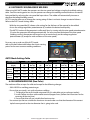
PR-205
SYNERGIC MIG/MAG
WELDER
Instruction Manual
Version 1.0
All Info Copyright © Pro Spot International Inc.
About Pro Spot
Pro Spot International, Inc., based in Carlsbad, California, manufactures resistance spot welding equipment spe-cializing in applications for the collision repair industry. The company began in 1986. The company owns and manages
an on site machine shop, research & development department, a fabrication facility and production lines for the various
welders
Pro Spot International exports its products worldwide, export sales are managed through our headquarter office.
The company owns numerous patents for our ingenious application tools, machines, and procedures.
Pro Spot training and services
Pro Spot Distributors and Sub-Distributors are carefully selected and are well trained in the collision repair industry. We offer
technical and service education at our world wide training facilities at
regular intervals so your local distributor will always be up to date and
able to pass on the latest in spot welding technology to our customers.
Customer service is an important part of any investment and
our distributors and sub-distributors will be there to support your
technical and service needs. We have a great customer service record, we tend to keep it that way.
Pro Spot is certified by CASE and a member of the ICAR Industry Training Alliance
Contact Information
Pro Spot International, Inc. U.S.A.
www.prospot.com
5932 Sea Otter Pl.
Carlsbad, CA 92010
1
Phone: +1 760-407-1414
Toll free (US only): 877- PRO SPOT
Fax: 760-407-1421
E-Mail: [email protected]
All Info Copyright © Pro Spot International Inc.
Table of Contents
1.0 SAFETY INFORMATION
3
1.1 Introduction
1.2 Personal Protection
1.3 Fire Prevention
1.4 Electric Shock
1.5 Noise
1.6 Electromagnetic Compatibility
1.7 Gas Cylinders
3
3
3
4
4
4
4
2.0 INSTALLATION RECOMMENDATIONS
5
2.1 Location
2.2 Ventilation
2.3 Voltage Requirements
2.4 Safety Instructions
5
5
5
6
3.0 INTRODUCTION
6
4.0 PR-205 Basics
7
5.0 STICK WELDING (MMA)
9
5.2 Getting Ready For MMA Welding
6.0 MIG/MAG WELDING
6.1.1 Torch Connection
6.1.2 Installing Welding Wire
6.1.3 Replacing The Wire Liner
6.1.4 How To Choose The Wire Liner
6.1.5 Gas Cylinder And Regulator Connection
6.1.6 MOG Welding (No Gas/Flux Core)
6.1.7 MIG/MAG Welding
6.2 MIG/MAG And No Gas Manual Welding
6.3 Automatic MIG/MAG/MOG Welding
6.4 Aluminum Welding
9
9
9
9
10
10
11
11
11
11
12
12
7.0 PROTECTION GASES GUIDE
13
8.0 WELDING HINTS AND MAINTENANCE
13
9.0 TROUBLESHOOTING
14
NOTES
16
All Info Copyright © Pro Spot International Inc.
2
SAFETY INFORMATION
1.0
1.1INTRODUCTION
Make sure this manual is carefully read and understood by the welder, and by the maintenance personell.
1.2 PERSONAL PROTECTION
Welding processes of any kind can be dangerous not only to the operator but to any person situated near
the equipment, if safety and operating rules are not strictly observed.
Arc rays can injure your eyes and burn your skin. The welding arc produces ultra violet and infra red
light. These arc rays will damage your eyes and burn your skin if you are not properly protected.
• Wear closed, non-flammable protective clothing, without pockets or turned up pants, gloves and
shoes with insulating sole and steel toe. Avoid oily greasy clothing.
• Wear non-flammable welding helmet with appropriate filter lenses designed to shield the neck
and the face, also on the sides. Keep protective lens clean and replace them when broken, cracked or
spattered. Position a transparent glass between lense and welding area.
• Weld in a closed area that is not open to other work areas.
• Never look at the arc without correct protection to the eyes. Wear safety glasses with the side shields
to protect from flying particles.
Gases and fumes produced during the welding process can be dangerous and hazardous to your health.
• Adequate exhaust ventilation must be used in the area. It should be provided through a mobile fume
extractor or through a built-in system on the workbench that provides exhaust ventilation from the
sides, the front and below, but not from above the bench so as to avoid raising dust and fumes. Local
exhaust ventilation must be provided together with adequate general ventilation and air circulation,
particularly when work is done in a confined space.
• Welding process must be performed on metal surfaces thoroughly cleaned from rust or paint, to avoid
production of harmful fumes. Parts degreased with a solvent must be dried before welding.
• Be very careful when welding any metal which may contain one or more of the following:
Antimony Beryllium
Cobalt
Manganese Selenium
Arsenic
Cadmium
Copper
Mercury
Silver
Barium
Chromium
Lead
Nickel
Vanadium
• Remove all Chlorinated solvents from the welding area before welding. Certain chlorinated solvents
decompose when exposed to ultraviolet radiation to form phosgene gas (nerve gas).
1.3 FIRE PREVENTION
Fire and explosion can be caused by hot slag, sparks or the welding arc.
• Keep an approved fire extinguisher of adequate size and type in the welding area. Inspect it regularly
to ensure that it is in proper working order.
• Remove all combustible materials from the working area. If you can not remove them, protect them
with fire-proof covers.
• Ventilate welding areas adequately. Maintain sufficient air flow to prevent accumulation of explosive
or toxic concentrations of gases.
• Do not weld on containers that may have held combustibles.
• Always check welding area to make sure it is free of sparks, slag, or glowing metal and flames.
• The work area must have a fireproof floor.
3
All Info Copyright © Pro Spot International Inc.
SAFETY INFORMATION
1.0
1.4 ELECTRIC SHOCK
WARNING: ELECTRIC SHOCK CAN KILL!
• A person qualified in First Aid should always be present in the working area; If a person is found
unconscious and electric shock is suspected, do not touch the person if she or he is in contact with
cable or electrical wires. Disconnect power from the machine, then use First Aid. Use dry wood or
other insulating materials to move cables away from the person, if necessary.
• Wear dry gloves and clothing. Insulate yourself from the work piece or other parts of the welding circuit.
• Make sure the main power line is properly grounded.
• Do not coil the torch or the ground cables around your body.
• Never touch or come in physical contact with any part of the input power circuit and welding current
circuit.
ELECTRIC WARNING
• Repair or replace all worn or damaged parts.
• Extra care must be taken when working in moist or damp areas.
• Install and maintain equipment according to local regulations
• Disconnect power supply before performing any service or repair.
• Should you feel the slightest electrical shock, stop any welding immediately and do not use the welder
until the problem has been found and corrected.
1.5 NOISE
Noise can cause permanent hearing loss. Welding processes can cause noise levels that exceed safe limits.
You must protect your ears from loud noise to prevent permanent loss of hearing.
• To protect your hearing from loud noise, wear protective ear plugs and/or other suitable ear protection.
• Noise levels should be measured to make sure the decibels (sound) do not exceed safe levels.
1.6 ELECTROMAGNETIC COMPATIBILITY
Before installing your welder, carry out an inspection of the surrounding area, observing the following
guidelines:
• Make sure that there are no other power supply cables, ccomputer lines, telephone cables or other
equipment near the unit.
• Make sure that there are no radio recievers, television or computers near the unit.
• People with pace-maker or hearing-prosthesis should keep far from the power source.
! In particular cases special protection measures may be required.
Interference can be reduced by following these suggestions:
• If there is interference in the power source line, an E.M.T. filter can be mounted between the power
supply and the power source.
• The output cables of the power source should be not too long, keep together and connected to ground.
• After maintenance all the panels of the power source must be securely fastened in place.
1.7 GAS CYLINDERS
Shielding gas cylinders contain gas under high pressure. If damaged, a cylinder can explode. Treat them
carefully. Cylinders should be secured by a chain at all times. The cylinder cap should be on all cylinders
when not in use.
• These welders use only inert or non-flammable gases for welding. It is important to choose the
appropriate gas for the type of welding being performed.
All Info Copyright © Pro Spot International Inc.
4
SAFETY INFORMATION
1.0
• Do not use gas from unidentified cylinders or damaged cylinders.
• Do not connect the cylinder directly to the welder, always use a pressure regulator.
• Make sure the pressure regulator and the gauges function properly.
• Do not lubricate the regulator with oil or grease.
• Each regulator is designed for use with a specific gas. Make sure the regulator is designed for the
protective gas being used.
• Make sure that the cylinder is safely secured tightly to the welder with the chain provided.
• Never expose cylinders to excessive heat, sparks, slag or flame.
• Make sure that the gas hose is in good condition.
• Keep the gas hose away from the working area.
INSTALLATION RECOMMENDATIONS
2.0
2.1 LOCATION
Be sure to install the welder according to the following guidelines:
• In areas, free from moisture and dust.
• Ambient temperature between 32° and 104°F (0° and 40°C).
• In areas, free from oil, steam and corrosive gases.
• In areas, not subjected to abnormal vibration or shock.
• In areas, not exposed to direct sunlight or rain.
• Place at a distance of 12” or more from walls or similar that could restrict natural air flow for cooling.
2.2 VENTILATION
Since the inhalation of welding fumes can be harmful, ensure that the welding area is adequately ventilated.
2.3 VOLTAGE REQUIREMENTS
Before you make any electrical connection, check that supply voltage and frequency available are those
stated in the ratings label of your welder.
The main supply voltage should be within ±10% of the rated main supply voltage. Too low a voltage may
cause poor welding performance. Too high a supply voltage will cause components to overheat and possibly
fail. The welder Power Source must be:
• Correctly installed, if necessary, by a qualified electrician.
• Correctly grounded (electrically) in accordance with local regulations.
• Connected to the correct size electrical circuit.
In case the supply cable is not fitted with a plug, connect a standardized plug to the supply cable
(in some models the supply cable is supplied with plug).
To connect the plug to the supply cable, follow these instructions:
• the brown wire must be connected to a phase.
• the blue wire must be connected to a phase.
• the yellow/green (ground) wire must be connected to the ground terminal identified by the letter PE
or by the symbol .
In any case, the connection of the yellow/green wire to the PE terminal must be done in order that in the
event of tearing of the power supply cable from the plug, the yellow/green wire should be the last one to be
disconnected.
5
All Info Copyright © Pro Spot International Inc.
INSTALLATION RECOMMENDATIONS
2.0
The outlet should be protected by the proper protection fuses or breakers. Notes:
• Periodically inspect supply cable for any cracks or exposed wires. If it is not in good condition, have
it repaired by a Service Center.
• Do not pull on the input power cable to disconnect it from the outlet.
• Do not the power cable with other machines, it could cause damage and possible electric shock.
• Keep the power cable away from heat sources, oils, solvents or sharp edges.
• In case you are using an extension cord, try to keep it straight.
2.4 SAFETY INSTRUCTIONS
For your safety, before connecting the power source to the line, closely follow these instructions:
• An adequate two-pole breaker must be installed before the main outlet; this switch must be equiped
with time-delay fuses.
• The connection with ground must be made with a two-pole plug compatible with the above
mentioned outlet.
• When working in a confined space, the power source must be kept outside the welding area and the
ground cable should be fixed to the workpiece. Never work in a damp or wet area in these conditions.
• Do not use damaged input or welding cables.
• The welding torch should never be pointed at the operator or at another person.
• The power source must never be operated without its panels; this could cause serious injury to the
operator and could damage the equipment.
3.0
INTRODUCTION
This manual was written to give some guidelines on the operation of the welder and was thought to offer
information for its practical and proper use. Its purpose is not to teach welding techniques. All given
suggestions are indicative and intended to be only guidelines.
To ensure that your welder is in good condition, inspect it carefully when you remove it from its packaging
and make sure that the cabinet or any of the accessories are not damaged.
Note the duty cycle of the welder making reference to the technical data label on the back of the welder.
Duty cycle is given as a percentage on a 10 minute time period. During this period of time the unit can be
used at a defined power regulation. Exceeding duty cycle may cause overheating or damage to the welder.
PR-205 Basic Specifications:
Power Voltage : 208/240V 50/60Hz
Uo : 10-12V MIG/MAG - 38V MMA
Current Output Range : 25-170 MIG/MAG - 5-170 MMA
Duty Cycle : 25% 170A MIG/MAG - 25% 170A MMA
100% 85A MIG/MAG - 100% 85A MMA
All Info Copyright © Pro Spot International Inc.
6
INTRODUCTION
3.0
Welding Wire Selection:
This welder can work with Aluminum Wire 0.8-1.0mm, solid steel wire 0.6-1.0mm and stainless
steel wire 0.8-1.0mm (Gas Welding) and with Flux Core wires 0.8-1.0mm (No Gas Welding).
Wire Feed Rollers:
0.6-0.8mm for wires 0.8-0.8mm
1.0-1.2mm for wires 1.0mm
Teflon feed rolls for Aluminum, groove 0.8-1.0mm
Gas Selection:
According to the material to be welded and the wire you are going to use, select the proper shielding gas.
MATERIAL TO WELD
GAS CYLINDER
Argon + CO2
cylinder or CO2
cylinder
Argon cylinder
Argon cylinder
Mild steel
Stainless steel
Aluminium
4.0
WIRE
Copper coated mild steel wire spool.
For no gas welding use
flux-cored wire spool
Stainless steel wire spool.
Aluminium wire spool
PR-205 BASICS
The PR-205 has two welding functions, stick(MMA) and MIG welding. These functions can be toggle with
the selector switch on the front panel:
Stick Welding
The PR-205 can weld electrodes up to a diameter of 4.0mm. The welding current is adjustable thru the dial
on the front panel
MIG (GMAW and FCAW) Welding with Gas and without Gas
This welder can weld in manual mode, allowing the operator to adjust the wire speed and the welding
voltage and in automatic mode(synergic) by automatically associating a wire speed range to a voltage range.
Figure 1
1
4
Figure 2
2
3
12
11
5
6
10
8
9
7
7
All Info Copyright © Pro Spot International Inc.
4.0
PR-205 BASICS
FIG. 1
1. Green LED is ON: unit has power; it blinks during start-up or if supply voltage is too high.
2. Yellow LED ON: over-temperature alarm.
3. Red LED: means over-voltage or output over-current alarm.
4. Welding Mode Selector Switch:
• MMA Welding (Stick)
• Automatic MIG/MAG Welding (MIG Auto)
• Manual MIG/MAG Welding (MIG Manual)
5. Regulation Dial:
• in MMA Mode, adjusts the value of the welding current
• in manual MIG/MAG Mode, adjusts the wire speed value
• in automatic MIG/MAG Mode, adjust the value of the wire speed in accordance to the thickness of
the material to be welded.
6. Regulation Dial:
• in MMA Mode not active
• in manual MIG/MAG Mode, adjusts the value of the arc voltage, ranging from 10 to 25V.
• in automatic MIG/MAG Mode, allows the manual adjust of the welding voltage.
7. Positive Dinse Socket:
• in MMA Mode, connection for the electrode holder cable connector (check for correct polarity for
the electrode you are going to use, refer to the electrode specifications).
• in “No Gas” Mode/MOG Welding connection for the ground cable connector.
8. Negative Dinse Socket:
• in MMA Mode, connection of the ground cable connector (check for correct polarity for the electrode
you are going to use, refer to the electrode specifications).
• in MIG/MAG Welding for the connection of the ground cable connector.
9. Socket for connecting the MIG/MAG torch cable connector (in No Gas Welding change the polarity
of the socket using the appropriate terminals located inside the wire spool compartment above
the wire feeder).
FIG. 2
10. Power Cable
11. ON/OFF Switch
12. Gas Hose Connector
FIG. 3
13. Spool holder for wire spools ø 4” and 8”.
14. 2 Roll Wire Feed Assembly
15. Slope Up Regulation Dial
15
16
16. Burn Back Time Regulation Dial (B.B.T.)
17. Polarity Change Terminals for the Socket:
17
• positive polarity for MIG/MAG Welding
• negative polarity for No Gas/MOG Welding
18
18.Feed Motor Protection Fuse
13
14
Figure 3
All Info Copyright © Pro Spot International Inc.
8
5.0
STICK WELDING (MMA)
5.2 GETTING READY FOR MMA WELDING
• Connect the earth cable connector to the negative socket (8) of the unit (check for correct polarity for
the electrode you are going to use, refer to the electrode specifications).
• Connect the electrode holder connector to the positive socket (7) of the unit (check for correct polarity
for the electrodes you are going to use, refer to the electrode specifications).
• Select Stick function with the Selector Switch (4) on the front panel.
• Switch the unit on with the ON/OFF switch (11).
• Set welding current with the potentiometer on the front panel (5).
• The table below gives some suggestions of required current range for the electrode being used.
ELECTRODE
DIAMETER
2.0mm
2.5mm
3.2mm
4.0mm
CURRENT RANGE
40 - 70A
55 - 90A
90 - 135A
135 - 160A
6.0
MIG/ MAG WELDING
6.1.1 TORCH CONNECTION
• Plug the torch hose into the socket (9) on the front of the welder having care to not damage the
contacts and secure by hand, screwing in the threaded connection.
6.1.2 INSTALLING WELDING WIRE
4
12
3
Figure 4
A
B
C
D
• Open the side panel.
• Loosen the nut (1) of the spool holder (brakedrum) and
remove the spring (2) and the external ring (3). (Fig. 4)
• Remove the plastic cover from the spool (4) and place
it on the spool holder.
• Mount the external ring (3), the spring (2) and the plastic lock
nut (1) again. These parts form the braking system of the wire
spool speed. NOTE: Do not tighten the nut too much, excessive
pressure strains the wire feeding motor, while too little
pressure does not allow the immediate stop of the wire spool
at the end of the welding.
• Loosen and lower the plastic knob (A) (Fig. 5). Open the
pressure arm (B) of the feeder. Extract the wire from the torch
liner.
• When the wire is cut from the spool, grasp it with pliers so that
it does not unravel from the spool. If necessary, straighten
or trim them before inserting it in the wire input guide (C).
Insert the wire on the lower roll (D) and in the torch liner.
Figure 5
9
All Info Copyright © Pro Spot International Inc.
6.0
MIG/MAG WELDING
WARNING: Keep the torch straight. When feeding a new wire through the liner, make sure the wire is
cut cleanly (no burrs or angles) and that at least 2cm from the end is straight (no curves). Failure to
follow these instructions could cause damage to the liner.
• Lower the pressure arm (B) and place the knob (A). Tighten slightly. If tightened too much, the wire
gets locked and could cause motor damage. If not tightened enough, the rolls will not feed the wire.
WARNING: When changing to a different wire diameter being used, or replacing the wire feed roll, be
sure that the correct groove for the wire diameter is inside, closest to the machine. The wire is
driven by the inside groove. Feed rolls are marked on the side identifying the groove nearest that side.
• Close the side panel of the machine.
• Connect the power supply cable to the power output line. Turn on the switch. Press the torch switch.
The wire being fed by the wire feeding motor must slide through the liner completely. When it exits
from the torch neck, release the torch switch.
• Turn off the machine.
• Mount the contact tip and the nozzle.
When checking the wire from the torch do not put your face near the torch, you run the risk to be injured
by the wire. Do not bring your fingers close to the feeding mechanism when working! The rolls, when
moving, may crush the fingers. Periodically, check the rolls. Replace them when they are worn.
6.1.3 REPLACING THE WIRE LINER
Ensure the gas and power to the welder is disconnected.
• Disconnect the torch from the machine.
• Place it on a flat surface and carefully remove the brass nut (1).
• Pull the liner out of the hose.
• Install the new liner and mount the brass nut (1) again.
• In case you are replacing a Teflon wire liner, follow these
instructions:
• Install the new liner followed by the collet (3).
• Insert the O ring (4) on the wire liner collet (4) and replace the
brass nut (1).
• Cut the wire liner close to the brass nut.
Warning: The length of the new wire liner must be the
Figure 6
same as the liner you have just pulled out of the hose.
• Connect the torch to the machine and install the wire
into the feeding system.
STEEL
6.1.4 HOW TO CHOOSE THE WIRE LINER
There are 2 types of wire liners: Steel wire liners and Teflon wire liners.
• The steel wire liners can be coated or not coated: the coated wire liners are used for air cooled torches;
the wire liners which are not coated are used for water cooled torches.
• The Teflon wire liners are used for the welding of Aluminum, as they allow a smooth feeding of the wire.
Color
BLUE
RED
YELLOW
Diameter
Ø 0.6-0.9
Ø 1.0-1.2
Ø 1.2-1.6
All Info Copyright © Pro Spot International Inc.
10
6.0
MIG/MAG WELDING
6.1.5 GAS CYLINDER AND REGULATOR CONNECTION
WARNING: Cylinders are highly pressurized. Handle with care. Serious accidents can result from
improper handling or misuse of compressed gas cylinders. Do not drop the cylinder, knock it over,
expose it to excess heat, flames or sparks. Do not strike it against other cylinders.
The bottle (not supplied) should be located at the rear of the welder, in a well ventilated area and sucurely
held in position by a chain.
For safety, ensure that the regulator is fully closed, (turn counter-clockwise) when not welding
and when fitting or removing the gas cylinder.
• Turn the regulator adjustment knob counter-clockwise to ensure the valve is fully closed.
• Screw the gas regulator fully down on the gas bottle valve, and fully tighten.
• Connect the gas hose to the regulator securing with a clamp and to the connector on the
back of the welder (12).
• Open the cylinder valve, then set the gas flow to approx. from 5 to 15 l/min. on the regulator.
6.1.6 MOG WELDING (NO GAS/FLUX CORE)
• Connect the ground cable connector to the positive socket on the
front (7) of the unit.
• Open the side door and connect the wire tap to the negative(No gas)
terminal of Voltage Change Board inside the unit side (17).
6.1.7 MIG/MAG WELDING
• Connect the ground cable connector to the negative(No gas) socket
on the front (8) of the unit.
• Open the side door and connect the wire tap to the positive(Gas)
terminal of Voltage Change Board inside the unit side (17).
Figure 7
6.2 MIG/MAG AND NO GAS MANUAL WELDING (REF. FIGURE 1)
• Before plugging the welder into the outlet, verify that all the accessories are correctly installed and
mounted for electric welding (torch, shielding gas cylinder, wire spool, etc...).
• Select Manual Mig Welding function thru the Selector Switch (4) on the front panel.
Switch the unit on with the ON/OFF switch (11) on the back of the unit.
• Press the torch trigger to load the wire and check that the sheilding gas comes out from the welding
torch.
• Set the welding Parameters
•Wire feed speed with potentiometer (5).
• Arc voltage with potentiometer (6).
• Bring the torch close to the workpiece and press the trigger.
• Start the Motor Slope-Up Time (Min. to Max. speed transition
time), adjust with the potentiometer (15) located inside the
spool compartment.
At the end of the Slope-Up Time, the wire feed speed reaches
Figure 8
the value adjusted with the potentiometer (5).
• To stop the welding process, release the trigger. The arc stays on for the length of time set using the
BBT dial (Burn Back Time)(16).
11
All Info Copyright © Pro Spot International Inc.
6.0
MIG/MAG WELDING
6.3 AUTOMATIC MIG/MAG/MOG WELDING
When using MIG AUTO mode, the operator sets the wire speed and voltage using the Auto Mode settings
table. Once the starting points are set, the operator can change the welding current/thickness of material
being welded, by adjusting the wire speed dial up or down. The welder will automatically increase or
decrease the voltage/welding current.
NOTE: It may be necessary to change the starting poings if there is a drastic change in material tickness.
Refer to the AUTO mode settings table.
• With the wire speed dial (5) choose a the setting for the thickness of the material to be welded.
• Act on the voltage regulation potentiometer (6) to obtain the desired weld quality.
• The AUTO Function of the generator is calibrated. Now, by turning only the wire speed potentionmeter
(5) varies the generator the voltage automatically. For every increase/reduction of the wire speed
(welding current), the operator no longer has to act continuously on the voltage regulation
potentiometer (6) (except for wide variations of the wire speed).
For a easy set up and use of the AUTO mode,
refer to the here below table below that shows starting
points for the most common welding conditions.
6
5
AUTO Mode Settings Table
THICKNESS mm
Potentiometer
(Fig.9)
Fe 0.6
(Steel)
Fe 0.8
(Steel)
Figure 9
0.8 - 1.2
1.0 - 1.8
1.5 - 2.5
2.5 - 4.0
Left Pot.
(5)
Right
Pot. (6)
Left Pot.
(5)
Right
Pot. (6)
Left Pot.
(5)
Right
Pot. (6)
Left Pot.
(5)
Right
Pot. (6)
Mix 75-25
3.5
13.5
6.5
13
8.5
11
/
/
CO2
4.5
15
6
14.5
8
14.5
/
/
Mix 75-25
3.5
16
5.5
16
7.5
16
7.5
16
CO2
3.5
12.5
5.5
12.5
6.5
12.5
8
14
6.4 ALUMINUM WELDING (Non Pulse)
The machine will be set up as for mild steel except for the following changes:
• 100% ARGON as welding protective gas.
• Ensure that your torch is set up for aluminum welding:
1. The length of the torch should not exceed 3m (it is advisable not to use longer torches).
2. Install a teflon wire liner with metallic terminal (copper/brass) (follow the instructions for the
renewing of the wire liner).
3. Ensure that drive rolls are suitable for aluminum wire.
• Use contact tips that are suitable for aluminum wire and make sure that the diameter of the contact
tip hole corresponds to the wire diameter that is going to be used.
All Info Copyright © Pro Spot International Inc.
12
PROTECTION GASES GUIDE
7.0
METAL
GAS
NOTE
Mild Steel
CO2
Argon + CO2
Argon + CO2 + Oxygen
Argon controls splatters
Oxygen improves arc stability
Aluminum
Argon
Argon + Helium
Stainless Steel
Argon + CO2 + Oxygen
Argon + Oxygen
Copper, Nickel and
Alloys
Argon
Argon + Helium
Arc stability, good fusion and minimum
spatter.
Higher heat input suitable for heavy
sections. Minimum porosity.
Arc stability.
Minimum spatter.
Suitable for light guages because of low
flowability of the weld pool.
Higher heat input suitable for heavy sections.
Contact the technical service of your gas supplier to know the percentages of the different gases which are
the most suitable to your application.
8.0
WELDING HINTS AND MAINTENANCE
• Always weld clean, dry and well prepared material.
• Hold gun at a 45° angle to the workpiece with nozzle about 5 mm from the surface.
• Move the gun smoothly and steadily as you weld.
• Avoid welding in very drafty areas. A weak pitted and porous weld will result due to air blowing away
the protecting welding gas.
• Keep wire and wire liner clean. Do not use rusty wire.
• Sharp bends or kinks on the welding cable should be avoided.
• Always try to avoid getting particles of metal inside the machine since they could cause short circuits.
• If available, use compressed air to periodically clean the hose liner when changing wire spools
IMPORTANT: Disconnect from power source when carrying out this operation.
• Using low pressure air (3/5 Bar = 20-30 PSI), occasionally blow the dust from the inside of the welder.
This keeps the machine running cooler. Note: do not blow air over the printed circuit board and
electronic components.
• The wire feed roller will eventually wear during normal use. With the correct tension the pressure roller
must feed the wire without slipping. If the pressure roller and the wire feed roller make contact (when
the wire is in place between them), the wire feed roller must be replaced.
• Check all cables periodically. They must be in good condition and not cracked.
13
All Info Copyright © Pro Spot International Inc.
9.0
TROUBLESHOOTING
This chart will assist you in resolving common problems you may encounter. These are not all the possible
solutions.
PROBLEM
POSSIBLE CAUSE
POSSIBLE SOLUTION
No “life” from welder
Input cable or plug malfunction.
Wrong size fuse.
Check for proper input cable connection.
Check fuse and replace as necessary.
Fan operates normally, but
when gun trigger is pulled,
there is no wire feed, weld
output or gas flow
Faulty trigger on gun.
Thermostat intervention.
Replace torch trigger.
Allow welder to cool. The extinguishing of
the pilot lamp/switch on the front panel
indicates the thermostat has closed.
Feed motor operates but
wire will not feed
Wrong contact tip diameter.
Check that the contact tip diameter is
correct for the loaded welding wire.
Replace wire feeding motor.
Increase roller pressure
Re-cut wire square with no burr.
Clean with compressed air or replace liner.
Replace contact tip.
Faulty wire feed motor (rare).
Insufficient feed roller pressure.
Burr on end of wire.
Liner blocked or damaged.
contact tip clogged or damaged.
Feed motor doesn’t operate. Open feed motor protection fuse.
Check fuse and replace as necessary.
Lack of penetration
Voltage or wire feed speed too low.
Loose connection inside the
machine (rare).
Worn or wrong size contact tip.
Loose gun connection or faulty
gun assembly.
Undersized or damaged earth
cable.
Wrong size wire.
Wire inside the liner is not well
stretched.
Torch moved too fast.
Re-adjust the welding parameters.
Clear with compressed air and tighten
all connections.
Replace the contact tip.
Tighten or replace torch.
Wire is birdnesting at the
drive roller
Excessive pressure on drive roller.
Gun liner worn or damaged.
Contact tip clogged or damaged.
Liner stretched or too long.
Adjust pressure on drive roller.
Replace wire liner.
Replace contact tip.
Cut wire liner at the right length.
Wire burns back to contact
tip
Contact tip clogged or damaged.
Wire feed speed to slow or arc
voltage too high.
Wrong size contact tip.
BBT time is too long.
Replace the contact tip.
Increase wire speed or decrease arc
voltage.
Use correct size contact tip.
Adjust BBT time with the potentiometer
located on the spool compartment (16).
Replace the earth cable.
Use correct size welding wire.
Load again the welding wire ensuring
it is well stretched and without creases.
Move the gun smoothly and not too fast.
All Info Copyright © Pro Spot International Inc.
14
9.0
TROUBLESHOOTING
Workpiece clamp and/or
cable gets hot.
Bad connection from cable to
clamp.
Bad connection between clamp
and workpiece.
Tighten connection or replace cable.
Gun Nozzle arcs to work
surface.
Slag buildup inside nozzle or
nozzle is shorted.
clean or replace nozzle.
Wire pushes torch back
from workpiece.
Wire feed speed too fast.
Decrease wire feed speed or adjust
Slope Up.
Poor quality welds.
Voltage too low.
Increase the voltage by acting on the
regulation potentiometer (6).
Clean or replace nozzle.
Hold the torch at the right distance.
Clogged nozzle.
Torch held too far from the
workpiece.
Insufficient gas at weld area.
Clean and/or strip the workpiece on the
point of contact with the clamp.
Check that the gas is not being blown
away by drafts and if so move to more
sheltered weld area. If not check gas
cylinder contents guage, regulator settng
and operation of gas valve.
Rusty, painted, damp, oil or greasy Ensure workpiece is clean and dry
workpiece.
Ensure wire is clean and dry.
Rusty or dirty wire.
Check ground clamp/workpiece
Poor ground contact.
connection.
Check on the manual for the correct
Incorrect gas/wire combination.
combination.
15
Weld deposit “stringy” and
incomplete.
Torch moved over workpiece too
quickly.
Gas mixture incorrect.
Move the torch slower.
Weld deposit too thick.
Torch moved over workpiece too
slowly.
Welding voltage too low.
Move the torch faster.
See shielding gas table.
Increase welding voltage.
All Info Copyright © Pro Spot International Inc.
NOTES
All Info Copyright © Pro Spot International Inc.
16
NOTES
17
All Info Copyright © Pro Spot International Inc.
NOTES
All Info Copyright © Pro Spot International Inc.
18
Pro Spot International, Inc.
5932 Sea Otter Place
Carlsbad, CA 92010
Toll Free: (877) PRO SPOT
Phone: (760) 407-1414
Fax: (760) 407-1421
E-mail: [email protected]
Web: www.prospot.com
Copyright © Pro Spot International, Inc. 2013