1
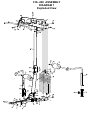
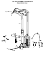
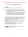
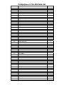
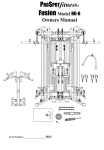
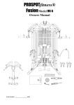
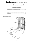
PROSPOTfitness
®
Model FHL-200
Fusion Hi/low with 200 Weight Stack
Option for Fusion HG-1 System
Owners Manual
Table of Contents
Assembly Instructions…………………………………..…… 2-5
Use and Operation of Your PROSPOTfitness® Product…...…. 2, 6
Periodic Maintenance of your PROSPOTfitness® Product….…. 7
Parts List……………………………………………………... 8
Warranty & Contact Information……………………….……. 9
Serial Number: 18607D00000FHL-200
-- 1 --
Instructions for Assembly of the ProSpotfitness® FHL-200
Option for the model ProSpotfitness® HG-1 unit.
•
This optional accessory FHL-200 is for the HG-1 system and can easily be attached to an existing HG-1
System.
•
Approximate assembly time is 1/2 hour.
•
You will need the following tools:
• 17 mm (11/16”) Hex Head Wrench
• 19 mm (3/4”) Hex Head Wrench
• Philips screw driver
• Pliers
•
Floor Padding, such as cardboard, to avoid scratching your floor during assembly.
•
A good pair of scissors will be helpful in separating the parts from one another while removing them from the
cartons.
•
HAND TIGHTEN all bolts. DO NOT fully tighten bolts until instructed to do so.
•
The ProSpotfitness® FHL-200 uses different lengths of bolts. Be careful to use the correct length of bolt
called for at each step of assembly. Refer to the sizing charts provided.
•
Assistance by a second person is recommended for some steps of this assembly.
User Instructions for the FHL-200
1. Never attempt to lift more weights than you can safely handle.
2. Insert Weight Selector Pin into the Weight Stack to add resistance for use with the upper pulley and
lower pulley exercises.
3. When doing Lat pull exercises adjust Leg Hold Down so Foam Roller is above Users leg. This holds the
User down on the bench.
4. To perform cable exercises using the optional ProSpotfitness® model PBL-65 Bench unit, attach Low Row
Cable (26) with Snap Link (22) to Bench cable. Make sure cable is taut by pulling out Bench.
5. To do a standing Arm Curl attach Extension Chain (18) using Cable Snap Link (22).
-- 2 --
FHL-200 ASSEMBLY
DIAGRAM 1
Exploded View
FHL-200 ASSEMBLY DIAGRAM 2
Assembled view
Instructions for Assembly of the ProSpotfitness® FHL-200
1.
To begin unplug all power supplies from wall receptacle.
2.
Now on your HG-1 unit remove the Protective Cover over the Electronic Box. Unplug Electronic Box, cover,
screws and set aside. Remove the two bolts that hold the Electronic Box Locating Board previously installed
on the Back Cross Brace of the PROSPOTfitness® HG-1 unit.
3.
Attach the Low Row Bottom Assembly (1) to the Back Bottom Rail of the PROSPOTfitness™ HG-1 using
two new bolts (29), four washers (28), two nuts (27) and the Weight Stack Support Bracket. You will not
need the old Electronic Box Locating Board anymore. Tighten bolts securely.
4.
Now reinstall the Electronic Box and Cover with screws just removed.
5.
Remove Weight Stack plates (8) and Top Plate (9) from its Cartons.
6.
Now insert Guide Rod Cups (13) into Weight Stack Support Bracket (7) if not already done. Next insert both
of the Weight Stack Guide Rods (12) into each of the Guide Rod Cups.
7.
Add Weight Plates (8) starting with the bottom #200 weight plate, slide down on Guide Rods. Keep weight
plates in order and facing to front of unit. Repeat until all weight plates are installed. This step is easier with
assistance from another person. Then install Top Plate (9).
8.
Make sure the Guide Rod Cups (13) are in the Lat Boom Assembly (14). Now place Lat Boom Assembly on
top of the Back Top Rail of the HG-1 unit and onto the two Guide Rods (12) into the Guide Rod Cups (13).
9.
Align the Lat Support Frame (14) with the corresponding holes in the Back Top Rail. Attach using two bolts
(30), four washers (28) and two nuts (27) as shown. Now align the holes with the front top rail of the HG-1
and install two bolts (29), four washers (28) and two nuts. Tighten securely.
10.
Install cables: Lat cable (16) & Low Row Cable (26) with Pulleys (24) with bolts (34), washers (33) and nuts
(31) according to diagram 1. Tighten Securely. Sometimes these parts are already pre-assembled.
NOTE: Be sure that the cables are in the groove of each Pulley and that the Cable and Pulleys move
smoothly.
11. Connect the Lat Cable (16) to the Top Plate of the Weight Stack by threading the cable end into the
threaded hole on top of the Top Plate. The threaded bolt on the Lat Cable (16) is the adjustment for proper
cable tension. The threaded adjuster must screw in at least ½”. (If you need more Cable length the Pulley
(24) can moved to the outer adjustment hole on Double Pulley plate (23).) Adjust so there is little slack in
Cable. Tighten Lock nut to hold adjustment. Do not over tighten.
12. Connect the Low Row Cable (26) to the loop located on back of the Low Row Bottom Assembly (1) using a
Cable Snap Link (22).
13. Remove the bottom Weight Storage Post on each side of your HG-1 unit. (If already attached) Using these
two same bolts and washers now install Locking tubes (3). These bolts will screw into per-threaded holes on
Locking Tube (3). Make sure Locking Tubes are straight up and down, then tighten bolts securely.
14. Now insert Lat Leg Hold Down Frames (4 & 5) into Locking Tubes (3).
15. Now install Foam Rollers (6) using Bolts (37) and Washers (36). Tighten securely.
16. Now install Foot Board into Low Row Bottom Frame Assembly (1) and lock into place using Adjustable Lock
Pin (25).
17. The next step is installing the holders for the Lat Bar and Row Bar. The Locking Post Covers of your HG-1
will need to be removed from unit for this part of the assembly. (If already attached) Now install Right Bottom
Lat Bar Holder (44) onto Right Locking Post Cover using bolts (46), Washers (47) and nuts (48). Now install
Left Bottom Bar Holder (45) onto Left Locking Post Cover of HG-1 using bolts (46), Washers (47) and nuts
(48). Next install the two Accessory Spring Clamp Holders (43) onto the upper position of both the Right
and Left Locking Post covers of the HG-1. Reattach Locking Post Covers to your HG-1 and place Lat Bar
and row Bar into their respective holders for storage when not using.
-- 3 --
!!Read!! This Page Before Using Your ProSpotfitness ® Product
Safe Use of Your ProSpotfitness® Product
1.
CAUTION:
This machine involves the risk of possible injury by its user.
2.
THE FOLLOWING RULES SHOULD BE CARFULLY FOLLOWED:
• Consult a physician or other healthcare provider before beginning
an exercise program.
• If you are in bad health or are handicapped, ask for the opinion of
your physician and exercise only under qualified supervision.
• Discontinue exercising if you experience any light-headedness,
dizziness or shortness of breath and consult your physician.
3.
Keep small children and others at a safe distance from all moving parts.
The up and down movement of the weights can be dangerous.
Never allow your fingers, toes, hair, other body parts or loose clothing
to come near weights while they are in motion.
Never attempt to exercise with more weight than you are physically
able to handle.
Prior to every use, inspect your machine to ensure all parts are free
from defect and are fully operational.
Check all fasteners to make sure none have loosened with use.
Tighten any loose fasteners if necessary.
•
•
•
•
4.
Warning: Never perform any maintenance on the unit while the
power supply is plugged into the wall.
-- 6 --
Maintenance of ProSpotfitness® Product
Our products are made of durable materials and have been factory tested to assure
proper function and reliability. Along with our Equipment Warranty, this gives the
owner of our product the confidence of a long lasting relationship with
ProSpotfitness® Inc. Our systems are designed in a way to allow easy
replacement of parts both mechanical and electrical if the need should ever arise.
If you are a new owner of a ProSpotfitness® system, three important things need to
be done to assure prompt service under the warranty:
1. Fill out and fax or mail to us your Product Warranty Registration Card along
with a copy of your sales receipt (proof of purchase) if your dealer has not
done this at time of purchase.
2. Your system needs to be set up properly according to the assembly manual.
3. Follow user instructions on how to properly use the system.
Maintenance Program
Note:
Our products are recommended for climate-controlled environments. Outdoor
use is not recommended and will void the warranty.
Carefully inspect machine before each use to determine that it is free from
defects.
Do NOT use machine if you find:
1. A loose, broken or frayed cable – (needs to be replaced)
2. Any broken, cracked, torn, frayed or defective part of the machine – (needs to
be replaced)
3. Loose bolts or fasteners. Check all fasteners to make sure none have loosened
with use. Tighten any loose fasteners.
5. Pulleys sticking or Cables binding. Check for free movement of all cable and
pulleys.
Adjust or replace if necessary.
Lubrication:
Lubricate the Weight Stack Guide Rods (14) periodically by spraying them with a standard
silicone lubricant found at hardware stores. Do not over lubricate.
-- 7 --
ProSpotfitness® FHL-200 Parts List
Part #
Description
Total Qty
1
Low Row Bottom Assembly
1
2
Foot Board
1
3
Locking Tube
2
4
Right Lat Leg Hold Down Frame
1
5
Left Lat Leg Hold Down Frame
1
6
Foam Roller
2
7
Weight Stack Support Bracket
1
8
Weight Stack Weight Plate
19
9
Weight Stack Top Plate
1
10
Weight Stack Selector Pin
1
11
Weight Stack Selector Rod
1
12
Weight Stack Guide Rod
2
13
Weight Stack Guide Rod Cup
4
14
Lat Boom Assembly
1
15
Lat Bar
1
16
Lat cable
1
17
Rotating T-handle Bar
1
18
Chain Extension
1
19
Nylon Strap Pull Handle
2
20
Nylon Adj. Strap Pull Handle
2
21
Nylon Rope Pull
1
22
Cable Snap Clip
4
23
Double Pulley Plate
2
24
Pulley
7
25
Adjustable Lock Pin
3
26
Low Row Cable
1
27
Hex Nut M12
4
28
Flat Washer M12
8
29
Hex Head Bolt M12*115
2
30
Hex Head Bolt M12*75
2
31
Hex Nut M10
7
32
Inner Sleeve for Locking Tube
4
33
Flat Washer M10
14
34
Hex Head Bolt M10*40
7
35
Socket Button Head Cap Screw M10*45
1
36
Flat Washer M8
2
37
Hex Head Bolt M8*25
2
38
Hex Head Bolt M8*20
4
39
Lat Bar Holder Protective Rubber Tube
2
40
End Cap
2
41
Slider Inner Sleeve
2
42
End Cap
2
43
Accessory Spring Clamp Holder
2
44
Right Bottom Bar Holder
1
45
Left Bottom Bar Holder
1
46
Pan Cross Head bolt M4*10
8
47
Washer
16
48
Hex Nut M4
8
-- 8 --
Warranty & Contact Information
Each PROSPOTfitness® Product comes with a limited parts replacement warranty. Please
refer to the actual warranty card included with your system for specific coverage.
Remember: To activate your Warranty, fill out and fax or mail to us your Product Warranty
Registration Card along with a copy of your sales receipt (proof of purchase) if your dealer
has not done this at time of purchase.
If you have any questions about performance under this limited warranty, please write us at:
PROSPOTfitness, Inc.
Attn: Warranty Service
2000 Newpoint Pl Pkwy Suite 500
Lawrenceville, GA 30043
Office (770) 446-9299
Fax (770)-446-7213
Contacting ProSpot Fitness Technical Support:
Our Service Department can be reached M-F 9-5 pm EST.
Or e-mail us: [email protected]
If ordering replacement parts, please refer to the Owners Manual for part numbers and
description.
Note: Owners Manuals & Warranty Registration cards can be down loaded from our web site.
For more information please refer to our Website at: www.prospotfitness.com
-- 9 --