1
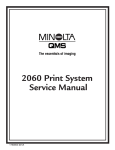
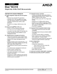
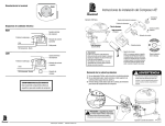
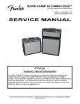
Classic Mac Tech Docs, v1.1: No warranties expressed or implied. Use at your own risk!
Classic Mac Tech Info
1.0 Introduction
Except for minor variations, the analog board for the Mac Plus described in this document
is the same as that used in earlier models (the 128K and 512K/512Ke), and contains the
horizontal, vertical, video and power supply circuits. The horizontal and video circuits are
also virtually identical to those used in the SE and SE/30, but the vertical and power supply circuits are completely different. As will be obvious from the schematics, the vertical
circuit in the classic machines makes sparse use of ICs, so it is a bit “partsy.” However, it is
a reliable design with no history of unusual problems. The power supply, on the other
hand, is notoriously prone to failure, as there is no fan inside the unit (Steve Jobs objected
to the noise, and preferred to risk overheating the machine instead).
2.0 Video Circuit
The video amplifier is a simple shunt-peaked common-emitter amplifier:
FIGURE 1. Video amplifier
+30V
+12-15kV
From
horizontal
circuit
9” CRT
+5V
L4
27µH
R25
470 CR13
9
U2
J4-1
10
8
CR14
CR12
R14
1k
2W
R20
220
NE2
Q7
2N3904
R27
220
CR12-14: 1N4150
(similar to 1N914)
J2-9
7
6
1
2
+12F
3
L5
27µH
J2-8
J2-3
J2-1
J2-5
C15
C17
4
J2-6,7
NE1
C16
Note: C15-17 are
0.01µF capacitors
with 1.5kV spark
gaps
IC U2 is a quad open-collector NAND, one gate of which is connected as a simple inverter
to present the video signal to Q7 with the proper polarity (a low at J4-1 corresponds to
white). Resistor R25 is the NAND gate’s pullup resistor. Diodes CR13 and CR14 form a
Baker clamp to prevent saturation of Q7 when driven hard, thereby speeding up response.
Inductor L4 is a shunt peaking element for boosting the high frequency response of the
video amplifier. Diode CR12 is a protection device, clamping the collector of Q7 to a max-
Classic Mac Tech Info
©2000 Thomas H. Lee, rev. April 17, 2002; All rights reserved
Page 1 of 18
Classic Mac Tech Docs, v1.1: No warranties expressed or implied. Use at your own risk!
imum of a diode drop above 30V, despite inductive kickback from L4, and even if some
CRT fault occurs. Resistor R20 limits the current under the latter fault condition.
The two neon bulbs act as voltage clamping devices to prevent serious overvoltages on the
filament and cathode terminals of the CRT. Similarly, the 1.5kV spark gaps integral with
C15-C17 act to protect the CRT under transient fault conditions.
Finally, inductor L5 provides ac isolation between the CRT and the 12V filament supply.
3.0 Horizontal Circuit
The high voltages in this circuit are all byproducts of horizontal deflection. The TTL-level
horizontal drive signal from the main logic board is inverted by open-collector NAND U2
(here connected as a simple inverter, with pullup resistor R26). The inverted signal then
feeds a small driver transistor Q6, whose output couples to the horizontal output transistor
Q3 through isolation transformer T2. Components R12 and C12 are snubbers that dampen
voltage spikes appearing across the primary of T2 during turnoff of Q6. Flyback transformer T1 has multiple outputs. Pin 2 drives the horizontal deflection yoke, and C3/CR1
generate a boosted VCC at pin T1-4. A special tap (with an integral high voltage rectifier)
provides the 12-15kV 2nd anode CRT potential. Checking the HV rectifier requires a special tester, because it is actually a series stack of numerous lower-voltage units, and ordinary ohmmeters don’t apply enough forward bias to turn it on; you can only test easily for
a shorted rectifier in general. Pin 8, through rectifier CR10 and filter capacitor C14, provides +30V for the video amplifier circuitry. Pin 7. T1-7 (through C8) and the high voltage
kickback appearing at the collector of Q3 (through CR11) together generate up to +500V
for focus at J2-3 and +150-750V for CRT screen grid bias (brightness) at J2-1. The same
kickback, through C7, CR9, R13, and C9, generates –25 to –75V CRT G1 bias (the precise value is determined by the front panel contrast control) at connector pin J2-5.
The circuit includes controls for adjusting width, focus, brightness and contrast. The first
three controls are board-mounted trimpots that are accessible only once the case is opened.
The contrast control is the one accessible to the user at the front panel of the Mac.
Early versions of the analog board used an underdesigned flyback transformer that was
somewhat prone to failure (generally with shorted windings). Interestingly, the analog
board was designed from day one to accommodate two different transformers, which
explains why there are two sets of holes in the PC board for transformer mounting. The
smaller diameter ring of holes is for the original, wimpy transformer. Later production
units used a beefier transformer that had low failure rates.
Other upgrades to improve reliability include a change in (nonpolar electrolytic) C1 to a
50V or 100V unit (from 35V), and changing 3A rectifiers CR1 and CR5 (GI854, equivalent to Motorola MR854) to 5A units. For the latter, Motorola part number MR824 seems
to have been a popular choice.
The schematic for the horizontal circuit is as follows:
Classic Mac Tech Info
©2000 Thomas H. Lee, rev. April 17, 2002; All rights reserved
Page 2 of 18
toroid
+
+12F
+12-15kV
C2
4700µF
16V
+12F
C3
©2000 Thomas H. Lee, rev. April 17, 2002; All rights reserved
+12F
R7
39, 5W
C13
+
+5
12
J4-3
U2
13
R26
470
11
33µF
R12
100
C12
0.01
T2
2
1
220
+ 4 T1
3
CR1
T2 pins are counted clockwise on
bottom side of the board. Pin 1 is marked.
Pin 1 of J2 is nearest the top of the board.
Pin J2-4 is physically absent.
CR10
+
C8
+30V
C14
22µF
C7
0.01 CR11 0.01
R9
1M
R54
2M
Brightness
R15
R53
2M
100k
R16
R5
470k
100k
L3
C4
0.033µF
5
7
R8
100
Q6
2N4401
(inside T1)
8
CR5
Q3
BU406
3
4
1
2
Focus
L1
CR1: GI854 (same as MR854); 3A, 400V, 150ns
CR5: GI854 (“ “) on heatsink (next to Q3)
CR9: 1N4937 (1A, 600V, 150ns recovery)
CR10: 1N4937 (“ “)
CR11: RGP01-12 (1A, 1kV, fast recovery??)
C3: 16V
C7: 1kV
C9: 160V
C14: 50V
C16: 1kV
Q3: BU406 (400BVCBO, 200BVCEO, 750ns, 10A, 60W)
R1
220
L2
R13
100k
R17
1M
C9
CR9
10µF
R57
1M
J2-1 (150-750V)
R18
100k
J2-3 (0-500V)
C1 4.7
width NP 50V
J2-5 (–25 to –70V, typ.)
R19
470k
Contrast
J1-4 grn To horizontal
deflection
J1-3 yel
coil
T1: R1, 2 ~ 0Ω
R1, 3 ~ 0.15Ω
R3, 4 ~ 0.1Ω
R7, 8 ~ 3.3Ω
R8, 5 ~ 1.3Ω
Page 3 of 18
J1 pin 4 is nearest the top of the board.
Pin 1 is marked in the PCB artwork on the back side.
Classic Mac Tech Docs, v1.1: No warranties expressed or implied. Use at your own risk!
+12V
FIGURE 2. Horizontal sweep and high voltage circuit
Classic Mac Tech Info
Flyback pins are counted counterclockwise
when viewed from the bottom side of the board.
Pin 1 is indicated on the PCB artwork.
Classic Mac Tech Docs, v1.1: No warranties expressed or implied. Use at your own risk!
The solder joints on the deflection yoke connector J1 are notoriously unreliable. These
should always be resoldered as a matter of course because a visual inspection does not
always reveal problems such as hairline cracks. Flakiness here results in symptoms that
include an intermittent raster, no raster, or a single vertical or horizontal line in the center
of the CRT. Without question, this is the most common problem with the analog board.
Many old Macs are tossed in the trash because of this; I know, because I’ve fixed many
that were retrieved from dumpsters.
The horizontal windings of the yoke have a low DC resistance (~0.2 ohms). You should
measure an infinite resistance between the horizontal and vertical windings.
The flyback transformer T1 may be checked out with an ohmmeter for basic functionality.
Approximate interwinding resistances are listed on the schematic, and should be used only
as a rough guide. Suspect failure only if the values you measure are very different from the
ones in the schematic. (When testing, also verify the proper lack of continuity between
windings that should not be connected.)
Be sure to use a nonmagnetic, nonconductive hex tool to adjust L2’s core (you can get
these at places like Radio Shack, or make them yourself out of chopsticks, toothbrushes,
etc., if you’re really determined to do everything from scratch). Width increases as the
core is withdrawn from the windings, and is a minimum when the core is centered in the
windings.
There is no adjustment for horizontal linearity, but it is sensitive to L3 and R1, among
other things. Try fiddling with those if you are sufficiently unhappy with the linearity.
Capacitor C1, which does fail fairly often (usually in a visible way -- check for bulging
and cracking at its bottom, where it meets the circuit board), is 3.9µF in many versions.
Replace it only with a nonpolar, low loss (low ESR) unit rated at 50V or more. This
capacitor can be a little difficult to locate on occasion, however, so if you are in a hurry,
I’ve had excellent success substituting a parallel combination of four 1.0µF ceramic disk
capacitors (there’s plenty of room; build it up as a module of four caps, and use two pieces
of bus wire to connect it to the pc board). These are readily available and inherently nonpolar, and the parallel combination reduces the overall ESR to lower values than the suggested replacements.
4.0 Vertical Circuit
Compact models developed after the Plus use the ever-popular TDA1170 IC for the vertical deflection circuitry, but the classic Macs use an equivalent circuit made out of standard
parts and a boxload of discretes:
Classic Mac Tech Info
©2000 Thomas H. Lee, rev. April 17, 2002; All rights reserved
Page 4 of 18
Classic Mac Tech Docs, v1.1: No warranties expressed or implied. Use at your own risk!
FIGURE 3. Vertical sweep generator
+5V
C19 0.01
R30 10k
U1: LM324
U2: 74LS38
+5V
+5V
R29 1M
Height
12
C5
14
9
R55
R22
U1
+
13
0.01 U1 8
47
10
C10
500k 330
R28 10k
CR15 R31
R21 6.2V
10k
0.22
1k
Q5 2N5485
–12V
+5V
+5V
U1 is powered off of
+12V and –12V
R24
1
470
3
U2
2
high=retrace
C20
low=retrace
R23
470
4
6
5 U2
Q1, Q2: EBC (2A, 40V, 10W, 50MHz)
Q4: EBC
Q5: DSG
3
1
2 U1
Q1
MPSU01
CR3
R3
1.5
CR2
C6 +
22
R2
1.5
+
R4 To vert.
100 deflection
coil
CR4
J1-2 red
Q2
MPSU51
R6
4.7k
C11 33µF
CR2-7: 1N4150
CR8: 1N4001
CR15: 1N5234B
J1-1 blue
R58
100
+5V
J4-5
+12V
R10
10k
Q4
2N4401
R11
1.5
+5V
+5V +5V
CR7 CR8
C22
CR6
–12V
C23
–12V +12V
The asymmetry in the current-handling capabilities of the various power supply voltages
leads to somewhat idiosyncratic circuit design here. The vertical yoke is referenced to the
+5V supply instead of ground, and the driver circuitry swings above and below this value.
The aim of all magnetic deflection circuits is to cause (to first order) a sawtooth current to
flow in the yoke. In this circuit, feedback is used to force this condition. The voltage
across R11 is proportional to the current flowing in the yoke, and the voltage at J1-2 is
therefore a measure of yoke current, offset simply by 5V. The third op-amp compares this
current signal to the sawtooth voltage generated by (resettable) integrator formed by the
middle op-amp, and adjusts the base drive of Q1 and Q2 accordingly to maintain equality.
The height is adjusted by varying the RC time constant of the integrator, accomplished
here by tweaking trimpot R55.
Resistor R4 is a dummy load that keeps the loop happy even if the yoke is disconnected or
otherwise open-circuits.
The incoming vertical sync signal at J4-5 is normally high during sweep. It goes low when
the sweep is to reset. The top inverter-connected NAND gate activates integrator reset
switch Q5, zeroing out the charge in the integration capacitor C10. This action forces pin
14 of op-amp IC U1 to go to 5V. After the switch is opened, the integrator ramps linearly
up from 5V.
Classic Mac Tech Info
©2000 Thomas H. Lee, rev. April 17, 2002; All rights reserved
Page 5 of 18
Classic Mac Tech Docs, v1.1: No warranties expressed or implied. Use at your own risk!
The bottom inverter activates Q4, effectively increasing the negative rail for the output
buffers to –12V from ground for a brief interval.
The vertical deflection yoke measures about 8 ohms or thereabouts at DC, and should
show no continuity to the horizontal deflection windings. As with other such measurements, only gross departures from the nominal DC values should be considered cause for
suspicion.
5.0 Power Supply Circuit
Another Achilles heel of the classic Macs is the switching power supply, specified to provide a maximum output of something like 60-65 watts. Unfortunately, the original
designer underestimated the special demands that switchers place on components (such as
filter capacitors and rectifiers), especially when there is no fan to keep things cool. As a
result, the unit is underdesigned and prone to failure.
The power supply may be decomposed into two main modules. One simply takes in
120VAC and produces a raw, +170V unregulated source. The second converts this high
voltage into three regulated DC outputs: +5, +12 and –12V. Only the +12V output is actually regulated directly; the rest are slaved to the +12V output through transformer turns
ratios. A linear regulator IC on the motherboard produces a –5V output from the –12V
produced by the main power supply.
The first module takes the signals from all three terminals of the AC power line, and filters
them through line filter LF2, which is trifilar wound on a toroid. A fuse and spike-suppressing capacitor C38 protect the unit from gross faults. One more line filter, LF1, with
R61, C33 and C37 complete the functions of protection and EMI suppression ahead of the
on/off switch. Thermistor R39 limits surge currents through the bridge at powerup. Capacitors C35 and C36 filter the output, and bleed resistor R41 improves safety by discharging
the deadly filter capacitors when the computer is turned off. This part of the circuit is very
reliable, and has no known pathological failure modes.
FIGURE 4. Raw 170VDC power supply
LF2 pins are counted counterclockwise (foil side).
R39 is a thermistor. CR23-26 are 1N4007.
Pin 1 is marked on foil side of PCB.
SW1
R61
C38
R39
On/Off
0.1µF LF1 470k
1 LF2 3
Vac (to startup circuit)
3
2
C33
120VAC
C36
+170VDC
4.7nF
2
4
1
4
R41
+
+
CR23-26 C35
2.5A
100k
Grn
C37
100µF
250V
wire
4.7nF
ground
200V 100µF
Chassis
200V
ground
Primary
LF1 pins are marked on component side of board. ground
Classic Mac Tech Info
©2000 Thomas H. Lee, rev. April 17, 2002; All rights reserved
Page 6 of 18
Classic Mac Tech Docs, v1.1: No warranties expressed or implied. Use at your own risk!
The switching power supply proper has three different subparts. One is a feedback controller, another is the actual switching converter, and the final is an array of output rectifiers and filters. The latter two subcircuits are where the most frequent failures occur.
First, here’s the control circuit:
FIGURE 5. Feedback control circuit
+12V
U1 is an LM324 quad op-amp.
R34
1k
1N5234B
0.1µF
U3
4
7
CR19 6 U1
11
6.2V
R35 1k 1%
C21
+12V
5
–12V
R37 10k
5
1
To switching
converter core
4
2
C27
R56
0.022
500
C28 0.001
R38 1.2k 1%
R36
470
logic ground
The feedback control circuit monitors the +12V supply voltage through a voltage divider
comprising R35, R56 and R38. This divided-down voltage is compared with a 6.2V zener
diode-derived reference voltage (from R34 and CR19). The system tries to maintain equality of the voltages presented to the input terminals of the op-amp by driving the switching
converter more or less hard as necessary to maintain a constant output voltage. An
optoisolator (U3) couples the control circuitry, which is all referenced to digital ground, to
the core switching converter, which is referenced to primary ground. Resistor R56 (located
just above the speaker) allows fine adjustment of the output voltage. Stability of the feedback system is assured by C21, R37, C27 and C28, which together constitute a combined
lead-lag compensator.
If the +12V supply voltage is too low, the LED inside the optoisolator is driven with less
than normal current. This, in turn, reduces the current through the optoisolator’s transistor,
which ultimately commands the switching core to increase its output. The opposite happens if the supply voltage is too high. This inverse relationship between LED drive current
and power supply output can be understood studying the schematic of the switching converter proper:
Classic Mac Tech Info
©2000 Thomas H. Lee, rev. April 17, 2002; All rights reserved
Page 7 of 18
Classic Mac Tech Docs, v1.1: No warranties expressed or implied. Use at your own risk!
FIGURE 6. Switching converter core
5
T3
(Comp.
Side
View)
8
9
Vac (from raw
170V supply)
C34
T3 330pF
33nF
R40
10
220
C40
T3
7
6
+170V
CR27
1
C32
0.47, 400V
10
Q11
2SC2810
T3: R6, 7 ~ 0.1Ω
R7, 8 ~ 0.5Ω R50
R9, 10 ~ 0.1Ω 1.5
Q10
E0122
C41 0.1
R44
From U3-5
R46 100
22, 1W
From U3-4
T3
7
4.7
R48
100
CR28
1N4934
R49
1.5
Q9
2N3906
R45
1k
R59
6
CR29
1N4934
R60
1k
R51
15
R52
10k
C42 + C43
R47
1.5
0.1
R42
1k, 1%
CR30
1N4007
470
10V
Q9: EBC
Q10: KGA; also E0102YA
Q11: 7A, 4-500V, 50W, 18MHz
CR27: 1N4937 (1A, 600V, 150ns)
CR28, CR29: 1N4934
(1A, 100V, 150ns)
Q11: BCE (on heatsink)
C39
(2SC3039 is a substitute)
470
+
10V
primary ground
Transistor Q11 acts as a switch. When it turns on, the current through the primary of T3
(pins 9 and 10) starts ramping up, coupling energy to numerous secondary windings (only
one of which is shown in this schematic). One secondary winding shown in the figure (T36) is connected to the base of Q11 (through R46) with a polarity that provides regenerative
(positive) feedback, causing Q11 to latch, and assuring continued charging of the output.
As current builds up, the voltage at the top of R47-49 rises, causing more and more current
to flow through Q9, and a consequent increase in the voltage drop across R45. Eventually
SCR Q10 turns on, shorting the base of Q11 to a negative rail generated by the secondary
winding shown (pins 6 and 7), after rectification by CR28 and filtering by C39. The regenerative feedback by T3-6 acts to pull charge rapidly out of the base of Q11, causing a fast
turnoff once initiated. This action also recharges C39 at the same time.
Capacitor C40 feeds the collector voltage of Q11 to T3-8, which is coupled to T3-6, closing a feedback loop that produces oscillation with a switching frequency in the low 10’s of
kHz range.
The voltage regulation loop works by varying the time at which SCR Q10 turns on to shut
of Q11. When the 12V supply voltage has reached the correct value, the feedback control
circuitry steals less current away from transistor Q9, allowing more current to flow
through R45, causing the SCR to turn on sooner. If the 12V supply voltage is too low,
turn-on of the SCR is deferred, allowing more charge to transfer to the output to boost the
voltage.
Classic Mac Tech Info
©2000 Thomas H. Lee, rev. April 17, 2002; All rights reserved
Page 8 of 18
Classic Mac Tech Docs, v1.1: No warranties expressed or implied. Use at your own risk!
Spikes across the transformer windings are snubbed by series RC networks R40-C34 and
R50-C41.
This type of circuit suffers from a “chicken-and-egg” startup problem: if all outputs are
zero, they stay zero. To get things going in the first place, some of the raw ac line voltage
is coupled into this circuit through C32 and R42. It is rectified by CR30 and filtered by
R52, C43, R51 and C42. The resulting modest negative voltage pulls the emitter of Q11
downward enough to turn it on and get things going. Once the switching core has started
to operate, Q11’s emitter voltage rises enough to make the startup network irrelevant from
that point on.
Three of the five secondary windings of T3 are rectified and filtered to provide the +5V,
+12V and –12V outputs, as shown in the following schematic:
FIGURE 7. Power supply output and crowbar circuitry
CR21
T3: R3, 5 ~ 0.1Ω
R4, 5 ~ 0.1Ω
R2, 4 ~ 0.2Ω
3
L8
+
CR20
T3
5
L6, L8: toroid
L7: ferrite bead
+
4
CR20: MBR1035
(10A, 35V)
CR21: IR31D005? 1
(3A, 50V, 35ns?)
CR22: 1N4934
(1A, 100V, 150ns)
CR22
2
C31
1000
L6
C29
2200
+
+
+12V
+5V
C24
2200
L7
C30
+ 220
+12V
C25
1000
Q8
2N6395
12A, 100V
–12V
CR18
1N5927
12V, 1W
R32
12
R33
15
C26
+ 1000
Q8: KAG
All filter capacitors are rated 16V.
CR20, CR21 and Q8 are mounted on heatsinks.
All three outputs are filtered with textbook LC “pi” networks. Adjust the voltage trimpot
so that the +12V output (as measured at the external floppy connector) lies between 11.9V
and 12.75V, and the 5V output lies between 4.85 and 5.15V. Inability to get both the 12V
and 5V outputs within spec can be caused by a failure or drift in components, but most
often is caused by simple deterioration of connector contacts. Simply cleaning power harness contacts, or resoldering where they connect to the circuit boards, fixes 90+% of such
problems.
Weak spots in the power supply design include the rectifiers CR20 and CR21, and the filter capacitors. They run very hot because of the absence of a fan, and this shortens life
considerably. Common upgrades are to use Motorola Schottky rectifier MBR1045 (10A,
45V) for CR20 and (ultra)fast recovery rectifier MUR410 (4A, 100V, 35ns) for CR21. Fast
recovery rectifier CR22 has no documented history of unusual problems, presumably
because the total current pulled from the –12V supply is low.
Classic Mac Tech Info
©2000 Thomas H. Lee, rev. April 17, 2002; All rights reserved
Page 9 of 18
Classic Mac Tech Docs, v1.1: No warranties expressed or implied. Use at your own risk!
The computer is protected against gross regulation failures that would lead to excessive
supply voltages. Twelve ampere crowbar SCR Q8 turns on if there is a dangerous overvoltage (on the order of 15%) on the +12V supply, indicating a regulator failure (or misadjustment of R56). The resulting short circuit shuts everything down. Q8 is a 2N6394 in
some versions; the only difference is that it is rated at 50V instead of 100V. Both SCRs
will work fine.
After the crowbar has been activated, the power supply periodically tries to recover, emitting a characteristic “whup-whup-whup” sound as long as the overvoltage problem persists. To make sure that the problem is not caused by an improper setting of voltage
control R56, turn it to the most clockwise position (when viewed from the foil side of the
PCB) to minimize the output voltage setpoint. If the “whup-whup” sound is still heard, it
indicates a major problem elsewhere.
6.0 Connectors
There are three connectors on the analog board. Most of the connections have been documented piecemeal in the previous sections, but it’s handy to have everything in one place
for quick reference:
FIGURE 8. Connectors as viewed from the component side of the analog board
4
3
2
1
H. yoke
Gnd
V. yoke low
J2
V. yoke high
Classic Mac Tech Info
Gnd
–12V
Gnd
+12V
+4.5V Batt.
+5V
3 4
V. Sync
1
Sound
H. Sync
J4
Video
J1
5
6
7
8
9
10 11
©2000 Thomas H. Lee, rev. April 17, 2002; All rights reserved
1
2
3
G1 bias
5
6
7
8
9
Brightness
NC
Focus
Gnd
Gnd
CRT +12V
CRT cathode
Page 10 of 18
Classic Mac Tech Docs, v1.1: No warranties expressed or implied. Use at your own risk!
7.0 Appendix: More Random Info
7.1 Using PC and Surplus Parts with Classic Macs
Finding parts for Classic Macs can be difficult at times, so it’s occasionally useful to know
how to adapt components intended for the PC world to fix a Mac.
7.1.1 Monitors
The 9” CRT in the classic Macs is definitely cute, but it is just as definitely small. Several
manufacturers once made adapters and monitors that not only expanded the screen’s size,
but also permitted more text to be displayed at any given time. Unlike those products
(which are no longer available), the modification described here only gives you a larger
screen, period. It’s the electronic equivalent of putting a magnifying lens in front of the
existing CRT.
Most older PC monitors are at least 12” in size, and the added area is significant. Unfortunately, they're also often green or amber, and most people find them a little hard on the
eyes when used with a Mac. If you can locate a black and white unit (somewhat rare),
you’ll be a lot happier with the results. You can also interface to a modern color monitor.
Beyond that consideration, there are two technical issues to contend with. One is that the
Mac produces horizontal sync and video signals that are logical inverses of what TTL PC
monitors expect (the vertical sync signal is just fine, however). The second consideration
is that the ~22kHz horizontal sync frequency generated by the Mac is substantially higher
than the ~16kHz expected by old PC monitors, so you'll almost certainly have to fiddle
with the timing network in the monitor to insure synchronization (this issue usually disappears if you are interfacing to a multisync monitor, but the instructions here don’t give the
pinouts for that). Inside some monitors, there is a small trimpot to adjust the frequency. In
others, you will have to change a resistor. Clearly, such a modification is only for those
with advanced circuit skills. Schematics of the monitor are a big help, too. In many old
monitors, a 555 timer IC is used as the horizontal oscillator. Look for one (there may be
two) and, in particular, look for precision 1% resistors (typically there are two of them)
and/or a precision capacitor near the 555. These are almost certainly the timing elements.
Increasing the frequency by a factor of about 1.38 requires a reduction in RC product of
that same factor. The easiest method is probably to place a potentiometer in parallel with
the larger of the two precision resistors. Keep the leads absolutely as short as possible to
avoid interference from other signals generated nearby; you can fry the deflection circuitry
if you do not observe this precaution. Choose a potentiometer whose maximum resistance
is about 5x larger than the fixed resistor it is to parallel. That should give you enough
adjustment range to get the monitor to lock to the Mac's higher sweep frequency. Set the
pot initially to the maximum resistance (and never allow the pot to go too low in value, or
you will once again risk frying the works; always start the pot in the position of maximum
resistance, and work down, taking care not to go too far), and then power up the monitor.
Adjust the pot until the display stabilizes. As an additional check, turn the monitor off then
on again, and verify that lock is maintained. If not, readjust the pot and repeat the test.
Classic Mac Tech Info
©2000 Thomas H. Lee, rev. April 17, 2002; All rights reserved
Page 11 of 18
Classic Mac Tech Docs, v1.1: No warranties expressed or implied. Use at your own risk!
For the necessary signal inversions a cheap 7404 or 74C04 hex inverter IC does fine; just
be sure to include a power supply bypass cap, and ground all unused inputs if you use the
‘C04 CMOS inverter (an alternative is to connect the extra inverters in parallel with the
main ones). The inverted and other motherboard signals should be wired to a female DB-9
as follows:
Motherboard (J4) Signal
DB-9 Pin
------------------------------------------------------1
Video
7 (after inversion)
3
Hsync
8 (after inversion)
5
Vsync
9
7, 9
Gnd
1, 2, 6
7.1.2 Mice
Remarkably, old PC bus mice turn out to have all the same internal workings and output
signals as classic Mac mice. All that is needed to convert for use in Macs is to substitute a
male DB-9 Mac connector for the DIN-9 PC connector as follows:
DIN Pin (PC) Function/Signal DB-9 Pin (Mac)
----------------------------------------------------------1
+5V
2
2
XA/left
4
3
XB/right
5
4
YA/up
9
5
YB/down
8
6
left button
(7)
7
mid button
(7)
8
right button
(7)
9
ground
1
Note that any or all of the PC mouse buttons can be used as the single Mac mouse button.
I’ve wired all the buttons together in all the conversions I’ve done, as shown in the table
above, so that clicking any one of them makes something happen.
7.1.3 Keyboard vs. telephone cables, and keyboard notes
Extremely important: Never substitute a standard telephone cord for the keyboard cable!
The Mac deviously reverses the connections on one end, just to assure incompatibility
with telephone cables. But the situation is worse than mere incompatibility: If you make
the mistake of using a standard telephone cable, you will apply power to the keyboard in
reverse polarity, virtually assuring the destruction of either the keyboard or the Mac (or
both)!
You can modify a standard telephone cable for Mac use by cutting off the connector on
one end, and replacing it with a new RJ-11 connector in reverse order.
Classic Mac Tech Info
©2000 Thomas H. Lee, rev. April 17, 2002; All rights reserved
Page 12 of 18
Classic Mac Tech Docs, v1.1: No warranties expressed or implied. Use at your own risk!
Keyboards from any classic Mac can be used on any other classic Mac, contrary to the
assertions of some. I’ve tested this personally with all models of classic Macs.
PC keyboards are completely incompatible with Mac keyboards (both the keycodes and
hardware interfaces are totally different). There is no practical way to modify them for
Mac use, so just abandon this idea altogether.
7.1.4 Floppy Drives
PC floppy drives are so different from those of the Mac that there is no practical way to
convert them into Mac drives. Both the format of data storage on the disk, as well as the
nature of the interface, are completely different. In particular, Mac drives have more
“smarts” built into them, containing much of the circuitry found on floppy controller cards
for PCs. Also, classic Mac drives vary their rotational speed (spinning faster when accessing data on the outer tracks, in order to maintain a roughly constant linear data density),
but PC drives run at a fixed speed and have no means for varying it. So, just give up the
idea of converting a PC floppy drive for Mac use, especially since inexpensive used Mac
drives are now readily available on the surplus market. This difference also explains why
you can never read 800K disks in a PC floppy drive. Software, no matter how cleverly
written, cannot overcome the fundamental hardware incompatibility. The Apple Superdrive (FDHD) is a complex widget that manages to accommodate 800K/1.4M Mac formats, as well as 1.4M PC formats. But standard 1.4M PC floppy drives are much less
capable mechanisms, making the transfer of data from old Macs to PCs through 800K
floppy disks (“sneaker net”) impossible.
Alas, there does not appear to be any simple way to use Superdrives on classic Macs. Connecting a Superdrive to a classic Mac merely gives you another 800K drive; the extra
capability is ignored. A company called Applied Engineering once made a unit called the
AEHD+, which did impart 1.4M capability to old Macs such as the Plus and original SE
(except that you could not boot from the AEHD+). It accomplished this by integrating a
special controller card, working in tandem with special driver software. The AEHD+ is no
longer made, and is rare enough not to show up too often even at places like eBay, unfortunately. If you do locate one, make sure that it is the AEHD+, and not just the AEHD. The
latter is a plain old 1.4M drive for use with machines that already support such drives.
When connected to a Plus, an AEHD will simply behave as an 800k drive.
Contrary to popular belief, an 800K drive can be used on a Mac 512K without first performing a ROM upgrade (or any other hardware modification), as long as the HD20 init is
installed. This init (available for free download from Apple’s own website, ftp://
ftp.info.apple.com, as well as numerous other sites) patches the system file to enable the
HFS filing system. The Mac 512KE (and the Plus) already has this code in its upgraded
ROM. The HD20 init can be downloaded from a number of ftp sites, including Apple’s.
Occasionally, you may encounter problems after installing 800K drives in the older models. Cutting pin 20 of the floppy cable often solves many of these problems. The signal on
this pin controls the floppy speed in 400K drives. 800K drives do not use this signal, but
some revs of 800K drives may be confused by its presence.
Classic Mac Tech Info
©2000 Thomas H. Lee, rev. April 17, 2002; All rights reserved
Page 13 of 18
Classic Mac Tech Docs, v1.1: No warranties expressed or implied. Use at your own risk!
If you find that the eject motor of a newly installed 800K drive runs continuously, cut pin 9
of the floppy cable. This pin supplies –12V, which is used only by 400K drives. Mid-production runs of 800K drives ignored this wire. However, later 800K drives evidently use
this pin for some other purpose (perhaps for production test?), and connecting –12V to it
makes those drives misbehave.
7.1.5 Floppy drive head connections
Heads rarely go bad electrically (much more commonly, they suffer from various forms of
mechanical abuse). But, it's possible. Luckily, testing the heads is pretty easy to do with an
ohmmeter. All resistances given in the following are very approximate:
R23: 50 ohms
R24: 25 ohms
R25: 35 ohms
R34: 30 ohms
R35: 40 ohms
R45: 10-15 ohms
Pin 1 is not connected to anything.
Only gross departures from these approximate resistance values (e.g., open circuits)
should be interpreted as a problem.
The connector for the bottom head on a dual-head drive (800K/1.4M) has terminals
labeled 1-5 going from left to right when viewed with the edge fingers facing you and
pointing down. The connector for the top head has terminals arranged as the mirror image
of the bottom head's connections.
7.1.6 Using 1.4MB floppy disks in 800K drives
Since 800K floppy disks are now considered obsolete, they are less widely available than
they used to be. In a pinch, you may use a 1.4MB disk in 800K drives by covering up the
media identifier hole (the one without the plastic write-protect slider) with a piece of tape.
There’s a lot of lore about this operation resulting in unstable data, etc., and it does have a
basis in fact: 800K disks require less magnetic force to write, so 1.4MB disks are written
with somewhat less than optimum strength. However, the media are close enough in characteristics that this is usually not a real problem unless the 1.4MB floppy has previously
been written on by a 1.4MB drive. The weaker write fields of 800K drives may not be sufficient to reliably over-write existing data (including formatting data). So, use only virgin (not just empty) 1.4MB floppies in an 800K drive. If you follow this rule, you’ll have
few (if any) problems.
7.2 How to Upgrade the Mac 512K to 1MB (and beyond?...)
These days, most owners of 128K/512K Macs prefer to keep their Macs in their original
condition; in fact, there’s even a movement toward restoration of upgraded machines back
Classic Mac Tech Info
©2000 Thomas H. Lee, rev. April 17, 2002; All rights reserved
Page 14 of 18
Classic Mac Tech Docs, v1.1: No warranties expressed or implied. Use at your own risk!
to factory-original status, to make them more collectible. This section is not for those
folks. This section is for people who insist on making these old Macs more useful, and
who don’t mind wasting a large amount of time doing it.
Achtung! These instructions assume an understanding of how to remove the motherboard,
how not to kill yourself from CRT discharge or implosion/explosion, familiarity with
proper ESD protocol and knowledge of circuit prototyping methods. If these are bad
assumptions, chances are high that this particular upgrade is not for you. Even if these
assumptions are correct, this upgrade is not a trivial one by any means, so it’s definitely
not for the faint of heart.
If that disclaimer hasn’t scared you off, then let's proceed. First, here’s a list of the parts
you will need:
16 150nsec (or faster) 256kb DRAMs (standard DIP package)
1 74LS138 demux chip
1 16-pin low-profile wire-wrap DIP socket (optional)
1 0.1uF ceramic capacitor
1 1kilohm, 1/8 or 1/4W resistor
4 47-ohm, 1/8 or 1/4W resistors
1 small piece of vectorboard or similar (large enough to hold the ‘138, resistors and
capacitor)
hookup wire (26-30AWG)
These days, 256k RAM chips and 256K RAM SIMMs are obsolete. You should be able to
find them at surplus electronics shops for almost zero dollars. I obtained mine for free at
an electronics flea market. A future revision of this document will include instructions for
how to modify those ubiquitous (and generally free) 256k RAM SIMMs for use in upgrading a Mac512K to 1MB (less wiring!), but the instructions that follow here are assume you
have individual DRAM chips.
In what follows, reference is often made to various coordinates, such as “D3” and the like.
Labels for these coordinates may be found along the edges of the motherboard.
Step 1: Solder the DRAMs onto the existing DRAM chips (located at positions F5-F12
and G5-G12), “piggyback” style, except for pin 15 (CAS_b) of each added chip; leave
those free. Take care to orient all the chips properly! Pin 1 of each chip should point away
from the 68000 microprocessor in the center of the board, and toward the nearest edge of
the board, the same as the existing memory chips. It is important that the added DRAM
chips all have the same access speed, so they should all be 150ns parts, for example, or all
120ns. Mixing speeds can cause erratic behavior. Note that the added chips only have to
match each other in speed; they need not match the speed of the original 512k chips. Note
also that, since overall memory timing and processor speed are controlled by a crystal
oscillator, using DRAMs that are faster than the 150ns recommended value cannot, and
will not, speed up the Mac in any way (contrary to what Larry Pina, author of Mac
upgrade books, claims).
Classic Mac Tech Info
©2000 Thomas H. Lee, rev. April 17, 2002; All rights reserved
Page 15 of 18
Classic Mac Tech Docs, v1.1: No warranties expressed or implied. Use at your own risk!
If the near-irreversibility of soldering chips directly onto other chips concerns you, you
may wish to solder low-profile sockets onto the existing DRAMs instead. Just be sure that
there’s then enough room to slide the motherboard back into the chassis when the added
chips are socketed!
Step 2: Very carefully bend pin 15 of each of the added chips (or sockets) with a small
needlenose so that, from a side view, each pin forms a “U” shape. The idea is to have the
pins up in the air a bit so that a wire running horizontally across the array of chips can connect all of the pins 15 together. Just bending a pin from its normal down position into a
straight-up position is a bit risky (the pins break off easily from the body of the chip),
hence the “U” bend idea. Make sure to bend each pin enough to avoid shorting to pin 15 of
the chip underneath.
Now connect all the pins 15 of each row of added DRAMs together, keeping the two rows
electrically separate. Leave enough wire in both cases to reach all the way to roughly chip
location D3. These will be connected later.
Step 3: Locate the TSM chip, positioned at D1. Carefully and cleanly cut the traces leading to pins 12 and 13. One line is on the component side of the board, and the other isn’t.
Step 4: Prepare the vectorboard as follows: Install the 74LS138 chip, and connect a 0.1uF
capacitor across pins 8 and 16, keeping the leads of the capacitor as short as possible. Connect pins 4, 5 and 8 together. Then connect the 1-kilohm resistor from pin 16 to pin 6.
Next, connect a 47-ohm resistor in series with each of pins 10, 11, 12 and 13. We will refer
to the free ends of those resistors as pins 10R, 11R, 12R and 13R. Then, figure a way to
mount this whole assembly securely on the motherboard, keeping in mind that you will
eventually be connecting wires to pins 1-3, 10R-13R as well as 8 and 16 (ground and +5V,
respectively). The space between location E3 and the 68000 may be a good choice. If you
use a low-profile wire-wrap socket, its stiff pins might be useful in providing a stable
mounting option.
Step 5: Connect pins 2 and 3 of the ‘LS138 to pins 12 and 13 of the TSM chip@D1,
respectively, with wires that aren’t longer than necessary. Then connect pins 11R and 13R
to pins 7 and 9 of RP3, respectively. RP3 is a SIP resistor pack positioned next to the
DRAM array at around G5. Making connections to RP3 on the component side of the
board is very difficult, so it is probably best to route two wires through the PC board via
hole conveniently located pretty close to RP3, and make connections on the other side. Try
to keep these wires as short as possible as well. Next, connect pin 12R to the common pins
15 of the piggybacked DRAM row nearest the edge of the motherboard. Finally, connect
pin 10R to the pins 15 connection of the other added row of memory chips. As before,
keep these wires short.
Step 6: Connect pin 1 of the ‘LS138 to pin 3 of the TSG chip located at D3. Finally, get
power to the ‘LS138 by connecting its pins 8 and 16 to pins 10 and 20, respectively, of the
TSG chip.
Step 7: Check your work carefully to make sure there are no solder bridges, and that
everything really is wired up correctly. Then reinstall the motherboard and test out the
Classic Mac Tech Info
©2000 Thomas H. Lee, rev. April 17, 2002; All rights reserved
Page 16 of 18
Classic Mac Tech Docs, v1.1: No warranties expressed or implied. Use at your own risk!
Mac. Under “About the Finder” in the Apple menu, you should see that the memory has
increased to 1MB.
For reference, the “official” signal names for the connections made are as follows:
TSM-12: CASL_b; TSM-13: CASH_b
TSG-3: A19
‘LS138-10R: CAS1L_b; ‘LS138-11R: CAS0L_b
‘LS138-12R: CAS1H_b; ‘LS138-13R: CAS0H_b
Pin 15 of each DRAM is CAS_b
Note that expansion to a maximum of 4MB is possible in principle if 32 1Mb chips are
used (in which case the original DRAM chips are effectively removed from the circuit),
and if the address decoding is modified accordingly. However, 1Mb DIPs have 18 pins and
a pinout that differs significantly from that of the 256k generation, so that particular modification is only for the truly hardcore!
7.3 Keyboard Repair
Keyboard keys have to withstand considerable abuse. Physical punishment, combined
with the occasional spilled soda, can result in flaky behavior, or just plain failure. Fixing
the individual keys themselves is actually straightforward; it’s getting the actual key
switch out that’s the hard part. Given that difficulty, it might be worth trying a quick fix
first: Some people (but not me) have had luck spraying the internal guts of the keys with
WD-40 (or similar). I always just end up with a greasy mess. Others have placed the keyboard in a dishwasher! I am not so brave, but if the keyboard otherwise seems a total loss,
I guess there’s no harm in trying one last desperate act.
If a quick fix doesn’t solve the problem, you’ll have to do a little more work. First, open up
the keyboard and remove the circuit board. Gently pull off keycaps until you have cleared
a sea of keys centered around the defective key. You may wish to start from one edge of
the keyboard and work your way to the defective key. This may require the removal of lots
of keycaps, but it minimizes the risk of damaging them. Keep track of where they go.
Note the four small slots at each corner of the plastic cover of the key switch. Insert a
small jeweler’s screwdriver into one of the slots. While prying toward the nearest edge of
the switch, use a second screwdriver to pry that edge of the switch up a bit. Do the same
operation at each of the four corners of the switch. When the switch is out of the keyboard
a decent amount, gently pull it out the rest of the way by the stem that protrudes from the
middle. Warning: There’s a little spring inside, just waiting to pop out and disappear into
thin air, so be prepared for it! It’s very easy to lose.
Now that you have the switch proper out and free to work on, examine its contacts. The
typical failure mode is that the contacts fatigue a little over time, and stop working reliably
(or at all). Bending the contacts (carefully, and with tweezers or something similar) often
solves the problem (at least for a good long time). Cleaning the contacts with a product
like Cramolin or something similar may be useful in other cases. In any event, be careful
not to touch any conductive surfaces with your fingers, however, or the switch contacts
Classic Mac Tech Info
©2000 Thomas H. Lee, rev. April 17, 2002; All rights reserved
Page 17 of 18
Classic Mac Tech Docs, v1.1: No warranties expressed or implied. Use at your own risk!
will eventually tarnish and fail down the road. Alternatively, replace the key or contacts
using parts from an “organ donor” keyboard. You can even use rarely used keys on the
same keyboard as organ donors in a pinch.
When finished with the repair, reassemble the key, being careful to replace the spring.
Reinstall the keycaps and circuit board, button up the keyboard case, then test. That should
do it.
8.0 Document Revision History
Rev 1.0: Initial release, allegedly Acrobat 3.0 compatible
Rev 1.1: Re-distilled to be Acrobat 2.1 compatible; fixed minor font boo-boos.
Classic Mac Tech Info
©2000 Thomas H. Lee, rev. April 17, 2002; All rights reserved
Page 18 of 18