1
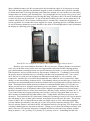
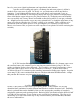
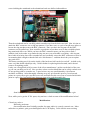
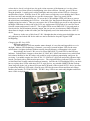
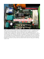
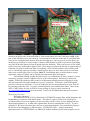
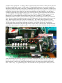
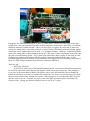
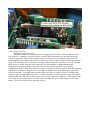
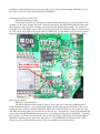
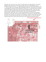
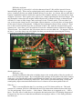
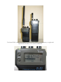
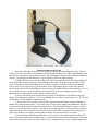
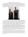
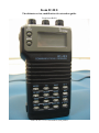
Icom IC-R1: The ultimate review, modification & restoration guide. From Jason Reilly Icom’s IC-R1: 0.1 to 1300 MHz in your pocket. Some of the things my dad would do, I couldn't quite understand as a young boy. Trained as a motor mechanic, dad would buy complete wrecks of cars from the 1950s or earlier and spend anything up to three years lovingly restoring each of them to their former glory. Something of an alchemist, he would be working in the garage turning twisted, rusty bits of metal into something useful for his A-model Ford or '57 Chevy coupe, while I'd be at the workshop bench, a hot soldering iron in hand building up the latest Dick Smith electronic kit that once was pocket money in a 10 year old's piggy bank. I remember thinking how much effort dad put in to these old cars, and how at the end of it all, he'd end up with a car that was drivable and looked neat, but hardly as comfortable or fuel efficient as a modern day car. Driving a 1940s car in a 1980s world wasn't very practical, I thought. Meanwhile, the labour of my efforts produced something 'way cooler' – or at least it seemed that way to one 10 year old boy at the time – things such as an electronic dice or a kitchen egg timer. But now, I'm on a restoration mission of my own. An Icom IC-R1 pocket sized 'communications receiver' – a scanner by any other name – has landed in my letterbox, and while it works fine, it certainly isn't what you'd call in 'factory fresh' condition. As that ten year old boy grew older and got his first job, so did the 'pocket money' grow. As a result, various models of scanner came & went, always looking for a radio that I'd be happy with. Scanning back then was a pretty simple affair: no trunking, certainly no digital radio transmissions, heck, even analogue cellular mobile phones were yet to arrive in these parts. Likewise, scanners of the time were also pretty simple; your main choices for years were 'do you want 10 or 50 memory channels' and 'would you like airband reception with that, sir?' Then in the late 1980s, scanning radio receiver technology started to take off. Tandy / Radio Shack & Uniden started to bring out models that had 800 MHz reception in them as well as airband reception as standard. Yupiteru came out with the MVT5000, that people were calling the first 'super scanner' with reception from 25-550 and 800 -1300 MHz coupled with AM & FM reception modes independently user selectable on any frequency, giving hobbyists access to some pretty interesting slices of the spectrum for the first time in a handheld. Not to be outdone, AOR soon released their AR1000 which had a mindboggling 1000 memory channels and 8-600 and 805-1300 (later 0.5-600 and 805-1300) MHz reception. The Icom IC-R1 in review: Icom couldn't let this challenge go unanswered, and in December 1989 released to the world the IC-R1. It pushed the frequency coverage envelope even further: 0.1-1300 MHz with no gaps, and a reasonable 100 memory channels, plus some new features never before seen on a handheld scanner such as a built in clock which could turn on or off the radio at a pre-determined time, a snazzy little RX indicator LED, a ten segment signal strength S-meter and a line-out socket for recording things you hear. Of course it just wouldn't be an Icom without the range of accessories available such as a desktop drop in charger, slide-on extended capacity battery packs and protective leather cases. But the most noticeable aspect of the IC-R1 is also the smallest: its size! The R1 was two and a half times smaller (by volume) than the average scanner available at the time. And naturally, I just had to have one. In 1990, it cost around $750 from a genuine Icom dealer to own one (around $1400 in today’s terms) so it wasn't cheap, though by shopping at non Icom authorised outlets you could shave off a few dollars. Compare that with $429 for a Uniden BC-200XLT, $499 for a Yupiteru MVT5000 or $599 for an AR1000 at the time. The little Icom certainly had lots to endear itself to scanning folk. Stylish good looks, Icom's famous build & finish quality, innovative features and unparalleled frequency coverage in a handheld smaller than anything ever seen before. Multiple reception modes are at the complete control of the user with AM, FM and WFM available no matter what frequency you’ve entered, and coupled with multiple step sizes of 500 Hz, 5, 8, 9, 10, 12.5, 15, 20, 25, 30 & 50 kHz, you could cater for just about any listening requirement. Icom didn't skimp in the sensitivity department, either, with excellent ability to pick up weak signals even by today's standards – though like most other wideband scanners, the R1 becomes quite deaf towards the edges of it's frequency coverage. The built-in battery pack that sits behind the keypad is rated at 300mA/h and is good for listening for about three hours of average listening, and if that isn't enough, you can call upon several battery saving features to increase your listening time. For example the receiver power-saving ‘sleep’ time can be set between five different levels, the little RX busy LED above the LCD can be disabled, and even the key beep can be turned off. To top off all this flexibility, the user can also adjust the LCD contrast, and set the IC-R1 to resume scanning either 2 seconds after a signal has disappeared or resume regardless 10 seconds after it has stopped at a signal. Scanning speed is switchable between 10 and 20 memory channels a second, and there's the usual LCD backlight which evenly illuminates the display in a pleasing green light. Icom IC-R1 size compared to Uniden UBC-200XLT: is bigger always better? But there were some oddities about the IC-R1 too, however. Memory 'banks' were nowhere to be seen on the little Icom, but the user was compensated with some flexible scanning options: you could nominate scanning between two specified memory locations, or scan only AM or only FM frequencies, and you could selectively skip memory channels too. Confusingly, Icom called the process that we normally know as 'searching' with the term 'programmed scan' – but a search never the less it is, and you can designate ten individual search ranges to seek 'n destroy your frequencies. Another type of search will automatically store whatever active frequencies it finds during a search into memory locations 80-99. Unfortunately when you start this type of search, the microprocessor automatically deletes memory channels 80-99 in preparation for storing whatever it finds. That makes these twenty memory locations of somewhat limited utility for 'everyday' use, unless you plan on never using the auto memory write scan feature. Another handy facility is the ability to nominate up to 60 frequencies that will be skipped in programmed scan (search) mode... but those frequencies have to come from somewhere, and they occupy memory locations 20-79. So if you want to skip any frequencies during your searches, you have to program them in to one of those memory locations and 'skip' that memory first – biting further still into your precious 100 memories. You could still use all 100 memory channels for scanning of course, but if you wanted to take advantage of some of these other features, some had to be sacrificed to the cause. The priority feature of the IC-R1 is a little different to what you might expect as well: rather than sampling a 'priority channel' periodically, Icom ask you to enter your priority frequency into the VFO. Then, once the priority feature is activated, the R1 will alternate between your priority VFO frequency and a memory channel that you also want to listen to. Things get even more interesting in memory scan mode, where the VFO priority frequency is sampled in between each and every memory channel being scanned i.e.: ch 1, priority, ch 2, priority, ch 3, priority, ch 4 etc. Something else that isn’t quite right on the IC-R1 is the squelch action. Normally, squelch action is very definite, and you can set the squelch control to a ‘knife edge’ on most receivers to ensure the very weakest signals are heard. The IC-R1 squelch is a little indecisive; if you set the squelch to where it is just closed – the so called ‘knife edge’ setting, you’ll find the IC-R1 squelch pops open and closed ever so slightly. This means you have to advance the squelch somewhat past the knife edge point for reliable operation. Thankfully, weak signals are not missed due to this. Another oddity is that in AM mode, the S meter will never read above S9 no matter how strong a signal is pumped into it, whereas FM & WFM readily will. So that covers the good & the quirky. What about the bad? If you have big fingers, you'll immediately notice that the tiny keypad buttons are a little awkward to push, and the small knobs on the top panel are similarly also not designed for fat digits. However the worst aspect of this miniature scanner is that it is prone to reception problems. The IC-R1 is impressively sensitive across most of the bands and while the 150 milliwatt audio output won’t blow your eardrums to pieces, it sounds clear and articulate enough. No, the big problem with the IC-R1 is that it has some major issues with selectivity. Often a 'phantom' signal is received on a displayed frequency that simply isn't really there. If you've experienced 'image frequencies' on other scanners before, you'll know what this is all about. The IC-R1 is, unfortunately, plagued by similar issues. While this might not be a problem for users in a small country town where radio signals are few and far between, users in a major metropolitan city or close by to a radio transmitting station will soon be tearing their hair out. As an example, let’s say you are listening to a moderately strong signal on 164.000 MHz. As you tune around this frequency, you'll hear that same signal again on every frequency from 163.750 MHz through to 164.300 MHz. The stronger the signal, the worse the problem gets spreading out to more and more phantom frequencies, and is worst about 190 kHz away from the real frequency, where the real signal only has to be -100dBm or around 2 microvolts (about an S3 on the R1's signal meter) for it to begin to appear as a phantom signal. Technically speaking, this is a problem with the third IF ceramic filter 'spurious response' that all ceramic filters exhibit to some degree, though normally this is negated by clever receiver design. Unfortunately Icom had to cut some corners to make the IC-R1 so small, and had to sacrifice something. (This can be vastly improved upon by a modification, read on below for this) Another issue occurs when certain VHF frequencies are received when tuned to a UHF frequency, and vice versa. For the geeks reading, this happens because a harmonically rich Local Oscillator is employed in the receiver. If you need a LO of 600 MHz to receive a particular frequency for example, you could just use a LO of 300 MHz (which is much easier to generate) and use it's second harmonic. This simplifies the design of the VCO to generate the Local Oscillator frequencies, which in turn reduces component count of the VCO, keeping the circuit as small as possible. The consequence of this is that if you do happen to need a LO of 600 MHz, the fundamental frequency of 300 MHz is still there. Any incoming received signals will mix with BOTH these frequencies; and as a result unwanted signals can be received on tuned frequencies far from where they really are. Again, clever circuit design can overcome this issue, but at the expense of making the circuitry more complex and physically bigger – all of which the IC-R1 needs to avoid to keep it as small as possible. So in terms of signal selectivity, the IC-R1 is a real compromise. Some would argue that it sacrifices too much in this regard, and I tend to agree with this sentiment. There is still one aspect that hasn't yet been discussed about the IC-R1: it's abilities on the HF or shortwave bands. Here another problem comes to the fore: the IC-R1 has a very 'noisy' receiver in this part of the spectrum. Internal microprocessor noises & birdies are found in copious quantities below 30 MHz (almost constant noise below 4 MHz), which tends to spoil reception somewhat. I also found multiple FM broadcast stations were mixing together in the front end and producing their sum differences in the HF band e.g.: a particularly strong FM broadcast signal on 93.3 MHz mixes with another station on 103.7 to produce a weird mish-mash of the two stations on 10.4 MHz – and every strong FM broadcast station will mix with another, potentially creating dozens of mixing products across the HF band. Combined with the 3rd IF ceramic filter spurious response issue identified above, and you can see that tuning through the HF band isn't going to be a pleasant experience on the little Icom. In laboratory conditions, the IC-R1 is still decently sensitive at HF, yet it is barely adequate to listen to any but the very strongest of shortwave broadcasts, anything weaker is masked by spurious mixing products & internal noise. You could use a larger antenna to capture more signal, and the IC-R1 will certainly then receive more shortwave signals, but then you’ll exacerbate the interference & selectivity issues. I found that a telescopic whip was an excellent choice for HF reception on the R1 – you could lengthen or shorten the antenna as the situation demands it – longer for capturing a better signal, or shorten it to reduce the amount of interference & overload received. HF reception is also noticeably improved if you have the IC-R1 held in your hand or sitting on a large metal surface while listening to act as a ground counterpoise. Down very low in the HF bands, the IC-R1 is very insensitive, to the point that on a test drive with the little Icom, it needed to be within 100 metres of a 500 watt NDB on 300 kHz to be received with the stock antenna. And what about SSB? There is none. Tantalising clues exist that Icom may have originally planned to equip the IC-R1 with SSB (why else would they have gone to the trouble of including a 500 Hz step on a radio such as this?) but clearly decided against it in the end. Adding in SSB reception is possible, via a modification detailed below, however. Having purchased & owned the Icom IC-R1 from new back in 1990, despite its faults it became a talkative companion that I could (and did!) carry just about everywhere with me. We'd had some adventures together in those few years, but in the end I decided that it was time to move on to another scanner. I never regretted that choice, but all the same, I did miss the little Icom. It’s funny how we become attached to inanimate objects and begin to talk of them as though they were long lost friends, isn't it? Restoration tips: Present day. A bit of disposable income and sentimental nostalgia combine to once again fuel the desire for me to get another Icom IC-R1. Like any radio that is getting on to 25 years old, finding one that is in excellent condition is not easy. Most will require at the very least a new internal battery pack; the IC-R1 that I have recently received is no exception. The good news here is that the original 300 mA/h pack can be substantially improved upon with 600 and even 750 mA/h capacity replacement packs being available that fit into the same space. The battery pack has an inline connector, making replacement no more complicated than undoing the screws that hold the R1 together, pulling apart the case halves, removing the old pack and plugging in the new one. Another item likely to need attention in the R1 (and many other radios from this era) is the backup lithium battery. If the battery is so old and run down, it may be shorting out the backup power line to the microprocessor, sometimes to the point of preventing it from starting up properly. In theory, charging the internal battery should also charge the lithium cell. A good charge overnight, then resetting the IC-R1 by holding the “F” key on the side of the radio, and the “CL” key top right of the keypad, while turning on the radio power, should see things right again. If not, de-solder the old VL2020 lithium cell, and replace it with a new CL2020 cell (VL2020 cells are no longer available). Something else that can cause problems over time is the power connector on the top panel and the battery contacts for the extension battery packs on the bottom of the radio. Both contain internal change-over contacts that can become dirty or contaminated, which results in the radio not powering up or not charging. To fix this, you'll need to remove the internal battery pack and then flood the top power connector with electronic grade contact cleaner. Immediately 'exercise' the contact by plugging in and removing the charger power cable (making sure it isn't plugged in to the wall outlet!) to help shift any dirt. Then finish off by using some electronic grade cleaning solvent this time to rinse away the dirt, let everything dry off for a good few hours, and reassemble. If the bottom extension battery pack contact is suspect, the same principle applies: remove all power sources, flood with contact cleaner, rinse with solvent, let dry & reassemble. The critical contact here is hidden in behind the larger gold coloured spring leaf. Icom themselves had predicted this would be a problem with the IC-R1, and they warn the user to always use the protective dust cap that covers the power / earphone / line out connectors to prevent dust ingress. Good advice! If you have lost yours, non-original replacements can be purchased on the internet. To get the exterior looking good again, a soft damp cloth and some patience is all that is needed to wipe away years of grime. Go slowly here, you don't want to rub off any labels or imprinting. A soft paintbrush helps remove dust in some hard to reach spots, and a very soft toothbrush will be invaluable to removing any built up dirt in grooves around LCD display lenses, flutes in dial knobs or gaps in between case joins. Scratches in LCD display lenses can be buffed out very carefully with a rotary 'Dremel' tool and the softest buffing wheel you can get your hands on – though beware this can also remove any nearby printed labels, or change the appearance of any matte (anti-reflective) finish to the LCD lens / window or its surrounds. Heavy scratches can be polished out with some plastic polish or even gel toothpaste if the scratches are really bad, but there's a bit of an art to this, so practice on some scrap bits of clear plastic first before attempting the real thing. My IC-R1 had paint flaking off the back case half. On the inside of the bottom cap (to cover the extension battery pack contacts if you’re not using an extension battery) of my IC-R1 was a sticker proclaiming it to have been calibrated. There wouldn't be too many organisations out there that would want to have a device like this calibrated for official use. I'd heard stories that the ACMA used Icom IC-R1 scanners taped to small yagi antennas for finding rogue signals. The paint wear on my IC-R1 seems consistent with that, and with that calibration label underneath... perhaps this particular R1 has some very interesting heritage to it? A calibrated Icom IC-R1? Ex-ACMA perhaps? On the R1, the front half of the case is a good quality plastic, but the back half is a die cast aluminium shell, and painted a satin-to-almost-matte black to match the front case half. Thankfully, there's no printed labels on the back half of the case, this opens up the possibility of completely stripping the paint away and repainting afresh. Removing all the electronics from the back case half is a fiddly job, but necessary if you're going to make a good job of repainting it. The first step in disassembly is to remove the bottom cap or any extension batteries you have attached, then undo the screws indicated here: How to correctly open the IC-R1 case: Carefully pull apart the case halves, and you'll note the two are joined by some flexible ribbon cable. There's enough of this ribbon to act like a hinge to be able to lay the two halves flat, preferably on a soft cloth to prevent scratches to the case. At this point, I definitely recommend carefully removing the extension battery pack retaining clip and it's tiny spring – beware that this spring will want to fly out to freedom like a caged bird, and you do not want to lose this spring. Also remove the internal battery and the grey rubber backlight button. I like to place screws, springs, clips etc. in a resealable plastic bag to keep things nice & safe. Now it's time to warm up a small soldering iron and pull off the antenna connection wire link from the BNC connector to the mainboard. It's right about now that you'll realise just how little room you'll have to manoeuvre a soldering iron inside the gizzards of the IC-R1, and that I really am not kidding when I tell you that you'll need a small pencil sized soldering iron for working on the ICR1. After removing the antenna wire link from the back of the BNC antenna connector, undo the four screws holding the mainboard to the aluminium back case half as indicated here: Then the mainboard can be carefully pulled out and away from the back case half. Now it's time to attack the BNC connector: use a ring nut spanner (if you have one) or a pair of needle nose pliers to loosen the ring nut that secures the BNC connector. Once you have the ring nut off, the BNC connector can be pulled out. Now would be a good time to put these away in the resealable plastic bag mentioned above too. While you have the BNC connector apart, you may wish to find a suitable sized lock washer to go under the ring nut once you reassemble everything – this ring nut has a habit of twisting loose after extended use and eventually causes the BNC connector to twist in its mounting hole enough so that the little wire link fractures – and that doesn't do your reception any good at all. The battery retaining steel clip on the inside of the back case half can be levered off – its held on by some very thin double sided tape only. I didn’t bother in replacing this afterward, and it doesn’t seem to do anything useful. Lastly, use a sharp blade to lift a corner of the silver manufacturer’s sticker on the back of the case, so you can carefully peel it off. Now you have a bare case back half that can be safely worked on to fix any peeling paint or scratches etc. I opted to have my case sand blasted by a local motor mechanic workshop. After thoroughly cleaning away any grit from this process, I used an etch primer in a spray can to give one thin even coat, and then two thin even coats of a satin-finish black paint in a spray can, leaving 48 hours between coats to let each thoroughly dry. Sand-blasted to bare metal chassis on left, repainted & ready for reassembly on right: Now, while you've got the IC-R1 apart, why not have a look at some of the modifications below? Modifications Chameleon colours: Difficulty: moderate. One modification that I initially consider for many radios is a purely cosmetic one. Most radios have a pathetic, pale green backlight for the LCD display. Green isn't the most exciting colour choice, but it is a logical one: the peak vision response of the human eye is to the colour green, and so use of that colour for backlighting is the most efficient. Besides, green LEDs are cheap & plentiful. I usually prefer a blue backlight, and conversion to blue LEDs is a favourite modification of mine. With the Icom IC-R1 apart, remove all the tiny screws holding the PCBs to the front case half, and unsolder the two speaker connections. Then very gently lift the microprocessor & keyboard PCBs out. To access the LCD backlight LEDs you'll have to remove the metal frame surrounding the LCD first – it has little 'feet' that protrude through the PCB and are slightly twisted to retain it. Then you can remove the LCD and finally get access to and replace the backlight LEDs that sit either side of the LCD; any replacement LED needs to be rated for 10mA forward current and around 2 volts VF. The original LEDs are an SMD SOT-23 size and rated at 10mA each for 2mCd luminous intensity output, but you can use just about any SMD LED that's about 2mm in length, as that will solder just fine diagonally across the lands meant for a SOT-23 device. However in the case of this Icom IC-R1, I thought that the existing green backlight was not only adequate, but looked OK for the radio too and so decided to keep the original LED backlighting. Changing the RX / busy LED: Difficulty: moderate. The little RX/busy LED was another matter though, it is too dim and impossible to see in daylight. Modern LED technology is fantastic, you can get a much brighter LED for the same current draw; a brighter indicator without causing increased battery consumption is the result. Interestingly, the Icom IC-R1 uses a bi-colour SMD SOT-23-sized LED for the RX/busy indicator. Perhaps that's a hangover from their IC-2SAT & IC-4SAT ham transceivers (which both look almost identical to the R1) where red would be used to indicate transmitting, and green for receiving. It wouldn't surprise me if the IC-R1, IC-2SAT & IC-4SAT all used nearly identical logic boards, just fitted with a different microprocessor. The original RX/busy indicator LEDs are rated at 10mA and 2mCd (milli-candela) luminous intensity. Just like the LCD backlight LEDs, you don't have to replace these LEDs with more SOT-23 style devices, any suitable SMD LED that is about 2mm long will do the job, as that will fit onto the PCB lands of the original SOT-23 device just fine. I replaced my RX/busy LED with a 22mCd green LED for the same current and forward voltage, Mouser part number 78-VLMG21J2M1. The RX / busy LED is now noticeably brighter and much more visible in daylight use. The end results are bright & clear: Fix that selectivity issue: Difficulty: advanced. Now, things start to get a bit more serious. Let’s improve some of the woeful selectivity problems with the IC-R1. One of the most common problems is with 'images' (technically, they’re not really images, but the effect is similar) caused by the spurious response of the 3rd IF ceramic filter. All ceramic filters have this characteristic and normally clever receiver design manages to overcome the issue so it never becomes a problem for the listener. However, the real estate within the IC-R1 is at such a premium that shortcuts had to be made. If you come across a fairly strong signal, the poor spurious response of the 3rd IF filter means you’ll begin to hear that strong signal on just about every frequency from 250 kHz below to 250 kHz above the real frequency, with the worst appearing 190 kHz away. Now, if we were to filter the IF more tightly in the 2nd IF stage, before it gets to the 3rd IF 455kHz stage, the spurious response of the little 3rd IF ceramic filter (a CFUM455E filter if you're interested) wouldn't be so much of a problem. Icom left this 2nd IF filter stage quite wide open to make it useful for WFM which needs a wider bandwidth – they use a near 300kHz wide SFE10.7MS2G 2nd IF filter. If we were to replace this with a much more narrow filter of about 80 kHz width, any signal that starts to fall within the spurious response area of the 3rd IF crystal filter is eliminated before it even gets there by this more narrow 2nd IF filter. This will have an unintended consequence though: WFM signals do become slightly distorted passing through this more narrow 2nd IF filter. I think that's an acceptable trade off, and it does genuinely lift the performance of the receiver in general. I’ve found that it also improves sensitivity slightly (by about 2dB) as well. If your head is spinning after all that techno-babble, the take home message is this: replacing the original 2nd IF filter with a more narrow SFE10.7MTE filter will improve the overall reception of the IC-R1, at the expense of slightly distorting WFM signals. Be warned this mod is not for the faint of heart. It will involve complete disassembly of the R1, it'll involve de-soldering tiny components, and you will need to be a skilled operator with a small soldering iron. With the main board removed from the aluminium back case half after having de-soldered the antenna connection first, carefully lay the innards of the IC-R1 on an anti-static mat and desolder the ceramic filter off the main board. The pictures below show where this is located: De-solder the two end pins first. Go easy, don't apply too much heat, and use a small de-soldering braid or wick to remove as much solder from these two end pins as you can. If not quite all of the solder comes out you may be able to use a very fine flat blade screw driver to wriggle these pins free from the side of the PCB hole. More de-soldering, a bit more wiggling, some more desoldering and more wiggling will eventually see the end two pins of the ceramic filter free. Then it's time to work on the centre pin. Since this is the earth pin, it'll have more PCB track to heat up in the de-soldering process, which in turn makes it a bit harder to get all the solder out. My solution was to heat up the centre pin & PCB land, then using a very fine flat blade screw driver, push on the pin while the solder was molten. If all goes to plan, the ceramic filter will now fall away from the PCB and you can then very easily remove any solder from the centre hole using your de-soldering braid or wick. Installing the new filter is going to be fiddly too, since there are other PCBs sitting vertically around it on the top side of the main board. First cut the pins to be exactly the same length as the pins of the old filter you've just removed. I used a tiny bit of blu-tac on the end of a tiny flat blade screw driver to help position the new filter into the right spot. Once you get it in to the holes, use another piece of blu-tac or a tiny wedge of foam to hold the filter in place to prevent it from falling out of the PCB holes when you turn it upside down for soldering. Then, with a piece of fine solder, solder in the pins, and breathe a sigh of relief. Don't forget to remove the blu-tac or small wedge of foam that you used to hold in the filter for soldering. Now if all this sounds a bit too fiddly, and you’re considering removing a nearby vertical board to give you some more room to access and remove the ceramic filter, here’s a big tip: DON’T. Desoldering those vertical boards is next to impossible, and you’ll likely end up causing more harm than good in doing so. After all that fiddling around, the end result is very worthwhile: far fewer 'images' (or more accurately: spurious response signals) close by to the real frequency. Sensitivity is improved slightly. Wide-FM signals do suffer a tiny bit of distortion from this narrower filter but is really only just noticeable on certain broadcasts eg: rock / pop music. With news / talk WFM signals you'd never know any difference. If you are looking to do just one modification to your Icom ICR1, then this is the one to do. If you are wondering where you can find these filters, I have some SFE10.7MTE filters for sale at AUD $10 each (postage is extra, at cost), email me at: [email protected] for more details - remove the NOSPAM from the email of course. Even more selectivity? Difficulty: advanced. As standard, the Icom IC-R1 is fitted with a CFUM455E ceramic filter which determines the bandwidth for reception in AM & FM modes. This filter is a good 15 kHz wide, which gives excellent fidelity of received signals, but isn't especially selective when you are dealing with two adjacent narrowband (e.g. 10 kHz wide) signals that's far more commonplace in 2013. If you're using the IC-R1 in an area where there are lots of narrowband signals, you can definitely improve the selectivity by changing to a different filter. CFUM455G filters – or their modern day equivalents such as CFULB455KG or LTM455GU models with their 9 kHz wide response curves would be more appropriate. As always, there's a trade-off: the more narrow a filter you use, the less hi-fi the resulting audio sounds. A filter with a 'G' bandwidth designator does tend to sound a bit muffled or muddy compared to the wider 'E' bandwidth filters and can even introduce a slight bit of clipping distortion on the older 16 kHz bandwidth FM signals when receiving them. If you wanted to improve selectivity just a little bit, but retain a good degree of audio fidelity or you still have wideband signals that you regularly listen to in your area, then a good compromise filter would be the CFUM455F / CFULB455KF / LTM455FU series of filters. If the majority of your listening happens to be of narrowband FM and AM signals, then the CFUM455G / CFULB455KG / LTM455GU filters would be your best choice, and for most situations this is what I’d recommend. Now, if you're enthused enough to change your 455 kHz ceramic filter, be prepared, it's not an easy mod. Removing the entire DET-A board on which the 3rd IF ceramic filter is located is nearly impossible, and I found it safer & easier to complete the job by leaving the DET-A board in situ. You’ll need to have a pencil thin soldering iron, and be very skilled in using it. Desolder the existing filter as shown here (the filter legs will be obvious; they’re the only four ‘through the hole’ component legs arranged in roughly a square – just make sure you don’t desolder the two resonator legs): After desoldering the filter legs, gently lever out the CFUM455E filter from the ‘top’ of the DET-A board. If you don’t have quite enough room to remove the filter, the DET-A board and the other board opposite it can be very gently bent backward to give you some more room to pull out the filter – but be very, very gentle doing this! Once the filter is out, hopefully this is what you’ll see: Fitting the new filter and soldering it in place is a little tricky – cut the new filter legs to the same length as the filter you just removed, and carefully manoeuvre it into place, and solder it in with the minimum amount of solder possible. Once your new filter is in place, the end result is improved selectivity, which will be especially useful in crowded VHF & UHF bands with narrowband signals. Sensitivity is also slightly improved as well. Is it worth the trouble? I think so. Combined with the other filter change above, this transforms the Icom IC-R1 from a rather interference prone radio into one that is most definitely usable. This is how Icom should have delivered the IC-R1 back in 1989. Unfortunately neither modification will help with the intermod problems the R1 has e.g. FM broadcast signals mixing to produce weird products of their signals all over the bands. But trust me, these two filter changes together really do make a fantastic difference. Tame the AM: Difficulty: advanced. If you like to scan a mix of FM and AM airband signals, you’ll notice that AM transmissions are received somewhat louder than the FM signals, which can be quite annoying. This problem is even worse with narrowband (10kHz) FM signals; with a lower deviation these narrowband FM signals do tend to be even lower in volume by comparison. The fix to even out the received volume between AM & FM is easy: change one resistor. Only problem is, it’s on that pesky DET-A board, and isn’t easy to access. As usual, it’s easier to leave the DET-A board in place, and change the resistor in situ. Change the indicated SMD resistor to a 47k (473) value: A more funky Function: Difficulty: moderate to easy. Another mod that can be performed is to change the action of the 'Function' button on the side of the R1. Normally, you need to press and hold the Func button while pressing another to invoke an operation. This can be changed so that you only need to momentarily press the Func button and then you will have about five seconds to press the secondary button for the function you want. This will make the IC-R1 easier to operate with one hand, however there is a trade-off (isn't there always?) When using the Func button & VFO dial together to rapidly tune through frequencies, the rapid stepping is only active for as long as Func is held in. In its factory configuration, that's as long as you hold your finger or thumb on the Func button; with this mod that will now be for however long you have your finger or thumb on the Func button plus a fixed five seconds after that. If you still want to do this mod, here's how it is done: find a 4.7uF SMD chip capacitor and a 1k-ohm SMD chip resistor. Solder the negative of the capacitor to any convenient ground point, and solder the 1k-ohm resistor to the positive side of the capacitor. Then solder a fine wire to the free end of the resistor, and the other end of the wire goes to the contacts of the Func button. The below picture shows how this is done. Expanding your mind: Difficulty: impossible. What about other mods? Could the measly 100 memory channels be improved upon? Sorry, that isn't possible. The memory that holds all your frequencies is stored inside the on-board RAM of the microprocessor, and you have to live with what the manufacturer Hitachi gave it (1184 x 4 bits in case you were interested) Expanding the frequencies: Difficulty: super advanced. OK then, what about increasing the frequency range? Going below 0.1 MHz wouldn't be a good idea, the R1 is already a very poor performer in that area, though in theory it has the hardware to go all the way down to 0.005 MHz. Likewise, the R1 could theoretically go up to 1334 MHz as its upper limit – but all this is hard coded into the HD404808H microprocessor. A very interesting feature of the HD4048080 is that you can, with some external jumpers soldered into place, put the microprocessor into a 'developer' mode and read out, byte by byte, the code that has been 'blown' into it. After extracting this code, you could reverse-compile it into something readable by human – it's very close to Assembler low level programming code – and then modify that code to accept frequencies the IC-R1 only ever dreamed about. If you were extremely motivated, you could even completely re-write the code to completely change the way the IC-R1 does things. Hitachi had available a code simulator to test your new code on a PC first, and once happy with that you can then 'blow' your new code onto a brand new HD404808. International flavours of the IC-R1. Difficulty: moderate to easy. It isn't hard to unlock some frequency ranges blocked for delivery to certain countries. For example, IC-R1 units destined for France will not tune the 88-108 MHz FM broadcast band while those going to what was West Germany could only tune the amateur ham bands. To restore full coverage 0.1 to 1300 MHz, remove D9 (if present) and if D10 isn’t already a DA115 (marked with an “AU” on its top), replace D10 with a DA115 SMD SOT-23 style diode, or if you can't get that particular diode pack then any SMD general purpose diode will do, as per the following picture: Restoring 800 MHz? Difficulty: super advanced. The other restriction Icom made to some IC-R1s is the silly USA-only cellphone block. Icom implemented this in a very broad-brush manner, prohibiting stateside destined IC-R1s from tuning anywhere in between 800 & 900 MHz which also restricts tuning in to any of the two way and other interesting radio services that live in this area too. It appears as if Icom USA modified the code written into the HD404808 microprocessor, preventing any reception on 800 MHz. To remedy this situation, you'd need to read out the code in developer mode, find the bit of code that inhibits 800 MHz reception, rewrite that code, and burn it to a new HD404808 and fit that to the IC-R1. Unless you were really attached to your IC-R1, it's probably not worth the effort. Make me faster: Difficulty: moderate. Another mod that I like to experiment with is increasing the scan speed of the radio. Sometimes you can improve how quick a scanner scans by careful arrangement of your frequencies, typically having the memories arranged so that the stored frequencies are in ascending order so the circuitry doesn't have to constantly change from VHF to UHF to VHF to UHF frequencies as it scans. But if that doesn't yield enough improvement, there are things you can tinker with inside the radio that can help boost your scan speeds. This can be done by upping the frequency of the microprocessor clock – effectively overclocking for a scanner! I've managed to achieve a reliable 40% faster scan speed on many elderly Tandy / Radio Shack scanners, and this is possible on many other scanners too. The Icom IC-R1? I'm not so sure. You see, there's a lot of commonality between the Icom IC-R1 and it's amateur cousins the IC-2SAT & IC-4SAT. One difference is of course the microprocessor fitted. The other difference is the clock speed at which the microprocessors are run at. The ham radio micros are clocked at 798kHz, but the Icom R1 micro is clocked at roughly 4.2 MHz, more than five times faster. That tells me that Icom have purposely used a faster processor for the R1 because of the nature of what it is being asked to do: constantly scanning through frequencies means doing a lot of fast talking to PLL circuits. The HD404808 micro is specified to run a clock of 4.0 MHz, so as you can see Icom are already slightly overclocking this micro already. I doubt it would take much more before you get random crashes. But if you want to experiment, a 5 or 6 MHz crystal in one of those tiny tube type cases would be a good starting point. Just make sure you change the right crystal on the microprocessor board, you’ll be interested in the crystal that sits between the processor and the flexible tracks. The other crystal sitting between the microprocessor and the VL2020 coin battery is the 32.768kHz time-of-day clock crystal. The smallest SSB wideband scanner in the world? Difficulty: advanced. When Icom unleashed the IC-R1, they really raised the bar as to what a scanner could do. The IC-R1 was the first handheld scanner that sported an S-meter, a RX indicator LED, it could cover more frequencies than any other handheld before it and it was the smallest scanner to ever hit the market up to that time. With so many 'firsts' in this innovative little scanner, many people asked why Icom couldn't have pushed the boundaries that little bit further, by creating the first handheld scanner to have SSB reception? It certainly would have been a remarkable achievement back in 1989. (For reference, the first handheld scanner on the market with SSB was AOR's AR1500, released around 1992.) Ever since then, occasional rumours surfaced of the existence of a modification to add SSB to the diminutive Icom, but little substance was ever provided. So, can SSB be added to the IC-R1? Most definitely, yes! However, be aware that SSB reception is going to be a bit of a compromise; the IC-R1 isn't all that fantastic on HF to begin with due to all the noise, birdies, spurious mixing products etc. It's IF strip was never designed with SSB reception in mind, and the standard filters as fitted are too wide for serious SSB reception. All that said, it does work and under ideal conditions works very well indeed. Given a short telescopic whip, the IC-R1 is more sensitive and will pick up weaker SSB signals than an AR8000! If you put a bigger antenna or other very strong signals into the equation, the IC-R1 does begin to suffer quite substantially, though. After completing this modification, the end result is that you will be holding the smallest SSB capable wideband scanner in the world. You can find a short YouTube demonstration of the IC-R1 receiving SSB here: http://youtu.be/kWPn_etN5v8 Generally speaking, there are two methods you can use to give your R1 SSB reception: The external BFO method: Notice the line out socket on the top panel? This happens to be a stereo three-contact 2.5mm audio socket, of which only two contacts are used, leaving one free contact for you to use as you wish. The 'tip' is used for the line out signal, the 'sleeve' for ground, leaving the 'ring' available to be converted to an input socket for an external BFO, to inject a 455kHz beat frequency into the 3rd IF stage on the 'Det-A' board, at the TK10487M detector IC pin 6. Note here that we are describing a fixed 455kHz BFO signal to be injected into the IF stage, not a BFO signal that is almost the same RF frequency being received. A convenient point to inject this external BFO signal is on the top leg of the tiny S-meter adjustment pot 'R5'. First of all, you'll need to remove the main RF board from the metal chassis, which means desoldering the antenna connection and I would advise removal of the three wire jumpers that connect to the volume/squelch controls PCB. Once you have the main board free, you'll find a small 'daughter' board at the very top of the main board, this is the REG unit. You'll have to at least partly remove this board as the components on it get in the way of making a connection to the solder contact point for the line out 'ring' connection solder land. Once that is done, solder a very fine wire from the solder land of this 'ring' contact, going to the S-meter pot as indicated in the diagrams below. It's important that you capacitively couple the BFO signal into the IC-R1 – use a small 100pF capacitor on the output of your external BFO to prevent any DC from upsetting the circuitry of the Icom. The BFO injection level is fairly critical, and ideally you would want to adjust the BFO injection level to suit the signal level being received. Stronger signal received needs a stronger BFO injection level, and with an external BFO this is a dead easy thing to do, if it has a variable output adjustment. Too strong a BFO injection level and you'll overpower any incoming signal, too weak a BFO injection level and the signal will overpower your beat and will have only minimal effect. A good starting point compromise level for BFO injection registers as an S-meter reading of about half scale with no other signal input, in AM mode. Make sure you've adjusted the S-meter R5 pot to an S9 reading at -93dBm / 5 microvolts, not the -117dBm specified in the Icom service manual. Reassemble the radio, and all that's left to do is select AM mode, find & tune in a SSB signal in 0.5kHz steps, and if you have the ability to adjust the external BFO level, carefully adjust for best reception. If you can tune the frequency of your BFO slightly, that will act as a fine tune for your SSB reception. The completely internal, no holes installation method: if you are skilled in super miniature SMD construction, you can build this tiny 455 kHz ceramic oscillator circuit and fit it into one of the tiny spare spaces available in the R1. Doing this sort of modification is about as bonkers as cramming a V12 engine into a Mini, but if you can do it, why not? Turning on/off SSB is achieved by making use of the line output socket as described above, only this time we're using the socket as a method to switch on the internal BFO circuit. Only three wires are involved: the circuit conveniently receives its 5 volt switched power from pin 2 at the top of the I/O expander unit, BFO output is soldered to S-meter pot 'R5' as above, and the circuit earth is taken to the solder point for the line out 'ring' contact. All that's needed to activate the BFO circuit to receive SSB, is to place a 'shorting plug' – a mono 2.5mm audio plug does the trick perfectly – into the line out socket. That will cause the 'ring' contact to be connected to the earthed 'sleeve' contact, and hence the BFO circuit is supplied with an earth and begins to oscillate. Mini BFO schematic The built circuit, using SMD components as far as possible. Note the standard ¼ watt 10M ohm resistor – SMD resistors of this value are difficult to obtain. The size of this standard resistor should give you an idea of how small the circuit needs to be. The values of the resistors & capacitors in the BFO circuit have been chosen to give good reception for weak to moderately strong SSB signals; strong SSB signals will distort just a little. If you regularly receive very strong SSB signals, the 220k ohm resistor could be reduced a little, to 180k ohm. Once you've built the circuit, enclose it in electrical tape or heatshrink, place the circuit into whatever convenient spare space you have available in the IC-R1 – I chose placing it in the gap to the bottom right of the main board, next to the PLL shielded section - and neatly form the three wires, and solder them to the appropriate attachment points. Just three wires to hook up. The BFO circuit is the little blue square in the bottom left of picture, with three red wires connecting to the IC-R1's circuitry: BFO output to the top of R5 pot, power supply to pin 2 of the top of the I/O unit, and BFO earth to the Line Out socket 'ring' solder land, hidden from view in this picture. As above, you should also take this opportunity to correctly adjust the S-meter pot 'R5' to give an S9 reading at -93dBm / 5 microvolts. Reassemble the IC-R1, and you're ready to receive SSB. To test that the BFO circuit is working properly, tune in to a vacant VHF frequency in NFM mode, and plug in a 2.5mm mono audio plug into the line out socket. This will turn on the BFO, and if all goes well, you should hear a weak S2 or thereabouts carrier in NFM mode. Switch to AM mode, and the BFO should register as a mid scale S5 dead carrier. The real test is when you tune in to a SSB signal on HF. Given that you have no BFO 'fine tune' adjustment, you're relying on the Icom's 0.5kHz steps to tune the SSB signal in for best clarity. While that isn't a fine enough tuning step for perfectly zeroing in on every SSB signal, it gets you close enough 95% of the time. I found that the BFO circuit oscillated at 456kHz, and as a result my IC-R1 typically has to be set with the displayed tuned frequency to 2.5kHz higher than the actual frequency to be received in SSB. Discriminator tap: Difficulty: impossible! If you’re wanting to put a discriminator tap into your IC-R1, you’ll need to make this connection onto pin 11 of the TK10487M SMD IC, which is located on the good ‘ol Det-A board. However, as previously indicated, this board is impossible to desolder safely, and pin 11 is very close to the bottom of the Det-A board, making it impossible to access while in-situ. Therefore, I don’t recommend attempting this particular mod. Sorry. Fill ‘er up fast: Difficulty: moderate. Being nearly 25 years old, it’s a fair bet that most Icom IC-R1s will be in need of a new internal battery pack. These can be replaced quite easily, and can be found on eBay at very good prices; I paid only $14 for one which included delivery to my door. As a bonus, the new pack has a capacity of 600mA/h which is double the capacity of the original, and there are some that are rated as high as 750 mA/h. This is great, since it gives you a longer operating time between charges. The only downside is that where the original 300mA/h pack took 16 hours to charge, a 600mA/h pack will take 32+ hours to fully charge, and even longer for the 750mA/h packs. Fear not, there is a way to increase the charge rate for your higher capacity batteries, so you only have to charge them for the usual 16 hours or thereabouts. Change the three indicated resistors below as shown. These live on the circuit board that sits at the very bottom of the IC-R1, with the extension battery pack contacts on it. Once done, you’ll need about 16 hours for a 600mA/h pack or 20 hours to charge a 750mA/h pack. You could lower the 22k resistor down to even less than 10k – I’d suggest 8.2k but no lower – to set the charge rate a bit higher, but then you run the risk of stressing the existing components beyond their comfort zones. Sounds good to me: Difficulty: easy. Another modification that aims to slightly improve the sound quality of the tiny speaker of the IC-R1 is deceptively simple. By covering the back openings of the speaker with some common sticky tape, you can make the speaker sound slightly less tinny, but at the expense of volume – this will reduce the speaker efficiency by about 25%. This will be a personal taste thing; I found the sound quality improvement minimal and the loss of volume to be an unacceptable trade-off. What the…? There is one modification that I’ve seen done to an IC-R1 that mystifies me. This mod consists of a common 1N914 or 1N4148 diode and 2.2k resistor that connects between the logic Vcc line and ground. How it works… I don’t know. What it does or is supposed to do… I don’t know. The only effect I could observe was that the decimal point of the LCD display disappeared. If anyone has any clue as to what this modification was trying to achieve, I’d be really pleased to hear from you. Available accessories for the Icom IC-R1: Icom scanners typically have a wide variety of accessories available to enhance your user experience with their products, and the Icom IC-R1 was no exception. Icom offered the following optional items: Coming as standard with the R1 is a carry handstrap, a wideband FA-4B antenna, a beltclip the often lost BA-11 bottom cap that covers the battery contacts when you’re not using an extension battery pack, a mains battery charger (model BC-74V for Australia) and of course the user manual. BC-72 rapid drop in charger BA-12 rapid add-on charger for the internal battery LC-57 leatherette carry case BP-81 extension battery (30mm in height, 110mAh) – no suitable carry case for this BP-82 extension battery (40mm in height, 300mAh) and LC-59 carry case to suit BP-83 extension battery (60mm in height, 600mAh) and LC-59 carry case to suit BP-84 extension battery (76mm in height, 1000mAh) and LC-61 carry case to suit BP-85 extension battery (76mm in height, 340mAh) and LC-61 carry case to suit BP-90 extension battery case, fill with your own AA battery cells, along with LC-59 carry case to suit. CP-12 Cigarette lighter charger cord OPC-254 power cord for connection to a 13.8 volt power supply HP-4 headphones (looks like the old 1980s Walkman headphones!) MB-30 mounting bracket to hold your IC-R1 in the car AD-14 charge adapter – use the BC-74 charger to externally charge your BP81/82/83/84/85 or BP-90 if fitted with rechargeable cells. Even add a HM-46L speaker microphone to dress your IC-R1 up like a transceiver, and add a convenient speaker that you can position closer to your ear while keeping the R1 on your belt! Just a quick note on the Icom FA-4B wideband flexible antenna that Icom included as standard with the Icom IC-R1 package: I think this antenna is actually quite good for its intended function. It received VHF airband signals just as well as a dedicated VHF airband helical ducky antenna, and likewise it’s reception abilities were similar on UHF to a ¼ wave whip on that band too. An antenna analyser showed this Icom wideband antenna was resonant around 135 & 500 MHz. I did notice that the VHF highband area above 156 MHz was quite poor with the FA-4B though. The FA-4B is made with a very soft & flexible rubber compound, which makes this antenna quite convenient for use if you’re using the IC-R1 on your belt. Of course, the FA-4B can’t compare to a telescopic whip for the best reception, but as a convenient portable antenna, what Icom provided wasn’t all that bad. Two Icom IC-R1s: on left with standard FA-4B antenna and no extension battery, on right with optional BC-90 battery case with 6xAA batteries. A closer look at the IC-R1’s display in action. With Icom’s HM-46L: Is it a scanner, or is it a transceiver? Common faults on the IC-R1 An Icom IC-R1 that won't turn on is probably a pretty common thing these days. They're getting on to 25 years old now and chances are the majority of them have been sitting dormant in a desk drawer somewhere, unloved and unused. The first thing to suspect will be the internal battery is dead. Try plugging in the charger for a good 16 hours, then see what happens. If the R1 still won't turn on, try doing a full CPU reset: turn the power off, press and hold F (Function) and CL buttons together while turning on the radio. If all goes well, the CPU will be reset, all memories cleared and things will be back to normal. If not, that indicates the internal battery pack is in a really bad way, and could be short circuiting the power to the radio, which means it'll never turn on. Thankfully, the internal battery pack has a little in-line connector so it can be removed with ease. Also, attaching an external battery pack (if you happen to have one) disconnects the internal one, so that could be another option. If all else has failed so far, another thing to check is the lithium cell soldered to the logic board. If it reads any less than 2.7 volts, it's probably time to replace it with a new one. You'll need a solderable CL2020 lithium replacement cell. A well loved IC-R1 may have a loose BNC connector from having a variety of antennas attached & removed many times. If you find yours is loose, don’t simply just tighten the ring nut – you should check the internal soldered connection too. If it at all looks suspect, remove as much solder as you can and then resolder it – but don’t use too much solder! If you are likely to want to experiment with a lot of antennae as well, then to prevent the BNC connector from coming loose again, fit a suitably sized spring washer underneath the ring nut to help lock it in place. If you find keys on the keypad that don’t work, you’ll need to disassemble the radio and remove the logic board to access the keypad. Give the PCB contacts for the keyboard a clean with some electronic grade cleaner (not flux remover!) or isopropyl alcohol. Also carefully inspect the solder field that connects the keyboard PCB with the logic board – over time they can fracture. A magnifying glass or similar is invaluable to inspecting & finding faulty connections like this. Be very careful if you do need to resolder one of these connections – not only are they very close to one another, but you can quickly make things worse with too much heat or too much applied solder. Reassembly tips After having fixed up all the things you wanted to and perhaps having carried out a few modifications, it’s time to put everything back together. Here’s a few tips to make life easier for you: If you’ve had the logic board away from the front panel, give the LCD glass and the inside of the plastic lens on the front panel a good wipe over with a lint free or microfibre cloth to remove any dust or fingerprints etc. Don’t overtighten the screws, especially those that hold the microprocessor/logic board and keypad to the front panel. They’re only tiny screws, and are quite easy to strip the threads on. Make sure all your soldered connections are done eg: antenna to main board & speaker to logic board pads. There’s nothing more frustrating than having done all your mods etc. and having then reassembled the radio only to find you’ve forgotten to solder the speaker! Be careful of the top panel where the volume, squelch & dial are located. You may have discovered that it can come free from the back chassis. This is connected to the main board with three wires. Those wires could fracture if handled roughly or bent back & forth too much. Around the same top panel is a small rubber gasket. When fitting the front case (logic board) back onto the chassis, be careful not to pinch this rubber gasket so that it bunches up. The front panel should slide into the top panel groove snugly and without much resistance. When reassembling the case halves back together, make sure the Light rubber button is seated in place over the surface mount button exactly, that the ribbon cable isn’t going to get pinched (it’s natural lie should keep it out of the way, but best to check), that the bottom PCB is aligned flush with the case bottom lip, that the internal battery wires are not going to get pinched, and that the side Function button rubber gasket isn’t going to get pinched. That’s a lot to look for as the two case halves come together, but the general idea is that if the case halves are not going together very nicely or if you need a fair amount of pressure to get the case halves to completely close up to one another, something is wrong – stop, check, realign things and try again. A small flat blade screw driver can help poke wires back inside the case as it goes together or realign rubber gasket edges as the case closes around it. Once together, do up all the screws in stages. Get them all only just finger tight, then go around them all again so all screws are snug – but not too tight, its easy to strip a thread. Make doubly sure the screws on the underside of the IC-R1 are done up firmly, they should be flush with the bottom. If these were to come loose in use and protrude out of their thread, they will prevent you from removing the bottom cap or extra battery. Manuals on line: Yes indeed, the user manual for the Icom IC-R1 can be found online, it’s not hard to find, just use Google or a similar search engine to find a download location. Likewise, the IC-R1 service manual is also available online, but be warned that there are several errors in it. The service manual theory of operation descriptions, block diagrams, schematics & circuit board layouts are all OK, but don’t rely on the expected voltage readings printed on the schematics and the alignment information is a little off or incomplete in places… some information is OK but other bits are definitely wrong (eg adjust the S-meter S9 level at -117dBm or expecting 13.5 volts out of a 7.2 volt battery???) I’ve purposely avoided listing specific URLs for these manuals, as those locations are highly likely to change from time to time, but Google should be able to find them for you quite easily. Comparisons with another micro-sized receiver: I thought it might be a little bit of fun to see how gracefully the IC-R1 has aged, and put it up for comparison against another more modern mini receiver. Thirteen years after the IC-R1 was taking the limelight in the scanner market, Yaesu's VX-2R was having a similar impact in the micromini ham transceiver market. The VX-2R has a somewhat comparable frequency coverage receiver, AM, FM and Wide-FM reception modes, a very generous 1000 memory channels, and by virtue of it being half the size (by volume) of the R1, also shares that “how'd they cram everything inside that tiny case” bewilderment upon its release to the market. Two opponents face off in a friendly head-to-head comparison The VX-2R doesn't have the same severe selectivity problems the R1 was plagued with, and it doesn't have quite as noisy a receiver in the shortwave bands. Commendably, the IC-R1 has the same basic level of sensitivity to weak signals as the VX-2R, and the Icom produces a nicer sound output, being less tinny than the micro-mini Yaesu does. The Icom even manages to hear shortwave broadcast stations quite a bit better than the VX-2R, given an identical antenna – so long as you’re tuned to a HF frequency that isn't affected by one of the numerous internally generated noises or birdies by the R1. But then, the VX-2R also has plenty of birdies below 30 MHz too. I'd call that a narrow win to the R1 on shortwave, and a dead heat on VHF & UHF for sensitivity. The standard IC-R1 battery is rated at 300mAh, 7.2 volts. There wouldn't be many original R1 batteries still around these days, so let’s assume you've fitted a 600mAh, 7.2 volt pack. This gives 4.32 watt/hours of battery capacity. Also lining up at the starting line is the Yaesu VX-2R lithium ion battery of 1000mAh at 3.7 volts; that's 3.70 watt/hours of battery capacity. So now that a common baseline for the battery capacity has been set, let's turn both receivers loose on a continuously active frequency, set the volume to give the same output level, and see which one runs out of juice first. The Icom runs out of puff after just under 4.5 hours, while the Yaesu marched on for a total of nearly 8 hours. You could expect listening times to nearly double with average scanning use. A clear win to the Yaesu. So much for the current consumption efficiency stakes. What about putting them through a beauty pageant? As it is in so many cases, beauty is in the eye of the beholder. Even so, there can be no denying that Icom have wrought a very fine & somewhat professional looking radio with the IC-R1. The Yaesu? It looks a little bit too much like a toy to me – perhaps the VX-2R is just too small to be taken seriously or maybe it’s the lack of a full keypad, never the less it is a surprisingly capable package. How about a little singing competition? Which one can shout the loudest? If we go on specifications alone, the Icom's 150mW wins handily over the Yaesu with its 50mW output on battery, and it shows in real world tests too – the IC-R1 is noticeably louder than the VX-2R. Not only that, but the Icom has a much less tinny sound – though the VX-2R does do a good job of it considering how small it is. If you're not excited with those results so far, then how about we look at that most manly of competitive specifications: speed. Which one can scan the quickest? Sprinting off the blocks is the Icom with 20 channels per second, while the younger legs of the Yaesu can't keep up at 11 channels a second. Of course neither can compare to the steroid-fed scanners of today that rip through the spectrum at a blistering 100-plus channels a second. But it’s still nice to see the Icom can put in a respectable figure in this regard. So it would seem the Icom R1 still has the goods to be a useful basic scanner even though it is about to celebrate its 25th birthday; however it is still hopelessly outclassed in certain key areas – not the least of which is it's selectivity issues. Conclusions: The Icom IC-R1 really shook up the market upon its introduction. In its time, the advanced features & capabilities - on paper at least - combined with small size & good looks made it an instant, if somewhat flawed, classic. They represented the very pinnacle of what was achievable in scanners for the late 1980s / early 1990s. For this reason, the Icom IC-R1 can be considered collectable in radio enthusiast circles, especially by those who had owned them previously. While the IC-R1 can still keep up with modern receivers in terms of sensitivity, their lack of selectivity and modest features by modern day standards mean that second hand prices are still reasonable. I recently observed one in top notch condition with original packaging & accessories fetch USD $200 – expect to pay about half that for one in average-to-good condition without original packaging / accessories. In today's context for scanners, the Icom IC-R1 isn't very relevant unless you’re using it for the most basic of scanning duties – with no CTCSS, no trunking, no digital reception, not even alpha-numeric channel name display its usefulness can be a bit limited by modern day standards. But like owning an old classic Mustang coupe that guzzles fuel and doesn't have all the mod-cons – it's just flat out cool owning one. So it is with the Icom IC-R1 in the radio world, and finding one in pristine condition is almost impossible these days. Getting hold of a working example & restoring such classic receivers gives a sense of satisfaction like no other - that you're preserving a little bit of history. Thirty years later, I finally 'get' why my dad loved to restore his old cars. Dedicated to my father, who taught me the love of repairing things. Rest in peace, dad.