1
RS Switch Router
User Guide
Release 8.0
36-007-07 Rev. 0A
COPYRIGHT NOTICES
!
"##$%
!&"' ()**'
)&
'#'+*
$,$ - $$%('&
'#'
***' * ') )
'
.
*'* *
)'' *' *)*
)'' * / )
*
0 '**'' *)' .
()**'
)&
'#'+*
% '&
'* *) )*
' '*)')) (1""23(45"!26757+8(1555("7#2(+&(2"9"":785;!5""2<!=57
4(5"#=&7+&(2(=<(57(2(15<!=574(5"23<5#1(+=(873(5""
32!(#&=!&!2"557"#=<572565("1==(1555("2#2(+&(2"+5=+=5
32875#(75#(#75(="!5#=5;5<!=82#2"5>&5(=7<5"?#=&7+&(
2(=<(57(2!2#&5<5(23"&+"((&(5227"2"56#5"@=2""23&"57(2!23("@2
+&"5""(5&!(2A124565#&"57728(152823=+=(8415(15#2(#(
"(#(=+=(82(2(?#=&75=5#522(154"5A"8482&(23(15&"523
(1""23(45565376"5723(15!2""+=(823"<5
)'' * *)(**
*
(' ' **B*
2565("1==65"(255(42C"+5=+=5328#75(=75#("!5#=2
#2"5>&5(=7<5"41("2565?#=&7+&(2(=<(57(2=2"(!23("A"2&(232
5=(57(2(1"<&=2(1532<(2#2(57(565365"(255(42C"1"+55
76"57C242"12&=7165C2423(15!2""+=(823"<5"
" '
)* * ')
)
ii Riverstone Networks RS Switch Router User Guide Release 8.0
REGULATORY COMPLIANCE INFORMATION
()* )'.
SAFETY
&=$@#"#$@,0/0/55#@5D$@5#$
ELECTROMAGNETIC
3##!@#"#EE@E$/00D/55#@5@5DF0F
COMPATIBILITY (EMC)
5DF0F0@5EF"/G"0%E@6##6F0
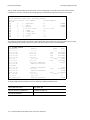
REGULATORY COMPLIANCE STATEMENTS
Note
Complies with Part 68, FCC rules.
FCC Registration Number 6TGUSA-46505-DE-N
Riverstone Networks, Inc.
Model WICT1-12
Made in U.S.A.
FCC COMPLIANCE STATEMENT
(
)!'3##*2)*B'.
?A
* '*'?A
*)'
*' **)
Note
This equipment has been tested and found to comply with the limits for a Class A
digital device, pursuant to Part 15 of the FCC rules. These limits are designed to
provide reasonable protection against harmful interference when the equipment is
operated in a commercial environment. This equipment uses, generates, and can
radiate radio frequency energy and if not installed in accordance with the
operator’s manual, may cause harmful interference to radio communications.
Operation of this equipment in a residential area is likely to cause interference in
which case the user will be required to correct the interference at his own expense.
Riverstone Networks RS Switch Router User Guide Release 8.0 iii
Warning
Changes or modifications made to this device that are not expressly approved
by the party responsible for compliance could void the user’s authority to
operate the equipment.
INDUSTRY CANADA COMPLIANCE STATEMENT
())*H# ' ' ))*
*'*'#7) '#
*
=)I))* IJ*KI )*IJ*I) ))*H
))* IJ*)L **IJ*II
) L#
**#
(*#''J*) (' J*) *)
)'J* ))))( 5J*) (J* * ?A() *J*) )*K'
+'J*) ***) '
'
* )(J*) **)
'(* * )
)
'
*
)'J*) *)
*))
) *J*) J*) '* * )*J**J*) &**')*')*
) )) ')(
)* )* )*
&* ) * **
))))*)))
(5J*
* ?5A )
' H * * ' )'( ' ' '
*BJ* * '
5J*
* '
H
iv Riverstone Networks RS Switch Router User Guide Release 8.0
VCCI COMPLIANCE STATEMENT
(#)*'6*##*''
' (5J*) ?6##A'J*) * * 4**** J*
SAFETY INFORMATION: CLASS 1 LASER TRANSCEIVERS
!"#""$"
(#
*)') #) (
) ' B* (*)*'
*B* #
)''.
• 21 CFR 1040.10 and 1040.11, U.S. Department of Health and Human Services (FDA)
•
•
IEC Publication 825 (International Electrotechnical Commission)
CENELEC EN 60825 (European Committee for Electrotechnical Standardization)
4))' *)* #
'#
'M*
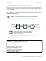
LASER RADIATION AND CONNECTORS
4) '( H * *'
)H'?* A-D+ HFD
)' ' ))( H * ' ))?*AE 4 FE
H04 -
# "
#
% &#
'#$"
#
Riverstone Networks RS Switch Router User Guide Release 8.0 v
SAFETY INFORMATION: WICT1-12 T1 CARD
Warning
(*''*D4
*
CONSUMER INFORMATION AND FCC REQUIREMENTS
1.
This equipment complies with Part 68 of the FCC rules, FCC Registration Number
6TGUSA-46505-DE-N Riverstone Networks Inc. Model WICT1-12 Made in the USA. On the
DS1/E1 WAN Module of this equipment is a label that contains, among other information, the FCC
registration number and Ringer Equivalence Number (REN) for this equipment. If requested,
provide this information to your telephone company.
2.
The REN is useful to determine the quantity of devices you may connect to your telephone and still
have all those devices ring when your number is called. In most, but not all areas, the sum of the
REN's of all devices should not exceed five (5.0). To be certain of the number of devices you may
connect to your line, as determined by the REN, you should call your local telephone company to
determine the maximum REN for your calling area.
3.
If your DS1/E1 WAN Module causes harm to the telephone network, the Telephone Company may
discontinue your service temporarily. If possible, they will notify you in advance. But if advance
notice isn't practical, you will be notified as soon as possible. You will be advised of your right to
file a complaint with the FCC.
4.
Your telephone company may make changes in its facilities, equipment, operations, or procedures
that could affect the proper operation of your equipment. If they do, you will be given advance
notice so as to give you an opportunity to maintain uninterrupted service.
5.
If you experience trouble with this equipment DS1/E1 WAN Module, please contact Riverstone
Networks Inc., 5200 Great America Parkway, Santa Clara, CA 95054, 408 878-6500, for
repair/warranty information. The Telephone Company may ask you to disconnect this equipment
from the network until the problem has been corrected or you are sure that the equipment is not
malfunctioning.
6.
There are no repairs that can be made by the customer to the DS1/E1 WAN Module.
7.
This equipment may not be used on coin service provided by the Telephone Company. Connection
to party lines is subject to state tariffs. (Contact your state public utility commission or corporation
commission for information).
EQUIPMENT ATTACHMENT LIMITATIONS NOTICE
(*#''J*) (' J*) *)
)'J* )
)))( 5J*) (J* * ?A(7) *J*) )*N'
+'J*) ***) '
'
* )(J*) **)
'(* * )
)
'
*
vi Riverstone Networks RS Switch Router User Guide Release 8.0
)'J*) *)
*))
) *J*) J*) '* * )*J**J*) &**')*')*
) )) ')()*
)* )*
#*.&* ) **)))
)*)))
2(#5.(5J*
* ?5A )
' H * * ' )'( ' ' '
*BJ* * '
5J*
* '
H
Riverstone Networks RS Switch Router User Guide Release 8.0 vii
RIVERSTONE NETWORKS, INC.
STANDARD SOFTWARE LICENSE AGREEMENT
IMPORTANT: BEFORE UTILIZING THE PRODUCT, CAREFULLY READ THIS LICENSE
AGREEMENT.
This document is a legal agreement ("Agreement") between You, the end user, and Riverstone Networks, Inc. ("Riverstone"). BY
USING THE ENCLOSED SOFTWARE PRODUCT, YOU ARE AGREEING TO BE BOUND BY THE TERMS AND CONDITIONS OF THIS AGREEMENT AND THE RIVERSTONE STANDARD LIMITED WARRANTY, WHICH IS INCORPORATED HEREIN BY REFERENCE. IF YOU DO NOT AGREE TO THE TERMS OF THIS AGREEMENT, RETURN THE
UNOPENED LICENSED MATERIALS, ALONG WITH THE HARDWARE PURCHASED IF PROVIDED ON SUCH HARDWARE, AND PROOF OF PAYMENT TO RIVERSTONE OR YOUR DEALER, IF ANY, WITHIN THIRTY (30) DAYS FROM
THE DATE OF PURCHASE FOR A FULL REFUND.
The parties further agree that this Agreement is between You and Riverstone, and creates no obligations to You on the part of Riverstone's affiliates, subcontractors, or suppliers. You expressly relinquish any rights as a third party beneficiary to any agreements
between Riverstone and such parties, and waive any and all rights or claims against any such third party.
1.
2.
3.
4.
GRANT OF SOFTWARE LICENSE. Subject to the terms and conditions of this Agreement, Riverstone grants You the right
on a non-exclusive, basis for internal purposes only and only as expressly permitted by this Agreement
a. to use the enclosed software program (the "Licensed Software") in object code form on a single processing unit owned or
leased by You or otherwise use the software as embedded in equipment provided by Riverstone;
b. to use the Licensed Software on any replacement for that processing unit or equipment;
c. to use any related documentation (collectively with the Licensed Software the "Licensed Materials"), provided that You
may not copy the documentation;
d. to make copies of the Licensed Software in only the amount necessary for backup or archival purposes, or to replace a
defective copy; provided that You (i) have not more than two (2) total copies of the Licensed Software including the
original media without Riverstone's prior written consent, (ii) You operate no more than one copy of the Licensed
Software, (iii) and You retain all copyright, trademark and other proprietary notices on the copy.
RESTRICTION AGAINST COPYING OR MODIFYING LICENSED MATERIALS. All rights not expressly granted
herein are reserved by Riverstone or its suppliers or licensors. Without limiting the foregoing, You agree
a. to maintain appropriate records of the location of the original media and all copies of the Licensed Software, in whole or
in part, made by You;
b. not to use, copy or modify the Licensed Materials, in whole or in part, except as expressly provided in this Agreement;
c. not to decompile, disassemble, electronically transfer, or reverse engineer the Licensed Software, or to translate the
Licensed Software into another computer language; provided that, if You are located within a Member State of the
European community, then such activities shall be permitted solely to the extent, if any, permitted under Article 6 of the
Council Directive of 14 May 1991 on the legal protection of computer programs, and implementing legislations
thereunder.
TERM AND TRANSFER. You may transfer the License Materials with a copy of this Agreement to another party only on
a permanent basis in connection with the transfer to the same party of the equipment on which it is used, and only if the other
party accepts the terms and conditions of this Agreement. Upon such transfer, You must transfer all accompanying written
materials, and either transfer or destroy all copies of the Software. Any attempted transfer not permitted by this Agreement is
void. You may not lease or rent the License Materials. This Agreement is effective until terminated. You may terminate the
Agreement at any time by destroying or purging all copies of the Licensed Materials. This Agreement will terminate
automatically without notice from Riverstone if You fail to comply with any provision of this Agreement. Upon such
termination, You must destroy the Licensed Materials as set forth above. Sections 4, 5, 6, 7, 8, 9, and 10 shall survive
termination of this Agreement for any reason.
TITLE AND PROPRIETARY RIGHTS.
(a) The Licensed Materials are copyrighted works and/or trade secrets of Riverstone and are the sole and exclusive property
of Riverstone, any company or a division thereof which Riverstone controls or is controlled by, or which may result from
the merger or consolidation with Riverstone (its "Affiliates"), and/or their suppliers. This Agreement conveys a limited
right to operate the Licensed Materials and shall not be construed to convey title to the Licensed Materials to You.
(b) You acknowledge that in the event of a breach of this Agreement, Riverstone shall suffer severe and irreparable damages
for which monetary compensation alone will be inadequate. You agree that in the event of a breach of this Agreement,
Riverstone shall be entitled to monetary damages and its reasonable attorney's fees and costs in enforcing this Agreement,
as well as injunctive relief to restrain such breach, in addition to any other remedies available to Riverstone.
viii Riverstone Networks RS Switch Router User Guide Release 8.0
5.
MAINTENANCE AND UPDATES. Updates, upgrades, bug fixes, and maintenance and support services, if any, are
provided to You pursuant to the terms of a Riverstone Service and Maintenance Agreement, and only if Riverstone and You
enter into such an agreement. Except as specifically set forth in such agreement, Riverstone is under no obligation to provide
any updates, upgrades, patches, bug fixes, modifications, enhancements, or maintenance or support services to You.
Notwithstanding the foregoing, if you are provided or obtain any software or documentation of Riverstone, which is not
otherwise provided under a license from Riverstone, then Your use of such materials shall be subject to the terms of this
Riverstone Networks, Inc. Software License Agreement.
6.
EXPORT REQUIREMENTS. Licensed Software, including technical data, is subject to U.S. export control laws, including
the U.S. Export Administration Act and its associated regulations, and may be subject to export or import regulations in other
countries. You agree to comply strictly with all such regulations and acknowledge that you have the responsibility to obtain
licenses to export, re-export or import Licensed Materials.
7.
UNITED STATES GOVERNMENT RESTRICTED RIGHTS. The Licensed Materials are provided with RESTRICTED
RIGHTS. Use, duplication or disclosure of the Licensed Materials and accompanying documentation by the U.S. Government
is subject to restrictions as set forth in this Agreement and as provided in DFARS 227.7202-1(a) and 227.7202-3(a) (1995),
DRAS 252.227-7013(c)(ii) (OCT 1988), FAR 12.212(a)(1995), FAR 52.227-19, or FAR 52.227-14 (ALT III), as applicable.
Riverstone Networks, Inc.
8.
LIMITED WARRANTY. The sole warranty provided under this Agreement and with respect to the Licensed Materials is set
forth in Riverstone's Standard Limited Warranty, which is incorporated herein by reference. THE RIVERSTONE
STANDARD LIMITED WARRANTY CONTAINS IMPORTANT LIMITS ON YOUR WARRANTY RIGHTS. THE
WARRANTIES AND LIABILITIES SET FORTH IN THE STANDARD LIMITED WARRANTY ARE EXCLUSIVE AND
ESTABLISH RIVERSTONE'S ONLY OBLIGATIONS AND YOUR SOLE RIGHTS WITH RESPECT TO THE LICENSED
MATERIALS AND THIS AGREEMENT. ALL EXPRESS OR IMPLIED CONDITIONS, REPRESENTATIONS AND
WARRANTIES INCLUDING, WITHOUT LIMITATION, ANY IMPLIED WARRANTIES OR CONDITIONS OF
MERCHANTABILITY, FITNESS FOR A PARTICULAR PURPOSE, SATISFACTORY QUALITY, NONINFRINGEMENT
OR ARISING FROM A COURSE OF DEALING, USAGE, OR TRADE PRACTICE, ARE HEREBY EXCLUDED TO THE
EXTENT ALLOWED BY APPLICABLE LAW.
9.
LIMITATION OF LIABILITY. Your exclusive remedy for any claim in connection with the Licensed Materials and the
entire liability of Riverstone are set forth in the Riverstone Standard Limited Warranty. Except to the extent provided there, if
any, IN NO EVENT WILL RIVERSTONE OR ITS AFFILIATES OR SUPPLIERS BE LIABLE FOR ANY LOSS OF USE,
INTERRUPTION OF BUSINESS, LOST PROFITS OR LOST DATA, OR ANY INDIRECT, SPECIAL, INCIDENTAL, OR
CONSEQUENTIAL DAMAGES OF ANY KIND, REGARDLESS OF THE FORM OF ACTION, WHETHER IN
CONTRACT, TORT (INCLUDING NEGLIGENCE), STRICT LIABILITY OR OTHERWISE, EVEN IF RIVERSTONE OR
ITS AFFILIATE OR SUPPLIER HAS BEEN ADVISED OF THE POSSIBILITY OF SUCH DAMAGE, AND WHETHER
OR NOT ANY REMEDY PROVIDED SHOULD FAIL OF ITS ESSENTIAL PURPOSE. THE TOTAL CUMULATIVE
LIABILITY TO YOU, FROM ALL CAUSES OF ACTION AND ALL THEORIES OF LIABILITY, WILL BE LIMITED TO
AND WILL NOT EXCEED THE PURCHASE PRICE OF THE LICENSED MATERIALS PAID BY YOU. YOU
ACKNOWLEDGE THAT THE AMOUNT PAID FOR THE LICENSED MATERIALS REFLECTS THIS ALLOCATION
OF RISK.
10. GENERAL. The provisions of the Agreement are severable and if any one or more of the provisions hereof are illegal or
otherwise unenforceable, in whole or in part, the remaining provisions of this Agreement shall nevertheless be binding on and
enforceable by and between the parties hereto. Riverstone's waiver of any right shall not constitute waiver of that right in
future. This Agreement (including the documents it incorporates) constitutes the entire understanding between the parties with
respect to the subject matter hereof, and all prior agreements, representations, statements and undertakings, oral or written, are
hereby expressly superseded and canceled. No purchase order shall supersede this Agreement. The rights and obligations of
the parties to this Agreement shall be governed and construed in accordance with the laws of the State of California, excluding
the UN Convention on Contracts for the International Sale of Goods and that body of law known as conflicts of laws. Any
dispute in connection with the Licensed Materials will be resolved in state or federal courts located in Santa Clara County,
California, U.S.A.. You consent to the personal jurisdiction of and waive any objections to venue in such courts.
Riverstone Networks RS Switch Router User Guide Release 8.0 ix
STANDARD LIMITED WARRANTY
Limited Warranty
Riverstone Networks, Inc. (“Riverstone”) warrants that for a period of one (1) year from the date of shipment from
Riverstone that the Riverstone hardware purchased by Customer (“Hardware”) will be free from defects in materials
and workmanship under normal use. This limited warranty extends only to Customer as original purchaser. Customer’s sole and exclusive remedy and the entire liability of Riverstone, its suppliers and affiliates under this warranty is, at Riverstone’s option, either (i) repair of the Hardware, (ii) replacement of the Hardware, or (iii) refund of
the purchase price of the Hardware (as evidenced by a copy of Customer’s purchase receipt), less any rebates or credits.
Riverstone warrants that for a period of one (1) year from the date of shipment from Riverstone that the media on
which the Riverstone software purchased by Customer (“Software”) is furnished will be free from defects in materials and workmanship under normal use. This limited warranty extends only to Customer as original licensee. Customer’s sole and exclusive remedy and the entire liability of Riverstone, its suppliers and affiliates under this
warranty is replacement of the media on which the Software is furnished. Riverstone makes no warranty with respect
to the Software, and specifically disclaims any warranty that the Software is error free or that Customer will be able
to operate the Software without problems or interruptions.
Restrictions. No warranty will apply if the Hardware and/or Software (collectively, “Product”) (i) has been altered,
except by Riverstone; (ii) has not been installed, operated, repaired, or maintained in accordance with instructions
supplied by Riverstone; or (iii) has been subjected to abnormal physical, thermal or electrical stress, misuse, negligence, or accident. In addition, Products are not designed or intended for use in (i) the design, construction, operation
or maintenance of any nuclear facility, (ii) navigating or operating aircraft; or (iii) operating life-support or life-critical medical equipment, and Riverstone disclaims any express or implied warranty of fitness for such uses.
Warranty Service Procedures
Customer must notify Riverstone of any defect in the Product within the applicable warranty period and provide
dated proof of original purchase prior to the return of any defective Product. Within ten (10) business days of the date
of notification, Riverstone will provide Customer with a Return Material Authorization (“RMA”) number and the
location to which Customer must return the defective Product. Customer is responsible for proper packaging of Product returned to Riverstone, including description of the failure, shipment to Riverstone’s designated location, and
return of Product within ten (10) days after issuance of the RMA number. In no event will Riverstone accept any
returned Product which does not have a valid RMA number. Customer’s failure to return Product within thirty (30)
days of its receipt of an RMA may result in cancellation of the RMA and/or the charge of the list price of any
advanced replacement product. Riverstone does not accept responsibility for any Product lost in transit and recommends that the return be insured for the full value. Riverstone will use all reasonable efforts within thirty (30) days of
receipt of defective Product to repair or replace such Product or refund Customer’s purchase price.
Transportation costs relating to warranty service and any applicable duties will be borne by Customer. If a warranty
claim is invalid for any reason, Customer will be charged at Riverstone’s then-current standard rates for services performed and will be charged for all expenses incurred by Riverstone.
Replacement Products or replacement parts used in the repair of Products may be new or reconditioned.
Riverstone shall not be responsible for Customer’s or any third party’s software, firmware, information, or memory
x Riverstone Networks RS Switch Router User Guide Release 8.0
data contained in, sorted on, or integrated with any Product returned to Riverstone, whether under warranty or not.
Customer is responsible for backing up its programs and data to protect against loss or corruption.
Disclaimer. EXCEPT AS SPECIFIED ABOVE, ALL EXPRESS OR IMPLIED CONDITIONS, REPRESENTATIONS AND WARRANTIES INCLUDING, WITHOUT LIMITATION, ANY IMPLIED WARRANTIES OR CONDITIONS OF MERCHANTABILITY, FITNESS FOR A PARTICULAR PURPOSE, SATISFACTORY QUALITY,
NONINFRINGEMENT OR ARISING FROM A COURSE OF DEALING, USAGE, OR TRADE PRACTICE, ARE
HEREBY EXCLUDED TO THE EXTENT ALLOWED BY APPLICABLE LAW.
Limitation of Liability. IN NO EVENT WILL RIVERSTONE OR ITS AFFILIATES OR SUPPLIERS BE LIABLE
FOR ANY LOSS OF USE, INTERRUPTION OF BUSINESS, LOST PROFITS, OR LOST DATA, OR INDIRECT,
SPECIAL, INCIDENTAL, OR CONSEQUENTIAL DAMAGES, OF ANY KIND REGARDLESS OF THE FORM
OF ACTION, WHETHER IN CONTRACT, TORT (INCLUDING NEGLIGENCE), STRICT LIABILITY OR OTHERWISE, EVEN IF RIVERSTONE OR ITS AFFILIATE OR SUPPLIER HAS BEEN ADVISED OF THE POSSIBILITY OF SUCH DAMAGE, AND WHETHER OR NOT ANY REMEDY PROVIDED SHOULD FAIL OF ITS
ESSENTIAL PURPOSE. THE TOTAL CUMULATIVE LIABILITY TO CUSTOMER, FROM ALL CAUSES OF
ACTION AND ALL THEORIES OF LIABILITY, WILL BE LIMITED TO AND WILL NOT EXCEED THE PURCHASE PRICE OF THE PRODUCT PAID BY CUSTOMER.
Riverstone Networks RS Switch Router User Guide Release 8.0 xi
DECLARATION OF CONFORMITY ADDENDUM
"
()
E$/00D/55#
,0/0/55#
*"
+
*"
+
!
"##$%
"
(),-
.
5#7
E$/00D/55#
5#7
,0/0/55#
5
5EF
5D$
/,
J*) '*
F*
xii Riverstone Networks RS Switch Router User Guide Release 8.0
TABLE OF CONTENTS
1
Introduction. . . . . . . . . . . . . . . . . . . . . . . . . . . . . . . . . . . . . . . . . . . . . . . . . . 1-1
1.1
Related Documentation . . . . . . . . . . . . . . . . . . . . . . . . . . . . . . . . . . . . . . . . . . . . . . . . . . . . . . . . . . . . . 1-1
1.2
Document Conventions . . . . . . . . . . . . . . . . . . . . . . . . . . . . . . . . . . . . . . . . . . . . . . . . . . . . . . . . . . . . . 1-2
2
Maintaining Configuration Files . . . . . . . . . . . . . . . . . . . . . . . . . . . . . . . . . . 2-1
2.1
2.1.1
2.1.2
2.1.3
2.1.4
2.1.5
2.1.6
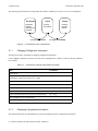
Configuration Files . . . . . . . . . . . . . . . . . . . . . . . . . . . . . . . . . . . . . . . . . . . . . . . . . . . . . . . . . . . . . . . . 2-1
Changing Configuration Information. . . . . . . . . . . . . . . . . . . . . . . . . . . . . . . . . . . . . . . . . . . . . . . 2-2
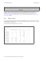
Displaying Configuration Information. . . . . . . . . . . . . . . . . . . . . . . . . . . . . . . . . . . . . . . . . . . . . . 2-2
Activating the Configuration Commands in the Scratchpad . . . . . . . . . . . . . . . . . . . . . . . . . . . . . 2-3
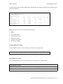
Saving the Active Configuration to the Startup Configuration File . . . . . . . . . . . . . . . . . . . . . . . 2-4
Viewing the Current Configuration . . . . . . . . . . . . . . . . . . . . . . . . . . . . . . . . . . . . . . . . . . . . . . . . 2-4
Backing Up and Restoring Configuration Files . . . . . . . . . . . . . . . . . . . . . . . . . . . . . . . . . . . . . . . 2-5
2.2
Backing Up and Restoring System Image Files . . . . . . . . . . . . . . . . . . . . . . . . . . . . . . . . . . . . . . . . . . 2-6
2.3
2.3.1
2.3.2
Configuring System Settings. . . . . . . . . . . . . . . . . . . . . . . . . . . . . . . . . . . . . . . . . . . . . . . . . . . . . . . . . 2-7
Setting Daylight Saving Time . . . . . . . . . . . . . . . . . . . . . . . . . . . . . . . . . . . . . . . . . . . . . . . . . . . . 2-8
Configuring a Log-in Banner . . . . . . . . . . . . . . . . . . . . . . . . . . . . . . . . . . . . . . . . . . . . . . . . . . . . . 2-8
3
CLI and RS Basics . . . . . . . . . . . . . . . . . . . . . . . . . . . . . . . . . . . . . . . . . . . . 3-1
3.1
Starting the CLI . . . . . . . . . . . . . . . . . . . . . . . . . . . . . . . . . . . . . . . . . . . . . . . . . . . . . . . . . . . . . . . . . . . 3-1
3.2
3.2.1
3.2.2
3.2.3
3.2.4
Understanding CLI Command Modes . . . . . . . . . . . . . . . . . . . . . . . . . . . . . . . . . . . . . . . . . . . . . . . . . 3-2
User Mode . . . . . . . . . . . . . . . . . . . . . . . . . . . . . . . . . . . . . . . . . . . . . . . . . . . . . . . . . . . . . . . . . . . 3-2
Enable Mode . . . . . . . . . . . . . . . . . . . . . . . . . . . . . . . . . . . . . . . . . . . . . . . . . . . . . . . . . . . . . . . . . 3-2
Configure Mode . . . . . . . . . . . . . . . . . . . . . . . . . . . . . . . . . . . . . . . . . . . . . . . . . . . . . . . . . . . . . . . 3-3
BootPROM Mode . . . . . . . . . . . . . . . . . . . . . . . . . . . . . . . . . . . . . . . . . . . . . . . . . . . . . . . . . . . . . 3-3
3.3
Understanding CLI Commands. . . . . . . . . . . . . . . . . . . . . . . . . . . . . . . . . . . . . . . . . . . . . . . . . . . . . . . 3-3
3.4
Using Line Editing Commands . . . . . . . . . . . . . . . . . . . . . . . . . . . . . . . . . . . . . . . . . . . . . . . . . . . . . . . 3-4
3.5
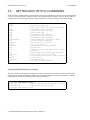
Getting Help with CLI Commands . . . . . . . . . . . . . . . . . . . . . . . . . . . . . . . . . . . . . . . . . . . . . . . . . . . . 3-6
3.6
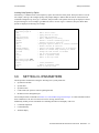
Setting CLI Parameters . . . . . . . . . . . . . . . . . . . . . . . . . . . . . . . . . . . . . . . . . . . . . . . . . . . . . . . . . . . . . 3-7
3.7
3.7.1
3.7.2
3.7.3
3.7.4
3.7.5
3.7.6
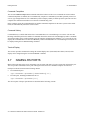
Naming RS Ports. . . . . . . . . . . . . . . . . . . . . . . . . . . . . . . . . . . . . . . . . . . . . . . . . . . . . . . . . . . . . . . . . . 3-8
Port Type . . . . . . . . . . . . . . . . . . . . . . . . . . . . . . . . . . . . . . . . . . . . . . . . . . . . . . . . . . . . . . . . . . . . 3-9
Slot Number . . . . . . . . . . . . . . . . . . . . . . . . . . . . . . . . . . . . . . . . . . . . . . . . . . . . . . . . . . . . . . . . . . 3-9
Port Number . . . . . . . . . . . . . . . . . . . . . . . . . . . . . . . . . . . . . . . . . . . . . . . . . . . . . . . . . . . . . . . . . . 3-9
Channel Number . . . . . . . . . . . . . . . . . . . . . . . . . . . . . . . . . . . . . . . . . . . . . . . . . . . . . . . . . . . . . 3-11
VC . . . . . . . . . . . . . . . . . . . . . . . . . . . . . . . . . . . . . . . . . . . . . . . . . . . . . . . . . . . . . . . . . . . . . . . . 3-12
Port Name Example . . . . . . . . . . . . . . . . . . . . . . . . . . . . . . . . . . . . . . . . . . . . . . . . . . . . . . . . . . . 3-12
3.8
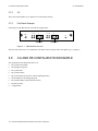
CLI and RS Configuration Example . . . . . . . . . . . . . . . . . . . . . . . . . . . . . . . . . . . . . . . . . . . . . . . . . . 3-12
Riverstone Networks RS Switch Router User Guide Release 8.0 xiii
4
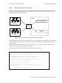
Hot Swapping Line Cards and Control Modules . . . . . . . . . . . . . . . . . . . . . . 4-1
4.1
Hot Swapping Overview . . . . . . . . . . . . . . . . . . . . . . . . . . . . . . . . . . . . . . . . . . . . . . . . . . . . . . . . . . . . 4-1
4.2
4.2.1
4.2.2
4.2.3
Hot Swapping Line Cards . . . . . . . . . . . . . . . . . . . . . . . . . . . . . . . . . . . . . . . . . . . . . . . . . . . . . . . . . . . 4-1
Deactivating the Line Card. . . . . . . . . . . . . . . . . . . . . . . . . . . . . . . . . . . . . . . . . . . . . . . . . . . . . . . 4-2
Removing the Line Card . . . . . . . . . . . . . . . . . . . . . . . . . . . . . . . . . . . . . . . . . . . . . . . . . . . . . . . . 4-2
Installing a New Line Card. . . . . . . . . . . . . . . . . . . . . . . . . . . . . . . . . . . . . . . . . . . . . . . . . . . . . . . 4-3
4.3
Hot Swapping One Type of Line Card With Another. . . . . . . . . . . . . . . . . . . . . . . . . . . . . . . . . . . . . . 4-3
4.4
4.4.1
4.4.2
4.4.3
Hot Swapping a Secondary Control Module . . . . . . . . . . . . . . . . . . . . . . . . . . . . . . . . . . . . . . . . . . . . . 4-3
Deactivating the Control Module . . . . . . . . . . . . . . . . . . . . . . . . . . . . . . . . . . . . . . . . . . . . . . . . . . 4-4
Removing the Control Module. . . . . . . . . . . . . . . . . . . . . . . . . . . . . . . . . . . . . . . . . . . . . . . . . . . . 4-5
Installing a Control Module . . . . . . . . . . . . . . . . . . . . . . . . . . . . . . . . . . . . . . . . . . . . . . . . . . . . . . 4-5
4.5
4.5.1
4.5.2
Hot Swapping a Switching Fabric Module (RS 8600 only) . . . . . . . . . . . . . . . . . . . . . . . . . . . . . . . . . 4-5
Removing the Switching Fabric Module . . . . . . . . . . . . . . . . . . . . . . . . . . . . . . . . . . . . . . . . . . . . 4-6
Installing a Switching Fabric Module . . . . . . . . . . . . . . . . . . . . . . . . . . . . . . . . . . . . . . . . . . . . . . 4-6
4.6
4.6.1
4.6.2
Hot Swapping A GBIC (RS 32000 and RS 38000 only) . . . . . . . . . . . . . . . . . . . . . . . . . . . . . . . . . . . 4-7
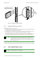
Removing a GBIC from the Line Card . . . . . . . . . . . . . . . . . . . . . . . . . . . . . . . . . . . . . . . . . . . . . 4-7
Installing a GBIC into the Line Card . . . . . . . . . . . . . . . . . . . . . . . . . . . . . . . . . . . . . . . . . . . . . . . 4-8
4.7
Hot Swapping a WIC. . . . . . . . . . . . . . . . . . . . . . . . . . . . . . . . . . . . . . . . . . . . . . . . . . . . . . . . . . . . . . . 4-8
5
Bridging Configuration Guide . . . . . . . . . . . . . . . . . . . . . . . . . . . . . . . . . . . . 5-1
5.1
Spanning Tree (IEEE 802.1d) . . . . . . . . . . . . . . . . . . . . . . . . . . . . . . . . . . . . . . . . . . . . . . . . . . . . . . . . 5-1
5.2
Bridging Modes (Flow-Based and Address-Based) . . . . . . . . . . . . . . . . . . . . . . . . . . . . . . . . . . . . . . . 5-1
5.3
5.3.1
5.3.2
VLAN Overview . . . . . . . . . . . . . . . . . . . . . . . . . . . . . . . . . . . . . . . . . . . . . . . . . . . . . . . . . . . . . . . . . . 5-2
RS VLAN Support . . . . . . . . . . . . . . . . . . . . . . . . . . . . . . . . . . . . . . . . . . . . . . . . . . . . . . . . . . . . . 5-3
Configuration Examples. . . . . . . . . . . . . . . . . . . . . . . . . . . . . . . . . . . . . . . . . . . . . . . . . . . . . . . . . 5-4
5.4
Access Ports and Trunk Ports (802.1P and 802.1Q support) . . . . . . . . . . . . . . . . . . . . . . . . . . . . . . . . 5-5
5.5
5.5.1
Configuring RS Bridging Functions . . . . . . . . . . . . . . . . . . . . . . . . . . . . . . . . . . . . . . . . . . . . . . . . . . . 5-6
Configuring Address-based or Flow-based Bridging. . . . . . . . . . . . . . . . . . . . . . . . . . . . . . . . . . . 5-6
5.6
5.6.1
5.6.2
5.6.3
Configuring Spanning Tree . . . . . . . . . . . . . . . . . . . . . . . . . . . . . . . . . . . . . . . . . . . . . . . . . . . . . . . . . . 5-7
Using Rapid STP . . . . . . . . . . . . . . . . . . . . . . . . . . . . . . . . . . . . . . . . . . . . . . . . . . . . . . . . . . . . . . 5-7
Adjusting Spanning-Tree Parameters. . . . . . . . . . . . . . . . . . . . . . . . . . . . . . . . . . . . . . . . . . . . . . . 5-8
STP Dampening . . . . . . . . . . . . . . . . . . . . . . . . . . . . . . . . . . . . . . . . . . . . . . . . . . . . . . . . . . . . . . 5-11
5.7
5.7.1
5.7.2
5.7.3
Configuring a Port- or Protocol-Based VLAN . . . . . . . . . . . . . . . . . . . . . . . . . . . . . . . . . . . . . . . . . . 5-11
Creating a Port or Protocol Based VLAN . . . . . . . . . . . . . . . . . . . . . . . . . . . . . . . . . . . . . . . . . . 5-12
Adding Ports to a VLAN . . . . . . . . . . . . . . . . . . . . . . . . . . . . . . . . . . . . . . . . . . . . . . . . . . . . . . . 5-12
Configuring VLAN Trunk Ports . . . . . . . . . . . . . . . . . . . . . . . . . . . . . . . . . . . . . . . . . . . . . . . . . 5-12
5.8
Configuring VLANs for Bridging . . . . . . . . . . . . . . . . . . . . . . . . . . . . . . . . . . . . . . . . . . . . . . . . . . . . 5-13
5.9
Configuring Layer-2 Filters. . . . . . . . . . . . . . . . . . . . . . . . . . . . . . . . . . . . . . . . . . . . . . . . . . . . . . . . . 5-13
5.10
Monitoring Bridging . . . . . . . . . . . . . . . . . . . . . . . . . . . . . . . . . . . . . . . . . . . . . . . . . . . . . . . . . . . . . . 5-14
5.11
5.11.1
5.11.2
5.11.3
GARP/GVRP. . . . . . . . . . . . . . . . . . . . . . . . . . . . . . . . . . . . . . . . . . . . . . . . . . . . . . . . . . . . . . . . . . . . 5-15
Running GARP/GVRP with STP. . . . . . . . . . . . . . . . . . . . . . . . . . . . . . . . . . . . . . . . . . . . . . . . . 5-15
Configuring GARP/GVRP . . . . . . . . . . . . . . . . . . . . . . . . . . . . . . . . . . . . . . . . . . . . . . . . . . . . . . 5-16
Configuration Example . . . . . . . . . . . . . . . . . . . . . . . . . . . . . . . . . . . . . . . . . . . . . . . . . . . . . . . . 5-17
5.12
5.12.1
Tunneling VLAN packets across MANs. . . . . . . . . . . . . . . . . . . . . . . . . . . . . . . . . . . . . . . . . . . . . . . 5-19
Stackable VLAN Components . . . . . . . . . . . . . . . . . . . . . . . . . . . . . . . . . . . . . . . . . . . . . . . . . . . 5-19
xiv
Riverstone Networks RS Switch Router User Guide Release 8.0
5.12.2
5.12.3
Configuration Examples . . . . . . . . . . . . . . . . . . . . . . . . . . . . . . . . . . . . . . . . . . . . . . . . . . . . . . . 5-20
Displaying Stackable VLAN Information . . . . . . . . . . . . . . . . . . . . . . . . . . . . . . . . . . . . . . . . . . 5-35
6
SmartTRUNK Configuration Guide . . . . . . . . . . . . . . . . . . . . . . . . . . . . . . . 6-1
6.1
6.1.1
6.1.2
6.1.3
Configuring SmartTRUNKS. . . . . . . . . . . . . . . . . . . . . . . . . . . . . . . . . . . . . . . . . . . . . . . . . . . . . . . . . 6-1
Creating a SmartTRUNK. . . . . . . . . . . . . . . . . . . . . . . . . . . . . . . . . . . . . . . . . . . . . . . . . . . . . . . . 6-2
Adding Physical Ports to the SmartTRUNK . . . . . . . . . . . . . . . . . . . . . . . . . . . . . . . . . . . . . . . . . 6-2
Specifying Traffic Load Policy . . . . . . . . . . . . . . . . . . . . . . . . . . . . . . . . . . . . . . . . . . . . . . . . . . . 6-3
6.2
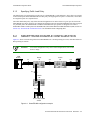
SmartTRUNK Example Configuration . . . . . . . . . . . . . . . . . . . . . . . . . . . . . . . . . . . . . . . . . . . . . . . . . 6-3
6.3
6.3.1
6.3.2
Configuring the Link Aggregation Control Protocol (LACP) . . . . . . . . . . . . . . . . . . . . . . . . . . . . . . . 6-5
Configuring SmartTRUNKs for LACP . . . . . . . . . . . . . . . . . . . . . . . . . . . . . . . . . . . . . . . . . . . . . 6-5
LACP Configuration Example. . . . . . . . . . . . . . . . . . . . . . . . . . . . . . . . . . . . . . . . . . . . . . . . . . . . 6-6
6.4
6.4.1
6.4.2
6.4.3
SmartTRUNK Load Redistribution . . . . . . . . . . . . . . . . . . . . . . . . . . . . . . . . . . . . . . . . . . . . . . . . . . . 6-9
SLR Water-marks . . . . . . . . . . . . . . . . . . . . . . . . . . . . . . . . . . . . . . . . . . . . . . . . . . . . . . . . . . . . . 6-9
Polling intervals . . . . . . . . . . . . . . . . . . . . . . . . . . . . . . . . . . . . . . . . . . . . . . . . . . . . . . . . . . . . . . . 6-9
Additional Controls Provided by SLR . . . . . . . . . . . . . . . . . . . . . . . . . . . . . . . . . . . . . . . . . . . . . 6-11
7
CMTS Configuration Guide . . . . . . . . . . . . . . . . . . . . . . . . . . . . . . . . . . . . . 7-1
7.1
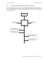
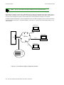
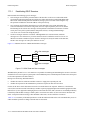
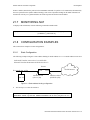
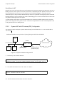
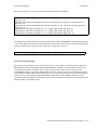
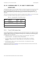
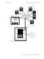
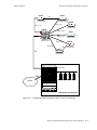
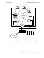
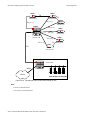
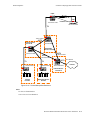
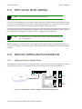
HFC Cable Network Architecture. . . . . . . . . . . . . . . . . . . . . . . . . . . . . . . . . . . . . . . . . . . . . . . . . . . . . 7-1
7.2
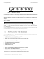
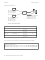
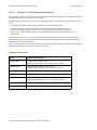
CMTS Module Description . . . . . . . . . . . . . . . . . . . . . . . . . . . . . . . . . . . . . . . . . . . . . . . . . . . . . . . . . . 7-1
7.3
7.3.1
7.3.2
7.3.3
7.3.4
7.3.5
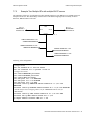
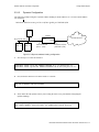
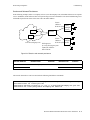
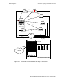
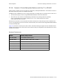
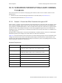
Provisioning the Headend . . . . . . . . . . . . . . . . . . . . . . . . . . . . . . . . . . . . . . . . . . . . . . . . . . . . . . . . . . . 7-2
Headend Certification . . . . . . . . . . . . . . . . . . . . . . . . . . . . . . . . . . . . . . . . . . . . . . . . . . . . . . . . . . 7-3
IF-RF-Upconverter. . . . . . . . . . . . . . . . . . . . . . . . . . . . . . . . . . . . . . . . . . . . . . . . . . . . . . . . . . . . . 7-3
Diplex Filters . . . . . . . . . . . . . . . . . . . . . . . . . . . . . . . . . . . . . . . . . . . . . . . . . . . . . . . . . . . . . . . . . 7-3
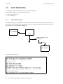
DHCP Servers . . . . . . . . . . . . . . . . . . . . . . . . . . . . . . . . . . . . . . . . . . . . . . . . . . . . . . . . . . . . . . . . 7-5
DNS and TFTP Servers . . . . . . . . . . . . . . . . . . . . . . . . . . . . . . . . . . . . . . . . . . . . . . . . . . . . . . . . . 7-5
7.4
7.4.1
7.4.2
7.4.3
7.4.4
7.4.5
7.4.6
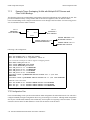
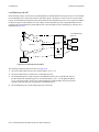
Connecting and Configuring the Downstream . . . . . . . . . . . . . . . . . . . . . . . . . . . . . . . . . . . . . . . . . . . 7-5
Installing and Configuring the Upconverter . . . . . . . . . . . . . . . . . . . . . . . . . . . . . . . . . . . . . . . . . 7-6
Setting the Upconverter Input Level . . . . . . . . . . . . . . . . . . . . . . . . . . . . . . . . . . . . . . . . . . . . . . . 7-6
Setting the Upconverter Output Level . . . . . . . . . . . . . . . . . . . . . . . . . . . . . . . . . . . . . . . . . . . . . . 7-6
Setting the Upconverter Output Frequency . . . . . . . . . . . . . . . . . . . . . . . . . . . . . . . . . . . . . . . . . . 7-6
Completing the Downstream Configuration . . . . . . . . . . . . . . . . . . . . . . . . . . . . . . . . . . . . . . . . . 7-7
Testing the Downstream Configuration . . . . . . . . . . . . . . . . . . . . . . . . . . . . . . . . . . . . . . . . . . . . . 7-7
7.5
Connecting the Upstream to the Laser Receiver . . . . . . . . . . . . . . . . . . . . . . . . . . . . . . . . . . . . . . . . . . 7-7
7.6
7.6.1
7.6.2
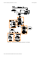
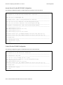
Configuring the CMTS Module . . . . . . . . . . . . . . . . . . . . . . . . . . . . . . . . . . . . . . . . . . . . . . . . . . . . . . 7-8
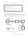
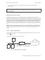
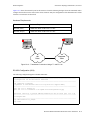
Configuring the CMTS Module in a Bridged Network . . . . . . . . . . . . . . . . . . . . . . . . . . . . . . . . . 7-8
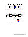
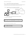
Configuring the CMTS Module in a Routed Network . . . . . . . . . . . . . . . . . . . . . . . . . . . . . . . . . 7-9
7.7
7.7.1
7.7.2
7.7.3
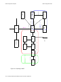
CMTS Configuration Examples . . . . . . . . . . . . . . . . . . . . . . . . . . . . . . . . . . . . . . . . . . . . . . . . . . . . . 7-10
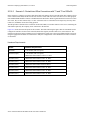
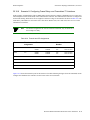
Example One: Multiple ISPs Share a Single DHCP Server . . . . . . . . . . . . . . . . . . . . . . . . . . . . 7-11
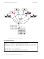
Example Two: Multiple ISPs with multiple DHCP servers . . . . . . . . . . . . . . . . . . . . . . . . . . . . 7-15
Example Three: Overlapping VLANs with Multiple DHCP Servers and
Client-VLAN Bindings7-18
7.8
7.8.1
7.8.2
Anti-Spoofing . . . . . . . . . . . . . . . . . . . . . . . . . . . . . . . . . . . . . . . . . . . . . . . . . . . . . . . . . . . . . . . . . . . 7-20
Anti-DHCP Spoofing. . . . . . . . . . . . . . . . . . . . . . . . . . . . . . . . . . . . . . . . . . . . . . . . . . . . . . . . . . 7-20
Anti-IP-spoofing . . . . . . . . . . . . . . . . . . . . . . . . . . . . . . . . . . . . . . . . . . . . . . . . . . . . . . . . . . . . . 7-21
Riverstone Networks RS Switch Router User Guide Release 8.0 xv
8
ATM Configuration Guide . . . . . . . . . . . . . . . . . . . . . . . . . . . . . . . . . . . . . . . 8-1
8.1
8.1.1
8.1.2
8.1.3
Configuring ATM Ports. . . . . . . . . . . . . . . . . . . . . . . . . . . . . . . . . . . . . . . . . . . . . . . . . . . . . . . . . . . . . 8-2
Configuring SONET Parameters . . . . . . . . . . . . . . . . . . . . . . . . . . . . . . . . . . . . . . . . . . . . . . . . . . 8-2
Setting Parameters for the Multi-Rate Line Card. . . . . . . . . . . . . . . . . . . . . . . . . . . . . . . . . . . . . . 8-3
Displaying Port Information. . . . . . . . . . . . . . . . . . . . . . . . . . . . . . . . . . . . . . . . . . . . . . . . . . . . . . 8-4
8.2
8.2.1
Configuring Virtual Channels . . . . . . . . . . . . . . . . . . . . . . . . . . . . . . . . . . . . . . . . . . . . . . . . . . . . . . . . 8-5
Gathering Traffic Statistics (OC-12) . . . . . . . . . . . . . . . . . . . . . . . . . . . . . . . . . . . . . . . . . . . . . . . 8-5
8.3
Traffic Shaping . . . . . . . . . . . . . . . . . . . . . . . . . . . . . . . . . . . . . . . . . . . . . . . . . . . . . . . . . . . . . . . . . . . 8-6
8.4
8.4.1
8.4.2
8.4.3
Traffic Management . . . . . . . . . . . . . . . . . . . . . . . . . . . . . . . . . . . . . . . . . . . . . . . . . . . . . . . . . . . . . . . 8-8
Configuring QoS (Multi-Rate Line Card) . . . . . . . . . . . . . . . . . . . . . . . . . . . . . . . . . . . . . . . . . . . 8-8
Configuring Virtual Channel Groups (OC-12). . . . . . . . . . . . . . . . . . . . . . . . . . . . . . . . . . . . . . . . 8-9
Traffic Management Configuration Example . . . . . . . . . . . . . . . . . . . . . . . . . . . . . . . . . . . . . . . 8-10
8.5
8.5.1
8.5.2
8.5.3
Bridging ATM Traffic . . . . . . . . . . . . . . . . . . . . . . . . . . . . . . . . . . . . . . . . . . . . . . . . . . . . . . . . . . . . . 8-15
Enabling Forced Bridging on a Virtual Channel . . . . . . . . . . . . . . . . . . . . . . . . . . . . . . . . . . . . . 8-17
Configuring Cross-Connects . . . . . . . . . . . . . . . . . . . . . . . . . . . . . . . . . . . . . . . . . . . . . . . . . . . . 8-17
Limiting MAC Addresses Learned on a VC . . . . . . . . . . . . . . . . . . . . . . . . . . . . . . . . . . . . . . . . 8-18
8.6
8.6.1
Routing ATM Traffic . . . . . . . . . . . . . . . . . . . . . . . . . . . . . . . . . . . . . . . . . . . . . . . . . . . . . . . . . . . . . 8-18
Peer Address Mapping . . . . . . . . . . . . . . . . . . . . . . . . . . . . . . . . . . . . . . . . . . . . . . . . . . . . . . . . . 8-21
8.7
Configuring PPP (OC-12) . . . . . . . . . . . . . . . . . . . . . . . . . . . . . . . . . . . . . . . . . . . . . . . . . . . . . . . . . . 8-23
9
Packet-over-SONET Configuration Guide . . . . . . . . . . . . . . . . . . . . . . . . . . 9-1
9.1
Configuring IP Interfaces for PoS Links . . . . . . . . . . . . . . . . . . . . . . . . . . . . . . . . . . . . . . . . . . . . . . . . 9-1
9.2
Configuring Packet-over-SONET Links . . . . . . . . . . . . . . . . . . . . . . . . . . . . . . . . . . . . . . . . . . . . . . . . 9-2
9.3
9.3.1
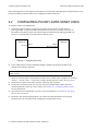
Configuring Automatic Protection Switching . . . . . . . . . . . . . . . . . . . . . . . . . . . . . . . . . . . . . . . . . . . . 9-3
Configuring Working and Protecting Ports . . . . . . . . . . . . . . . . . . . . . . . . . . . . . . . . . . . . . . . . . . 9-4
9.4
Specifying Bit Error Rate Thresholds . . . . . . . . . . . . . . . . . . . . . . . . . . . . . . . . . . . . . . . . . . . . . . . . . . 9-5
9.5
Monitoring PoS Ports . . . . . . . . . . . . . . . . . . . . . . . . . . . . . . . . . . . . . . . . . . . . . . . . . . . . . . . . . . . . . . 9-6
9.6
9.6.1
9.6.2
9.6.3
9.6.4
9.6.5
Example Configurations . . . . . . . . . . . . . . . . . . . . . . . . . . . . . . . . . . . . . . . . . . . . . . . . . . . . . . . . . . . . 9-6
APS PoS Links Between RS’s . . . . . . . . . . . . . . . . . . . . . . . . . . . . . . . . . . . . . . . . . . . . . . . . . . . . 9-7
PoS Link Between the RS and a Cisco Router. . . . . . . . . . . . . . . . . . . . . . . . . . . . . . . . . . . . . . . . 9-7
PoS Link Between the RS and a Juniper Router . . . . . . . . . . . . . . . . . . . . . . . . . . . . . . . . . . . . . . 9-8
Bridging and Routing Traffic Over a PoS Link . . . . . . . . . . . . . . . . . . . . . . . . . . . . . . . . . . . . . . . 9-9
PoS Link Through a Layer 2 Cloud . . . . . . . . . . . . . . . . . . . . . . . . . . . . . . . . . . . . . . . . . . . . . . . . 9-9
10
DHCP Configuration Guide . . . . . . . . . . . . . . . . . . . . . . . . . . . . . . . . . . . . .10-1
10.1
10.1.1
10.1.2
10.1.3
10.1.4
10.1.5
Configuring DHCP . . . . . . . . . . . . . . . . . . . . . . . . . . . . . . . . . . . . . . . . . . . . . . . . . . . . . . . . . . . . . . . 10-1
Configuring an IP Address Pool. . . . . . . . . . . . . . . . . . . . . . . . . . . . . . . . . . . . . . . . . . . . . . . . . . 10-2
Configuring Client Parameters . . . . . . . . . . . . . . . . . . . . . . . . . . . . . . . . . . . . . . . . . . . . . . . . . . . 10-2
Configuring a Static IP Address . . . . . . . . . . . . . . . . . . . . . . . . . . . . . . . . . . . . . . . . . . . . . . . . . . 10-3
Grouping Scopes with a Common Interface . . . . . . . . . . . . . . . . . . . . . . . . . . . . . . . . . . . . . . . . 10-3
Configuring DHCP Server Parameters. . . . . . . . . . . . . . . . . . . . . . . . . . . . . . . . . . . . . . . . . . . . . 10-3
10.2
Updating the Lease Database. . . . . . . . . . . . . . . . . . . . . . . . . . . . . . . . . . . . . . . . . . . . . . . . . . . . . . . . 10-3
10.3
Monitoring the DHCP Server . . . . . . . . . . . . . . . . . . . . . . . . . . . . . . . . . . . . . . . . . . . . . . . . . . . . . . . 10-4
10.4
DHCP Configuration Examples . . . . . . . . . . . . . . . . . . . . . . . . . . . . . . . . . . . . . . . . . . . . . . . . . . . . . 10-4
10.5
Configuring Secondary Subnets . . . . . . . . . . . . . . . . . . . . . . . . . . . . . . . . . . . . . . . . . . . . . . . . . . . . . 10-5
xvi
Riverstone Networks RS Switch Router User Guide Release 8.0
10.6
Secondary Subnets and Directly-Connected Clients. . . . . . . . . . . . . . . . . . . . . . . . . . . . . . . . . . . . . . 10-6
10.7
Interacting with Relay Agents. . . . . . . . . . . . . . . . . . . . . . . . . . . . . . . . . . . . . . . . . . . . . . . . . . . . . . . 10-7
11
IP Routing Configuration Guide . . . . . . . . . . . . . . . . . . . . . . . . . . . . . . . . . 11-1
11.1
11.1.1
11.1.2
IP Routing Protocols . . . . . . . . . . . . . . . . . . . . . . . . . . . . . . . . . . . . . . . . . . . . . . . . . . . . . . . . . . . . . . 11-1
Unicast Routing Protocols . . . . . . . . . . . . . . . . . . . . . . . . . . . . . . . . . . . . . . . . . . . . . . . . . . . . . . 11-1
Multicast Routing Protocols. . . . . . . . . . . . . . . . . . . . . . . . . . . . . . . . . . . . . . . . . . . . . . . . . . . . . 11-1
11.2
11.2.1
11.2.2
11.2.3
11.2.4
Configuring IP Interfaces and Parameters . . . . . . . . . . . . . . . . . . . . . . . . . . . . . . . . . . . . . . . . . . . . . 11-2
Configuring IP Interfaces to Ports . . . . . . . . . . . . . . . . . . . . . . . . . . . . . . . . . . . . . . . . . . . . . . . . 11-2
Configuring IP Interfaces for a VLAN . . . . . . . . . . . . . . . . . . . . . . . . . . . . . . . . . . . . . . . . . . . . 11-3
Specifying Ethernet Encapsulation Method. . . . . . . . . . . . . . . . . . . . . . . . . . . . . . . . . . . . . . . . . 11-3
Unnumbered Interfaces . . . . . . . . . . . . . . . . . . . . . . . . . . . . . . . . . . . . . . . . . . . . . . . . . . . . . . . . 11-3
11.3
Configuring Jumbo Frames. . . . . . . . . . . . . . . . . . . . . . . . . . . . . . . . . . . . . . . . . . . . . . . . . . . . . . . . . 11-4
11.4
11.4.1
11.4.2
11.4.3
Configuring Address Resolution Protocol (ARP) . . . . . . . . . . . . . . . . . . . . . . . . . . . . . . . . . . . . . . . . 11-5
Configuring ARP Cache Entries . . . . . . . . . . . . . . . . . . . . . . . . . . . . . . . . . . . . . . . . . . . . . . . . . 11-5
Unresolved MAC Addresses for ARP Entries. . . . . . . . . . . . . . . . . . . . . . . . . . . . . . . . . . . . . . . 11-5
Configuring Proxy ARP. . . . . . . . . . . . . . . . . . . . . . . . . . . . . . . . . . . . . . . . . . . . . . . . . . . . . . . . 11-6
11.5
11.5.1
11.5.2
11.5.3
Configuring Reverse Address Resolution Protocol (RARP) . . . . . . . . . . . . . . . . . . . . . . . . . . . . . . . 11-6
Specifying IP Interfaces for RARP . . . . . . . . . . . . . . . . . . . . . . . . . . . . . . . . . . . . . . . . . . . . . . . 11-6
Defining MAC-to-IP Address Mappings . . . . . . . . . . . . . . . . . . . . . . . . . . . . . . . . . . . . . . . . . . . 11-7
Monitoring RARP . . . . . . . . . . . . . . . . . . . . . . . . . . . . . . . . . . . . . . . . . . . . . . . . . . . . . . . . . . . . 11-7
11.6
Configuring DNS Parameters . . . . . . . . . . . . . . . . . . . . . . . . . . . . . . . . . . . . . . . . . . . . . . . . . . . . . . . 11-7
11.7
Configuring IP Services (ICMP). . . . . . . . . . . . . . . . . . . . . . . . . . . . . . . . . . . . . . . . . . . . . . . . . . . . . 11-8
11.8
Configuring IP Helper. . . . . . . . . . . . . . . . . . . . . . . . . . . . . . . . . . . . . . . . . . . . . . . . . . . . . . . . . . . . . 11-8
11.9
Configuring Direct Broadcast . . . . . . . . . . . . . . . . . . . . . . . . . . . . . . . . . . . . . . . . . . . . . . . . . . . . . . . 11-9
11.10
Configuring Denial of Service (DOS). . . . . . . . . . . . . . . . . . . . . . . . . . . . . . . . . . . . . . . . . . . . . . . . . 11-9
11.11
Monitoring IP Parameters . . . . . . . . . . . . . . . . . . . . . . . . . . . . . . . . . . . . . . . . . . . . . . . . . . . . . . . . . . 11-9
11.12
Configuring IP Forwarding . . . . . . . . . . . . . . . . . . . . . . . . . . . . . . . . . . . . . . . . . . . . . . . . . . . . . . . . 11-11
11.13
Hardware Routing Table . . . . . . . . . . . . . . . . . . . . . . . . . . . . . . . . . . . . . . . . . . . . . . . . . . . . . . . . . . 11-11
11.14
Configuring ICMP Redirect . . . . . . . . . . . . . . . . . . . . . . . . . . . . . . . . . . . . . . . . . . . . . . . . . . . . . . . 11-11
11.15
11.15.1
11.15.2
11.15.3
11.15.4
Forwarding Mode . . . . . . . . . . . . . . . . . . . . . . . . . . . . . . . . . . . . . . . . . . . . . . . . . . . . . . . . . . . . . . . 11-12
Configuring Destination-Based and Host-Flow-Based Forwarding . . . . . . . . . . . . . . . . . . . . . 11-12
Configuring a Custom Forwarding Profile . . . . . . . . . . . . . . . . . . . . . . . . . . . . . . . . . . . . . . . . 11-12
Monitoring Custom Forwarding Profiles . . . . . . . . . . . . . . . . . . . . . . . . . . . . . . . . . . . . . . . . . . 11-13
Using Custom Forwarding with Other RS Features . . . . . . . . . . . . . . . . . . . . . . . . . . . . . . . . . 11-14
11.16
Configuring Router Discovery . . . . . . . . . . . . . . . . . . . . . . . . . . . . . . . . . . . . . . . . . . . . . . . . . . . . . 11-14
11.17
Setting Memory Thresholds . . . . . . . . . . . . . . . . . . . . . . . . . . . . . . . . . . . . . . . . . . . . . . . . . . . . . . . 11-16
11.18
11.18.1
Configuration Examples . . . . . . . . . . . . . . . . . . . . . . . . . . . . . . . . . . . . . . . . . . . . . . . . . . . . . . . . . . 11-18
Assigning IP/IPX Interfaces. . . . . . . . . . . . . . . . . . . . . . . . . . . . . . . . . . . . . . . . . . . . . . . . . . . . 11-18
12
VRRP Configuration Guide . . . . . . . . . . . . . . . . . . . . . . . . . . . . . . . . . . . . 12-1
12.1
12.1.1
12.1.2
12.1.3
Configuring VRRP . . . . . . . . . . . . . . . . . . . . . . . . . . . . . . . . . . . . . . . . . . . . . . . . . . . . . . . . . . . . . . . 12-1
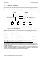
Basic VRRP Configuration . . . . . . . . . . . . . . . . . . . . . . . . . . . . . . . . . . . . . . . . . . . . . . . . . . . . . 12-2
Symmetrical Configuration . . . . . . . . . . . . . . . . . . . . . . . . . . . . . . . . . . . . . . . . . . . . . . . . . . . . . 12-3
Multi-Backup Configuration . . . . . . . . . . . . . . . . . . . . . . . . . . . . . . . . . . . . . . . . . . . . . . . . . . . . 12-5
Riverstone Networks RS Switch Router User Guide Release 8.0 xvii
12.2
12.2.1
12.2.2
12.2.3
12.2.4
12.2.5
Additional Configuration. . . . . . . . . . . . . . . . . . . . . . . . . . . . . . . . . . . . . . . . . . . . . . . . . . . . . . . . . . . 12-9
Setting the Backup Priority . . . . . . . . . . . . . . . . . . . . . . . . . . . . . . . . . . . . . . . . . . . . . . . . . . . . . 12-9
Setting the Warmup Period . . . . . . . . . . . . . . . . . . . . . . . . . . . . . . . . . . . . . . . . . . . . . . . . . . . . . 12-9
Setting the Advertisement Interval. . . . . . . . . . . . . . . . . . . . . . . . . . . . . . . . . . . . . . . . . . . . . . . . 12-9
Setting Pre-empt Mode. . . . . . . . . . . . . . . . . . . . . . . . . . . . . . . . . . . . . . . . . . . . . . . . . . . . . . . . 12-10
Setting an Authentication Key . . . . . . . . . . . . . . . . . . . . . . . . . . . . . . . . . . . . . . . . . . . . . . . . . . 12-10
12.3
12.3.1
12.3.2
Monitoring VRRP . . . . . . . . . . . . . . . . . . . . . . . . . . . . . . . . . . . . . . . . . . . . . . . . . . . . . . . . . . . . . . . 12-10
ip-redundancy trace . . . . . . . . . . . . . . . . . . . . . . . . . . . . . . . . . . . . . . . . . . . . . . . . . . . . . . . . . . 12-11
ip-redundancy show . . . . . . . . . . . . . . . . . . . . . . . . . . . . . . . . . . . . . . . . . . . . . . . . . . . . . . . . . . 12-11
12.4
VRRP Configuration Notes . . . . . . . . . . . . . . . . . . . . . . . . . . . . . . . . . . . . . . . . . . . . . . . . . . . . . . . . 12-13
13
RIP Configuration Guide . . . . . . . . . . . . . . . . . . . . . . . . . . . . . . . . . . . . . . . 13-1
13.1
13.1.1
13.1.2
Configuring RIP . . . . . . . . . . . . . . . . . . . . . . . . . . . . . . . . . . . . . . . . . . . . . . . . . . . . . . . . . . . . . . . . . 13-1
Enabling and Disabling RIP . . . . . . . . . . . . . . . . . . . . . . . . . . . . . . . . . . . . . . . . . . . . . . . . . . . . . 13-1
Configuring RIP Interfaces. . . . . . . . . . . . . . . . . . . . . . . . . . . . . . . . . . . . . . . . . . . . . . . . . . . . . . 13-1
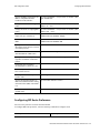
13.2
13.2.1
Configuring RIP Parameters . . . . . . . . . . . . . . . . . . . . . . . . . . . . . . . . . . . . . . . . . . . . . . . . . . . . . . . . 13-2
Configuring RIP Route Default-Metric . . . . . . . . . . . . . . . . . . . . . . . . . . . . . . . . . . . . . . . . . . . . 13-4
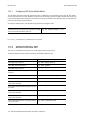
13.3
Monitoring RIP . . . . . . . . . . . . . . . . . . . . . . . . . . . . . . . . . . . . . . . . . . . . . . . . . . . . . . . . . . . . . . . . . . 13-4
13.4
Configuration Example . . . . . . . . . . . . . . . . . . . . . . . . . . . . . . . . . . . . . . . . . . . . . . . . . . . . . . . . . . . . 13-5
14
OSPF Configuration Guide . . . . . . . . . . . . . . . . . . . . . . . . . . . . . . . . . . . . .14-1
14.1
OSPF Multipath . . . . . . . . . . . . . . . . . . . . . . . . . . . . . . . . . . . . . . . . . . . . . . . . . . . . . . . . . . . . . . . . . . 14-2
14.2
Configuring OSPF . . . . . . . . . . . . . . . . . . . . . . . . . . . . . . . . . . . . . . . . . . . . . . . . . . . . . . . . . . . . . . . . 14-2
14.3
Setting the Router ID . . . . . . . . . . . . . . . . . . . . . . . . . . . . . . . . . . . . . . . . . . . . . . . . . . . . . . . . . . . . . . 14-2
14.4
Enabling OSPF . . . . . . . . . . . . . . . . . . . . . . . . . . . . . . . . . . . . . . . . . . . . . . . . . . . . . . . . . . . . . . . . . . 14-3
14.5
14.5.1
14.5.2
14.5.3
Configuring OSPF Areas. . . . . . . . . . . . . . . . . . . . . . . . . . . . . . . . . . . . . . . . . . . . . . . . . . . . . . . . . . . 14-3
Configuring Summary Ranges . . . . . . . . . . . . . . . . . . . . . . . . . . . . . . . . . . . . . . . . . . . . . . . . . . . 14-4
Configuring Stub Areas . . . . . . . . . . . . . . . . . . . . . . . . . . . . . . . . . . . . . . . . . . . . . . . . . . . . . . . . 14-4
Configuring Not-So-Stubby Areas (NSSA) . . . . . . . . . . . . . . . . . . . . . . . . . . . . . . . . . . . . . . . . . 14-5
14.6
14.6.1
14.6.2
14.6.3
Configuring OSPF Interfaces . . . . . . . . . . . . . . . . . . . . . . . . . . . . . . . . . . . . . . . . . . . . . . . . . . . . . . . 14-6
Configuring Interfaces for NBMA Networks. . . . . . . . . . . . . . . . . . . . . . . . . . . . . . . . . . . . . . . . 14-6
Configuring Interfaces for Point-to-Multipoint Networks . . . . . . . . . . . . . . . . . . . . . . . . . . . . . . 14-7
Configuring Interfaces for Point-to-Point Networks . . . . . . . . . . . . . . . . . . . . . . . . . . . . . . . . . . 14-7
14.7
14.7.1
14.7.2
Configuring OSPF Interface Parameters . . . . . . . . . . . . . . . . . . . . . . . . . . . . . . . . . . . . . . . . . . . . . . . 14-7
Setting the Interface State. . . . . . . . . . . . . . . . . . . . . . . . . . . . . . . . . . . . . . . . . . . . . . . . . . . . . . . 14-8
Setting the Default Cost of an OSPF Interface. . . . . . . . . . . . . . . . . . . . . . . . . . . . . . . . . . . . . . . 14-8
14.8
Creating Virtual Links . . . . . . . . . . . . . . . . . . . . . . . . . . . . . . . . . . . . . . . . . . . . . . . . . . . . . . . . . . . . . 14-8
14.9
14.9.1
Configuring OSPF Parameters . . . . . . . . . . . . . . . . . . . . . . . . . . . . . . . . . . . . . . . . . . . . . . . . . . . . . . 14-9
Configuring OSPF Global Parameters . . . . . . . . . . . . . . . . . . . . . . . . . . . . . . . . . . . . . . . . . . . . 14-10
14.10
Monitoring OSPF . . . . . . . . . . . . . . . . . . . . . . . . . . . . . . . . . . . . . . . . . . . . . . . . . . . . . . . . . . . . . . . 14-12
14.11
14.11.1
14.11.2
OSPF Configuration Examples . . . . . . . . . . . . . . . . . . . . . . . . . . . . . . . . . . . . . . . . . . . . . . . . . . . . . 14-14
Exporting All Interface & Static Routes to OSPF . . . . . . . . . . . . . . . . . . . . . . . . . . . . . . . . . . . 14-15
Exporting All RIP, Interface & Static Routes to OSPF . . . . . . . . . . . . . . . . . . . . . . . . . . . . . . . 14-15
xviii Riverstone Networks RS Switch Router User Guide Release 8.0
15
IS-IS Configuration Guide . . . . . . . . . . . . . . . . . . . . . . . . . . . . . . . . . . . . . 15-1
15.1
Defining an IS-IS Area . . . . . . . . . . . . . . . . . . . . . . . . . . . . . . . . . . . . . . . . . . . . . . . . . . . . . . . . . . . . 15-1
15.2
Configuring IS-IS Interfaces . . . . . . . . . . . . . . . . . . . . . . . . . . . . . . . . . . . . . . . . . . . . . . . . . . . . . . . . 15-1
15.3
Enabling IS-IS on the RS . . . . . . . . . . . . . . . . . . . . . . . . . . . . . . . . . . . . . . . . . . . . . . . . . . . . . . . . . . 15-2
15.4
15.4.1
15.4.2
15.4.3
15.4.4
15.4.5
15.4.6
Setting IS-IS Global Parameters . . . . . . . . . . . . . . . . . . . . . . . . . . . . . . . . . . . . . . . . . . . . . . . . . . . . . 15-2
Setting the IS Operating Level. . . . . . . . . . . . . . . . . . . . . . . . . . . . . . . . . . . . . . . . . . . . . . . . . . . 15-2
Setting the PSN Interval. . . . . . . . . . . . . . . . . . . . . . . . . . . . . . . . . . . . . . . . . . . . . . . . . . . . . . . . 15-2
Setting the System ID . . . . . . . . . . . . . . . . . . . . . . . . . . . . . . . . . . . . . . . . . . . . . . . . . . . . . . . . . 15-3
Setting the SPF Interval . . . . . . . . . . . . . . . . . . . . . . . . . . . . . . . . . . . . . . . . . . . . . . . . . . . . . . . . 15-3
Setting the Overload Bit. . . . . . . . . . . . . . . . . . . . . . . . . . . . . . . . . . . . . . . . . . . . . . . . . . . . . . . . 15-3
Setting IS-IS Authentication . . . . . . . . . . . . . . . . . . . . . . . . . . . . . . . . . . . . . . . . . . . . . . . . . . . . 15-4
15.5
15.5.1
15.5.2
15.5.3
15.5.4
Setting IS-IS Interface Parameters . . . . . . . . . . . . . . . . . . . . . . . . . . . . . . . . . . . . . . . . . . . . . . . . . . . 15-5
Setting the Interface Operating Level . . . . . . . . . . . . . . . . . . . . . . . . . . . . . . . . . . . . . . . . . . . . . 15-5
Setting Interface Parameters for a Designated Intermediate System (DIS). . . . . . . . . . . . . . . . . 15-6
Setting IS-IS Interface Timers . . . . . . . . . . . . . . . . . . . . . . . . . . . . . . . . . . . . . . . . . . . . . . . . . . . 15-6
Setting Mesh Group Membership . . . . . . . . . . . . . . . . . . . . . . . . . . . . . . . . . . . . . . . . . . . . . . . . 15-6
15.6
15.6.1
Displaying IS-IS Information . . . . . . . . . . . . . . . . . . . . . . . . . . . . . . . . . . . . . . . . . . . . . . . . . . . . . . . 15-7
IS-IS Sample Configuration. . . . . . . . . . . . . . . . . . . . . . . . . . . . . . . . . . . . . . . . . . . . . . . . . . . . . 15-7
16
BGP Configuration Guide. . . . . . . . . . . . . . . . . . . . . . . . . . . . . . . . . . . . . . 16-1
16.1
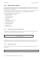
The RS BGP Implementation . . . . . . . . . . . . . . . . . . . . . . . . . . . . . . . . . . . . . . . . . . . . . . . . . . . . . . . 16-1
16.2
16.2.1
16.2.2
16.2.3
16.2.4
16.2.5
16.2.6
16.2.7
16.2.8
16.2.9
16.2.10
16.2.11
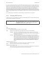
Basic BGP Tasks . . . . . . . . . . . . . . . . . . . . . . . . . . . . . . . . . . . . . . . . . . . . . . . . . . . . . . . . . . . . . . . . . 16-2
Setting the Autonomous System Number . . . . . . . . . . . . . . . . . . . . . . . . . . . . . . . . . . . . . . . . . . 16-2
Setting the Router ID . . . . . . . . . . . . . . . . . . . . . . . . . . . . . . . . . . . . . . . . . . . . . . . . . . . . . . . . . . 16-2
Configuring a BGP Peer Group . . . . . . . . . . . . . . . . . . . . . . . . . . . . . . . . . . . . . . . . . . . . . . . . . . 16-3
Adding a BGP Peer . . . . . . . . . . . . . . . . . . . . . . . . . . . . . . . . . . . . . . . . . . . . . . . . . . . . . . . . . . . 16-4
Starting BGP . . . . . . . . . . . . . . . . . . . . . . . . . . . . . . . . . . . . . . . . . . . . . . . . . . . . . . . . . . . . . . . . 16-4
Using AS-Path Regular Expressions . . . . . . . . . . . . . . . . . . . . . . . . . . . . . . . . . . . . . . . . . . . . . . 16-4
Using the AS Path Prepend Feature. . . . . . . . . . . . . . . . . . . . . . . . . . . . . . . . . . . . . . . . . . . . . . . 16-6
Creating BGP Confederations . . . . . . . . . . . . . . . . . . . . . . . . . . . . . . . . . . . . . . . . . . . . . . . . . . . 16-7
Creating Community Lists . . . . . . . . . . . . . . . . . . . . . . . . . . . . . . . . . . . . . . . . . . . . . . . . . . . . . . 16-8
Using Route Maps . . . . . . . . . . . . . . . . . . . . . . . . . . . . . . . . . . . . . . . . . . . . . . . . . . . . . . . . . . . . 16-9
Using BGP Accounting . . . . . . . . . . . . . . . . . . . . . . . . . . . . . . . . . . . . . . . . . . . . . . . . . . . . . . . 16-11
16.3
16.3.1
16.3.2
16.3.3
16.3.4
16.3.5
16.3.6
16.3.7
16.3.8
16.3.9
16.3.10
16.3.11
BGP Configuration Examples. . . . . . . . . . . . . . . . . . . . . . . . . . . . . . . . . . . . . . . . . . . . . . . . . . . . . . 16-13
BGP Peering Session Example . . . . . . . . . . . . . . . . . . . . . . . . . . . . . . . . . . . . . . . . . . . . . . . . . 16-14
IBGP Configuration Example . . . . . . . . . . . . . . . . . . . . . . . . . . . . . . . . . . . . . . . . . . . . . . . . . . 16-16
EBGP Multihop Configuration Example. . . . . . . . . . . . . . . . . . . . . . . . . . . . . . . . . . . . . . . . . . 16-19
Community Attribute Example . . . . . . . . . . . . . . . . . . . . . . . . . . . . . . . . . . . . . . . . . . . . . . . . . 16-22
Local Preference Examples . . . . . . . . . . . . . . . . . . . . . . . . . . . . . . . . . . . . . . . . . . . . . . . . . . . . 16-29
Multi-Exit Discriminator Attribute Example. . . . . . . . . . . . . . . . . . . . . . . . . . . . . . . . . . . . . . . 16-32
EBGP Aggregation Example . . . . . . . . . . . . . . . . . . . . . . . . . . . . . . . . . . . . . . . . . . . . . . . . . . . 16-33
Route Reflection Example . . . . . . . . . . . . . . . . . . . . . . . . . . . . . . . . . . . . . . . . . . . . . . . . . . . . . 16-34
BGP Confederation Example. . . . . . . . . . . . . . . . . . . . . . . . . . . . . . . . . . . . . . . . . . . . . . . . . . . 16-37
Route Map Example. . . . . . . . . . . . . . . . . . . . . . . . . . . . . . . . . . . . . . . . . . . . . . . . . . . . . . . . . . 16-42
BGP Accounting Examples . . . . . . . . . . . . . . . . . . . . . . . . . . . . . . . . . . . . . . . . . . . . . . . . . . . . 16-43
17
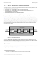
MPLS Configuration . . . . . . . . . . . . . . . . . . . . . . . . . . . . . . . . . . . . . . . . . . 17-1
17.1
17.1.1
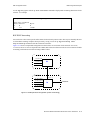
MPLS Architecture Overview. . . . . . . . . . . . . . . . . . . . . . . . . . . . . . . . . . . . . . . . . . . . . . . . . . . . . . . 17-2
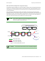
Labels . . . . . . . . . . . . . . . . . . . . . . . . . . . . . . . . . . . . . . . . . . . . . . . . . . . . . . . . . . . . . . . . . . . . . . 17-2
Riverstone Networks RS Switch Router User Guide Release 8.0 xix
17.1.2
17.1.3
17.1.4
17.1.5
17.1.6
Label Binding . . . . . . . . . . . . . . . . . . . . . . . . . . . . . . . . . . . . . . . . . . . . . . . . . . . . . . . . . . . . . . . . 17-5
Label Distribution and Management . . . . . . . . . . . . . . . . . . . . . . . . . . . . . . . . . . . . . . . . . . . . . . 17-5
Penultimate Hop Popping. . . . . . . . . . . . . . . . . . . . . . . . . . . . . . . . . . . . . . . . . . . . . . . . . . . . . . . 17-7
MPLS Tunnels . . . . . . . . . . . . . . . . . . . . . . . . . . . . . . . . . . . . . . . . . . . . . . . . . . . . . . . . . . . . . . . 17-7
MPLS Table Information . . . . . . . . . . . . . . . . . . . . . . . . . . . . . . . . . . . . . . . . . . . . . . . . . . . . . . . 17-8
17.2
Enabling and Starting MPLS on the RS . . . . . . . . . . . . . . . . . . . . . . . . . . . . . . . . . . . . . . . . . . . . . . 17-11
17.3
17.3.1
17.3.2
17.3.3
17.3.4
17.3.5
17.3.6
17.3.7
RSVP Configuration . . . . . . . . . . . . . . . . . . . . . . . . . . . . . . . . . . . . . . . . . . . . . . . . . . . . . . . . . . . . . 17-13
Establishing RSVP Sessions. . . . . . . . . . . . . . . . . . . . . . . . . . . . . . . . . . . . . . . . . . . . . . . . . . . . 17-14
RSVP Refresh Intervals . . . . . . . . . . . . . . . . . . . . . . . . . . . . . . . . . . . . . . . . . . . . . . . . . . . . . . . 17-15
RSVP Hello Packets . . . . . . . . . . . . . . . . . . . . . . . . . . . . . . . . . . . . . . . . . . . . . . . . . . . . . . . . . . 17-16
Authentication . . . . . . . . . . . . . . . . . . . . . . . . . . . . . . . . . . . . . . . . . . . . . . . . . . . . . . . . . . . . . . 17-17
Blockade Aging Interval. . . . . . . . . . . . . . . . . . . . . . . . . . . . . . . . . . . . . . . . . . . . . . . . . . . . . . . 17-18
RSVP Refresh Reduction . . . . . . . . . . . . . . . . . . . . . . . . . . . . . . . . . . . . . . . . . . . . . . . . . . . . . . 17-18
Displaying RSVP Information . . . . . . . . . . . . . . . . . . . . . . . . . . . . . . . . . . . . . . . . . . . . . . . . . . 17-20
17.4
17.4.1
17.4.2
17.4.3
17.4.4
17.4.5
17.4.6
17.4.7
LDP Configuration . . . . . . . . . . . . . . . . . . . . . . . . . . . . . . . . . . . . . . . . . . . . . . . . . . . . . . . . . . . . . . 17-21
Establishing LDP Sessions . . . . . . . . . . . . . . . . . . . . . . . . . . . . . . . . . . . . . . . . . . . . . . . . . . . . . 17-21
Monitoring LDP Sessions. . . . . . . . . . . . . . . . . . . . . . . . . . . . . . . . . . . . . . . . . . . . . . . . . . . . . . 17-22
Remote Peers . . . . . . . . . . . . . . . . . . . . . . . . . . . . . . . . . . . . . . . . . . . . . . . . . . . . . . . . . . . . . . . 17-23
Loop Detection . . . . . . . . . . . . . . . . . . . . . . . . . . . . . . . . . . . . . . . . . . . . . . . . . . . . . . . . . . . . . . 17-23
MD5 Password Protection . . . . . . . . . . . . . . . . . . . . . . . . . . . . . . . . . . . . . . . . . . . . . . . . . . . . . 17-24
Using LDP Filters. . . . . . . . . . . . . . . . . . . . . . . . . . . . . . . . . . . . . . . . . . . . . . . . . . . . . . . . . . . . 17-24
Displaying LDP Information . . . . . . . . . . . . . . . . . . . . . . . . . . . . . . . . . . . . . . . . . . . . . . . . . . . 17-26
17.5
17.5.1
17.5.2
17.5.3
Configuring L3 Label Switched Paths. . . . . . . . . . . . . . . . . . . . . . . . . . . . . . . . . . . . . . . . . . . . . . . . 17-27
Configuring L3 Static LSPs . . . . . . . . . . . . . . . . . . . . . . . . . . . . . . . . . . . . . . . . . . . . . . . . . . . . 17-27
Configuring L3 Dynamic LSPs . . . . . . . . . . . . . . . . . . . . . . . . . . . . . . . . . . . . . . . . . . . . . . . . . 17-31
Configuring an Explicit LSP . . . . . . . . . . . . . . . . . . . . . . . . . . . . . . . . . . . . . . . . . . . . . . . . . . . 17-32
17.6
17.6.1
17.6.2
Configuring L2 Tunnels . . . . . . . . . . . . . . . . . . . . . . . . . . . . . . . . . . . . . . . . . . . . . . . . . . . . . . . . . . 17-60
Configuring L2 Static Labels . . . . . . . . . . . . . . . . . . . . . . . . . . . . . . . . . . . . . . . . . . . . . . . . . . . 17-60
Configuring Dynamic L2 Labels . . . . . . . . . . . . . . . . . . . . . . . . . . . . . . . . . . . . . . . . . . . . . . . . 17-65
17.7
17.7.1
17.7.2
17.7.3
Traffic Engineering . . . . . . . . . . . . . . . . . . . . . . . . . . . . . . . . . . . . . . . . . . . . . . . . . . . . . . . . . . . . . 17-102
Administrative Groups . . . . . . . . . . . . . . . . . . . . . . . . . . . . . . . . . . . . . . . . . . . . . . . . . . . . . . . 17-102
Constrained Shortest Path First . . . . . . . . . . . . . . . . . . . . . . . . . . . . . . . . . . . . . . . . . . . . . . . . 17-104
IGP Shortcuts . . . . . . . . . . . . . . . . . . . . . . . . . . . . . . . . . . . . . . . . . . . . . . . . . . . . . . . . . . . . . . 17-119
18
Routing Policy Configuration. . . . . . . . . . . . . . . . . . . . . . . . . . . . . . . . . . . . 18-1
18.1
18.1.1
18.1.2
18.1.3
18.1.4
18.1.5
Preference . . . . . . . . . . . . . . . . . . . . . . . . . . . . . . . . . . . . . . . . . . . . . . . . . . . . . . . . . . . . . . . . . . . . . . 18-1
Import Policies . . . . . . . . . . . . . . . . . . . . . . . . . . . . . . . . . . . . . . . . . . . . . . . . . . . . . . . . . . . . . . . 18-2
Export Policies . . . . . . . . . . . . . . . . . . . . . . . . . . . . . . . . . . . . . . . . . . . . . . . . . . . . . . . . . . . . . . . 18-3
Specifying a Route Filter . . . . . . . . . . . . . . . . . . . . . . . . . . . . . . . . . . . . . . . . . . . . . . . . . . . . . . . 18-4
Aggregates and Generates . . . . . . . . . . . . . . . . . . . . . . . . . . . . . . . . . . . . . . . . . . . . . . . . . . . . . . 18-5
Authentication . . . . . . . . . . . . . . . . . . . . . . . . . . . . . . . . . . . . . . . . . . . . . . . . . . . . . . . . . . . . . . . 18-6
18.2
18.2.1
18.2.2
18.2.3
18.2.4
18.2.5
18.2.6
18.2.7
Configuring Simple Routing Policies . . . . . . . . . . . . . . . . . . . . . . . . . . . . . . . . . . . . . . . . . . . . . . . . . 18-7
Redistributing Static Routes . . . . . . . . . . . . . . . . . . . . . . . . . . . . . . . . . . . . . . . . . . . . . . . . . . . . . 18-8
Redistributing Directly Attached Networks . . . . . . . . . . . . . . . . . . . . . . . . . . . . . . . . . . . . . . . . . 18-8
Redistributing RIP into RIP . . . . . . . . . . . . . . . . . . . . . . . . . . . . . . . . . . . . . . . . . . . . . . . . . . . . . 18-9
Redistributing RIP into OSPF . . . . . . . . . . . . . . . . . . . . . . . . . . . . . . . . . . . . . . . . . . . . . . . . . . . 18-9
Redistributing OSPF to RIP . . . . . . . . . . . . . . . . . . . . . . . . . . . . . . . . . . . . . . . . . . . . . . . . . . . . . 18-9
Redistributing Aggregate Routes . . . . . . . . . . . . . . . . . . . . . . . . . . . . . . . . . . . . . . . . . . . . . . . . 18-10
Simple Route Redistribution Example: Redistribution into RIP . . . . . . . . . . . . . . . . . . . . . . . . 18-10
xx
Riverstone Networks RS Switch Router User Guide Release 8.0
18.2.8
Simple Route Redistribution Example: Redistribution into OSPF . . . . . . . . . . . . . . . . . . . . . . 18-12
18.3
18.3.1
18.3.2
18.3.3
18.3.4
18.3.5
18.3.6
18.3.7
18.3.8
18.3.9
18.3.10
18.3.11
18.3.12
18.3.13
Configuring Advanced Routing Policies. . . . . . . . . . . . . . . . . . . . . . . . . . . . . . . . . . . . . . . . . . . . . . 18-13
Export Policies . . . . . . . . . . . . . . . . . . . . . . . . . . . . . . . . . . . . . . . . . . . . . . . . . . . . . . . . . . . . . . 18-14
Creating an Export Destination . . . . . . . . . . . . . . . . . . . . . . . . . . . . . . . . . . . . . . . . . . . . . . . . . 18-15
Creating an Export Source . . . . . . . . . . . . . . . . . . . . . . . . . . . . . . . . . . . . . . . . . . . . . . . . . . . . . 18-15
Import Policies . . . . . . . . . . . . . . . . . . . . . . . . . . . . . . . . . . . . . . . . . . . . . . . . . . . . . . . . . . . . . . 18-15
Creating an Import Source . . . . . . . . . . . . . . . . . . . . . . . . . . . . . . . . . . . . . . . . . . . . . . . . . . . . . 18-16
Creating a Route Filter . . . . . . . . . . . . . . . . . . . . . . . . . . . . . . . . . . . . . . . . . . . . . . . . . . . . . . . . 18-16
Creating an Aggregate Route. . . . . . . . . . . . . . . . . . . . . . . . . . . . . . . . . . . . . . . . . . . . . . . . . . . 18-16
Creating an Aggregate Destination . . . . . . . . . . . . . . . . . . . . . . . . . . . . . . . . . . . . . . . . . . . . . . 18-17
Creating an Aggregate Source . . . . . . . . . . . . . . . . . . . . . . . . . . . . . . . . . . . . . . . . . . . . . . . . . . 18-18
Import Policies Example: Importing from RIP . . . . . . . . . . . . . . . . . . . . . . . . . . . . . . . . . . . . . 18-18
Import Policies Example: Importing from OSPF . . . . . . . . . . . . . . . . . . . . . . . . . . . . . . . . . . . 18-21
Export Policies Example: Exporting to RIP . . . . . . . . . . . . . . . . . . . . . . . . . . . . . . . . . . . . . . . 18-24
Export Policies Example: Exporting to OSPF . . . . . . . . . . . . . . . . . . . . . . . . . . . . . . . . . . . . . . 18-29
19
Multicast Routing Configuration . . . . . . . . . . . . . . . . . . . . . . . . . . . . . . . . . 19-1
19.1
IGMP Overview . . . . . . . . . . . . . . . . . . . . . . . . . . . . . . . . . . . . . . . . . . . . . . . . . . . . . . . . . . . . . . . . . 19-1
19.2
DVMRP Overview . . . . . . . . . . . . . . . . . . . . . . . . . . . . . . . . . . . . . . . . . . . . . . . . . . . . . . . . . . . . . . . 19-1
19.3
19.3.1
19.3.2
19.3.3
19.3.4
19.3.5
Configuring IGMP . . . . . . . . . . . . . . . . . . . . . . . . . . . . . . . . . . . . . . . . . . . . . . . . . . . . . . . . . . . . . . . 19-2
Configuring IGMP on an IP Interface . . . . . . . . . . . . . . . . . . . . . . . . . . . . . . . . . . . . . . . . . . . . . 19-2
Configuring IGMP Query Interval. . . . . . . . . . . . . . . . . . . . . . . . . . . . . . . . . . . . . . . . . . . . . . . . 19-3
Configuring IGMP Response Wait Time. . . . . . . . . . . . . . . . . . . . . . . . . . . . . . . . . . . . . . . . . . . 19-3
Configuring Per-Interface Control of IGMP Membership . . . . . . . . . . . . . . . . . . . . . . . . . . . . . 19-3
Configuring Static IGMP Groups . . . . . . . . . . . . . . . . . . . . . . . . . . . . . . . . . . . . . . . . . . . . . . . . 19-3
19.4
19.4.1
19.4.2
19.4.3
19.4.4
19.4.5
19.4.6
Configuring DVMRP . . . . . . . . . . . . . . . . . . . . . . . . . . . . . . . . . . . . . . . . . . . . . . . . . . . . . . . . . . . . . 19-4
Starting and Stopping DVMRP . . . . . . . . . . . . . . . . . . . . . . . . . . . . . . . . . . . . . . . . . . . . . . . . . . 19-4
Configuring DVMRP on an Interface . . . . . . . . . . . . . . . . . . . . . . . . . . . . . . . . . . . . . . . . . . . . . 19-4
Configuring DVMRP Parameters . . . . . . . . . . . . . . . . . . . . . . . . . . . . . . . . . . . . . . . . . . . . . . . . 19-4
Configuring the DVMRP Routing Metric . . . . . . . . . . . . . . . . . . . . . . . . . . . . . . . . . . . . . . . . . . 19-5
Configuring DVMRP TTL & Scope . . . . . . . . . . . . . . . . . . . . . . . . . . . . . . . . . . . . . . . . . . . . . . 19-5
Configuring a DVMRP Tunnel . . . . . . . . . . . . . . . . . . . . . . . . . . . . . . . . . . . . . . . . . . . . . . . . . . 19-6
19.5
Monitoring IGMP & DVMRP . . . . . . . . . . . . . . . . . . . . . . . . . . . . . . . . . . . . . . . . . . . . . . . . . . . . . . 19-6
19.6
Configuration Example . . . . . . . . . . . . . . . . . . . . . . . . . . . . . . . . . . . . . . . . . . . . . . . . . . . . . . . . . . . . 19-7
20
IP Policy-Based Forwarding Configuration. . . . . . . . . . . . . . . . . . . . . . . . . 20-1
20.1
20.1.1
20.1.2
20.1.3
Configuring IP Policies . . . . . . . . . . . . . . . . . . . . . . . . . . . . . . . . . . . . . . . . . . . . . . . . . . . . . . . . . . . . 20-1
Defining an ACL Profile . . . . . . . . . . . . . . . . . . . . . . . . . . . . . . . . . . . . . . . . . . . . . . . . . . . . . . . 20-2
Associating the Profile with an IP Policy . . . . . . . . . . . . . . . . . . . . . . . . . . . . . . . . . . . . . . . . . . 20-2
Applying an IP Policy to an Interface . . . . . . . . . . . . . . . . . . . . . . . . . . . . . . . . . . . . . . . . . . . . . 20-5
20.2
20.2.1
20.2.2
20.2.3
20.2.4
IP Policy Configuration Examples . . . . . . . . . . . . . . . . . . . . . . . . . . . . . . . . . . . . . . . . . . . . . . . . . . . 20-5
Routing Traffic to Different ISPs. . . . . . . . . . . . . . . . . . . . . . . . . . . . . . . . . . . . . . . . . . . . . . . . . 20-6
Prioritizing Service to Customers . . . . . . . . . . . . . . . . . . . . . . . . . . . . . . . . . . . . . . . . . . . . . . . . 20-7
Authenticating Users through a Firewall . . . . . . . . . . . . . . . . . . . . . . . . . . . . . . . . . . . . . . . . . . . 20-8
Firewall Load Balancing . . . . . . . . . . . . . . . . . . . . . . . . . . . . . . . . . . . . . . . . . . . . . . . . . . . . . . . 20-9
20.3
Monitoring IP Policies . . . . . . . . . . . . . . . . . . . . . . . . . . . . . . . . . . . . . . . . . . . . . . . . . . . . . . . . . . . 20-11
Riverstone Networks RS Switch Router User Guide Release 8.0 xxi
21
Network Address Translation Configuration . . . . . . . . . . . . . . . . . . . . . . . . 21-1
21.1
21.1.1
21.1.2
Configuring NAT. . . . . . . . . . . . . . . . . . . . . . . . . . . . . . . . . . . . . . . . . . . . . . . . . . . . . . . . . . . . . . . . . 21-1
Setting Inside and Outside Interfaces . . . . . . . . . . . . . . . . . . . . . . . . . . . . . . . . . . . . . . . . . . . . . . 21-2
Setting NAT Rules . . . . . . . . . . . . . . . . . . . . . . . . . . . . . . . . . . . . . . . . . . . . . . . . . . . . . . . . . . . . 21-2
21.2
Forcing Flows through NAT . . . . . . . . . . . . . . . . . . . . . . . . . . . . . . . . . . . . . . . . . . . . . . . . . . . . . . . . 21-2
21.3
Managing Dynamic Bindings . . . . . . . . . . . . . . . . . . . . . . . . . . . . . . . . . . . . . . . . . . . . . . . . . . . . . . . 21-3
21.4
NAT and DNS . . . . . . . . . . . . . . . . . . . . . . . . . . . . . . . . . . . . . . . . . . . . . . . . . . . . . . . . . . . . . . . . . . . 21-3
21.5
NAT and ICMP Packets . . . . . . . . . . . . . . . . . . . . . . . . . . . . . . . . . . . . . . . . . . . . . . . . . . . . . . . . . . . 21-4
21.6
NAT and FTP . . . . . . . . . . . . . . . . . . . . . . . . . . . . . . . . . . . . . . . . . . . . . . . . . . . . . . . . . . . . . . . . . . . 21-4
21.7
Monitoring NAT . . . . . . . . . . . . . . . . . . . . . . . . . . . . . . . . . . . . . . . . . . . . . . . . . . . . . . . . . . . . . . . . . 21-5
21.8
21.8.1
21.8.2
21.8.3
21.8.4
21.8.5
Configuration Examples . . . . . . . . . . . . . . . . . . . . . . . . . . . . . . . . . . . . . . . . . . . . . . . . . . . . . . . . . . . 21-5
Static Configuration . . . . . . . . . . . . . . . . . . . . . . . . . . . . . . . . . . . . . . . . . . . . . . . . . . . . . . . . . . . 21-5
Dynamic Configuration . . . . . . . . . . . . . . . . . . . . . . . . . . . . . . . . . . . . . . . . . . . . . . . . . . . . . . . . 21-7
Dynamic NAT with IP Overload (PAT) Configuration . . . . . . . . . . . . . . . . . . . . . . . . . . . . . . . . 21-8
Dynamic NAT with DNS . . . . . . . . . . . . . . . . . . . . . . . . . . . . . . . . . . . . . . . . . . . . . . . . . . . . . . . 21-9
Dynamic NAT with Outside Interface Redundancy . . . . . . . . . . . . . . . . . . . . . . . . . . . . . . . . . 21-11
22
Web Hosting Configuration . . . . . . . . . . . . . . . . . . . . . . . . . . . . . . . . . . . . .22-1
22.1
22.1.1
22.1.2
22.1.3
22.1.4
22.1.5
22.1.6
22.1.7
22.1.8
22.1.9
22.1.10
22.1.11
22.1.12
Load Balancing . . . . . . . . . . . . . . . . . . . . . . . . . . . . . . . . . . . . . . . . . . . . . . . . . . . . . . . . . . . . . . . . . . 22-1
Creating the Server Group . . . . . . . . . . . . . . . . . . . . . . . . . . . . . . . . . . . . . . . . . . . . . . . . . . . . . . 22-2
Adding Servers to the Load Balancing Group . . . . . . . . . . . . . . . . . . . . . . . . . . . . . . . . . . . . . . . 22-3
Setting Timeouts for Load Balancing Mappings . . . . . . . . . . . . . . . . . . . . . . . . . . . . . . . . . . . . . 22-4
Optional Group or Server Operating Parameters . . . . . . . . . . . . . . . . . . . . . . . . . . . . . . . . . . . . . 22-5
Using Health Check Clusters . . . . . . . . . . . . . . . . . . . . . . . . . . . . . . . . . . . . . . . . . . . . . . . . . . . . 22-7
Setting Server Status. . . . . . . . . . . . . . . . . . . . . . . . . . . . . . . . . . . . . . . . . . . . . . . . . . . . . . . . . . . 22-7
Load Balancing and FTP . . . . . . . . . . . . . . . . . . . . . . . . . . . . . . . . . . . . . . . . . . . . . . . . . . . . . . . 22-8
Allowing Load Balancing Servers to Access the Internet . . . . . . . . . . . . . . . . . . . . . . . . . . . . . . 22-8
Allowing Access to Load Balancing Servers . . . . . . . . . . . . . . . . . . . . . . . . . . . . . . . . . . . . . . . . 22-8
Virtual State Replication Protocol (VSRP) . . . . . . . . . . . . . . . . . . . . . . . . . . . . . . . . . . . . . . . . . 22-8
Displaying Load Balancing Information . . . . . . . . . . . . . . . . . . . . . . . . . . . . . . . . . . . . . . . . . . 22-10
Configuration Examples. . . . . . . . . . . . . . . . . . . . . . . . . . . . . . . . . . . . . . . . . . . . . . . . . . . . . . . 22-10
22.2
22.2.1
22.2.2
22.2.3
22.2.4
Web Caching . . . . . . . . . . . . . . . . . . . . . . . . . . . . . . . . . . . . . . . . . . . . . . . . . . . . . . . . . . . . . . . . . . . 22-17
Configuring Web Caching . . . . . . . . . . . . . . . . . . . . . . . . . . . . . . . . . . . . . . . . . . . . . . . . . . . . . 22-17
Configuration Example . . . . . . . . . . . . . . . . . . . . . . . . . . . . . . . . . . . . . . . . . . . . . . . . . . . . . . . 22-19
Other Web-Cache Options . . . . . . . . . . . . . . . . . . . . . . . . . . . . . . . . . . . . . . . . . . . . . . . . . . . . . 22-19
Monitoring Web-Caching. . . . . . . . . . . . . . . . . . . . . . . . . . . . . . . . . . . . . . . . . . . . . . . . . . . . . . 22-22
23
IPX Routing Configuration. . . . . . . . . . . . . . . . . . . . . . . . . . . . . . . . . . . . . . 23-1
23.1
RIP (Routing Information Protocol) . . . . . . . . . . . . . . . . . . . . . . . . . . . . . . . . . . . . . . . . . . . . . . . . . . 23-1
23.2
SAP (Service Advertising Protocol) . . . . . . . . . . . . . . . . . . . . . . . . . . . . . . . . . . . . . . . . . . . . . . . . . . 23-2
23.3
23.3.1
23.3.2
23.3.3
23.3.4
Configuring IPX RIP & SAP. . . . . . . . . . . . . . . . . . . . . . . . . . . . . . . . . . . . . . . . . . . . . . . . . . . . . . . . 23-2
IPX RIP . . . . . . . . . . . . . . . . . . . . . . . . . . . . . . . . . . . . . . . . . . . . . . . . . . . . . . . . . . . . . . . . . . . . 23-2
IPX SAP . . . . . . . . . . . . . . . . . . . . . . . . . . . . . . . . . . . . . . . . . . . . . . . . . . . . . . . . . . . . . . . . . . . . 23-2
Creating IPX Interfaces . . . . . . . . . . . . . . . . . . . . . . . . . . . . . . . . . . . . . . . . . . . . . . . . . . . . . . . . 23-2
IPX Addresses . . . . . . . . . . . . . . . . . . . . . . . . . . . . . . . . . . . . . . . . . . . . . . . . . . . . . . . . . . . . . . . 23-3
23.4
Configuring IPX Interfaces and Parameters . . . . . . . . . . . . . . . . . . . . . . . . . . . . . . . . . . . . . . . . . . . . 23-3
xxii Riverstone Networks RS Switch Router User Guide Release 8.0
23.4.1
23.4.2
23.4.3
23.4.4
Configuring IPX Addresses to Ports . . . . . . . . . . . . . . . . . . . . . . . . . . . . . . . . . . . . . . . . . . . . . . 23-3
Configuring Secondary Addresses on an IPX Interface . . . . . . . . . . . . . . . . . . . . . . . . . . . . . . . 23-3
Configuring IPX Interfaces for a VLAN . . . . . . . . . . . . . . . . . . . . . . . . . . . . . . . . . . . . . . . . . . . 23-4
Specifying IPX Encapsulation Method . . . . . . . . . . . . . . . . . . . . . . . . . . . . . . . . . . . . . . . . . . . . 23-4
23.5
23.5.1
23.5.2
23.5.3
23.5.4
23.5.5
Configuring IPX Routing . . . . . . . . . . . . . . . . . . . . . . . . . . . . . . . . . . . . . . . . . . . . . . . . . . . . . . . . . . 23-5
Enabling IPX RIP. . . . . . . . . . . . . . . . . . . . . . . . . . . . . . . . . . . . . . . . . . . . . . . . . . . . . . . . . . . . . 23-5
Enabling SAP. . . . . . . . . . . . . . . . . . . . . . . . . . . . . . . . . . . . . . . . . . . . . . . . . . . . . . . . . . . . . . . . 23-5
Configuring Static Routes . . . . . . . . . . . . . . . . . . . . . . . . . . . . . . . . . . . . . . . . . . . . . . . . . . . . . . 23-5
Configuring Static SAP Table Entries . . . . . . . . . . . . . . . . . . . . . . . . . . . . . . . . . . . . . . . . . . . . . 23-5
Controlling Access to IPX Networks. . . . . . . . . . . . . . . . . . . . . . . . . . . . . . . . . . . . . . . . . . . . . . 23-6
23.6
Monitoring an IPX Network . . . . . . . . . . . . . . . . . . . . . . . . . . . . . . . . . . . . . . . . . . . . . . . . . . . . . . . . 23-8
23.7
Configuration Examples . . . . . . . . . . . . . . . . . . . . . . . . . . . . . . . . . . . . . . . . . . . . . . . . . . . . . . . . . . . 23-8
24
Access Control List Configuration . . . . . . . . . . . . . . . . . . . . . . . . . . . . . . . 24-1
24.1
24.1.1
24.1.2
24.1.3
24.1.4
ACL Basics . . . . . . . . . . . . . . . . . . . . . . . . . . . . . . . . . . . . . . . . . . . . . . . . . . . . . . . . . . . . . . . . . . . . . 24-1
Defining Selection Criteria in ACL Rules . . . . . . . . . . . . . . . . . . . . . . . . . . . . . . . . . . . . . . . . . . 24-1
How ACL Rules are Evaluated . . . . . . . . . . . . . . . . . . . . . . . . . . . . . . . . . . . . . . . . . . . . . . . . . . 24-3
Implicit Deny Rule. . . . . . . . . . . . . . . . . . . . . . . . . . . . . . . . . . . . . . . . . . . . . . . . . . . . . . . . . . . . 24-4
Allowing External Responses to Established TCP Connections . . . . . . . . . . . . . . . . . . . . . . . . . 24-5
24.2
24.2.1
24.2.2
Creating and Modifying ACLs . . . . . . . . . . . . . . . . . . . . . . . . . . . . . . . . . . . . . . . . . . . . . . . . . . . . . . 24-6
Editing ACLs Offline. . . . . . . . . . . . . . . . . . . . . . . . . . . . . . . . . . . . . . . . . . . . . . . . . . . . . . . . . . 24-6
Maintaining ACLs Using the ACL Editor . . . . . . . . . . . . . . . . . . . . . . . . . . . . . . . . . . . . . . . . . . 24-7
24.3
24.3.1
24.3.2
24.3.3
24.3.4
Using ACLs. . . . . . . . . . . . . . . . . . . . . . . . . . . . . . . . . . . . . . . . . . . . . . . . . . . . . . . . . . . . . . . . . . . . . 24-8
Applying ACLs to Interfaces . . . . . . . . . . . . . . . . . . . . . . . . . . . . . . . . . . . . . . . . . . . . . . . . . . . . 24-8
Applying ACLs to Services . . . . . . . . . . . . . . . . . . . . . . . . . . . . . . . . . . . . . . . . . . . . . . . . . . . . . 24-9
Applying ACLs to Layer-4 Bridging Ports . . . . . . . . . . . . . . . . . . . . . . . . . . . . . . . . . . . . . . . . . 24-9
Using ACLs as Profiles . . . . . . . . . . . . . . . . . . . . . . . . . . . . . . . . . . . . . . . . . . . . . . . . . . . . . . . 24-10
24.4
Enabling ACL Logging . . . . . . . . . . . . . . . . . . . . . . . . . . . . . . . . . . . . . . . . . . . . . . . . . . . . . . . . . . . 24-14
24.5
Monitoring ACLs . . . . . . . . . . . . . . . . . . . . . . . . . . . . . . . . . . . . . . . . . . . . . . . . . . . . . . . . . . . . . . . 24-15
25
Security Configuration . . . . . . . . . . . . . . . . . . . . . . . . . . . . . . . . . . . . . . . . 25-1
25.1
25.1.1
25.1.2
25.1.3
25.1.4
25.1.5
Configuring RS Access Security. . . . . . . . . . . . . . . . . . . . . . . . . . . . . . . . . . . . . . . . . . . . . . . . . . . . . 25-1
Configuring RADIUS . . . . . . . . . . . . . . . . . . . . . . . . . . . . . . . . . . . . . . . . . . . . . . . . . . . . . . . . . 25-1
Configuring TACACS . . . . . . . . . . . . . . . . . . . . . . . . . . . . . . . . . . . . . . . . . . . . . . . . . . . . . . . . . 25-3
Configuring TACACS+ . . . . . . . . . . . . . . . . . . . . . . . . . . . . . . . . . . . . . . . . . . . . . . . . . . . . . . . . 25-3
Configuring Passwords . . . . . . . . . . . . . . . . . . . . . . . . . . . . . . . . . . . . . . . . . . . . . . . . . . . . . . . . 25-5
Configuring SSH . . . . . . . . . . . . . . . . . . . . . . . . . . . . . . . . . . . . . . . . . . . . . . . . . . . . . . . . . . . . . 25-5
25.2
25.2.1
25.2.2
25.2.3
25.2.4
25.2.5
25.2.6
Layer-2 Security Filters. . . . . . . . . . . . . . . . . . . . . . . . . . . . . . . . . . . . . . . . . . . . . . . . . . . . . . . . . . . . 25-6
Configuring Layer-2 Address Filters . . . . . . . . . . . . . . . . . . . . . . . . . . . . . . . . . . . . . . . . . . . . . . 25-7
Configuring Layer-2 Port-to-Address Lock Filters . . . . . . . . . . . . . . . . . . . . . . . . . . . . . . . . . . . 25-7
Configuring Layer-2 Static Entry Filters . . . . . . . . . . . . . . . . . . . . . . . . . . . . . . . . . . . . . . . . . . . 25-8
Configuring Layer-2 Secure Port Filters . . . . . . . . . . . . . . . . . . . . . . . . . . . . . . . . . . . . . . . . . . . 25-8
Monitoring Layer-2 Security Filters . . . . . . . . . . . . . . . . . . . . . . . . . . . . . . . . . . . . . . . . . . . . . . 25-9
Layer-2 Filter Examples. . . . . . . . . . . . . . . . . . . . . . . . . . . . . . . . . . . . . . . . . . . . . . . . . . . . . . . . 25-9
25.3
Layer-3 Access Control Lists (ACLs). . . . . . . . . . . . . . . . . . . . . . . . . . . . . . . . . . . . . . . . . . . . . . . . 25-12
25.4
25.4.1
Layer-4 Bridging and Filtering . . . . . . . . . . . . . . . . . . . . . . . . . . . . . . . . . . . . . . . . . . . . . . . . . . . . . 25-12
Creating an IP or IPX VLAN for Layer-4 Bridging . . . . . . . . . . . . . . . . . . . . . . . . . . . . . . . . . 25-13
Riverstone Networks RS Switch Router User Guide Release 8.0 xxiii
25.4.2
25.4.3
25.4.4
25.4.5
25.4.6
Placing the Ports on the Same VLAN . . . . . . . . . . . . . . . . . . . . . . . . . . . . . . . . . . . . . . . . . . . . 25-14
Enabling Layer-4 Bridging on the VLAN . . . . . . . . . . . . . . . . . . . . . . . . . . . . . . . . . . . . . . . . . 25-14
Creating ACLs to Specify Selection Criteria for Layer-4 Bridging. . . . . . . . . . . . . . . . . . . . . . 25-14
Applying a Layer-4 Bridging ACL to a Port . . . . . . . . . . . . . . . . . . . . . . . . . . . . . . . . . . . . . . . 25-15
Notes. . . . . . . . . . . . . . . . . . . . . . . . . . . . . . . . . . . . . . . . . . . . . . . . . . . . . . . . . . . . . . . . . . . . . . 25-15
26
QoS Configuration. . . . . . . . . . . . . . . . . . . . . . . . . . . . . . . . . . . . . . . . . . . .26-1
26.1
Layer-2, Layer-3 and Layer-4 Flow Specification . . . . . . . . . . . . . . . . . . . . . . . . . . . . . . . . . . . . . . . 26-2
26.2
Precedence for Layer-3 Flows . . . . . . . . . . . . . . . . . . . . . . . . . . . . . . . . . . . . . . . . . . . . . . . . . . . . . . . 26-2
26.3
RS Queuing Policies . . . . . . . . . . . . . . . . . . . . . . . . . . . . . . . . . . . . . . . . . . . . . . . . . . . . . . . . . . . . . . 26-3
26.4
26.4.1
26.4.2
Traffic Prioritization for Layer-2 Flows . . . . . . . . . . . . . . . . . . . . . . . . . . . . . . . . . . . . . . . . . . . . . . . 26-3
Configuring Layer-2 QoS. . . . . . . . . . . . . . . . . . . . . . . . . . . . . . . . . . . . . . . . . . . . . . . . . . . . . . . 26-4
802.1p Class of Service Priority Mapping . . . . . . . . . . . . . . . . . . . . . . . . . . . . . . . . . . . . . . . . . . 26-4
26.5
26.5.1
26.5.2
Traffic Prioritization for Layer-3 & Layer-4 Flows . . . . . . . . . . . . . . . . . . . . . . . . . . . . . . . . . . . . . . 26-6
Configuring IP QoS Policies . . . . . . . . . . . . . . . . . . . . . . . . . . . . . . . . . . . . . . . . . . . . . . . . . . . . 26-6
Configuring IPX QoS Policies . . . . . . . . . . . . . . . . . . . . . . . . . . . . . . . . . . . . . . . . . . . . . . . . . . . 26-7
26.6
26.6.1
Configuring RS Queueing Policy . . . . . . . . . . . . . . . . . . . . . . . . . . . . . . . . . . . . . . . . . . . . . . . . . . . . 26-7
Allocating Bandwidth for a Weighted-Fair Queuing Policy . . . . . . . . . . . . . . . . . . . . . . . . . . . . 26-8
26.7
26.7.1
26.7.2
Weighted Random Early Detection (WRED) . . . . . . . . . . . . . . . . . . . . . . . . . . . . . . . . . . . . . . . . . . . 26-8
WRED’s Effect on the Network. . . . . . . . . . . . . . . . . . . . . . . . . . . . . . . . . . . . . . . . . . . . . . . . . . 26-8
Weighting Algorithms in WRED . . . . . . . . . . . . . . . . . . . . . . . . . . . . . . . . . . . . . . . . . . . . . . . . . 26-8
26.8
26.8.1
ToS Rewrite . . . . . . . . . . . . . . . . . . . . . . . . . . . . . . . . . . . . . . . . . . . . . . . . . . . . . . . . . . . . . . . . . . . . 26-10
Configuring ToS Rewrite for IP Packets . . . . . . . . . . . . . . . . . . . . . . . . . . . . . . . . . . . . . . . . . . 26-10
26.9
Monitoring QoS . . . . . . . . . . . . . . . . . . . . . . . . . . . . . . . . . . . . . . . . . . . . . . . . . . . . . . . . . . . . . . . . . 26-12
26.10
26.10.1
26.10.2
26.10.3
26.10.4
26.10.5
26.10.6
26.10.7
Limiting Traffic Rate. . . . . . . . . . . . . . . . . . . . . . . . . . . . . . . . . . . . . . . . . . . . . . . . . . . . . . . . . . . . . 26-13
Rate Limiting Modes . . . . . . . . . . . . . . . . . . . . . . . . . . . . . . . . . . . . . . . . . . . . . . . . . . . . . . . . . 26-14
Per-Flow Rate Limiting . . . . . . . . . . . . . . . . . . . . . . . . . . . . . . . . . . . . . . . . . . . . . . . . . . . . . . . 26-14
Software-Based Flow-Aggregate Rate Limiting . . . . . . . . . . . . . . . . . . . . . . . . . . . . . . . . . . . . 26-15
Port Rate Limiting . . . . . . . . . . . . . . . . . . . . . . . . . . . . . . . . . . . . . . . . . . . . . . . . . . . . . . . . . . . 26-15
Aggregate Rate Limiting . . . . . . . . . . . . . . . . . . . . . . . . . . . . . . . . . . . . . . . . . . . . . . . . . . . . . . 26-16
Example Configurations. . . . . . . . . . . . . . . . . . . . . . . . . . . . . . . . . . . . . . . . . . . . . . . . . . . . . . . 26-18
Displaying Rate Limit Information . . . . . . . . . . . . . . . . . . . . . . . . . . . . . . . . . . . . . . . . . . . . . . 26-19
27
Performance Monitoring . . . . . . . . . . . . . . . . . . . . . . . . . . . . . . . . . . . . . . . 27-1
27.1
Configuring the RS for Port Mirroring . . . . . . . . . . . . . . . . . . . . . . . . . . . . . . . . . . . . . . . . . . . . . . . . 27-2
27.2
Monitoring Broadcast Traffic . . . . . . . . . . . . . . . . . . . . . . . . . . . . . . . . . . . . . . . . . . . . . . . . . . . . . . . 27-3
28
RMON Configuration. . . . . . . . . . . . . . . . . . . . . . . . . . . . . . . . . . . . . . . . . . 28-1
28.1
28.1.1
28.1.2
28.1.3
Configuring and Enabling RMON. . . . . . . . . . . . . . . . . . . . . . . . . . . . . . . . . . . . . . . . . . . . . . . . . . . . 28-1
Example of RMON Configuration Commands . . . . . . . . . . . . . . . . . . . . . . . . . . . . . . . . . . . . . . 28-2
RMON Groups . . . . . . . . . . . . . . . . . . . . . . . . . . . . . . . . . . . . . . . . . . . . . . . . . . . . . . . . . . . . . . . 28-2
Control Tables . . . . . . . . . . . . . . . . . . . . . . . . . . . . . . . . . . . . . . . . . . . . . . . . . . . . . . . . . . . . . . . 28-4
28.2
Using RMON. . . . . . . . . . . . . . . . . . . . . . . . . . . . . . . . . . . . . . . . . . . . . . . . . . . . . . . . . . . . . . . . . . . . 28-5
28.3
28.3.1
Configuring RMON Groups . . . . . . . . . . . . . . . . . . . . . . . . . . . . . . . . . . . . . . . . . . . . . . . . . . . . . . . . 28-6
Configuration Examples. . . . . . . . . . . . . . . . . . . . . . . . . . . . . . . . . . . . . . . . . . . . . . . . . . . . . . . . 28-8
xxiv Riverstone Networks RS Switch Router User Guide Release 8.0
28.4
28.4.1
Displaying RMON Information . . . . . . . . . . . . . . . . . . . . . . . . . . . . . . . . . . . . . . . . . . . . . . . . . . . . . 28-9
RMON CLI Filters . . . . . . . . . . . . . . . . . . . . . . . . . . . . . . . . . . . . . . . . . . . . . . . . . . . . . . . . . . . 28-10
28.5
Troubleshooting RMON . . . . . . . . . . . . . . . . . . . . . . . . . . . . . . . . . . . . . . . . . . . . . . . . . . . . . . . . . . 28-12
28.6
Allocating Memory to RMON . . . . . . . . . . . . . . . . . . . . . . . . . . . . . . . . . . . . . . . . . . . . . . . . . . . . . 28-13
29
LFAP Configuration Guide . . . . . . . . . . . . . . . . . . . . . . . . . . . . . . . . . . . . . 29-1
29.1
Overview . . . . . . . . . . . . . . . . . . . . . . . . . . . . . . . . . . . . . . . . . . . . . . . . . . . . . . . . . . . . . . . . . . . . . . . 29-1
29.2
Requirements. . . . . . . . . . . . . . . . . . . . . . . . . . . . . . . . . . . . . . . . . . . . . . . . . . . . . . . . . . . . . . . . . . . . 29-1
29.3
Traffic Accounting Services . . . . . . . . . . . . . . . . . . . . . . . . . . . . . . . . . . . . . . . . . . . . . . . . . . . . . . . . 29-1
29.4
Configuring the LFAP Agent on the RS . . . . . . . . . . . . . . . . . . . . . . . . . . . . . . . . . . . . . . . . . . . . . . . 29-2
29.5
Monitoring the LFAP Agent on the RS . . . . . . . . . . . . . . . . . . . . . . . . . . . . . . . . . . . . . . . . . . . . . . . 29-3
30
WAN Configuration. . . . . . . . . . . . . . . . . . . . . . . . . . . . . . . . . . . . . . . . . . . 30-1
30.1
High-Speed Serial Interface (HSSI) and Standard Serial Interfaces. . . . . . . . . . . . . . . . . . . . . . . . . . 30-1
30.2
30.2.1
30.2.2
30.2.3
30.2.4
30.2.5
30.2.6
Configuring WAN Interfaces . . . . . . . . . . . . . . . . . . . . . . . . . . . . . . . . . . . . . . . . . . . . . . . . . . . . . . . 30-2
Primary and Secondary Addresses. . . . . . . . . . . . . . . . . . . . . . . . . . . . . . . . . . . . . . . . . . . . . . . . 30-2
Static, Mapped, and Dynamic Peer IP/IPX Addresses . . . . . . . . . . . . . . . . . . . . . . . . . . . . . . . . 30-2
Forcing Bridged Encapsulation . . . . . . . . . . . . . . . . . . . . . . . . . . . . . . . . . . . . . . . . . . . . . . . . . . 30-4
Packet Compression . . . . . . . . . . . . . . . . . . . . . . . . . . . . . . . . . . . . . . . . . . . . . . . . . . . . . . . . . . . 30-4
Packet Encryption . . . . . . . . . . . . . . . . . . . . . . . . . . . . . . . . . . . . . . . . . . . . . . . . . . . . . . . . . . . . 30-5
WAN Quality of Service . . . . . . . . . . . . . . . . . . . . . . . . . . . . . . . . . . . . . . . . . . . . . . . . . . . . . . . 30-5
30.3
30.3.1
30.3.2
Frame Relay Overview . . . . . . . . . . . . . . . . . . . . . . . . . . . . . . . . . . . . . . . . . . . . . . . . . . . . . . . . . . . . 30-7
Virtual Circuits. . . . . . . . . . . . . . . . . . . . . . . . . . . . . . . . . . . . . . . . . . . . . . . . . . . . . . . . . . . . . . . 30-7
Permanent Virtual Circuits (PVCs) . . . . . . . . . . . . . . . . . . . . . . . . . . . . . . . . . . . . . . . . . . . . . . . 30-8
30.4
30.4.1
30.4.2
30.4.3
Configuring Frame Relay Interfaces for the RS . . . . . . . . . . . . . . . . . . . . . . . . . . . . . . . . . . . . . . . . . 30-8
Defining the Type and Location of a Frame Relay and VC Interface . . . . . . . . . . . . . . . . . . . . . 30-8
Setting up a Frame Relay Service Profile . . . . . . . . . . . . . . . . . . . . . . . . . . . . . . . . . . . . . . . . . . 30-8
Applying a Service Profile to an Active Frame Relay WAN Port. . . . . . . . . . . . . . . . . . . . . . . . 30-9
30.5
Monitoring Frame Relay WAN Ports . . . . . . . . . . . . . . . . . . . . . . . . . . . . . . . . . . . . . . . . . . . . . . . . . 30-9
30.6
Frame Relay Port Configuration . . . . . . . . . . . . . . . . . . . . . . . . . . . . . . . . . . . . . . . . . . . . . . . . . . . . 30-10
30.7
30.7.1
Point-to-Point Protocol (PPP) Overview. . . . . . . . . . . . . . . . . . . . . . . . . . . . . . . . . . . . . . . . . . . . . . 30-10
Use of LCP Magic Numbers . . . . . . . . . . . . . . . . . . . . . . . . . . . . . . . . . . . . . . . . . . . . . . . . . . . 30-11
30.8
30.8.1
30.8.2
30.8.3
30.8.4
Configuring PPP Interfaces. . . . . . . . . . . . . . . . . . . . . . . . . . . . . . . . . . . . . . . . . . . . . . . . . . . . . . . . 30-11
Defining the Type and Location of a PPP Interface . . . . . . . . . . . . . . . . . . . . . . . . . . . . . . . . . 30-11
Setting up a PPP Service Profile . . . . . . . . . . . . . . . . . . . . . . . . . . . . . . . . . . . . . . . . . . . . . . . . 30-11
Applying a Service Profile to an Active PPP Port . . . . . . . . . . . . . . . . . . . . . . . . . . . . . . . . . . . 30-12
Configuring Multilink PPP Bundles . . . . . . . . . . . . . . . . . . . . . . . . . . . . . . . . . . . . . . . . . . . . . 30-12
30.9
Monitoring PPP WAN Ports . . . . . . . . . . . . . . . . . . . . . . . . . . . . . . . . . . . . . . . . . . . . . . . . . . . . . . . 30-13
30.10
PPP Port Configuration . . . . . . . . . . . . . . . . . . . . . . . . . . . . . . . . . . . . . . . . . . . . . . . . . . . . . . . . . . . 30-14
30.11
30.11.1
30.11.2
30.11.3
30.11.4
Cisco HDLC WAN Port Configuration . . . . . . . . . . . . . . . . . . . . . . . . . . . . . . . . . . . . . . . . . . . . . . 30-15
Setting up a Cisco HDLC Service Profile . . . . . . . . . . . . . . . . . . . . . . . . . . . . . . . . . . . . . . . . . 30-15
Applying a Service Profile to an Active Cisco HDLC WAN Port . . . . . . . . . . . . . . . . . . . . . . 30-15
Assigning IP Addresses to a Cisco HDLC WAN Port . . . . . . . . . . . . . . . . . . . . . . . . . . . . . . . 30-16
Monitoring Cisco HDLC Port Configuration . . . . . . . . . . . . . . . . . . . . . . . . . . . . . . . . . . . . . . 30-16
30.12
Cisco HDLC Configuration Example . . . . . . . . . . . . . . . . . . . . . . . . . . . . . . . . . . . . . . . . . . . . . . . . 30-16
Riverstone Networks RS Switch Router User Guide Release 8.0 xxv
30.13
30.13.1
30.13.2
30.13.3
30.13.4
WAN Rate Shaping . . . . . . . . . . . . . . . . . . . . . . . . . . . . . . . . . . . . . . . . . . . . . . . . . . . . . . . . . . . . . . 30-17
Configuring WAN Rate Shaping . . . . . . . . . . . . . . . . . . . . . . . . . . . . . . . . . . . . . . . . . . . . . . . . 30-17
The WAN Rate Shaping Algorithm . . . . . . . . . . . . . . . . . . . . . . . . . . . . . . . . . . . . . . . . . . . . . . 30-18
WAN Rate Shaping Example. . . . . . . . . . . . . . . . . . . . . . . . . . . . . . . . . . . . . . . . . . . . . . . . . . . 30-20
Using WAN Rate Shaping . . . . . . . . . . . . . . . . . . . . . . . . . . . . . . . . . . . . . . . . . . . . . . . . . . . . . 30-22
30.14
30.14.1
Inverse Multiplexer Overview. . . . . . . . . . . . . . . . . . . . . . . . . . . . . . . . . . . . . . . . . . . . . . . . . . . . . . 30-24
Bit Error Rate Testing an IMUX Group. . . . . . . . . . . . . . . . . . . . . . . . . . . . . . . . . . . . . . . . . . . 30-24
30.15
30.15.1
30.15.2
WAN Configuration Examples . . . . . . . . . . . . . . . . . . . . . . . . . . . . . . . . . . . . . . . . . . . . . . . . . . . . . 30-25
Simple Configuration File . . . . . . . . . . . . . . . . . . . . . . . . . . . . . . . . . . . . . . . . . . . . . . . . . . . . . 30-25
Multi-Router WAN Configuration . . . . . . . . . . . . . . . . . . . . . . . . . . . . . . . . . . . . . . . . . . . . . . . 30-25
30.16
30.16.1
30.16.2
30.16.3
30.16.4
30.16.5
Channelized T1, E1 and T3 Services Overview . . . . . . . . . . . . . . . . . . . . . . . . . . . . . . . . . . . . . . . . 30-30
T1 and E1 WAN Interface Cards . . . . . . . . . . . . . . . . . . . . . . . . . . . . . . . . . . . . . . . . . . . . . . . . 30-30
Channelized T3 Service Interface Module . . . . . . . . . . . . . . . . . . . . . . . . . . . . . . . . . . . . . . . . . 30-31
Configuring Channelized T1, E1 and T3 Interfaces. . . . . . . . . . . . . . . . . . . . . . . . . . . . . . . . . . 30-32
Bit Error Rate Testing . . . . . . . . . . . . . . . . . . . . . . . . . . . . . . . . . . . . . . . . . . . . . . . . . . . . . . . . 30-35
Configuring a Test using External Test Equipment . . . . . . . . . . . . . . . . . . . . . . . . . . . . . . . . . . 30-38
30.17
30.17.1
Clear Channel T3 and E3 Services Overview . . . . . . . . . . . . . . . . . . . . . . . . . . . . . . . . . . . . . . . . . . 30-39
Clear Channel T3 and E3 Service Interface Module . . . . . . . . . . . . . . . . . . . . . . . . . . . . . . . . . 30-39
30.18
30.18.1
30.18.2
30.18.3
30.18.4
30.18.5
30.18.6
30.18.7
30.18.8
Scenarios for Deploying Channelized T1, E1 and T3 . . . . . . . . . . . . . . . . . . . . . . . . . . . . . . . . . . . . 30-40
Scenario 1: Bridged MSP MTU/MDU Aggregation . . . . . . . . . . . . . . . . . . . . . . . . . . . . . . . . . 30-40
Scenario 2: Routed Inter-Office Connections with Only T1 on RS 8x00 . . . . . . . . . . . . . . . . . 30-44
Scenario 3: Routed Inter-Office Connections with T1 and T3 on RS 8x00. . . . . . . . . . . . . . . . 30-50
Scenario 4: Routed Metropolitan Backbone with Only T1 on RS 8x00 . . . . . . . . . . . . . . . . . . 30-57
Scenario 5: Routed Metropolitan Backbone with T1 and T3 on RS 8x00. . . . . . . . . . . . . . . . . 30-64
Scenario 6: Routed Inter-Office Connections with E1 on RS8x00 . . . . . . . . . . . . . . . . . . . . . . 30-72
Scenario 7: Transatlantic Connection using T1 and E1 on RS 8x00 . . . . . . . . . . . . . . . . . . . . . 30-76
Scenario 8: Configuring Frame Relay over Channelized T1 Interfaces. . . . . . . . . . . . . . . . . . . 30-79
30.19
30.19.1
30.19.2
Scenarios for Deploying Clear Channel T3 and E3. . . . . . . . . . . . . . . . . . . . . . . . . . . . . . . . . . . . . . 30-83
Scenario 1: Routed Inter-Office Connections through and ISP . . . . . . . . . . . . . . . . . . . . . . . . . 30-83
Scenario 2: Routed Metropolitan Backbone. . . . . . . . . . . . . . . . . . . . . . . . . . . . . . . . . . . . . . . . 30-90
31
Service Configuration . . . . . . . . . . . . . . . . . . . . . . . . . . . . . . . . . . . . . . . . .31-1
31.1
Service Facility Rate Limiting Types . . . . . . . . . . . . . . . . . . . . . . . . . . . . . . . . . . . . . . . . . . . . . . . . . 31-2
31.2
31.2.1
31.2.2
31.2.3
31.2.4
Creating a Service . . . . . . . . . . . . . . . . . . . . . . . . . . . . . . . . . . . . . . . . . . . . . . . . . . . . . . . . . . . . . . . . 31-3
Aggregate Rate Limiting Service . . . . . . . . . . . . . . . . . . . . . . . . . . . . . . . . . . . . . . . . . . . . . . . . . 31-3
Flow-Aggregate Rate Limiting Service . . . . . . . . . . . . . . . . . . . . . . . . . . . . . . . . . . . . . . . . . . . . 31-4
Per-Flow Rate Limiting Service. . . . . . . . . . . . . . . . . . . . . . . . . . . . . . . . . . . . . . . . . . . . . . . . . . 31-5
Burst-Safe Rate Limiting Service. . . . . . . . . . . . . . . . . . . . . . . . . . . . . . . . . . . . . . . . . . . . . . . . . 31-6
31.3
31.3.1
31.3.2
Applying a Service . . . . . . . . . . . . . . . . . . . . . . . . . . . . . . . . . . . . . . . . . . . . . . . . . . . . . . . . . . . . . . . 31-6
Applying Services With ACLs. . . . . . . . . . . . . . . . . . . . . . . . . . . . . . . . . . . . . . . . . . . . . . . . . . . 31-6
Applying Services Using the MF-Classifier Command. . . . . . . . . . . . . . . . . . . . . . . . . . . . . . . . 31-7
31.4
31.4.1
31.4.2
31.5
Showing a Service . . . . . . . . . . . . . . . . . . . . . . . . . . . . . . . . . . . . . . . . . . . . . . . . . . . . . . . . . . . . . . . . 31-8
Aggregate, Flow-Aggregate, Per-Flow, and Burst-Safe Show Commands . . . . . . . . . . . . . . . . . 31-8
Show All Command . . . . . . . . . . . . . . . . . . . . . . . . . . . . . . . . . . . . . . . . . . . . . . . . . . . . . . . . . . . 31-9
Port-level Rate Limiting . . . . . . . . . . . . . . . . . . . . . . . . . . . . . . . . . . . . . . . . . . . . . . . . . . . . . . . . . . 31-10
31.6
31.6.1
31.6.2
Service Configuration Examples . . . . . . . . . . . . . . . . . . . . . . . . . . . . . . . . . . . . . . . . . . . . . . . . . . . . 31-10
Applying a Service to Multiple Servers . . . . . . . . . . . . . . . . . . . . . . . . . . . . . . . . . . . . . . . . . . . 31-10
Applying Burst-Safe Rate Limiting . . . . . . . . . . . . . . . . . . . . . . . . . . . . . . . . . . . . . . . . . . . . . . 31-11
31.7
Rate Limiting Configuration Examples. . . . . . . . . . . . . . . . . . . . . . . . . . . . . . . . . . . . . . . . . . . . . . . 31-13
xxvi Riverstone Networks RS Switch Router User Guide Release 8.0
LIST OF FIGURES
Figure 2-1
Commands to save configurations . . . . . . . . . . . . . . . . . . . . . . . . . . . . . . . . . . . . . . . . . . . . . . . . . . . . 2-2
Figure 3-1
1000-Base-SX line card . . . . . . . . . . . . . . . . . . . . . . . . . . . . . . . . . . . . . . . . . . . . . . . . . . . . . . . . . . . 3-12
Figure 4-1
Location of offline LED and hot swap button on a 1000Base-SX line card. . . . . . . . . . . . . . . . . . . . . 4-2
Figure 4-2
Location of offline LED and hot swap button on a control module . . . . . . . . . . . . . . . . . . . . . . . . . . . 4-4
Figure 4-3
Location of offline LED and hot swap button on a switching fabric module. . . . . . . . . . . . . . . . . . . . 4-6
Figure 4-4
Installing and removing a GBIC. . . . . . . . . . . . . . . . . . . . . . . . . . . . . . . . . . . . . . . . . . . . . . . . . . . . . . 4-8
Figure 5-1
Router traffic going to different ports . . . . . . . . . . . . . . . . . . . . . . . . . . . . . . . . . . . . . . . . . . . . . . . . . . 5-6
Figure 5-2
Using GARP/GVRP on a network . . . . . . . . . . . . . . . . . . . . . . . . . . . . . . . . . . . . . . . . . . . . . . . . . . . 5-17
Figure 5-3
Stackable VLAN components. . . . . . . . . . . . . . . . . . . . . . . . . . . . . . . . . . . . . . . . . . . . . . . . . . . . . . . 5-19
Figure 5-4
Multiple customers with different VLANs . . . . . . . . . . . . . . . . . . . . . . . . . . . . . . . . . . . . . . . . . . . . . 5-21
Figure 5-5
Multiple customers with common VLANs . . . . . . . . . . . . . . . . . . . . . . . . . . . . . . . . . . . . . . . . . . . . . 5-22
Figure 5-6
Multiple customers with common VLANs across multiple routers . . . . . . . . . . . . . . . . . . . . . . . . . . 5-24
Figure 5-7
Customer VLAN with multiple tunnel entry/exit ports . . . . . . . . . . . . . . . . . . . . . . . . . . . . . . . . . . . 5-26
Figure 5-8
Customer VLAN with multiple tunnel entry ports across multiple routers . . . . . . . . . . . . . . . . . . . . 5-28
Figure 5-9
STP enabled in customer VLANs . . . . . . . . . . . . . . . . . . . . . . . . . . . . . . . . . . . . . . . . . . . . . . . . . . . . 5-30
Figure 5-10 Multiple VLANs on single tunnel entry port . . . . . . . . . . . . . . . . . . . . . . . . . . . . . . . . . . . . . . . . . . . 5-33
Figure 6-1
SmartTRUNK configuration example . . . . . . . . . . . . . . . . . . . . . . . . . . . . . . . . . . . . . . . . . . . . . . . . . 6-3
Figure 6-2
LACP configuration example . . . . . . . . . . . . . . . . . . . . . . . . . . . . . . . . . . . . . . . . . . . . . . . . . . . . . . . . 6-6
Figure 7-1
CMTS Module Front Panel . . . . . . . . . . . . . . . . . . . . . . . . . . . . . . . . . . . . . . . . . . . . . . . . . . . . . . . . . . 7-2
Figure 7-2
CMTS Connection Overview . . . . . . . . . . . . . . . . . . . . . . . . . . . . . . . . . . . . . . . . . . . . . . . . . . . . . . . . 7-4
Figure 8-1
Traffic management sample configuration . . . . . . . . . . . . . . . . . . . . . . . . . . . . . . . . . . . . . . . . . . . . . 8-11
Figure 8-2
Bridging ATM traffic configuration example. . . . . . . . . . . . . . . . . . . . . . . . . . . . . . . . . . . . . . . . . . . 8-16
Figure 8-3
Routing ATM traffic configuration example . . . . . . . . . . . . . . . . . . . . . . . . . . . . . . . . . . . . . . . . . . . 8-19
Figure 8-4
Peer address mapping configuration example. . . . . . . . . . . . . . . . . . . . . . . . . . . . . . . . . . . . . . . . . . . 8-22
Figure 8-5
PPP configuration example . . . . . . . . . . . . . . . . . . . . . . . . . . . . . . . . . . . . . . . . . . . . . . . . . . . . . . . . . 8-24
Figure 9-1
Configuring PoS links . . . . . . . . . . . . . . . . . . . . . . . . . . . . . . . . . . . . . . . . . . . . . . . . . . . . . . . . . . . . . . 9-2
Figure 9-2
Automatic protection switching between two routers. . . . . . . . . . . . . . . . . . . . . . . . . . . . . . . . . . . . . . 9-7
Figure 9-3
PoS link between the RS and a CISCO router . . . . . . . . . . . . . . . . . . . . . . . . . . . . . . . . . . . . . . . . . . . 9-7
Figure 9-4
VLAN with PoS links . . . . . . . . . . . . . . . . . . . . . . . . . . . . . . . . . . . . . . . . . . . . . . . . . . . . . . . . . . . . . . 9-9
Figure 12-1 Basic VRRP configuration . . . . . . . . . . . . . . . . . . . . . . . . . . . . . . . . . . . . . . . . . . . . . . . . . . . . . . . . . 12-2
Figure 12-2 Symmetrical VRRP configuration . . . . . . . . . . . . . . . . . . . . . . . . . . . . . . . . . . . . . . . . . . . . . . . . . . . 12-4
Figure 12-3 Multi-Backup VRRP configuration . . . . . . . . . . . . . . . . . . . . . . . . . . . . . . . . . . . . . . . . . . . . . . . . . . 12-5
Figure 14-1 Exporting to OSPF . . . . . . . . . . . . . . . . . . . . . . . . . . . . . . . . . . . . . . . . . . . . . . . . . . . . . . . . . . . . . . 14-18
Figure 15-1 Network overview . . . . . . . . . . . . . . . . . . . . . . . . . . . . . . . . . . . . . . . . . . . . . . . . . . . . . . . . . . . . . . . . 15-8
Riverstone Networks RS Switch Router User Guide Release 8.0 xxvii
Figure 15-2 Area 1 detailed view . . . . . . . . . . . . . . . . . . . . . . . . . . . . . . . . . . . . . . . . . . . . . . . . . . . . . . . . . . . . . . 15-9
Figure 15-3 Area 2 detailed view . . . . . . . . . . . . . . . . . . . . . . . . . . . . . . . . . . . . . . . . . . . . . . . . . . . . . . . . . . . . . 15-10
Figure 15-4 Area 3 detailed view . . . . . . . . . . . . . . . . . . . . . . . . . . . . . . . . . . . . . . . . . . . . . . . . . . . . . . . . . . . . . 15-11
Figure 15-5 Area 4 detailed view . . . . . . . . . . . . . . . . . . . . . . . . . . . . . . . . . . . . . . . . . . . . . . . . . . . . . . . . . . . . . 15-12
Figure 16-1 BGP confederation. . . . . . . . . . . . . . . . . . . . . . . . . . . . . . . . . . . . . . . . . . . . . . . . . . . . . . . . . . . . . . . . 16-7
Figure 16-2 Sample BGP peering session . . . . . . . . . . . . . . . . . . . . . . . . . . . . . . . . . . . . . . . . . . . . . . . . . . . . . . . 16-15
Figure 16-3 Sample IBGP configuration (routing group type) . . . . . . . . . . . . . . . . . . . . . . . . . . . . . . . . . . . . . . . 16-17
Figure 16-4 Sample EBGP configuration (multihop) . . . . . . . . . . . . . . . . . . . . . . . . . . . . . . . . . . . . . . . . . . . . . . 16-19
Figure 16-5 Sample BGP configuration (specific community). . . . . . . . . . . . . . . . . . . . . . . . . . . . . . . . . . . . . . . 16-23
Figure 16-6 Sample BGP configuration (well-known community) . . . . . . . . . . . . . . . . . . . . . . . . . . . . . . . . . . . 16-24
Figure 16-7 Sample BGP configuration (local preference). . . . . . . . . . . . . . . . . . . . . . . . . . . . . . . . . . . . . . . . . . 16-30
Figure 16-8 Sample BGP configuration (MED attribute) . . . . . . . . . . . . . . . . . . . . . . . . . . . . . . . . . . . . . . . . . . . 16-32
Figure 16-9 Sample BGP configuration (route aggregation) . . . . . . . . . . . . . . . . . . . . . . . . . . . . . . . . . . . . . . . . 16-33
Figure 16-10 Sample BGP configuration (route reflection) . . . . . . . . . . . . . . . . . . . . . . . . . . . . . . . . . . . . . . . . . . 16-35
Figure 16-11 Sample BGP confederation . . . . . . . . . . . . . . . . . . . . . . . . . . . . . . . . . . . . . . . . . . . . . . . . . . . . . . . . 16-37
Figure 16-12 Sample BGP configuration (route map) . . . . . . . . . . . . . . . . . . . . . . . . . . . . . . . . . . . . . . . . . . . . . . 16-42
Figure 16-13 Sample BGP configuration (accounting). . . . . . . . . . . . . . . . . . . . . . . . . . . . . . . . . . . . . . . . . . . . . . 16-45
Figure 16-14 Sample BGP configuration (DSCP accounting) . . . . . . . . . . . . . . . . . . . . . . . . . . . . . . . . . . . . . . . . 16-47
Figure 17-1 MPLS label switched path . . . . . . . . . . . . . . . . . . . . . . . . . . . . . . . . . . . . . . . . . . . . . . . . . . . . . . . . . . 17-2
Figure 17-2 Encoding of an MPLS label. . . . . . . . . . . . . . . . . . . . . . . . . . . . . . . . . . . . . . . . . . . . . . . . . . . . . . . . . 17-3
Figure 17-3 MPLS label stack. . . . . . . . . . . . . . . . . . . . . . . . . . . . . . . . . . . . . . . . . . . . . . . . . . . . . . . . . . . . . . . . . 17-3
Figure 17-4 Label binding distribution . . . . . . . . . . . . . . . . . . . . . . . . . . . . . . . . . . . . . . . . . . . . . . . . . . . . . . . . . . 17-5
Figure 17-5 LSP creation and packet forwarding . . . . . . . . . . . . . . . . . . . . . . . . . . . . . . . . . . . . . . . . . . . . . . . . . . 17-6
Figure 17-6 LSP tunneling . . . . . . . . . . . . . . . . . . . . . . . . . . . . . . . . . . . . . . . . . . . . . . . . . . . . . . . . . . . . . . . . . . . 17-8
Figure 17-7 RSVP Path and Resv messages . . . . . . . . . . . . . . . . . . . . . . . . . . . . . . . . . . . . . . . . . . . . . . . . . . . . . 17-14
Figure 17-8 L3 static label switched path . . . . . . . . . . . . . . . . . . . . . . . . . . . . . . . . . . . . . . . . . . . . . . . . . . . . . . . 17-29
Figure 17-9 Dynamic L3 LSP paths . . . . . . . . . . . . . . . . . . . . . . . . . . . . . . . . . . . . . . . . . . . . . . . . . . . . . . . . . . . 17-38
Figure 17-10 Static and dynamic L3 LSP example . . . . . . . . . . . . . . . . . . . . . . . . . . . . . . . . . . . . . . . . . . . . . . . . 17-41
Figure 17-11 BGP traffic over an MPLS LSP . . . . . . . . . . . . . . . . . . . . . . . . . . . . . . . . . . . . . . . . . . . . . . . . . . . . 17-48
Figure 17-12 Cable modem traffic over LSP . . . . . . . . . . . . . . . . . . . . . . . . . . . . . . . . . . . . . . . . . . . . . . . . . . . . . 17-53
Figure 17-13 Static L2 path (unidirectional) . . . . . . . . . . . . . . . . . . . . . . . . . . . . . . . . . . . . . . . . . . . . . . . . . . . . . 17-61
Figure 17-14 Static L2 paths (bi-directional) . . . . . . . . . . . . . . . . . . . . . . . . . . . . . . . . . . . . . . . . . . . . . . . . . . . . . 17-63
Figure 17-15 Transport of layer 2 frames across an MPLS network . . . . . . . . . . . . . . . . . . . . . . . . . . . . . . . . . . . 17-65
Figure 17-16 Tunneling of multiple virtual circuits based on VLAN ID . . . . . . . . . . . . . . . . . . . . . . . . . . . . . . . 17-68
Figure 17-17 Tunneling of virtual circuits based on VLAN ID (RSVP tunnel) . . . . . . . . . . . . . . . . . . . . . . . . . . 17-72
Figure 17-18 Tunneling of multiple virtual circuits based on ports (untagged frames). . . . . . . . . . . . . . . . . . . . . 17-80
Figure 17-19 Tunneling of virtual circuits based on ports (RSVP tunnel) . . . . . . . . . . . . . . . . . . . . . . . . . . . . . . 17-84
Figure 17-20 Tunneling of multiple virtual circuits based on port and VLAN ID . . . . . . . . . . . . . . . . . . . . . . . . 17-91
Figure 17-21 Tunneling of virtual circuits based on VLAN ID and port (RSVP tunnel) . . . . . . . . . . . . . . . . . . . 17-95
xxviiiRiverstone Networks RS Switch Router User Guide Release 8.0
Figure 17-22 Constrained path selection by administrative group . . . . . . . . . . . . . . . . . . . . . . . . . . . . . . . . . . . 17-105
Figure 17-23 Traffic engineering with IS-IS . . . . . . . . . . . . . . . . . . . . . . . . . . . . . . . . . . . . . . . . . . . . . . . . . . . . 17-109
Figure 18-1 Exporting to RIP . . . . . . . . . . . . . . . . . . . . . . . . . . . . . . . . . . . . . . . . . . . . . . . . . . . . . . . . . . . . . . . . 18-19
Figure 18-2 Exporting to OSPF . . . . . . . . . . . . . . . . . . . . . . . . . . . . . . . . . . . . . . . . . . . . . . . . . . . . . . . . . . . . . . 18-22
Figure 20-1 Using an IP policy to route traffic to two different ISPs. . . . . . . . . . . . . . . . . . . . . . . . . . . . . . . . . . . 20-6
Figure 20-2 Using an IP policy to prioritize service to customers . . . . . . . . . . . . . . . . . . . . . . . . . . . . . . . . . . . . . 20-7
Figure 20-3 Using an IP policy to authenticate users through a firewall . . . . . . . . . . . . . . . . . . . . . . . . . . . . . . . . 20-8
Figure 20-4 Firewall load balancing example. . . . . . . . . . . . . . . . . . . . . . . . . . . . . . . . . . . . . . . . . . . . . . . . . . . . . 20-9
Figure 21-1 Static address binding configuration . . . . . . . . . . . . . . . . . . . . . . . . . . . . . . . . . . . . . . . . . . . . . . . . . . 21-5
Figure 21-2 Dynamic address binding configuration . . . . . . . . . . . . . . . . . . . . . . . . . . . . . . . . . . . . . . . . . . . . . . . 21-7
Figure 21-3 Dynamic address binding with PAT . . . . . . . . . . . . . . . . . . . . . . . . . . . . . . . . . . . . . . . . . . . . . . . . . . 21-8
Figure 21-4 Dynamic address binding with DNS. . . . . . . . . . . . . . . . . . . . . . . . . . . . . . . . . . . . . . . . . . . . . . . . . . 21-9
Figure 21-5 Dynamic address binding with outside interface redundancy. . . . . . . . . . . . . . . . . . . . . . . . . . . . . . 21-11
Figure 22-1 VSRP configuration example . . . . . . . . . . . . . . . . . . . . . . . . . . . . . . . . . . . . . . . . . . . . . . . . . . . . . . . 22-9
Figure 22-2 Load balancing with one virtual group . . . . . . . . . . . . . . . . . . . . . . . . . . . . . . . . . . . . . . . . . . . . . . . 22-11
Figure 22-3 Load balancing with multiple virtual groups . . . . . . . . . . . . . . . . . . . . . . . . . . . . . . . . . . . . . . . . . . 22-12
Figure 22-4 Virtual IP address ranges. . . . . . . . . . . . . . . . . . . . . . . . . . . . . . . . . . . . . . . . . . . . . . . . . . . . . . . . . . 22-14
Figure 22-5 Session and netmask persistence. . . . . . . . . . . . . . . . . . . . . . . . . . . . . . . . . . . . . . . . . . . . . . . . . . . . 22-15
Figure 22-6 Load balancing with NAT. . . . . . . . . . . . . . . . . . . . . . . . . . . . . . . . . . . . . . . . . . . . . . . . . . . . . . . . . 22-16
Figure 22-7 Web cache configuration. . . . . . . . . . . . . . . . . . . . . . . . . . . . . . . . . . . . . . . . . . . . . . . . . . . . . . . . . . 22-19
Figure 25-1 Source filter example . . . . . . . . . . . . . . . . . . . . . . . . . . . . . . . . . . . . . . . . . . . . . . . . . . . . . . . . . . . . . 25-9
Figure 25-2 Sample VLAN for layer-4 bridging . . . . . . . . . . . . . . . . . . . . . . . . . . . . . . . . . . . . . . . . . . . . . . . . . 25-13
Figure 26-1 Average queue size and bursty traffic . . . . . . . . . . . . . . . . . . . . . . . . . . . . . . . . . . . . . . . . . . . . . . . . . 26-9
Figure 26-2 ToS fields . . . . . . . . . . . . . . . . . . . . . . . . . . . . . . . . . . . . . . . . . . . . . . . . . . . . . . . . . . . . . . . . . . . . . 26-10
Figure 26-3 ToS rewrite . . . . . . . . . . . . . . . . . . . . . . . . . . . . . . . . . . . . . . . . . . . . . . . . . . . . . . . . . . . . . . . . . . . . 26-11
Figure 26-4 ToS rewrite example . . . . . . . . . . . . . . . . . . . . . . . . . . . . . . . . . . . . . . . . . . . . . . . . . . . . . . . . . . . . . 26-12
Figure 26-5 Per-flow rate limiting . . . . . . . . . . . . . . . . . . . . . . . . . . . . . . . . . . . . . . . . . . . . . . . . . . . . . . . . . . . . 26-18
Figure 29-1 Riverstone’s network traffic accounting services . . . . . . . . . . . . . . . . . . . . . . . . . . . . . . . . . . . . . . . . 29-2
Figure 30-1 WAN rate shaping example . . . . . . . . . . . . . . . . . . . . . . . . . . . . . . . . . . . . . . . . . . . . . . . . . . . . . . . 30-19
Figure 30-2 Rate shaping on destination IP address . . . . . . . . . . . . . . . . . . . . . . . . . . . . . . . . . . . . . . . . . . . . . . . 30-21
Figure 30-3 Multi-router WAN configuration . . . . . . . . . . . . . . . . . . . . . . . . . . . . . . . . . . . . . . . . . . . . . . . . . . . 30-26
Figure 30-4 T3 port with T1 test port . . . . . . . . . . . . . . . . . . . . . . . . . . . . . . . . . . . . . . . . . . . . . . . . . . . . . . . . . . 30-32
Figure 30-5 Bridged MSP MTU/MDU Aggregation . . . . . . . . . . . . . . . . . . . . . . . . . . . . . . . . . . . . . . . . . . . . . . 30-41
Figure 30-6 Routed Inter-Office Connections with Only T1 on RS 8x00 . . . . . . . . . . . . . . . . . . . . . . . . . . . . . . 30-45
Figure 30-7 Routed Inter-Office Connections with T1 and T3 on RS 8x00. . . . . . . . . . . . . . . . . . . . . . . . . . . . . 30-51
Figure 30-8 Routed Metropolitan Backbone with Only T1 on RS 8x00 . . . . . . . . . . . . . . . . . . . . . . . . . . . . . . . 30-58
Figure 30-9 Routed Metropolitan Backbone with T1 and T3 on RS 8x00. . . . . . . . . . . . . . . . . . . . . . . . . . . . . . 30-65
Figure 30-10 Routed Inter-Office Connections with E1 on RS 8x00. . . . . . . . . . . . . . . . . . . . . . . . . . . . . . . . . . . 30-73
Figure 30-11 Transatlantic Connection Using a T1 and E1 Link . . . . . . . . . . . . . . . . . . . . . . . . . . . . . . . . . . . . . . 30-77
Riverstone Networks RS Switch Router User Guide Release 8.0 xxix
Figure 30-12 Frame Relay over Channelized T1 . . . . . . . . . . . . . . . . . . . . . . . . . . . . . . . . . . . . . . . . . . . . . . . . . . 30-80
Figure 30-13 Routed Inter-Office Connections through an ISP . . . . . . . . . . . . . . . . . . . . . . . . . . . . . . . . . . . . . . . 30-84
Figure 30-14 Routed Metropolitan Backbone. . . . . . . . . . . . . . . . . . . . . . . . . . . . . . . . . . . . . . . . . . . . . . . . . . . . . 30-91
Figure 31-1 Hardware credit buckets . . . . . . . . . . . . . . . . . . . . . . . . . . . . . . . . . . . . . . . . . . . . . . . . . . . . . . . . . . . 31-4
Figure 31-2 Configuration Example: Applying a Service to Multiple Servers. . . . . . . . . . . . . . . . . . . . . . . . . . . 31-10
Figure 31-3 Burst-Safe Configuration. . . . . . . . . . . . . . . . . . . . . . . . . . . . . . . . . . . . . . . . . . . . . . . . . . . . . . . . . . 31-12
Figure 31-4 Per-flow rate limiting. . . . . . . . . . . . . . . . . . . . . . . . . . . . . . . . . . . . . . . . . . . . . . . . . . . . . . . . . . . . . 31-13
Figure 31-5 Flow-aggregate rate limiting . . . . . . . . . . . . . . . . . . . . . . . . . . . . . . . . . . . . . . . . . . . . . . . . . . . . . . . 31-14
xxx Riverstone Networks RS Switch Router User Guide Release 8.0
LIST OF TABLES
Table 2-1
Commands to change configuration information . . . . . . . . . . . . . . . . . . . . . . . . . . . . . . . . . . . . . . . . . 2-2
Table 2-2
Commands to display configuration information . . . . . . . . . . . . . . . . . . . . . . . . . . . . . . . . . . . . . . . . . 2-3
Table 2-3
File commands . . . . . . . . . . . . . . . . . . . . . . . . . . . . . . . . . . . . . . . . . . . . . . . . . . . . . . . . . . . . . . . . . . . 2-6
Table 2-4
System image commands . . . . . . . . . . . . . . . . . . . . . . . . . . . . . . . . . . . . . . . . . . . . . . . . . . . . . . . . . . . 2-7
Table 3-1
CLI line editing commands . . . . . . . . . . . . . . . . . . . . . . . . . . . . . . . . . . . . . . . . . . . . . . . . . . . . . . . . . . 3-4
Table 3-2
Port type designations . . . . . . . . . . . . . . . . . . . . . . . . . . . . . . . . . . . . . . . . . . . . . . . . . . . . . . . . . . . . . . 3-9
Table 3-3
Port numbers for line cards . . . . . . . . . . . . . . . . . . . . . . . . . . . . . . . . . . . . . . . . . . . . . . . . . . . . . . . . . 3-10
Table 3-4
Channelized T1, E1 and T3 timeslot ranges . . . . . . . . . . . . . . . . . . . . . . . . . . . . . . . . . . . . . . . . . . . . 3-11
Table 6-1
Aggregator – RS – port relationship . . . . . . . . . . . . . . . . . . . . . . . . . . . . . . . . . . . . . . . . . . . . . . . . . . 6-7
Table 9-1
PoS optional operating parameters . . . . . . . . . . . . . . . . . . . . . . . . . . . . . . . . . . . . . . . . . . . . . . . . . . . . 9-3
Table 10-1
Client parameters. . . . . . . . . . . . . . . . . . . . . . . . . . . . . . . . . . . . . . . . . . . . . . . . . . . . . . . . . . . . . . . . . 10-2
Table 11-1
Default Memory Thresholds . . . . . . . . . . . . . . . . . . . . . . . . . . . . . . . . . . . . . . . . . . . . . . . . . . . . . . . 11-17
Table 11-2
RIB Updates When Memory Threshold is Reached . . . . . . . . . . . . . . . . . . . . . . . . . . . . . . . . . . . . . 11-17
Table 14-1
OSPF default cost per port type . . . . . . . . . . . . . . . . . . . . . . . . . . . . . . . . . . . . . . . . . . . . . . . . . . . . . 14-8
Table 16-1
Keywords for well-known communities . . . . . . . . . . . . . . . . . . . . . . . . . . . . . . . . . . . . . . . . . . . . . . . 16-8
Table 17-1
Reserved label values . . . . . . . . . . . . . . . . . . . . . . . . . . . . . . . . . . . . . . . . . . . . . . . . . . . . . . . . . . . . . 17-4
Table 17-2
MPLS label operations supported on the RS . . . . . . . . . . . . . . . . . . . . . . . . . . . . . . . . . . . . . . . . . . . 17-4
Table 17-3
RSVP parameters on the RS . . . . . . . . . . . . . . . . . . . . . . . . . . . . . . . . . . . . . . . . . . . . . . . . . . . . . . . 17-15
Table 17-4
RSVP session information . . . . . . . . . . . . . . . . . . . . . . . . . . . . . . . . . . . . . . . . . . . . . . . . . . . . . . . . 17-20
Table 17-5
Default LDP session monitoring parameters . . . . . . . . . . . . . . . . . . . . . . . . . . . . . . . . . . . . . . . . . . 17-22
Table 17-6
LDP peer and session information . . . . . . . . . . . . . . . . . . . . . . . . . . . . . . . . . . . . . . . . . . . . . . . . . . 17-26
Table 17-7
LSP and explicit path parameters . . . . . . . . . . . . . . . . . . . . . . . . . . . . . . . . . . . . . . . . . . . . . . . . . . . 17-33
Table 18-1
Default preference values . . . . . . . . . . . . . . . . . . . . . . . . . . . . . . . . . . . . . . . . . . . . . . . . . . . . . . . . . . 18-2
Table 22-1
Default binding timeouts . . . . . . . . . . . . . . . . . . . . . . . . . . . . . . . . . . . . . . . . . . . . . . . . . . . . . . . . . . . 22-4
Table 24-1
Features that use ACl profile. . . . . . . . . . . . . . . . . . . . . . . . . . . . . . . . . . . . . . . . . . . . . . . . . . . . . . . 24-10
Table 25-1
SSH session commands. . . . . . . . . . . . . . . . . . . . . . . . . . . . . . . . . . . . . . . . . . . . . . . . . . . . . . . . . . . . 25-6
Table 26-1
802.1p default priority mappings . . . . . . . . . . . . . . . . . . . . . . . . . . . . . . . . . . . . . . . . . . . . . . . . . . . . 26-4
Table 28-1
Lite RMON groups . . . . . . . . . . . . . . . . . . . . . . . . . . . . . . . . . . . . . . . . . . . . . . . . . . . . . . . . . . . . . . . 28-3
Table 28-2
Standard RMON groups . . . . . . . . . . . . . . . . . . . . . . . . . . . . . . . . . . . . . . . . . . . . . . . . . . . . . . . . . . . 28-3
Table 28-3
Professional RMON groups . . . . . . . . . . . . . . . . . . . . . . . . . . . . . . . . . . . . . . . . . . . . . . . . . . . . . . . . 28-4
Table 28-4
Maximum memory allocations to RMON . . . . . . . . . . . . . . . . . . . . . . . . . . . . . . . . . . . . . . . . . . . . 28-14
Table 29-1
LFAP monitoring commands . . . . . . . . . . . . . . . . . . . . . . . . . . . . . . . . . . . . . . . . . . . . . . . . . . . . . . . 29-3
Table 30-1
Channelized DS1, E1 and DS3 Interfaces. . . . . . . . . . . . . . . . . . . . . . . . . . . . . . . . . . . . . . . . . . . . . 30-30
Table 30-2
T1 and E1 Framing and Line Coding Schemes. . . . . . . . . . . . . . . . . . . . . . . . . . . . . . . . . . . . . . . . . 30-31
Riverstone Networks RS Switch Router User Guide Release 8.0 xxxi
Table 30-3
Channelized DS3 Framing and Line Coding Schemes . . . . . . . . . . . . . . . . . . . . . . . . . . . . . . . . . . . 30-31
Table 30-4
Clear Channel T3 and E3 Interface Rates . . . . . . . . . . . . . . . . . . . . . . . . . . . . . . . . . . . . . . . . . . . . . 30-39
Table 30-5
Clear Channel T3 and E3 Framing and Line Coding . . . . . . . . . . . . . . . . . . . . . . . . . . . . . . . . . . . . 30-39
Table 30-6
Timeslot and CIR Assignments . . . . . . . . . . . . . . . . . . . . . . . . . . . . . . . . . . . . . . . . . . . . . . . . . . . . . 30-79
xxxii Riverstone Networks RS Switch Router User Guide Release 8.0
1 INTRODUCTION
This manual provides information for configuring the Riverstone RS Switch Router software. It details the
procedures and provides configuration examples. If you have not yet installed the RS, use the instructions in the
Riverstone RS Switch Router Getting Started Guide to install the chassis and perform basic setup tasks, then return
to this manual for more detailed configuration information.
1.1
RELATED DOCUMENTATION
The Riverstone RS Switch Router documentation set includes the following items. Refer to these other documents
to learn more about your product.
For Information About
See
Installing and setting up the RS
Riverstone RS Switch Router Getting Started
Guide
Syntax for CLI commands
Riverstone RS Switch Router Command Line
Interface Reference Manual
Riverstone Networks RS Switch Router User Guide Release 8.0 1-1
Document Conventions
1.2
Introduction
DOCUMENT CONVENTIONS
Commands shown in this manual use the following conventions:
Convention
Description
boldface
Indicates commands and keywords that you enter as shown.
<italics>
Indicates arguments for which you supply values.
[x] or
[<italics>] or
[x <italics>]
Keywords and arguments within a set of square brackets are
optional.
x|y|z|<italics> or
[x|y|z|<italics>]
Keywords or arguments separated by vertical bars indicate a choice.
Select one keyword or argument.
{x|y|z|<italics>}
Braces group required choices. Select one keyword or argument.
1-2 Riverstone Networks RS Switch Router User Guide Release 8.0
2 MAINTAINING CONFIGURATION
FILES
This chapter provides information about configuration files in the Riverstone RS Switch Router (RS). It explains
the different types of configuration files and the different procedures involved in changing, displaying, saving, and
backing up the files.
2.1
CONFIGURATION FILES
The Riverstone RS Switch Router Getting Started Guide introduced the following configuration files used by the
RS:
•
Startup – The configuration file that the RS uses to configure itself when the system is powered
on. The Startup configuration remains even when the system is rebooted.
•
Active – The commands from the Startup configuration file and any configuration commands
that you have made active from the scratchpad. The active configuration remains in effect until
you power down or reboot the system.
Caution
•
The active configuration remains in effect only during the current power
cycle. If you power off or reboot the RS without saving the active
configuration changes to the Startup configuration file, the changes are lost.
Scratchpad – The configuration commands you have entered during a CLI session. These
commands are temporary and do not become active until you explicitly make them part of the
active configuration.
Because some commands depend on other commands for successful execution, the RS scratchpad simplifies
system configuration by allowing you to enter configuration commands in any order, even when dependencies
exist. When you activate the commands in the scratchpad, the RS sorts out the dependencies and executes the
command in the proper sequence.
Riverstone Networks RS Switch Router User Guide Release 8.0 2-1
Configuration Files
Maintaining Configuration Files
The following figure illustrates the configuration files and the commands you can use to save your configuration:
Scratchpad
temporary
location;
contents lost
at reboot
Active
Startup
in effect
until reboot
remains
through
reboot
(config)# save active
(config)# save startup
Figure 2-1 Commands to save configurations
2.1.1
Changing Configuration Information
The RS provides many commands for changing configuration information.
Use the negate command on a specific line of the active configuration to “disable” a feature or function which has
been enabled.
Table 2-1
Commands to change configuration information
Task
Command
Enable Mode:
Copy between scratchpad, active configuration, startup
configuration, TFTP server, RCP server, or URL.
copy <source> to <destination>
Configure Mode:
Erase commands in scratchpad.
erase scratchpad
Erase startup configuration.
erase startup
Negate one or more commands by line numbers.
negate <line number>
Negate commands that match a specified command string.
no <string>
Save scratchpad to active configuration.
save active
Save active configuration to startup.
save startup
2.1.2
Displaying Configuration Information
The following table lists the commands that are useful for displaying the RS’s configuration information.
2-2 Riverstone Networks RS Switch Router User Guide Release 8.0
Maintaining Configuration Files
Table 2-2
Configuration Files
Commands to display configuration information
Task
Command
Enable Mode:
Show active configuration of the system.
system show active
Show the non-activated configuration changes in the
scratchpad.
system show scratchpad
Show the startup configuration for the next reboot.
system show startup
Configure Mode:
Show active configuration of the system.
show active
Show the non-activated configuration changes in the
scratchpad.
show scratchpad
Show the startup configuration for the next reboot.
show startup
Show the running system configuration, followed by the
non-activated changes in the scratchpad.
show
Compare activated commands with the startup configuration
file.
diff <filename> | startup
The show and system show commands display the commands in the order they were executed. You can change this
sequence to alphabetical order by using the system set show-config command.
2.1.3
Activating the Configuration Commands in the Scratchpad
The configuration commands you have entered using procedures in this chapter are in the Scratchpad but have not yet
been activated. Use the following procedure to activate the configuration commands in the scratchpad.
1.
Ensure that you are in Enable mode by entering the enable command in the CLI.
2.
Ensure that you are in Configure mode by entering the configure command in the CLI.
3.
Enter the following command:
save active
(#=)' .
Do you want to make the changes Active? [y]
4.
Type y to activate the changes.
Riverstone Networks RS Switch Router User Guide Release 8.0 2-3
Configuration Files
Note
2.1.4
Maintaining Configuration Files
If you exit the Configure mode (by entering the exit command or pressing
Ctrl+Z), the CLI will ask you whether you want to make the changes in the
scratchpad active.
Saving the Active Configuration to the Startup Configuration File
After you save the configuration commands in the scratchpad, the control module executes the commands and makes
the corresponding configuration changes to the RS. However, if you power off or reboot the RS, the new changes are
lost. Use the following procedure to save the changes into the Startup configuration file so that the RS reinstates the
changes when you reboot the software.
1.
Ensure that you are in Enable mode by entering the enable command in the CLI.
2.
Enter the following command to copy the configuration changes in the Active configuration to the
Startup configuration:
copy active to startup
3.
When the CLI displays the following message, enter yes to save the changes.
Are you sure you want to overwrite the Startup configuration? [n]
Note
You also can save active changes to the Startup configuration file from within
Configure mode by entering the save startup command.
The new configuration changes are added to the Startup configuration file stored in the control module’s boot flash.
2.1.5
Viewing the Current Configuration
To view the current configuration:
1.
Ensure that you are in Enable mode by entering the enable command in the CLI.
2.
Enter the following command to display the status of each command line:
system show active-config
The CLI displays the active configuration file with the following possible annotations:
-
Commands without errors are displayed without any annotation.
Commands with errors are annotated with an “E.”
2-4 Riverstone Networks RS Switch Router User Guide Release 8.0
Maintaining Configuration Files
-
Configuration Files
If a particular command has been applied such that it can be expanded on additional
interfaces/modules, it is annotated with a “P”. For example, if you enable STP on all ports in the
current system, but the RS contains only one module, then the command to enable STP will be
applied at a later date when more modules have been added.
A command like stp enable et.*.* would be displayed as follows:
P: stp enable et.*.*
This indicates that it is only partially applied. If you add more modules to the RS at a later date and then update
the configuration file to encompass all of the available modules in the RS, then the P: portion of the above
command line would disappear when this configuration file is displayed.
If a command that was originally configured to encompass all of the available modules on the RS becomes
only partially active (after a hotswap or some such chassis reconfiguration), then the status of that command
line automatically changes to indicate a partial completion status, complete with P:.
Note
2.1.6
Commands with no annotation or annotated with P: are not in error.
Backing Up and Restoring Configuration Files
When you save the startup configuration file, the RS stores it in three places: in the bootflash and the PC card of the
primary control module, and if there is a redundant control module, in its PC flash card as well. It is recommended
that you store a backup of the startup configuration file in the boot flash of the control module and on a central server.
Use the copy command in Enable mode to store a backup copy of the startup configuration file in the control module,
backup control module (if applicable), and on a server:
copy startup to backup-CM|tftp-server|rcpserver|<filename>|<url>
For example, to make a backup in the control module, specify the following command in Enable mode:
copy startup to startup.bak
If the startup file becomes corrupted, the RS uses its default configuration. You can then use the copy command to
copy the backup file to the startup, as shown in the following example:
copy startup.bak to startup
Use the file commands in Enable mode to display, rename, and delete the configuration files stored on the primary
control module:
Riverstone Networks RS Switch Router User Guide Release 8.0 2-5
Backing Up and Restoring System Image Files
Table 2-3
Maintaining Configuration Files
File commands
Display a directory of the files in the bootflash or
in the PC card.
file dir <device>
Display the contents of a file in the bootflash.
file type [<device>:]<filename>
Delete the specified file.
file delete [<device>:]<filename>
Copy a file to a different device and/or filename.
file copy [<device1>:]<source-filename>
[<device2>:]<dest-filename>
Erase all files on the specified device.
file reformat <device-name>
Rename a file.
file rename [<device>:]<source-filename>
Note
2.2
<dest-filename>
The file commands apply to devices and files in the primary Control Module.
You cannot display, delete, or rename files in the backup Control Module. You
can, however, use the CLI copy command to copy configuration files from the
primary Control Module to the backup Control Module.
BACKING UP AND RESTORING SYSTEM IMAGE
FILES
When you boot up the system, the RS boots up the system image off the PC flash card. The PC flash card contains the
run-time image (the PC flash may store up to two images, depending on its capacity) and the startup configuration file.
It is recommended that a backup of the system image be stored on a central server in the unlikely event that the system
image becomes corrupted or deleted from the PC flash card. Use the system set bootprom command in Configure
mode to set parameters for the RS to boot the system image remotely over a network.
system set bootprom netaddr <IPaddr> netmask <IP netmask> tftp-server
<IPaddr> tftp-gateway <IPaddr>
2-6 Riverstone Networks RS Switch Router User Guide Release 8.0
Maintaining Configuration Files
Configuring System Settings
If the RS boots up from the PC flash card and cannot find a valid image, it goes into boot prom mode. If the en0
interface is configured and connected to a network, you can download an image to the PC flash by using the system
image add command in Enable mode. If the en0 interface has not been configured, then you will need to configure
it by specifying the following: IP address and netmask of the RS, IP address of the TFTP server, and IP address of the
default gateway. Use the following commands in boot mode:
set
set
set
set
net-addr <IP-address>
netmask <netmask>
boot-addr <tftp-server address>
gateway <IP-address of default gateway>
Then, boot the RS by specifying the following command:
boot <directory/filename of the image file to boot from>
Alternatively, you can use the set boot source command:
set boot source <filename>
Once the RS has booted from the TFTP server image through en0, you can add the new image to the PC card by using
the system image add command.
Additionally, you can use the following commands to display, add, and delete system images:
Table 2-4
System image commands
Copy a system software image to the RS.
system image add <IPaddr-or-hostname>
<filename>[primary-cm|backup-cm] [slot0|slot1]
Select a system software image for booting.
system image choose <filename>|none
[primary-cm|backup-cm] [slot0|slot1]
Copy a system software image from one PC card
to another.
system image copy slot0|slot1 <filename>
slot0|slot1 [<filename>]
List system software images on the PC flash card. system image list primary-cm|backup-cm|all
Delete a system software image file from the PC
flash card.
2.3
system image delete <filename>
primary-cm|backup-cm slot0|slot
CONFIGURING SYSTEM SETTINGS
In addition to the initial settings described in the Getting Started Guide, there are additional system features which you
can set on the RS.
Riverstone Networks RS Switch Router User Guide Release 8.0 2-7
Configuring System Settings
2.3.1
Maintaining Configuration Files
Setting Daylight Saving Time
Daylight saving time (DST) on the RS can be set three different ways:
•
According to specific days. For example, from the first Sunday of April to the last Saturday of
October.
•
•
According to specific dates. For example, from April 1st to October 31st.
By setting the RS’s time forward by an hour.
When you specify the system set dst-changing command or the system set dst-fixed command in the
active configuration file, the RS automatically updates the time based on the parameters you entered. When a time
change happens, the RS automatically sends an informational message about the time change. Enter one of the
following commands in Configure mode to set DST according to specific days or dates:
Set DST according to specific days.
system set dst-changing s_wk <value>
s_dow <value> s_mo <value> s_hr <value>
s_min <value> e_wk <value> e_dow <value>
e_mo <value> e_hr <value> e_min <value>
Set DST according to specific dates.
system set dst-fixed s_mo <value> s_day
<value> s-hr <value> s_min <value> e_mo
<value> e_day <value> e_hr <value> e_min
<value>
When you set DST by setting the time forward by an hour, saving it to the active configuration file automatically
activates the command, causing the time to immediately change forward one hour. Use the negate command to set
the time back. Enter the following command in Configure mode to move the time forward by an hour:
Set the time forward by one hour.
2.3.2
system set dst-manual
Configuring a Log-in Banner
Configure the RS to display a banner when it is booted up. You can specify a text string or the name of a file on a TFTP
server.
Display a log-in banner.
system set login banner [<string> |
none|file-name <name>
2-8 Riverstone Networks RS Switch Router User Guide Release 8.0
3 CLI AND RS BASICS
This chapter provides basic information about the Command Line Interface (CLI) and the RS. It includes:
•
•
•
•
•
•
•
•
How to start the CLI
Information about CLI command modes
Information about CLI commands
Information about line editing commands
How to get online help
How to set CLI parameters
Information about naming RS ports
How to set up a basic configuration for the CLI and the RS
3.1
STARTING THE CLI
To start the CLI boot up the RS. After the RS boots up, the CLI appears in the Telnet or console window. The
following message displays:
Press RETURN to activate console . . .
Press the Return key. The following message displays:
%SYS-W-NOPASSWD, no password for login, use 'system set password' in Config mode
rs>
The first line in the above example means that a password for login has not been set up yet. Information about
setting the login password is found in the Riverstone RS Switch Router Getting Started Guide.
rs> is the initial CLI command prompt in the user mode. Begin using the CLI from here. From this prompt
all command modes in the CLI can be reached. There is also a set of facilities associated with this mode.
See the following section for a discussion about CLI command modes.
Riverstone Networks RS Switch Router User Guide Release 8.0 3-1
Understanding CLI Command Modes
3.2
CLI and RS Basics
UNDERSTANDING CLI COMMAND MODES
The CLI has four separate command modes. Each command mode controls a group of related commands. This section
explains the primary uses for each command mode.
3.2.1
User Mode
The initial mode on the RS after booting up is the user mode. The user mode commands are a subset of the enable mode
commands. In general, the user commands display basic information and contain basic utilities such as PING. This
mode also contains the command to enter the enable mode.
The user mode command prompt consists of the RS name followed by the angle bracket (>), as shown in the following:
rs>
3.2.2
Enable Mode
The enable mode provides more commands than the user mode. Commands within the enable mode include:
•
•
•
•
•
•
•
•
Router configuration
Access Control Lists
SNMP statistics
Telnet
TACACS and TACACS-Plus
DHCP
Help
Configure (to enter the configure mode)
The commands in this mode are persistent for the session. That is, they affect the current session only. To enter the
enable mode from the user mode, type enable at the user command prompt. This mode also contains the command
to enter the configure mode.
The enable mode command prompt consists of the RS name followed by the pound sign(#):
rs#
To exit the enable mode and return to the user mode, either type exit and press the Return key, or press Ctrl+Z.
3-2 Riverstone Networks RS Switch Router User Guide Release 8.0
CLI and RS Basics
3.2.3
Understanding CLI Commands
Configure Mode
The configure mode provides the capability of configuring and displaying all features and functions on the RS. The
commands in this mode are persistent for the current session and future sessions. That is, they can be saved not only
in onboard memory but also the startup configuration file. The startup configuration file is the file that the RS boots
from. For detailed information about the startup configuration file, see Chapter 2, "Maintaining Configuration Files."
To enter the configure mode, type config at the enable mode command prompt.
The configure mode command prompt consists of the RS name followed by (config) and a pound sign (#):
rs(config)#
To exit the configure mode and return to enable mode, either type exit and press the Return key, or press Ctrl+Z.
3.2.4
BootPROM Mode
The BootPROM mode is used to view and edit the current BootPROM configuration file. While the RS is booting up,
press the Esc key. Then at the command prompt type set. The BootPROM configuration file displays. Changes can
be made from this prompt.
The BootPROM mode command prompt consists of the word rs-boot followed by a > character.
rs-boot>
To exit the BootPROM mode and return to the CLI, reboot the RS.
3.3
UNDERSTANDING CLI COMMANDS
CLI commands are grouped by facilities. For example, the set of commands used to configure and display IP routing
table information all start with ip, signifying the ip facility. Within the set of ip commands are commands such as:
•
•
•
•
•
set – Used to configure parameters.
show – Used to display.
start – Used to start protocols operating.
stop – Used to stop protocols from operating.
configure – Used to configure parameters.
The complete set of commands for each facility is described in the Riverstone RS Switch Router Command Line
Interface Reference Manual.
Riverstone Networks RS Switch Router User Guide Release 8.0 3-3
Using Line Editing Commands
Note
3.4
CLI and RS Basics
Some CLI modes may have the same commands. For example, the configure
mode has port commands. These port commands are for making configuration
changes to ports on the RS. The enable mode also has port commands. The port
commands found in this mode display port statistics. They are not designed to
change the way a port functions like the port commands in the configure mode
do.
USING LINE EDITING COMMANDS
The CLI provides line editing capabilities that are similar to Emacs, a Unix text editor. Use line editing keystrokes to
move forward or backward on a line, delete or transpose characters, or delete portions of a line. The line editing
commands in the CLI are detailed in the following table.
Table 3-1
CLI line editing commands
Command
Resulting Action
Ctrl+a
Move to the beginning of line.
Ctrl+b
Move back one character.
Ctrl+c
Abort the current line.
Ctrl+d
Delete the character under the cursor.
Ctrl+e
Move to the end of the line.
Ctrl+f
Move forward one character.
Ctrl+g
Abort the current line.
Ctrl+h
Delete the character to the left of the cursor.
Ctrl+i
Insert one space (tab substitution).
Ctrl+j
Carriage return (executes a command).
Ctrl+k
Kill the line from the cursor to the end of the line.
Ctrl+l
Refresh the current line.
Ctrl+m
Carriage return (executes command).
Ctrl+n
Next command from the history buffer.
Ctrl+o
No action.
Ctrl+p
Previous command from the history buffer.
Ctrl+q
No action.
Ctrl+r
Refresh the current line.
Ctrl+s
No action.
3-4 Riverstone Networks RS Switch Router User Guide Release 8.0
CLI and RS Basics
Using Line Editing Commands
Table 3-1
CLI line editing commands (Continued)
Command
Resulting Action
Ctrl+t
Transpose the character under the cursor with the character to the left of the cursor.
Ctrl-u
Delete the line from the beginning of the line to the cursor.
Ctrl-v
No action.
Ctrl+w
No action.
Ctrl+x
Move forward one word.
Ctrl-y
Paste back what was deleted by the previous Ctrl+k or Ctrl+w command. The text
is pasted back at the cursor location.
Ctrl+z
If in a facility, exit back to the next top level. If in the enable mode, exit back to the
user mode. If in the configure mode, exit back to the enable mode.
ESC b
Move backward one word.
ESC d
Kill the word from the cursor’s current location to the first white space.
ESC f
Move forward one word.
ESC
BackSpace
Delete backwards from cursor to the previous space (essentially a
delete-word-backward command)
Space Bar
Completes the command keyword. If the word is not a keyword, a space character
is inserted.
!*
Show all commands currently stored in the history buffer.
!#
Recall a specific history command. # is the number of the history command to be
recalled.
“<string>”
Opaque strings may be specified using double quotes. This prevents interpretation
of otherwise special CLI characters.
Riverstone Networks RS Switch Router User Guide Release 8.0 3-5
Getting Help with CLI Commands
3.5
CLI and RS Basics
GETTING HELP WITH CLI COMMANDS
Interactive help is available in the CLI. Invoke help by entering a question mark (?) character at any command prompt,
or after a keyword in any mode. Then press Enter. A set of facility names will display. These are the facilities and
commands that can be used in that particular mode. Following is an example of typing ? at the enable prompt:
rs> ?
aging
cli
dvmrp
enable
exit
file
help
igmp
ip-redundancy
ipx
l2-tables
logout
multicast
ping
pvst
sfs
statistics
stp
telnet
traceroute
vlan
-
Show Aging information
Modify the command line interface behavior
Show DVMRP related parameters
Enable privileged user mode
Exit current mode
File manipulation commands
Describe online help facility
Show IGMP related parameters
Show IP Redundancy information (VRRP)
Show IPX related parameters
Show L2 Tables information
Log off the system
Show Multicast related parameters
Ping utility
Show Per Vlan Spanning Tree Protocol (PVST)
parameters
Show SecureFast Switching (SFS) parameters
Show or clear router statistics
Show Spanning Tree Protocol (STP) parameters
Telnet utility
Traceroute utility
Show VLAN related parameters
Invoking Help While Entering a Command
Type the ? character after entering a command to see a list of the parameters or options to choose to use with that
command. Once the help information is displayed, the command is displayed as before but without the ? character.
Following is an example of invoking help while entering a command:
rs(config)# load-balance create ?
group-name
- Name of this Load Balanced group of servers
vip-range-name
- Name of this Virtual IP range
rs(config)# load-balance create
3-6 Riverstone Networks RS Switch Router User Guide Release 8.0
CLI and RS Basics
Setting CLI Parameters
Invoking Help Option by Option
Alternatively, a command can be entered option by option. First enter the facility name. Then press Enter to execute.
For example, enter ip at the configure prompt. The prompt changes to indicate that the context of the current CLI
command is changed to ip. Now type a ? character, then press Enter. The options valid for ip are displayed. Choose
an option and type it in. For example, type add. Press enter to execute. Type a ? character, then press Enter. More
options are displayed. Following is an example:
rs1(config)# ip
rs1(config)(ip)# ?
add
apply
bgp-accounting
community-list
define
disable
dos
enable
helper-address
l3-deep-hashing
l3-hash
set
Ctrl-z
top
rs1(config)(ip)# add
rs1(config)(ip-add)# ?
route
Ctrl-z
top
3.6
- Add a static route
- apply profile to slot
- Start BGP Accounting
- Add a community list entry
- Define a custom forwarding profile
- Disable certain IP function
- Configure specific denial of service features
- Enable certain IP function
- Specify IP helper address for an interface
- Enable or Disable deep hashing for module
- Change IP hash variant for module
- Set ip stack properties
- Exits to previous level
- Exits to the top level
- route parameters
- Exits to previous level
- Exits to the top level
SETTING CLI PARAMETERS
The RS provides commands for setting the following basic system parameters:
•
•
•
•
•
System time and date
System name
System location
Contact name (the person to contact regarding this RS)
IP address for the management port
For an example of these commands see Section 3.8, "CLI and RS Configuration Example." For more information about
these commands see the Riverstone RS Switch Router Getting Started Guide.
Additionally, the RS provides commands for controlling the behavior and display of the CLI:
•
•
•
Command completion
Command history
Terminal display
Riverstone Networks RS Switch Router User Guide Release 8.0 3-7
Naming RS Ports
CLI and RS Basics
Command Completion
The cli set command completion command controls the behavior of the CLI as commands are entered. When
command completion is enabled, the CLI automatically completes a command keyword that is partially entered. To
execute, type enough characters of a command keyword to uniquely identify it and the press the Space Bar. The CLI
completes the command word and moves to the next command entry point.
In the configure mode, this command enables or disables command completion for the entire system. In the enable
mode, the command only affects the current session.
Command History
Command history is a buffer that holds a list of commands that were executed during a CLI session. The cli set
history command specifies the number of commands that will be stored in the command history buffer. Commands
stored in the buffer can be recalled without typing the complete command again. When the ↑ key is pressed, the CLI
displays the commands that were entered. Additionally, all the commands that were executed during a CLI session can
be displayed using the cli show history command.
Terminal Display
The CLI also provides commands for setting the terminal display. Row (horizontal) and column (vertical) of the
display can be changed using the cli set terminal command.
3.7
NAMING RS PORTS
Much of the work done in the CLI is configuring ports on an RS. The name of a port is required to configure the port.
The CLI provides commands to name ports. The figure below shows two 1000 Base-SX ports on a line card.
Each port on the RS is named in the following manner:
•
For channelized ports:
<type>.<slot-number>.<port-number>[:<channel-number>][.<vc>]
•
For other ports, including unchannelized T1/E1:
<type>.<slot-number>.<port-number>[.<vc>]
The various parts of the port specification are described in the following sections.
3-8 Riverstone Networks RS Switch Router User Guide Release 8.0
CLI and RS Basics
3.7.1
Naming RS Ports
Port Type
Table 3-2 describes the port type and associated line cards.
Table 3-2
Port type designations
Type
Line Card
at
Asynchronous Transfer Mode (ATM)
cm
Cable Modem Termination System (CMTS)
e1
Channelized E1
e3
Clear Channel E3
et
10 Base-X/100 Base-X Ethernet
gi
1000 Base-X Gigabit Ethernet
hs
Dual HSSI WAN
se
Serial WAN
so
Packet-over-SONET (POS)
t1
Channelized T1
t3
Channelized T3 or Clear Channel T3
3.7.2
Slot Number
Slot number is determined by the RS model and the physical slot in which the line card is installed. On the RS 1000
and RS 3000 the slot number is printed on the outside side of each slot. On the RS 8000, RS 8600, RS 32000, and RS
38000 the slot number is printed on the top of the front fan cover.
3.7.3
Port Number
Port number is the number assigned to the physical connector on the line card. The range and assignment of port
numbers varies by chassis and the type of line card. Assignment of port numbers by line card is shown in Table 3-3:
Riverstone Networks RS Switch Router User Guide Release 8.0 3-9
Naming RS Ports
Table 3-3
CLI and RS Basics
Port numbers for line cards
Line Card
Port Numbering (Left to Right)
10/100 Base TX
1
2
100 Base FX
3
1
4
2
1000 Base SX/LX
1
2
1000 Base LLX
1
Quad Serial WAN
1,2
3,4
HSSI WAN
1
2
SONET (OC-3c)
1
2
SONET (OC-12c)
1
2
ATM (OC-3)
1
2
16-slot 10/100 Base TX
2
1
4
3
Channelized T1 WIC
1
2
Channelized E1 WIC
1
2
Channelized T3 on the RS 8000
and the RS 8600
1
2
Channelized T3 on the RS 32000
and the RS 38000
1
Multi-rate WAN Module with a
Channelized T1 or Channelized
E1 WIC in each slot
1†
Multi-rate WAN Module with a
Clear Channel T3 or Clear
Channel E3 WIC in each slot
1†
DOCSIS/EuroDOCSIS CMTS
1 US*
3
4
5
7
5
8
6
3
4
6
5
8
7
2
3
4
2
3
4
6
7
8
10
9
12
11
14
13
3
2 US
3 US
13
4 US
1 DS-IF**
† The port numbering, when using a Clear Channel T3 or E3 WIC with a Channelized T1 or E1 WIC
depends on the slot in which the WIC is placed. For example, if a Clear Channel WIC is in the first slot,
and a Channelized WIC in the second, then the port numbers will be 1, 3, and 4. If the position of the
WICs are reversed, then the numbering will be 1, 2, and 3.
* Upstream
** Downstream-Intermediate Frequency
3-10 Riverstone Networks RS Switch Router User Guide Release 8.0
16
15
CLI and RS Basics
Naming RS Ports
For a port numbering example, the port name et.2.8 refers to a port on the Ethernet line card that is located in slot 2,
connector 8, while the port name gi.3.2 refers to a port on the Gigabit Ethernet line card located in slot 3, connector 2.
There are a few shortcut notations to reference a range of port numbers. For example:
•
et.(1-3).(1-8) references all the following ports: et.1.1 through et.1.8, et.2.1 through et.2.8, and et.3.1
through et.3.8.
•
•
et.(1,3).(1-8) references the following ports: et.1.1 through et.1.8, and et.3.1 through et.3.8
et.(1-3).(1,8) references the following ports: et.1.1, et.1.8, et.2.1, et.2.8, et.3.1, et.3.8
3.7.4
Channel Number
Channel number is the number assigned to the timeslots or T1 lines in a connector, available only for Channelized T1,
E1, and T3 interfaces. For Channelized T1 and E1, and fractional T1 and E1 interfaces, it is a timeslot. For Channelized
T3 interfaces, it is a T1 line.
Specify a single channel number, a comma-separated list of channel numbers, or a range of channel numbers. For a
channel range, specify a start-channel and an end-channel. The end-channel value must be greater than the
start-channel value.
For other port types, including unchannelized T1 and E1, omit <channel-number> and the preceding colon (:). The
<vc> parameter is still permitted. See Table 3-4.
Table 3-4
Channelized T1, E1 and T3 timeslot ranges
Range
Channel
1 to 24
Channelized T1
1 to 31
Channelized E1
1 to 28
Channelized T3
The following examples show the different channel specifications for T1:
t1.3.2:5-8
t1.3.1:(1-4,6,7)
Riverstone Networks RS Switch Router User Guide Release 8.0 3-11
CLI and RS Configuration Example
3.7.5
CLI and RS Basics
VC
This is the Virtual Channel (VC) number for a Frame Relay interface.
3.7.6
Port Name Example
Following is a 1000 Base-SX line card with two gigabit ports:
G8M-GSXB1-02
Offline
1000BASE-SX
1
Tx Link
Tx Link
2
Hot
Online
Rx AN
Swap
Rx AN
Gigabit port
Gigabit port
Figure 3-1 1000-Base-SX line card
This line card resides in slot 7 of an RS 8000. The names of the two ports from left to right are gi.7.1 and gi.7.2.
3.8
CLI AND RS CONFIGURATION EXAMPLE
The configuration will demonstrate how to set:
•
•
•
•
•
•
•
•
•
The system time and date
The daylight saving time
The system name
The system location
The contact name (the person to contact regarding this RS)
The IP address for the management port
The terminal display (horizontal and vertical)
The history buffer
A login banner
3-12 Riverstone Networks RS Switch Router User Guide Release 8.0
CLI and RS Basics
CLI and RS Configuration Example
Here are the commands:
1.
Set the date and time.
rs# system set date year 2001 month april day 30 hour 1 minute 0 second 0
2.
Set the monitor’s horizontal and vertical.
rs# cli set terminal columns 36 rows 60
3.
Set the history buffer size.
rs# cli set history size 100
4.
Change modes.
rs# configure
5.
Enable the daylight savings function.
rs# configure system set dst-changing s-wk 5 s-dow 1 s-mo 3 e-wk 1 e-dow 7 e-mo 10
e-hr 2
6.
Name the RS.
rs(config)# system set name "mktg-rs"
7.
Set the location.
rs(config)# system set location "Santa Cruz, CA"
8.
Identify the contact name.
rs(config)# system set contact "Jim Cale"
9.
Configure en0.
rs(config)# interface add ip en0 address-netmask 160.150.140.20/16
10. Create a login banner.
rs(config)# system set login banner file-name loginbanner1
Riverstone Networks RS Switch Router User Guide Release 8.0 3-13
CLI and RS Configuration Example
3-14 Riverstone Networks RS Switch Router User Guide Release 8.0
CLI and RS Basics
4 HOT SWAPPING LINE CARDS AND
CONTROL MODULES
4.1
HOT SWAPPING OVERVIEW
Hot swapping is the ability to replace a line card, Control Module, or GBIC (in the RS 32000 and RS 38000 only)
while the RS is operating. Hot swapping allows you to remove or install line cards without switching off or
rebooting the RS. Swapped-in line cards are recognized by the RS and begin functioning immediately after they
are installed.
On the RS 8000 and RS 8600, you can hot swap line cards and secondary control modules. On the RS 8600, you
can also hot swap the secondary switching fabric module. On the RS 32000 and RS 38000, you can hot swap the
GBICs, in addition to the line cards and secondary control modules.
Caution
Warning
Take appropriate care when removing line cards from the RS. They may be
hot to the touch.
The RS and its components are sensitive to static discharge. Use an
antistatic wrist strap and observe all static precautions when hot
swapping the RS’s components.
This chapter provides instructions for the following tasks:
•
•
•
•
Hot swapping line cards
Hot swapping secondary Control Modules
Hot swapping the secondary Switching Fabric Module (RS 8600 only)
Hot swapping the GBIC (RS 32000 and RS 38000 only)
4.2
HOT SWAPPING LINE CARDS
The procedure for hot swapping a line card consists of deactivating the line card, removing it from its slot in the
RS chassis, and installing a new line card in the slot.
Riverstone Networks RS Switch Router User Guide Release 8.0 4-1
Hot Swapping Line Cards
4.2.1
Hot Swapping Line Cards and Control Modules
Deactivating the Line Card
To deactivate the line card, do one of the following:
•
Press the Hot Swap button on the line card. The Hot Swap button is recessed in the line card's front
panel. Use a pen or similar object to reach it.
When you press the Hot Swap button, the Offline LED lights. Figure 4-1 shows the location of the Offline LED
and Hot Swap button on a 1000Base-SX line card.
G8M-GSXB1-02
Offline
Tx Link
1000BASE-SX
1
Tx Link
2
Hot
Online
Rx AN
Swap
Rx AN
Gigabit port
Gigabit port
Figure 4-1 Location of offline LED and hot swap button on a 1000Base-SX
line card
•
Use the system hotswap out command in the CLI. For example, to deactivate the line card in
slot 7, enter the following command in Enable mode:
rs# system hotswap out slot 7
After you enter this command, the Offline LED on the line card lights, and messages appear on the console
indicating the ports on the line card are inoperative.
Note
If you have deactivated a line card and want to activate it again, simply pull it from
its slot and push it back in again. (Make sure the Offline LED is lit before you pull
out the line card.) The line card is activated automatically.
Alternately, if you have not removed a line card you deactivated with the system hotswap out command, you
can reactivate it with the system hotswap in command. For example, to reactivate a line card in slot 7, enter
the following command in Enable mode:
rs# system hotswap in slot 7
4.2.2
Removing the Line Card
To remove a line card from the RS:
1.
Make sure the Offline LED on the line card is lit.
4-2 Riverstone Networks RS Switch Router User Guide Release 8.0
Hot Swapping Line Cards and Control Modules
Hot Swapping One Type of Line Card With Another
Do not remove the line card unless the Offline LED is lit. Doing so can cause
the RS to crash.
Warning
2.
Loosen the captive screws on each side of the line card.
3.
Carefully remove the line card from its slot in the RS chassis.
4.2.3
Installing a New Line Card
To install a new line card:
1.
Slide the line card all the way into the slot, firmly but gently pressing the line card fully in place to
ensure that the pins on the back of the line card are completely seated in the backplane.
Note
2.
Make sure the circuit card (and not the metal plate) is between the card guides.
Check both the upper and lower tracks.
Tighten the captive screws on each side of the line card to secure it to the chassis.
Once the line card is installed, the RS recognizes and activates it. The Online LED button lights.
4.3
HOT SWAPPING ONE TYPE OF LINE CARD WITH
ANOTHER
You can hot swap one type of line card with another type. For example, you can replace a 10/100Base-TX line card
with a 1000Base-SX line card. The RS can be configured to accommodate whichever line card is installed in the slot.
When one line card is installed, configuration statements for that line card are used; when you remove the line card
from the slot and replace it with a different type, configuration statements for the new line card take effect.
To set this up, you must include configuration statements for both line cards in the RS configuration file. The RS
determines which line card is installed in the slot and uses the appropriate configuration statements.
For example, you may have an RS with a 10/100Base-TX line card in slot 7 and want to hot swap it with a
1000Base-SX line card. If you include statements for both line cards in the RS configuration file, the statements for
the 1000Base-SX take effect immediately after you install it in slot 7.
4.4
HOT SWAPPING A SECONDARY CONTROL
MODULE
If you have a secondary Control Module installed on the RS, you can hot swap it with another Control Module or line
card.
Riverstone Networks RS Switch Router User Guide Release 8.0 4-3
Hot Swapping a Secondary Control Module
Warning
Hot Swapping Line Cards and Control Modules
You can only hot swap an inactive Control Module. You should never remove
the active Control Module from the RS. Doing so will crash the system.
The procedure for hot swapping a Control Module is similar to the procedure for hot swapping a line card. You must
deactivate the Control Module, remove it from the RS, and insert another Control Module or line card in the slot.
4.4.1
Deactivating the Control Module
To deactivate the Control Module:
1.
Determine which is the secondary Control Module.
Control Modules can reside in slot CM or slot CM/1 on the RS. Usually slot CM contains the primary Control
Module, and slot CM/1 contains the secondary Control Module. On the primary Control Module, the Online LED
is lit, and on the secondary Control Module, the Offline LED is lit.
Note
2.
The Offline LED on the Control Module has a different function from the Offline
LED on a line card. On a line card, it means that the line card has been deactivated.
On a Control Module, a lit Offline LED means that it is standing by to take over
as the primary Control Module if necessary; it does not mean that the Control
Module has been deactivated.
Press the Hot Swap button on the secondary Control Module.
When you press the Hot Swap button, all the LEDs on the Control Module (including the Offline LED) are
deactivated. Figure 4-2 shows the location of the Offline LED and Hot Swap button on a Control Module.
PC slot 0
G8M-CM2-128
SYS
10/100 Mgmt
RST
Console
CONTROL MODULE
Online Offline
OK HBT
Hot
Swap
ERR DIAG
PC slot 1
Figure 4-2 Location of offline LED and hot swap button on a control module
You can also use the system hotswap out command in the CLI to deactivate the Control Module. For example, to
deactivate the secondary Control Module in slot CM/1, enter the following command in Enable mode:
rs# system hotswap out slot 1
4-4 Riverstone Networks RS Switch Router User Guide Release 8.0
Hot Swapping Line Cards and Control Modules
Hot Swapping a Switching Fabric Module (RS 8600 only)
After you enter this command, the Offline LED on the Control Module lights, and messages appear on the console
indicating the Control Module is inoperative.
4.4.2
Removing the Control Module
To remove a Control Module from the RS:
1.
Make sure that none of the LEDs on the Control Module are lit.
2.
Loosen the captive screws on each side of the Control Module.
3.
Carefully remove the Control Module from its slot in the RS chassis.
4.4.3
Installing a Control Module
To install a new Control Module or line card into the slot:
Note
1.
Slide the Control Module or line card all the way into the slot, firmly but gently pressing it in place
to ensure that the pins on the back of the card are completely seated in the backplane.
Note
2.
You can install either a line card or a Control Module in slot CM/1, but you can
install only a Control Module in slot CM.
Make sure the circuit card (and not the metal plate) is between the card guides.
Check both the upper and lower tracks.
Tighten the captive screws on each side of the Control Module or line card to secure it to the chassis.
-
4.5
On a line card, the Online LED lights, indicating it is now active.
On a secondary Control Module, the Offline LED lights, indicating it is standing by to take over
as the primary Control Module if necessary.
HOT SWAPPING A SWITCHING FABRIC MODULE
(RS 8600 ONLY)
The RS 8600 has slots for two Switching Fabric Modules. While the RS 8600 is operating, you can install a second
Switching Fabric Module. If two Switching Fabric Modules are installed, you can hot swap one of them.
When you remove one of the Switching Fabric Modules, the other goes online and stays online until it is removed or
the RS 8600 is powered off. When the RS 8600 is powered on again, the Switching Fabric Module in slot “Fabric 1,”
if one is installed there, becomes the active Switching Fabric Module.
Riverstone Networks RS Switch Router User Guide Release 8.0 4-5
Hot Swapping a Switching Fabric Module (RS 8600 only)
Hot Swapping Line Cards and Control Modules
You can only hot swap a Switching Fabric Module if two are installed on the
RS 8600. If only one Switching Fabric Module is installed, and you remove
it, the RS 8600 will crash.
Warning
The procedure for hot swapping a Switching Fabric Module is similar to the procedure for hot swapping a line card or
Control Module. You deactivate the Switching Fabric Module, remove it from the RS, and insert another Switching
Fabric Module in the slot.
Note
You cannot deactivate the Switching Fabric Module with the system hotswap
command.
To deactivate the Switching Fabric Module:
1.
Press the Hot Swap button on the Switching Fabric Module you want to deactivate.
The Online LED goes out and the Offline LED lights. Figure 4-3 shows the location of the Offline LED and Hot
Swap button on a Switching Fabric Module.
G86-SWF
Switching Fabric
Offline
Online
Hot
Active
Swap
Figure 4-3 Location of offline LED and hot swap button on a switching fabric
module
4.5.1
Removing the Switching Fabric Module
To remove the Switching Fabric Module:
1.
Loosen the captive screws on each side of the Switching Fabric Module.
2.
Pull the metal tabs on the Switching Fabric Module to free it from the connectors holding it in place
in the chassis.
3.
Carefully remove the Switching Fabric Module from its slot.
4.5.2
Installing a Switching Fabric Module
To install a Switching Fabric Module:
1.
Slide the Switching Fabric Module all the way into the slot, firmly but gently pressing to ensure that
the pins on the back of the module are completely seated in the backplane.
Note
Make sure the circuit card (and not the metal plate) is between the card guides.
Check both the upper and lower tracks.
4-6 Riverstone Networks RS Switch Router User Guide Release 8.0
Hot Swapping Line Cards and Control Modules
2.
Hot Swapping A GBIC (RS 32000 and RS 38000 only)
Tighten the captive screws on each side of the Switching Fabric Module to secure it to the chassis.
4.6
HOT SWAPPING A GBIC (RS 32000 AND
RS 38000 ONLY)
The Gigabit Ethernet line cards have slots for GBICs that can be installed at any time. You can hot swap the GBICs
installed in the line cards, as well as the line cards themselves. (For information on hot swapping line cards, see
Section 4.2, "Hot Swapping Line Cards.")
Warning
4.6.1
The GBIC and the host gigabit Ethernet line cards are sensitive to static
discharge. Use an antistatic wrist strap and observe all static precautions
when you remove or install a GBIC. Failure to do so could result in damage
to the GBIC and the host line card. Always leave the GBIC in the antistatic
bag or an equivalent antistatic container until it is ready to be installed.
Removing a GBIC from the Line Card
To remove a GBIC from its slot on the line card:
1.
Remove any cables connected to the GBIC.
2.
Locate the extractor tabs on either side of the GBIC.
3.
Using thumb and forefinger, compress the extractor tabs on both sides of the GBIC and pull it out of
the line card. See Figure 4-4.
4.
If storing or shipping the GBIC, insert the rubber dust protector into the GBIC to protect the fiber
ports.
Riverstone Networks RS Switch Router User Guide Release 8.0 4-7
Hot Swapping a WIC
Hot Swapping Line Cards and Control Modules
Insert GBIC into opening.
GBIC is keyed, and will
only fit in correct orientation
To remove,
press tabs on
top and bottom
of GBIC and pull.
Figure 4-4 Installing and removing a GBIC.
4.6.2
Installing a GBIC into the Line Card
Install the GBIC into the line card as follows:
1.
Hold the GBIC with the network port facing away from the line card. The 20-pin connector should
be facing toward the empty GBIC slot of the line card.
2.
The alignment slot on the GBIC must line up with the alignment guides inside the GBIC slot. The
top of the GBIC must be next to the hinged side of the GBIC slot door of the line card.
3.
Gently insert the GBIC module into the GBIC slot opening in the line card. The GBIC door on the
line card folds in and the hinges engage the alignment slots on the sides of the GBIC module.
Note
4.
If the GBIC module does not go in easily, do not force it. If the GBIC is not
oriented properly, it will stop about one quarter of the way into the slot and it
should not be forced any further. Remove and reorient the GBIC module so that it
slides easily into the slot.
Push the GBIC module in until the connector engages the 20-pin port. The GBIC is now installed.
4.7
HOT SWAPPING A WIC
Note
Hot swapping WICs is not yet supported.
4-8 Riverstone Networks RS Switch Router User Guide Release 8.0
5 BRIDGING CONFIGURATION GUIDE
The Riverstone RS Switch Router provides the following bridging functions:
•
•
•
•
Compliance with the IEEE 802.1d standard
•
•
Frame filtering based on MAC address for bridged and multicast traffic
Compliance with the IGMP multicast bridging standard
Wire-speed address-based bridging or flow-based bridging
Ability to logically segment a transparently bridged network into virtual local-area networks
(VLANs), based on physical ports or protocol (IP or IPX or bridged protocols like Appletalk)
Integrated routing and bridging, which supports bridging of intra-VLAN traffic and routing of
inter-VLAN traffic
5.1
SPANNING TREE (IEEE 802.1D)
Spanning tree (IEEE 802.1d) allows bridges to dynamically discover a subset of the topology that is loop-free. In
addition, the loop-free tree that is discovered contains paths to every LAN segment.
5.2
BRIDGING MODES (FLOW-BASED AND
ADDRESS-BASED)
The RS provides the following types of wire-speed bridging:
Address-based bridging - The RS performs this type of bridging by looking up the destination address in an L2
lookup table on the line card that receives the bridge packet from the network. The L2 lookup table indicates the
exit port(s) for the bridged packet. If the packet is addressed to the RS' own MAC address, the packet is routed
rather than bridged.
Flow-based bridging - The RS performs this type of bridging by looking up an entry in the L2 lookup table
containing both the source and destination addresses of the received packet in order to determine how the packet
is to be handled.
The RS ports perform address-based bridging by default but can be configured to perform flow-based bridging
instead, on a per-port basis. A port cannot be configured to perform both types of bridging at the same time.
The RS performance is equivalent when performing flow-based bridging or address-based bridging. However,
address-based bridging is more efficient because it requires fewer table entries while flow-based bridging provides
tighter management and control over bridged traffic.
Riverstone Networks RS Switch Router User Guide Release 8.0 5-1
VLAN Overview
5.3
Bridging Configuration Guide
VLAN OVERVIEW
Virtual LANs (VLANs) are a means of dividing a physical network into several logical (virtual) LANs. The division
can be done on the basis of various criteria, giving rise to different types of VLANs. For example, the simplest type of
VLAN is the port-based VLAN. Port-based VLANs divide a network into a number of VLANs by assigning a VLAN
to each port of a switching device. Then, any traffic received on a given port of a switch belongs to the VLAN
associated with that port.
VLANs are primarily used for broadcast containment. A layer-2 (L2) broadcast frame is normally transmitted all over
a bridged network. By dividing the network into VLANs, the range of a broadcast is limited, i.e., the broadcast frame
is transmitted only to the VLAN to which it belongs. This reduces the broadcast traffic on a network by an appreciable
factor.
The type of VLAN depends upon one criterion: how a received frame is classified as belonging to a particular VLAN.
VLANs can be categorized into the following types:
•
•
•
•
•
•
Port based
MAC address based
Protocol based
Subnet based
Multicast based
Policy based
Detailed information about these types of VLANs is beyond the scope of this manual. Each type of VLAN is briefly
explained in the following subsections.
Port-based VLANs
Ports of L2 devices (switches, bridges) are assigned to VLANs. Any traffic received by a port is classified as belonging
to the VLAN to which the port belongs. For example, if ports 1, 2, and 3 belong to the VLAN named “Marketing”,
then a broadcast frame received by port 1 is transmitted on ports 2 and 3. It is not transmitted on any other port.
MAC-address-based VLANs
In this type of VLAN, each switch (or a central VLAN information server) keeps track of all MAC addresses in a
network and maps them to VLANs based on information configured by the network administrator. When a frame is
received at a port, its destination MAC address is looked up in the VLAN database. The VLAN database returns the
name of the VLAN to which this frame belongs.
This type of VLAN is powerful in the sense that network devices such as printers and workstations can be moved
anywhere in the network without the need for network reconfiguration. However, the administration is intensive
because all MAC addresses on the network need to be known and configured.
Protocol-based VLANs
Protocol-based VLANs divide the physical network into logical VLANs based on protocol. When a frame is received
at a port, its VLAN is determined by the protocol of the packet. For example, there could be separate VLANs for IP,
IPX and Appletalk. An IP broadcast frame will only be sent to all ports in the IP VLAN.
5-2 Riverstone Networks RS Switch Router User Guide Release 8.0
Bridging Configuration Guide
VLAN Overview
Subnet-based VLANs
Subnet-based VLANs are a subset of protocol based VLANs and determine the VLAN of a frame based on the subnet
to which the frame belongs. To do this, the switch must look into the network layer header of the incoming frame.
This type of VLAN behaves similar to a router by segregating different subnets into different broadcast domains.
Multicast-based VLANs
Multicast-based VLANs are created dynamically for multicast groups. Typically, each multicast group corresponds to
a different VLAN. This ensures that multicast frames are received only by those ports that are connected to members
of the appropriate multicast group.
Policy-based VLANs
Policy-based VLANs are the most general definition of VLANs. Each incoming (untagged) frame is looked up in a
policy database, which determines the VLAN to which the frame belongs. For example, you could set up a policy
which creates a special VLAN for all E-mail traffic between the management officers of a company, so that this traffic
will not be seen anywhere else.
5.3.1
RS VLAN Support
The RS supports:
•
•
•
Port-based VLANs
Protocol-based VLANs
Subnet-based VLANs
When using the RS as an L2 bridge/switch, use the port-based and protocol-based VLAN types. When using the RS
as a combined switch and router, use the subnet-based VLANs in addition to port-based and protocol-based VLANs.
It is not necessary to remember the types of VLANs in order to configure the RS, as seen in the section on configuring
the RS.
VLANs and the RS
VLANs are an integral part of the RS family of switching routers. The RS switching routers can function as layer-2
(L2) switches as well as fully-functional layer-3 (L3) routers. Hence they can be viewed as a switch and a router in
one box. To provide maximum performance and functionality, the L2 and L3 aspects of the RS switching routers are
tightly coupled.
The RS can be used purely as an L2 switch. Frames arriving at any port are bridged and not routed. In this case, setting
up VLANs and associating ports with VLANs is all that is required. You can set up the RS switching router to use
port-based VLANs, protocol-based VLANs, or a mixture of the two types.
The RS can also be used purely as a router, i.e., each physical port of the RS is a separate routing interface. Packets
received at any interface are routed and not bridged. In this case, no VLAN configuration is required. Note that
VLANs are still created implicitly by the RS as a result of creating L3 interfaces for IP and/or IPX. However, these
implicit VLANs do not need to be created or configured manually. The implicit VLANs created by the RS are
subnet-based VLANs.
Riverstone Networks RS Switch Router User Guide Release 8.0 5-3
VLAN Overview
Bridging Configuration Guide
Most commonly, an RS is used as a combined switch and router. For example, it may be connected to two subnets S1
and S2. Ports 1-8 belong to S1 and ports 9-16 belong to S2. The required behavior of the RS is that intra-subnet frames
be bridged and inter-subnet packets be routed. In other words, traffic between two workstations that belong to the same
subnet should be bridged, and traffic between two workstations that belong to different subnets should be routed.
The RS switching routers use VLANs to achieve this behavior. This means that a L3 subnet (i.e., an IP or IPX subnet)
is mapped to a VLAN. A given subnet maps to exactly one and only one VLAN. With this definition, the terms VLAN
and subnet are almost interchangeable.
To configure an RS as a combined switch and router, the administrator must create VLANs whenever multiple ports
of the RS are to belong to a particular VLAN/subnet. Then the VLAN must be bound to an L3 (IP/IPX) interface so
that the RS knows which VLAN maps to which IP/IPX subnet.
Ports, VLANs, and L3 Interfaces
The term port refers to a physical connector on the RS, such as an ethernet port. Each port must belong to at least one
VLAN. When the RS is unconfigured, each port belongs to a VLAN called the “default VLAN.” By creating VLANs
and adding ports to the created VLANs, the ports are moved from the default VLAN to the newly created VLANs.
Unlike traditional routers, the RS has the concept of logical interfaces rather than physical interfaces. An L3 interface
is a logical entity created by the administrator. It can contain more than one physical port. When an L3 interface
contains exactly one physical port, it is equivalent to an interface on a traditional router. When an L3 interface contains
several ports, it is equivalent to an interface of a traditional router which is connected to a layer-2 device such as a
switch or bridge.
5.3.2
Configuration Examples
VLANs are used to associate physical ports on the RS with connected hosts that may be physically separated but need
to participate in the same broadcast domain. To associate ports to a VLAN, you must first create a VLAN and then
assign ports to the VLAN. This section shows examples of creating an IP or IPX VLAN and a DECnet, SNA, and
AppleTalk VLAN.
Creating an IP or IPX VLAN
In this example, servers connected to port gi.1.(1-2) on the RS need to communicate with clients connected to
et.4.(1-8). You can associate all the ports containing the clients and servers to an IP VLAN called ‘BLUE’.
First, create an IP VLAN named ‘BLUE’
rs(config)# vlan create BLUE ip
Next, assign ports to the ‘BLUE’ VLAN.
rs(config)# vlan add ports et.4.(1-8),gi.1.(1-2) to BLUE
5-4 Riverstone Networks RS Switch Router User Guide Release 8.0
Bridging Configuration Guide
Access Ports and Trunk Ports (802.1P and 802.1Q support)
Creating a non-IP/non-IPX VLAN
In this example, SNA, DECnet, and AppleTalk hosts are connected to et.1.1 and et.2.(1-4). You can associate all the
ports containing these hosts to a VLAN called ‘RED’ with the VLAN ID 5.
First, create a VLAN named ‘RED’
rs(config)# vlan create RED sna dec appletalk id 5
Next, assign ports to the ‘RED’ VLAN.
rs(config)# vlan add ports et.1.1, et.2.(1-4) to RED
5.4
ACCESS PORTS AND TRUNK PORTS (802.1P
AND 802.1Q SUPPORT)
The ports of an RS can be classified into two types, based on VLAN functionality: access ports and trunk ports. By
default, a port is an access port. An access port can belong to at most one VLAN of the following types: IP, IPX or
bridged protocols. The RS can automatically determine whether a received frame is an IP frame, an IPX frame or
neither. Based on this, it selects a VLAN for the frame. Frames transmitted out of an access port contain no special
information about the VLAN to which they belong. These frames are classified as belonging to a particular VLAN
based on the protocol of the frame and the VLAN configured on the receiving port for that protocol.
For example, if port 1 belongs to VLAN IPX_VLAN for IPX, VLAN IP_VLAN for IP and VLAN OTHER_VLAN for
any other protocol, then an IP frame received by port 1 is classified as belonging to VLAN IP_VLAN.
You can use the port enable 8021p command to tag frames transmitted from access ports with a one-byte, 802.1p
class of service (CoS) value. The CoS value indicates the frame’s priority. There are 8 CoS values, 0 is the lowest
priority and 7 is the highest.
Trunk ports (802.1Q) are usually used to connect one VLAN-aware switch to another. They carry traffic belonging to
several VLANs. For example, suppose that RS A and B are both configured with VLANs V1 and V2.
Then a frame arriving at a port on RS A must be sent to RS B, if the frame belongs to VLAN V1 or to VLAN V2. Thus
the ports on RS A and B which connect the two RS’s together must belong to both VLAN V1 and VLAN V2. Also,
when these ports receive a frame, they must be able to determine whether the frame belongs to V1 or to V2. This is
accomplished by “tagging” the frames, i.e., by prepending information to the frame in order to identify the VLAN to
which the frame belongs. In the RS switching routers, trunk ports normally transmit and receive tagged frames only.
(The format of the tag is specified by the IEEE 802.1Q standard.) If you configure Spanning Tree Protocol, frames are
transmitted as untagged frames.
Explicit and Implicit VLANs
As mentioned earlier, VLANs can either be created explicitly by the administrator (explicit VLANs) or are created
implicitly by the RS when L3 interfaces are created (implicit VLANs).
Riverstone Networks RS Switch Router User Guide Release 8.0 5-5
Configuring RS Bridging Functions
Bridging Configuration Guide
5.5
CONFIGURING RS BRIDGING FUNCTIONS
5.5.1
Configuring Address-based or Flow-based Bridging
The RS ports perform address-based bridging by default but can be configured to perform flow-based bridging instead
of address-based bridging, on a per-port basis. A port cannot be configured to perform both types of bridging at the
same time.
The RS performance is equivalent when performing flow-based bridging or address-based bridging. However,
address-based bridging is more efficient because it requires fewer table entries while flow-based bridging provides
tighter management and control over bridged traffic.
For example, the following illustration shows a router with traffic being sent from port A to port B, port B to port A,
port B to port C, and port A to port C.
*
A
B C
Figure 5-1 Router traffic going to different ports
The corresponding bridge tables for address-based and flow-based bridging are shown below. As shown, the bridge
table contains more information on the traffic patterns when flow-based bridging is enabled compared to address-based
bridging.
Address-Based Bridge Table
Flow-Based Bridge Table
A (source)
A→B
B (source)
B→A
C (destination)
B→C
A→C
With the RS configured in flow-based bridging mode, the network manager has “per flow” control of layer-2 traffic.
The network manager can then apply Quality of Service (QoS) policies or security filters based on layer-2 traffic flows.
To enable flow-based bridging on a port, enter the following command in Configure mode.
Configure a port for flow-based bridging.
port flow-bridging <port-list>|all-ports
5-6 Riverstone Networks RS Switch Router User Guide Release 8.0
Bridging Configuration Guide
Configuring Spanning Tree
To change a port from flow-based bridging to address-based bridging, enter the following command in Configure
mode:
Change a port from flow-based negate <line-number of active config containing command>:
bridging to address-based
port flow-bridging <port-list>|all-ports
bridging.
5.6
CONFIGURING SPANNING TREE
Note
The ATM modules do not support Spanning Tree Protocol.
The RS supports per VLAN spanning tree. By default, all the VLANs defined belong to the default spanning tree. You
can create a separate instance of spanning tree using the following command:
Create spanning tree for a VLAN.
pvst create spanningtree vlan-name <string>
By default, spanning tree is disabled on the RS. To enable spanning tree on the RS, you perform the following tasks
on the ports where you want spanning tree enabled..
Enable spanning tree on one or more
ports for default spanning tree.
Enable spanning tree on one or more
ports for a particular VLAN.
5.6.1
stp enable port <port-list>
pvst enable port <port-list> spanning-tree
<string>
Using Rapid STP
You can specify the use of “rapid” STP, defined by IEEE 802.1w. This protocol, also known as Fast Spanning Tree, is
designed to reduce network recovery time.
Note
RSTP works only on ports where STP is already enabled (with the stp enable
port command).
Riverstone Networks RS Switch Router User Guide Release 8.0 5-7
Configuring Spanning Tree
Bridging Configuration Guide
To enable rapid STP, enter the following command in Configure mode:
Enable rapid STP.
Note
5.6.2
stp set protocol-version rstp
This command is not supported with per-VLAN spanning tree.
Adjusting Spanning-Tree Parameters
You may need to adjust certain spanning-tree parameters if the default values are not suitable for your bridge
configuration. Parameters affecting the entire spanning tree are configured with variations of the bridge global
configuration command. Interface-specific parameters are configured with variations of the bridge-group interface
configuration command.
Note
Only network administrators with a good understanding of how bridges and the
Spanning-Tree Protocol work should make adjustments to spanning-tree
parameters. Poorly chosen adjustments to these parameters can have a negative
impact on performance. A good source on bridging is the IEEE 802.1d
specification.
Setting the Bridge Priority
You can globally configure the priority of an individual bridge when two bridges tie for position as the root bridge, or
you can configure the likelihood that a bridge will be selected as the root bridge. The lower the bridge's priority, the
more likely the bridge will be selected as the root bridge. This priority is determined by default; however, you can
change it.
To set the bridge priority, enter the following command in Configure mode:
Set the bridge priority for default
spanning tree.
stp set bridging priority <num>
Set the bridge priority for a particular
instance of spanning tree.
pvst set bridging spanning-tree <string>
priority <num>
5-8 Riverstone Networks RS Switch Router User Guide Release 8.0
Bridging Configuration Guide
Configuring Spanning Tree
Setting a Port Priority
You can set a priority for an interface. When two bridges tie for position as the root bridge, you configure an interface
priority to break the tie. The bridge with the lowest interface value is elected.
To set an interface priority, enter the following command in Configure mode:
Establish a priority for a specified
interface for default spanning tree.
stp set port <port-list> priority <num>
Establish a priority for a specified
interface for a particular instance of
spanning tree.
pvst set port <port-list> spanning-tree
<string> priority <num>
Assigning Port Costs
Each interface has a port cost associated with it. By convention, the port cost is 1000/data rate of the attached LAN, in
Mbps. You can set different port costs.
To assign port costs, enter the following command in Configure mode:
Set a different port cost other than the
defaults for default spanning tree.
stp set port <port-list> port-cost <num>
Set a different port cost other than the
defaults for a particular instance of
spanning tree.
pvst set port <port-list> spanning-tree
<string> port-cost <num>
Adjusting Bridge Protocol Data Unit (BPDU) Intervals
You can adjust BPDU intervals as described in the following sections:
•
•
•
Adjust the Interval between Hello BPDUs
Define the Forward Delay Interval
Define the Maximum Idle Interval
Riverstone Networks RS Switch Router User Guide Release 8.0 5-9
Configuring Spanning Tree
Bridging Configuration Guide
Adjusting the Interval between Hello Times
You can specify the interval between hello time. To adjust this interval, enter the following command in Configure
mode:
Specify the interval between hello time
for default spanning tree.
stp set bridging hello-time <num>
Specify the interval between hello times pvst set bridging spanning-tree <string>
for a particular instance of spanning tree. hello-time <num>
Defining the Forward Delay Interval
The forward delay interval is the amount of time spent listening for topology change information after an interface has
been activated for bridging and before forwarding actually begins.
To change the default interval setting, enter the following command in Configure mode:
Set the default of the forward delay
interval for default spanning tree.
stp set bridging forward-delay <num>
Set the default of the forward delay
interval for a particular instance of
spanning tree.
pvst set bridging spanning-tree <string>
forward-delay <num>
Defining the Maximum Age
If a bridge does not hear BPDUs from the root bridge within a specified interval, it assumes that the network has
changed and recomputes the spanning-tree topology.
To change the default interval setting, enter the following command in Configure mode:
Change the amount of time a bridge will wait to
hear BPDUs from the root bridge for default
spanning tree.
stp set bridging max-age <num>
Change the amount of time a bridge will wait to
hear BPDUs from the root bridge for a
particular instance of spanning tree.
pvst set bridging spanning-tree
<string> max-age <num>
5-10 Riverstone Networks RS Switch Router User Guide Release 8.0
Bridging Configuration Guide
5.6.3
Configuring a Port- or Protocol-Based VLAN
STP Dampening
STP creates a loop free, active topology in a network by placing ports in a forwarding or blocking state. When a port
moves to the forwarding state, it transitions from listening, to learning, and then to forwarding. Whenever this
transition happens, there is a chance that some traffic may be lost. If this port state transition happens rarely, the traffic
loss is insignificant. On the other hand, if this happens frequently, it can adversely affect the network. STP dampening
addresses this issue.
When a root port stops receiving BPDUs from the root bridge, a new root port is selected. If the original root port starts
receiving BPDUs from the root bridge once again and STP dampening is enabled on the port, traffic is not immediately
switched back to it. Instead, the port is monitored until it satisfes a stability condition, which is that it receives a certain
number of STP configuration BPDUs during a specified period of time. If the port satisfies this condition, then it is
considered stable and traffic is switched back to it. Otherwise, it remains in an unstable state and is continuously
monitored until it satisfies the stability condition. This feature ensures that ports are stable before they move to a
forwarding state and traffic is switched back to them.
Note that dampening will not occur if the port on which STP dampening is enabled goes down and comes up again.
Instead, traditional STP configuration occurs.
To enable STP dampening on a port, enter the following command in Configure mode:
Enable STP dampening on a port.
Note
stp set port <port-list> dampening enable
STP dampening cannot be used in conjunction with RSTP.
The RS has defaults for the period of time a port will be monitored (10 seconds) and the number of BPDUs that need
to be received (10) during this period. You can change these defaults by entering the following command in Configure
mode:
Set parameters for STP dampening.
5.7
stp set bridging damp-monitor-time
<seconds> damp-bpdu-count <number>
CONFIGURING A PORT- OR PROTOCOL-BASED
VLAN
To create a port or protocol based VLAN, perform the following steps in the Configure mode.
1.
Create a port or protocol based VLAN.
2.
Add physical ports to a VLAN.
Riverstone Networks RS Switch Router User Guide Release 8.0 5-11
Configuring a Port- or Protocol-Based VLAN
5.7.1
Bridging Configuration Guide
Creating a Port or Protocol Based VLAN
To create a VLAN, enter the following command in Configure mode.
Create a VLAN.
5.7.2
vlan create <vlan-name> <type> id <num>
Adding Ports to a VLAN
To add ports to a VLAN, enter the following command in Configure mode.
Add ports to a VLAN.
Note
5.7.3
vlan add ports <port-list> to <vlan-name>
The ATM modules do not support Spanning Tree Protocol. Therefore be careful
to not put loops within the VLAN.
Configuring VLAN Trunk Ports
The RS supports standards-based VLAN trunking between multiple RS’s as defined by IEEE 802.1Q. 802.1Q adds a
header to a standard Ethernet frame which includes a unique VLAN ID per trunk between two RS’s. These VLAN IDs
extend the VLAN broadcast domain to more than one RS.
To configure a VLAN trunk, enter the following command in the Configure mode.
Configure 802.1Q VLAN trunks.
vlan make <port-type> <port-list>
5-12 Riverstone Networks RS Switch Router User Guide Release 8.0
Bridging Configuration Guide
Configuring VLANs for Bridging
You can enable the collection of VLAN statistics on 10/100 and Gigabit Ethernet ports configured as 802.1Q trunk
ports. To do so, use the port enable per-vlan-stats command. Then, you can display the statistics by using the
port show per-vlan-stats command as illustrated in the following example:
rs# port show per-vlan-stats port et.10.4
Traffic Statistics for Port et.10.4, VLAN red (VLAN ID 2):
Inbound
Octets:
107,196,271 octets
Frames:
134,940 frames
Outbound
Octets:
Frames:
105,965,469 octets
133,549 frames
Traffic Statistics for Port et.10.4, VLAN blue (VLAN ID 3):
Inbound
Octets:
354,072,575 octets
Frames:
446,763 frames
Outbound
Octets:
Frames:
5.8
347,463,892 octets
435,218 frames
CONFIGURING VLANS FOR BRIDGING
The RS allows you to create VLANs for AppleTalk, DECnet, SNA, and IPv6 traffic as well as for IP and IPX traffic.
You can create a VLAN for handling traffic for a single protocol, such as a DECnet VLAN. Or, you can create a VLAN
that supports several specific protocols, such as SNA and IP traffic.
Note
5.9
Some commands in this facility require updated RS hardware.
CONFIGURING LAYER-2 FILTERS
Layer-2 security filters on the RS allow you to configure ports to filter specific MAC addresses. When defining a
Layer-2 security filter, you specify to which ports you want the filter to apply. For details on configuring Layer-2
filters, refer to Chapter 25, "Security Configuration." You can specify the following security filters:
•
Address filters
These filters block traffic based on the frame's source MAC address, destination MAC address, or both source and
destination MAC addresses in flow bridging mode. Address filters are always configured and applied to the input
port.
•
Port-to-address lock filters
These filters prohibit a user connected to a locked port or set of ports from using another port.
•
Static entry filters
Riverstone Networks RS Switch Router User Guide Release 8.0 5-13
Monitoring Bridging
Bridging Configuration Guide
These filters allow or force traffic to go to a set of destination ports based on a frame's source MAC address,
destination MAC address, or both source and destination MAC addresses in flow bridging mode. Static entries are
always configured and applied at the input port.
•
Secure port filters
A secure filter shuts down access to the RS based on MAC addresses. All packets received by a port are dropped.
When combined with static entries, however, these filters can be used to drop all received traffic but allow some
frames to go through.
5.10
MONITORING BRIDGING
The RS displays bridging statistics and configurations contained in the RS.
To display bridging information, enter the following commands in Enable mode.
Show IP routing table.
ip show routes
Show all MAC addresses currently in the l2-tables show all-macs
l2 tables.
Show l2 table information on a specific
port.
l2-tables show port-macs
Show information the master MAC table. l2-tables show mac-table-stats
Show information on a specific MAC
address.
l2-tables show mac
Show information on MACs registered.
l2-table show bridge-management
Show all VLANs.
vlan show
5-14 Riverstone Networks RS Switch Router User Guide Release 8.0
Bridging Configuration Guide
5.11
GARP/GVRP
GARP/GVRP
The Generic Attribute Registration Protocol (GARP) is a generic attribute dissemination mechanism. In the case of the
GARP VLAN Registration Protocol (GVRP), the attribute is the VLAN ID (VID).
GVRP uses GARP Protocol Data Units (PDUs) to register and de-register VLAN IDs on ports. When you enable
GVRP on the RS and one of its ports receives a GVRP request for an existing VLAN to which it does not belong,
GVRP registers the VLAN ID on the port, effectively adding the port to the VLAN. For example, VLAN RED is
configured on ports et.1.1 and et.1.2 of the RS. Port et.1.3 receives a GVRP request for VLAN RED, of which it is not
a member. If GVRP is enabled on port et.1.3, it will autmoatically become a member of VLAN RED and pass traffic
for this VLAN. But if GVRP is not enabled on port et.1.3, VLAN registration will not occur, and traffic for VLAN
RED will never reach port et.1.3.
GVRP also provides a mechanism for dynamically creating and removing VLANs. When you turn on dynamic VLAN
creation and the RS receives a request for a VLAN that does not exist on the RS, GVRP dynamically creates that
VLAN and adds the port that received the request.
GVRP propagates this VLAN information throughout the active topology, enabling all GVRP-aware devices to
dynamically establish and update their knowledge of VLANS and their members, including the ports through which
those members can be reached. (For details on GARP refer to IEEE 802.1d. For details on GVRP, refer to IEEE
802.1q.)
Note
GVRP will only add a port to a VLAN if the port is an 802.1q trunk port.
GARP/GVRP provides the following benefits:
•
The administrator is not required to know ahead of time which VLANS should be configured on the
network.
•
•
The administrator does not have to manually configure all VLANS on the network.
It prunes unnecessary traffic if a VLAN goes down.
5.11.1
Running GARP/GVRP with STP
Anytime GARP /GVRP configures a VLAN or adds ports to a VLAN, this information needs to be propagated on all
other ports that are part of the active topology. If STP is disabled, this includes all ports, except the input port. If STP
is enabled, this includes all ports that are in the forwarding mode, except the input port.
Riverstone Networks RS Switch Router User Guide Release 8.0 5-15
GARP/GVRP
5.11.2
Bridging Configuration Guide
Configuring GARP/GVRP
To configure GARP/GVRP on the RS, you should do the following:
1.
Enable GVRP functionality on the RS. (GVRP is disabled on the RS by default.)
2.
Enable GVRP on individual ports. (GVRP is disabled on all ports on the RS by default.)
You can optionally set the following features by using the garp and gvrp commands described in the Riverstone RS
Switch Router Command Line Interface Reference Manual:
•
Enable dynamic VLAN creation. (This feature is disabled by default.) When you enable this feature,
VLANs will be created dynamically when there is a GVRP request for a VLAN that does not exist
on the RS. In addition, you will still be able to configure VLANs manually through the CLI.
•
Set a port’s registration mode to forbidden. Registration modes refer to whether VLAN IDs can be
dynamically registered or de-registered on a port. You can set a port’s mode to forbidden to prevent
it from being dynamically added to a VLAN. Setting a port to “forbidden registration” de-registers
all VLANS (except VLAN 1) and prevents further VLAN registration on the port.
•
Set a port’s status to non-participating. When you do so, the specified ports will not send GARP
PDUs.
•
Change the default values for the following GARP timers:
-
leaveall timer default is 10,000 ms
-
join timer default is 200 ms
leave timer default is 600 ms (When configuring the leave timer, its value should be three times
that of the join timer.)
Note
For GARP to operate properly, all layer-2 connected devices should have the same
GARP timer values.
5-16 Riverstone Networks RS Switch Router User Guide Release 8.0
Bridging Configuration Guide
5.11.3
GARP/GVRP
Configuration Example
Consider the following configuration example.
et.1.2
et.1.3
.
et.4.1
et.1.1
R1
et.2.2
et.2.3
R6
R2
7.2
7.3
st.1
st.1
7.1
et.2.1
et.3.2
et.4.2
et.4.3
R5
R4
et.5.2
8.1
8.2
8.3
et.5.1
R7
et.6.1
et.3.1
et.3.3
R3
et.5.3
et.6.2
et.6.3
R8
Figure 5-2 Using GARP/GVRP on a network
Routers R4 and R5 pass traffic between two networks. The administrator used the CLI to configure the following
VLANs:
•
•
•
VLAN RED on ports et.1.1- 1.3 on R1, and on et.4.1 - 4.3 on R6.
VLAN GREEN on ports et.2.1- 2.3 on R2, and on et.5.1 - 5.3 on R7.
VLAN BLUE on ports et.3.1- 3.3 on R3, and on et.6.1 - 6.3 on R8.
No VLANs were configured on R4 and R5. Instead, dynamic VLAN creation was enabled. So when any of the edge
routers (R1, R2, R3, R6, R7, or R8) send a request for a VLAN to the core routers (R4 and R5), and the VLAN does
not exist on the core routers, that VLAN is dynamically created on the port of the router that received the request.
For example, R4 receives a receives a request for VLAN RED on port 7.1. VLAN RED is created dynamically on port
7.1 of R4. This is then propagated across the bridged LAN to all the other routers. If dynamic VLAN creation was not
enabled on R4, it would have dropped the traffic for VLAN RED.
Riverstone Networks RS Switch Router User Guide Release 8.0 5-17
GARP/GVRP
Bridging Configuration Guide
The following is the configuration for R1:
Create VLAN RED as a port-based VLAN and add ports to it.
vlan create red port-based
vlan add ports et.1.1-3 to vlan red
Enable GVRP
gvrp start
Enable GVRP on ports et.1.1-3.
gvrp enable ports et.1.1-3
Ports et.1.2 and 1.3 do not need to send GARP PDUs because they are connected to devices that are not running
GVRP. Therefore, we should set their status to non-participating.
gvrp set applicant status non-participant et.1.2-3
The following is the configuration for R4:
Create the SmartTRUNK.
smarttrunk create st.1 protocol no-protocol
Add ports to the SmartTRUNK.
smarttrunk add ports et.1.1-3 to st.1
Enable GVRP
gvrp start
Enable GVRP on ports st.1, and et.7.1-3.
gvrp enable ports st.1, et.7.1-3
Enable dynamic VLAN creation so when R1, R2, or R3 sends a request for a VLAN, it will dynamically be created
on R4.
gvrp enable dynamic vlan-creation
Note that because dynamic VLAN creation was enabled on R4, we did not have to manually configure any VLAN on
R4.
5-18 Riverstone Networks RS Switch Router User Guide Release 8.0
Bridging Configuration Guide
5.12
Tunneling VLAN packets across MANs
TUNNELING VLAN PACKETS ACROSS MANS
The “stackable” VLAN feature on the RS allows you to tunnel multiple VLANs through a metropolitan area network
(MAN) over a single backbone VLAN. This feature provides the following benefits:
•
Traffic for multiple VLANs, or traffic for multiple customers, can be aggregated to run through a
MAN over a single backbone VLAN. The RS supports a maximum of 4094 customers or VLANs
and up to 4094 backbone VLANs.
•
Spanning tree and rapid spanning tree protocols can be run in customer-specific VLANs; no
reconfiguration of customer-specific VLANs is needed.
•
Per-VLAN spanning tree can be run in the backbone VLAN.
5.12.1
Stackable VLAN Components
The following figure illustrates the basic components of the stackable VLAN. Routers R1 and R2 switch traffic for
customers C1 and C2 through the MAN. Ports et.2.1 on R1 and et.6.1 on R2 belong to customer C1’s VLAN, “BLUE”
while ports et.3.1 on R1 and et. 7.1 on R2 belong to customer C2’s VLAN, “GREEN.” Traffic entering any of these
four ports are tagged with the appropriate customer VLAN ID (BLUE or GREEN) in an IEEE 802.1q header.
BLUE VLAN
C1
C2
et.2.1
et.3.1
R1
et.4.1
MAN
et.5.1
R2
et.6.1
C1
et.7.1
C2
RED VLAN (backbone)
GREEN VLAN
Figure 5-3 Stackable VLAN components
•
The VLAN RED is the backbone VLAN, which allows traffic from various VLANs to be tunneled
through the MAN.
•
Ports et.4.1 on R1 and et.5.1 on R2 are tunnel backbone ports, which are trunk ports through which
the VLAN traffic is tunneled. Tunnel backbone ports must be configured as trunk ports so that they
maintain the encapsulated 802.1q header. You configure these ports as both trunk ports and tunnel
backbone ports with the stackable-vlan option of the vlan make trunk-port CLI command.
•
Ports et.2.1 and et.3.1 on R1 are tunnel entry ports, which are access ports on which the VLAN
traffic to be tunneled enters R1. Ports et. 6.1 and et.7.1 on R2 are tunnel exit ports, which are access
ports on which the tunneled traffic exits R2. You configure the mapping of the tunnel entry and
tunnel exit ports to the backbone VLAN with the vlan enable stackable-vlan CLI command.
Riverstone Networks RS Switch Router User Guide Release 8.0 5-19
Tunneling VLAN packets across MANs
Note
Bridging Configuration Guide
Tunnel entry and exit port are configured as access ports. These ports can receive
802.1q-tagged traffic.
In Figure 5-3, customer C1 tags outgoing traffic with the VLAN ID BLUE in the 802.1q headers. Customer C1’s traffic
enters the tunnel entry port et.2.1 on R1. On R1, the tunnel entry port et.2.1 is mapped to the backbone VLAN RED.
The BLUE-tagged packet received on port et.2.1 is encapsulated with an 802.1q header with VLAN RED’s tag before
it is bridged out on the tunnel backbone port et.4.1. (The original 802.1q header with the VLAN BLUE ID is now part
of the data portion of the packet.) On R2, the RED 802.1q header is stripped off before the packet is sent out on et.6.1.
The packet is sent out the tunnel exit port as a tagged packet with the original BLUE 802.1q header.
If an untagged packet arrives on a tunnel entry port, normal layer 2 processing takes place. If the packet needs to be
flooded, it will be flooded on all ports in the customer VLAN.
If a broadcast or multicast packet arrives on a tunnel entry port, the packet is flooded on all ports that belong to the
backbone VLAN as well as any other ports that belong to that VLAN. If a unicast packet arrives on a tunnel entry port,
the packet is sent out a particular backbone VLAN port.
The 802.1p priority of a packet is preserved throughout the MAN. The RS hardware uses the control priority in the L2
table entry. If there is no L2 table entry for the packet, the 802.1p priority contained in the 802.1q header is used.
Normally, access ports can belong to only one VLAN of a particular protocol type, such as IP. The RS allows tunnel
entry and exit ports to be added to multiple VLANs. Note, however, that only ports that are configured with the
stackable-vlan option of the vlan make access-port command can be added to more than one VLAN of the
same protocol type.
GARP and/or GVRP can be enabled on tunnel backbone ports.
Note
You cannot enable L4 bridging on stackable VLANs. Also, do not use the stp
set vlan-disable command on routers where you are configuring stackable
VLANs.
5.12.2
Configuration Examples
This section contains configuration examples for the following scenarios:
•
•
•
•
•
Multiple customers, with each customer having its own VLAN
Multiple customers sharing a common VLAN
Single VLAN with multiple tunnel entry ports
STP or GVRP in customer VLANs tunneled over the backbone VLAN
Multiple VLANs on a single tunnel entry/exit port
Multiple Customer VLANs
In Figure 5-4, traffic for customer C1’s VLAN (BLUE) and for customer C2’s VLAN (GREEN) is tunneled through
the backbone VLAN (RED).
5-20 Riverstone Networks RS Switch Router User Guide Release 8.0
Bridging Configuration Guide
Tunneling VLAN packets across MANs
BLUE VLAN
C1
C2
et.2.1
R1
et.4.1
MAN
et.3.1
et.5.1
R2
et.6.1
C1
et.7.1
C2
RED VLAN (backbone)
GREEN VLAN
Figure 5-4 Multiple customers with different VLANs
The following is the configuration for R1:
! Create 1 backbone VLAN and 2 customer VLANs
vlan create RED port-based
vlan create GREEN port-based
vlan create BLUE port-based
! Add port to each VLAN
vlan add ports et.2.1 to BLUE
vlan add ports et.3.1 to GREEN
vlan add ports et.4.1 to RED
! Make et.4.1 both a trunk port and a tunnel backbone port
vlan make trunk-port et.4.1 stackable-vlan
! Map tunnel entry ports to backbone VLAN
vlan enable stackable-vlan on et.2.1 backbone-vlan RED
vlan enable stackable-vlan on et.3.1 backbone-vlan RED
Riverstone Networks RS Switch Router User Guide Release 8.0 5-21
Tunneling VLAN packets across MANs
Bridging Configuration Guide
The following is the configuration for R2:
! Create 1 backbone VLAN and 2 customer VLANs
vlan create RED port-based
vlan create GREEN port-based
vlan create BLUE port-based
! Add port to each VLAN
vlan add ports et.6.1 to BLUE
vlan add ports et.7.1 to GREEN
vlan add ports et.5.1 to RED
! Make et.5.1 both a trunk port and a tunnel backbone port
vlan make trunk-port et.5.1 stackable-vlan
! Map tunnel exit ports to backbone VLAN
vlan enable stackable-vlan on et.6.1 backbone-vlan RED
vlan enable stackable-vlan on et.7.1 backbone-vlan RED
Multiple Customers with Common VLANs
In Figure 5-5, customers C1 and C2 are connected to the MAN, with both customers using the same VLAN (BLUE).
To ensure that traffic for C1 is not sent to C2 and vice versa, the backbone VLAN for each customer must be different.
Therefore, traffic for customer C1 will be sent on the backbone VLAN RED, while traffic for customer C2 will be sent
on the backbone VLAN GREEN. Note that the trunk port on each router is part of both backbone VLAN RED and
backbone VLAN GREEN.
BLUE VLAN
RED VLAN
C1
C2
et.2.1
R1
et.4.1
et.3.1
MAN
GREEN VLAN
Figure 5-5 Multiple customers with common VLANs
5-22 Riverstone Networks RS Switch Router User Guide Release 8.0
et.5.1
R2
et.6.1
C1
et.7.1
C2
Bridging Configuration Guide
Tunneling VLAN packets across MANs
The following is the configuration for R1:
! Create 2 backbone VLANs and 1 customer VLAN
vlan create RED port-based
vlan create GREEN port-based
vlan create BLUE port-based
! Add ports to BLUE VLAN
vlan add ports et.2.1, et.3.1 to BLUE
! Make et.4.1 both a trunk port and a tunnel backbone port
vlan make trunk-port et.4.1 stackable-vlan
! Add et.4.1 to both RED and GREEN backbone VLANs
vlan add ports et.4.1 to RED
vlan add ports et.4.1 to GREEN
! Map tunnel entry ports to backbone VLAN
vlan enable stackable-vlan on et.2.1 backbone-vlan RED
vlan enable stackable-vlan on et.3.1 backbone-vlan GREEN
The following is the configuration for R2:
! Create 2 backbone VLANs and 1 customer VLAN
vlan create RED port-based
vlan create GREEN port-based
vlan create BLUE port-based
! Add ports to BLUE VLAN
vlan add ports et.6.1, et.7.1 to BLUE
! Make et.5.1 both a trunk port and a tunnel backbone port
vlan make trunk-port et.5.1 stackable-vlan
! Add et.5.1 to both RED and GREEN backbone VLANs
vlan add ports et.5.1 to RED
vlan add ports et.5.1 to GREEN
! Map tunnel exit ports to backbone VLAN
vlan enable stackable-vlan on et.6.1 backbone-vlan RED
vlan enable stackable-vlan on et.7.1 backbone-vlan GREEN
Tunnel entry or exit ports can be spread across routers. In Figure 5-6, customers C1 and C3 use the VLAN BLUE,
while customers C2 and C4 use the VLAN GREEN. The backbone VLAN for each customer must be different to
ensure that traffic for C1 is not sent to C3, traffic for C2 is not sent to C4, etc. Therefore, traffic for customer C1 and
C2 will be sent on the backbone VLAN RED, while traffic for customer C3 and C4 will be sent on the backbone VLAN
PURPLE.
Riverstone Networks RS Switch Router User Guide Release 8.0 5-23
Tunneling VLAN packets across MANs
Bridging Configuration Guide
BLUE
RED VLAN
C1
C2
et.2.1
R1
et.4.1
et.5.1
et.6.1
C1
et.7.1
C2
et.12.1
C3
et.13.1
C4
R2
et.3.1
GREEN
MAN
BLUE
C3
C4
et.8.1
R3 et.10.1
et.11.1
et.9.1
GREEN
R4
PURPLE VLAN
Figure 5-6 Multiple customers with common VLANs across multiple routers
The following is the configuration for R1:
! Create 1 backbone VLAN and 2 customer VLANs
vlan create RED port-based
vlan create GREEN port-based
vlan create BLUE port-based
! Add port to each VLAN
vlan add ports et.2.1 to BLUE
vlan add ports et.3.1 to GREEN
vlan add ports et.4.1 to RED
! Make et.4.1 both a trunk port and a tunnel backbone port
vlan make trunk-port et.4.1 stackable-vlan
! Map tunnel entry ports to backbone VLAN
vlan enable stackable-vlan on et.2.1 backbone-vlan RED
vlan enable stackable-vlan on et.3.1 backbone-vlan RED
5-24 Riverstone Networks RS Switch Router User Guide Release 8.0
Bridging Configuration Guide
Tunneling VLAN packets across MANs
The following is the configuration for R2:
! Create 1 backbone VLAN and 2 customer VLANs
vlan create RED port-based
vlan create GREEN port-based
vlan create BLUE port-based
! Add port to each VLAN
vlan add ports et.6.1 to BLUE
vlan add ports et.5.1 to RED
vlan add ports et.7.1 to GREEN
! Make et.5.1 both a trunk port and a tunnel backbone port
vlan make trunk-port et.5.1 stackable-vlan
! Map tunnel exit ports to backbone VLAN
vlan enable stackable-vlan on et.6.1 backbone-vlan RED
vlan enable stackable-vlan on et.7.1 backbone-vlan RED
The following is the configuration for R3:
! Create 1 backbone VLAN and 2 customer VLANs
vlan create PURPLE port-based
vlan create GREEN port-based
vlan create BLUE port-based
! Add port to each VLAN
vlan add ports et.8.1 to BLUE
vlan add ports et.9.1 to GREEN
vlan add ports et.10.1 to PURPLE
! Make et.10.1 both a trunk port and a tunnel backbone port
vlan make trunk-port et.10.1 stackable-vlan
! Map tunnel entry ports to backbone VLAN
vlan enable stackable-vlan on et.8.1 backbone-vlan PURPLE
vlan enable stackable-vlan on et.9.1 backbone-vlan PURPLE
Riverstone Networks RS Switch Router User Guide Release 8.0 5-25
Tunneling VLAN packets across MANs
Bridging Configuration Guide
The following is the configuration for R4:
! Create 1 backbone VLAN and 2 customer VLANs
vlan create PURPLE port-based
vlan create GREEN port-based
vlan create BLUE port-based
! Add port to each VLAN
vlan add ports et.11.1 to PURPLE
vlan add ports et.12.1 to BLUE
vlan add ports et.13.1 to GREEN
! Make et.11.1 both a trunk port and a tunnel backbone port
vlan make trunk-port et.11.1 stackable-vlan
! Map tunnel exit ports to backbone VLAN
vlan enable stackable-vlan on et.12.1 backbone-vlan PURPLE
vlan enable stackable-vlan on et.13.1 backbone-vlan PURPLE
Single VLAN with Multiple Tunnel Entry Ports
In Figure 5-7, customer C1 has a VLAN BLUE with multiple tunnel entry ports (et.2.1 and et.3.1 on R1) and multiple
tunnel exit ports (et.6.1 and et.7.1 on R2).
BLUE VLAN
C1
et.2.1
C1
et.3.1
R1
et.4.1
MAN
et.5.1
RED VLAN (backbone)
Figure 5-7 Customer VLAN with multiple tunnel entry/exit ports
5-26 Riverstone Networks RS Switch Router User Guide Release 8.0
R2
et.6.1
C1
et.7.1
C1
Bridging Configuration Guide
Tunneling VLAN packets across MANs
The following is the configuration for R1:
! Create backbone VLAN and customer VLAN
vlan create RED port-based
vlan create BLUE port-based
! Add ports to VLANs
vlan add ports et.2.1, et.3.1 to BLUE
vlan add ports et.4.1 to RED
! Make et.4.1 both a trunk port and a tunnel backbone port
vlan make trunk-port et.4.1 stackable-vlan
! Map tunnel entry ports to backbone VLAN
vlan enable stackable-vlan on et.2.1 backbone-vlan RED
vlan enable stackable-vlan on et.3.1 backbone-vlan RED
The following is the configuration for R2:
! Create backbone VLAN and customer VLAN
vlan create RED port-based
vlan create BLUE port-based
! Add ports to VLANs
vlan add ports et.6.1, et.7.1 to BLUE
vlan add ports et.5.1 to RED
! Make et.5.1 both a trunk port and a tunnel backbone port
vlan make trunk-port et.5.1 stackable-vlan
! Map tunnel exit ports to backbone VLAN
vlan enable stackable-vlan on et.6.1 backbone-vlan RED
vlan enable stackable-vlan on et.7.1 backbone-vlan RED
The following is an example where a customer VLAN has multiple tunnel entry or exit ports spread across routers.
Figure 5-8 shows customers C1 and C2 sharing the VLAN BLUE. Traffic for customer C1 can arrive on tunnel entry
ports on routers R1, R2, or R3. Broadcast or multicast traffic arriving on et.2.1 on R1 is tunneled on backbone VLAN
RED and will be seen by C1 users on R2 and R3. C2 users on R4 will not see the C1 traffic since the tunnel backbone
port on R4 belongs to the backbone VLAN PURPLE.
Riverstone Networks RS Switch Router User Guide Release 8.0 5-27
Tunneling VLAN packets across MANs
C1
et.2.1
R1 et.3.1
PURPLE VLAN
C1
Bridging Configuration Guide
et.4.1
MAN
et.5.1
et.9.1
R3 et.7.1
et.8.1
R4
PURPLE VLAN
BLUE VLAN
Figure 5-8 Customer VLAN with multiple tunnel entry ports across multiple
routers
The following is the configuration for R1:
! Create 1 backbone VLAN and 1 customer VLAN
vlan create PURPLE port-based
vlan create BLUE port-based
! Add port to each VLAN
vlan add ports et.2.1 to BLUE
vlan add ports et.3.1 to PURPLE
! Make et.3.1 both a trunk port and a tunnel backbone port
vlan make trunk-port et.3.1 stackable-vlan
! Map tunnel entry port to backbone VLAN
vlan enable stackable-vlan on et.2.1 backbone-vlan PURPLE
5-28 Riverstone Networks RS Switch Router User Guide Release 8.0
C1
RED VLAN
et.6.1
RED VLAN
R2
C2
Bridging Configuration Guide
Tunneling VLAN packets across MANs
The following is the configuration for R2:
! Create 1 backbone VLAN and 1 customer VLAN
vlan create RED port-based
vlan create BLUE port-based
! Add port to each VLAN
vlan add ports et.4.1 to RED
vlan add ports et.5.1 to BLUE
! Make et.4.1 both a trunk port and a tunnel backbone port
vlan make trunk-port et.4.1 stackable-vlan
! Map tunnel exit ports to backbone VLAN
vlan enable stackable-vlan on et.5.1 backbone-vlan RED
The following is the configuration for R3:
! Create 1 backbone VLAN and 1 customer VLAN
vlan create RED port-based
vlan create BLUE port-based
! Add port to each VLAN
vlan add ports et.6.1 to BLUE
vlan add ports et.7.1 to RED
! Make et.7.1 both a trunk port and a tunnel backbone port
vlan make trunk-port et.7.1 stackable-vlan
! Map tunnel entry ports to backbone VLAN
vlan enable stackable-vlan on et.6.1 backbone-vlan RED
The following is the configuration for R4:
! Create 1 backbone VLAN and 1 customer VLAN
vlan create PURPLE port-based
vlan create BLUE port-based
! Add port to each VLAN
vlan add ports et.8.1 to PURPLE
vlan add ports et.9.1 to BLUE
! Make et.8.1 both a trunk port and a tunnel backbone port
vlan make trunk-port et.8.1 stackable-vlan
! Map tunnel exit ports to backbone VLAN
vlan enable stackable-vlan on et.9.1 backbone-vlan PURPLE
Riverstone Networks RS Switch Router User Guide Release 8.0 5-29
Tunneling VLAN packets across MANs
Note
Bridging Configuration Guide
If you do not want multicast or broadcast traffic from C1 on R1 to be seen by C1
on R3, then configure a different backbone VLAN on R3.
STP/GVRP in Customer VLANs Tunneled over Backbone VLAN
STP, RSTP, or GARP/GVRP can be run in the customer VLANs which are tunneled over the backbone VLAN. The
customer VLAN does not need to be reconfigured in order to be tunneled.
In Figure 5-9, traffic for customer C1’s VLAN (BLUE) and for customer C2’s VLAN (GREEN) is tunneled through
the backbone VLAN (RED). STP is enabled in the customer VLAN BLUE on the customer routers C1R1 and C1R2
for customer C1.
BLUE VLAN
C1
C1
C1R1
et.1.1
C1R2
et.6.1
et.2.1
R1 et.4.1
C2
et.3.1
MAN
et.5.1
et.8.1
R2
et.7.1
C2
RED VLAN (backbone)
GREEN VLAN
Figure 5-9 STP enabled in customer VLANs
The following configuration statements on C1R1 enable STP on port et.1.1, the port that is connected to the tunnel
entry port.
! Create customer VLAN
vlan create BLUE port-based
! Add port to VLAN
vlan add ports et.1.1 to BLUE
! Make port et.1.1 a trunk port
vlan make trunk-port et.1.1
! Enable STP on et.1.1
stp enable port et.1.1
! Optional STP configurations
stp set bridging hello-time 3
5-30 Riverstone Networks RS Switch Router User Guide Release 8.0
Bridging Configuration Guide
Tunneling VLAN packets across MANs
The following configuration statements on C1R2 enable STP on port et.8.1, the port that is connected to the tunnel exit
port.
! Create customer VLAN
vlan create BLUE port-based
! Add port to VLAN
vlan add ports et.8.1 to BLUE
! Make port et.8.1 a trunk port
vlan make trunk-port et.8.1
! Enable STP on et.8.1
stp enable port et.8.1
The configuration of the tunnel entry/exit ports and tunnel backbone ports on R1 and R2 are identical to those shown
in the earlier example in Figure 5-4:
The following is the configuration for R1:
! Create 1 backbone VLAN and 2 customer VLANs
vlan create RED port-based
vlan create GREEN port-based
vlan create BLUE port-based
! Add port to each VLAN
vlan add ports et.2.1 to BLUE
vlan add ports et.3.1 to GREEN
vlan add ports et.4.1 to RED
! Make et.4.1 both a trunk port and a tunnel backbone port
vlan make trunk-port et.4.1 stackable-vlan
! Map tunnel entry ports to backbone VLAN
vlan enable stackable-vlan on et.2.1 backbone-vlan RED
vlan enable stackable-vlan on et.3.1 backbone-vlan RED
Riverstone Networks RS Switch Router User Guide Release 8.0 5-31
Tunneling VLAN packets across MANs
Bridging Configuration Guide
The following is the configuration for R2:
! Create 1 backbone VLAN and 2 customer VLANs
vlan create RED port-based
vlan create GREEN port-based
vlan create BLUE port-based
! Add port to each VLAN
vlan add ports et.6.1 to BLUE
vlan add ports et.7.1 to GREEN
vlan add ports et.5.1 to RED
! Make et.5.1 both a trunk port and a tunnel backbone port
vlan make trunk-port et.5.1 stackable-vlan
! Map tunnel exit ports to backbone VLAN
vlan enable stackable-vlan on et.6.1 backbone-vlan RED
vlan enable stackable-vlan on et.7.1 backbone-vlan RED
Multiple VLANs on a Single Tunnel Entry Port
Tunnel entry and exit ports are access ports. Normally, access ports can belong to only one VLAN of a particular
protocol type. With stackable VLANs, traffic for multiple VLANs can enter a tunnel entry port to be tunneled over the
backbone VLAN. In this case, the tunnel entry port must belong to all the VLANs that are to be tunneled. Use the
stackable-vlan option of the vlan make access-port command to allow the tunnel entry port to be added to
any number of VLANs.
In Figure 5-10, customers C1, C2, C3, C4, and C5 each have a VLAN that will use port et.2.1 on R1 as the tunnel entry
port. On R2, port et.6.1 will be the tunnel exit port for traffic for all five VLANs.
5-32 Riverstone Networks RS Switch Router User Guide Release 8.0
Bridging Configuration Guide
Tunneling VLAN packets across MANs
AQUA VLAN
PURPLE VLAN
PINK VLAN
GREEN VLAN
BLUE VLAN
C1 ... C5
et.2.1
R1
et.6.1
et.4.1
MAN
et.5.1
C1 ... C5
R2
RED VLAN (backbone)
Figure 5-10 Multiple VLANs on single tunnel entry port
Riverstone Networks RS Switch Router User Guide Release 8.0 5-33
Tunneling VLAN packets across MANs
Bridging Configuration Guide
The following is the configuration for R1:
! Create backbone VLAN
vlan create RED port-based
! Create customer VLANs
vlan create BLUE port-based
vlan create GREEN port-based
vlan create PINK port-based
vlan create PURPLE port-based
vlan create AQUA port-based
! Make et.2.1 an access port that can belong to > 1 VLAN
vlan make access-port et.2.1 stackable-vlan
! Add ports to VLANs
vlan add ports et.2.1 to BLUE
vlan add ports et.2.1 to GREEN
vlan add ports et.2.1 to PINK
vlan add ports et.2.1 to PURPLE
vlan add ports et.2.1 to AQUA
! Add port to backbone VLAN
vlan add ports et.4.1 to RED
! Make et.4.1 both a trunk port and a tunnel backbone port
vlan make trunk-port et.4.1 stackable-vlan
! Map tunnel entry ports to backbone VLAN
vlan enable stackable-vlan on et.2.1 backbone-vlan RED
Note
Note that in the above configuration, the commands that add port et.2.1 to more
than one VLAN must be issued before the command to map the port to the
backbone VLAN. That is, the vlan add ports commands must occur before the
vlan enable stackable-vlan command. Once the vlan enable
stackable-vlan command is issued, ports cannot be added to or removed from
the customer VLANs.
5-34 Riverstone Networks RS Switch Router User Guide Release 8.0
Bridging Configuration Guide
Tunneling VLAN packets across MANs
The following is the configuration for R2:
! Create backbone VLAN
vlan create RED port-based
! Create customer VLANs
vlan create BLUE port-based
vlan create GREEN port-based
vlan create PINK port-based
vlan create PURPLE port-based
vlan create AQUA port-based
! Make et.6.1 an access port that can belong to > 1 VLAN
vlan make access-port et.6.1 stackable-vlan
! Add ports to VLANs
vlan add ports et.6.1 to BLUE
vlan add ports et.6.1 to GREEN
vlan add ports et.6.1 to PINK
vlan add ports et.6.1 to PURPLE
vlan add ports et.6.1 to AQUA
! Add port to backbone VLAN
vlan add ports et.5.1 to RED
! Make et.5.1 both a trunk port and a tunnel backbone port
vlan make trunk-port et.5.1 stackable-vlan
! Map tunnel entry ports to backbone VLAN
vlan enable stackable-vlan on et.6.1 backbone-vlan RED
5.12.3
Displaying Stackable VLAN Information
Use the vlan show stackable-vlan command to display the configuration of stackable VLANs on the RS. For
example:
rs# vlan show stackable-vlan
Stackable VLAN Information
==========================
(20, 222): Applied On: et.6.1 Flooded On: et.3.8,et.6.1
Stackable VLAN Trunk Ports: et.3.8
Stackable VLAN Access Ports:
Riverstone Networks RS Switch Router User Guide Release 8.0 5-35
Tunneling VLAN packets across MANs
Bridging Configuration Guide
The following explains the display:
1.
The ID number of the VLAN, followed by the ID number of the backbone VLAN.
2.
The tunnel entry/exit ports, configured with the vlan enable stackable-vlan command.
3.
The ports on which multicast, broadcast, or unknown unicast packets are flooded.
4.
The tunnel backbone ports, configured with the stackable-vlan option of the vlan make
trunk-port command.
5.
Tunnel entry ports that have also been configured (with the stackable-vlan option of the vlan
make access-port command) as access ports that can belong to more than one VLAN of the
same protocol type. This allows multiple VLANs to use the same tunnel entry port.
5-36 Riverstone Networks RS Switch Router User Guide Release 8.0
6 SMARTTRUNK CONFIGURATION
GUIDE
This chapter explains how to configure SmartTRUNKs on the RS. A SmartTRUNK is Riverstone’s technology
for load balancing and load sharing across a number of ports. SmartTRUNKs are used for building
high-performance, high-bandwidth links between Riverstone’s switching platforms. A SmartTRUNK is a group
of two or more physical ports that have been combined into a single logical port. Multiple physical connections
between devices are aggregated into a single, logical, high-speed path that acts as a single link. As flows are set
up on the SmartTRUNK, traffic is balanced across all ports in the combined link, balancing overall available
bandwidth.
SmartTRUNKs can also interoperate with switches, routers, and servers from other vendors. SmartTRUNKs
allow administrators the ability to increase bandwidth at congestion points in the network, eliminating potential
traffic bottlenecks. SmartTRUNKs also provide improved data link resiliency – if one link in a SmartTRUNK
fails, its flows are distributed among the remaining links.
Note
For detailed descriptions of the SmartTRUNK commands, see the
“SmartTRUNK commands” section of the Riverstone RS Switch Router
Command Line Interface Reference Manual.
SmartTRUNKs are compatible with all RS features, including VLANs, STP, VRRP, and so on. SmartTRUNK
operation is supported over different media types and a variety of technologies including 10/100 Mbps Ethernet,
Gigabit Ethernet, and Packet over Sonet (PoS).
6.1
CONFIGURING SMARTTRUNKS
Steps for creating and configuring a SmartTRUNK:
1.
Create a SmartTRUNK and specify its control protocol.
2.
Add physical ports to the SmartTRUNK.
3.
Specify the policy for how flows are allocated on the SmartTRUNK’s ports. This step is
optional, and two flow set up policies are supported:
-
Round-robin – Flows are set up on ports sequentially.
Link-utilization – A new flow is established on the port that is currently the least utilized
(the default).
Riverstone Networks RS Switch Router User Guide Release 8.0 6-1
Configuring SmartTRUNKS
4.
SmartTRUNK Configuration Guide
Specify whether the SmartTRUNK uses SmartTRUNK Load Redistribution (SLR). This step is
optional. SLR allows the SmartTRUNK to dynamically move flows from port-to-port to take the
best advantage of each link’s current bandwidth.
6.1.1
Creating a SmartTRUNK
When creating a SmartTRUNK, assign a name to the SmartTRUNK and then select its control protocol. The choices
for control protocol are: DEC Hunt Group control protocol, Link Aggregation Control Protocol (LACP), or no control
protocol:
DEC Hunt Group – Can be used to connect a SmartTRUNK to another RS, Cabletron devices (such as the
SmartSwitch 6000 or SmartSwitch 9000), or Digital GIGAswitch/Router. The Hunt Group protocol is useful for
detecting errors like transmit/receive failures and misconfiguration.
LACP – If you are configuring the SmartTRUNK for 802.3ad link aggregation, specify the Link Aggregation Control
protocol (LACP). LACP is limited to SmartTRUNKs comprised of Ethernet ports only, and all ports within the
SmartTRUNK must have the same bandwidth, i.e., either all 10/100 Mbps Ethernet ports or all Gigabit Ethernet ports.
No Control Protocol – Can be used to connect the SmartTRUNK to another RS. Also, if you are connecting the
SmartTRUNK to a device that does not support either DEC Hunt Group or LACP control protocols, such as those that
support Cisco’s EtherChannel technology, specify no control protocol. Only link failures are detected in this mode.
Here is an example of creating a SmartTRUNK named st.1, which uses no control protocol:
rs(config)#smarttrunk create st.1 protocol no-protocol
6.1.2
Adding Physical Ports to the SmartTRUNK
You can add any number of 10/100 Ethernet, Gigabit Ethernet, or PoS ports to a SmartTRUNK, and ports can span
across any number of line cards. If one link should go down, traffic is redirected seamlessly to the remaining
operational links.
SmartTRUNK Port Limitations
Ports added to a SmartTRUNK must meet the following criteria:
•
•
•
Running in full duplex mode
Be a member of the default VLAN
If using LACP as the control protocol, ports must be all Ethernet and their bandwidth must be the
same (either all 10/100 Mbps Ethernet or Gigabit Ethernet, but not both).
Here is an example of adding ports et.3.1 through et.3.8 to a SmartTRUNK:
rs(config)#smarttrunk add ports et.3.1-8 to st.1
6-2 Riverstone Networks RS Switch Router User Guide Release 8.0
SmartTRUNK Configuration Guide
6.1.3
SmartTRUNK Example Configuration
Specifying Traffic Load Policy
The default policy for assigning flows on the ports of a SmartTRUNK is “link-utilization,” where flows are assigned
to the least-used ports in the SmartTRUNK. The other policy for assigning flows to ports is “round-robin,” where flows
are assigned to ports on a sequential basis.
The traffic distribution policy only affects the initial assignment of L2 and L3 flows to a given port. If a link in the
SmartTRUNK goes down, the flows are remapped to a different port in the same SmartTRUNK. If the flows assigned
to a particular port in the SmartTRUNK exceed the bandwidth of the port, packets are dropped even if there is
bandwidth available on other ports in the SmartTRUNK, unless SmartTRUNK Load Redistribution (SLR) is used. See
Section 6.4, "SmartTRUNK Load Redistribution" for information about configuring SLR.
6.2
SMARTTRUNK EXAMPLE CONFIGURATION
Figure 6-1 shows a network design based on SmartTRUNKs. R1 is an RS operating as a router, while R2 and R3 are
RSs operating as switches.
Timesaver
To view the configuration of any device in the example below, click on that
device’s image.
C sco
7500
Router
Router
R1
st.1
st.2
Switch
R3
st.4
Server
st.3
Switch
R2
st.5
Cisco Catalyst 5000
Switch
Figure 6-1 SmartTRUNK configuration example
Riverstone Networks RS Switch Router User Guide Release 8.0 6-3
SmartTRUNK Example Configuration
SmartTRUNK Configuration Guide
The following is the configuration for the Cisco 7500 router:
interface port-channel 1
ip address 10.1.1.1 255.255.255.0
ip route-cache distributed
interface fasteth 0/0
no ip address
channel-group 1
The following is the configuration for the Cisco Catalyst 5000 switch:
set port channel 3/1-2 on
The following is the SmartTRUNK configuration for the RS labeled ‘R1’ in the diagram:
smarttrunk create st.1 protocol no-protocol
smarttrunk create st.2 protocol huntgroup
smarttrunk create st.3 protocol huntgroup
smarttrunk add ports et.1(1-2) to st.1
smarttrunk add ports et.2(1-2) to st.2
smarttrunk add ports et.3(1-2) to st.3
interface create ip to-cisco address-netmask 10.1.1.2/24 port st.1
interface create ip to-s1 address-netmask 11.1.1.2/24 port st.2
interface create ip to-s2 address-netmask 12.1.1.2/24 port st.3
The following is the SmartTRUNK configuration for the RS labeled ‘R3’ in the diagram:
smarttrunk
smarttrunk
smarttrunk
smarttrunk
create st.2 protocol huntgroup
create st.4 protocol no-protocol
add ports et.1(1-2) to st.2
add ports et.2(1-2) to st.4
The following is the SmartTRUNK configuration for the RS labeled ‘R2’ in the diagram:
smarttrunk
smarttrunk
smarttrunk
smarttrunk
create st.3 protocol huntgroup
create st.5 protocol no-protocol
add ports et.1(1-2) to st.3
add ports et.2(1-2) to st.5
Note
Notice in the example above that because R1 and R2 are operating only as
switches (layer-2 traffic only), their SmartTRUNKs were not assigned to
interfaces.
6-4 Riverstone Networks RS Switch Router User Guide Release 8.0
SmartTRUNK Configuration Guide
6.3
Configuring the Link Aggregation Control Protocol (LACP)
CONFIGURING THE LINK AGGREGATION
CONTROL PROTOCOL (LACP)
You can configure Riverstone’s SmartTRUNK to support the 802.3ad Link Aggregation Control Protocol (LACP).
When you do so, the SmartTRUNK is treated as the aggregator. As an aggregator, the SmartTRUNK presents a
standard IEEE 802.3 service interface and communicates with the MAC client. The aggregator binds to one or more
ports, is responsible for distributing frames from a MAC client to its attached ports, and for collecting received frames
from the ports and passing them to the MAC client transparently.
You can enable LACP on all 10/100 Ethernet and Gigabit Ethernet ports on the RS. LACP ports exchange LACP PDUs
with their peers and form one or more Link Aggregation Groups (LAGs). After joining a LAG, the port attaches to an
appropriate aggregator (SmartTRUNK). However, for a port to attach to an aggregator, the following parameters must
match between the port and the aggregator:
•
•
•
•
•
Port’s port-key must equal the aggregator’s actor-key
aggregator’s partner-key must equal the port’s partner-key
aggregator’s port-type must equal the port’s port-type (10/100 or Gigabit Ethernet)
aggregator’s aggregation must equal the port’s aggregation (aggregatable or individual)
If specified by the user, the aggregator’s partner-system-priority and partner-system-id
(MAC) must equal the port’s partner-system-priority and partner-system-id (MAC).
Note
6.3.1
Configuring SmartTRUNKs for LACP
Note
1.
All ports on which LACP is enabled are devoted solely to LACP. All ports
controlled by any aggregator must have the same bandwidth.
For a complete description of all parameters associated with the following LACP
commands, see the Riverstone Networks Command Line Interface Reference
Manual.
Create a SmartTRUNK and specify the LACP control protocol.:
rs(config)#smarttrunk create st.1 protocol LACP
2.
Enable the LACP protocol on the SmartTRUNK’s ports and specify a port key number using the
lacp set port command. Here is an example:
rs(config)#lacp set port gi.1.1,gi.2.1 enable port-key 10
Riverstone Networks RS Switch Router User Guide Release 8.0 6-5
Configuring the Link Aggregation Control Protocol (LACP)
SmartTRUNK Configuration Guide
Configure the aggregator’s (SmartTRUNK’s) LACP properties using the lacp set aggregator command. Here is
an example:
rs(config)#lacp set aggregator st.1 port-type gigabit-Ethernet actor-key 10
partner-key 20
Note that the following parameters must be specified when using the lacp set aggregator command:
port-type – Specifies whether the ports associated with the aggregator are 10/100 Ethernet ports or Gigabit Ethernet
ports.
actor-key – Specifies the administrative key of the aggregator.
partner-key – Specifies the administrative key of its partner system.
6.3.2
LACP Configuration Example
Consider the following full-mesh topology: Each RS is connected to the other RSs by aggregators. For the sake of
simplicity, each Link Aggregation Group (LAG) consists of just two links. Each link consists of either 10/100 Ethernet
or Gigabit Ethernet. Notice the LACP restriction that each LAG must contain links of identical bandwidth only (either
all 10/100 Ethernet or Gigabit Ethernet, but not both).
To view the configuration of any of the RSs in the example below, click on
that switch’s image.
R1
gi.1.1
st.12
gi.2.1
gi.3.1
et
.2
.5
st.14
st.23
st.24
.2
et
gi.1.1
R3
gi.2.1
gi.3.1
.2
et
.5
.5
et
gi.4.1
.1
.5
et
.5
.1
st.13
gi.3.1
gi.4.1
.5
et
.1
et
.5
gi.4.1
.5
et
.1
gi.2.1
gi.3.1
R2
gi.1.1
.2
Timesaver
gi.1.1
st.34
Figure 6-2 LACP configuration example
6-6 Riverstone Networks RS Switch Router User Guide Release 8.0
gi.2.1
R4
gi.4.1
SmartTRUNK Configuration Guide
Configuring the Link Aggregation Control Protocol (LACP)
R1, R2, R3, and R4 are connected by aggregators (SmartTRUNKs) st.12, st13, st.14, st.23, st.24, and st.34.
Notice that st.12, st.13, st.24, and st.34 consist of Gigabit Ethernet links, while st.14 and st.23 consist of
10/100 Ethernet links. Table 6-1 shows the relationship between the aggregators, the RS switches, and the ports
contained within the LAGs that bind to their respective aggregator.
Table 6-1
Aggregator – RS – port relationship
AGGREGATOR
RS SWITCHES
PORTS
st.12
R1
gi.1.1, gi.1.2
R2
gi.1.1, gi.1.2
R1
gi.3.1, gi.4.1
R3
gi.3.1, gi.4.1
R1
et.5.1, et.5.2
R4
et.5.1, et.5.2
R2
et.5.1, et.5.2
R3
et.5.1, et.5.2
R2
gi.3.1, gi.4.1
R4
gi.3.1, gi.4.1
R3
gi.1.1, gi.1.2
R4
gi.1.1, gi.1.2
st.13
st.14
st.23
st.24
st.34
Configuration for R1:
smarttrunk create st.12 protocol lacp
smarttrunk create st.13 protocol lacp
smarttrunk create st.14 protocol lacp
lacp set aggregator st.12 port-type gigabit-Ethernet actor-key 10 partner-key 20
lacp set aggregator st.13 port-type gigabit-Ethernet actor-key 10 partner-key 30
lacp set aggregator st.14 port-type 10-100-Ethernet actor-key 11 partner-key 41
lacp set port gi.1.1,gi.2.1 enable port-key 10
lacp set port gi.3.1,gi.4.1 enable port-key 10
lacp set port et.5.1,et.5.2 enable port-key 11
stp set protocol-version rstp
stp enable port st.(12,13,14)
Riverstone Networks RS Switch Router User Guide Release 8.0 6-7
Configuring the Link Aggregation Control Protocol (LACP)
SmartTRUNK Configuration Guide
Configuration for R2:
smarttrunk create st.12 protocol lacp
smarttrunk create st.23 protocol lacp
smarttrunk create st.24 protocol lacp
lacp set aggregator st.12 port-type gigabit-Ethernet actor-key 20 partner-key 10
lacp set aggregator st.23 port-type 10-100-Ethernet actor-key 21 partner-key 31
lacp set aggregator st.24 port-type gigabit-Ethernet actor-key 20 partner-key 40
lacp set port gi.1.1,gi.2.1 enable port-key 20
lacp set port gi.3.1,gi.4.1 enable port-key 20
lacp set port et.5.1,et.5.2 enable port-key 21
stp set protocol-version rstp
stp enable port st.(12,23,24)
Configuration for R3:
smarttrunk create st.13 protocol lacp
smarttrunk create st.23 protocol lacp
smarttrunk create st.34 protocol lacp
lacp set aggregator st.13 port-type gigabit-Ethernet actor-key 30 partner-key 10
lacp set aggregator st.23 port-type 10-100-Ethernet actor-key 31 partner-key 21
lacp set aggregator st.34 port-type gigabit-Ethernet actor-key 30 partner-key 40
lacp set port gi.1.1,gi.2.1 enable port-key 30
lacp set port gi.3.1,gi.4.1 enable port-key 30
lacp set port et.5.1,et.5.2 enable port-key 31
stp set protocol-version rstp
stp enable port st.(13,23,34)
Configuration for R4:
smarttrunk create st.14 protocol lacp
smarttrunk create st.24 protocol lacp
smarttrunk create st.34 protocol lacp
lacp set aggregator st.14 port-type 10-100-Ethernet actor-key 41 partner-key 11
lacp set aggregator st.24 port-type gigabit-Ethernet actor-key 40 partner-key 20
lacp set aggregator st.34 port-type gigabit-Ethernet actor-key 40 partner-key 30
lacp set port gi.1.1,gi.2.1 enable port-key 40
lacp set port gi.3.1,gi.4.1 enable port-key 40
lacp set port et.5.1,et.5.2 enable port-key 41
stp set protocol-version rstp
stp enable port st.(14,24,34)
Note
Notice that the partner-key specified in each configuration is the port-key of
the corresponding ports on the RS at the other end of the SmartTRUNK.
6-8 Riverstone Networks RS Switch Router User Guide Release 8.0
SmartTRUNK Configuration Guide
6.4
SmartTRUNK Load Redistribution
SMARTTRUNK LOAD REDISTRIBUTION
SmartTRUNK Load Redistribution (SLR) monitors all ports within a SmartTRUNK for utilization. If a port begins to
become overloaded, SLR automatically moves some of the port’s flows to other, less utilized ports within the
SmartTRUNK. SLR is enabled for the entire SmartTRUNK, and can be used in unison with any control protocol or
load policy (see Section 6.1.3, "Specifying Traffic Load Policy" and Section 6.3.1, "Configuring SmartTRUNKs for
LACP").
6.4.1
Note
When a SmartTRUNK is created, one of the ports is elected for sending and
receiving layer-2 multicast and broadcast traffic. SLR leaves these layer-2
multicast or broadcast flows unaffected.
Note
Each time a redistribution is performed by SLR, an SNMP trap is generated.
SLR Water-marks
SLR uses “water-marks,” based on percentage port utilization, to determine whether flows on a port need to be
redistributed to other ports within the SmartTRUNK.
SLR uses the three following user-defined water-marks:
•
Low water-mark (lwm) – Used by SLR to detect whether a port is under utilized; the default is 20%
of bandwidth
•
Medium water-mark (mwm) – Used by SLR as a baseline of normal port utilization; the default is 50%
of bandwidth
•
High water-mark (hwm) – Used by SLR to detect whether a port is over utilized; the default is 80%
of bandwidth
Note
6.4.2
Water-marks are set on a per-SmartTRUNK basis, i.e., water-marks cannot be set
on a per-port basis.
Polling intervals
SLR uses two intervals to perform load redistribution:
Status Interval – Interval in which port utilization information is gathered; the default is one second.
Redistribution Interval – Interval in which SLR considers flows for redistribution. The Redistribution Interval is the
number of Status Intervals that must pass before flows are considered for redistribution.The Redistribution Interval
relates to a number of Status Intervals, as opposed to being a measure of time; the default is 5 Status Intervals.
To determine the length of time in seconds for one Redistribution Interval, multiply the Status Interval by the
Redistribution Interval value. For example, using the defaults,
Riverstone Networks RS Switch Router User Guide Release 8.0 6-9
SmartTRUNK Load Redistribution
SmartTRUNK Configuration Guide
Status Interval = 1 second
Redistribution Interval = 5 Status Intervals
then
1 * 5 = 5 seconds per Redistribution Interval.
Note
To avoid flows “bouncing” back and forth between ports, SLR uses the rule that
no moved flow can be returned to the port from which it was moved until at least
one Redistribution Interval has passed.
Creating an SLR Enabled SmartTRUNK
The following is an example of creating a SmartTRUNK that uses SLR:
1.
Create a SmartTRUNK (st.4) — the control protocol is irrelevant to this example:
rs(config)# smarttrunk create st.4 protocol no-protocol
2.
Assign ports et.4.1 through et.4.4 to the SmartTRUNK:
rs(config)# smarttrunk add ports et.4.1-4 to st.4
3.
Accept SLR’s defaults and enable SLR on the SmartTRUNK.
rs(config)# smarttrunk set load-redistribution-params st.4 enable
To show the SmartTRUNK SLR configuration on st.4, enter the following command from Enable mode:
rs# smarttrunk show load-redistribution-params st.4 configuration
st.4 configuration:
Intervals (in seconds):
Stats Interval
Redistribute Interval
Port Watermarks:
HWM
MWM
LWM
Options:
Verbose
Redistribute L2 Flows
Redistribute IP Flows
Ignore LWM Event
Stats Discard
Max Flow Search Attempts
1 seconds
5 Stats Intervals
80%
50%
20%
False
True
False
True
3 Stats Intervals
100
6-10 Riverstone Networks RS Switch Router User Guide Release 8.0
SmartTRUNK Configuration Guide
SmartTRUNK Load Redistribution
To monitor SmartTRUNK SLR activity on st.4, enter the following command from Enable mode:
rs# smarttrunk show load-redistribution-params st.4 statistics
st.4
Link
Moving Avg
Over
Above
Above
Below
Below
Port
Output Utilization
Load
Capacity
HWM
MWM
MWM
LWM
Capacity
Ports
%capacity
%capacity History History History History History
Mb/s
-------- ----------- ----------- -------- -------- -------- -------- -------- --------et.4.1
38.46
38.46
0
0
0
306
0
100
et.4.2
57.70
57.70
0
0
304
0
0
100
et.4.3
57.70
57.69
0
0
198
0
0
100
et.4.4
76.92
76.92
0
0
198
0
0
100
st.4: 1 redistributions in the last 0 Hr, 10 Min, 10 Sec
rs#
Notice that statistics displays the following values on a per-port basis:
•
•
•
•
port name
port capacity in bandwidth
link utilization and its exponential moving average
instances when water-marks have been exceeded
Also note that statistics reports how many flows have been redistributed since they were last cleared.
To see only a summary of the redistribution activities, enter smarttrunk show load-redistribution-params
st.4 summary while in Enable mode.
To clear the SLR statistics, use the following command in Enable mode:
rs# smarttrunk clear load-distribution st.4
6.4.3
Additional Controls Provided by SLR
SmartTRUNK Load Redistribution is primarily intended for use where large numbers of layer-2 flows are deployed
to carry traffic transparently. In this environment, SLR provides automatic load-balancing of flows on SmartTRUNKs
consisting of any number of ports. However, the smarttrunk set load-redistribution-params command
provides a number of parameters for enabling and tuning the behavior of SLR. The following sections describe two of
these parameters.
Note
For a detailed description of all the load-redistribution-params
parameters, see the SmartTRUNK section in the Riverstone Network RS Switch
Router Command Line Interface Reference Manual.
Riverstone Networks RS Switch Router User Guide Release 8.0 6-11
SmartTRUNK Load Redistribution
SmartTRUNK Configuration Guide
Redistribution of IP Flows
The smarttrunk set load-redistribution-params command is used to specify the redistribution of layer-3
flows by setting the ip-redistribute parameter. For example:
rs(config)#smarttrunk set load-redistribution-params st.4 redistribute-ip
Layer-3 flows, as well as layer-2 flows, will now be affected by SLR on SmartTRUNK st.4.
Typically, IP (layer-3) flows are short-lived compared to layer-2 flows. For example, a customer decides to surf the
web. As the customer moves from site to site, layer-3 flows are established and then torn down. Depending on the
amount of time the customer spends at each site, these layer-3 flows could be fairly short-lived. In this case, it would
be a waste of switch resources to redistribute these flows along with the layer-2 flows. On the other hand, if you provide
a service that requires long-lived layer-3 flows (for example, streaming video), you may want to consider including
Layer-3 flows for redistribution.
Using Low Water-Mark Events
A low water-mark event occurs than traffic on a SmartTRUNK port falls below the low water-mark threshold. By
default, SLR ignores low water-mark events. However, low water mark events can help SLR to determine whether a
port is being under utilized. If a port experiences many low water mark events, SLR will attempt to even out traffic
across the SmartTRUNK by redistributing flows to the under utilized port.
The smarttrunk set load-redistribution-params command is used to specify the use of low water-mark
events by setting the dont-ignore-lwm-events parameter. For example:
rs(config)#smarttrunk set load-redistribution-params st.4 dont-ignore-lwm-events
However, using low water-mark events with SmartTRUNKs that contain ports of widely varying bandwidth can cause
problems. This is why low water-mark events are disabled by default. To understand why using low water-mark events
can be an issue, consider the following scenario:
•
A SmartTRUNK consists of five 100 Megabit Ethernet ports and one Gigabit Ethernet port, and
dont-ignore-lwm-events is specified.
•
By default, the low water-mark is set at 20%. This means that on the 100 Megabit ports 20% of
bandwidth is 20 Megabits/sec, while on the Gigabit Ethernet port, 20% of bandwidth is 200
Megabits/sec.
•
The large bandwidth of the Gigabit Ethernet port causes it to trigger many low water-mark events,
which indicate to SLR that the Gigabit Ethernet link is vastly under utilized. As a result, most flows
are moved to the Gigabit Ethernet port, while the remaining links go under utilized.
The best use for low water-mark events is with SmartTRUNKs that are made up of links that have equal bandwidth.
In such configurations, low water-mark events combine with high water-mark events to increase the efficiency of
SLR’s redistribution process.
6-12 Riverstone Networks RS Switch Router User Guide Release 8.0
7 CMTS CONFIGURATION GUIDE
This chapter describes how to connect and configure Riverstone’s Cable Modem Termination System (CMTS).
The CMTS interface is an RS 8000/8600 series module that supports one transmit (downstream) and four receive
(upstream) ports. The RS 8000/8600 chassis with the CMTS module provides wire-speed CMTS integration.
Riverstone offers an integrated CMTS that is DOCSIS and EuroDOCSIS compliant, enabling cable MSOs to
provide data transmission over a two-way cable TV (HFC) infrastructure.
7.1
HFC CABLE NETWORK ARCHITECTURE
The architecture of a two-way hybrid fiber coaxial (HFC) network is based on the traditional one-way HFC-cable
network. The headend is the cable distribution center. The traditional HFC cable headend provides the broadcast
of television channels. These channels are comprised of input signals such as off-air channels, satellite channels,
local community programming, and local advertisement insertion. With the Riverstone CMTS module and an
intermediate frequency (IF) to-radio frequency (RF) upconverter installed at the headend, digital data can be
transmitted over the same infrastructure as the traditional television channels. The Riverstone CMTS downstream
ports transmit IF signals to the upconverter, which translates the signals to RF. The translated signal are then
processed for distribution with the television signals.
Receivers, scamblers, and descramblers process the television signals to encode or decode them as needed for
broadcast. Modulators format the television and digital signals.
The analog and digital signals then pass through the RF combiner (cables, amplifiers, and taps the headend) and
are broadcast from the headend through the optical transmitters to optical fiber nodes in the network. Amplifiers,
coaxial cable, and taps carry the signals to the subscriber’s premises. The analog signals are received by cable set
top boxes, televisions, and VCRs as they are in one-way HFC networks. Digital signals are received by cable
modems that are connected to the subscribers computers via 10BaseT Ethernet cables.
On the upstream path, the cable modems transmit RF signals back through additional amplifiers to optical fiber
receivers at the headend. These receivers pass the upstream signal to the upstream ports on the Riverstone CMTS
where they are processed. For example, the upstream signal might be a request to access a worldwide web page
on the Internet.
7.2
CMTS MODULE DESCRIPTION
The front panel of the CMTS module shown in Figure 7-1 has five connectors. Connectors US 1 through US 4 are
for connecting the upstream inputs. The connector labeled IF DS is for connecting the downstream output. LEDs
located on the front panel operate in a LAN centric manner. The green LED indicates that a link is established and
a yellow LED indicates that a packet is being transmitted or received.
Riverstone Networks RS Switch Router User Guide Release 8.0 7-1
Provisioning the Headend
CMTS Configuration Guide
G8M-CMTSA-4X1
Link
DOCSIS CMTS
Rx
Link
Rx
Link
Rx
Link
Rx
Tx
Offline
Online
US 1
US 2
US 3
US 4
IF DS
Hot
Swap
Figure 7-1 CMTS Module Front Panel
By default the upstream channels are disabled. Use the command line interface to enable the upstream channels before
use. The channels are identified in the CMTS configuration based on the slot the CMTS module occupies in the
RS 8000/8600 chassis and the location of the connector on the front panel.
Only those commands that operate on a specific upstream channel (or group of channels) require that the channel be
specified.
To enable upstream channel 1 on a CMTS module located in slot 7 of the RS 8000/8600 chassis you would enter the
following command:
cmts set uschannel cm.7.1 upstream 1 state on
When setting the upstream channel, modulation profile 1 is assigned by default. Three predefined profiles are
available – 1, 2, and 3. These profiles may be modified. In addition, you can create up to five additional profiles for
use in your installation.
For more information about the physical characteristics of the CMTS module and for installation instructions in the
RS 8000/8600 chassis refer to Riverstone RS Switch Router Getting Started Guide.
7.3
PROVISIONING THE HEADEND
Prior to installing the RS 8000/8600 with CMTS the headend must be prepared for two-way data operation. For this
preparation the cable headend should be:
•
•
•
Swept, balanced, and certified for analog and two-way data.
Wired for narrowcast downstream data transmission.
Wired to supply an RF feed from the upstream fiber-optic receivers to the CMTS
In addition, the following should be accomplished:
•
•
•
•
Upstream frequencies allocated for data transmission.
Upstream ingress noise measured and understood.
Downstream frequencies assigned.
All RF connectivity verified.
When the RS 8000/8600 is installed:
•
•
•
Internet connectivity should be established (if internet connectivity is required).
Internet addresses must be obtained and allocated.
The DHCP, TFTP, DNS and TOD servers must be configured and enabled.
The following sections describe connecting and configuring the RS 8000/8600 CMTS.
7-2 Riverstone Networks RS Switch Router User Guide Release 8.0
CMTS Configuration Guide
7.3.1
Provisioning the Headend
Headend Certification
The cable headend plant must pass both analog and digital certification. In the United States, analog certification is an
annual measurement procedure mandated by the Federal Communications Commission. Consult with local agencies
for local analog certification requirements.
7.3.2
IF-RF-Upconverter
The downstream output of the CMTS module is 44 MHz IF (intermediate frequency). To be compatible with cable
television system frequency division multiplexing, you must install an external IF-to-RF upconverter that translates
the IF signal to RF carrier frequency. The upconverter also allows you to maintain your existing channel lineup.
Upconverters are available from many manufacturers and can be found in configurations ranging from a fixed number
of ports to flexible multislot, multiport models. You must install and configure enough upconverter ports to support
the number for downstream CMTS line cards installed in each RS 8000/8600. The number of upconverter units you
will need to purchase depends on the manufacturers. The upconverters you use in your installation must support 64
and 256 QAM digital signals
An analog channel modulator with external IF-loops is not suitable for use as a digital QAM upconverter. These units
typically do not have the phase noise performance levels required for 64 and 256 QAM digital signals, and they might
cause lower performance and possible system failure.
The upconverter is installed between the CMTS and the combiner as shown in Figure 7-2. The combiner refers to all
the cables, amplifiers, and taps at the headend or cable distribution center that connect the CMTS to the hybrid fiber
coaxial network.
7.3.3
Diplex Filters
A diplex filter must be installed in the RF path between the CMTS modules in the RS 8000/8600 chassis and the cable
modems. Diplex filters are used to separate the high-band frequency downstream signals from the low-band frequency
upstream signals. High-band signals flow in the downstream direction from the RS 8000/8600 to the cable modems,
and low-band signals flow in the upstream direction from the cable models to the RS 8000/8600.
A simple example is when the input of the diplex filter consists of three ports: the high filter port, the low filter port,
and the common port. The common port (the output) is connected to a splitter. Unused connection ports on the splitter
must be terminated.
The downstream output signal from the RS 8000/8600 runs through the upconverter, and then enters the high filter port
on the diplex filter. The signal exits the common port on the filter and is distributed to the cable modems. The upstream
signal from the cable modems enters the common port of the diplex filter and flows to the upstream receiver ports on
the RS 8000/8600 CMTS modules through the low filter port.
Riverstone Networks RS Switch Router User Guide Release 8.0 7-3
Provisioning the Headend
CMTS Configuration Guide
To data
network
G8M-GLXA9-02
1
1000BASE-LX
1000B
ASE-LX
G8M-GSXA1-02
DOCSIS CMTS
G8M-HTXA2-08
1
1
US 1
RS-8000
US 2
US 3
US 4
G8M-HTXA2-08
1
3
4
G8M-CM
5
6
7
8
7
5
3
CM/1
PS2
10/100BASE-TX
10/100B
ASE-TX
3
4
5
6
7
2
3
4
5
6
7
G8M-HTXA2-08
1
CONTROL
CONTR
OL MODULE
8
PWR
10/100BASE-TX
10/100B
ASE-TX
G8M-HTXA2-08
1
6
4
2
CM
PS1
2
2
IF DS
10/100BASE-TX
10/100B
ASE-TX
2
1000BASE-SX
1000B
ASE-SX
2
G8M-CMTSA-4X1
8
10/100BASE-TX
10/100B
ASE-TX
2
3
4
5
6
7
8
RS-8000 with
DOCSIS CMTS
line card
PWR
100-125~5A
200-240~3A
50-60 Hz
G80-PAC
G80-P
100-125~5A
200-240~3A
50-60 Hz
G80-PAC
G80-P
G80-CHS
Downstream
Upstream
Upstream
Main
Headend feed
Node 1
+17 dBmV
video carrier
(typical)
Optical
splitter
Node n
8-way
tap
Upconverter
0 to 20 dB
attenuator
(as required)
3-way
splitter
+7 dBmV
data carrier
(typical)
Downstream
forward
test point
Test point
Optical
receiver
+10 dBmV
+13 dBmV
3 dB
attenuator
6 dB
attenuator
Reverse optical
transmitter
Fiber-optic
cable
+17 dBmV
+31 dBmV
Distribution
network
2-way
splitter
40 dB
attenuator
L
H
Test setup
for transmission
Optical
receiver
+18 dBmV
8 dB
attenuator
Reverse optical
transmitter
Fiber-optic
cable
2-way
splitter
40 dB
attenuator
Test setup
for transmission
Cable
modems
Cable
modem
+10 dBmV
6 dB
attenuator
+48 dBmV
Modem
transmit
level
Diplex
filter
L
H
Diplex
filter
Cable
modem
Figure 7-2 CMTS Connection Overview
7-4 Riverstone Networks RS Switch Router User Guide Release 8.0
+17 dBmV
+58 dBmV
Distribution
network
+42 dBmV
Modem
transmit
level
Node 2
Cable
modems
CMTS Configuration Guide
7.3.4
Connecting and Configuring the Downstream
DHCP Servers
A Dynamic Host Configuration Protocol (DHCP) server must be installed at the headend site to assign an IP address
to each cable modem in compliance with DOCSIS specification. The DHCP server must also offer a time-of-day server
option that is compliant with RFC-868.
Note
In HFC networks where a small number of cable modems are installed, the
DHCP/TFTP server can be installed somewhere on the wide-area network (WAN)
instead of at the headend. In a routed configuration, the RS 8000/8600 can be
configured as a proxy device to forward DHCP requests from cable modems to the
DHCP server.
The CMTS module uses these assigned IP addresses to identify individual cable modems operating on the network.
The CMTS module stores DOCSIS registration parameters for future reference.
Note
The RS 8000/8600 DHCP server should not be used.
When a DHCP server is configured in a network, the server assigns an IP address to each cable modem when a
connection is made to the network. The RS 8000/8600 periodically polls the cable modems on the network to see if
the network connection is still active. When the connection to the network ends, the IP address is reassigned, as needed,
to other cable modems establishing a connection to the network.
If a cable modem’s IP address assignment expires and the DHCP server is not accessible, the cable modem will not
operate as a bridge to other network devices until another IP address is obtained. When a cable modem enters ranging
and registration mode to obtain another IP address, the RS 8000/8600 will not handle any requests to or from other
devices attached to the cable modem.
7.3.5
DNS and TFTP Servers
In conjunction with the DHCP server, a Domain Name Server (DNS) server must be installed to translate names of
network nodes into IP addresses, and a Trivial File Transfer Protocol (TFTP) server must be installed to transfer
configuration files over the network for field support and future software upgrades.
7.4
CONNECTING AND CONFIGURING THE
DOWNSTREAM
After installing the RS 8000/8600 router chassis and the CMTS module at the headend site, connect the CMTS module
to the HFC network and configure the network. The following sections describe how to connect to and configure the
downstream.
Riverstone Networks RS Switch Router User Guide Release 8.0 7-5
Connecting and Configuring the Downstream
7.4.1
CMTS Configuration Guide
Installing and Configuring the Upconverter
If you have not already done so, unpack the IF-to-RF upconverter at your headend site and install it near your
RS 8000/8600 router. If your router is installed in a rack, install the upconverter in the same rack, if possible.
Note
7.4.2
Refer to the user documentation that accompanied your upconverter for safety
information and specific installation instructions.
Setting the Upconverter Input Level
Set the upconverter IF input level, according to the manufacturer's instructions, to match the output level of the cable
modem cards. Riverstone CMTS modules feature on output rating of +30 dBmV (+/-2 dBmV).
Depending on the upconverter model selected you might need to add attenuation to the upconverter input to
compensate for cable length in the headend, and for the design of the upconverter. For example, the IF input to the
General Instrument C6U is +23 dBmV and this upconverter requires 6 to 19 dB of attenuation on the input cable. The
IF input to the Wavecom MA4040 is +33 dBmV and requires no attenuation on the input cable.
7.4.3
Setting the Upconverter Output Level
Set the upconverter output RF level, according to the manufacturer's instructions. DOCSIS and EuroDOCSIS
specifications permit an RF output level of +50 to +61 dBmV. Select an output level that falls within this range that is
valid for your upconverter.
Note
7.4.4
Never set the upconverter output level greater than +61 dBmV. DOCSIS-based
cable modems will not be able to communicate with the headend if the
upconverter output level is set too high. The signal will be distorted in overdrive
state.
Setting the Upconverter Output Frequency
Select an output frequency. Both DOCSIS and EuroDOCSIS specifications permit channels from 91 to 857 MHz
(center frequency).
Your output frequency should be in your narrowcast band of frequencies, or the narrowcast combiner. Narrowcast
frequencies are defined as frequencies that are transmitted to certain groups of fiber nodes or regions in your network.
The same programming content is received within each group of fiber nodes or regions. Different groups will receive
different content.
7-6 Riverstone Networks RS Switch Router User Guide Release 8.0
CMTS Configuration Guide
7.4.5
Connecting the Upstream to the Laser Receiver
Completing the Downstream Configuration
To complete the downstream configuration, you must combine the upconverter output with the main headend
broadcast feed into the laser transmitter in the headend. The narrowcast feed, which includes cable modem service and
digital video and local access channels, is connected to the laser transmitter input using an 8-way tap and a 3-way
splitter.
The 8-way tap has an insertion loss of 11 dB and the 3-way splitter has an insertion loss of 7 dB. The combined loss
is 18 dB. With this combined insertion loss, you will overdrive the input on the transmitter and it will not work
properly. In order to compensate for this insertion loss, you must add attenuation to the digital carrier laser input. The
input level for the data carrier is +7 dBmV, or 10 dB below the analog carrier. In this example, start with a 20-dB
attenuator to adjust for the insertion loss and passive loss in the headend cables.
If you have a very large, complex headend system with many outputs, you might notice a very large passive loss in
your headend combining network. For example, in a very large headend with 100 feet of RG-59 or 59 series headend
coaxial cable, you might see losses of 6 to 8 dB. To compensate for this loss, you can install the upconverter closer to
the laser transmitters.
7.4.6
Testing the Downstream Configuration
To test the downstream configuration, you can connect a cable modem to the downstream forward test point of the
laser transmitter. Use a diplex filter and an attenuator, as needed, to connect the cable modem to an upstream port on
the RS 8000/8600 CMTS module.
The nominal input level for a RS 8000/8600 CMTS module upstream port is 0 dBmV, but it can also be adjusted as
low as -16 dBmV or as high as +26 dBmV using RS 8000/8600 CMTS module software.
The RS 8000/8600 CMTS module will instruct the modem to adjust its output level to match the current input level.
Your test cable modem will require a minimum of 8 to 10 dB of attenuation between the upstream of the cable modem
and the upstream port on the RS 8000/8600 CMTS module.
If this configuration is working properly, you have a very good chance of getting the rest of the network up. If this
configuration generates a low carrier-to-noise ratio (C/N) estimate in the cable modem, you need to make further
adjustments.
You can measure the preliminary C/N ratio estimate at the headend downstream laser test point. This measurement can
be used to verify the performance of the upconverter, headend combiner, and forward distribution system before cable
modems are installed on the HFC network.
7.5
CONNECTING THE UPSTREAM TO THE LASER
RECEIVER
To connect the upstream to the laser receiver, use a 2-way splitter as a combiner to leave the RS 8000/8600 CMTS
module cable access router connected at the headend, and connect the upstream headend cable to the laser receiver.
You must adjust the upstream input level to the RS RS 8000/8600 CMTS line card so the output of the laser receiver
is the same as the input to your upstream port or your RS 8000/8600 CMTS module.
Riverstone Networks RS Switch Router User Guide Release 8.0 7-7
Configuring the CMTS Module
7.6
CMTS Configuration Guide
CONFIGURING THE CMTS MODULE
There are two ways to configure the CMTS module for operation, in a routed network and in a bridged network. In the
bridged network the CMTS module and the DHCP server must be on the same VLAN. In the routed network, the
DHCP server can be located on the routed network.
The procedure in this section assume that you have installed the operating software for the system, logged onto the
system, and performed initial system configuration.
7.6.1
Configuring the CMTS Module in a Bridged Network
Before preforming the steps in this example procedure you must set up the DHCP server to assign IP addresses in a
range that is compatible with the VLAN that the CMTS module and the DHCP server are assigned. Prior to performing
this procedure you must also set up the TFTP and DNS servers.
VLANs are used to associate physical ports with connected hosts that need to participate in the same broadcast domain.
To associate ports to a VLAN, you must first create a VLAN and then assign ports to the VLAN.
Configure the CMTS module by entering the following commands:
1.
Create an IP VLAN. In this example the VLAN is named ‘dhcp.’ Create the VLAN by entering:
vlan create dhcp ip
2.
Assign the RS 8000/8600 Ethernet port to the VLAN named ‘dhcp’ by entering:
vlan add ports et.1.1 to dhcp
3.
Assign the CMTS port to the VLAN named ‘dhcp’ by entering:
vlan add ports cm.7.1 to dhcp
4.
Create an IP interface called ‘dhcp’ with the address 10.50.86.23 for the VLAN ‘dhcp’ by entering:
interface create ip dhcp address-netmask 10.50.86.23/16 vlan dhcp
5.
The system set name command configures the name of the RS 8000/8600. Name the system
‘CMTS3’ by entering:
system set name CMTS3
6.
The system set timezone command sets the local time zone. Set the time zone to Pacific Standard
Time using the keyword ‘pst’ by entering:
system set timezone pst
7.
Establish the authorization text string for the CMTS module by entering:
cmts set headend cm.7.1 auth-str DOCSIS
8.
Enable the upstream channels are necessary. The following command enables upstream channel 1
by entering:
cmts set uschannel cm.7.1 upstream 1 state on
7-8 Riverstone Networks RS Switch Router User Guide Release 8.0
CMTS Configuration Guide
7.6.2
Configuring the CMTS Module
Configuring the CMTS Module in a Routed Network
The example procedure in this section shows configuring the CMTS to operate in a routed network. Before preforming
the steps in this example procedure you must set up the DHCP server to assign IP addresses in a range that is
compatible with the VLAN that the CMTS module and the DHCP server are assigned. Prior to performing this
procedure you must also set up the TFTP and DNS servers.
1.
The vlan create command creates a VLAN definition. In the following command a port-based
VLAN is created. A port-based VLAN supports IP, SNA, DECnet, IPv6, Appletalk, SNA and Other
protocols. To create a port-based VLAN definition, enter:
vlan create cmts port-based
2.
Create an IP VLAN. In this example the VLAN is named ‘dhcp.’ Create the VLAN by entering:
vlan create dhcp ip
3.
Assign the RS 8000/8600 Ethernet port to the VLAN named ‘dhcp’ by entering:
4.
Assign the CMTS port to the VLAN named ‘cmts’ by entering:
5.
Create an IP interface called ‘dhcp’ with the address 10.50.86.23 for the VLAN ‘dhcp’ by entering:
vlan add ports et.1.1 to dhcp
vlan add ports cm.7.1 to cmts
interface create ip dhcp address-mask 10.50.86.23/16 vlan dhcp
6.
Create an IP interface called ‘cmts’ with the address 50.3.1.1 for the VLAN ‘cmts’ by entering:
7.
You can configure the RS 8000/8600 system to forward UDP broadcast packets received on a given
interface to all other interface by entering.
interface create ip cmts address-netmask 50.3.1.1/16 vlan cmts
ip helper-address interface cmts all-interfaces
8.
The system set name command configures the name of the RS 8000/8600. Name the system
‘CMTS3’ by entering:
9.
The system set timezone command sets the local time zone. Set the time zone to Pacific Standard
Time using the keyword ‘pst’ by entering:
system set name CMTS3
system set timezone pst
10. Establish the authorization text string for the CMTS module by entering:
cmts set headend cm.7.1 auth-str DOCSIS
11. Enable the upstream by entering the following command:
cmts set uschannel cm.7.1 upstream all state on
Riverstone Networks RS Switch Router User Guide Release 8.0 7-9
CMTS Configuration Examples
7.7
CMTS Configuration Guide
CMTS CONFIGURATION EXAMPLES
The following section contains real-world configurations for broadband network layouts. Each example describes how
to use the RS’ CMTS capabilities to support multiple ISPs. For all examples, assume that there are two ISPs,
AMERILINK and MOONLINK, each with two subscribers.
•
AMERILINK
•
Ethernet Network: 50.1.0.0
RF Network: 50.2.0.0
Server: 50.1.1.100
MOONLINK
-
Ethernet Network: 80.1.0.0
RF Network: 80.2.0.0
Server: 80.1.1.100
The configuration for the RS is as follows:
•
•
•
•
Slot 1: 8 port 10/100 card
Slot 5: CMTS card
AMERILINK Eth interface: 50.1.1.1
MOONLINK Eth interface: 80.1.1.1
Note
The DHCP server software used in these examples is version 2 of the ISC DHCP
Distribution. Please see http://www.isc.org for more details on this server.
7-10 Riverstone Networks RS Switch Router User Guide Release 8.0
CMTS Configuration Guide
7.7.1
CMTS Configuration Examples
Example One: Multiple ISPs Share a Single DHCP Server
In this example, the DHCP server can be run on either the AMERILINK or MOONLINK network. The advantages of
this type of configuration are that it is simple, there is only a single database, and the ISP selection is transparent to the
user. The disadvantage is that the ISPs must share access to the DHCP server. They can, however, still manage their
own TFTP and TOD servers.
DHCP Server
30.1.1.1
et.1.3
50.1.1.1
AMERILINK
RS
et.1.1
80.1.1.1
MOONLINK
et.1.2
cm.5.1
50.2.1.1/80.2.1.1
AABBCC:000001/50.2.1.101
AMERILINK MODEM #1
AABBCC:000002/50.2.1.102
AMERILINK MODEM #2
DDEEFF:000001/80.2.1.101
MOONLINK MODEM #1
DDEEFF:000001/80.2.1.102
MOONLINK MODEM #2
Riverstone Networks RS Switch Router User Guide Release 8.0 7-11
CMTS Configuration Examples
CMTS Configuration Guide
Following, is the configuration:
! Configure the RS
cmts set headend cm.5.1 auth-str DOCSIS
cmts set uschannel cm.5.1 upstream 1 state on
! Configure the VLANs
vlan create AMERILINK port-based
vlan create MOONLINK port-based
vlan create CMTS port-based
vlan create DHCP port-based
vlan add ports et.1.1 to AMERILINK
vlan add ports et.1.2 to MOONLINK
vlan add ports cm.5.1 to CMTS
vlan add ports et.1.3 to DHCP
interface create ip AMERILINK address-netmask 50.1.1.1/16 vlan
AMERILINK
interface create ip MOONLINK address-netmask 80.1.1.1/16 vlan MOONLINK
! The RF interface has overlapping subnets, one for AMERILINK and the other for
! MOONLINK
interface create ip CMTS address-netmask 50.2.1.1/16 vlan CMTS
interface add ip CMTS address-netmask 80.2.1.1/16
interface Create ip DHCP address-netmask 30.1.1.1/16 vlan DHCP
ip helper-address interface CMTS 30.1.1.100
7-12 Riverstone Networks RS Switch Router User Guide Release 8.0
CMTS Configuration Guide
CMTS Configuration Examples
Following, is the configuration for the DHCP server:
# prevents unknown hosts from getting information from this dhcp server
deny unknown-clients;
# server requires a declaration for subnet directly attached
subnet 30.1.0.0 netmask 255.255.0.0 {
}
shared-network amerilink_moonlink {
# AMERILINK’s network
subnet 50.2.0.0 netmask 255.255.0.0 {
# modem config file
filename “amerilink-modem.cfg”;
# time of day
option time-servers 50.1.1.100;
option ntp-servers 50.1.1.100;
# tftp server
next-server 50.1.1.100;
option routers 50.2.1.1;
host cm1 {
hardware ethernet AABBCC:000001;
fixed address 50.2.1.101;
}
host cm2 {
hardware ethernet AABBCC:000002;
fixed address 50.2.1.102;
}
}
Riverstone Networks RS Switch Router User Guide Release 8.0 7-13
CMTS Configuration Examples
# MOONLINK’s network
subnet 80.2.0.0 netmask 255.255.0.0 {
# modem config file
filename “moonlink-mdem.cfg”;
# time of day
option time-servers 80.1.1.100;
option ntp-servers 80.1.1.100;
# tftp server
next-server 80.1.1.100;
option routers 80.2.1.1;
host cm1 {
hardware ethernet DDEEFF:000001;
fixed address 80.2.1.101;
}
host cm2 {
hardware ethernet DDEEFF:000002:
fixed address 80.2.1.102;
}
}
7-14 Riverstone Networks RS Switch Router User Guide Release 8.0
CMTS Configuration Guide
CMTS Configuration Guide
7.7.2
CMTS Configuration Examples
Example Two: Multiple ISPs with multiple DHCP servers
The advantages of this type of configuration are that each ISP manages its own DHCP server, and ISP selection is
transparent to the user. The disadvantage is that the MAC to IP address mappings must be mutually exclusive.
Otherwise, DHCP conflicts will result.
50.1.1.1
AMERILINK +
DHCP Server
RS
et.1.1
80.1.1.1
MOONLINK +
DHCP Server
et.1.2
cm.5.1
50.2.1.1/80.2.1.1
AABCC:000001/50.2.1.101
AAMERILINK MODEM #1
AABBCC:000002/50.2.1.102
AMERILINK MODEM #2
DDEEFF:000001/80.2.1.101
MOONLINK MODEM #1
DDEEFF:000002/80.2.1.102
MOONLINK MODEM #2
Following, is the configuration:
! Configure the RS
cmts set headend cm.5.1 auth-str DOCSIS
cmts set uschannel cm.5.1 upstream 1 state on
! Configure the VLANs
vlan create AMERILINK port-based
vlan create MOONLINK port-based
vlan create CMTS port-based
vlan add ports et.1.1 to AMERILINK
vlan add ports et.1.2 to MOONLINK
vlan add ports cm.5.1 to CMTS
interface create ip AMERILINK address-netmask 50.1.1.1/16 vlan
AMERILINK
interface create ip MOONLINK address-netmask 80.1.1.1/16 vlan MOONLINK
! The RF interface has overlapping subnets, one for AMERILINK and the other for
! MOONLINK
interface create ip CMTS address-netmask 50.2.1.1/16 vlan CMTS
interface add ip CMTS address-netmask 80.2.1.1/16
ip helper-address interface CMTS 50.1.1.100
ip helper address interface CMTS 80.1.1.100
Riverstone Networks RS Switch Router User Guide Release 8.0 7-15
CMTS Configuration Examples
CMTS Configuration Guide
Following, is the AMERILINK DHCP configuration:
# prevents unknown hosts from getting information from this dhcp server
deny unknown-clients;
# modem config file
filename “amerilink-modem.cfg”;
# time of day
option time-servers 50.1.1.100;
options ntp-servers 50.1.1.100;
# tftp server
next server 50.1.1.100;
shared network amerilink_moonlink {
# AMERILINK’s network : OK TO CONFIGURE
subnet 50.2.0.0 netmask 255.255.0.0 {
option routers 50.2.1.1;
host cm1 {
hardware ethernet AABBCC:000001;
fixed address 50.2.1.101;
}
host cm2 {
hardware ethernet AABBCC:000002;
fixed address 50.2.1.102;
}
}
# MOONLINK’s network: DON’T CONFIGURE!
subnet 80.2.0.0 netmask 255.255.0.0 {
}
}
7-16 Riverstone Networks RS Switch Router User Guide Release 8.0
CMTS Configuration Guide
CMTS Configuration Examples
Following, is the MOONLINK DHCP configuration:
# prevents unknown hosts from getting information from this dhcp server
deny unknown-clients;
# modem config file
filename “moonlink-modem.cfg”;
# time of day
option time-servers 80.1.1.100;
options ntp-servers 80.1.1.100;
# tftp server
next server 80.1.1.100;
shared network amerilink_moonlink {
# AMERILINK’s network : DON’T CONFIGURE
subnet 50.2.0.0 netmask 255.255.0.0 {
}
# MOONLINK’s network : OK TO CONFIGURE
subnet 80.2.0.0 netmask 255.255.0.0 {
option routers 80.2.1.1;
host cm1 {
hardware ethernet DDEEFF:000001;
fixed address 80.2.1.101;
}
host cm2 {
hardware ethernet DDEEFF:000002;
fixed address 80.2.1.102;
}
}
}
Riverstone Networks RS Switch Router User Guide Release 8.0 7-17
CMTS Configuration Examples
7.7.3
CMTS Configuration Guide
Example Three: Overlapping VLANs with Multiple DHCP Servers and
Client-VLAN Bindings
The advantage of the client-VLAN bindings configuration is that clients and modems can be on different VLANs. This
provides the added flexibility of using modems and Client Premise Equipment (CPEs) in different subnets.
Client-VLAN bindings can be configured either from the CLI or through vendor extensions. See TFTP Configuration
Files for information about vendor extensions.
50.1.1.1
AMERILINK +
DHCP SERVER
RS
et.1.1
et.1.2
80.1.1.1
MOONLINK +
DHCP SERVER
cm.5.1
DDEEFF: 000002 / 80.2.1.X
MOONLINK MODEM #1
00B0DO: 65B463/80.1.1.X*
MOONLINK CLIENT #1
00B0DO: 65B464 / 50.1.1.X
AMERILINK CLIENT #2
Following, is the configuration:
! Configure the RS
cmts set headend cm.5.1 auth-str DOCSIS
cmts set uschannel cm.5.1 upstream 1 state on
! cm.5.1 must be a trunk port in order to support overlapping VLANs
vlan make trunk-port cm.5.1
vlan create AMERILINK port-based
vlan create MOONLINK port-based
vlan add ports et.1.1 to AMERILINK
vlan add ports cm.5.1 to AMERILINK
vlan add ports et.1.2 to MOONLINK
vlan add ports cm.5.1 to MOONLINK
interface create ip AMERILINK address-netmask 50.1.1.1/16 vlan
AMERILINK
interface create ip MOONLINK address-netmask 80.1.1.1/16 vlan MOONLINK!
! Bind the client to the VLAN
cmts set modem cm.5.1 macaddr DDEEFF:000002 vlan MOONLINK
cmts set cpe
cm.5.1 macaddr 00B0DO:65B463 vlan MOONLINK
cmts set cpe
cm.5.1 macaddr 00B0DO:65B464 vlan AMERILINK
TFTP Configuration Files
Client-VLAN bindings can be specified in the modem's TFTP configuration file rather than from the CLI. This file is
configured manually through a configuration editor or by provisioning server software. Although TFTP configuration
files are part of the DOCSIS standard, some modems may not be capable of recognizing vendor extensions. A vendor
extension is the line in the file that identifies a vendor. See the first line in the file below.
7-18 Riverstone Networks RS Switch Router User Guide Release 8.0
CMTS Configuration Guide
CMTS Configuration Examples
Here is an example of a TFTP configuration file
! This line indicates that this vendor extension is a Riverstone CMTS
43(VSIF) + n1(number of value bytes inside this VSIF) 8(Vendor ID Type)
+ 3(len) + 02:E0:63(Riverstone OUI)
! TLVs
1 (Default Vlan) + n2(number of value bytes)
1 (Default Vlan ID) + 2(len) + [1-4094]
2 (Default Vlan Priority) + 1(len) + [0-7] /* Optional */
3 (Default Vlan Type) + 1(len) + [protocol bitmask] /* Optional */
2 (MAC-IP-VLAN binding) + n3(number of value bytes)
1 (MAC Address) + 6(len) + XXXXXX:XXXXXX
2 (Default Vlan ID) + 2(len) + [1-4094]
3 (Default Vlan Priority) + 1(len) + [0-7] /* Optional */
4 (Default Vlan Type) + 1(len) + [protocol bitmask] /* Optional */
5 (IP Address) + 4(len) + X.X.X.X
Protocol bitmasks are defined as:
•
•
•
IP – 0x01
IPX – 0x02
OTHER – 0x80
Note
To specify both IP and IPX, OR the values together to yield 0x03
Riverstone Networks RS Switch Router User Guide Release 8.0 7-19
Anti-Spoofing
7.8
CMTS Configuration Guide
ANTI-SPOOFING
The following examples illustrate methods for anti-spoofing using the RS.
The RS in these examples contain the following line cards:
•
•
Slot 1: 8 port 10/100 card
Slot 5: CMTS card
7.8.1
Anti-DHCP Spoofing
Anti-DHCP spoofing prevents a DHCP server that is behind a cable modem from serving as a provisioning server for
nodes on the same cable network. In this example, DHCP anti-spoofing prevents DHCP SERVER #2 from serving as
a provisioning server instead of DHCP SERVER #1.
50.1.1.1
DHCP SERVER 1
RS
et.1.1
cm.5.1
DDEEFF: 000002 / 50.2.1.X
MODEM #2
CPE #1
DHCP SERVER 2
Following, is the configuration:
! Configure the RS
cmts set headend cm.5.1 hashed-auth-str hbCgHB
cmts set uschannel cm.5.1 upstream 1 state on
! Configure the VLANs
vlan create dhcp port-based
vlan create cmts port-based
vlan add ports et.1.1 to dhcp
vlan add ports cm.5.1 to cmts
interface create ip dhcp address-netmask 50.1.1.1/16 vlan dhcp
interface create ip cmts1 address-netmask 50.2.1.1/16 vlan cmts
! Enable anti-DHCP spoofing
cmts set headend cm.5.1 anti-dhcp-spoofing enable
7-20 Riverstone Networks RS Switch Router User Guide Release 8.0
CMTS Configuration Guide
7.8.2
Anti-Spoofing
Anti-IP-spoofing
Anti IP-spoofing prevents CPE's on the same network segment from cloning other CPE addresses. In this example,
anti-spoofing prevents CPE #1 from cloning CPE #2’s IP address.
RS
DHCP SERVER 1
50.1.1.1
et.1.1
cm.5.1
DDEEFF: 000001 / 50.2.1.X
MODEM #1
00BOCC: D6B4A / 50.2.1.91
CPE #1
DDEEFF: 000002 / 50.2.1.X
MODEM #2
00AOCC: D5B3A / 50.2.1.92
CPE #2
Here is the configuration for the RS:
! Configure the RS
cmts set headend cm.5.1 hashed-auth-str hbCgHB
cmts set uschannel cm.5.1 upstream 1 state on
! Configure the VLANs
vlan
vlan
vlan
vlan
create dhcp port-based
create cmts port-based
add ports et.1.1 to dhcp
add ports cm.5.1 to cmts
! Create the interfaces
interface create ip dhcp address-netmask 50.1.1.1/16 vlan dhcp
interface create ip cmts1 address-netmask 50.2.1.1/16 vlan cmts
Riverstone Networks RS Switch Router User Guide Release 8.0 7-21
Anti-Spoofing
CMTS Configuration Guide
Static and Dynamic Anti-IP Spoofing
IP-spoofing can be implemented statically or dynamically. The following sections give examples of each type of
anti-spoofing.
Static Anti-IP Spoofing
Static configuration requires manually assigning an individual MAC address to an individual IP address.
Here is an example:
! Configure static anti-IP spoofing
cmts set headend cm.5.1 anti-ip-spoofing enable
cmts set cpe cm.5.1 macaddr 00BOCC:D6B4A ip 50.2.1.91
cmts set cpe cm.5.1 macaddr 00AOCC:D5B3A ip 50.2.1.92
Dynamic Configuration of Anti-IP Spoofing
In dynamic configuration, a snoop function snoops DHCP packets to find IP address/MAC address information. If
anti-IP spoofing is enabled, the information is used to prevent spoofing. To prevent spoofing, the IP address/MAC
address pairs are stored in a data base and are used to check for spoofed IP addresses.
Note
Dynamic configuration is enabled using the anti-ip-spoofing command in
conjunction with the dhcp-ipaddr-snoop command.
Here is an example.
! Configure dynamic anti-IP spoofing
cmts set headend cm.5.1 anti-ip-spoofing enable
cmts set headend cm.5.1 dhcp-ipaddr-snoop enable
Implementing DHCP-strict forces all CPEs to use DHCP. This implementation provides strict provisioning over IP
address usage. Here is the command to implement
DHCP-strict:
! Enable dhcp strict
cmts set headend cm.5.1 dhcp-strict
7-22 Riverstone Networks RS Switch Router User Guide Release 8.0
8 ATM CONFIGURATION GUIDE
This chapter provides an overview of the Asynchronous Transfer Mode (ATM) features available for the
Riverstone RS Switch Router. ATM is a cell switching technology used to establish multiple connections over a
physical link. In addition, you can configure each of these connections with its own traffic parameters, providing
more control over specific connections within a network.
The ATM line card provides an ATM interface, allowing integration of ATM with Ethernet and other interfaces
within a network topology supported by the Riverstone RS Switch Router. This chapter discusses the following
tasks:
•
•
•
•
•
•
•
Configuring ATM ports
Configuring virtual channels
Traffic shaping
Managing traffic
Bridging ATM traffic
Routing ATM traffic
Configuring point-to-point connections (PPP)
Riverstone Networks RS Switch Router User Guide Release 8.0 8-1
Configuring ATM Ports
8.1
ATM Configuration Guide
CONFIGURING ATM PORTS
You can use two different ATM line cards on the RS, the ATM multi-rate line card and the ATM-OC12 line card. The
multi-rate line card has two available slots for various Physical Layer (PHY) interface cards. These PHY cards provide
the media-specific portion of an ATM interface. The ATM-OC12 line card provides one logical connection through
two physical ports (Link1 and Link 2). For additional information on these modules, refer to the Riverstone RS Switch
Router Getting Started Guide.
This section describes the various commands you can use to control the functionality of the ports on the ATM line
cards. Use the “at” prefix when specifying an ATM port in the CLI commands. For example, the first port on slot 5
would be “at.5.1.”
8.1.1
Configuring SONET Parameters
ATM utilizes synchronous optical network (SONET) encapsulation to transmit cells through a link. You can configure
the following SONET features on the ATM line cards:
•
•
•
•
•
•
Set the Circuit-ID
Set SONET/SDH Framing
Set Loopback Mode
Enable Path Tracing
Enable Payload Scrambling
Enable Stream Scrambling
Note
For a complete description of the SONET features, refer to Section 9,
"Packet-over-SONET Configuration Guide." Refer to the SONET chapter in the
Riverstone RS Switch Router Command Line Interface Reference Manual for a
description of the SONET commands.
Configuring Automatic Protection Switching (APS) on the ATM OC-12 Line Card
You can configure APS on the ATM OC-12 line card. This allows for redundancy for the ATM port in case there is an
interruption or failure on a link. APS specifies a working port (primary) and a protecting port (backup).
The ATM OC-12 line card has two physical ports: Link1 and Link2. However, there is only one logical port. The
Link1 port is the working port (primary port), and Link2 is the protecting port (backup port). Note that you cannot
configure a connection on the Link2 port that is different from the Link 1 port. The Link2 port operates identically to
the Link1 port, acting solely as the backup port in the case of link interruption or failure.
Note
Refer to the SONET Chapter in the Riverstone RS Switch Router Command Line
Interface Reference Manual for a complete description of the APS commands
available on the Riverstone RS Switch Router.
8-2 Riverstone Networks RS Switch Router User Guide Release 8.0
ATM Configuration Guide
8.1.2
Configuring ATM Ports
Setting Parameters for the Multi-Rate Line Card
On the multi-rate line card you can do the following:
•
Enable cell scrambling for the PDH (plesiochronous digital hierarchy) physical (PHY) interfaces
available on the ATM line card, such as the T3 and E3 PHYs.
•
Select the format for mapping ATM cells into PDH (plesiochronous digital hierarchy) T3 and E3
frames.
•
Change the default number of bits allocated for the Virtual Path Identifier (VPI).
Cell Scrambling
Cell scrambling is useful for optimizing the transmission density of the data stream. Since all transmissions use the
same source clock for timing, scrambling the cell using a random number generator converts the data stream to a more
random sequence. This ensures optimal transmission density of the data stream.
Note
Refer to the SONET Chapter in the Riverstone RS Switch Router Command Line
Interface Reference Manual for information about cell scrambling on SONET
PHY interfaces.
In the following example, cell scrambling is enabled on port at.5.1:
rs(config)# atm set port at.5.1 pdh-cell-scramble on
Cell Mapping
The ATM cells are mapped into a PDH (E3, T3) frame using two different mapping formats. The default mapping
format for the ATM multi-rate line card is direct ATM cell mapping (default). For compatibility purposes, you can
change the mapping format to physical layer convergence protocol (PLCP) as shown in the following example:
rs(config)# atm set port at.5.1 cell-mapping plcp
VPI Bit Allocation
The VPI defines a virtual path. A virtual path is a bundling of virtual channels transversing across the same physical
connection. The actual number of virtual paths and virtual channels available on an ATM port depends upon how many
bits are allocated for the VPI and VCI, respectively.
The number of bits allocated define the number of VPI and VCI values available for that port. The following equations
define the number of virtual paths and virtual channels:
# of virtual paths = 2n; where n is the number of bits allocated for VPI
# of virtual channels = 2(12-n); where (12-n) is the number of bits allocated for VCI, and n is the number of
bits allocated for VPI
Riverstone Networks RS Switch Router User Guide Release 8.0 8-3
Configuring ATM Ports
ATM Configuration Guide
The ATM OC-12 line card has a preset bit allocation scheme for the VPI/VCI pair which cannot be changed: 4 bits set
for VPI and 12 bits set for VCI. The ATM multi-rate line card has a default bit allocation of 1 bit allocated for the VPI
and 11 bits allocated for the VCI. This default bit allocation scheme provides a VPI range=(0,1) and # of virtual
channels=2n=211=2048. If you require more VPIs, you will need to set your VPI bits to some number higher than 1.
But because there are only 12 bits available for VPI/VCI pairs on an ATM port, the more bits you allocate for VPI, the
fewer bits remain for VCI.
The bit allocation command allows you to set the number of bits allocated for the VPI on the ATM multi-rate line card;
the remaining number of bits are allocated for VCI. In the following example, the VPI bit allocation for port at.5.1 is
set to 2:
rs(config)# atm set port at.5.1 vpi-bits 2
8.1.3
Displaying Port Information
You can display the parameters set for an ATM port. The following is an example of the information that is displayed
with the atm show port-settings command for a PDH PHY interface:
rs(atm-show)# port-settings at.9.1
Port information for Slot 9, Port 1:
Port Type:
T3 ATM coaxial cable
Xmt Clock Source:
Local
Scramble Mode:
Payload
Line Coding:
B3ZS
Cell Mapping:
Direct
Framing
Cbit-Parity
VC Mode:
1 bit of VPI, 11 bits of VCI
Service Definition: user-default-OC3
Service Class:
UBR
Peak Bit Rate:
Best Effort
Sustained Bit Rate: 0 Kbits/sec (0 cps)
Maximum Burst Size: 0 cells
Encapsulation Type: VC-MUX
F5-OAM:
Requests & Responses
The following is an example of the information that is displayed with the atm show port-settings command for
a SONET PHY interface:
rs(atm-show)# atm show port-settings at.7.1
Port information for at.7.1:
Port Type:
SONET STS-3c MMF
Media Type:
SONET
Xmt Clock Source:
Local
VC Mode:
1 bit of VPI, 11 bits of VCI
Reservable Bandwidth: 309057 CPS, 131040168 bits/sec
OAM Timers:
Detect Up: 15, Down: 15
Service Definition:
default-OC3
Service Class:
UBR
Peak Bit Rate:
Best Effort
Encapsulation Type: LLC Multiplexing
Traffic Type:
RFC-1483, multi-protocol
F5-OAM:
Responses Only
8-4 Riverstone Networks RS Switch Router User Guide Release 8.0
ATM Configuration Guide
8.2
Configuring Virtual Channels
CONFIGURING VIRTUAL CHANNELS
A virtual channel is a point-to-point connection that exists within a physical connection. You can create multiple virtual
channels within one physical connection, with each virtual channel having its own traffic profile.
The combination of VPI and VCI is known as the VPI/VCI pair, and identifies the virtual channel. Hence, if a VC is
configured with a certain VPI/VCI pair on one end of the physical link, the port at the other end must have the same
VPI/VCI pair to complete the connection.
Note
Never use VCI numbers 0 through 31. These VCIs are used for signaling
purposes.
In the following example, a virtual channel on slot 5, port 1 is created with a VPI of 1 and a VCI of 100
rs(config)# atm create vcl port at.5.1.1.100
After you configure a virtual channel you can apply traffic shaping and QoS parameters to manage the traffic on the
VC. For traffic shaping parameters, refer to "Traffic Shaping." For information on QoS, refer to "Traffic Management."
8.2.1
Gathering Traffic Statistics (OC-12)
Enabling traffic statistics allows you to gather and display various statistics about the virtual channel, including
“RMON-like” statistics, counts of frames sent and received, unicast/broadcast/multicast frames sent and received, etc
In the following example, traffic statistics are enabled on port 5.1.1.100
rs(config)# atm set vcl port at.5.1.1.100 traffic-stats-enable
Riverstone Networks RS Switch Router User Guide Release 8.0 8-5
Traffic Shaping
ATM Configuration Guide
To display traffic statistics for a virtual channel, use the atm show stats command as shown in the following
example:
RS-8000# atm show stats port at.5.1.1.100
PORT = 1, VPI = 1, VCI = 100
Received
Transmitted
--------
-----------
0
0
Packets Reassembled/Segmented
119
119
Received cells
119
119
Unicast
0
0
Multicast
0
0
Broadcast
0
0
SAR statistics:
Packets discarded
AMAC statistics:
Discarded
0
0 (includes sent to ACPU)
<64 bytes
0
0
63<
0
0
255< <1519
0
0
>1518
0
0
Enabled
Up/Down
-------
-------
No
N/A
<256
OAM status
Statistics Cleared
* Never Cleared *
Note that the last line of the example shows that the statistics were never cleared. You can clear traffic statistics on a
port by using the atm clear stats command.
8.3
TRAFFIC SHAPING
You can set traffic parameters for a virtual channel by specifying a service category. A service category defines
bandwidth characteristics and delay guarantees. You can then apply a different service category to each virtual channel.
This gives you more control of your network resources, and more options to accommodate different user needs.
You can define the following service categories:
Unspecified Bit Rate (UBR)
This service category is strictly best effort and runs at the available bandwidth.
Users may limit the bandwidth by specifying a PCR value. The SCR and MBS are
ignored. This service class is intended for applications that do not require specific
traffic guarantees. UBR is the default.
8-6 Riverstone Networks RS Switch Router User Guide Release 8.0
ATM Configuration Guide
Traffic Shaping
Constant Bit Rate (CBR)
This service category provides a guaranteed constant bandwidth specified by the
Peak Cell Rate (PCR). This service requires only the PCR value. The Sustainable
Cell Rate (SCR) and Maximum Burst Size (MBS) values are ignored. This service
category is intended for applications that require constant cell rate guarantees such
as uncompressed voice or video transmission.
Non Real-Time Variable Bit Rate
This service category provides a guaranteed constant bandwidth (specified by the
SCR), but also provides for peak bandwidth requirements (specified by the PCR).
This service category requires the PCR, SCR, and MBS options and is intended
for applications that can accommodate bursty traffic with no need for real-time
guarantees.
Real-Time Variable Bit Rate
This service category provides a guaranteed constant bandwidth (specified by the
SCR), but also provides for peak bandwidth requirements (specified by the PCR).
This service category requires the PCR, SCR, and MBS options and is intended
for applications that can accommodate bursty real-time traffic such as compressed
voice or video.
Available Bit Rate (ABR)
This service category guarantees a minimum cell rate only, intended for best effort
applications. This service category is currently unsupported.
After you define a service category, you apply it to a VC. An important concept when applying service profiles is the
concept of inheritance. Since a service profile can be applied to a virtual channel, virtual path, or an ATM port, the
actual connection can inherit the service profile from any one of the three. The virtual channel will inherit the service
profile that is directly applied on it. If no service profile was applied to the virtual channel, the connection will inherit
the service profile applied to the virtual path. If no service profile was applied to the virtual path, then the connection
will inherit the service profile applied to the ATM port. If no service profile was applied to the port, then the default
service class UBR is applied.
The following example defines a service profile named ‘cbr1m’ where CBR is the service category and peak cell rate
is set to 10000 kcells/second. The service profile is then applied to the VC (VPI=0, VCI=100) on ATM port at.1.1:
rs(config)# atm define service cbr1m srv-cat cbr pcr 10000
rs1(config)# atm apply service cbr1m port at.1.1.0.100
To display information about the service you configured, use the atm show service command as shown in the
following example:
rs# atm show service cbr1m
cbr1m
Service Class:
CBR
Peak Bit Rate:
10000 Kbits/sec (23584 CPS)
Encapsulation Type: LLC Multiplexing
Traffic Type:
RFC-1483, multi-protocol
F5-OAM:
Responses Only
Riverstone Networks RS Switch Router User Guide Release 8.0 8-7
Traffic Management
8.4
ATM Configuration Guide
TRAFFIC MANAGEMENT
The ATM line cards provide different methods for managing traffic. On the ATM multi-rate line card you can use the
following QoS policies to control ATM traffic: Strict Priority, Weighted Fair Queueing (WFQ), or WFQ with Strict
Priority.
On the ATM OC-12 line card you can prioritize traffic by configuring virtual channel (VC) groups. Each VC within a
VC group can be assigned one (or more) of four internal levels: low, medium, high, and control. These levels prioritize
the separate VCs, and as a result prioritize the traffic passing through the separate VCs within the VC group.
8.4.1
Configuring QoS (Multi-Rate Line Card)
You can use the atm set vcl-qos command to set the following QoS policies on the ATM multi-rate line card:
•
Strict Priority (Default)
Separate buffer space is allocated to each of the following four queues: control, high, medium and low. Buffered
traffic is forwarded in the following order: traffic in the control queue is forwarded first, followed by traffic in the
high queue, medium queue, and finally, the low queue. When using strict priority, no control packets are dropped
if the rate of the control packets is less then the VC's rate. But if the rate of control packets exceeds the VC's rate,
then some control packets must be dropped.
This policy ensures that critical traffic reaches its destination even if the exit ports for the traffic are experiencing
greater-than-maximum utilization. To prevent traffic from queues that are forwarded first from starving traffic
from other queues, you can apply the WFQ queuing policy to set a minimum bandwidth for each queue.
•
Weighted Fair Queuing
When you use WFQ, you divide the VC’s bandwidth and assign percentages to each queue (control, high, medium
and low). These percentages must be at least 10%, and must total 100%. This queueing policy is set on a per-port
basis.
•
Weighted Fair Queuing with Strict Priority
With this combination of Strict Priority and WFQ, the control queue gets potentially all of the link bandwidth. The
remaining bandwidth is shared among the other priorities, according to the user-specified percentages. With this
policy, you specify percentages for the high, medium, and low queues only.
Note
Currently, QoS only supports packets of Ethernet size 1514 and smaller. For
packets larger than this, the accuracy of QoS cannot be guaranteed.
QoS is triggered only when there is congestion on the link (i.e., the transmit queue for any VC reaches a pre-determined
depth). Until congestion occurs, the traffic is transmitted on a first-come-first-serve basis, and may not match the
requested percentages.
8-8 Riverstone Networks RS Switch Router User Guide Release 8.0
ATM Configuration Guide
Traffic Management
Relative Latency
When you use the atm set vcl-qos command to define a VC’s QoS policy, you can set a value for relative latency
by specifying the relative-latency parameter. Increasing relative latency can increase the accuracy of the
achieved rates. This is because each queue has a quota of bytes to transmit, and the packets that are sent may not exactly
equal that quota. Therefore there is going to be either excess bytes sent, or a shortage of bytes sent. When a packet to
transmit exceeds the quota, an implementation could choose to send the packet and go over the quota, or not send it
and go under the quota. This feature allows an excess number to be sent, so up to 1499 extra bytes can be sent during
a period. This is a significant number when the byte count for a queue is around 1500; however, its affect decreases as
the byte count increases.
Increasing the relative latency also increases the amount of time that a queue waits to transmit a packet after it has used
up its quota. For example, if a queue with weight 10 used up its quota before the other queues had transmitted, it would
potentially have to wait for the other 90 percent of the total byte count to be sent before it could send again. The time
is dependent upon the VC's rate.
For configurations in which a latency sensitive application has a low percentage of a slow link speed, it is best to put
that application on the control queue and use "WFQ with strict priority." Optionally, you can set the relative latency to
1, as long as the achieved rates are accurate.
Additionally, when increasing relative latency values, you should also consider increasing the size of the buffers. This
is because packets may be held off for longer times.
Decreasing relative latency has the effect of:
•
•
•
Decreasing worst case latency seen by a bursty flow.
Decreasing buffer requirements for the VC.
Possibly decreasing the achievable accuracy of the selected weights.
Controlling Buffers for Each VC
When VCs queue data, they consume memory resources on the ATM card. By default, the hardware limits the number
of internal buffers that each VC can use (21 * 240 bytes) for each queue. Generally, you should not have to set the
number of internal buffers. However, if a bursty application is suffering loss (i.e., jumpy video), then you can increase
the buffers for that queue by using the atm set vcl-buffering command. The best way to determine the correct
setting is to use a network analyzer to find the maximum burst, or to determine the correct settings through
experimentation.
8.4.2
Configuring Virtual Channel Groups (OC-12)
A virtual channel group is a grouping of up to four separate virtual channels. This grouping of virtual channels is
treated as one large virtual circuit. This is due to the fact that the VC group is seen as one virtual interface by the IP
layer. For example, OSPF will see a point-to-point connection instead of multiple connections for all the virtual
channels within the VC group.
Each VC within a virtual channel group can be assigned one (or more) of four internal priority levels: low, medium,
high, and control. These internal priority levels apply to IP packets.
In addition to assigning an internal priority level for a VC, you can also designate a VC within the VC group to carry
broadcast/multicast traffic.
Riverstone Networks RS Switch Router User Guide Release 8.0 8-9
Traffic Management
ATM Configuration Guide
This feature is advantageous in the case where different priority traffic needs to travel between two end devices. The
end devices can essentially share one logical connection (through the VC group) while still prioritizing data up to four
different levels. If a connection becomes oversubscribed and packets start dropping, using a VC group ensures that the
data traffic passing between the two end devices are ranked by importance.
Creating a Virtual Channel Group
To configure a VC group, you should:
1.
Create the VCs using the atm create vcl command.
2.
Create the VC group using the atm create vcgroup command.
3.
Add up to four separate virtual channels to the group using the atm add vcl command. You can also
set a priority level for each VC within the VC group, as well as designate one of the VCs to handle
broadcast-multicast traffic.
If you add less than four virtual channels to a VC group, the next lower priority virtual channel will handle the
traffic that lacks a particular VC for its priority. For example, you add two VCs (one low priority and one high
priority) to a VC group. If a medium priority packet comes in, then the next lower priority VC, the VC low, will
handle the packet.
Note
You cannot add a virtual channel with forced-bridged enabled to a VC group.
Applying Service Profiles to VC Groups
Either the virtual channel or the VC group may have a service profile applied, but not both. You must first negate the
separate service profiles from each virtual channel before trying to apply a service profile to the whole VC group, and
vice versa.
It is recommended that you pay special attention when selecting the ATM service parameters for the VCs with different
IP priorities. For example, control priority needs to have some dedicated bandwidth allocated while the low priority
VC could have UBR defined with no dedicated bandwidth.
8.4.3
Traffic Management Configuration Example
The examples in this section show how you can manage traffic using QoS policies on the ATM multi-rate line card,
and using VC groups on the ATM OC-12 line card.
Suppose you are a network administrator in charge of managing a network with three Client workstations (Client1,
Client2, Client3) and a server. You are using two RS’s to connect and manage traffic between the server and the clients.
Your network requirements are as follows:
•
Traffic from the Server heading to Client1 is assigned high priority in the event that the connection
becomes oversubscribed.
•
Traffic from the Server heading to Client2 is assigned medium priority in the event that the
connection becomes oversubscribed.
•
Traffic from the Server heading to Client3 is assigned low priority in the event that the connection
becomes oversubscribed.
8-10 Riverstone Networks RS Switch Router User Guide Release 8.0
ATM Configuration Guide
•
Traffic Management
All routing protocol control packets are assigned control priority.
Server
Client1
201.0.0.1/24
Client2
200.0.0.1/24
202.0.0.1/24
et.1.1
at.1.1
at.1.1
100.0.0.1/24
et.1.1
100.0.0.2/24
et.1.2
et.1.3
RS1
RS2
203.0.0.1/24
Client3
Figure 8-1 Traffic management sample configuration
The following sections illustrate how to accommodate the network requirements if the RS’s are connected through
ATM multi-rate line cards, and if the RS’s are connected through ATM OC-12 line cards.
Configuring QoS Policies (Multi-Rate Line Card)
If the routers in Figure 8-1 were connected through ATM multi-rate line cards, then you would use QoS policies to
manage the traffic.
Riverstone Networks RS Switch Router User Guide Release 8.0 8-11
Traffic Management
ATM Configuration Guide
Following are the steps and commands used to configure RS1 in the example:
Create a virtual channel.
atm create vcl port at.1.1.0.100
Configure an interface on the ATM port.
interface create ip atm1 address-netmask 100.0.0.1/24 port at.1.1.0.100
Configure an interface on the ethernet port to which the server is connected.
interface create ip 200.0.0.1/24 port et.1.1
Configure a static IP route to the 3 different clients, specifying the VC interface as the gateway.
ip add route 201.0.0.1/24 gateway 100.0.0.2/24
ip add route 202.0.0.1/24 gateway 100.0.0.2/24
ip add route 203.0.0.1/24 gateway 100.0.0.2/24
Set the priority levels for the different flows on RS1. This step is necessary in differentiating the
priority levels of traffic data intended for the different clients.
qos set ip to_client1 high 200.0.0.1/24 201.0.0.1/24
qos set ip to_client2 medium 200.0.0.1/24 202.0.0.1/24
qos set ip to_client3 low 200.0.0.1/24 203.0.0.1/24
Define the QoS policy, which in this example is WFQ with Strict Priority. Therefore a
percentage is not specified for the control queue.
atm set vcl-qos port at.1.1.0.100 low 20 medium 30 high 50
Following are the steps and commands for configuring RS2 in the example:
Create the virtual channel on RS2
atm create vcl port at.1.1.0.100
Configure an interface on the ATM port.
interface create ip atm1 address-netmask 100.0.0.2/24 port at.1.1.0.100
Configure an interface on the ethernet port to which each client is connected.
interface create ip 201.0.0.1/24 port et.1.1
interface create ip 202.0.0.1/24 port et.1.2
interface create ip 203.0.0.1/24 port et.1.3
8-12 Riverstone Networks RS Switch Router User Guide Release 8.0
ATM Configuration Guide
Traffic Management
Configuring Virtual Channels Groups (OC-12)
If the RS’s in Figure 8-1 were connected through ATM OC-12 line cards, you would use VC groups to manage the
traffic. Following are the steps and commands for configuring RS1 in the example:
Create the virtual channels.
atm
atm
atm
atm
create
create
create
create
vcl
vcl
vcl
vcl
port
port
port
port
at.1.1.0.100
at.1.1.0.101
at.1.1.0.102
at.1.1.0.103
Create a virtual channel group ‘vg.1’ on slot number 1 of RS1.
atm create vcgroup vg.1 slot 1
Add the 4 virtual channels into the VC group. This step also identifies the priority level for each
of the 4 virtual channels within the group.
atm
atm
atm
atm
add
add
add
add
vcl
vcl
vcl
vcl
at.1.1.0.100
at.1.1.0.101
at.1.1.0.102
at.1.1.0.103
to
to
to
to
vg.1
vg.1
vg.1
vg.1
priority
priority
priority
priority
low
medium
high
control
Configure an IP address for the VC group.
interface create ip vcg1 address-netmask 100.0.0.1/24 port vg.1
Configure a static IP route to the 3 different clients, specifying the VC group interface as the
gateway.
ip add route 201.0.0.1/24 gateway 100.0.0.2/24
ip add route 202.0.0.1/24 gateway 100.0.0.2/24
ip add route 203.0.0.1/24 gateway 100.0.0.2/24
Set the priority levels for the different flows on RS1. This step is necessary in differentiating the
priority levels of traffic data intended for the different clients. Note that control packets are
assigned to control priority levels by default.
qos set ip to_client1 high 200.0.0.1/24 201.0.0.1/24
qos set ip to_client2 medium 200.0.0.1/24 202.0.0.1/24
qos set ip to_client3 low 200.0.0.1/24 203.0.0.1/24
Riverstone Networks RS Switch Router User Guide Release 8.0 8-13
Traffic Management
ATM Configuration Guide
Following are the steps and commands for configuring RS2:
Create the same virtual channels on RS2.
rs2(config)# atm create vcl port at.1.1.0.100
atm create vcl port at.1.1.0.101
atm create vcl port at.1.1.0.102
atm create vcl port at.1.1.0.103
Create the virtual channel group ‘vg.1’ on slot number 1 of RS2.
atm create vcgroup vg.1 slot 1
Add the virtual channels to the VC group created on RS2.
atm
atm
atm
atm
add
add
add
add
vcl
vcl
vcl
vcl
at.1.1.0.100
at.1.1.0.101
at.1.1.0.102
at.1.1.0.103
to
to
to
to
vg.1
vg.1
vg.1
vg.1
priority
priority
priority
priority
low
medium
high
control
Configure an IP address for the VC group.
interface create ip vcg1 address-netmask 100.0.0.2/24 port vg.1
Use the atm show vcgroup command to display information about a virtual channel group:
rs# atm show vcgroup port vg.1
Port
Control
High
Vpi Vci
Vpi Vci
vg.1
Conf 1
103
1
102
vg.1
Actv 0
0
0
0
rs#
Medium
Vpi Vci
1
101
0
0
8-14 Riverstone Networks RS Switch Router User Guide Release 8.0
Low
Vpi
1
0
Bcast
Vci
100
0
LOW
ATM Configuration Guide
8.5
Bridging ATM Traffic
BRIDGING ATM TRAFFIC
The ATM modules support both flow-based and address-based bridging. Like all the other RS modules, the ATM
modules perform address-based bridging by default, but can be configured to perform flow-based bridging. The ATM
multi-rate line card supports IP-based VLANs, and the ATM OC-12 line card supports IP and IPX-based VLANs. You
can configure an ATM port as an 802.1Q trunk port, enabling it to carry traffic for multiple VLANs. For additional
information on the RS bridging functions, refer to Section 5, "Bridging Configuration Guide."
Note
The ATM modules do not support the Spanning Tree Protocol.
The following example illustrates how you can use bridging and VLANs to accommodate different networking
requirements on an ATM module. In the network diagram, there are two client groups, VLAN A and VLAN B. These
two client groups have very different needs and requirements for their users. VLAN A consists of users who need
access to a high bandwidth connection able to support video conferencing. VLAN B consists of users who require less
bandwidth and are mainly concerned with email and server backup traffic.
There are two separate VLANs in this network, VLAN A and VLAN B. VLAN A is connected to ethernet port et.5.1,
and VLAN B is connected to ethernet port et.6.2.
Riverstone Networks RS Switch Router User Guide Release 8.0 8-15
Bridging ATM Traffic
ATM Configuration Guide
VLAN A
RS
et.5.1
at.4.3
et.6.2
VLAN B
Figure 8-2 Bridging ATM traffic configuration example
8-16 Riverstone Networks RS Switch Router User Guide Release 8.0
WAN
ATM Configuration Guide
Bridging ATM Traffic
Following are the configuration steps for the example:
Apply an interface on both ethernet ports.
rs(config)#
port et.5.1
rs(config)#
port et.6.2
interface create ip subnetA address-netmask 11.1.1.1/24
up
interface create ip subnetB address-netmask 11.1.2.1/24
up
Create two virtual channels, one for each type of traffic.
rs(config)# atm create vcl port at.4.3.0.100
rs(config)# atm create vcl port at.4.3.0.101
Create the VLANs: VLAN A with ID number 1, and VLAN B with ID number 2.
rs(config)# vlan create VLAN_A ip id 1
rs(config)# vlan create VLAN_B ip id 2
Add the virtual channels to each VLAN.
rs(config)# vlan add ports et.5.1,at.4.3.0.100 to VLAN_A
rs(config)# vlan add ports et.6.2,at.4.3.0.101 to VLAN_B
Define a service class for VLAN A where CBR is the service category and peak cell rate is set to
100000 kcells/second to ensure proper support for video conferencing.
rs(config)# atm define service vlanA srv-cat cbr pcr 100000
Define a service class for VLAN B where UBR is the service category.
rs(config)# atm define service vlanB srv-cat ubr
Apply the appropriate service category to each VC.
rs(config)# atm apply service vlanA port at.4.3.0.100
rs(config)# atm apply service vlanB port at.4.3.0.101
8.5.1
Enabling Forced Bridging on a Virtual Channel
When Layer 3 traffic must travel through an intermediate Layer 2 cloud, such as an L2 switch, you can enable forced
bridging on ATM ports. .Enabling forced-bridging forces the VC to encapsulate all ingress/egress traffic into a Layer
2 frame. As a result, all traffic passing through the VC has a MAC address inserted into the packet header.
In the following example, forced bridging is enabled on at.5.1.1.100:
rs(config)# atm set vcl port at.5.1.1.100 forced-bridged
.You can also enable forced bridging on a VC group. When you do so, it applies to all VCs in the group. You cannot
enable forced-bridging on an individual basis.
8.5.2
Configuring Cross-Connects
You can configure a cross-connect on the RS to switch packets from a VC on one port to a second VC on another port.
This is similar to ATM switching functionality, but packets instead of cells are switched. To configure the
cross-connects, you need to specify the cross-connected ports. Then all traffic that is received on one VC is tunneled
to the other VC.
Riverstone Networks RS Switch Router User Guide Release 8.0 8-17
Routing ATM Traffic
ATM Configuration Guide
To switch packets between two ATM ports, you would specify the atm set cross-connect command for both
ports. For example, to configure a cross-connect between at.1.1.0.100 and at.2.1.0.101, enter the following:
atm set cross-connect at.1.1.0.100 to at.2.1.0.101
atm set cross-connect at.2.1.0.101 to at.1.1.0.100
Note
8.5.3
You can configure cross-connects on the multi-rate line card only.
Limiting MAC Addresses Learned on a VC
You can limit the number of MAC addresses learned on a VC. This security feature prevents users from purposely
filling the L2 tables. You can set the limit between 0 and 127. However, at least one MAC address should be allowed
on each VC.
When you specify a limit for the number of MAC addresses learned, that limit applies only to the additional MAC
addresses that will be learned after the command was entered. If you specify a limit of 10 MAC addresses and the RS
has already learned 3, then the total number of MAC addresses that can be learned on the VC is 13. But once enough
MAC addresses have aged out to bring the number of addresses learned to below the limit you set, then the maximum
number of MAC addresses learned will not exceed the limit.
The following example limits the number of MAC addresses learned on at.1.1.0.100:
atm set vcl port at.1.1.0.100 mac-addr-limit 10
8.6
ROUTING ATM TRAFFIC
Configuring IP and IPX interfaces for ATM modules is generally the same as for WANs and LANs. You assign an IP
address to each interface and configure routing protocols such as OSPF or BGP. You can configure the IP interface on
a physical port or as part of a VLAN. The ATM multi-rate line card supports IP-based VLANs, and the ATM OC-12
line card supports IP and IPX-based VLANs.
Creating an interface on an ATM port assigns a network IP address and submask on that port, and assigns it to a
specified VC (VPI/VCI pair). Since a VC is a connection in the ATM Layer only, creating an interface for an ATM
port is necessary to establish a connection in the IP network layer.
The following example illustrates how you can use routing on an ATM module to accommodate different requirements
from two client groups using only one ATM physical connection. This is accomplished by setting up two VCs on the
ATM port, each with its own service profiles and bandwidth.
8-18 Riverstone Networks RS Switch Router User Guide Release 8.0
ATM Configuration Guide
Routing ATM Traffic
Subnet A
10.1.1.X/24
Subnet B
20.1.1.X/24
et 2.4
10.1.1.130/24
et 2.3
20.1.1.130/24
RS1
at 4.2
30.1.1.127/24
VPI = 0, VCI =100
CBR, 100 Mbit
40.1.1.127/24
VPI = 0, VCi = 101
UBR, 20 Mbit
ATM Network
40.1.1.128/24
VPI = 0, VCi = 101
UBR, 20 Mbit
30.1.1.128/24
VPI = 0, VCI =100
CBR, 100 Mbit
at 3.1
RS2
50.1.1.130/24
et 5.1
Subnet C
50.1.1.X/24
Figure 8-3 Routing ATM traffic configuration example
Suppose you are a network administrator in charge of managing a network with two client groups: Subnet A and
Subnet B. These two client groups have very different bandwidth needs and requirements for their respective users.
Subnet A consists of users who need access to a high bandwidth connection, able to support video conferencing.
Subnet B consists of users who require less stringent requirements and are mainly concerned with email and server
backup type traffic.
Configuration is done in two steps. The first step is to configure the network for traffic from Subnet A and Subnet B
to Subnet C. The second step is to configure the network for traffic from Subnet C to Subnet A and Subnet B and assign
ACLs to place subnets on correct VCLs. Now all traffic between Subnet A and Subnet C travels over the 20 Mbit VCL,
while all traffic between Subnet B and Subnet C travels over the 100 Mbit VCL.
Riverstone Networks RS Switch Router User Guide Release 8.0 8-19
Routing ATM Traffic
ATM Configuration Guide
Following is the configuration for RS1:
Configure an interface on each ethernet port.
rs1(config)# interface create ip subnetA address-netmask 10.1.1.130/24
port et.2.4 up
rs1(config)# interface create ip subnetB address-netmask 20.1.1.130/24
port et.2.3 up
Create the virtual channels.
rs1(config)# atm create vcl port at.4.2.0.100
rs1(config)# atm create vcl port at.4.2.0.101
Configure an interface on each ATM port.
rs1(config)# interface create ip ubrservice address-netmask
40.1.1.127/24 peer-address 40.1.1.128/24 port at.4.2.0.101 up
rs1(config)# interface create ip cbrservice address-netmask
30.1.1.127/24 peer-address 30.1.1.128/24 port at.4.2.0.100 up
Define the ATM service profiles.
rs1(config)# atm define service ubrservice srv-cat ubr pcr-kbits 20000
rs1(config)# atm define service cbrservice srv-cat cbr pcr-kbits 100000
Apply the ATM service profiles.
rs1(config)# atm apply service ubrservice port at.4.2.0.101
rs1(config)# atm apply service cbrservice port at.4.2.0.100
Create IP ACLs.
RS1(config)# acl subnetAtoCacl permit 10.1.1.0/24 any any any
rs1(config)# acl subnetBtoCacl permit 20.1.1.0/24 any any any
Specify a gateway for each IP policy.
rs1(config)# ip-policy subnetAtoCpolicy permit acl subnetAtoCacl
next-hop-list 40.1.1.128/24 action policy-first
rs1(config)# ip-policy subnetBtoCpolicy permit acl subnetBtoCacl
next-hop-list 30.1.1.128/24 action policy-first
Apply the IP policies to the ethernet ports.
rs1(config)# ip-policy subnetAtoCpolicy apply interface subnetA
rs1(config)# ip-policy subnetBtoCpolicy apply interface subnetB
8-20 Riverstone Networks RS Switch Router User Guide Release 8.0
ATM Configuration Guide
Routing ATM Traffic
Following is the configuration for RS2:
Configure an interface on the ethernet port that leads to Subnet C.
rs2(config)# interface create ip subnetC address-netmask 50.1.1.130/24
port et.5.1 up
Create the virtual channels on port at.4.2.
rs2(config)# atm create vcl port at.3.1.0.100
rs2(config)# atm create vcl port at.3.1.0.101
Configure an interface for each VC.
rs2(config)# interface create ip ubrservice address-netmask
40.1.1.128/24 peer-address 40.1.1.127/24 port at.3.1.0.101 up
rs2(config)# interface create ip cbrservice address-netmask
30.1.1.128/24 peer-address 30.1.1.127/24 port at.3.1.0.100 up
Define the ATM service profiles.
rs2(config)# atm define service ubrservice srv-cat ubr pcr-kbits 20000
rs2(config)# atm define service cbrservice srv-cat cbr pcr-kbits 100000
Apply the ATM service profiles.
rs2(config)# atm apply service ubrservice port at.3.1.0.101
rs2(config)# atm apply service cbrservice port at.3.1.0.100
For traffic from subnet C to subnets A and B, create IP ACLs.
rs2(config)# acl subnetCtoAacl permit 50.1.1.0/24 10.1.1.0/24 any any
rs2(config)# acl subnetCtoBacl permit 50.1.1.0/24 20.1.1.0/24 any any
Specify a gateway for each IP policy.
rs2(config)# ip-policy subnetCtoApolicy permit acl subnetCtoAacl
next-hop-list 40.1.1.127/24 action policy-first
rs2(config)# ip-policy subnetCtoBpolicy permit acl subnetCtoBacl
next-hop-list 30.1.1.127/24 action policy-first
Apply IP policies to the Ethernet ports.
rs2(config)# ip-policy subnetCtoApolicy apply interface subnetC
rs2(config)# ip-policy subnetCtoBpolicy apply interface subnetC
8.6.1
Peer Address Mapping
You can map a peer address to a specific virtual channel. This allows you to set the destination address for a virtual
channel using the atm set peer-addr command. This way, a virtual channel can be dedicated to handle traffic
between two specific devices.
Mapped addresses are useful when you do not want to specify the peer address for the ATM port using the interface
create command. This would be the case if the interface is created for a VLAN and there are many peer addresses
on the VLAN. If any of the peers on the VLAN do not support InArp or IPCP/IPXCP, then a mapped address must be
configured to determine the destination address.
Riverstone Networks RS Switch Router User Guide Release 8.0 8-21
Routing ATM Traffic
Note
ATM Configuration Guide
Specify a peer address if the RS is handling VC-mux encapsulated traffic.
In the following example, a connection is established between a video server and three video clients (Video Client 1,
Video Client 2, and Video Client 3). The video server routes data through the RS to the video clients. Traffic passes to
the video clients through three separate virtual channels. Each virtual channel has a unique service profile.
In addition, the RS is transmitting VC-mux encapsulation traffic. Peer address mapping is used to associate a particular
destination address with each VC. This allows the RS to route traffic to a specific client without multicasting to every
virtual channel.
Video Client 3
154.15.0.5/24
120.131.0.2/24
0,101
Video Client 2
ATM Cloud
at.2.1
0,102
134.141.0.1/24
Video Client 1
RS Router
to video server
0,103
114.111.1.1/24
0,101
0,102
0,103
Figure 8-4 Peer address mapping configuration example
8-22 Riverstone Networks RS Switch Router User Guide Release 8.0
ATM Configuration Guide
Configuring PPP (OC-12)
Following is the configuration for the RS:
Create the virtual channels that will connect to each video client.
rs(config)# atm create vcl port at.2.1.0.101
rs(config)# atm create vcl port at.2.1.0.102
rs(config)# atm create vcl port at.2.1.0.103
Create a VLAN called ‘video’ which supports all protocols.
rs(config)# vlan create video ip id 20
Add the VCs to the VLAN.
rs(config)# vlan add ports at.2.1.0.101 to video
rs(config)# vlan add ports at.2.1.0.102 to video
rs(config)# vlan add ports at.2.1.0.103 to video
Configure the interface and associate it with the VLAN.
rs(config)# interface create ip atm-video address-netmask
120.131.0.2/24 vlan video
Assign a peer address to each VC (for VC-mux encapsulation traffic).
rs(config)# atm set peer-addr port at.2.1.0.101 ip-address
114.111.1.1/24
rs(config)# atm set peer-addr port at.2.1.0.102 ip-address
134.141.0.1/24
rs(config)# atm set peer-addr port at.2.1.0.103 ip-address
154.15.0.5/24
8.7
CONFIGURING PPP (OC-12)
You can configure a point-to-point protocol (PPP) connection between a VC on the OC-12 line card on the RS and
another device. When you define a service profile for the VC, you should specify ppp for the traffic parameter. You
can also do the following:
•
specify parameters for the transmission of Configure-NAK, Terminate-Nak, and Configure-Request
packets
•
•
•
enable/disable Magic Numbers
enable/disable the transmission of Echo Request and Reply packets
set PPP authentication
For a complete description of PPP, refer to Chapter 30, "WAN Configuration."
Note
This feature is not valid for the ATM multi-rate line card.
The following example illustrates how to configure a PPP connection between a DSL modem and the RS. It uses
CHAP authentication on an AAA server for the PPP connection.
Riverstone Networks RS Switch Router User Guide Release 8.0 8-23
Configuring PPP (OC-12)
ATM Configuration Guide
RS
DSLAM
DSL Modem
at.1.1
et.1.1
AAA Server
10.1.1.1
Figure 8-5 PPP configuration example
Following is the configuration for the RS:
Create a virtual channel for the PPP connection.
rs(config)# atm create vcl port at.1.1.0.200
Define the PPP service profile.
rs(config)# atm define service cm1 srv-cat rt-vbr encaps vc-mux traffic
ppp ppp-auth chap
Apply the service profile to the VC.
atm apply service cm1 port at.2.1.0.200
For this configuration example, configure RADIUS for PPP authentication on an AAA server.
rs(config)# radius set key secretpassword
Identify the AAA server.
rs(config)# radius set server 10.1.1.1
Enable RADIUS authentication.
rs(config)# radius enable
8-24 Riverstone Networks RS Switch Router User Guide Release 8.0
ATM Configuration Guide
Configuring PPP (OC-12)
To display PPP (Point-to-Point Protocol) statistics for an ATM OC-12 line card, use the atm show ppp command
as shown in the following example:
rs# atm show ppp port all
---------------------------------------------at.5.1:
Total LCP
(Enabled/Up): 0/0
Total IP
(Enabled/Up): 0/0
Total IPX
(Enabled/Up): 0/0
Total Bridging
(Enabled/Up): 0/0
Total Authentication (Enabled/Up): 0/0
Virtual Path Identifier:
1
Virtual Channel Identifier:
100
LCP
IP
IPX
Status:
Disabled/Down
Status:
Disabled/Down
Status:
Bridging
Disabled/Down
Status:
Disabled/Down
Authentication
Status:
Disabled/Down
Authentication
Type:
None/None
Riverstone Networks RS Switch Router User Guide Release 8.0 8-25
Configuring PPP (OC-12)
8-26 Riverstone Networks RS Switch Router User Guide Release 8.0
ATM Configuration Guide
9 PACKET-OVER-SONET
CONFIGURATION GUIDE
This chapter explains how to configure and monitor Packet-over-SONET (PoS) on the RS. See the sonet
commands section of the Riverstone RS Switch Router Command Line Interface Reference Manual for a
description of each command.
PoS requires installation of the OC-3c or OC-12c PoS line cards in an RS 8000 or an RS 8600. The OC-3c line
card has four PoS ports, while the OC-12c line card has two PoS ports. You must use the “so” prefix for PoS
interface ports. For example, you would specify the first PoS port located at router slot 13, port 1 as “so.13.1.”
By default, PoS ports are set for point-to-point protocol (PPP) encapsulation. The only other supported
encapsulation type is bridged Ethernet over PPP.
Note
While PoS ports use PPP encapsulation, other PPP characteristics such as
service profiles, encryption, compression, and MLP bundles are not
supported for PoS ports.
By default, PoS ports are configured to receive a maximum transmission unit (MTU) size of 1522 octets. The
actual MTU size used for transmissions over a PoS link is a result of PPP negotiation. For transmission of “jumbo
frames” (MTUs up to 65535 octets), you can increase the MTU size of the PoS port. The MTU must be set at the
port level.
9.1
CONFIGURING IP INTERFACES FOR POS
LINKS
Configuring IP interfaces for PoS links is generally the same as for WANs and for LANs. You assign an IP address
to each interface and define routing mechanisms such as OSPF or RIP as with any IP network. You can configure
the IP interface on the physical port or you can configure the interface as part of a VLAN for PoS links. You can
also configure multiple IP addresses for each interface, as described in Section 11.2, "Configuring IP Interfaces
and Parameters".
When creating the IP interface for a PoS link, you can either specify the peer address if it is known (static address),
or allow the peer address to be automatically discovered via IPCP negotiation (dynamic address). If the peer
address is specified, any address supplied by the peer during IPCP negotiation is ignored.
IP interfaces for PoS links can have primary and secondary IP addresses. The primary addresses may be either
dynamic or static, but the secondary address must be static. This is because only the primary addresses of both the
local and peer devices are exchanged during IP Control Protocol (IPCP) negotiation.
Riverstone Networks RS Switch Router User Guide Release 8.0 9-1
Configuring Packet-over-SONET Links
Packet-over-SONET Configuration Guide
Source filtering and ACLs can be applied to an IP interface for a PoS link. Unlike WAN ports, the applied filter or ACL
presents no limitation. Different filters can be configured on different PoS ports.
9.2
CONFIGURING PACKET-OVER-SONET LINKS
To configure a Packet-over-SONET link:
1.
On the RS, assign an interface to the PoS port to which you will connect via fiber cable in a
point-to-point link. Assign an IP address and netmask to the interface. If possible, determine the
peer address of the interface at the other end of the point-to-point link. In the following example, the
port so.13.1 on the RS will be associated with the interface pos11:
Router A
so.13.1 pos11
20.11.11.20/24
Router B
pos21
20.11.11.21/24
Figure 9-1 Configuring PoS links
2.
Create a PPP interface with the interface create command, specifying the IP address and
netmask for the interface on the RS:
rs(config)# interface create ip pos11 address-netmask 20.11.11.20/24
port so.13.1
When you create the point-to-point interface as shown above, the RS creates an implicit VLAN called
“SYS_L3_<interface-name>.” In the above example, the RS creates the VLAN ‘SYS_L3_pos11.’
3.
Specify the peer address of the other end of the connection. This is optional.
4.
If you want to increase the MTU size on a port, specify the parameter mtu with the port set
command and define a value up to 65535 (octets). See Section 11.3, "Configuring Jumbo Frames"
for more information.
5.
Specify the bit error rate thresholds, if necessary. For more information, see Section 9.4, "Specifying
Bit Error Rate Thresholds"
6.
Modify any other PoS operating parameters, as needed. The following table lists the operating
parameters that you can modify and the configuration commands that you use.
9-2 Riverstone Networks RS Switch Router User Guide Release 8.0
Packet-over-SONET Configuration Guide
Table 9-1
Configuring Automatic Protection Switching
PoS optional operating parameters
Parameter
Default Value Configuration Command
Framing
SONET
sonet set <port> framing sdh|sonet
Loopback
Disabled
sonet set <port> loopback
Path tracing
(none)
sonet set <port> pathtrace
Circuit identifier
(none)
sonet set <port> circuit-id
Frame Check Sequence
32-bit
sonet set <port> fcs-16-bit
Scrambling
Enabled
sonet set <port> no-scramble
9.3
CONFIGURING AUTOMATIC PROTECTION
SWITCHING
Automatic protection switching (APS) provides a mechanism to support redundant transmission circuits between
SONET devices. The RS supports the following APS features:
•
•
Linear network topology. Ring topologies are not supported.
1+1 switching. Each working line is protected by one protecting line and the same signal is
transmitted on both the working and protecting lines. The two transmission copies that arrive at the
receiving end are compared, and the best copy is used. If there is a line failure or line degradation,
the end node switches the connection over to the protecting line.
Note
In APS terminology, bridge means to transmit identical traffic on both the working
and protecting lines, while switch means to select traffic from either the protecting
line or the working line.
•
Unidirectional switching, where one set of line terminating equipment (LTE) can switch the line
independent of the other LTE. Bidirectional switching (where both sets of LTEs perform a
coordinated switch) is not supported.
•
Revertive switching. You can enable automatic switchover from the protecting line to the working
line after the working line becomes available.
If the working circuit is disrupted or the bit error rates on the working circuit exceed the configured thresholds, traffic
is automatically switched over to the protecting circuit. Any physical or logical characteristics configured for the
working port are automatically applied to the protecting port. This includes the IP address and netmask configured for
the interface, spanning tree protocol (STP), per-VLAN spanning tree (PVST), etc. Therefore, there is no need to
configure the protecting port separately. Any command applied to the PoS working port is mirrored onto the protecting
port automatically.
Riverstone Networks RS Switch Router User Guide Release 8.0 9-3
Configuring Automatic Protection Switching
9.3.1
Packet-over-SONET Configuration Guide
Configuring Working and Protecting Ports
APS on the RS requires configuration of a working port and a corresponding protecting port. You can configure any
number of pairs of PoS ports for APS. The limit is the number of PoS ports on the RS. If one module should go down,
the remaining ports on other modules will remain operational.
Note
The protecting port can be on the same slot or located on a different slot as the
working port, but they must reside on the same RS. You cannot configure APS
operation for working and protecting ports on two different RS’s.
The working and protecting port must support identical optical carrier rates. For example, if the working port operates
at OC-12, the protecting port must also be OC-12.
The protecting port must not have been used in an active configuration. After being configured as the protecting port,
it cannot be explicitly configured except for the APS properties. The protecting port automatically inherits the
configuration of the working port.
To configure a working and a protecting PoS port, enter the following command in Configure mode:
Configure working and protecting PoS ports.
sonet set <working-port> protection 1+1
protected-by <protecting-port>
To manage the working and protecting PoS interfaces, enter the following commands in Configure mode:
Prevent a working port from switching to a protecting port.
This command can only be applied to a port configured as a
protecting port.
sonet set <port> protection-switch
lockoutprot
Force a switch to the specified port. This command can be
applied to either the working or protecting port.
sonet set <port> protection-switch
forced
Manually switch the line to the specified port. This
command can be applied to either the working or protecting
port.
sonet set <port> protection-switch
manual
Note
You can only specify one option, lockoutprot, forced or manual, for a port.
Also, an option can be applied to either the working port or the protecting port,
but not both working and protecting ports at the same time.
9-4 Riverstone Networks RS Switch Router User Guide Release 8.0
Packet-over-SONET Configuration Guide
Specifying Bit Error Rate Thresholds
To return the circuit to the working interface after the working interface becomes available, enter the following
commands in Configure mode:
Enable automatic switchover from the protecting interface sonet set <port> revertive on|off
to the working interface after the working interface becomes
available. This command can only be applied to a protecting
port.
Sets the number of minutes after the working interface
becomes available that automatic switchover from the
protecting interface to the working interface takes place.
The default value is 5 minutes.
9.4
sonet set <port> WTR-timer <minutes>
SPECIFYING BIT ERROR RATE THRESHOLDS
If the bit error rate (BER) on the working line exceeds that of the configured thresholds, the receiver automatically
switches over to the protecting line.
BER is calculated with the following:
BER = errored bits received/total bits received
The default BER thresholds are:
•
Signal degrade BER threshold of 10-6 (1 out of 1,000,000 bits transmitted is in error). Signal degrade
is associated with a “soft” failure. Signal degrade is determined when the BER exceeds the
configured rate.
•
Signal failure BER threshold of 10-3 (1 out of 1,000 bits transmitted is in error). Signal failure is
associated with a “hard” failure. Signal fail is determined when any of the following conditions are
detected: loss of signal (LOS), loss of frame (LOF), line alarm indication bridge and selector signal
(AIS-L), or the BER threshold exceeds the configured rate.
To specify different BER thresholds, enter the following commands in Enable mode:
Specify signal degrade BER
threshold.
sonet set <port> sd-ber <number>
Specify signal failure BER
threshold.
sonet set <port> sf-ber <number>
Riverstone Networks RS Switch Router User Guide Release 8.0 9-5
Monitoring PoS Ports
9.5
Packet-over-SONET Configuration Guide
MONITORING POS PORTS
To display PoS port configuration information, enter one of the following commands in Enable mode:
Show framing status, line type, and circuit ID of
the optical link.
sonet show medium <port list>
Show working or protecting line, direction, and
switch status.
sonet show aps <port list>
Show received path trace.
sonet show pathtrace <port list>
Show loopback status.
sonet show loopback <port list>
Show alarms and errors on SONET ports.
sonet show alarms <port list>
The following table describes additional monitoring commands for IP interfaces for PoS links, designed to be used in
Enable mode:
Display bridge NCP statistics for
specified PoS port.
ppp show stats ports <port name>
bridge-ncp
Display IP NCP statistics for specified
PoS port.
ppp show stats ports <port name> ip-ncp
Display link-status statistics for
specified PoS port.
ppp show stats ports <port name>
link-status
Display summary information for
specified PoS port.
ppp show stats ports <port name> summary
9.6
EXAMPLE CONFIGURATIONS
This section shows example configurations for PoS links.
9-6 Riverstone Networks RS Switch Router User Guide Release 8.0
Packet-over-SONET Configuration Guide
9.6.1
Example Configurations
APS PoS Links Between RS’s
The following example shows APS PoS links between two RS’s, router A and router B.
Router
A
so.5.1
pos21
20.11.11.21/24
so.7.2
Router
B
(working)
pos11
20.11.11.20/24 so.13.1
so.13.2
(protecting)
Figure 9-2 Automatic protection switching between two routers
The following is the configuration for router A:
interface create ip pos21 address-netmask 20.11.11.21/24 port so.5.1
sonet set so.7.1 protection 1+1 protected-by so.7.2
The following is the configuration for router B:
interface create ip pos11 address-netmask 20.11.11.20/24 port so.13.1
sonet set so.13.1 protection 1+1 protected-by so.13.2
9.6.2
PoS Link Between the RS and a Cisco Router
The following example shows a PoS link between an RS, router A, and a Cisco 12000 series Gigabit Switch Router,
router B.
Router
A
so.6.1
so-1
40.1.1.1/16
Router
B
40.1.1.2/16
POS1/0
Figure 9-3 PoS link between the RS and a CISCO router
The following is the configuration for router A:
interface create ip so-1 address-netmask 40.1.1.1/16 port so.6.1
Riverstone Networks RS Switch Router User Guide Release 8.0 9-7
Example Configurations
Packet-over-SONET Configuration Guide
The following is the configuration for router B:
interface POS1/0
ip address 40.1.1.2 255.255.0.0
no ip directed-broadcast
encapsulation ppp
crc 32
pos scramble-atm
pos flag c2 22
9.6.3
PoS Link Between the RS and a Juniper Router
The following example shows a PoS link between an RS, router A, and a Juniper router, router B.
Router
A
so.6.1
so-1
40.1.1.1/16
Router
B
40.1.1.2/16
so-0/1/0
The following is the configuration for router A:
interface create ip so-1 address-netmask 40.1.1.1/16 port so.6.1 peer-address
40.1.1.2
Note
When you create an IP interface on the RS for a PoS link with a Juniper router,
you must specify the peer-address parameter. Otherwise, IP Control Protocol
(IPCP) negotiations will fail.
The following is the configuration for router B:
root# set interfaces so-0/1/0 unit 0 family inet address 40.1.1.2/16
root# set interfaces so-0/1/0 encapsulation ppp
root# set interfaces so-0/1/0 sonet-options fcs 32
9-8 Riverstone Networks RS Switch Router User Guide Release 8.0
Packet-over-SONET Configuration Guide
9.6.4
Example Configurations
Bridging and Routing Traffic Over a PoS Link
The following example shows how to configure a VLAN ‘v1’ that includes the PoS ports on two connected RS’s,
router A and router B. Bridged or routed traffic is transmitted over the PoS link.
Router
A
int1
1.1.1.1/8
int1
1.1.1.2/8
Router
B
so.6.1
so.7.1
gi.3.1
gi.5.1
Figure 9-4 VLAN with PoS links
The following is the configuration for router A:
port set so.7.1 mtu 65535
stp enable port so.7.1
vlan create v1 port-based id 10
vlan add ports so.7.1,gi.3.1 to v1
interface create ip int1 address-netmask 1.1.1.1/8 vlan v1
The following is the configuration for router B:
port set so.6.1 mtu 65535
stp enable port so.6.1
vlan create v1 port-based id 10
vlan add ports so.6.1,gi.5.1 to v1
interface create ip int1 address-netmask 1.1.1.2/8 vlan v1
9.6.5
PoS Link Through a Layer 2 Cloud
The following example shows a PoS link between Router A and Router B. Both routers are connected by a PPP
connection that goes through a L2 cloud, a Layer 2 switch.
Router
A
so.6.1
Router
B
so-1
40.1.1.1/16
50.1.1.2/16
et.2.1
Layer 3
L2 Ethernet Cloud
Bridged Encapsulation
Riverstone Networks RS Switch Router User Guide Release 8.0 9-9
Example Configurations
Packet-over-SONET Configuration Guide
The packets forwarded across the L2 Ethernet cloud must contain certain Ethernet MAC headers. Otherwise, the
packets will be dropped at the edge of the cloud, in this case a L2 switch.
To encapsulate an Ethernet MAC header in the PPP frames, the port ‘so.6.1’ PoS port and its peer at the edge of the
cloud must be set in the Ethernet bridged encapsulation mode.
To enable Ethernet bridged encapsulation on port ‘so.6.1’ for PPP traffic:
ppp set ppp-encaps-bgd ports so.6.1
Note
PoS ports that will be trunk ports (i.e., support the 802.1q protocol) must be
configured for bridged encapsulation. See the documentation for the ppp set
ppp-encaps-bgd command in the Riverstone RS Switch Router Command Line
Interface Reference Manual.
9-10 Riverstone Networks RS Switch Router User Guide Release 8.0
10 DHCP CONFIGURATION GUIDE
The Dynamic Host Configuration Protocol (DHCP) server on the RS provides dynamic address assignment and
configuration to DHCP capable end-user systems, such as Windows 95/98/NT and Apple Macintosh systems. You
can configure the server to provide a dynamic IP address from a pre-allocated pool of IP addresses or a static IP
address. You can also configure parameters for use by the clients, such as default gateway and network masks, and
system-specific parameters, such as NetBIOS Name Server and NetBIOS node type of the client.
The amount of time that a particular IP address is valid for a system is called a lease. The RS maintains a lease
database which contains information about each assigned IP address, the MAC address to which it is assigned,
the lease expiration, and whether the address assignment is dynamic or static. The DHCP lease database is stored
in flash memory and can be backed up on a remote TFTP or RCP server. You can configure the intervals at which
updates to the lease database (and backup) are done. Upon system reboot, the lease database will be loaded either
from flash memory or from the TFTP or RCP server.
Note
10.1
The RS DHCP server is not designed to work as the primary DHCP server in
an enterprise environment with hundreds or thousands of clients that are
constantly seeking IP address assignment or reassignment. A standalone
DHCP server with a redundant backup server may be more suitable for this
enterprise environment.
CONFIGURING DHCP
By default, the DHCP server is not enabled on the RS. You can selectively enable DHCP service on particular
interfaces and not others. To enable DHCP service on an interface, you must first define a DHCP scope. A scope
consists of a pool of IP addresses and a set of parameters for a DHCP client. The parameters are used by the client
to configure its network environment, for example, the default gateway and DNS domain name.
To configure DHCP on the RS, you must configure an IP address pool, client parameters, and optional static IP
address for a specified scope. Where several subnets are accessed through a single port, you can also define
multiple scopes on the same interface and group the scopes together into a “superscope.”
Riverstone Networks RS Switch Router User Guide Release 8.0 10-1
Configuring DHCP
10.1.1
DHCP Configuration Guide
Configuring an IP Address Pool
To define a pool of IP addresses that the DHCP server can assign to a client, enter the following command in Configure
mode:
Define pool of IP addresses to be used by dhcp define pool clients.
10.1.2
Configuring Client Parameters
You can configure the client parameters shown in the table below.
Table 10-1 Client parameters
Parameter
Value
address-mask
Address/netmask of the scope’s subnet (This parameter is required
and must be defined before any other client parameters are
specified.)
broadcast
Broadcast address
bootfile
Client boot file name
dns-domain
DNS domain name
dns-server
IP address of DNS server
gateway
IP address of default gateway
lease-time
Amount of time the assigned IP address is valid for the system
netbios-name-server
IP address of NetBIOS Name Server (WINS server)
netbios-node-type
NetBIOS node type of the client
netbios-scope
NetBIOS scope of the client
To define the parameters that the DHCP server gives the clients, enter the following command in Configure mode:
Define client parameters.
dhcp define parameters 10-2 Riverstone Networks RS Switch Router User Guide Release 8.0
DHCP Configuration Guide
10.1.3
Updating the Lease Database
Configuring a Static IP Address
To define a static IP address that the DHCP server can assign to a client with a specific MAC address, enter the
following command in Configure mode:
Define static IP address for a particular
MAC address.
10.1.4
dhcp define static-ip mac-address OP
Grouping Scopes with a Common Interface
You can apply several scopes to the same physical interface. For example, scopes can define address pools on different
subnets that all are accessed through the same RS port. In this case, scopes that use the same interface must be grouped
together into a “superscope.”
To attach a scope to a superscope, enter the following command in Configure mode:
Attach a scope to a superscope.
10.1.5
dhcp attach superscope Configuring DHCP Server Parameters
You can configure several “global” parameters that affect the behavior of the DHCP server itself.
To configure global DHCP server parameters, enter the following commands in Configure mode:
Specify a remote location to back up the
lease database.
dhcp global set lease-database Specify the intervals at which the lease
database is updated.
dhcp global set commit-interval 10.2
UPDATING THE LEASE DATABASE
After each client transaction, the DHCP server does not immediately update the information in the lease database.
Lease update information is stored in flash memory and flushed to the database at certain intervals. You can use the
dhcp global set commit-interval command to specify this interval; the default is one hour.
Riverstone Networks RS Switch Router User Guide Release 8.0 10-3
Monitoring the DHCP Server
DHCP Configuration Guide
To force the DHCP server to immediately update its lease database, enter the following command in Enable mode:
Force the server to update its lease
database.
10.3
dhcp flush
MONITORING THE DHCP SERVER
To display information from the lease database:
Show lease database information.
dhcp show binding
[active|expired|static]
To display the number of allocated bindings for the DHCP server and the maximum number allowed::
Show the number of allocated bindings
for the DHCP server.
10.4
dhcp show num-clients
DHCP CONFIGURATION EXAMPLES
The following configuration describes DHCP configuration for a simple network with just one interface on which
DHCP service is enabled to provide both dynamic and static IP addresses.
1.
Create an IP VLAN called ‘client_vlan’.
vlan create client_vlan ip
2.
Add all Fast Ethernet ports in the RS to the VLAN ‘client_vlan’.
vlan add port et.*.* to client_vlan
3.
Create an IP interface called ‘clients’ with the address 10.1.1.1 for the VLAN ‘client_vlan’.
interface create ip clients address-netmask 10.1.1.1./16 vlan
client_vlan
10-4 Riverstone Networks RS Switch Router User Guide Release 8.0
DHCP Configuration Guide
4.
Configuring Secondary Subnets
Define DHCP network parameters for the scope ‘scope1’.
dhcp scope1 define parameters address-netmask 10.1.0.0/16 gateway
10.1.1.1 lease-time 24 dns-domain acme.com dns-server 10.2.45.67
netbios-name-server 10.1.55.60
5.
Define an IP address pool for addresses 10.1.1.10 through 10.1.1.20.
dhcp scope1 define pool 10.1.1.10-10.1.1.20
6.
Define another IP address pool for addresses 10.1.1.40 through 10.1.1.50.
dhcp scope1 define pool 10.1.1.40-10.1.1.50
7.
Define a static IP address for 10.1.7.5.
dhcp scope1 define static-ip 10.1.7.5 mac-address 08:00:20:11:22:33
8.
Define another static IP address for 10.1.7.7. and give it a specific gateway address of 10.1.1.2.
dhcp scope1 define static-ip 10.1.7.7 mac-address
08:00:20:aa:bb:cc:dd gateway 10.1.1.2
9.
Specify a remote lease database on the TFTP server 10.1.89.88.
dhcp global set lease-database tftp://10.1.89.88/lease.db
10. Specify a database update interval of every 15 minutes.
dhcp global set commit-interval 15
10.5
CONFIGURING SECONDARY SUBNETS
In some network environments, multiple logical subnets can be imposed on a single physical segment. These logical
subnets are sometimes referred to as “secondary subnets” or “secondary networks.” For these environments, the DHCP
server may need to give out addresses on different subnets. The DNS server, DNS domain, and WINS server may be
the same for clients on different secondary subnets, however, the default gateway will most likely be different since it
must be a router on the client’s local subnet.
The following example shows a simple configuration to support secondary subnets 10.1.x.x and 10.2.x.x.
1.
Define the network parameters for ‘scope1’ with the default gateway 10.1.1.1.
dhcp scope1 define parameters address-netmask 10.1.0.0/16 gateway
10.1.1.1 dns-domain acme.com dns-server 10.1.44.55
Riverstone Networks RS Switch Router User Guide Release 8.0 10-5
Secondary Subnets and Directly-Connected Clients
2.
DHCP Configuration Guide
Define the address pool for ‘scope1’.
dhcp scope1 define pool 10.1.1.10-10.1.1.20
3.
Define the network parameters for ‘scope2’ with the default gateway 10.2.1.1.
dhcp scope2 define parameters address-netmask 10.2.0.0/16 gateway
10.2.1.1 dns-domain acme.com dns-server 10.1.77.88
4.
Define the address pool for ‘scope2’.
dhcp scope2 define pool 10.2.1.40-10.2.1.50
5.
Create a superscope ‘super1’ that includes ‘scope1’.
dhcp scope1 attach superscope super1
6.
Include ‘scope2’ in the superscope ‘super1’.
dhcp scope2 attach superscope super1
Since there are multiple pools of IP addresses, the pool associated with ‘scope1’ is used first since ‘scope1’ is applied
to the interface before ‘scope2’. Clients that are given an address from ‘scope1’ will also be given parameters from
‘scope1,’ which includes the default gateway 10.1.1.1 that resides on the 10.1.x.x subnet. When all the addresses for
‘scope1’ are assigned, the server will start giving out addresses from ‘scope2’ which will include the default gateway
parameter 10.2.1.1 on subnet 10.2.x.x.
10.6
SECONDARY SUBNETS AND
DIRECTLY-CONNECTED CLIENTS
A directly-connected client is a system that resides on the same physical network as the DHCP server and does not
have to go through a router or relay agent to communicate with the server. If you configure the DHCP server on the
RS to service directly-connected clients on a secondary subnet, you must configure the secondary subnet using the
interface add ip command. The interface add ip command configures a secondary address for an interface
that was previously created with the interface create ip command.
The following example shows a simple configuration to support directly-connected clients on a secondary subnet.
1.
Create an interface ‘clients’ with the primary address 10.1.1.1.
interface create ip clients address-mask 10.1.1.1/16 port et.1.1
2.
Assign a secondary address 10.2.1.1 to the interface ‘clients’.
interface add ip clients address-mask 10.2.1.1/16
10-6 Riverstone Networks RS Switch Router User Guide Release 8.0
DHCP Configuration Guide
3.
Interacting with Relay Agents
Define the network parameters for ‘scope1’ with the default gateway 10.1.1.1.
dhcp scope1 define parameters address-netmask 10.1.0.0/16 gateway
10.1.1.1 dns-domain acme.com dns-server 10.1.44.55
4.
Define the address pool for ‘scope1’.
dhcp scope1 define pool 10.1.1.10-10.1.1.20
5.
Define the network parameters for ‘scope2’ with the default gateway 10.2.1.1.
dhcp scope2 define parameters address-netmask 10.2.0.0/16 gateway
10.2.1.1 dns-domain acme.com dns-server 10.1.77.88
6.
Define the address pool for ‘scope2’.
dhcp scope2 define pool 10.2.1.40-10.2.1.50
7.
Create a superscope ‘super1’ that includes ‘scope1’.
dhcp scope1 attach superscope super1
8.
Include ‘scope2’ in the superscope ‘super1’.
dhcp scope2 attach superscope super1
For clients on the secondary subnet, the default gateway is 10.2.1.1, which is also the secondary address for the
interface ‘clients’.
10.7
INTERACTING WITH RELAY AGENTS
For clients that are not directly connected to the DHCP server, a relay agent (typically a router) is needed to
communicate between the client and the server. The relay agent is usually only needed during the initial leasing of an
IP address. Once the client obtains an IP address and can connect to the network, the renewal of the lease is performed
between the client and server without the help of the relay agent.
The default gateway for the client must be capable of reaching the RS’s DHCP server. The RS must also be capable of
reaching the client’s network. The route must be configured (with static routes, for example) or learned (with RIP or
OSPF, for example) so that the DHCP server can reach the client.
The following example shows a simple configuration to support clients across a relay agent.
1.
Create an interface ‘clients’ with the primary address 10.1.1.1.
interface create ip clients address-mask 10.1.1.1/16 port et.3.3
Riverstone Networks RS Switch Router User Guide Release 8.0 10-7
Interacting with Relay Agents
2.
DHCP Configuration Guide
Define a static route to the 10.5.x.x. subnet using the gateway 10.1.7.10 which tells the DHCP server
how to send packets to the client on the 10.5.x.x subnet.
ip add route 10.5.0.0/16 gateway 10.1.7.10
3.
Define the network parameters for ‘scope1’ with the default gateway 10.5.1.1 (the relay agent for
the client).
dhcp scope1 define parameters address-netmask 10.5.0.0/16 gateway
10.5.1.1 dns-domain acme.com
4.
Define the address pool for ‘scope1’.
dhcp scope1 define pool 10.5.1.10-10.5.1.20
10-8 Riverstone Networks RS Switch Router User Guide Release 8.0
11 IP ROUTING CONFIGURATION
GUIDE
The RS supports standards-based TCP, UDP, and IP. This chapter describes how to configure IP interfaces and
general non-protocol-specific routing parameters.
11.1
IP ROUTING PROTOCOLS
The RS supports standards-based unicast and multicast routing. Unicast routing protocol support includes Interior
Gateway Protocols and Exterior Gateway Protocols. Multicast routing protocols are used to determine how
multicast data is transferred in a routed environment.
11.1.1
Unicast Routing Protocols
Interior Gateway Protocols are used for routing networks that are within an “autonomous system,” a network of
relatively limited size. All IP interior gateway protocols must be specified with a list of associated networks before
routing activities can begin. A routing process listens to updates from other routers on these networks and
broadcasts its own routing information on those same networks. The RS supports the following Interior Gateway
Protocols:
•
Routing Information Protocol (RIP) Version 1, 2 (RFC 1058, 1723). Configuring RIP for the RS
is described in Chapter 13, "RIP Configuration Guide."
•
Open Shortest Path First (OSPF) Version 2 (RFC 1583). Configuring OSPF for the RS is
described in Chapter 14, "OSPF Configuration Guide."
•
Intermediate System-Intermediate System (IS-IS) (RFC 1142). Configuring IS-IS for the RS is
described in Chapter 15, "IS-IS Configuration Guide.".
Exterior Gateway Protocols are used to transfer information between different “autonomous systems”. The RS
supports the following Exterior Gateway Protocol:
•
Border Gateway Protocol (BGP) Version 3, 4 (RFC 1267, 1771). Configuring BGP for the RS
is described in Chapter 16, "BGP Configuration Guide."
11.1.2
Multicast Routing Protocols
IP multicasting allows a host to send traffic to a subset of all hosts. These hosts subscribe to group membership,
thus notifying the RS of participation in a multicast transmission.
Riverstone Networks RS Switch Router User Guide Release 8.0 11-1
Configuring IP Interfaces and Parameters
IP Routing Configuration Guide
Multicast routing protocols are used to determine which routers have directly attached hosts, as specified by IGMP,
that have membership to a multicast session. Once host memberships are determined, routers use multicast routing
protocols, such as DVMRP, to forward multicast traffic between routers.
The RS supports the following multicast routing protocols:
•
•
Distance Vector Multicast Routing Protocol (DVMRP) RFC 1075
Internet Group Management Protocol (IGMP) as described in RFC 2236
The RS also supports the latest DVMRP Version 3.0 draft specification, which includes mtrace, Generation ID and
Pruning/Grafting. Configuring multicast routing for the RS is described in Chapter 19, "Multicast Routing
Configuration."
11.2
CONFIGURING IP INTERFACES AND
PARAMETERS
You can configure an IP interface to a single port or to a VLAN. This section provides an overview of configuring IP
interfaces.
Interfaces on the RS are logical interfaces. Therefore, you can associate an interface with a single port or with multiple
ports:
•
To associate an interface with a single port, use the port option with the interface create
command.
•
To associate an interface with multiple ports, first create an IP VLAN and add ports to it, then use
the vlan option with the interface create command.
The interface create ip command creates and configures an IP interface. Configuration of an IP interface can
include information such as the interface’s name, IP address, netmask, broadcast address, and so on. You can also
create an interface in a disabled (down) state instead of the default enabled (up) state.
Note
11.2.1
You must use either the port option or the vlan option with the interface
create command.
Configuring IP Interfaces to Ports
You can configure an IP interface directly to a physical port. Each port can be assigned multiple IP addresses
representing multiple subnets connected to the physical port. For example, to assign an IP interface ‘RED’ to physical
port et.3.4, enter the following:
rs(config)# interface create ip RED address-netmask
10.50.0.0/255.255.0.0 port et.3.4
To configure a secondary address of 10.23.4.36 with a 24-bit netmask (255.255.255.0) on the IP interface int4:
rs(config)# interface add ip int4 address-netmask 10.23.4.36/24
11-2 Riverstone Networks RS Switch Router User Guide Release 8.0
IP Routing Configuration Guide
11.2.2
Configuring IP Interfaces and Parameters
Configuring IP Interfaces for a VLAN
You can configure one IP interface per VLAN. Once an IP interface has been assigned to a VLAN, you can add a
secondary IP address to the VLAN. To create a VLAN called IP3, add ports et.3.1 through et.3.4 to the VLAN, then
create an IP interface on the VLAN:
rs(config)# vlan create IP3 ip
rs(config)# vlan add ports et.3.1-4 to IP3
rs(config)# interface create ip int3 address-netmask 10.20.3.42/24 vlan IP3
To configure a secondary address of 10.23.4.36 with a 24-bit netmask (255.255.255.0) on the IP interface int4:
rs(config)# interface add ip int3 address-netmask 10.23.4.36/24 vlan IP3
11.2.3
Specifying Ethernet Encapsulation Method
The Riverstone RS Switch Router supports two encapsulation types for IP. Use the interface create ip
command to configure one of the following encapsulation types on a per-interface basis:
•
Ethernet II: The standard ARPA Ethernet Version 2.0 encapsulation, which uses a 16-bit protocol
type code (the default encapsulation method).
•
802.3 SNAP: SNAP IEEE 802.3 encapsulation, in which the type code becomes the frame length for
the IEEE 802.2 LLC encapsulation (destination and source Service Access Points, and a control
byte).
11.2.4
Unnumbered Interfaces
The Riverstone RS Switch Router allows you to create unnumbered IP interfaces. In the case where an interface is one
end of a point-to-point connection, it is not necessary to associate a particular IP address to that interface. This is
because in a point-to-point connection, packet traffic is going to the other end (or peer) only, and is not routed to any
other destination. Therefore, assigning a unique IP address to that interface wastes addresses within the address pool
allocated by the netmask.
Unnumbered interfaces allow you to use another interface’s IP address. In essence, you configure the unnumbered
interface to borrow the IP address from another interface. This way, the unnumbered interface does not use a unique
IP address for itself, thus conserving addresses within the address pool.
To configure the unnumbered interface ‘int3’ and borrow the IP address from IP interface ‘int1’:
rs(config)# interface create ip int3 unnumbered int1 port so.3.1
If the interface ‘int1’ has multiple IP addresses, you can specify which address to borrow as shown in the following
example:
rs(config)# interface create ip int3 unnumbered int1 unnumbered-addr
10.1.1.1 port so.3.1
Riverstone Networks RS Switch Router User Guide Release 8.0 11-3
Configuring Jumbo Frames
IP Routing Configuration Guide
If you don’t specify which address to borrow, then the first address of ‘int1’ is borrowed.
Note
11.3
This feature cannot be used with multicast routing.
CONFIGURING JUMBO FRAMES
Certain RS line cards support jumbo frames (frames larger than the standard Ethernet frame size of 1518 bytes).
To transmit frames of up to 65535 octets, you increase the maximum transmission unit (MTU) size from the default
of 1522. You must set the MTU at the port level with the port set mtu command. You can also set the MTU at the
IP interface level; if you set the MTU at the IP interface level, the MTU size must be less than the size configured for
each port in the interface. Note that the interface MTU only determines the size of the packets that are forwarded in
software.
In the following example, the ports gi.3.1 through gi.3.8 are configured with an MTU size of 65535 octets. Ports gi.3.1
through gi.3.4 are configured to be part of the interface ‘int3,’ with an MTU size of 65000 octets.
rs(config)# port set gi.3.1-8 mtu 65535
rs(config)# vlan create JUMBO1 ip
rs(config)# vlan add ports gi.3.1-4 to JUMBO1
rs(config)# interface create ip int3 mtu 50000 address-netmask 10.20.3.42/24
vlan JUMBO1
If you do not set the MTU at the interface level, the actual MTU of the interface is the lowest MTU configured for a
port in the interface. In the following example, port gi.3.1 is configured with an MTU size of 50022 octets while ports
gi.3.2-8 are configured with an MTU size of 65535 octets. The interface MTU will be 50000 octets (50022 octets
minus 22 octets of link layer overhead).
rs(config)# port set gi.3.1 mtu 50022
rs(config)# port set gi.3.2-8 mtu 65535
rs(config)# vlan create JUMBO1 ip
rs(config)# vlan add ports gi.3.1-4 to JUMBO1
rs(config)# interface create ip int3 address-netmask 10.20.3.42/24 vlan
JUMBO1
11-4 Riverstone Networks RS Switch Router User Guide Release 8.0
IP Routing Configuration Guide
11.4
Configuring Address Resolution Protocol (ARP)
CONFIGURING ADDRESS RESOLUTION
PROTOCOL (ARP)
The RS allows you to configure Address Resolution Protocol (ARP) table entries and parameters. ARP is used to
associate IP addresses with media or MAC addresses. Taking an IP address as input, ARP determines the associated
MAC address. Once a media or MAC address is determined, the IP address/media address association is stored in an
ARP cache for rapid retrieval. Then the IP datagram is encapsulated in a link-layer frame and sent over the network.
11.4.1
Configuring ARP Cache Entries
To create an ARP entry for the IP address 10.8.1.2 at port et.4.7 for 15 seconds:
rs# arp add 10.8.1.2 mac-addr 08:00:20:a2:f3:49 exit-port et.4.7
keep-time 15
To create a permanent ARP entry for the host nfs2 at port et.3.1:
rs(config)# arp add nfs2 mac-addr 080020:13a09f exit-port et.3.1
To remove the ARP entry for the host 10.8.1.2 from the ARP table:.
rs# arp clear 10.8.1.2
To clear the entire ARP table.
rs# arp clear all
If the Startup configuration file contains arp add commands, the Control Module re-adds the ARP entries even if
you have cleared them using the arp clear command. To permanently remove an ARP entry, use the negate
command or no command to remove the entry.
11.4.2
Unresolved MAC Addresses for ARP Entries
When the RS receives a packet for a host whose MAC address it has not resolved, the RS tries to resolve the next-hop
MAC address by sending ARP requests. Five requests are sent initially for each host, one every second.
You can configure the RS to drop packets for hosts whose MAC addresses the RS has been unable to resolve. To enable
dropping of packets for hosts with unresolved MAC addresses:
rs# arp set drop-unresolved enabled
When you enable packets to be dropped for hosts with unresolved MAC addresses, the RS will still attempt to
periodically resolve these MAC addresses. By default, the RS sends ARP requests at 5-second intervals to try to
resolve dropped entries.
Riverstone Networks RS Switch Router User Guide Release 8.0 11-5
Configuring Reverse Address Resolution Protocol (RARP)
IP Routing Configuration Guide
To change the interval for sending ARP requests for unresolved entries to 45 seconds:
rs# arp set unresolve-timer 45
To change the number of unresolved entries that the RS attempts to resolve to 75:
rs# arp set unresolve-threshold 75
11.4.3
Configuring Proxy ARP
The RS can be configured for proxy ARP. The RS uses proxy ARP (as defined in RFC 1027) to help hosts with no
knowledge of routing determine the MAC address of hosts on other networks or subnets. Through proxy ARP, the RS
will respond to ARP requests from a host with a ARP reply packet containing the RS MAC address. Proxy ARP is
enabled by default on the RS. The following example disables proxy ARP on all interfaces:
rs(config)# ip disable-proxy-arp interface all
11.5
CONFIGURING REVERSE ADDRESS
RESOLUTION PROTOCOL (RARP)
Reverse Address Resolution Protocol (RARP) works exactly the opposite of ARP. Taking a MAC address as input,
RARP determines the associated IP address. RARP is useful for X-terminals and diskless workstations that may not
have an IP address when they boot. They can submit their MAC address to a RARP server on the RS, which returns
an IP address.
Configuring RARP on the RS consists of two steps:
1.
Letting the RS know which IP interfaces to respond to
2.
Defining the mappings of MAC addresses to IP addresses
11.5.1
Specifying IP Interfaces for RARP
The rarpd set interface command allows you to specify which interfaces the RS’s RARP server responds to
when sent RARP requests. You can specify individual interfaces or all interfaces. To cause the RS’s RARP server to
respond to RARP requests from interface int1:
rs(config)# rarpd set interface int1
11-6 Riverstone Networks RS Switch Router User Guide Release 8.0
IP Routing Configuration Guide
11.5.2
Configuring DNS Parameters
Defining MAC-to-IP Address Mappings
The rarpd add command allows you to map a MAC address to an IP address for use with RARP. When a host makes
a RARP request on the RS, and its MAC address has been mapped to an IP address with the rarp add command,
the RARP server on the RS responds with the IP address that corresponds to the host’s MAC address. To map MAC
address 00:C0:4F:65:18:E0 to IP address 10.10.10.10:
rs(config)# rarpd add hardware-address 00:C0:4F:65:18:E0 ip-address
10.10.10.10
There is no limit to the number of address mappings you can configure.
Optionally, you can create a list of mappings with a text editor and then use TFTP to upload the text file to the RS. The
format of the text file must be as follows:
MAC-address1 IP-address1
MAC-address2 IP-address2
...
MAC-addressn IP-addressn
Then place the text file on a TFTP server that the RS can access and enter the following command in Enable mode:
rs# copy tftp-server to ethers
TFTP server? Q
R
Source filename? QR
11.5.3
Monitoring RARP
You can use the following commands to obtain information about the RS’s RARP configuration:
Display the interfaces to which the
RARP server responds.
rarpd show interface
Display the existing MAC-to-IP address
mappings
rarpd show mappings
Display RARP statistics.
statistics show rarp <InterfaceName>|all
11.6
CONFIGURING DNS PARAMETERS
The RS can be configured to specify DNS servers, which supply name services for DNS requests. You can specify up
to three DNS servers.
Riverstone Networks RS Switch Router User Guide Release 8.0 11-7
Configuring IP Services (ICMP)
IP Routing Configuration Guide
To configure three DNS servers and configure the RS’s DNS domain name to “mrb.com”:
rs(config)# system set dns server “10.1.2.3 10.2.10.12 10.3.4.5” domain
mrb.com
11.7
CONFIGURING IP SERVICES (ICMP)
The RS provides ICMP message capabilities including ping and traceroute. The ping command allows you to
determine the reachability of a certain IP host, while the traceroute command allows you to trace the IP gateways
to an IP host.
11.8
CONFIGURING IP HELPER
The ip helper-address command allows the user to forward specific UDP broadcast from one interface to another.
Typically, broadcast packets from one interface are not forwarded (routed) to another interface. However, some
applications use UDP broadcast to detect the availability of a service. Other services, for example BOOTP/DHCP
require broadcast packets to be routed so that they can provide services to clients on another subnet. An IP helper can
be configured on each interface to have UDP broadcast packets forwarded to a specific host for a specific service or
forwarded to all other interfaces.
You can configure the RS to forward UDP broadcast packets received on a given interface to all other interfaces or to
a specified IP address. You can specify a UDP port number for which UDP broadcast packets with that destination port
number will be forwarded. By default, if no UDP port number is specified, the RS will forward UDP broadcast packets
for the following six services:
•
•
•
•
•
•
BOOTP/DHCP (port 67 and 68)
DNS (port 37)
NetBIOS Name Server (port 137)
NetBIOS Datagram Server (port 138)
TACACS Server (port 49)
Time Service (port 37)
To forward UDP broadcast packets received on interface int1 to the host 10.1.4.5 for the six default UDP services:
rs(config)# ip helper-address interface int1 10.1.4.5
To forward UDP broadcast packets received on interface int2 to the host 10.2.48.8 for packets with the destination port
111 (port mapper):
rs(config)# ip helper-address interface int2 10.2.48.8 111
To forward UDP broadcast packets received on interface int3 to all other interfaces:
rs(config)# ip helper-address interface int3 all-interfaces
11-8 Riverstone Networks RS Switch Router User Guide Release 8.0
IP Routing Configuration Guide
11.9
Configuring Direct Broadcast
CONFIGURING DIRECT BROADCAST
Directed broadcast packets are network or subnet broadcast packets which are sent to a router to be forwarded as
broadcast packets. They can be misused to create Denial Of Service attacks. The RS protects against this possibility
by not forwarding directed broadcasts, by default. To enable the forwarding of directed broadcasts, use the ip enable
directed-broadcast command.
You can configure the RS to forward all directed broadcast traffic from the local subnet to a specified IP address or all
associated IP addresses. This is a more efficient method than defining only one local interface and remote IP address
destination at a time with the ip-helper command when you are forwarding traffic from more than one interface in
the local subnet to a remote destination IP address.
To enable directed broadcast forwarding on the “int4” network interface:
rs(config)# ip enable directed-broadcast interface int4
11.10 CONFIGURING DENIAL OF SERVICE (DOS)
By default, the RS installs flows in the hardware so that packets sent as directed broadcasts are dropped in hardware,
if directed broadcast is not enabled on the interface where the packet is received. You can disable this feature, causing
directed broadcast packets to be processed on the RS even if directed broadcast is not enabled on the interface receiving
the packet.
Similarly, the RS installs flows to drop packets destined for the RS for which service is not provided by the RS. This
prevents packets for unknown services from slowing the CPU. You can disable this behavior, causing these packets to
be processed by the CPU.
To cause directed broadcast packets to be processed on the RS, even if directed broadcast is not enabled on the interface
receiving the packet:
rs(config)# ip dos disable directed-broadcast-protection
To allow packets destined for the RS, but do not have a service defined for them on the RS, to be processed by the RS’s
CPU:
rs(config)# ip dos disable port-attack-protection
11.11 MONITORING IP PARAMETERS
The RS provides display of IP statistics and configurations contained in the routing table. Information displayed
provides routing and performance information.
Riverstone Networks RS Switch Router User Guide Release 8.0 11-9
Monitoring IP Parameters
IP Routing Configuration Guide
The ip show commands display IP information, such as routing tables, TCP/UDP connections, and IP interface
configuration, on the RS. The following example displays all established connections and services of the RS.
rs# ip show connections
Active Internet connections (including servers)
Proto Recv-Q Send-Q Local Address
Foreign Address
(state)
tcp
0
0 *:gated-gii
*:*
tcp
0
0 *:http
*:*
tcp
0
0 *:telnet
*:*
udp
0
0 127.0.0.1:1025
127.0.0.1:162
udp
0
0 *:snmp
*:*
udp
0
0 *:snmp-trap
*:*
udp
0
0 *:bootp-relay
*:*
udp
0
0 *:route
*:*
udp
0
0 *:*
*:*
LISTEN
LISTEN
LISTEN
The following example displays the contents of the routing table. It shows that some of the route entries are for locally
connected interfaces (“directly connected”), while some of the other routes are learned from RIP.
rs# ip show routes
Destination
----------10.1.0.0/16
10.2.0.0/16
10.3.0.0/16
10.4.0.0/16
14.3.2.1
21.0.0.0/8
30.1.0.0/16
50.1.0.0/16
to-linux2
61.1.0.0/16
62.1.0.0/16
68.1.0.0/16
69.1.0.0/16
127.0.0.0/8
127.0.0.1
210.11.99.0/24
Gateway
------50.1.1.2
50.1.1.2
50.1.1.2
50.1.1.2
61.1.4.32
50.1.1.2
directly connected
directly connected
directly connected
50.1.1.2
directly connected
50.1.1.2
127.0.0.1
127.0.0.1
directly connected
Owner
-----
Netif
----RIP
to-linux2
RIP
to-linux2
RIP
to-linux2
RIP
to-linux2
Static
int61
RIP
to-linux2
to-goya
-
int61
to-linux2
int68
RIP
to-linux2
Static
lo
lo
int41
RIP
To display additional IP information, enter the following command in Enable mode:
Show ARP table entries.
arp show all
Show IP interface configuration.
interface show ip
Show DNS parameters.
system show dns
11-10 Riverstone Networks RS Switch Router User Guide Release 8.0
IP Routing Configuration Guide
Configuring IP Forwarding
11.12 CONFIGURING IP FORWARDING
When the RS receives a packet for routing, it uses either the Hardware Routing Table (HRT) or one of the following
forwarding modes to forward the packet:
•
•
•
•
application-based forwarding (default)
destination-based forwarding
host-flow-based forwarding
custom forwarding profile
11.13 HARDWARE ROUTING TABLE
You can enable forwarding using the Hardware Routing Table (HRT) on the RS. When the RS receives a packet for
routing, it retrieves the packet’s destination IP address (DIP) and uses a series of three lookup tables to locate the next
hop address. If the RS does not find the packet’s destination IP address through the HRT, it drops the packet. The
advantage of this type of routing is that packets almost never get sent to the CPU, using up CPU process time, except
in a few cases such as multicasting.
You can enable the use of the HRT on the RS, by entering the following command in Configure mode. After entering
the command, save it to the active configuration file and reboot the system.
hrt enable slot <slot number>|all
If HRT is not enabled, the RS routes packets by using the L3 flow tables.
11.14 CONFIGURING ICMP REDIRECT
The RS sends ICMP redirect messages when it receives packets that have the same entry and exit ports. When HRT is
enabled, you can set a threshold for these types of packets. Once the number of packets received by the RS reaches the
specified threshold, the RS will send an ICMP redirect message to the originating device. To do so, enter the following
command in Configure mode:.
hrt set icmp icmp-redirect-count <number>
Note
HRT is not supported on the following modules: ATM-OC3, ATM-OC12, HSSI,
Serial and CMTS.
Riverstone Networks RS Switch Router User Guide Release 8.0 11-11
Forwarding Mode
IP Routing Configuration Guide
11.15 FORWARDING MODE
When the RS receives a packet for routing, it extracts flow information which is used to determine the packets exit port
and QoS requirements. By default, the RS uses application-based forwarding wherein it extracts the complete
application (layer-4) flow from an IP packet. The RS then matches the packet’s flow information against flows found
in the flow table. If a match is found, the packet is forwarded to the output port and transmitted. If a match is not found,
the packet is forwarded to the CPU for additional processing.
To reduce the amount of processing done by the CPU and to use the flow table more efficiently, you can configure the
RS to extract only certain fields from the packet’s L3 header. The RS supports three types of forwarding modes:
•
•
•
destination-based
host-flow based
custom forwarding profile
11.15.1
Configuring Destination-Based and Host-Flow-Based Forwarding
Use the ip set port forwarding-mode command to configure the ports on the RS to use either the
destination-based or host-flow-based forwarding mode. These modes determine which fields are extracted from a
packet’s L3 header and used to determine the port list and QoS requirements.
When the RS uses destination-based forwarding, it extracts the destination IP address, TOS, and L4 protocol fields
from IP unicast packets. For multicast packets, the RS extracts the destination IP address, source IP address, TOS, and
L4 protocol fields.
When the RS uses host-flow-based forwarding, it extracts the destination IP address, source IP address, TOS, and L4
protocol fields from the IP packet.
To configure a port’s forwarding mode, enter the following command in Configure mode:.
ip set port <port-list> forwarding mode
<destination-based|host-flow-based>
11.15.2
Configuring a Custom Forwarding Profile
You can configure the RS to use a custom forwarding profile to determine which fields are extracted to identify the
packet’s flow. A custom forwarding profile is used to wildcard specific fields in the IP header.
You can apply a custom forwarding profile to an RS’s slot, then enable it on a per port basis. When you do so, those
ports on which custom forwarding profile is not enabled will use the default forwarding mode.
The fields that can be wild carded are as follows:
•
•
•
•
•
•
Source IP Address (SIP)
Destination IP Address (DIP)
Protocol
Source Socket
Destination Socket
Type of Service (TOS)
To configure a custom forwarding profile, perform the following tasks:
11-12 Riverstone Networks RS Switch Router User Guide Release 8.0
IP Routing Configuration Guide
•
•
•
Forwarding Mode
define a profile
apply the profile to a slot
enable the profile on a specific port
Defining a Profile
When you define a custom forwarding profile, you should identify it and specify which fields will be wild carded:
Use the following command to define a custom forwarding profile.
ip define custom-forwarding-profile <string> sip-host-wildcard |
dip-host-wildcard | proto-wilcard |dst-sock-wildcard |src-sock-wildcard
| tos-wildcard
Applying a Profile
You can apply a profile to a slot. AFter you apply it to a slot, you should enable it on the ports in a slot.
Use the following command to apply a profile to a slot.
ip apply custom-forwarding-mode <string>
Enabling a Port
After you apply a custom forwarding profile to a slot, you can enable it on a per port basis. Ports on which the
forwarding profile is enabled will use it to forward packets. Ports on which the forwarding profile is not enabled will
use the default forwarding mode.
To enable custom forwarding on a port:
ip enable custom-forwarding-mode port Q
R
11.15.3
Monitoring Custom Forwarding Profiles
To view custom forwarding profiles, enter any of the following commands in Enable mode:.
Display one or more custom forwarding
profiles.
<string> | all
Display the custom forwarding profile of
the specified slot(s).
ip show custom-forwarding-mode slot
<number>|all
ip show custom-forwarding-profile
Riverstone Networks RS Switch Router User Guide Release 8.0 11-13
Configuring Router Discovery
11.15.4
IP Routing Configuration Guide
Using Custom Forwarding with Other RS Features
Custom forwarding profiles are used to wildcard certain fields in the IP header. This can cause incompatibility with
various RS features that require that these fields not be wild carded. Therefore, whenever custom forwarding is enabled
on a port, the RS checks for compatibility with other features that the port supports. Conversely, when a feature is
applied to an interface or VLAN with ports in custom forwarding mode, the RS also checks for compatibility.
Access Control Lists (ACLs)
An ACL specifies various fields on the IP header which it uses to filter out packets. Thus, when an ACL is applied to
an interface, the RS checks to see if any of the ports on the interface have custom forwarding enabled. For any port in
which custom forwarding is enabled, the RS makes an additional check that the fields specified in the ACL are not
wild carded by the custom forwarding profile. If this happens, the RS generates an error. Conversely, when a port in
custom forwarding mode is added to an interface, VLAN or SmartTrunk, the RS checks for compatibility between the
custom profile and the existing ACLs.
Network Address Translation (NAT)
NAT requires the source IP address and sometimes the source socket for address translation. Thus, the RS checks if
the source IP and source socket are wild carded whenever NAT is enabled on an interface or a custom forwarding
profile is applied to a NAT enabled interface.
Rate Limiting
Rate limiting uses ACLs to limit traffic rate. Thus, the RS performs a compatibility check when a port is requires to
support both custom forwarding and rate limiting.
Quality of Service (QoS)
QoS policies applied at L3, require certain fields in the IP header, such as source IP and destination IP. The RS performs
a compatibility check when a QoS policy is applied to a port in forwarding mode .
L4 Bridging
L4 bridging is incompatible with custom forwarding profiles. Therefore a port cannot support l4 bridging and custom
forwarding at the same time.
11.16 CONFIGURING ROUTER DISCOVERY
The router discovery server on the RS periodically sends out router advertisements to announce the existence of the
RS to other hosts. The router advertisements are multicast or broadcast to each interface on the RS on which it is
enabled and contain a list of the addresses on the interface and the preference of each address for use as a default route
for the interface. A host can also send a router solicitation, to which the router discovery server on the RS will respond
with a unicast router advertisement.
11-14 Riverstone Networks RS Switch Router User Guide Release 8.0
IP Routing Configuration Guide
Configuring Router Discovery
On systems that support IP multicasting, router advertisements are sent to the ‘all-hosts’ multicast address 224.0.0.1
by default. You can specify that broadcast be used, even if IP multicasting is available. When router advertisements
are sent to the all-hosts multicast address or an interface is configured for the limited broadcast address
255.255.255.255, the router advertisement includes all IP addresses configured on the physical interface. When router
advertisements are sent to a net or subnet broadcast, then only the address associated with the net or subnet is included.
To start router discovery on the RS, enter the following command in Configure mode:
rs(config)# rdisc start
The rdisc start command lets you start router discovery on the RS. When router discovery is started, the RS
multicasts or broadcasts periodic router advertisements on each configured interface. The router advertisements
contain a list of addresses on a given interface and the preference of each address for use as the default route on the
interface. By default, router discovery is disabled.
The rdisc add address command lets you define addresses to be included in router advertisements. If you
configure this command, only the specified hostname(s) or IP address(es) are included in the router advertisements.
For example::
rs(config)# rdisc add address 10.10.5.254
By default, all addresses on the interface are included in router advertisements sent by the RS. The rdisc add
interface command lets you enable router advertisement on an interface. For example::
rs(config)# rdisc add interface rs4
If you want to have only specific addresses included in router advertisements, use the rdisc add address command
to specify those addresses.
The rdisc set address command lets you specify the type of router advertisement in which the address is included
and the preference of the address for use as a default route. For example, to specify that an address be included only
in broadcast router advertisements and that the address is ineligible to be a default route:
rs#(config) rdisc set address 10.20.36.0 type broadcast preference
ineligible
The rdisc set interface command lets you specify the intervals between the sending of router advertisements
and the lifetime of addresses sent in a router advertisement. To specify the maximum time between the sending of
router advertisements on an interface:
rs#(config) rdisc set interface rs4 max-adv-interval 1200
Riverstone Networks RS Switch Router User Guide Release 8.0 11-15
Setting Memory Thresholds
IP Routing Configuration Guide
To display router discovery information:
rs# rdisc show all
Task State: <Foreground NoResolv NoDetach>
Send buffer size 2048 at 812C68F8
Recv buffer size 2048 at 812C60D0
Timers:
RouterDiscoveryServer Priority 30
RouterDiscoveryServer_RS2_RS3_IP <OneShot>
last: 10:17:21 next: 10:25:05
Task RouterDiscoveryServer:
Interfaces:
Interface RS2_RS3_IP: Group 224.0.0.1: minadvint 7:30 maxadvint 10:00 lifetime 30:00
Address 10.10.5.254: Preference: 0
Interface policy:
Interface RS2_RS3_IP* MaxAdvInt 10:00
Legend:
1.
Information about the RDISC task.
2.
Shows when the last router advertisement was sent and when the next advertisement will be sent.
3.
The interface on which router advertisement is enabled.
4.
Multicast address.
5.
Current values for the intervals between the sending of router advertisements and the lifetime of
addresses sent in a router advertisement.
6.
IP address that is included in router advertisement. The preference of this address as a default route
is 0, the default value.
7.
Shows configured values for the specified interface.
11.17 SETTING MEMORY THRESHOLDS
The routing information base (RIB) is stored in memory in the RS. There are four configurable thresholds that
represent the percentages of the available memory that is used for storing RIB entries.
11-16 Riverstone Networks RS Switch Router User Guide Release 8.0
IP Routing Configuration Guide
Setting Memory Thresholds
The default memory thresholds are shown in Table 11-1. You can use the ip-router global set
memory-threshold command to change the thresholds.
Table 11-1 Default Memory Thresholds
Threshold Level
Percentage of Memory
0
12
03
14
05
62
07
64
When a level-1, level-2, or level-3 threshold is reached, the RS may delete routes in the RIB or not add new routes to
the RIB, depending upon the routing protocol. When threshold level-4 is reached (by default, 75% of available memory
used by the RIB), no new routes are added.
Table 11-2 shows what actions the RS takes in updating the RIB when each threshold is reached.
Table 11-2 RIB Updates When Memory Threshold is Reached
Route
Protocol
Threshold
Action
OSPF/
IS-IS
level-1
level-2
level-3
level-4
Updates are processed as usual.
RIP
level-1
•
A new RIP route is added only if it is the only RIP route to
the given destination.
•
Maximum of 2 routes allowed to a given destination. If there
are more than 2 routes to a given destination, the least
preferred route(s) are deleted.
level-2
•
A new RIP route is added only if is an active RIP route to the
given destination.
level-3
•
Only one route is allowed to a given destination. If there is
more than one route to a given destination, the least preferred
route is deleted.
level-4
No new routes are added.
Riverstone Networks RS Switch Router User Guide Release 8.0 11-17
Configuration Examples
IP Routing Configuration Guide
Table 11-2 RIB Updates When Memory Threshold is Reached
Route
Protocol
Threshold
Action
BGP
level-1
level-2
•
A new BGP route is added only if it is the only BGP route to
the given destination.
•
Maximum of 3 routes allowed to a given destination. If there
are more than 3 routes to a given destination, a new route
replaces an existing route.
level-3
•
Maximum of 2 routes allowed to a given destination. If there
are more than 2 routes to a given destination, a new route
replaces an existing route.
level-4
No new routes are added.
The ip-router show summary drops command shows information about routes that were deleted or not added
due to low memory, as well as the current threshold settings.
11.18 CONFIGURATION EXAMPLES
11.18.1
Assigning IP/IPX Interfaces
To enable routing on the RS, you must assign an IP or IPX interface to a VLAN. To assign an IP or IPX interface named
‘RED’ to the ‘BLUE’ VLAN, enter the following command:
rs(config)# interface create ip RED address-netmask
10.50.0.1/255.255.0.0 vlan BLUE
You can also assign an IP or IPX interface directly to a physical port.
11-18 Riverstone Networks RS Switch Router User Guide Release 8.0
12 VRRP CONFIGURATION GUIDE
This chapter explains how to set up and monitor the Virtual Router Redundancy Protocol (VRRP) on the RS.
VRRP is defined in RFC 2338.
End host systems on a LAN are often configured to send packets to a statically configured default router. If this
default router becomes unavailable, all the hosts that use it as their first hop router become isolated on the network.
VRRP provides a way to ensure the availability of an end host’s default router.
This is done by assigning IP addresses that end hosts use as their default route to a “virtual router.” A Master router
is assigned to forward traffic designated for the virtual router. If the Master router should become unavailable, a
backup router takes over and begins forwarding traffic for the virtual router. As long as one of the routers in a
VRRP configuration is up, the IP addresses assigned to the virtual router are always available, and the end hosts
can send packets to these IP addresses without interruption.
12.1
CONFIGURING VRRP
This section presents three sample VRRP configurations:
S
6!'*
**
S
S
*F*)6!'*
**
6!'*
**
Riverstone Networks RS Switch Router User Guide Release 8.0 12-1
Configuring VRRP
12.1.1
VRRP Configuration Guide
Basic VRRP Configuration
Figure 12-1 shows a basic VRRP configuration with a single virtual router. Routers R1 and R2 are both configured
with one virtual router (VRID=1). Router R1 serves as the Master and Router R2 serves as the Backup. The four end
hosts are configured to use 10.0.0.1/16 as the default route. IP address 10.0.0.1/16 is associated with virtual router
VRID=1.
Master
Backup
R1
R2
VRID=1
Interface Addr. = 10.0.0.1/16
VRID=1Addr. = 10.0.0.1/16
Interface Addr. = 10.0.0.2/16
VRID=1Addr. = 10.0.0.1/16
10.0.0.1/16
H1
H2
H3
H4
Default Route = 10.0.0.1/16
Figure 12-1 Basic VRRP configuration
If Router R1 should become unavailable, Router R2 would take over virtual router VRID=1 and its associated IP
addresses. Packets sent to 10.0.0.1/16 would go to Router R2. When Router R1 comes up again, it would take over as
Master, and Router R2 would revert to Backup.
Configuration of Router R1
The following is the configuration file for Router R1 in Figure 12-1.
1:
2:
3:
4:
interface create ip test address-netmask 10.0.0.1/16 port et.1.1
ip-redundancy create vrrp 1 interface test
ip-redundancy associate vrrp 1 interface test address 10.0.0.1/16
ip-redundancy start vrrp 1 interface test
Line 1 adds IP address 10.0.0.1/16 to interface test, making Router R1 the owner of this IP address. Line 2 creates
virtual router VRID=1 on interface test. Line 3 associates IP address 10.0.0.1/16 with virtual router VRID=1. Line 4
starts VRRP on interface test.
In VRRP, the router that owns the IP address associated with the virtual router is the Master. Any other routers that
participate in this virtual router are Backups. In this configuration, Router R1 is the Master for virtual router VRID=1
because it owns 10.0.0.1/16, the IP address associated with virtual router VRID=1.
12-2 Riverstone Networks RS Switch Router User Guide Release 8.0
VRRP Configuration Guide
Configuring VRRP
Configuration for Router R2
The following is the configuration file for Router R2 in Figure 12-1.
1:
2:
3:
4:
interface create ip test address-netmask 10.0.0.2/16 port et.1.1
ip-redundancy create vrrp 1 interface test
ip-redundancy associate vrrp 1 interface test address 10.0.0.1/16
ip-redundancy start vrrp 1 interface test
The configuration for Router R2 is nearly identical to Router R1. The difference is that Router R2 does not own IP
address 10.0.0.1/16. Since Router R2 does not own this IP address, it is the Backup. It will take over from the Master
if it should become unavailable.
12.1.2
Symmetrical Configuration
Figure 12-2 shows a VRRP configuration with two routers and two virtual routers. Routers R1 and R2 are both
configured with two virtual routers (VRID=1 and VRID=2).
Router R1 serves as:
•
•
Master for VRID=1
Backup for VRID=2
Router R2 serves as:
•
•
Master for VRID=2
Backup for VRID=1
This configuration allows you to load-balance traffic coming from the hosts on the 10.0.0.0/16 subnet and provides a
redundant path to either virtual router.
Note
This is the recommended configuration on a network using VRRP.
Riverstone Networks RS Switch Router User Guide Release 8.0 12-3
Configuring VRRP
VRRP Configuration Guide
Master for VRID=1
Backup for VRID=2
Master for VRID=2
Backup for VRID=1
R1
R2
Interface Addr. = 10.0.0.1/16
VRID=1Addr. = 10.0.0.1/16
VRID=2Addr. = 10.0.0.2/16
H1
VRID=1
VRID=2
10.0.0.1/16
H2
Default Route = 10.0.0.1/16
10.0.0.2/16
H3
Interface Addr. = 10.0.0.2/16
VRID=1Addr. = 10.0.0.1/16
VRID=2Addr. = 10.0.0.2/16
H4
Default Route = 10.0.0.2/16
Figure 12-2 Symmetrical VRRP configuration
In this configuration, half the hosts use 10.0.0.1/16 as their default route, and half use 10.0.0.2/16. IP address
10.0.0.1/16 is associated with virtual router VRID=1, and IP address 10.0.0.2/16 is associated with virtual router
VRID=2.
If Router R1, the Master for virtual router VRID=1, goes down, Router R2 would take over the IP address 10.0.0.1/16.
Similarly, if Router R2, the Master for virtual router VRID=2, goes down, Router R1 would take over the IP address
10.0.0.2/16.
Configuration of Router R1
The following is the configuration file for Router R1 in Figure 12-2.
1: interface create ip test address-netmask 10.0.0.1/16 port et.1.1
!
2: ip-redundancy create vrrp 1 interface test
3: ip-redundancy create vrrp 2 interface test
!
4: ip-redundancy associate vrrp 1 interface test address 10.0.0.1/16
5: ip-redundancy associate vrrp 2 interface test address 10.0.0.2/16
!
6: ip-redundancy start vrrp 1 interface test
7: ip-redundancy start vrrp 2 interface test
Router R1 is the owner of IP address 10.0.0.1/16. Line 4 associates this IP address with virtual router VRID=1, so
Router R1 is the Master for virtual router VRID=1.
On line 5, Router R1 associates IP address 10.0.0.2/16 with virtual router VRID=2. However, since Router R1 does not
own IP address 10.0.0.2/16, it is not the default Master for virtual router VRID=2.
12-4 Riverstone Networks RS Switch Router User Guide Release 8.0
VRRP Configuration Guide
Configuring VRRP
Configuration of Router R2
The following is the configuration file for Router R2 in Figure 12-2.
1: interface create ip test address-netmask 10.0.0.2/16 port et.1.1
!
2: ip-redundancy create vrrp 1 interface test
3: ip-redundancy create vrrp 2 interface test
!
4: ip-redundancy associate vrrp 1 interface test address 10.0.0.1/16
5: ip-redundancy associate vrrp 2 interface test address 10.0.0.2/16
!
6: ip-redundancy start vrrp 1 interface test
7: ip-redundancy start vrrp 2 interface test
On line 1, Router R2 is made owner of IP address 10.0.0.2/16. Line 5 associates this IP address with virtual router
VRID=2, so Router R2 is the Master for virtual router VRID=2. Line 4 associates IP address 10.0.0.1/16 with virtual
router VRID=1, making Router R2 the Backup for virtual router VRID=1.
12.1.3
Multi-Backup Configuration
Figure 12-3 shows a VRRP configuration with three routers and three virtual routers. Each router serves as a Master
for one virtual router and as a Backup for each of the others. When a Master router goes down, one of the Backups
takes over the IP addresses of its virtual router.
In a VRRP configuration where more than one router is backing up a Master, you can specify which Backup router
takes over when the Master goes down by setting the priority for the Backup routers.
Master for VRID=1
1st Backup for VRID=2
1st Backup for VRID=3
Master for VRID=2
1st Backup for VRID=1
2nd Backup for VRID=3
Master for VRID=3
2nd Backup for VRID=1
2nd Backup for VRID=2
R1
R2
R3
VRID=1
10.0.0.1/16
H1
H2
Default Route = 10.0.0.1/16
VRID=3
VRID=2
10.0.0.3/16
10.0.0.2/16
H3
H4
Default Route = 10.0.0.2/16
H5
H6
Default Route = 10.0.0.3/16
Figure 12-3 Multi-Backup VRRP configuration
Riverstone Networks RS Switch Router User Guide Release 8.0 12-5
Configuring VRRP
VRRP Configuration Guide
In this configuration, Router R1 is the Master for virtual router VRID=1 and the primary Backup for virtual routers
VRID=2 and VRID=3. If Router R2 or R3 were to go down, Router R1 would assume the IP addresses associated with
virtual routers VRID=2 and VRID=3.
Router R2 is the Master for virtual router VRID=2, the primary backup for virtual router VRID=1, and the secondary
Backup for virtual router VRID=3. If Router R1 should fail, Router R2 would become the Master for virtual router
VRID=1. If both Routers R1 and R3 should fail, Router R2 would become the Master for all three virtual routers.
Packets sent to IP addresses 10.0.0.1/16, 10.0.0.2/16, and 10.0.0.3/16 would all go to Router R2.
Router R3 is the secondary Backup for virtual routers VRID=1 and VRID=2. It would become a Master router only if
both Routers R1 and R2 should fail. In such a case, Router R3 would become the Master for all three virtual routers.
Configuration of Router R1
The following is the configuration file for Router R1 in Figure 12-3.
1: interface create ip test address-netmask 10.0.0.1/16 port et.1.1
!
2: ip-redundancy create vrrp 1 interface test
3: ip-redundancy create vrrp 2 interface test
4: ip-redundancy create vrrp 3 interface test
!
5: ip-redundancy associate vrrp 1 interface test address 10.0.0.1/16
6: ip-redundancy associate vrrp 2 interface test address 10.0.0.2/16
7: ip-redundancy associate vrrp 3 interface test address 10.0.0.3/16
!
8: ip-redundancy set vrrp 2 interface test priority 200
9: ip-redundancy set vrrp 3 interface test priority 200
!
10: ip-redundancy start vrrp 1 interface test
11: ip-redundancy start vrrp 2 interface test
12: ip-redundancy start vrrp 3 interface test
Router R1’s IP address on interface test is 10.0.0.1. There are three virtual routers on this interface:
•
•
•
VRID=1 – IP address=10.0.0.1/16
VRID=2 – IP address=10.0.0.2/16
VRID=3 – IP address=10.0.0.3/16
Since the IP address of virtual router VRID=1 is the same as the interface’s IP address (10.0.0.1), then the router
automatically becomes the address owner of virtual router VRID=1.
A priority is associated with each of the virtual routers. The priority determines whether the router will become the
Master or the Backup for a particular virtual router. Priorities can have values between 1 and 255. When a Master router
goes down, the router with the next-highest priority takes over the virtual router. If more than one router has the
next-highest priority, the router that has the highest-numbered interface IP address becomes the Master.
If a router is the address owner for a virtual router, then its priority for that virtual router is 255 and cannot be changed.
If a router is not the address-owner for a virtual-router, then its priority for that virtual router is 100 by default, and can
be changed by the user.
Since Router R1 is the owner of the IP address associated with virtual router VRID=1, it has a priority of 255 (the
highest) for virtual router VRID=1. Lines 8 and 9 set Router R1’s priority for virtual routers VRID=2 and VRID=3 at
200. If no other routers in the VRRP configuration have a higher priority, Router R1 will take over as Master for virtual
routers VRID=2 and VRID=3, should Router R2 or R3 go down.
12-6 Riverstone Networks RS Switch Router User Guide Release 8.0
VRRP Configuration Guide
Configuring VRRP
The following table shows the priorities for each virtual router configured on Router R1.
Virtual Router
Default Priority
Configured Priority
VRID=1 – IP address=10.0.0.1/16
255 (address owner)
255 (address owner)
VRID=2 – IP address=10.0.0.2/16
100
200 (see line 8)
VRID=3 – IP address=10.0.0.3/16
100
200 (see line 9)
Configuration of Router R2
The following is the configuration file for Router R2 in Figure 12-3.
1: interface create ip test address-netmask 10.0.0.2/16 port et.1.1
!
2: ip-redundancy create vrrp 1 interface test
3: ip-redundancy create vrrp 2 interface test
4: ip-redundancy create vrrp 3 interface test
!
5: ip-redundancy associate vrrp 1 interface test address 10.0.0.1/16
6: ip-redundancy associate vrrp 2 interface test address 10.0.0.2/16
7: ip-redundancy associate vrrp 3 interface test address 10.0.0.3/16
!
8: ip-redundancy set vrrp 1 interface test priority 200
9: ip-redundancy set vrrp 3 interface test priority 100
!
10: ip-redundancy start vrrp 1 interface test
11: ip-redundancy start vrrp 2 interface test
12: ip-redundancy start vrrp 3 interface test
Line 8 sets the backup priority for virtual router VRID=1 to 200. Since this number is higher than Router R3’s backup
priority for virtual router VRID=1, Router R2 is the primary Backup, and Router R3 is the secondary Backup for virtual
router VRID=1.
On line 9, the backup priority for virtual router VRID=3 is set to 100. Since Router R1’s backup priority for this virtual
router is 200, Router R1 is the primary Backup, and Router R2 is the secondary Backup for virtual router VRID=3.
The following table shows the priorities for each virtual router configured on Router R2.
Virtual Router
Default Priority
Configured Priority
VRID=1 – IP address=10.0.0.1/16
100
200 (see line 8)
VRID=2 – IP address=10.0.0.2/16
255 (address owner)
255 (address owner)
VRID=3 – IP address=10.0.0.3/16
100
100 (see line 9)
Riverstone Networks RS Switch Router User Guide Release 8.0 12-7
Configuring VRRP
Note
VRRP Configuration Guide
Since 100 is the default priority, line 9, which sets the priority to 100, is actually
unnecessary. It is included for illustration purposes only.
Configuration of Router R3
The following is the configuration file for Router R3 in Figure 12-3.
1: interface create ip test address-netmask 10.0.0.3/16 port et.1.1
!
2: ip-redundancy create vrrp 1 interface test
3: ip-redundancy create vrrp 2 interface test
4: ip-redundancy create vrrp 3 interface test
!
5: ip-redundancy associate vrrp 1 interface test address 10.0.0.1/16
6: ip-redundancy associate vrrp 2 interface test address 10.0.0.2/16
7: ip-redundancy associate vrrp 3 interface test address 10.0.0.3/16
!
8: ip-redundancy set vrrp 1 interface test priority 100
9: ip-redundancy set vrrp 2 interface test priority 100
!
10: ip-redundancy start vrrp 1 interface test
11: ip-redundancy start vrrp 2 interface test
12: ip-redundancy start vrrp 3 interface test
Lines 8 and 9 set the backup priority for Router R3 at 100 for virtual routers VRID=1 and VRID=2. Since Router R1
has a priority of 200 for backing up virtual router VRID=2, and Router R2 has a priority of 200 for backing up virtual
router VRID=1, Router R3 is the secondary Backup for both virtual routers VRID=1 and VRID=2.
The following table shows the priorities for each virtual router configured on Router R3.
Virtual Router
Default Priority
Configured Priority
VRID=1 – IP address=10.0.0.1/16
100
100 (see line 8)
VRID=2 – IP address=10.0.0.2/16
100
100 (see line 9)
VRID=3 – IP address=10.0.0.3/16
255 (address owner)
255 (address owner)
Note
Since 100 is the default priority, lines 8 and 9, which set the priority to 100, are
actually unnecessary. They are included for illustration purposes only.
12-8 Riverstone Networks RS Switch Router User Guide Release 8.0
VRRP Configuration Guide
12.2
Additional Configuration
ADDITIONAL CONFIGURATION
This section covers settings you can modify in a VRRP configuration, including backup priority, advertisement
interval, pre-empt mode, and authentication key.
12.2.1
Setting the Backup Priority
As described in Section 12.1.3, "Multi-Backup Configuration", you can specify which Backup router takes over when
the Master router goes down by setting the priority for the Backup routers. To set the priority for a Backup router, enter
the following command in Configure mode:
To specify 200 as the priority used by virtual router 1 on interface int1:
rs(config)# ip-redundancy set vrrp 1 interface int1 priority 200
The priority can be between 1 (lowest) and 254. The default is 100. The priority for the IP address owner is 255 and
cannot be changed.
12.2.2
Setting the Warmup Period
When the Master router goes down, the Backup router takes over. When an interface comes up, the Master router may
become available and take over from the Backup router. Before the Master router takes over, it may have to update its
routing tables. You can specify a warmup period, in seconds, during which the Master router can update its routing
information before it preempts the existing Master router.
To specify a warmup period for a Master router before it takes over:
rs(config)# ip-redundancy set vrrp 1 warmup-period 20
The warmup period can be between 1 and 180 seconds. The default is 30 seconds.
12.2.3
Setting the Advertisement Interval
The VRRP Master router sends periodic advertisement messages to let the other routers know that the Master is up and
running. By default, advertisement messages are sent once each second. To change the VRRP advertisement interval,
enter the following command in Configure mode:
To set the advertisement interval to 3 seconds:
rs(config)# ip-redundancy set vrrp 1 interface int1 adv-interval 3
Riverstone Networks RS Switch Router User Guide Release 8.0 12-9
Monitoring VRRP
12.2.4
VRRP Configuration Guide
Setting Pre-empt Mode
When a Master router goes down, the Backup with the highest priority takes over the IP addresses associated with the
Master. By default, when the original Master comes back up again, it takes over from the Backup router that assumed
its role as Master. When a VRRP router does this, it is said to be in pre-empt mode. Pre-empt mode is enabled by default
on the RS. You can prevent a VRRP router from taking over from a lower-priority Master by disabling pre-empt mode.
To do this, enter the following command in Configure mode:
To prevent a Backup router from taking over as Master from a Master router that has a lower priority:
rs(config)# ip-redundancy set vrrp 1 interface int1 preempt-mode
disabled
Note
12.2.5
If the IP address owner is available, then it will always take over as the Master,
regardless of whether pre-empt mode is on or off.
Setting an Authentication Key
By default, no authentication of VRRP packets is performed on the RS. You can specify a clear-text password to be
used to authenticate VRRP exchanges. To enable authentication, enter the following command in Configure mode
To authenticate VRRP exchanges on virtual router 1 on interface int1 with a password of ‘yago’:
rs(config)# ip-redundancy set vrrp 1 interface int1 auth-type text
auth-key yago
Note
12.3
The RS does not currently support the IP Authentication Header method of
authentication.
MONITORING VRRP
The RS provides two commands for monitoring a VRRP configuration: ip-redundancy trace, which displays
messages when VRRP events occur, and ip-redundancy show, which reports statistics about virtual routers.
12-10 Riverstone Networks RS Switch Router User Guide Release 8.0
VRRP Configuration Guide
12.3.1
Monitoring VRRP
ip-redundancy trace
The ip-redundancy trace command is used for troubleshooting purposes. This command causes messages to be
displayed when certain VRRP events occur on the RS. To trace VRRP events, enter the following commands in Enable
mode:
Display a message when any VRRP
event occurs. (Disabled by default.)
ip-redundancy trace vrrp events enabled
Display a message when a VRRP
router changes from one state to
another; for example Backup to
Master. (Enabled by default.)
ip-redundancy trace vrrp state-transitions
enabled
ip-redundancy trace vrrp packet-errors
Display a message when a VRRP
packet error is detected. (Enabled by enabled
default.)
Enable all VRRP tracing.
12.3.2
ip-redundancy trace vrrp all enabled
ip-redundancy show
The ip-redundancy show command reports information about a VRRP configuration.
Riverstone Networks RS Switch Router User Guide Release 8.0 12-11
Monitoring VRRP
To display information about all virtual routers on interface int1:
rs# ip-redundancy show vrrp interface int1
VRRP Virtual Router 100 - Interface int1
-----------------------------------------Uptime
0 days, 0 hours, 0 minutes, 17 seconds.
State
Backup
Priority
100 (default value)
Virtual MAC address
00005E:000164
Advertise Interval
1 sec(s) (default value)
Preempt Mode
Enabled (default value)
Authentication
None (default value)
Primary Address
10.8.0.2
Associated Addresses
10.8.0.1
100.0.0.1
VRRP Virtual Router 200 - Interface int1
-----------------------------------------Uptime
0 days, 0 hours, 0 minutes, 17 seconds.
State
Master
Priority
255 (default value)
Virtual MAC address
00005E:0001C8
Advertise Interval
1 sec(s) (default value)
Preempt Mode
Enabled (default value)
Authentication
None (default value)
Primary Address
10.8.0.2
Associated Addresses
10.8.0.2
12-12 Riverstone Networks RS Switch Router User Guide Release 8.0
VRRP Configuration Guide
VRRP Configuration Guide
VRRP Configuration Notes
To display VRRP statistics for virtual router 100 on interface int1:
rs# ip-redundancy show vrrp 1 interface int1 verbose
VRRP Virtual Router 100 - Interface int1
-----------------------------------------Uptime
0 days, 0 hours, 0 minutes, 17 seconds.
State
Backup
Priority
100 (default value)
Virtual MAC address
00005E:000164
Advertise Interval
1 sec(s) (default value)
Preempt Mode
Enabled (default value)
Authentication
None (default value)
Primary Address
10.8.0.2
Associated Addresses
10.8.0.1
100.0.0.1
Stats:
Number of transitions to master state
VRRP advertisements rcvd
VRRP packets sent with 0 priority
VRRP packets rcvd with 0 priority
VRRP packets rcvd with IP-address list mismatch
VRRP packets rcvd with auth-type mismatch
VRRP packets rcvd with checksum error
VRRP packets rcvd with invalid version
VRRP packets rcvd with invalid VR-Id
VRRP packets rcvd with invalid adv-interval
VRRP packets rcvd with invalid TTL
VRRP packets rcvd with invalid 'type' field
VRRP packets rcvd with invalid auth-type
VRRP packets rcvd with invalid auth-key
2
0
1
0
0
0
0
0
0
0
0
0
0
0
To display VRRP information, enter the following commands in Enable mode.
Display information about all virtual ip-redundancy show vrrp
routers.
12.4
VRRP CONFIGURATION NOTES
•
The Master router sends keep-alive advertisements. The frequency of these keep-alive
advertisements is determined by setting the Advertisement interval parameter. The default value is
1 second.
•
If a Backup router doesn’t receive a keep-alive advertisement from the current Master within a
certain period of time, it will transition to the Master state and start sending advertisements itself.
The amount of time that a Backup router will wait before it becomes the new Master is based on the
following equation:
Master-down-interval = (3 * advertisement-interval) + skew-time
The skew-time depends on the Backup router's configured priority:
Riverstone Networks RS Switch Router User Guide Release 8.0 12-13
VRRP Configuration Notes
VRRP Configuration Guide
Skew-time = ( (256 - Priority) / 256 )
Therefore, the higher the priority, the faster a Backup router will detect that the Master is down. For example:
-
Default advertisement-interval = 1 second
Default Backup router priority = 100
Master-down-interval = time it takes a Backup to detect the Master is down
= (3 * adv-interval) + skew-time
= (3 * 1 second) + ((256 - 100) / 256)
= 3.6 seconds
•
If a Master router is manually rebooted, or if its interface is manually brought down, it will send a
special keep-alive advertisement that lets the Backup routers know that a new Master is needed
immediately.
•
A virtual router will respond to ARP requests with a virtual MAC address. This virtual MAC
depends on the virtual router ID:
virtual MAC address = 00005E:0001XX
where XX is the virtual router ID
This virtual MAC address is also used as the source MAC address of the keep-alive Advertisements transmitted
by the Master router.
•
If multiple virtual routers are created on a single interface, the virtual routers must have unique
identifiers. If virtual routers are created on different interfaces, you can reuse virtual router IDs .
For example, the following configuration is valid:
ip-redundancy create vrrp 1 interface test-A
ip-redundancy create vrrp 1 interface test-B
•
As specified in RFC 2338, a Backup router that has transitioned to Master will not respond to pings,
accept telnet sessions, or field SNMP requests directed at the virtual router's IP address.
Not responding allows network management to notice that the original Master router (i.e., the IP address owner)
is down.
12-14 Riverstone Networks RS Switch Router User Guide Release 8.0
13 RIP CONFIGURATION GUIDE
This chapter describes how to configure the Routing Information Protocol (RIP) on the Riverstone RS Switch
Router. RIP is a distance-vector routing protocol for use in small networks. RIP is described in RFC 1723. A router
running RIP broadcasts updates at set intervals. Each update contains paired values where each pair consists of an
IP network address and an integer distance to that network. RIP uses a hop count metric to measure the distance
to a destination.
The Riverstone RS Switch Router provides support for RIP Version 1 and 2. The RS implements plain text and
MD5 authentication methods for RIP Version 2.
The protocol independent features that apply to RIP are described in Chapter 11, "IP Routing Configuration
Guide."
13.1
CONFIGURING RIP
By default, RIP is disabled on the RS and on each of the attached interfaces. To configure RIP on the RS, follow
these steps:
1.
Start the RIP process by entering the rip start command.
2.
Use the rip add interface command to inform RIP about the attached interfaces.
13.1.1
Enabling and Disabling RIP
To enable or disable RIP, enter one of the following commands in Configure mode.
Enable RIP.
rip start
Disable RIP.
rip stop
13.1.2
Configuring RIP Interfaces
To configure RIP in the RS, you must first add interfaces to inform RIP about attached interfaces.
Riverstone Networks RS Switch Router User Guide Release 8.0 13-1
Configuring RIP Parameters
RIP Configuration Guide
To add RIP interfaces, enter the following commands in Configure mode.
Add interfaces to the RIP process. rip add interface <interfacename-or-IPaddr>
Add gateways from which the RS
will accept RIP updates.
rip add trusted-gateway <interfacename-or-IPaddr>
Define the list of routers to which
RIP sends packets directly, not
through multicast or broadcast.
rip add source-gateway <interfacename-or-IPaddr>
13.2
CONFIGURING RIP PARAMETERS
No further configuration is required, and the system default parameters will be used by RIP to exchange routing
information. These default parameters may be modified to suit your needs by using the rip set interface
command.
RIP Parameter
Default Value
Version number
RIP v1
Check-zero for RIP reserved parameters
Enabled
Whether RIP packets should be broadcast
Choose
Preference for RIP routes
100
Metric for incoming routes
1
Metric for outgoing routes
0
Authentication
None
Update interval
30 seconds
To change RIP parameters, enter the following commands in Configure mode.
Set RIP Version on an interface to
RIP V1.
rip set interface <interfacename-or-IPaddr>|all
version 1
Set RIP Version on an interface to
RIP V2.
rip set interface <interfacename-or-IPaddr>|all
version 2
Specify that RIP V2 packets should
be multicast on this interface.
rip set interface <interfacename-or-IPaddr>|all
type multicast
13-2 Riverstone Networks RS Switch Router User Guide Release 8.0
RIP Configuration Guide
Configuring RIP Parameters
Specify that RIP V2 packets that are
RIP V1-compatible should be
broadcast on this interface.
rip set interface <interfacename-or-IPaddr>|all
type broadcast
Change the metric on incoming RIP
routes.
rip set interface <interfacename-or-IPaddr>|all
metric-in <num>
Change the metric on outgoing RIP
routes.
rip set interface <interfacename-or-IPaddr>|all
metric-out <num>
Set the authentication method to
simple text up to 8 characters.
rip set interface <interfacename-or-IPaddr>|all
authentication-method simple
Set the authentication method to
MD5.
rip set interface <interfacename-or-IPaddr>|all
authentication-method md5
Specify the metric to be used when
advertising routes that were learned
from other protocols.
rip set default-metric <num>
Enable automatic summarization
and redistribution of RIP routes.
rip set auto-summary disable|enable
Specify broadcast of RIP packets
regardless of number of interfaces
present.
rip set broadcast-state always|choose|never
Check that reserved fields in
incoming RIP V1 packets are zero.
rip set check-zero disable|enable
Enable acceptance of RIP routes that rip set check-zero-metric disable|enable
have a metric of zero.
Enable poison revers, as specified
by RFC 1058.
rip set poison-reverse disable|enable
rip set max-routes <number>
Specify the maximum number of
RIP routes maintained in the routing
information base (RIB). The default
is 4.
Disable multipath route calculation
for RIP routes.
rip set multipsth off
Configuring RIP Route Preference
You can set the preference of routes learned from RIP.
To configure RIP route preference, enter the following command in Configure mode.
Set the preference of routes learned from RIP.
rip set preference <num>
Riverstone Networks RS Switch Router User Guide Release 8.0 13-3
Monitoring RIP
13.2.1
RIP Configuration Guide
Configuring RIP Route Default-Metric
You can define the metric used when advertising routes via RIP that were learned from other protocols. The default
value for this parameter is 16 (unreachable). To export routes from other protocols into RIP, you must explicitly specify
a value for the default-metric parameter. The metric specified by the default-metric parameter may be overridden by a
metric specified in the export command.
To configure default-metric, enter the following command in Configure mode.
Define the metric used when advertising routes via RIP rip set default-metric <num>
that were learned from other protocols.
For <num>, you must specify a number between 1 and 16.
13.3
MONITORING RIP
The rip trace command can be used to trace all rip request and response packets.
To monitor RIP information, enter the following commands in Enable mode.
Show all RIP information.
rip show all
Show RIP export policies.
rip show export-policy
Show RIP global information.
rip show globals
Show RIP import policies.
rip show import-policy
Show RIP information on the specified
interface.
rip show interface <Name or IP-addr>
Show RIP interface policy information.
rip show interface-policy
Show detailed information of all RIP packets.
rip trace packets detail
Show detailed information of all packets
received by the router.
rip trace packets receive
Show detailed information of all packets sent by rip trace packets send
the router.
Show detailed information of all request
received by the router.
rip trace request receive
Show detailed information of all response
received by the router.
rip trace response receive
Show detailed information of response packets
sent by the router.
rip trace response send
13-4 Riverstone Networks RS Switch Router User Guide Release 8.0
RIP Configuration Guide
Configuration Example
Show detailed information of request packets
sent by the router.
rip trace send request
Show RIP timer information.
rip show timers
13.4
CONFIGURATION EXAMPLE
R1
Interface 1.1.1.1
R2
Interface 3.2.1.1
! Example configuration
!
! Create interface R1-if1 with ip address 1.1.1.1/16 on port et.1.1 on
R-1
interface create ip R1-if1 address-netmask 1.1.1.1/16 port et.1.1
!
! Configure rip on R-1
rip add interface R1-if1
rip set interface R1-if1 version 2
rip start
!
!
! Set authentication method to md5
rip set interface R1-if1 authentication-method md5
!
! Change default metric-in
rip set interface R1-if1 metric-in 2
!
! Change default metric-out
rip set interface R1-if1 metric-out 3
Riverstone Networks RS Switch Router User Guide Release 8.0 13-5
Configuration Example
13-6 Riverstone Networks RS Switch Router User Guide Release 8.0
RIP Configuration Guide
14 OSPF CONFIGURATION GUIDE
Open Shortest Path First Routing (OSPF) is a shortest path first or link-state protocol. The RS supports OSPF
Version 2.0, as defined in RFC 2328. OSPF is an interior gateway protocol that distributes routing information
between routers in a single autonomous system. OSPF chooses the least-cost path as the best path. OSPF is
suitable for complex networks with a large number of routers because it provides equal-cost multi-path routing
where packets to a single destination can be sent via more than one interface simultaneously.
In a link-state protocol, each router maintains a database that describes the entire AS topology, which it builds out
of the collected link state advertisements of all routers. Each participating router distributes its local state (i.e., the
router's usable interfaces and reachable neighbors) throughout the AS by flooding. Each multi-access network that
has at least two attached routers has a designated router and a backup designated router. The designated router
floods a link state advertisement for the multi-access network and has other special responsibilities. The
designated router concept reduces the number of adjacencies required on a multi-access network.
OSPF allows networks to be grouped into areas. Routing information passed between areas is abstracted,
potentially allowing a significant reduction in routing traffic. OSPF uses four different types of routes, listed in
order of preference:
•
•
•
•
Intra-area
Inter-area
Type 1 ASE
Type 2 ASE
Intra-area paths have destinations within the same area. Inter-area paths have destinations in other OSPF areas.
Both types of Autonomous System External (ASE) routes are routes to destinations external to OSPF (and usually
external to the AS). Routes exported into OSPF ASE as type 1 ASE routes are supposed to be from interior
gateway protocols (e.g., RIP) whose external metrics are directly comparable to OSPF metrics. When a routing
decision is being made, OSPF will add the internal cost to the AS border router to the external metric. Type 2 ASEs
are used for exterior gateway protocols whose metrics are not comparable to OSPF metrics. In this case, the
external cost from the AS border router to the destination is used in the routing decision.
The RS supports the following OSPF functions:
•
•
•
Definition of areas, including stub areas and NSSAs (RFC 1587).
•
•
Configuration of virtual links
Opaque LSAs (RFC 2370)
Authentication: Simple password and MD5 authentication methods are supported within an
area.
Configuration of parameters at the area, interface or global level. Parameters that can be
configured include retransmission interval, interface transmit delay, router priority, router dead
and hello intervals, and authentication key.
Riverstone Networks RS Switch Router User Guide Release 8.0 14-1
OSPF Multipath
•
OSPF Configuration Guide
Route Redistribution: Routes learned via RIP, BGP, or any other sources can be redistributed into
OSPF. OSPF routes can be redistributed into RIP or BGP. For information on Route Redistribution,
refer to Chapter 18, "Routing Policy Configuration".
14.1
OSPF MULTIPATH
The RS also supports OSPF and static Multi-path. If multiple equal-cost OSPF or static routes have been defined for
any destination, then the RS “discovers” and uses all of them. The RS will automatically learn up to four equal-cost
OSPF or static routes and retain them in its forwarding information base (FIB). The forwarding module then installs
flows for these destinations in a round-robin fashion.
14.2
CONFIGURING OSPF
To configure OSPF on the RS, perform the following tasks:
•
•
•
•
•
•
Set the router ID.
Enable OSPF
Create the OSPF area
Add interfaces to the area
If necessary, configure virtual links
Optionally, configure parameters at the global, area, and/or interface level.
14.3
SETTING THE ROUTER ID
The router ID uniquely identifies the RS. To set the router ID to be used by OSPF, enter the following command in
Configure mode.
Set the RS’ router ID.
ip-router global set router-id<hostname-or-IPaddr>
If you do not explicitly specify the router ID, then an ID is chosen implicitly by the RS. A secondary address on the
loopback interface (the primary address being 127.0.0.1) is the most preferred candidate for selection as the RS’ router
ID. If there are no secondary addresses on the loopback interface, then the default router ID is set to the address of the
first interface that is in the up state that the RS encounters (except the interface en0, which is the Control Module’s
interface). The address of a non point-to-point interface is preferred over the local address of a point-to-point interface.
If the router ID is implicitly chosen to be the address of a non-loopback interface, and if that interface were to go down,
then the router ID is changed. When the router ID changes, an OSPF router has to flush all its LSAs from the routing
domain.
If you explicitly specify a router ID, then it would not change, even if all interfaces were to go down.
14-2 Riverstone Networks RS Switch Router User Guide Release 8.0
OSPF Configuration Guide
14.4
Enabling OSPF
ENABLING OSPF
OSPF is disabled by default on the RS.
To enable or disable OSPF, enter one of the following commands in Configure mode.
Enable OSPF.
ospf start
Disable OSPF.
ospf stop
14.5
CONFIGURING OSPF AREAS
OSPF areas are a collection of subnets that are grouped in a logical fashion. Each area maintains its own link state
database. The area topology is known only within the area. A router maintains a separate link state database for each
area to which it is connected.
The RS supports the configuration of multiple OSPF areas, as well as three special types of areas:
•
backbone - The backbone is responsible for distributing routing information between non-backbone
areas. OSPF areas communicate with other areas via the backbone area. The OSPF area backbone
contains all area border routers (ABRs).
•
•
stub - A stub area is not used as a transit area. Routers within a stub area route internal traffic only.
not-so-stubby area (NSSA) - NSSAs are similar to stub areas, except that certain AS external routes
may be imported into NSSAs in a limited fashion.
On the RS, you can create multiple OSPF areas, but at least one of them should be an area backbone. To configure an
OSPF area, including a stub area or an NSSA, enter the following command in Configure mode. To configure a
backbone area, use the backbone keyword with the following command.
Create an OSPF area.
ospf create area <area-num>|backbone
After you create an area, you can set its parameters as described in Section 14.9, "Configuring OSPF Parameters." To
define a stub area, refer to Section 14.5.2, "Configuring Stub Areas." To define NSSAs, refer to Section 14.5.3,
"Configuring Not-So-Stubby Areas (NSSA)."
Riverstone Networks RS Switch Router User Guide Release 8.0 14-3
Configuring OSPF Areas
14.5.1
OSPF Configuration Guide
Configuring Summary Ranges
To reduce the amount of routing information propagated between areas, you can configure summary-ranges on Area
Border Routers (ABRs). On the RS, summary-ranges are created using the ospf add summary-range command –
the networks specified using this command describe the scope of an area. Intra-area Link State Advertisements (LSAs)
that fall within the specified ranges are not advertised into other areas as inter-area routes. Instead, the specified ranges
are advertised as summary network LSAs.
Add a network to an OSPF area for
summarization.
14.5.2
ospf add network|summary-range
<IPaddr-mask> to-area <area-addr>|
backbone [restrict] [host-net]
Configuring Stub Areas
Information about routes which are external to the OSPF routing domain is not sent into a stub area. Instead, if the
stub-cost parameter is specified, the ABR generates a default external route into the stub area for destinations
outside the OSPF routing domain. The stub-cost specifies the cost to be used to inject a default route into a stub
area. If this parameter is not specified, no default route is injected into the OSPF stub area.
To define an OSPF stub area, enter the following command in Configure mode.
Specify an OSPF area to be a stub area.
ospf set area <area-num> stub
[no-summary][stub-cost <num>]
The RS provides two ways to reduce the number of summary link advertisements (LSA Type 3) sent into a stub area.
To prevent the router from sending any Type 3 LSAs into the stub area, specify the no-summary keyword with the
ospf set area command. This makes the stub area a totally stub area with no Type 3 LSAs going through the stub.
Alternatively, you can configure summary filters to filter out specific summary LSAs from the stub area. Use this
command for Type 3 LSA you want to block. Type 3 LSAs that are not specified in this command will be sent into the
stub area.
To filter specific summary LSAs from a stub area, enter the following command in Configure mode:
Configure summary filters.
ospf add summary-filters to area
<area-ID>|backbone[filter
<number-or-string>][network
<IPaddr-mask>]|all|default|exact|refines|
between <number>|host-net
14-4 Riverstone Networks RS Switch Router User Guide Release 8.0
OSPF Configuration Guide
Configuring OSPF Areas
Additionally, there may be interfaces that are directly attached to the router and therefore should be advertised as
reachable from the router. To specify an interface that is directly attached, such as a loopback interface, together with
its cost, enter the following command in Configure mode..
Add a stub host to an OSPF area.
14.5.3
ospf add stub-host to-area
<area-ID>|backbone cost <num>
Configuring Not-So-Stubby Areas (NSSA)
NSSAs are similar to stub areas, in that they cannot be used as transit areas. But unlike stub areas, NSSAs can originate
and advertise Type-7 LSAs. Type-7 LSAs carry external route information within an NSSA. They are advertised only
within a single NSSA; they are not flooded into the backbone area or any other area by border routers. (Type-7 LSAs
have the same syntax as Type-5 LSAs, except for the link state type.) In addition, NSSA border routers translate Type-7
LSAs into Type-5 LSAs and flood them to all Type-5 capable areas.
The RS supports the configuration of NSSAs and the ability to add networks to an NSSA. To define an area as an
NSSA, enter the following command in Configure mode:
Configures an NSSA.
•
ospf set area <area-number> nssa nssa-cost
<number>
The nssa-cost parameter specifies the cost used to inject a default route into an NSSA area. If this
parameter is not specified, no default route is injected into the NSSA area.
To add a network to an NSSA area, enter the following command in Configure mode:
Adds an NSSA network to an NSSA.
•
ospf add nssa-network <IPaddr-mask> to
area <area-addr> [restrict][host-net]
The restrict keyword is used to prevent the network from being advertised in Type 7 LSAs.
Riverstone Networks RS Switch Router User Guide Release 8.0 14-5
Configuring OSPF Interfaces
14.6
OSPF Configuration Guide
CONFIGURING OSPF INTERFACES
To configure an interface for OSPF, first configure an IP interface using the interface create command, then add
the interface to an OSPF area. To add an IP interface to an area enter the following command in Configure mode:
Add an interface to an OSPF area.
ospf add interface <name-or-IPaddr>
to-area <area-addr> |backbone
[type broadcast|non-broadcast|
point-to-multipoint]
When adding the interface to an area, you have the option of specifying the interface type. The Riverstone RS Switch
Router can run OSPF over a variety of physical connections: serial connections, LAN interfaces, ATM, or Frame
Relay. The OSPF configuration supports four different types of interfaces.
•
LAN. An example of a LAN interface is an Ethernet. The RS will use multicast packets on LAN
interfaces to reach other OSPF routers. By default, an IP interface attached to a VLAN that contains
LAN ports is treated as an OSPF broadcast network. To add this type of interface to an area, use the
type broadcast option with the ospf add interface command.
•
Point-to-Point. A point-to-point interface can be a serial line using PPP. By default, an IP interface
associated with a serial line that is using PPP is treated as an OSPF point-to-point network. For
additional information on configuring this type of interface, refer to Section 14.6.3, "Configuring
Interfaces for Point-to-Point Networks."
•
Non-Broadcast Multiple Access (NBMA). An example of an NBMA network is a fully-meshed
Frame Relay or ATM network with virtual circuits. To add this type of interface, use the type
non-broadcast option of the ospf add interface command. For additional information on
configuring this type of interface, refer to Section 14.6.1, "Configuring Interfaces for NBMA
Networks."
•
Point-to-Multipoint (PMP). Point-to-multipoint connectivity is used when the network does not
provide full connectivity to all routers in the network. To add this type of interface, use the type
point-to-multipoint option of the ospf add interface command. For additional
information on configuring this type of interface, refer to Section 14.6.2, "Configuring Interfaces for
Point-to-Multipoint Networks."
14.6.1
Configuring Interfaces for NBMA Networks
Because there is no general multicast for these networks, each neighboring router that is reachable over the NBMA
network must be specified, so that routers can poll each other. The RS unicasts packets to other routers in the NBMA
network.
To specify a neighboring router that is reachable over the NBMA network, enter the following command in Configure
mode:
Specify an OSPF NBMA neighbor.
ospf add nbma-neighbor <hostname-or-IPaddr>
to-interface <name-or-IPaddr> [eligible]
14-6 Riverstone Networks RS Switch Router User Guide Release 8.0
OSPF Configuration Guide
14.6.2
Configuring OSPF Interface Parameters
Configuring Interfaces for Point-to-Multipoint Networks
As in the case of NBMA networks, a list of neighboring routers reachable over a PMP network should be configured
so that the router can discover its neighbors.
To specify a reachable neighbor on a point-to-multipoint network, enter the following command in Configure mode:
Specify an OSPF
point-to-multipoint neighbor.
14.6.3
ospf add pmp-neighbor <IPaddr> to-interface
<name-or-IPaddr>
Configuring Interfaces for Point-to-Point Networks
By default, OSPF packets are multicast to neighbors on an OSP point-to-point network. If an IP interface that is using
PPP is to be treated as an OSPF broadcast network, then use the type broadcast option of the ospf add
interface command. But if a remote neighbor does not support multicasting and you would like to unicast OSPF
packets, enter the following command in Configure mode:
Force point-to-point interfaces to
unicast OSPF packets.
14.7
ospf set interface <name-or-IPaddr>
no-multicast
CONFIGURING OSPF INTERFACE
PARAMETERS
The RS provides a number of parameters that are set at the interface level. To set OSPF interface parameters, enter the
following command in Configure mode:
Set OSPF interface parameters.
ospf set interface <name-or-IPaddr> |all [state
disable|enable][cost <num>][no-multicast]
[retransmit-interval <num>][transit delay <num>]
[priority <num>][hello-interval<num>]
[router-dead-interval<num>][poll-interval<num>]
[key-chain <num>][authentication-method
none|simple|md5][advertise subnet on|off] [passive]
This section describes parameters that are of special significance to interfaces. For information about parameters that
can be set globally, refer to Section 14.9, "Configuring OSPF Parameters."
Riverstone Networks RS Switch Router User Guide Release 8.0 14-7
Creating Virtual Links
14.7.1
OSPF Configuration Guide
Setting the Interface State
OSPF interfaces that are added to an area are enabled by default. You can disable them by using the state disable
option with the ospf set interface command.
14.7.2
Setting the Default Cost of an OSPF Interface
The RS calculates the default cost of an OSPF interface using the reference bandwidth and the interface bandwidth.
The default reference bandwidth is 1000. It can be changed by using the ospf set ref-bwdth command.
A VLAN that is attached to an interface could have several ports of differing speeds. The bandwidth of an interface is
represented by the highest bandwidth port that is part of the associated VLAN. The cost of an OSPF interface is
inversely proportional to this bandwidth. The cost is calculated using the following formula:
T'U/
The following is a table of the port types and the OSPF default cost associated with each type:
Table 14-1 OSPF default cost per port type
Port Media Type
Speed
OSPF Default Cost
Ethernet 1000
1000 Mbps
2
Ethernet 10/100
100 Mbps
20
Ethernet 10/100
10 Mbps
200
WAN (T1)
1.5 Mbps
1333
WAN (T3)
45 Mbps
44
14.8
CREATING VIRTUAL LINKS
In OSPF, virtual links can be established:
•
•
To connect an area via a transit area to the backbone
To create a redundant backbone connection via another area
Each ABR must be configured with the same virtual link. Note that virtual links cannot be configured through a stub
area.
14-8 Riverstone Networks RS Switch Router User Guide Release 8.0
OSPF Configuration Guide
Configuring OSPF Parameters
To configure virtual links, enter the following commands in the Configure mode.
Create a virtual
link.
ospf add virtual-link <number-or-string> neighbor <IPaddr>
transit-area <area-id>
Set virtual link
parameters.
ospf set virtual-link <number-or-string>
[state disable|enable] [cost <num>]
[retransmit-interval <num>] [transit-delay <num>]
[priority <num>] [hello-interval <num>]
[router-dead-interval <num>] [poll-interval <num>]
[key-chain <num>] [authentication-method
none|simple|md5] [no-multicast]
Note
14.9
For information on the virtual link parameters, refer to the next section,
Section 14.9, "Configuring OSPF Parameters."
CONFIGURING OSPF PARAMETERS
The RS provides several parameters that can be set at the global (router) level, at the area level, and at the interface
level. Parameters set at the interface level take precedence over those set at the area level, and parameters set at the
area level take precedence over “global” parameters. The following table lists the parameters that can be set at all three
levels.
Parameter
Description
advertise-subnet
Indicates whether the point-to-point
interface will be advertised as a subnet.
authentication
method
Specifies the authentication method used
within the area.
hello-interval
Specifies the length of time between the
transmission of hello packets.
poll-interval
Specifies the interval at which OSPF
packets will be sent, before an adjacency is
established with a neighbor.
priority
Specifies the router’s priority during the
Designated Router election.
retransmit-interval
The interval between LSA retransmissions.
Riverstone Networks RS Switch Router User Guide Release 8.0 14-9
Configuring OSPF Parameters
OSPF Configuration Guide
Parameter
Description
router-dead interval
The interval the router waits after receiving
no Hello packets from its neighbor before
considering it as down.
transit delay
The estimated time it takes to transmit an
LSA update.
14.9.1
Configuring OSPF Global Parameters
The following sections describe parameters that can be set only at the global level.
Configuring the Routing Table Recalculation
The default interval between the recalculation of the routing table is 5 seconds. You can change this interval, if
necessary. Increasing the interval allows more time wherein routing changes can occur. Or, you can set it to 0, for the
recalculation to occur immediately, one after the other.
To configure the interval between routing table recalculations, enter the following command in Configure mode:
Set the interval between routing
table recalculations.
ospf set spf-holdtime <number>
Configuring Autonomous System External (ASE) Link Advertisements
Because of the nature of OSPF, the rate at which ASEs are flooded may need to be limited. The following parameters
can be used to adjust those rate limits. These parameters specify the defaults used when importing OSPF ASE routes
into the routing table and exporting routes from the routing table into OSPF ASEs.
To specify AS external link advertisements parameters, enter the following commands in Configure mode:
Specifies how often a batch of ASE
link state advertisements will be
generated and flooded into OSPF.
The default is 1 time per second.
ospf set export-interval <num>
14-10 Riverstone Networks RS Switch Router User Guide Release 8.0
OSPF Configuration Guide
Configuring OSPF Parameters
ospf set export-limit <num>
Specifies how many ASEs will be
generated and flooded in each batch.
The default is 250.
Specifies AS external link
advertisement default parameters.
ospf set ase-defaults [preference <num>]|
[cost <num>]|[type <num>] |
[inherit-metric] [tag <num>] [as}
Configuring Support for Opaque LSAs
The RS supports opaque LSAs as defined in RFC 2370. This ability is turned off by default because it can enlarge the
link state database unnecessarily.
To turn on support for RFC 2370 opaque LSAs, enter the following command in Configure mode:
Enables the processing of opaque
LSAs on the RS.
ospf set opaque-capability on|off
Setting Route Preference
Preference is the value the RS routing process uses to determine the order of routes to the same destination in a single
routing database. The active route is chosen by the lowest preference value.
A default preference is assigned to each source from which the RS routing process receives routes. The default
preference value for OSPF routes is 10. You can change the default preference by entering the following command in
Configure mode:
Set the preference value for routes
learned from OSPF.
ospf set preference <number>
For additional information on how the RS uses preference values, refer to Chapter 18, "Routing Policy Configuration".
Setting the Reference Bandwidth
The RS uses the reference bandwidth to calculate the cost of an OSPF interface. The default reference bandwidth is
1000. You can change this value by entering the following command in Configure mode:
Set the reference bandwidth.
ospf set ref-bwdth <number>
Riverstone Networks RS Switch Router User Guide Release 8.0 14-11
Monitoring OSPF
OSPF Configuration Guide
14.10 MONITORING OSPF
The Riverstone RS Switch Router provides two different command sets to display the various OSPF tables:
•
ospf monitor commands allow you to display the OSPF tables for the router on which the
commands are being entered, as well as for other remote Riverstone RS Switch Routers running
OSPF. The ospf monitor commands can be used to display a concise version of the various OSPF
tables. All of the ospf monitor commands accept a destination option. This option is only
required to display the OSPF tables of a remote Riverstone RS Switch Router.
•
ospf show commands allow you to display detailed versions of the various OSPF tables. The ospf
show commands can only display OSPF tables for the router on which the commands are being
entered.
Following are some examples of the ospf monitor and ospf show commands.
Following is an example of the ospf monitor interfaces command. Information reported includes the area ID,
interface IP address, interface type, interface state, cost, priority, and IP addresses of the designated router and backup
designated router for the network
rs# ospf monitor interfaces
Area: 190.135.89
IP Address
Type State
Cost Pri DR
BDR
----------------------------------------------------------------------100.1.1.1
Bcast DR
20
1
7.7.7.7
0.0.0.0
73.1.1.1
PtoP Pt2Pt
3
1
0.0.0.0
0.0.0.0
33.33.33.33
Bcast DR
20
1
7.7.7.7
0.0.0.0
190.135.89.227 Bcast Back DR 20
1
1.1.1.1
7.7.7.7
190.135.89.33
Bcast DR
20
1
7.7.7.7
0.0.0.0
Following is an example of the ospf show areas all command. It displays information about the interfaces in the
area and the area’s link state database
Area 190.135.89
Transit Capability: 0
Area Border Routers: 2
AS Border Routers: 0
Spf count: 42
Local Virtual Links: 0
Router Vertex: 81d509a0
Default Summary Vertex: 0
No Configured Stub Links
No network summariziation ranges
No active tree walks
Interfaces:
Internet Address 100.1.1.1/24, Area 190.135.89
Router ID 7.7.7.7, Network Type Broadcast, Cost: 20
Transmit Delay is 1 sec, State DR, Priority 1
Designated Router (ID) 7.7.7.7, Interface address 100.1.1.1
No backup designated router on this network
Timer intervals configured, Hello 10, Dead 40, Wait 40, Retransmit 5
Hello due in 14:58:33
14-12 Riverstone Networks RS Switch Router User Guide Release 8.0
OSPF Configuration Guide
Monitoring OSPF
Following is an example of the ospf show statistics interface command. It displays the number of each type
of LSA that was processed.
rs# ospf show statistics interface 190.135.89.227
Statistics for Interface 190.135.89.227:
Packets Received:
Monitor
Database Desciption
LS Update
0
4
14
Hello
LS Request
LS Acknowledgement
366
1
3
Packets Sent:
Monitor
Database Desciption
LS Update
0
3
3
Hello
LS Request
LS Acknowledgement
365
1
14
Errors:
Packet too short
Invalid header lengh
Invalid checksum
No such multicast interface
Invalid interface
Invalid Hello interval
Unknown neighbour
Master flag mismatch
DD sequence number mismatch
Bad LS Request
Invalid area ID
Invalid MD5 digest
Invalid authentication key
Packet on passive interface
Packet with same router id as ours
0
0
0
0
0
0
0
0
0
0
0
0
0
0
0
Invalid version
Invalid authentication type
No such interface
Invalid Mask
Invalid Router Dead interval
Options mismatch
Initialize flag mismatch
Invalid LS type
No such virtual interface
Confusing Master/Initial flags
Own packet received
DD Options mismatch
Packet on down virtual interface
0
0
0
0
0
0
0
0
0
2
0
0
0
Following is an example of the ospf show virtual-links command:
rs# ospf show virtual-links
Internet Address 2.2.2.2, Transit Area 201.135.89
Router ID 3.3.3.3, Network Type Virtual, Cost: 20
Transmit Delay is 1 sec, State Pt2Pt, Priority 1
Designated Router (ID) 0.0.0.0, Interface address 2.2.2.2
Timer intervals configured, Hello 10, Dead 40, Wait 40, Retransmit 5
Hello due in 15:39:53
Neighbor Count is 1
Internet Address 4.4.4.4, Transit Area 201.135.89
Router ID 3.3.3.3, Network Type Virtual, Cost: 1
Transmit Delay is 1 sec, State Down, Priority 1
Designated Router (ID) 0.0.0.0, Interface address 4.4.4.4
No backup designated router on this network
Timer intervals configured, Hello 10, Dead 40, Wait 40, Retransmit 5
Neighbor Count is 0
Riverstone Networks RS Switch Router User Guide Release 8.0 14-13
OSPF Configuration Examples
Note
OSPF Configuration Guide
For additional information on the sample output and the other ospf monitor and
ospf show commands, refer to the Riverstone RS Switch Router Command Line
Interface Reference Manual.
14.11 OSPF CONFIGURATION EXAMPLES
For all examples in this section, refer to the configuration shown in Figure 14-1.
The following configuration commands for router R1:
•
•
•
Determine the IP address for each interface
Specify the static routes configured on the router
Determine its OSPF configuration
!++++++++++++++++++++++++++++++++++++++++++++++++++++++++++++++++++++
! Create the various IP interfaces.
!++++++++++++++++++++++++++++++++++++++++++++++++++++++++++++++++++++
interface create ip to-r2 address-netmask 120.190.1.1/16 port et.1.2
interface create ip to-r3 address-netmask 130.1.1.1/16 port et.1.3
interface create ip to-r41 address-netmask 140.1.1.1/24 port et.1.4
interface create ip to-r42 address-netmask 140.1.2.1/24 port et.1.5
interface create ip to-r6 address-netmask 140.1.3.1/24 port et.1.6
!+++++++++++++++++++++++++++++++++++++++++++++++++++++++++++++++++++++
! Configure default routes to the other subnets reachable through R2.
!+++++++++++++++++++++++++++++++++++++++++++++++++++++++++++++++++++++
ip add route 202.1.0.0/16 gateway 120.90.1.2
ip add route 160.1.5.0/24 gateway 120.90.1.2
!++++++++++++++++++++++++++++++++++++++++++++++++++++++++++++++++++++
! OSPF Box Level Configuration
!++++++++++++++++++++++++++++++++++++++++++++++++++++++++++++++++++++
ospf start
ospf create area 140.1.0.0
ospf create area backbone
ospf set ase-defaults cost 4
!++++++++++++++++++++++++++++++++++++++++++++++++++++++++++++++++++++
! OSPF Interface Configuration
!++++++++++++++++++++++++++++++++++++++++++++++++++++++++++++++++++++
ospf add interface 140.1.1.1 to-area 140.1.0.0
ospf add interface 140.1.2.1 to-area 140.1.0.0
ospf add interface 140.1.3.1 to-area 140.1.0.0
ospf add interface 130.1.1.1 to-area backbone
14-14 Riverstone Networks RS Switch Router User Guide Release 8.0
OSPF Configuration Guide
14.11.1
OSPF Configuration Examples
Exporting All Interface & Static Routes to OSPF
Router R1 has several static routes. We will export these static routes as type-2 OSPF routes. The interface routes will
be redistributed as type-1 OSPF routes.
1.
Create a nOSPF export destination for type-1 routes to redistribute certain routes into OSPF as type
1 OSPF-ASE routes.
ip-router policy create ospf-export-destination ospfExpDstType1 type 1 metric 1
2.
Create an OSPF export destination for type-2 routes to redistribute certain routes into OSPF as type
2 OSPF-ASE routes.
ip-router policy create ospf-export-destination ospfExpDstType2 type 2 metric 4
3.
Create a Static export source to export static routes.
ip-router policy create static-export-source statExpSrc
4.
Create a Direct export source to export interface/direct routes.
ip-router policy create direct-export-source directExpSrc
5.
Create the Export-Policy for redistributing all interface routes and static routes into OSPF.
ip-router policy export destination ospfExpDstType1 source directExpSrc network all
ip-router policy export destination ospfExpDstType2 source statExpSrc network all
14.11.2
Exporting All RIP, Interface & Static Routes to OSPF
We will also export interface, static, RIP, OSPF, and OSPF-ASE routes into RIP.
In the configuration shown in Figure 14-1, RIP Version 2 is configured on the interfaces of routers R1 and R2, which
are attached to the sub-network 120.190.0.0/16.
We will redistribute these RIP routes as OSPF type-2 routes and associate the tag 100 with them. Router R1 will also
redistribute its static routes as type 2 OSPF routes. The interface routes will be redistributed as type 1 OSPF routes.
Router R1 will redistribute its OSPF, OSPF-ASE, RIP, Static and Interface/Direct routes into RIP.
1.
Enable RIP on interface 120.190.1.1/16.
rip add interface 120.190.1.1
rip set interface 120.190.1.1 version 2 type multicast
2.
Create an OSPF export destination for type-1 routes.
ip-router policy create ospf-export-destination ospfExpDstType1 type
1 metric 1
Riverstone Networks RS Switch Router User Guide Release 8.0 14-15
OSPF Configuration Examples
3.
Create an OSPF export destination for type-2 routes.
ip-router policy create ospf-export-destination ospfExpDstType2 type
2 metric 4
4.
Create an OSPF export destination for type-2 routes with a tag of 100.
ip-router policy create ospf-export-destination ospfExpDstType2t100
type 2 tag 100 metric 4
5.
Create a RIP export source.
ip-router policy create rip-export-source ripExpSrc
6.
Create a Static export source.
ip-router policy create static-export-source statExpSrc
7.
Create a Direct export source.
ip-router policy create direct-export-source directExpSrc
8.
Create the Export-Policy for redistributing all interface, RIP and static routes into OSPF.
ip-router policy export destination ospfExpDstType1 source
directExpSrc network all
ip-router policy export destination ospfExpDstType2 source
statExpSrc network all
ip-router policy export destination ospfExpDstType2t100 source
ripExpSrc network all
9.
Create a RIP export destination.
ip-router policy create rip-export-destination ripExpDst
10. Create OSPF export source.
ip-router policy create ospf-export-source ospfExpSrc type OSPF
11. Create OSPF-ASE export source.
ip-router policy create ospf-export-source ospfAseExpSrc type
OSPF-ASE
14-16 Riverstone Networks RS Switch Router User Guide Release 8.0
OSPF Configuration Guide
OSPF Configuration Guide
OSPF Configuration Examples
12. Create the Export-Policy for redistributing all interface, RIP, static, OSPF and OSPF-ASE routes
into RIP.
ip-router policy
network all
ip-router policy
network all
ip-router policy
network all
ip-router policy
network all
ip-router policy
network all
export destination ripExpDst source statExpSrc
export destination ripExpDst source ripExpSrc
export destination ripExpDst source directExpSrc
export destination ripExpDst source ospfExpSrc
export destination ripExpDst source ospfAseExpSrc
Riverstone Networks RS Switch Router User Guide Release 8.0 14-17
OSPF Configuration Guide
OSPF Configuration Examples
14-18 Riverstone Networks RS Switch Router User Guide Release 8.0
Figure 14-1 Exporting to OSPF
15 IS-IS CONFIGURATION GUIDE
This chapter provides an overview of the Intermediate System-Intermediate System (IS-IS) routing protocol
features available for the Riverstone RS Switch Router.
IS-IS is a link state hierarchical routing protocol. In IS-IS, a router is an Intermediate System (IS), and a routing
sub domain is an area. An IS-IS area can contain a number of routers and end devices. Routing within an area is
handled by Level 1 routers, and routing between different areas is handled by Level 2 routers. An IS can route
Level 1 and/or Level 2 traffic.
The IS-IS routing protocol is based on “shortest path first” calculations, similar to the OSPF routing protocol.
Intermediate Systems exchange link state information by transmitting Link State Protocol Data Units (LSPs).
(LSPs are exchanged between same level routers only.) Each IS maintains its own LSP database.
To configure the RS to run IS-IS, you should perform the following tasks:
•
•
•
Define the area to which the router will belong.
Configure IS-IS interfaces.
Start IS-IS.
Optionally, you can modify the default IS-IS parameters that are set globally and on a per-interface basis.
15.1
DEFINING AN IS-IS AREA
An IS-IS area is a network sub domain that consists of routers and the end devices connected to them. All routers
in an area maintain detailed routing information about destinations within the area. When you define the area of
the RS, all its interfaces belong to that area. Interfaces on an RS cannot belong to separate areas.
To define the IS-IS area to which the RS will belong, enter the following command in Configure mode:
Defines an IS-IS area.
15.2
isis add area <string>
CONFIGURING IS-IS INTERFACES
IS-IS is disabled on all RS interfaces by default. To enable IS-IS on an interface, first configure an IP interface
using the interface create command. Then, enable IS-IS on the interface. You can enable IS-IS on all IP
interfaces by specifying the all keyword.
Riverstone Networks RS Switch Router User Guide Release 8.0 15-1
Enabling IS-IS on the RS
IS-IS Configuration Guide
To enable IS-IS on an interface, enter the following command in Configure mode:
Creates an IS-IS interface on a router. isis add interface <string>|all
15.3
ENABLING IS-IS ON THE RS
IS-IS is disabled on the RS by default. To enable IS-IS on the RS, enter the following command in Configure mode:
Enables IS-IS on the router.
15.4
isis start
SETTING IS-IS GLOBAL PARAMETERS
The RS provides global IS-IS parameters which control the router’s operating level, timers, authentication, and other
IS-IS functions. The following sections discuss the global IS-IS parameters that you can modify to better suit your
routing environment.
15.4.1
Setting the IS Operating Level
An IS can be configured to route Level 1 and/or Level 2 traffic. Level 1 routing handles all intra-domain traffic, (all
traffic within an IS-IS area). Level 2 routing handles all inter-domain traffic (all traffic between different IS-IS areas).
On the RS, you can set the operating level for the router and on a per-interface basis. The default level for both the
router and its interfaces is Level 1- and-2. You may change the default for either or both. If you do so, keep in mind
that the operating level of the interfaces must agree with the operating level of the RS. Therefore if a router’s operating
level is set to Level 1 or to Level 2, its interfaces should be set to the same level. But if the interfaces will be routing
both Level 1 and Level 2 traffic, then you should set the router’s level to Level 1-and-2.
To set the router’s operating level, enter the following command in Configure mode:
Sets the IS-IS level for a router.
15.4.2
isis set level 1|2|1-and-2
Setting the PSN Interval
On point-to-point subnetworks, an IS sends a Partial Sequence Number PDU (PSNP) to acknowledge each LSP it
receives. PSNPs contain the following information: LSP ID, the LSP’s sequence number, the LSP’s Checksum and
the LSP’s Remaining Lifetime.
15-2 Riverstone Networks RS Switch Router User Guide Release 8.0
IS-IS Configuration Guide
Setting IS-IS Global Parameters
To set the time interval between PSNP transmissions, enter the following command in Configure mode:
Sets the PSNP interval.
15.4.3
isis set psn-interval <number>
Setting the System ID
A system ID is a unique 12 hexadecimal number that uniquely identifies the IS in the routing domain. A system ID is
assigned to the IS by default, but can be overwritten using the following command.
To set the system ID for an IS, enter the following command in Configure mode:
Sets the system ID for a router.
isis set system-id <string>
Note that once the system ID is set, it cannot be changed without disabling and reenabling IS-IS.
15.4.4
Setting the SPF Interval
The spf interval is the time period between route table recalculations. The default is 2 seconds. Increasing the spf
interval allows time for more changes to occur before the recalculation.
To set a router’s spf interval, enter the following command in Configure mode:
Sets the router’s spf interval.
15.4.5
isis set spf-interval <number>
Setting the Overload Bit
The IS-IS protocol provides a feature for routers to signal each other when they cannot record the complete LSP
database. (This occurs when a router has run out of memory.) When a router experiences memory overload, it sets its
overload bit in its LSPs. The other routers will then route packets to that router’s directly connected networks, but will
not use it to route transit traffic until its overload bit is cleared. In the RS, you can manually set the router’s overload
bit so it functions only as an end system.
To set the router’s overload bit, enter the following command in Configure mode:
Sets the overload bit.
isis set overload-bit
Riverstone Networks RS Switch Router User Guide Release 8.0 15-3
Setting IS-IS Global Parameters
15.4.6
IS-IS Configuration Guide
Setting IS-IS Authentication
The RS supports four levels of authentication for IS-IS: authentication between neighbors, within an area, within a
domain, and authentication of SNPs. The first three levels of authentication can use either MD5 or simple
authentication. (For additional information about these authentication methods, refer to Chapter 18.1.5,
"Authentication.") The following sections describe each level of authentication.
Authentication Between Neighbors
This level of authentication controls the exchange of hello packets between neighbors. All Level 1 interfaces should
use the same method of authentication, and all Level 2 interfaces should use the same authentication method. If
connecting interfaces have different types of authentication, they will not be able to exchange hello packets or form
adjacencies.
To specify the authentication method between neighbors, enter the following command in Configure mode:
Sets the authentication method for the
interface.
isis set interface <string>
authentication-method md5|simple key-chain
<string>
Authentication Within an Area
This level of authentication controls the exchange of Level 1 LSPs. Routers which do not have the same authentication
at this level will be able to form adjacencies, but will not be able to exchange Level 1 LSPs. To configure authentication
within an area, enter the following command in Configure mode:
Sets the authentication method for an
area.
isis set area-key-chain <string>
authentication-method none|md5|simple
Authentication Within a Routing Domain
This type of authentication controls the exchange of LSPs between areas. Routers which do not have the same
authentication at this level will not be able to exchange Level 2 LSPs. To configure authentication within a routing
domain, enter the following command in Configure mode:
Sets the authentication method for a
routing domain.
isis set domain-key-chain <string>
authentication-method none|md5|simple
15-4 Riverstone Networks RS Switch Router User Guide Release 8.0
IS-IS Configuration Guide
Setting IS-IS Interface Parameters
SNP Authentication
This type of authentication controls the processing of SNPs (both CSNPs and PSNPs). When the router receives an
SNP, it authenticates it by checking the password (which is the same as the password set using the isis set
interface password command).
To configure SNP authentication, enter the following command in Configure mode:
Sets authentication for SNPs.
15.5
isis set require-snp-auth
SETTING IS-IS INTERFACE PARAMETERS
The interfaces on the RS have default IS-IS parameter values. These parameters control various IS-IS functions and
features on the interfaces, such as their operating level, metrics, and timers.
To set parameters for an IS-IS interface, enter the following command in Configure mode:
Configures an IS-IS interface
on a router.
isis set interface <interface-name-or IPaddr> [level 1|2|1-and-2]
[metric <number>] [priority <number>] [hello-interval
<number>] [dis-hello-interval <number>]
[hello-multipler <number>] [csn-interval <number>]
[lsp-interval<number>] [max-burst <number>] [passive]
[retransmit-interval <number>] [authentication-method
none|md5|simple] [key-chain <string>] [l1-csn-interval
<number>] [l1-dis-hello-interval<number>] [l1-hello-interval
<number>] [l1-hello-multipler <number>] [l1-metric <number>]
[l1-priority <number>] [l2-csn-interval <number>]
[l2-dis-hello-interval<number>] [l2-hello-interval <number>]
[l2-hello-multipler <number>] [l2-metric <number>]
[l2-priority <number>][mesh-group]<number>
The following sections describe some of the parameters used by the IS-IS interfaces. For a detailed description of this
command and its parameters, refer to the isis commands chapter in the Riverstone RS Switch Router Command Line
Interface Reference Manual.
15.5.1
Setting the Interface Operating Level
The default operating level for the router and its interfaces is Level 1-and-2. If you change the default, note that the
operating level of the router’s IS-IS interfaces should be synchronized with the operating level of the router. (For
additional information, refer to Section 15.4.1, "Setting the IS Operating Level,".)
Riverstone Networks RS Switch Router User Guide Release 8.0 15-5
Setting IS-IS Interface Parameters
15.5.2
IS-IS Configuration Guide
Setting Interface Parameters for a Designated Intermediate System (DIS)
On a broadcast network, routers elect a DIS, which advertises all links to the attached routers. The following
parameters are used during DIS election and by the interface, if it is elected as the DIS. These parameters can be set
globally, or for Level-1 or Level-2 interfaces only.
•
Priority
The router’s priority for the Designated Intermediate System (DIS) election. The router with the highest priority
becomes the DIS. To ensure that a router does not become the DIS, set this parameter to 0. To increase a router’s
chance of becoming a DIS, set this parameter to the highest value, which is 127. In case of a tie, the router with
the highest System ID becomes the DIS. To The default priority is 1.
•
DIS Hello Interval
The hello-interval used if the router becomes the DIS. The default hello-interval is 3.
•
CSN Interval
The interval at which the router will multicast Complete Sequence Number PDUs (CSNPs), if the router becomes
the DIS. CSNPs contain a list of all LSPs in the database in addition to information used by the other routers to
determine whether they have synchronized LSP databases. The default csn-interval is 10.
15.5.3
Setting IS-IS Interface Timers
The IS-IS protocol uses a variety of timers, some of which can be modified at the interface level. The timers have
default values which you can change when needed. These are as follows:
•
Hello Interval
The interval at which hello packets are sent.
•
Hello Multiplier
The number of hello-intervals a router does not receive a hello-packet from its neighbor before it considers its
neighbor as down.
•
LSP Interval
The interval between the transmission f LSPs.
•
Retransmit Interval
The interval a router waits before it retransmits an LSP.
15.5.4
Setting Mesh Group Membership
The mesh-group parameter allows for the assignment of interfaces to mesh groups, as defined in RFC 2973. Mesh
groups are used within full-mesh, point-to-point topologies to limit the amount of flooding of LSPs. Each interface in
a particular mesh group will not forward an LSP if the LSP is received on a port that belongs to that mesh group. Mesh
groups are identified by numbers, and range from 0 to 2147483647. Assigning an interface to mesh group 0 (zero),
sets that interface to not forward any LSPs, regardless of the interface on which it is received.
The following is an example of assigning a set of interfaces to mesh groups:
rs(config)#
rs(config)#
rs(config)#
rs(config)#
isis
isis
isis
isis
set
set
set
set
interface
interface
interface
interface
gig1
gig2
gig3
gig4
mesh-group
mesh-group
mesh-group
mesh-group
15-6 Riverstone Networks RS Switch Router User Guide Release 8.0
10
10
10
0
IS-IS Configuration Guide
Displaying IS-IS Information
In the example above, interfaces gig1 through gig3 will not forward an LSPs if the LSP is received by any interface
in mesh group 10. Additionally, interface gig4 will not forward an LSP, regardless of the interface on which it is
received.
15.6
DISPLAYING IS-IS INFORMATION
The RS provides a number of commands which you can use to view information about your IS-IS configuration. The
isis show all command displays all the router’s IS-IS tables. Individual tables may also be viewed using the
commands in the following table.
Note
15.6.1
Displays IS-IS adjacencies.
isis show adjacencies [detail]
Displays information about the other
router on the circuit.
isis show circuits [detail]
Displays IS-IS export policies.
isis show export-policies
Displays IS-IS global parameters.
isis show globals
Displays Link State PDU (LSP)
database information.
isis show lsp-database level1|2
[detail][id<string>][summary]
Displays IS-IS timers.
isis show timers
For additional information about the isis show commands, their parameters, or
the fields in the output, refer to the Riverstone RS Switch Router Command Line
Interface Reference Manual.
IS-IS Sample Configuration
Consider the following network configuration. The network shown consists of 11 routers subdivided into four IS-IS
areas.
Figure 15-1 shows the network topology. Figures 11 through 14 provide a detailed illustration of each area.
Riverstone Networks RS Switch Router User Guide Release 8.0 15-7
Displaying IS-IS Information
IS-IS Configuration Guide
Area 49.da01
R2
L1
21/16
R3
L1
L1 20/16
21/16
R4
R1
Area 49.da03
L2 100/8
R8
105/8
L2
R5
L1 40/16
Area 49.da04
L2
115/8
C10
L1 30/16
R6
R9
110/8
L2
L1 31/16
Area 49.da02
R7
Network Topology Overview
Figure 15-1 Network overview
15-8 Riverstone Networks RS Switch Router User Guide Release 8.0
L1
51/16
52/16
L1
R11
IS-IS Configuration Guide
Displaying IS-IS Information
Area 49.da01
21.1.1.1/16
23.1.1.1/16
et.1.1
R2
vlan 21net
21/16 21.1.1.2/16
L1
et.1.3
24.1.1.1/16
R3
et.1.1
20.1.1.2/16 et.1.2
20/16 L1
20.1.1.1/16
21/16
L1
et.1.2
et.1.1
et.1.1
22.1.1.1/16
R1
et.1.4
21.1.1.3/16
R4
25.1.1.1/16
100.1.1.1/8 hs.5.1
100/8 L2
IS-IS Area 1
Figure 15-2 Area 1 detailed view
Riverstone Networks RS Switch Router User Guide Release 8.0 15-9
Displaying IS-IS Information
IS-IS Configuration Guide
100/8 L2
100.1.1.2/8
hs.5.1
115.1.1.1/8
105/8
L2
105.1.1.2/8
et.1.3
115/8
L2
et.1.8
R5
30.1.1.1/16 et.1.2
L1 30/16
30.1.1.2/16
R6
et.1.2
Area 49.da02
31.1.1.1/16 et.1.3
31/16
L1
31.1.1.2/16 et.1.3
R7
IS-IS Area 2
Figure 15-3 Area 2 detailed view
15-10 Riverstone Networks RS Switch Router User Guide Release 8.0
110.1.1.1/8
et.1.4
110/8
L2
IS-IS Configuration Guide
Displaying IS-IS Information
Area 49.da03
41.1.1.1/16
et.1.1
105.1.1.1/8
R8
et.1.3
105/8
L2
et.1.2 40.1.1.1/16
L1 40/16
et.1.2 40.1.1.2/16
R9
et.1.1 42.1.1.1/16
IS-IS Area 3
Figure 15-4 Area 3 detailed view
Riverstone Networks RS Switch Router User Guide Release 8.0 15-11
Displaying IS-IS Information
IS-IS Configuration Guide
Area 49.da04
115.1.1.2/8
L2
115/8
C10
51.1.1.1/16
L1
51/16
et.1.2
51.1.1.2/16
52.1.1.1/16
52/16
52.1.1.2/16
se.4.3
L1
R11
110.1.1.2/8
110/8 L2
IS-IS Area 4
Figure 15-5 Area 4 detailed view
The following sections show the configuration for each router within this network. Note that explanations (in
italics) precede each command or set of commands.
15-12 Riverstone Networks RS Switch Router User Guide Release 8.0
IS-IS Configuration Guide
Displaying IS-IS Information
R1 Configuration
The following is the configuration for R1 in Area 1. R1 has a Level 1 IS-IS interface and a Level 2 IS-IS interface.
R1(config)# sh
Running system configuration:
!
! Last modified from Console on 2000-06-29 12:13:03
!
To configure the WAN port hs.5.1:
1 : port set hs.5.1 wan-encapsulation ppp speed 45000000 clock
internal-clock-51mhz
!
To configure IP interfaces:
2 : interface create ip 20net address-netmask 20.1.1.1/16 port et.1.2
3 : interface create ip 22net address-netmask 22.1.1.1/16 port et.1.1
4 : interface create ip 100net address-netmask 100.1.1.1/8 port hs.5.1
!
To configure router R1’s area:
5 : isis add area 49.da01
To enable IS-IS on each interface:
6 : isis add interface 20net
7 : isis add interface 22net
8 : isis add interface 100net
To set IS-IS parameters for each interface:
9 : isis set interface 20net encap iso priority 10 metric 10 level 1
10 : isis set interface 22net encap iso priority 10 metric 10 level 1
11 : isis set interface 100net encap iso priority 10 metric 10 level 2
To set the IS-IS level of router R1:
12 : isis set level 1-and-2
To start IS-IS on router R1:
13 : isis start
!
Riverstone Networks RS Switch Router User Guide Release 8.0 15-13
Displaying IS-IS Information
R2 Configuration
The following is the configuration for router R2 in Area 1:
R2(config)# sh
Running system configuration:
To configure the IP VLAN, 21net:
1 : vlan create 21net ip
2 : vlan add ports et.1.3,et.1.4 to 21net
!
To configure ports et.1.1 and et.1.2, and VLAN 21net as separate IP
interfaces:
3 : interface create ip 23net address-netmask 23.1.1.1/16 port et.1.1
4 : interface create ip 21net address-netmask 21.1.1.1/16 vlan 21netvlan
5 : interface create ip 20net address-netmask 20.1.1.2/16 port et.1.2
!
To configure router R2’s area:
6 : isis add area 49.da01
To enable IS-IS on each IP interface:
7 : isis add interface 23net
8 : isis add interface 21net
9 : isis add interface 20net
To set IS-IS parameters for each interface:
10 : isis set interface 23net encap iso priority 10 metric 10 level 1
11 : isis set interface 21netvlan encap iso priority 10 metric 10 level 1
To set the IS-IS level of router R2:
12 : isis set level 1
13 : isis set interface 20net encap iso level 1 priority 10 metric 10
To start IS-IS on router R2:
14 : isis start
!
15-14 Riverstone Networks RS Switch Router User Guide Release 8.0
IS-IS Configuration Guide
IS-IS Configuration Guide
Displaying IS-IS Information
R3 Configuration
The following is the configuration for router R3 in Area 1:
R3(config)# sh
Running system configuration:
!
! Last modified from Console on 2000-06-28 22:48:47
!
To configure IP interfaces:
1 : interface create ip 21net address-netmask 21.1.1.2/16 port et.1.3
2 : interface create ip 24net address-netmask 24.1.1.1/16 port et.1.1
!
To configure router R3’s area:
3 : isis add area 49.da01
To enable IS-IS on each interface:
4 : isis add interface 21net
5 : isis add interface 24net
To set parameters for each interface:
6 : isis set interface 21net encap iso priority 10 metric 10 level 1
7 : isis set interface 24net encap iso priority 10 metric 10 level 1
To set the IS-IS level of router R3:
8 : isis set level 1-and-2
To start IS-IS on router R3:
9 : isis start
!
Riverstone Networks RS Switch Router User Guide Release 8.0 15-15
Displaying IS-IS Information
R4 Configuration
The following is the configuration for R4 in Area 1:
R4(config)# sh
Running system configuration:
!
! Last modified from Console on 2000-06-28 17:50:12
!
To configure IP interfaces:
1 : interface create ip 21net address-netmask 21.1.1.3/16 port et.1.4
2 : interface create ip 25net address-netmask 25.1.1.1/16 port et.1.1
!
To configure router R4’s area:
3 : isis add area 49.da01
To enables IS-IS on each interface:
4 : isis add interface 21net
5 : isis add interface 25net
To set parameters for each interface:
6 : isis set interface 21net encap iso priority 10 metric 10 level 1
7 : isis set interface 25net encap iso priority 10 metric 10 level 1
To set the IS-IS level of router R4:
8 : isis set level 1-and-2
To start IS-IS on router R4:
9 : isis start
!
15-16 Riverstone Networks RS Switch Router User Guide Release 8.0
IS-IS Configuration Guide
IS-IS Configuration Guide
Displaying IS-IS Information
R5 Configuration
The following is the configuration for R5 in Area 2:
R5(config)# sh
Running system configuration:
!
! Last modified from Console on 2000-07-06 09:31:01
!
To set WAN encapsulation for port hs.5.1:
1 : port set hs.5.1 wan-encapsulation ppp speed 45000000 clock
internal-clock-51mhz
!
To create IP interfaces:
2
3
4
5
6
:
:
:
:
:
interface
interface
interface
interface
interface
!
create
create
create
create
add ip
ip 35net port et.1.8 address-netmask 35.1.1.2/16
ip 100net address-netmask 100.1.1.2/8 port hs.5.1
ip 30net address-netmask 30.1.1.1/16 port et.1.2
ip 105net address-netmask 105.1.1.2/16 port et.1.3
en0 address-netmask 10.50.3.4/16
To set BGP parameters:
7 : ip-router global set router-id 30.1.1.1
8 : ip-router global set autonomous-system 64977
!
9 : ip add route 100.100.100.100 interface 35net
!
10 : bgp create peer-group bgpfeed type external autonomous-system 64901
11 : bgp add peer-host 35.1.1.1 group bgpfeed
12 : bgp start
!
To configure the IS-IS area:
13 : isis add area 49.da02
To enable IS-IS on each interface:
14 : isis add interface 100net
15 : isis add interface 30net
16 : isis add interface 105net
To set parameters for each interface:
17 : isis set interface 100net level 2 encap iso priority 10 metric 10
18 : isis set interface 30net level 2 encap iso priority 10 metric 10
19 : isis set interface 105net level 2 encap iso priority 10 metric 10
To set the IS-IS level of router R5:
20 : isis set level 1-and-2
To start IS-IS on R5:
21 : isis start
!
To redistribute static routes into IS-IS:
22 : ip-router policy redistribute from-proto static to-proto isis
To redistribute BGP routes into IS-IS:
23 : ip-router policy redistribute from-proto bgp to-proto isis source-as 64901
!
Riverstone Networks RS Switch Router User Guide Release 8.0 15-17
Displaying IS-IS Information
R6 Configuration
The following is the configuration for R6 in Area 2:
R6(config)# sh
Running system configuration:
!
! Last modified from Console on 2000-07-06 08:36:43
!
To configure IP interfaces:
1 : interface create ip 110net address-netmask 110.1.1.1/8 port et.1.4
2 : interface create ip 31net address-netmask 31.1.1.1/16 port et.1.3
3 : interface create ip 30net address-netmask 30.1.1.2/16 port et.1.2
!
To configure an OSPF interface for the backbone area:
4 : ospf create area backbone
5 : ospf add interface 31net to-area backbone
To starts OSPF:
6 : ospf start
!
To configure the IS-IS area of router R6:
7 : isis add area 49.da02
To enable IS-IS on each interface:
8 : isis add interface 30net
9 : isis add interface 110net
To set parameters for each interface:
10 : isis set interface 110net level 2 priority 10 metric 10 encap iso
11 : isis set interface 30net encap iso level 2 priority 10 metric 10
To set the IS-IS level of router R6:
12 : isis set level 1-and-2
To start IS-IS on router R6:
13 : isis start
!
To redistribute IS-IS routes into OSPF:
14 : ip-router policy redistribute from-proto isis to-proto ospf
!
15-18 Riverstone Networks RS Switch Router User Guide Release 8.0
IS-IS Configuration Guide
IS-IS Configuration Guide
Displaying IS-IS Information
R7 Configuration
The following is the configuration for R7 in Area 2:
R7(config)# sh
Running system configuration:
!
! Last modified from Console on 2000-07-04 15:18:34
!
To configure an IP interface:
1 : interface create ip 31net address-netmask 31.1.1.2/16 port et.1.3
!
To configure and start OSPF:
2 : ospf create area backbone
3 : ospf add interface 31net to-area backbone
4 : ospf start
!
R8 Configuration
The following is the configuration for R8 in Area 3:
R8(config)# sh
Running system configuration:
!
! Last modified from Console on 2000-07-06 09:33:34
!
To configure IP interfaces:
1 : interface create ip 40net address-netmask 40.1.1.1/16 port et.1.2
2 : interface create ip 41net address-netmask 41.1.1.1/16 port et.1.1
3 : interface create ip 105net address-netmask 105.1.1.1/8 port et.1.3
!
To configure the IS-IS area of R8:
4 : isis add area 49.da03
To enable IS-IS on each interface:
5 : isis add interface 40net
6 : isis add interface 41net
7 : isis add interface 105net
To set the IS-IS level of router R8:
8 : isis set level 1-and-2
To set the parameters of each interface:
9 : isis set interface 40net encap iso level 1 priority 10 metric 10
10 : isis set interface 41net encap iso level 1 priority 10 metric 10
11 : isis set interface 105net encap iso level 2 priority 10 metric 10
To start IS-IS on router R8:
12 : isis start
!
Riverstone Networks RS Switch Router User Guide Release 8.0 15-19
Displaying IS-IS Information
R9 Configuration
The following is the configuration for R9 in Area 3:
R9(config)# sh
Running system configuration:
!
! Last modified from Console on 2000-06-28 11:32:26
!
To create IP interfaces:
1 : interface create ip 40net address-netmask 40.1.1.2/16 port et.1.2
2 : interface create ip 42net address-netmask 42.1.1.1/16 port et.1.1
!
To configure the IS-IS area of router R9:
3 : isis add area 49.da03
To enable IS-IS on each interface:
4 : isis add interface 40net
5 : isis add interface 42net
To set the parameters for each interface:
6 : isis set interface 40net encap iso level 1 priority 10 metric 10
7 : isis set interface 42net encap iso level 1 priority 10 metric 10
To set the IS-IS level of router R9:
8 : isis set level 1
To start ISIS on R9:
9 : isis start
!
15-20 Riverstone Networks RS Switch Router User Guide Release 8.0
IS-IS Configuration Guide
IS-IS Configuration Guide
Displaying IS-IS Information
C10 Configuration
The following is the configuration for the C10 Cisco router in Area 4:
Router#sh ru
Building configuration...
Current configuration:
!
version 11.2
no service password-encryption
no service udp-small-servers
no service tcp-small-servers
!
hostname Router
!
!
clns routing
!
interface Serial0/0
ip address 52.1.1.1 255.255.0.0
ip router isis 49.0004
encapsulation ppp
no keepalive
no peer default ip address
isis circuit-type level-1
isis priority 10 level-1
!
interface Serial0/1
no ip address
shutdown
!
interface Serial0/2
no ip address
shutdown
!
interface Serial0/3
no ip address
shutdown
!
interface Ethernet1/0
ip address 51.1.1.1 255.255.0.0
ip router isis 49.0004
isis circuit-type level-1
isis priority 10 level-1
!
Riverstone Networks RS Switch Router User Guide Release 8.0 15-21
Displaying IS-IS Information
C10 Configuration (continued)
interface Ethernet1/1
ip address 110.1.1.2 255.0.0.0
ip router isis 49.0004
isis circuit-type level-2-only
isis priority 10 level-1
!
interface Ethernet1/2
ip address 111.1.1.2 255.0.0.0
ip router isis 49.0004
isis circuit-type level-2-only
isis priority 10 level-1
!
interface Ethernet1/3
no ip address
shutdown
!
interface Ethernet1/4
no ip address
shutdown
!
interface Ethernet1/5
no ip address
shutdown
!
router isis 49.0004
net 49.0004.0200.3301.0101.00
!
router bgp 5
neighbor 198.92.70.24 remote-as 10
neighbor 198.92.70.24 route-map in5 in
!
no ip classless
!
!
line con 0
line aux 0
line vty 0 4
login
!
end
15-22 Riverstone Networks RS Switch Router User Guide Release 8.0
IS-IS Configuration Guide
IS-IS Configuration Guide
Displaying IS-IS Information
R11 Configuration
The following is the configuration for R11 in Area 4:
R11(config)# sh
Running system configuration:
!
! Last modified from Console on 2000-06-28 10:19:40
!
To configure the WAN port se.4.3:
1 : port set se.4.3 wan-encapsulation ppp speed 45000000
!
To configure IP interfaces:
2 : interface create ip 52net address-netmask 52.1.1.2/16 port se.4.3
3 : interface create ip 51net address-netmask 51.1.1.2/16 port et.1.2
4 : interface add ip en0 address-netmask 10.50.3.11/16
!
To configure the IS-IS area of router R11:
5 : isis add area 49.0004
To enable IS-IS on each interface:
6 : isis add interface 51net
7 : isis add interface 52net
To set the IS-IS level of router R11:
8 : isis set level 1
To set the parameters for each interface:
9 : isis set interface 51net level 1 encap iso priority 10 metric 10
10 : isis set interface 52net level 1 encap iso priority 10 metric 10
To start IS-IS on the router:
11 : isis start
!
Riverstone Networks RS Switch Router User Guide Release 8.0 15-23
Displaying IS-IS Information
15-24 Riverstone Networks RS Switch Router User Guide Release 8.0
IS-IS Configuration Guide
16 BGP CONFIGURATION GUIDE
The Border Gateway Protocol (BGP) is an exterior gateway protocol that allows IP routers to exchange network
reachability information. BGP became an internet standard in 1989 (RFC 1105) and the current version, BGP-4,
was published in 1994 (RFC 1771). BGP is typically run between Internet Service Providers. It is also frequently
used by multi-homed ISP customers, as well as in large commercial networks.
Autonomous systems that wish to connect their networks together must agree on a method of exchanging routing
information. Interior gateway protocols such as RIP and OSPF may be inadequate for this task since they were
not designed to handle multi-AS, policy, and security issues. Similarly, using static routes may not be the best
choice for exchanging AS-AS routing information because there may be a large number of routes, or the routes
may change often.
Note
This chapter uses the term Autonomous System (AS) throughout. An AS is
defined as a set of routers under a central technical administration that has a
coherent interior routing plan and accurately portrays to other ASs what
routing destinations are reachable by way of it.
In an environment where using static routes is not feasible, BGP is often the best choice for an AS-AS routing
protocol. BGP prevents the introduction of routing loops created by multi-homed and meshed AS topologies. BGP
also provides the ability to create and enforce policies at the AS level, such as selectively determining which AS
routes are to be accepted or what routes are to be advertised to BGP peers.
16.1
THE RS BGP IMPLEMENTATION
The RS routing protocol implementation, ROSRD, is a modular software program that consists of core services,
a routing database, and protocol modules that support multiple routing protocols (RIP versions 1 and 2, OSPF
version 2, BGP version 4, and integrated IS-IS).
BGP can be configured with the RS command line interface (CLI). Since the RS IP routing code is compatible
with GateD 4.0.3 code, BGP can also be configured using a GateD configuration file (gated.conf).
Additionally, even if the RS is configured using the CLI, the gated.conf equivalent can be displayed by entering
the ip-router show configuration-file command at the RS Enable prompt. VLANs, interfaces, ACLs,
and many other RS configurable entities and functionality can only be configured using the RS CLI. Therefore, a
gated.conf file is dependent upon some RS CLI configuration.
Riverstone Networks RS Switch Router User Guide Release 8.0 16-1
Basic BGP Tasks
16.2
BGP Configuration Guide
BASIC BGP TASKS
This section describes the basic tasks necessary to configure BGP on the RS. Due to the abstract nature of BGP, many
BGP designs can be extremely complex. For any one BGP design challenge, there may only be one solution out of
many that is relevant to common practice.
When designing a BGP configuration, it may be prudent to refer to information in RFCs, Internet drafts, and books
about BGP. Some BGP designs may also require the aid of an experienced BGP network consultant.
Basic BGP configuration involves the following tasks:
•
•
•
•
•
•
•
•
•
•
•
Setting the autonomous system number
Setting the router ID
Creating a BGP peer group
Adding a BGP peer host
Starting BGP
Using AS path regular expressions
Using AS path prepend
Creating BGP confederations
Creating community lists
Using route maps
Using BGP accounting
16.2.1
Setting the Autonomous System Number
An autonomous system number identifies your autonomous system to other routers. To set the autonomous system
number for the RS, enter the following command in Configure mode.
Set the router’s autonomous system
number.
ip-router global set autonomous-system
<num1> loops <num2>
The autonomous-system <num1> parameter sets the AS number for the router. Specify a number from 1 to 65535.
The loops <num2> parameter controls the number of times the AS may appear in the as-path. The default is 1.
16.2.2
Setting the Router ID
The router ID uniquely identifies the RS. To set the router ID to be used by BGP, enter the following command in
Configure mode.
Set the router ID.
ip-router global set router-id <hostname-or-IPaddr>
16-2 Riverstone Networks RS Switch Router User Guide Release 8.0
BGP Configuration Guide
Basic BGP Tasks
If you do not explicitly specify the router ID, then an ID is chosen implicitly by the RS. A secondary address on the
loopback interface (the primary address being 127.0.0.1) is the most preferred candidate for selection as the router ID.
If there are no secondary addresses on the loopback interface, then the default router ID is set to the address of the first
interface that is in the up state that the RS encounters (except the interface en0, which is the Control Module’s
interface). The address of a non point-to-point interface is preferred over the local address of a point-to-point interface.
If the router ID is implicitly chosen to be the address of a non-loopback interface, and if that interface were to go down,
then the router ID is changed. When the router ID changes, an OSPF router has to flush all its LSAs from the routing
domain.
If you explicitly specify a router ID, then it would not change, even if all interfaces were to go down.
16.2.3
Configuring a BGP Peer Group
A BGP peer group is a group of neighbor routers that have the same update policies. To configure a BGP peer group,
enter the following command in Configure mode:
Configure a BGP peer group.
bgp create peer-group <number-or-string> type external|routing
[autonomous-system <number>] [proto any|rip|ospf|static]
[interface <interface-name-or-ipaddr> |all]
where:
peer-group <number-or-string>
Is a group ID, which can be a number or a character string.
type
Specifies the type of BGP group you are adding. You can specify one of the following:
external
In the classic external BGP group, full policy checking is applied to all incoming and
outgoing advertisements. The external neighbors must be directly reachable through one of
the machine's local interfaces.
routing
An internal group which uses the routes of an interior protocol to resolve forwarding
addresses. Type Routing groups will determine the immediate next hops for routes by using
the next hop received with a route from a peer as a forwarding address, and using this to
look up an immediate next hop in an IGP’s routes. Such groups support distant peers, but
need to be informed of the IGP whose routes they are using to determine immediate next
hops. This implementation comes closest to the IBGP implementation of other router
vendors.
autonomous-system <number>
Specifies the autonomous system of the peer group. Specify a number from 1 to 65535.
proto
Specifies the interior protocol to be used to resolve BGP next hops.
interface <name-or-IPaddr> | all
Interfaces whose routes are carried via the IGP for which third-party next hops may be used instead. Use
only for type Routing group. Specify the interface or all for all interfaces.
Riverstone Networks RS Switch Router User Guide Release 8.0 16-3
Basic BGP Tasks
16.2.4
BGP Configuration Guide
Adding a BGP Peer
To add BGP peers to BGP peer groups, enter the following command in Configure mode.
Add a host to a BGP peer group.
bgp add peer-host <ipaddr> group <number-or-string>
You can specify either a peer group identifier or a peer host IP address when creating an export destination for BGP
routes (with the ip-router policy create bgp-export-destination command), a source for exporting BGP
routes into other protocols (with the ip-router policy create bgp-export-source command), or a source
for importing BGP routes (with the ip-router policy create bgp-import-source command).
16.2.5
Starting BGP
BGP is disabled by default. To start BGP, enter the following command in Configure mode.
Start BGP.
16.2.6
bgp start
Using AS-Path Regular Expressions
AS path regular expressions are used as one of the parameters for determining which routes are accepted and which
routes are advertised. An AS path regular expression is a regular expression where the alphabet is the set of AS
numbers from 1 through 65535.
The following wildcards and operators can be used to build a regular expression:
“ “ (quotation marks)
Encloses an AS path regular expression
()
(parentheses)
Used to group expressions within the AS path regular expression
.
(period)
Matches any AS number
*
(asterisk
Matches zero or more repetitions of the preceding expression
+
(plus sign)
Matches one or more repetitions of the preceding expression
?
(question mark)
Matches zero or one repetition of the prceding expression
(space)
And
(vertical line)
Or
|
A set of AS numbers is delimited by the [] (square bracket) symbols. The set can be a list of AS numbers separated by
a space or a range of AS numbers separated by a - (dash). A ^ (circumflex) prepended to a list of AS numbers means
that valid members are those AS numbers that are not in the list. Note that a null or empty string is not an instance in
the alphabet, therefore the set [^700] does not match an empty string.
16-4 Riverstone Networks RS Switch Router User Guide Release 8.0
BGP Configuration Guide
Basic BGP Tasks
For example:
“.”
Matches any single AS number as the AS path.
“700.*”
Matches all AS paths coming from an AS that starts with 700.
“.* [^700 800]”
Matches all paths that do not end with AS numbers 700 and 800 and have at least one AS.
“[1-64999]*”
Matches a path that has only valid exterior AS numbers.
“700 800 [^100]”
Matches AS numbers 700 and 800 and any other AS number except 100.
“700 800 [^100]?”
Matches AS numbers 700 and 800 and any other AS number except 100, or no additional AS
numbers in the path.
“700|800”
Matches either 700 or 800 with no additional AS numbers in the path.
AS Path Regular Expression Examples
In the following example, routes from AS 61972 and 61678 that have traversed AS 3561 are imported. The first
command creates an AS path regular expression with the identifer ‘mciAspath’ to match AS paths that include AS
3561. The next two commands specify the AS path regular expression identifier to match routes imported from AS
61972 and 61678.
ip-router policy create aspath-regular-expression mciAspath ".* 3561 .*"
ip-router policy create bgp-import-source bisrc61972 aspath-regular-expression
mciAspath autonomous-system 61972 origin any
ip-router policy create bgp-import-source bisrc61678 aspath-regular-expression
mciAspath autonomous-system 61678 origin any
ip-router policy import source bisrc61972 network all preference 160
ip-router policy import source bisrc61678 network all preference 170
To import all routes (.* matches all AS paths) with the default preference:
ip-router policy
ip-router policy
allAspaths
ip-router policy
create
create
origin
import
aspath-regular-expression allAspaths “.*”
bgp-import-source allOthers aspath-regular-expression
any sequence-number 20
source allOthers network all
Riverstone Networks RS Switch Router User Guide Release 8.0 16-5
Basic BGP Tasks
BGP Configuration Guide
To export all active routes from 284 or 813 or 814 or 815 or 816 or 3369 or 3561 to autonomous system 64800.
ip-router policy create aspath-regular-expression someAspath
".*(284|813|814|815|816|3369|3561) .*"
ip-router policy create bgp-export-destination to-64800 autonomous-system 64800
ip-router policy create aspath-export-source allRoutes aspath-regular-expression
someAspath origin any protocol all
ip-router policy export destination to-64800 source allRoutes network all
16.2.7
Using the AS Path Prepend Feature
When BGP compares two advertisements of the same prefix that have differing AS paths, the default action is to prefer
the path with the lowest number of transit AS hops; in other words, the preference is for the shorter AS path length.
The AS path prepend feature is a way to manipulate AS path attributes to influence downstream route selection. AS
path prepend involves inserting the originating AS into the beginning of the AS prior to announcing the route to the
exterior neighbor.
Lengthening the AS path makes the path less desirable than would otherwise be the case. However, this method of
influencing downstream path selection is feasible only when comparing prefixes of the same length because an
instance of a more specific prefix always is preferable.
On the RS, the number of instances of an AS that are put in the route advertisement is controlled by the as-count
option of the bgp set peer-host command.
The following is an example:
#
# insert two instances of the AS when advertising the route to this peer
#
bgp set peer-host 194.178.244.33 group nlnet as-count 2
#
# insert three instances of the AS when advertising the route to this
# peer
#
bgp set peer-host 194.109.86.5 group webnet as-count 3
Notes on Using the AS Path Prepend Feature
Use the as-count option for external peer-hosts only.
If the as-count option is entered for an active BGP session, routes will not be resent to reflect the new setting. To
have routes reflect the new setting, you must restart the peer session. To do this:
1.
Enter Configure mode.
2.
Negate the command that adds the peer-host to the peer-group. (If this causes the number of
peer-hosts in the peer-group to drop to zero, then you must also negate the command that creates the
peer group.)
16-6 Riverstone Networks RS Switch Router User Guide Release 8.0
BGP Configuration Guide
Basic BGP Tasks
3.
Exit Configure mode.
4.
Re-enter Configure mode.
5.
Add the peer-host back to the peer-group.
If the as-count option is part of the startup configuration, the above steps are unnecessary.
16.2.8
Creating BGP Confederations
In a BGP autonomous system, each iBGP router has to peer with all other iBGP routers over a direct link. This is
known as a "routing mesh." In a large AS, the number of peers and the number links between peers can be significant.
Creating a BGP confederation reduces the number of links between BGP peers by consolidating small autonomous
systems into a larger AS. To BGP routers that are not part of the confederation, sub-AS's appear as a single AS with a
single, externally-visible AS number. Each BGP confederation router uses its internal, sub-AS number to
communicate with peers that are members of its confederation. Therefore, a router in a BGP confederation must be
configured with both the AS number of the confederation (the externally-visible AS number) as well as the number of
its sub-AS.
In Figure 16-1, a BGP confederation with the AS number 64801 consists of sub-AS’s 100, 101, 102, and 103. BGP
routers outside the confederation see only AS 64801; they cannot see the sub-AS’s. For example, R2 resides in AS
1000. When R2 communicates with R1, it sees R1 as part of AS 64801; R2 does not know that R1 is a member of AS
102.
BGP Confederation
AS 64801
AS 1000
R1
AS 100
AS 102
AS 101
AS 103
R2
Figure 16-1 BGP confederation
BGP confederations assume that a single IGP runs across the entire confederation. BGP sessions between routers that
are in the same confederation but in different sub-AS’s are also known as EIBGP sessions. EIBGP sessions are similar
to EBGP sessions with the following differences:
•
Local preference attributes in learned routes are allowed to traverse sub-AS’s instead of being
ignored. For example, in Figure 16-1, R1 establishes a local preference value for a route advertised
by R2. AS 102 must be allowed to advertise the local preference value to the other sub-AS’s in the
confederation.
•
The next hop attribute is set by the first-hop router in the confederation and is then allowed to
traverse sub-AS’s without being changed.
Riverstone Networks RS Switch Router User Guide Release 8.0 16-7
Basic BGP Tasks
•
BGP Configuration Guide
To prevent looping of routing announcements within the confederation, the AS-path attribute uses
two new path segment types: as-confed-set and as-confed-sequence are similar to the as-set and
as-sequence attributes, except they are only used within a confederation.
The confederation structure is hidden whenever an EBGP session takes place between a router in a sub-AS and a router
outside the confederation. In Figure 16-1, when R1 advertises a route to R2, R1 strips any as-confed-sequence and
as-confed-set path segments from the as-path attribute and adds AS 64801 to the as-path attribute. When R1 learns a
route from R2 and advertises the route via EIBGP to a router in another member AS, R1 adds the as-confed-sequence
path segment to the as-path attribute and includes its sub-AS number (102) in the new path segment.
16.2.9
Creating Community Lists
A community is a group of destinations that share a common property. A community is defined by the administrator
of the autonomous system and can be used as a way of filtering BGP routes.
To create and define community lists on an RS, enter the following commands in Configure mode:
Create a community list.
ip-router policy create community-list <identifier>
<community-string>
Add communities to a community list. ip-router policy add community-list <identifier>
<community-string>
The <community-string> is in the form "<AS-identifier>:<community-identifier>." The bgp show routes
command shows communities associated with a BGP route.
Community lists can be specified in route maps. Communities in a BGP route can be compared to the community list.
The communities in the route can either be a superset of the specified communities or they can exactly match the
specified communities. Route map actions can include removing the community attribute from a route, setting the
value of the community attribute, adding communities to the route, or deleting communities from the route. With route
maps, you can also specify keywords for certain well-known communities:
Table 16-1 Keywords for well-known communities
Keyword
Community
Description
no_export
65535:65281
Do not advertise to EBGP peers.
no_advertise
65535:65282
Do not advertise to any peer.
no_export_subconfed
65535:65283
Do not advertise to EBGP peers, including peers inside a BGP
confederation.
16-8 Riverstone Networks RS Switch Router User Guide Release 8.0
BGP Configuration Guide
16.2.10
Basic BGP Tasks
Using Route Maps
A route map defines conditions and actions to be taken for:
•
•
•
•
importing routes from BGP peer groups or hosts
exporting routes to BGP peer groups or hosts
redistributing routes from any routing protocol into BGP
redistributing routes from BGP into any other routing protocol (only conditions are considered,
actions have no effect)
A route map consists of one or more conditions that define BGP information and the action to be taken when the
condition is met. Each condition tells the RS to either permit or deny route that matches the criteria specified in the
route map. To be imported, exported, or redistributed, a route needs to meet the conditions of a configured route map.
Note that a route can meet the conditions of a route map where the keyword deny is explicitly specified; in this case,
the route will not be imported, exported, or redistributed.
Note
For route maps to take effect, the RS must be selecting BGP for the route. Make
sure that BGP preference is set lower than the preference of other protocols on the
RS.
To create a route map, enter the following command in Configure mode:
Create a route map.
route-map <number-or-string> permit <sequence-number> <match-criteria>
<action>
route-map <number-or-string> deny <sequence-number> <match-criteria>
In the following example, when the prefix of a route matches the network address 15.4.0.0, the route is redistributed
with a next hop of 12.10.4.13.
route-map 1 permit 1 match-prefix network 15.4.0.0/16 set-next-hop 12.10.4.13
You can specify the configured route map for an export, import, or redistribution policy (with the ip-router policy
export, ip-router policy import, or ip-router policy redistribute command). You can also specify
the route map when exporting routes to or importing routes from a peer group or a peer host; this is done with the
Riverstone Networks RS Switch Router User Guide Release 8.0 16-9
Basic BGP Tasks
BGP Configuration Guide
route-map-in (import) or route-map-out (export) option of the bgp set peer-group or bgp set peer-host
commands. For example, the following commands apply the route map with the identifier ’1’ for routes that are
exported to the peer group ’pub1’:
bgp create peer-group pub1 type external autonomous-system 3937
bgp add peer-host 14.2.3.23 group pub1
bgp set peer-group pub1 route-map-out 1
For EBGP, route maps can be applied to either a peer group or a peer host. For IBGP, the route-map-out option
cannot be used to set a value for a peer host. If you need to control the export of routes to specific IBGP peers, create
a peer group for each peer and define a group-specific policy. This restriction does not apply to the route-map-in
option.
Defining Match Criteria in Route Map Conditions
Match criteria in a route map condition describes the BGP route information that is to be filtered. The following match
criteria can be specified:
•
•
•
•
•
•
•
•
Route prefix, as specified by a previously-defined route filter or network specification
Source protocol of the route
Next hop for the route, as specified by a previously-defined route filter
BGP local preference value
BGP Multi Exit Descriminator (MED) value
BGP origin attribute
aspath regular expression
Communities in route are either part of or exactly the same as previously-defined community list
When you create a route map, you specify a route map identifier. You can create multiple conditions with the same
identifier. The sequence number in the route map definition specifies the order of a particular condition in relation to
other conditions with the same route map identifier. The condition with the lowest sequence number is applied first. If
the specified condition is not met, the condition with the next-lowest sequence number is applied. A route is checked
against conditions in this manner until a set of route map conditions is met or there are no more conditions. If a route
does not meet any configured route map conditions, the route is not imported, exported, or redistributed.
If a route matches a condition, it is imported, exported, or redistributed, or not, based on the permit or deny keyword.
All subsequent conditions are ignored. Consequently, conditions that are more specific should always have lower
sequence numbers than conditions that are less specific. In the following example, when the prefix of a route matches
the network address 15.4.0.0, the route is redistributed with a next hop of 12.10.4.13. But when the prefix of a route
matches the network address 13.0.0.0/16, the route is not imported, exported, or distributed.
route-map 1 permit 1 match-prefix network 15.4.0.0/16 set-next-hop 12.10.4.13
route-map 1 deny 2 match-prefix network 15.0.0.0/8
16-10 Riverstone Networks RS Switch Router User Guide Release 8.0
BGP Configuration Guide
Basic BGP Tasks
Defining Actions in Route Map Conditions
When a route matches a condition configured with the permit keyword, the specified action is taken. The following
actions can be specified:
•
•
•
•
•
•
•
•
Set the next hop for the route
Set the local preference for the route
Set the MED for the route
Set the original for the route
Prepend the AS number to the AS path for the route
Remove or add communities to the route
Set the preference for the route
Specify the traffic bucket number for the route (see Section 16.3.11, "BGP Accounting Examples,"
for more information)
16.2.11
Using BGP Accounting
BGP accounting allows you to differentiate and tally IP traffic by assigning traffic indexes based on route map
specifications to an input interface. Using BGP accounting, you can collect statistics (and apply billing) according to
route-specific traffic. For example, domestic, international, terrestrial, satellite, and other traffic can be identified and
accounted for on a per-customer basis.
You can also choose to count route-specific traffic according to Differentiated Services Code Point (DSCP) values
(previously known as Type of Service values) in the packets. This allows you to collect and bill on a service level for
each customer.
Enabling BGP Accounting
In the following example, BGP packets with the community value “11:11” are forwarded from router R1 to router R2.
On router R2, a traffic index is set up to keep the counts of these packets.
On the router R1, create a community list for the community value “11:11.” For example, the following commands
create a route-map for the community value “11:11”:
route-map 1 permit 1 set-community-list “11:11”
bgp set peer-group r2 route-map-out 1 out-sequence 1
On the router R2, do the following:
1.
Create a community list to match the community value “11:11” and define a route-map that matches
the community with a specific traffic index. For example, the following commands create a
community list with the community value “11:11” and define a route map to match the community
list with the traffic index ’1’:
ip-router policy create community-list list1 "11:11"
route-map 1 permit 1 match-community-list list1 set-traffic-index 1
Riverstone Networks RS Switch Router User Guide Release 8.0 16-11
Basic BGP Tasks
2.
BGP Configuration Guide
Enable the route-map on incoming traffic from router R1. For example, the following command
applies the route-map ’1’ to routes imported from the peer group ’r1’:
bgp set peer-group r1 route-map-in 1 in-sequence 1
3.
Add the interface name to the BGP accounting table. For example, the following command enables
BGP accounting on the interface ’customerA’:
ip enable bgp-actg-on customerA
4.
Start BGP accounting. For example, to start collecting statistics for the service levels (DSCP values)
of specific traffic routes:
ip bgp-accounting start dscp-accounting
To start collecting BGP traffic statistics for specific traffic routes:
ip bgp-accounting start accounting
Refer to Section 16.3.11, "BGP Accounting Examples," to see detailed example configurations.
Displaying BGP Accounting Information
Use the bgp-actg option with the ip show interfaces command to display BGP accounting information on a
per-interface basis. For example:
rs# ip show interfaces int1 bgp-actg
Interface:int1
Bucket Packets
0
0
1
111
Bytes
0
14430
16-12 Riverstone Networks RS Switch Router User Guide Release 8.0
BGP Configuration Guide
BGP Configuration Examples
The example output shown above displays the number of packets and bytes sent at the interface 'int1'. The user has
sent 111 packets of size 130 bytes that fell into bucket 1 (traffic index 1). For example, a ping request (with a data size
of 84 bytes) was sent 111 times.
Use the ip clear bgp-actg command to clear BGP accounting statistics. For example:
rs# ip clear bgp-actg
rs# ip show interfaces int1 bgp-actg
Interface:int1
Bucket Packets
0
0
1
0
Bytes
0
0
If you need to see which traffic index is assigned to a route, run the following Diagnostic mode command:
rs# diag
rs? ip find route 14.1.0.0
route to: 14.1.0.0
mask: (255) ffff ffff
interface: toRTR2
gateway: 12.1.1.2
aspath info: Next Hop - 0, Origin - 0
traffic index: 1
flags: <UP,GATEWAY>
recvpipe sendpipe ssthresh rtt,msec
16384
16384
0
0
16.3
rttvar
e
hopcount
mtu
BGP CONFIGURATION EXAMPLES
This section presents sample configurations illustrating BGP features. The following features are demonstrated:
•
•
•
•
•
•
•
•
•
•
BGP peering
Internal BGP (IBGP)
External BGP (EBGP) multihop
BGP community attribute
BGP local preference (local_pref) attribute
BGP Multi-Exit Discriminator (MED) attribute
EBGP aggregation
Route reflection
BGP confederation
Route map
Riverstone Networks RS Switch Router User Guide Release 8.0 16-13
BGP Configuration Examples
•
BGP Configuration Guide
BGP accounting
16.3.1
BGP Peering Session Example
The router process used for a specific BGP peering session is known as a BGP speaker. A single router can have several
BGP speakers. Successful BGP peering depends on the establishment of a neighbor relationship between BGP
speakers. The first step in creating a BGP neighbor relationship is the establishment of a TCP connection (using TCP
port 179) between peers.
A BGP Open message can then be sent between peers across the TCP connection to establish various BGP variables
(BGP Version, AS number (ASN), hold time, BGP identifier, and optional parameters). Upon successful completion
of the BGP Open negotiations, BGP Update messages containing the BGP routing table can be sent between peers.
BGP does not require a periodic refresh of the entire BGP routing table between peers. Only incremental routing
changes are exchanged. Therefore, each BGP speaker is required to retain the entire BGP routing table of their peer
for the duration of the peer’s connection.
Note
To request route database refreshes from peer-hosts, first add bgp set
peer-host/peer-group route refresh to the active configuration. Then,
use the bgp clear peer-host soft-inbound command. The
soft-inbound option causes the peer-host to re-send it routing information
without breaking and then reestablishing the connection to the peer-host.
BGP “keepalive” messages are sent between peers periodically to ensure that the peers stay connected. If one of the
routers encounters a fatal error condition, a BGP notification message is sent to its BGP peer, and the TCP connection
is closed.
Figure 16-2 illustrates a sample BGP peering session:
16-14 Riverstone Networks RS Switch Router User Guide Release 8.0
BGP Configuration Guide
BGP Configuration Examples
AS-1
AS-2
R1
1.1
1.1
10.0.0.1/16
R2
10.0.0.2/16
Legend:
Physical Link
Peering Relationship
Figure 16-2 Sample BGP peering session
The CLI configuration for router R1 is as follows:
interface create ip et.1.1 address-netmask 10.0.0.1/16 port et.1.1
#
# Set the AS of the router
#
ip-router global set autonomous-system 1
#
# Set the router ID
#
ip-router global set router-id 10.0.0.1
#
# Create EBGP peer group pg1w2 for peering with AS 2
#
bgp create peer-group pg1w2 type external autonomous-system 2
#
# Add peer host 10.0.0.2 to group pg1w2
#
bgp add peer-host 10.0.0.2 group pg1w2
bgp start
Riverstone Networks RS Switch Router User Guide Release 8.0 16-15
BGP Configuration Examples
BGP Configuration Guide
The gated.conf file for router R1 is as follows:
autonomoussystem 1 ;
routerid 10.0.0.1 ;
bgp yes {
group type external peeras 2
{
peer 10.0.0.2
;
};
};
The CLI configuration for router R2 is as follows:
interface create ip et.1.1 address-netmask 10.0.0.2/16 port et.1.1
ip-router global set autonomous-system 2
ip-router global set router-id 10.0.0.2
bgp create peer-group pg2w1 type external autonomous-system 1
bgp add peer-host 10.0.0.1 group pg2w1
bgp start
The gated.conf file for router R2 is as follows:
autonomoussystem 2 ;
routerid 10.0.0.2 ;
bgp yes {
group type external peeras 1
{
peer 10.0.0.1
;
};
};
16.3.2
IBGP Configuration Example
Connections between BGP speakers within the same AS are referred to as internal links. A peer in the same AS is an
internal peer. Internal BGP is commonly abbreviated IBGP; external BGP is EBGP.
An AS that has two or more EBGP peers is referred to as a multihomed AS. A multihomed AS can “transit” traffic
between two ASs by advertising to one AS routes that it learned from the other AS. To successfully provide transit
services, all EBGP speakers in the transit AS must have a consistent view of all of the routes reachable through their
AS.
16-16 Riverstone Networks RS Switch Router User Guide Release 8.0
BGP Configuration Guide
BGP Configuration Examples
Multihomed transit ASs can use IBGP between EBGP-speaking routers in the AS to synchronize their routing tables.
IBGP requires a full-mesh configuration; all EBGP speaking routers must have an IBGP peering session with every
other EBGP speaking router in the AS.
An IGP, like OSPF, could possibly be used instead of IBGP to exchange routing information between EBGP speakers
within an AS. However, injecting full Internet routes (50,000+ routes) into an IGP puts an expensive burden on the
IGP routers. Additionally, IGPs cannot communicate all of the BGP attributes for a given route. It is, therefore,
recommended that an IGP not be used to propagate full Internet routes between EBGP speakers. IBGP should be used
instead.
IBGP Routing Group Example
An IBGP routing group uses the routes of an interior protocol to resolve forwarding addresses. An IBGP routing group
will determine the immediate next hops for routes by using the next hop received with a route from a peer as a
forwarding address, and using this to look up an immediate next hop in an IGP’s routes. Such groups support distant
peers, but need to be informed of the IGP whose routes they are using to determine immediate next hops. This
implementation comes closest to the IBGP implementation of other router vendors.
You should use the IBGP routing group as the mechanism to configure the RS for IBGP. If the peers are directly
connected, then IBGP using group-type Internal can also be used. Note that for running IBGP using group-type routing
you must run an IGP such as OSPF to resolve the next hops that come with external routes. You could also use protocol
any so that all protocols are eligible to resolve the BGP forwarding address.
Figure 16-3 shows a sample BGP configuration that uses the routing group type.
AS-64801
10.12.1.1/30
Cisco
10.12.1.6/30
lo0 172.23.1.25/30
OSPF
10.12.1.5/30
10.12.1.2/30
R4
R1
IBGP
172.23.1.10/30
172.23.1.5/30
lo0 172.23.1.26/30
172.23.1.6/30
R6
172.23.1.9/30
Figure 16-3 Sample IBGP configuration (routing group type)
Riverstone Networks RS Switch Router User Guide Release 8.0 16-17
BGP Configuration Examples
BGP Configuration Guide
In this example, OSPF is configured as the IGP in the autonomous system. The following lines in the router R6
configuration file configure OSPF:
#
# Create a secondary address for the loopback interface
#
interface add ip lo0 address-netmask 172.23.1.26/30
ospf create area backbone
ospf add interface to-R4 to-area backbone
ospf add interface to-R1 to-area backbone
#
# This line is necessary because we want CISCO to peer with our loopback
# address.This will make sure that the loopback address gets announced
# into OSPF domain
#
ospf add stub-host 172.23.1.26 to-area backbone cost 1
ospf set interface to-R4 priority 2
ospf set interface to-R1 priority 2
ospf set interface to-R4 cost 2
ospf start
The following lines in the Cisco router configure OSPF:
The following lines on the CISCO 4500 configures it for OSPF.
router ospf 1
network 10.12.1.1 0.0.0.0 area 0
network 10.12.1.6 0.0.0.0 area 0
network 172.23.1.14 0.0.0.0 area 0
The following lines in the R6 set up peering with the Cisco router using the routing group type.
# Create a internal routing group.
bgp create peer-group ibgp1 type routing autonomous-system 64801 proto any
interface all
# Add CISCO to the above group
bgp add peer-host 172.23.1.25 group ibgp1
# Set our local address. This line is necessary because we want CISCO to
# peer with our loopback
bgp set peer-group ibgp1 local-address 172.23.1.26
# Start BGP
bgp start
16-18 Riverstone Networks RS Switch Router User Guide Release 8.0
BGP Configuration Guide
BGP Configuration Examples
The following lines on the Cisco router set up IBGP peering with router R6.
router bgp 64801
!
! Disable synchronization between BGP and IGP
!
no synchronization
neighbor 172.23.1.26 remote-as 64801
!
! Allow internal BGP sessions to use any operational interface for TCP
! connections
!
neighbor 172.23.1.26 update-source Loopback0
16.3.3
EBGP Multihop Configuration Example
EBGP Multihop refers to a configuration where external BGP neighbors are not connected to the same subnet. Such
neighbors are logically, but not physically connected. For example, BGP can be run between external neighbors across
non-BGP routers. Some additional configuration is required to indicate that the external peers are not physically
attached.
This sample configuration shows External BGP peers, R1 and R4, which are not connected to the same subnet.
AS-64800
R1
16.122.128.3/16
16.122.128.1/16
R2
17.122.128.4/16
R3
17.122.128.3/16
18.122.128.3/16
AS-64801
18.122.128.2/16
Legend:
R4
Physical Link
Peering Relationship
Figure 16-4 Sample EBGP configuration (multihop)
Riverstone Networks RS Switch Router User Guide Release 8.0 16-19
BGP Configuration Examples
BGP Configuration Guide
The CLI configuration for router R1 is as follows:
bgp create peer-group ebgp_multihop autonomous-system 64801 type external
bgp add peer-host 18.122.128.2 group ebgp_multihop
!
! Specify the multihop option, which indicates EBGP multihop.
!
bgp set peer-host 18.122.128.2 group ebgp_multihop multihop
The gated.conf file for router R1 is as follows:
autonomoussystem 64800 ;
routerid 0.0.0.1 ;
bgp yes {
traceoptions state ;
group type external peeras 64801
{
peer 18.122.128.2
gateway 16.122.128.3
;
};
};
static {
18.122.0.0 masklen 16
gateway 16.122.128.3
;
};
The CLI configuration for router R2 is as follows:
interface create ip to-R1 address-netmask 16.122.128.3/16 port et.1.1
interface create ip to-R3 address-netmask 17.122.128.3/16 port et.1.2
#
# Static route needed to reach 18.122.0.0/16
#
ip add route 18.122.0.0/16 gateway 17.122.128.4
16-20 Riverstone Networks RS Switch Router User Guide Release 8.0
BGP Configuration Guide
BGP Configuration Examples
The gated.conf file for router R2 is as follows:
static {
18.122.0.0 masklen 16
gateway 17.122.128.4
;
};
The CLI configuration for router R3 is as follows:
interface create ip to-R2 address-netmask 17.122.128.4/16 port et.4.2
interface create ip to-R4 address-netmask 18.122.128.4/16 port et.4.4
ip add route 16.122.0.0/16 gateway 17.122.128.3
The gated.conf file for router R3 is as follows:
static {
16.122.0.0 masklen 16
gateway 17.122.128.3
;
};
The CLI configuration for router R4 is as follows:
bgp create peer-group ebgp_multihop autonomous-system 64801 type external
bgp add peer-host 18.122.128.2 group ebgp_multihop
!
! Specify the multihop option, which indicates EBGP multihop.
!
bgp set peer-host 18.122.128.2 group ebgp_multihop multihop
Riverstone Networks RS Switch Router User Guide Release 8.0 16-21
BGP Configuration Examples
BGP Configuration Guide
The gated.conf file for router R4 is as follows:
autonomoussystem 64800 ;
routerid 0.0.0.1 ;
bgp yes {
traceoptions state ;
group type external peeras 64801
{
peer 18.122.128.2
gateway 16.122.128.3
16.3.4
Community Attribute Example
The following configuration illustrates the BGP community attribute. Community is specified as one of the parameters
in the optional attributes list option of the ip-router policy create command.
Figure 16-5 shows a BGP configuration where the specific community attribute is used. Figure 16-6 shows a BGP
configuration where the well-known community attribute is used.
16-22 Riverstone Networks RS Switch Router User Guide Release 8.0
BGP Configuration Guide
BGP Configuration Examples
AS-64901
AS-64902
ISP2
ISP1
R11 1.6
172.25.1.1/16
172.25.1.2/16
1.1 R13
1.1
1.6
172.26.1.2/16
192.168.20.2/16
AS-64900
AS-64899
192.168.20.1/16
100.200.12.1/24
100.200.13.1/24
1.1
1.3
172.26.1.1/16
192.169.20.1/16
1.6
R10 1.8
CS1
192.169.20.2/16
1.8
1.6 R14
CS2
10.200.14.1/24
1.1
10.200.15.1/24
1.3
Legend:
Physical Link
Peering Relationship
Information Flow
Figure 16-5 Sample BGP configuration (specific community)
Riverstone Networks RS Switch Router User Guide Release 8.0 16-23
BGP Configuration Examples
BGP Configuration Guide
AS-64901
AS-64902
ISP1
ISP2
R11
172.25.1.1/16
172.25.1.2/16
R13
10.220.1.1/16
192.168.20.2/16
AS-64900
Legend:
192.168.20.1/16
Physical Link
100.200.12.20/24 CS1
100.200.13.1/24
R10
Peering Relationship
Information Flow
Figure 16-6 Sample BGP configuration (well-known community)
The Community attribute can be used in three ways:
1.
In a BGP Group statement: Any packets sent to this group of BGP peers will have the communities
attribute in the BGP packet modified to be this communities attribute value from this AS.
2.
In an Import Statement: Any packets received from a BGP peer will be checked for the community
attribute. The optional-attributes-list option of the ip-router policy create
command allows the specification of an import policy based on optional path attributes (for instance,
the community attribute) found in the BGP update. If multiple communities are specified in the
optional-attributes-list option, only updates carrying all of the specified communities will
be matched. If well-known-community none is specified, only updates lacking the community
attribute will be matched.
Note that it is quite possible for several BGP import clauses to match a given update. If more than one clause
matches, the first matching clause will be used; all later matching clauses will be ignored. For this reason, it is
generally desirable to order import clauses from most to least specific. An import clause without an
optional-attributes-list option will match any update with any (or no) communities.
16-24 Riverstone Networks RS Switch Router User Guide Release 8.0
BGP Configuration Guide
BGP Configuration Examples
In Figure 16-5, router R11 has the following configuration:
#
# Create an optional attribute list with identifier color1 for a community
# attribute (community-id 160 AS 64901)
#
ip-router policy create optional-attributes-list color1 community-id 160
autonomous-system 64901
#
# Create an optional attribute list with identifier color2 for a community
# attribute (community-id 155 AS 64901)
#
ip-router policy create optional-attributes-list color2 community-id 155
autonomous-system 64901
#
# Create a BGP import source for importing routes from AS 64900 containing the
# community attribute (community-id 160 AS 64901). This import source is given an
# identifier 901color1 and sequence-number 1.
#
ip-router policy create bgp-import-source 901color1 optional-attributes-list
color1 autonomous-system 64900 sequence-number 1
ip-router policy create bgp-import-source 901color2 optional-attributes-list
color2 autonomous-system 64900 sequence-number 2
ip-router policy create bgp-import-source 901color3 optional-attributes-list
color1 autonomous-system 64902 sequence-number 3
ip-router policy create bgp-import-source 901color4 optional-attributes-list
color2 autonomous-system 64902 sequence-number 4
#
# Import all routes matching BGP import source 901color1 (from AS 64900 having
# community attribute with ID 160 AS 64901) with a preference of 160
#
ip-router policy import source 901color1 network all preference 160
ip-router policy import source 901color2 network all preference 155
ip-router policy import source 901color3 network all preference 160
ip-router policy import source 901color4 network all preference 155
Riverstone Networks RS Switch Router User Guide Release 8.0 16-25
BGP Configuration Examples
BGP Configuration Guide
In Figure 16-5, router R13 has the following configuration:
ip-router policy create optional-attributes-list color1 community-id 160
autonomous-system 64902
ip-router policy create optional-attributes-list color2 community-id 155
autonomous-system 64902
ip-router policy create bgp-import-source 902color1 optional-attributes-list
color1 autonomous-system 64899 sequence-number 1
ip-router policy create bgp-import-source 902color2 optional-attributes-list
color2 autonomous-system 64899 sequence-number 2
ip-router policy create bgp-import-source 902color3 optional-attributes-list
color1 autonomous-system 64901 sequence-number 3
ip-router policy create bgp-import-source 902color4 optional-attributes-list
color2 autonomous-system 64901 sequence-number 4
ip-router policy import source 902color1 network all preference 160
ip-router policy import source 902color2 network all preference 155
ip-router policy import source 902color3 network all preference 160
ip-router policy import source 902color4 network all preference 155
3.
In an Export Statement: The optional-attributes-list option of the ip-router policy
create bgp-export-destination command may be used to send the BGP community
attribute. Any communities specified with the optional-attributes-list option are sent in
addition to any received in the route or specified with the group.
16-26 Riverstone Networks RS Switch Router User Guide Release 8.0
BGP Configuration Guide
BGP Configuration Examples
In Figure 16-5, router R10 has the following configuration:
#
# Create an optional attribute list with identifier color1 for a community
# attribute (community-id 160 AS 64902)
#
ip-router policy create optional-attributes-list color1 community-id 160
autonomous-system 64902
#
# Create an optional attribute list with identifier color2 for a community
# attribute (community-id 155 AS 64902)
#
ip-router policy create optional-attributes-list color2 community-id 155
autonomous-system 64902
#
# Create a direct export source
#
ip-router policy create direct-export-source 900toanydir metric 10
#
# Create BGP export-destination for exporting routes to AS 64899 containing the
# community attribute (community-id 160 AS 64902). This export-destination has an
# identifier 900to899dest
#
ip-router policy create bgp-export-destination 900to899dest autonomous-system
64899 optional-attributes-list color1
ip-router policy create bgp-export-destination 900to901dest autonomous-system
64901 optional-attributes-list color2
#
# Export routes to AS 64899 with the community attribute (community-id 160 AS
# 64902)
#
ip-router policy export destination 900to899dest source 900toanydir network all
ip-router policy export destination 900to901dest source 900toanydir network all
In Figure 16-5, router R14 has the following configuration:
ip-router policy create bgp-export-destination 899to900dest autonomous-system
64900 optional-attributes-list color1
ip-router policy create bgp-export-destination 899to902dest autonomous-system
64902 optional-attributes-list color2
ip-router policy create bgp-export-source 900toany autonomous-system 64900 metric
10
ip-router policy create optional-attributes-list color1 community-id 160
autonomous-system 64901
ip-router policy create optional-attributes-list color2 community-id 155
autonomous-system 64901
ip-router policy export destination 899to900dest source 899toanydir network all
ip-router policy export destination 899to902dest source 899toanydir network all
Riverstone Networks RS Switch Router User Guide Release 8.0 16-27
BGP Configuration Examples
BGP Configuration Guide
Any communities specified with the optional-attributes-list option are sent in addition to any received with
the route or associated with a BGP export destination.
The community attribute may be a single community or a set of communities. A maximum of 10 communities may be
specified.
The community attribute can take any of the following forms:
•
Specific community
The specific community consists of the combination of the AS-value and community ID.
•
Well-known-community no-export
Well-known-community no-export is a special community which indicates that the routes associated with this
attribute must not be advertised outside a BGP confederation boundary.
For example, router R10 in Figure 16-6 has the following configuration:
ip-router policy create optional-attributes-list noexport
well-known-community no-export
ip-router policy create bgp-export-destination 900to901dest
autonomous-system 64901 optional-attributes-list noexport
ip-router policy export destination 900to901dest source 900to901src
network all
ip-router policy export destination 900to901dest source 900to901dir
network all
•
Well-known-community no-advertise
Well-known-community no-advertise is a special community indicating that the routes associated with this
attribute must not be advertised to other bgp peers. A packet can be modified to contain this attribute and passed
to its neighbor. However, if a packet is received with this attribute, it cannot be transmitted to another BGP peer.
•
Well-known-community no-export-subconfed
Well-known-community no-export-subconfed is a special community indicating the routes associated with this
attribute must not be advertised to external BGP peers. (This includes peers in other members’ autonomous
systems inside a BGP confederation.)
A packet can be modified to contain this attribute and passed to its neighbor. However, if a packet is received with
this attribute, the routes (prefix-attribute pair) cannot be advertised to an external BGP peer.
•
Well-known-community none
This is not actually a community, but rather a keyword that specifies that a received BGP update is only to be
matched if no communities are present. It has no effect when originating communities.
Notes on Using Communities
When originating BGP communities, the set of communities that is actually sent is the union of the communities
received with the route (if any), those specified in group policy (if any), and those specified in export policy (if any).
When receiving BGP communities, the update is only matched if all communities specified in the
optional-attributes-list option of the ip-router policy create command are present in the BGP update.
(If additional communities are also present in the update, it will still be matched.)
16-28 Riverstone Networks RS Switch Router User Guide Release 8.0
BGP Configuration Guide
16.3.5
BGP Configuration Examples
Local Preference Examples
There are two methods of specifying the local preference with the bgp set peer-group command:
•
Setting the local-pref option. This option can only be used for the internal, routing, and IGP
group types and is not designed to be sent outside of the AS.
•
Setting the set-pref option, which allows the RS IP routing code (ROSRD) to set the local
preference to reflect ROSRD’s own internal preference for the route, as given by the global protocol
preference value. Note that in this case, local preference is a function of the ROSRD preference and
set-pref options.
Figure 16-7 shows a BGP configuration that uses the BGP local preference attribute in a sample BGP configuration
with two autonomous systems. All traffic exits Autonomous System 64901 through the link between router R13 and
router R11. This is accomplished by configuring a higher local preference on router R13 than on router S12. Because
local preference is exchanged between the routers within the AS, all traffic from AS 64901 is sent to R13 as the exit
point.
Riverstone Networks RS Switch Router User Guide Release 8.0 16-29
BGP Configuration Examples
BGP Configuration Guide
10.200.12.1/24
10.200.13.1/24
10.200.14.1/24
10.200.15.1/24
AS-64900
1.1
1.3
R10
1.1
R11
192.169.20.2/16
192.169.20.1/16
1.6
1.6
192.168.20.1/16
172.28.1.1/16
EBGP
EBGP
192.168.20.2/16
172.28.1.2/16
1.1
R12
1.3
AS-64901
1.1
R13
1.3
1.3
172.25.1.1/16
172.25.1.2/16
1.6
1.6
172.27.1.1/16
172.26.1.1/16
172.26.1.2/16
172.27.1.2/16
R14
1.3
1.1
Legend:
Physical Link
Peering Relationship
Information Flow
Figure 16-7 Sample BGP configuration (local preference)
The following sections explain how to configure the local preference using the local-pref and the set-pref
options.
16-30 Riverstone Networks RS Switch Router User Guide Release 8.0
BGP Configuration Guide
BGP Configuration Examples
Using the local-pref Option
For router R12’s CLI configuration file, local-pref is set to 194:
bgp set peer-group as901 local-pref 194
For router R13, local-pref is set to 204.
bgp set peer-group as901 local-pref 204
Using the set-pref Option
The formula used to compute the local preference is as follows:
Local_Pref = 254 – (global protocol preference for this route) + set-pref metric
Note
A value greater than 254 will be reset to 254. ROSRD will only send Local_Pref
values between 0 and 254.
In a mixed ROSRD and non-ROSRD (or non-GateD) network, the non-ROSRD IBGP implementation may send
Local_Pref values that are greater than 254. When operating a mixed network of this type, you should make sure that
all routers are restricted to sending Local_Pref values in the range metric to 254.
In router R12’s CLI configuration file, the import preference is set to 160:
#
# Set the set-pref metric for the IBGP peer group
#
bgp set peer-group as901 set-pref 100
ip-router policy create bgp-import-source as900 autonomous-system 64900 preference 160
Using the formula for local preference [Local_Pref = 254 - (global protocol preference for this route) + metric], the
Local_Pref value put out by router R12 is 254 - 160+100 = 194.
For router R13, the import preference is set to 150. The Local_Pref value put out by router R13 is 254 - 150+100 = 204.
ip-router policy create bgp-import-source as900 autonomous-system 64900 preference 150
Riverstone Networks RS Switch Router User Guide Release 8.0 16-31
BGP Configuration Examples
BGP Configuration Guide
Note the following when using the set-pref option:
•
All routers in the same network that are running ROSRD and participating in IBGP should use the
set-pref option, and the set-pref metric should be set to the same value.
For example, in Figure 16-7, routers R12, R13, and R14 have the following line in their CLI configuration files:
bgp set peer-group as901 set-pref 100
•
The value of the set-pref option should be consistent with the import policy in the network.
The metric value should be set high enough to avoid conflicts between BGP routes and IGP or static routes. For
example, if the import policy sets ROSRD preferences ranging from 170 to 200, a set-pref metric of 170 would
make sense. You should set the metric high enough to avoid conflicts between BGP routes and IGP or static routes.
16.3.6
Multi-Exit Discriminator Attribute Example
Multi-Exit Discriminator (MED) is a BGP attribute that affects the route selection process. MED is used on external
links to discriminate among multiple exit or entry points to the same neighboring AS. All other factors being equal,
the exit or entry point with a lower metric should be preferred. If received over external links, the MED attribute may
be propagated over internal links to other BGP speakers within the same AS. The MED attribute is never propagated
to other BGP speakers in neighboring autonomous systems.
Figure 16-8 shows a sample BGP configuration where the MED attribute has been used.
10.200.12.4/24
R4
172.16.200.4/24
172.16.200.6/24
R6
10.200.12.6/24
N1
10.200.12.0/24
AS 64752
10.200.12.15/24
Legend:
AS 64751
Physical Link
Peering Relationship
Information Flow
Figure 16-8 Sample BGP configuration (MED attribute)
16-32 Riverstone Networks RS Switch Router User Guide Release 8.0
C1
BGP Configuration Guide
BGP Configuration Examples
Routers R4 and R6 inform router C1 about network 172.16.200.0/24 through External BGP (EBGP). Router R6
announced the route with a MED of 10, whereas router R4 announces the route with a MED of 20. Of the two EBGP
routes, router C1 chooses the one with a smaller MED. Thus router C1 prefers the route from router R6, which has a
MED of 10.
Router R4 has the following CLI configuration:
bgp create peer-group pg752to751 type external autonomous-system 64751
bgp add peer-host 10.200.12.15 group pg752to751
#
# Set the MED to be announced to peer group pg752to751
#
bgp set peer-group pg752to751 metric-out 20
Router R6 has the following CLI configuration:
bgp create peer-group pg752to751 type external autonomous-system 64751
bgp add peer-host 10.200.12.15 group pg752to751
bgp set peer-group pg752to751 metric-out 10
16.3.7
EBGP Aggregation Example
Figure 16-9 shows a simple EBGP configuration in which one peer is exporting an aggregated route to its upstream
peer and restricting the advertisement of contributing routes to the same peer. The aggregated route is 212.19.192.0/19.
AS-64900
AS-64901
212.19.199.62/24
212.19.198.1/24
R8
194.109.86.6
194.109.86.5
R9
212.19.192.2/24
Legend:
Physical Link
Peering Relationship
Figure 16-9 Sample BGP configuration (route aggregation)
Riverstone Networks RS Switch Router User Guide Release 8.0 16-33
BGP Configuration Examples
BGP Configuration Guide
Router R8 has the following CLI configuration:
interface add ip xleapnl address-netmask 212.19.192.2/24
interface create ip hobbygate address-netmask 212.19.199.62/24 port
et.1.2
interface create ip xenosite address-netmask 212.19.198.1/24 port et.1.7
interface add ip lo0 address-netmask 212.19.192.1/30
bgp create peer-group webnet type external autonomous system 64901
bgp add peer-host 194.109.86.5 group webnet
#
# Create an aggregate route for 212.19.192.0/19 with all its subnets as
# contributing routes
#
ip-router policy summarize route 212.19.192.0/19
ip-router policy redistribute from-proto aggregate to-proto bgp
target-as 64901 network 212.19.192.0/19
ip-router policy redistribute from-proto direct to-proto bgp target-as
64901 network all restrict
Router R9 has the following CLI configuration:
bgp create peer-group rtr8 type external autonomous system 64900
bgp add peer-host 194.109.86.6 group rtr8
16.3.8
Route Reflection Example
In some ISP networks, the internal BGP mesh becomes quite large, and the IBGP full mesh does not scale well. For
such situations, route reflection provides a way to alleviate the need for a full IBGP mesh. In route reflection, the clients
peer with the route reflector and exchange routing information with it. In turn, the route reflector passes on (reflects)
information between clients.
The IBGP peers of the route reflector fall under two categories: clients and non-clients. A route reflector and its clients
form a cluster. All peers of the route reflector that are not part of the cluster are non-clients. The RS supports client
peers as well as non-client peers of a route reflector.
16-34 Riverstone Networks RS Switch Router User Guide Release 8.0
BGP Configuration Guide
BGP Configuration Examples
Figure 16-10 shows a sample configuration that uses route reflection.
AS-64900
AS-64902
192.68.222.1
R14
R8
192.68.20.2
EBGP
Peer
EBGP
Peer
AS-64901
192.68.20.1
R12
R9
R13
172.16.30.2
IBGP
Cluster
Client
IBGP
Cluster
Client
IBGP
Cluster
Client
R11
R10
IBGP
Non-Cluster
Client
Figure 16-10Sample BGP configuration (route reflection)
In this example, there are two clusters. Router R10 is the route reflector for the first cluster and router R11 is the route
reflector for the second cluster. Router R10 has router R9 as a client peer and router R11 as a non-client peer.
The following line in router R10’s configuration file causes it to be a route reflector.
bgp set peer-group R9 reflector-client
Riverstone Networks RS Switch Router User Guide Release 8.0 16-35
BGP Configuration Examples
BGP Configuration Guide
Router R11 has router R12 and router R13 as client peers and router R10 as non-client peer. The following line in router
R11’s configuration file specifies it to be a route reflector
bgp set peer-group rtr11 reflector-client
Even though the IBGP Peers are not fully meshed in AS 64901, the direct routes of router R14, that is, 192.68.222.0/24
in AS 64902 (which are redistributed in BGP) do show up in the route table of router R8 in AS64900, as shown below:
*********************************************
* Route Table (FIB) of Router 8
*
*********************************************
rtr-8# ip show routes
Destination
----------10.50.0.0/16
127.0.0.0/8
127.0.0.1
172.16.20.0/24
172.16.70.0/24
172.16.220.0/24
192.68.11.0/24
192.68.20.0/24
192.68.222.0/24
Gateway
------directly connected
127.0.0.1
127.0.0.1
directly connected
172.16.20.2
172.16.20.2
directly connected
172.16.20.2
172.16.20.2
Owner
----Static
BGP
BGP
BGP
BGP
Netif
----en
lo
lo
mls1
mls1
mls1
mls0
mls1
mls1
The direct routes of router R8, i.e. 192.68.11.0/24 in AS64900 (which are redistributed in BGP), do show up in the
route table of router R14 in AS64902, as shown below:
**********************************************************
* Route Table (FIB) of Router 14
*
**********************************************************
rtr-14# ip show routes
Destination
----------10.50.0.0/16
127.0.0.0/8
127.0.0.1
172.16.20.0/24
172.16.30.0/24
172.16.90.0/24
192.68.11.0/24
192.68.20.0/24
192.68.222.0/24
Gateway
------directly connected
127.0.0.1
127.0.0.1
192.68.20.1
192.68.20.1
192.68.20.1
192.68.20.1
directly connected
directly connected
Owner
----Static
BGP
BGP
BGP
BGP
-
16-36 Riverstone Networks RS Switch Router User Guide Release 8.0
Netif
----en0
lo0
lo0
mls1
mls1
mls1
mls1
mls1
mls0
BGP Configuration Guide
BGP Configuration Examples
Notes on Using Route Reflection
•
Two types of route reflection are supported:
-
By default, all routes received by the route reflector from a client are sent to all internal peers
(including the client’s group, but not the client itself).
-
If the no-client-reflect option is enabled, routes received from a route reflection client are
sent only to internal peers that are not members of the client's group. In this case, the client's
group must itself be fully meshed.
In either case, all routes received from a non-client internal peer are sent to all route reflection clients.
•
Typically, a single router acts as the reflector for a cluster of clients. However, for redundancy, two
or more may also be configured to be reflectors for the same cluster. In this case, a cluster ID should
be selected to identify all reflectors serving the cluster, using the clusterid option. Gratuitous use
of multiple redundant reflectors is not advised, since it can lead to an increase in the memory
required to store routes on the redundant reflectors’ peers.
•
No special configuration is required on the route reflection clients. From a client's perspective, a
route reflector is simply a normal IBGP peer. Any BGP version 4 speaker can be a reflector client.
•
It is necessary to export routes from the local AS into the local AS when acting as a route reflector.
To accomplish this, routers R10 and R11 have the following line in their configuration files:
ip-router policy redistribute from-proto bgp source-as 64901 to-proto bgp target-as
64901
•
If the cluster ID is changed, all BGP sessions with reflector clients will be dropped and restarted.
16.3.9
BGP Confederation Example
Figure 16-11 shows a BGP configuration where a single AS (AS number 64705) is split into two sub-AS’s (64706 and
64707).
BGP Confederation
AS 64705
AS 64901
R8
AS 64706
R9
AS 64707
R10
R11
R12
AS 64902
R13
Figure 16-11Sample BGP confederation
Riverstone Networks RS Switch Router User Guide Release 8.0 16-37
BGP Configuration Examples
BGP Configuration Guide
In Figure 16-11, R9 and R10 are included in AS 64706, which is a sub-AS of the confederation with the AS number
64705. R9 has the following CLI configuration:
ip-router
ip-router
ip-router
ip-router
global
global
global
global
set
set
set
set
router-id 182.1.1.1
trace-state on
confederation-id 64705
autonomous-system 64706
ospf create area backbone
ospf add interface all to-area backbone
ospf start
bgp
bgp
bgp
bgp
bgp
bgp
bgp
bgp
create peer-group ebgp type external autonomous-system 64901
create peer-group rtr10 type routing autonomous-system 64706
add peer-host 172.16.220.2 group ebgp
add peer-host 172.16.222.2 group rtr10
set peer-host 172.16.220.2 route-map-in 1 group ebgp
set peer-group rtr10 confederation
set peer-group ebgp
start
route-map 1 permit 1 set-metric 50 set-local-preference 1000 set-community
"65000:6500 64000:6000"
ip-router policy redistribute from-proto bgp source-as 64901 to-proto bgp
target-as 64706
R10 has the following CLI configuration:
ip-router
ip-router
ip-router
ip-router
global
global
global
global
set
set
set
set
router-id 172.16.222.2
autonomous-system 64706
confederation-id 64705
trace-state on
ospf create area backbone
ospf add interface all to-area backbone
ospf start
bgp create peer-group rtr9 type routing interface all proto any autonomous-system
64706
bgp create peer-group rtr11 type external autonomous-system 64707
bgp add peer-host 172.16.222.1 group rtr9
bgp add peer-host 172.16.223.2 group rtr11
bgp set peer-group rtr9 confederation
bgp set peer-group rtr11 confederation
bgp start
ip-router policy redistribute from-proto bgp source-as 64706 to-proto bgp target-as
64707
16-38 Riverstone Networks RS Switch Router User Guide Release 8.0
BGP Configuration Guide
BGP Configuration Examples
In Figure 16-11, R11 and R12 are included in AS 64707, which is a sub-AS of the confederation with the AS number
64705. R11 has the following CLI configuration.
ip-router
ip-router
ip-router
ip-router
global
global
global
global
set
set
set
set
router-id 186.1.1.1
autonomous-system 64707
confederation-id 64705
trace-state on
ospf create area backbone
ospf add interface all to-area backbone
ospf start
bgp
bgp
bgp
bgp
bgp
bgp
bgp
bgp
bgp
create peer-group rtr10 type external autonomous-system 64706
create peer-group rtr12 type routing autonomous-system 64707
add peer-host 172.16.223.1 group rtr10
add peer-host 172.16.224.2 group rtr12
set peer-group rtr12 confederation
set peer-group rtr10 confederation
set peer-host 172.16.223.1 group rtr10 multihop
set peer-group rtr10
start
ip-router policy redistribute from-proto bgp source-as 64706 to-proto bgp
target-as 64707
R12 has the following CLI configuration:
ip-router global set router-id 172.16.71.2
ip-router global set autonomous-system 64707
ip-router global set confederation-id 64705
ospf create area backbone
ospf add interface all to-area backbone
ospf start
bgp
bgp
bgp
bgp
bgp
bgp
create peer-group rtr11 type routing autonomous-system 64707
create peer-group rtr13 type external autonomous-system 64902
add peer-host 172.16.224.1 group rtr11
add peer-host 172.16.225.2 group rtr13
set peer-group rtr11 confederation
start
ip-router policy redistribute from-proto bgp source-as 64707 to-proto bgp
target-as 64902 network 3.0.0.0/8
Riverstone Networks RS Switch Router User Guide Release 8.0 16-39
BGP Configuration Examples
BGP Configuration Guide
R13 has the following CLI configuration:
ip-router global set router-id 13.1.1.1
ip-router global set autonomous-system 64902
ip-router global set trace-state on
bgp create peer-group rtr12 type external autonomous-system 64705
bgp add peer-host 172.16.225.1 group rtr12
bgp start
R8 has the following CLI configuration:
ip-router global set autonomous-system 64901
ip-router global set router-id 134.141.178.48
ip-router policy create bgp-export-destination rtr9 autonomous-system 64705
ip-router policy create aspath-export-source abc aspath-regular-expression "(.*
701 .*)" origin any protocol all
ip-router policy redistribute from-proto bgp source-as 64751 to-proto bgp target-as
64705 network 3.0.0.0/8
bgp
bgp
bgp
bgp
create peer-group rtr9 type external autonomous-system 64705
add peer-host 182.1.1.1 group rtr9
add peer-host 172.16.220.1 group rtr9
start
The following examples of the bgp show routes command show how the as-path attribute is modified as the route
is passed through the routers in the BGP confederation.
On R9, the route advertised by R8 is shown with R8’s AS number (64901) prepended to the path::
r9# bgp show routes all
BGP table : Local router ID is 182.1.1.1
Status codes: s suppressed, d damped, h history, * valid, > best
Origin codes: i - IGP, e - EGP, ? - incomplete
Network
------*>3/8
172.16.222/24
* 172.16.223/24
Next Hop
-------172.16.220.2
172.16.222.2
172.16.222.2
Metric LocPrf Path
------ ------ ---50
1000 64901 64751 6379 1 701 80 i
100 i
100 i
16-40 Riverstone Networks RS Switch Router User Guide Release 8.0
BGP Configuration Guide
BGP Configuration Examples
On R11, the same route is prepended with the sub-AS (64706) to which R10 belongs:
r11# bgp show routes all
BGP table : Local router ID is 186.1.1.1
Status codes: s suppressed, d damped, h history, * valid, > best
Origin codes: i - IGP, e - EGP, ? - incomplete
Network
------*>3/8
172.16.224/24
* 172.16.225/24
Next Hop
-------172.16.220.2
172.16.224.2
172.16.224.2
Metric LocPrf Path
------ ------ ---50
1000 {64706}64901 64751 6379 1 701 80 i
100 i
100 i
Note that R11, while in a different sub-AS, is in the same confederation as R10. Within a confederation, routers can
“see” other sub-AS’s and the sub-AS numbers appear in curly braces ({}) in the path display.
On R13, which is not part of the confederation, the as-path now shows only the AS number of the confederation:
r13# bgp show routes all
BGP table : Local router ID is 13.1.1.1
Status codes: s suppressed, d damped, h history, * valid, > best
Origin codes: i - IGP, e - EGP, ? - incomplete
Network
------*>3/8
Next Hop
-------172.16.225.1
Note
Metric LocPrf Path
------ ------ ---64705 64901 64751 6379 1 701 80 i
As shown in the example outputs for R9 and R11, the next hop, local pref and
MED values are passed unchanged through routers in the confederation. The
peer-group configuration must include the multihop parameter so that the next
hop value is passed through the routers. In the above BGP confederation example,
the multihop parameter should be specified for R11.
Riverstone Networks RS Switch Router User Guide Release 8.0 16-41
BGP Configuration Examples
16.3.10
BGP Configuration Guide
Route Map Example
Figure 16-12 shows a simple BGP configuration in which routes received on R2 for the networks 15.4.0.0/16 and
15.5.0.0/16 are set with community IDs 1:1 and 1:2, respectively. The routes are exported to R8 with these community
IDs. On R8, BGP routes with the specified community IDs are to be monitored via BGP accounting (see
Section 16.3.11, "BGP Accounting Examples," for more information).
AS-2
15.4.0.0/16
15.5.0.0/16
R2
15.6.0.0/16
15.2.1.1
AS-65100
12.10.0.0/16
15.2.1.3
12.11.0.0/16
12.12.0.0/16
R8
12.13.0.0/16
Figure 16-12Sample BGP configuration (route map)
Router R2 has the following CLI configuration:
ip-router global set autonomous-system 2
route-map 1 permit 1 match-prefix network 15.4.0.0/16 set-community
"1:1"
route-map 1 permit 2 match-prefix network 15.5.0.0/16 set-community
"1:2"
bgp create peer-group tored type external autonomous-system 65100
bgp add peer-host 15.2.1.3 group tored
bgp set preference 99
bgp set peer-group tored route-map-out 1
bgp start
16-42 Riverstone Networks RS Switch Router User Guide Release 8.0
BGP Configuration Guide
BGP Configuration Examples
Router R8 has the following CLI configuration:
ip-router global set autonomous-system 65100
ip-router policy create community-list 11 "1:1"
ip-router policy create community-list 12 "1:2"
route-map 11 permit 1 match-community-list 11 set-traffic-index 1
route-map 11 permit 2 match-community-list 12 set-traffic-index 2
bgp create peer-group ebgp autonomous-system 2 type external
bgp add peer-host 15.2.1.1 group ebgp
bgp set preference 9
bgp set peer-group ebgp route-map-in 11
bgp start
On R8, the bgp show routes command for the network interface 15.4.0.0/16 shows the following output:
BGP routing table entry for 15.4/16
Path: Best
Source: 15.2.1.1
Advertised to(Tasks):
None:
Local AS: 65100
Peer AS:
2
Age: 1:18:20
NextHop: 15.2.1.1
MED: -1
Local Preference: -1
AS Path: (65100) 2 IGP (Id 38)
Community: 1:1
Note the community list for this network (1:1), as set with the route-map command on R2.
16.3.11
BGP Accounting Examples
BGP accounting allows you to collect statistics on specified IP routes. To use BGP accounting, routes must be learned
through BGP and be selected routes. In other words, the routes must appear in the routing tables (displayed with the
ip show route command) and BGP must be the routing protocol for the routes.
Then use the route-map command to define route-maps and set up the buckets for collecting the BGP traffic
information. (If you are matching communities in the route-map definition, you will need to create the community
lists.) Then apply the route-map to the BGP group or peer. Enable BGP accounting on the interface with the ip
enable bgp-actg-on command, then start accounting with the ip bgp-accounting start command.
EBGP Accounting Example
The set-traffic-index option of the route-map command allows buckets to be set up in which BGP traffic
information is collected. In the configuration for R8 shown in Figure 16-12, the routing updates that match the
route-map configurations are set to traffic indexes 1, and 2.
Riverstone Networks RS Switch Router User Guide Release 8.0 16-43
BGP Configuration Examples
BGP Configuration Guide
To enable BGP accounting on an interface, enter CLI commands like the following:
ip enable bgp-actg-on int1
ip bgp-accounting start accounting
To see the BGP accounting information:
rs8# ip show interfaces all bgp-actg
Interface:gitoy
Bucket Packets
Bytes
0
0
0
1
33760
2160640
2
33760
2160640
Note
For BGP accounting to take effect, the RS must be selecting BGP for the route.
Make sure that the preference for BGP is set lower than the preference of other
protocols on the RS.
16-44 Riverstone Networks RS Switch Router User Guide Release 8.0
BGP Configuration Guide
BGP Configuration Examples
IBGP Accounting Example
In the example below, routers R1 and R2 are running IBGP/RIP, so they exchange routes automatically. Customer
traffic from 13.1.1.5 is being routed to the destination 14.1.1.1/16. The customer is connected to router R1 through
the interface ’customerA.’ The route to 14.1.0.0/16 is a direct route on router R2 and is learned by R1, which sets the
traffic index to 1.
Enable accounting on this interface
AS-1
Customer
13.1.1.5
13.1.1.1/16
et.3.1
R1
12.1.1.1/16
et.3.2
12.1.1.2/16
et.14.8
R2
14.1.0.0/16
et.14.5
Figure 16-13Sample BGP configuration (accounting)
The following configurations enable BGP accounting on interface ’customerA’ to tally the number of bytes and packets
sent by the customer.
Riverstone Networks RS Switch Router User Guide Release 8.0 16-45
BGP Configuration Examples
BGP Configuration Guide
R1 has the following configuration:
interface create ip toR2 address-netmask 12.1.1.1/16 port et.3.2
interface create ip customerA address-netmask 13.1.1.1/16 port et.3.1
ip enable bgp-actg-on customerA,
ip bgp-accounting start accounting
ip-router global set autonomous-system 1
ip-router global set router-id 10.50.7.1
bgp
bgp
bgp
bgp
bgp
create peer-group ibgp type routing autonomous-system 1
add peer-host 12.1.1.2 group ibgp
set peer-group ibgp route-map-in 1
set preference 99
start
ip-router policy create community-list list1 "11:11"
route-map 1 permit 1 match-community-list list1 set-traffic-index 1
arp add 12.1.1.2 mac-addr 001122:334455 exit-port et.3.2
arp add 13.1.1.5 mac-addr 00:00:00:00:13:01
R2 has the following configuration:
interface create ip toR1 address-netmask 12.1.1.2/16 port et.14.8
interface create ip 14.1 address-netmask 14.1.1.1/16 port et.14.5
ip-router global set autonomous-system 1
ip-router global set router-id 10.50.7.9
bgp
bgp
bgp
bgp
create peer-group ibgp type routing autonomous-system 1
add peer-host 12.1.1.1 group ibgp
set peer-group ibgp route-map-out 1
start
route-map 1 permit 1 match-prefix network 14.1.0.0/16 set-community "11:11"
arp add 14.1.1.5 mac-addr 00:00:00:00:14:01
16-46 Riverstone Networks RS Switch Router User Guide Release 8.0
BGP Configuration Guide
BGP Configuration Examples
Use the bgp-actg option with the ip show interfaces command to display BGP accounting information for the
interface. For example:
rs# ip show interfaces customerA bgp-actg
Interface:customerA
Bucket Packets
0
0
1
111
Bytes
0
14430
BGP DSCP Accounting
You can choose to have route-specific traffic statistics broken down by DSCP values. The steps are basically the same
as in the BGP accounting examples shown previously, except you use the ip bgp-accounting start
dscp-accounting command to start the collection of statistics.
Figure 16-14 shows a simple BGP configuration in which routes received on R2 for the networks 15.4.0.0/16,
15.5.0.0/16, and 15.6.0.0/16 are exported to R8. On R8, BGP routes from these networks are to be monitored via BGP
accounting, with breakout of traffic according to DSCP values.
AS-2
15.4.0.0/16
15.5.0.0/16
R2
15.6.0.0/16
15.2.1.1
AS-65100
12.10.0.0/16
15.2.1.3
12.11.0.0/16
12.12.0.0/16
R8
int1
Customer
12.13.0.0/16
Figure 16-14Sample BGP configuration (DSCP accounting)
Riverstone Networks RS Switch Router User Guide Release 8.0 16-47
BGP Configuration Examples
BGP Configuration Guide
Router R2 has the following CLI configuration:
ip-router global set autonomous-system 2
bgp create peer-group tored type external autonomous-system 65100
bgp add peer-host 15.2.1.3 group tored
bgp set preference 99
bgp start
Router R8 has the following CLI configuration:
ip-router global set autonomous-system 65100
route-map 1 permit 1 match-prefix network 15.4.0.0/16 set-traffic-index
10
route-map 1 permit 2 match-prefix network 15.5.0.0/16 set-traffic-index
11
route-map 1 permit 3 match-prefix network 15.6.0.0/16 set-traffic-index
12
bgp create peer-group tor2 autonomous system 2 type external
bgp add peer-host 15.2.1.1 group tor2
bgp set preference 9
bgp set peer-group tor2 route-map-in 1 in-sequence 1
bgp start
To enable BGP accounting on the interface ‘int1’ on R8:
ip enable bgp-actg-on int1
ip bgp-accounting start dscp-accounting
16-48 Riverstone Networks RS Switch Router User Guide Release 8.0
BGP Configuration Guide
BGP Configuration Examples
To view the BGP accounting information collected on R8:
r8# ip show interfaces all bgp-actg
Interface:int1
Bucket DSCP
Packets
10
1
239376
10
2
239201
10
3
239001
10
4
238801
10
5
238601
10
6
238401
10
7
238597
10
8
238401
10
10
238254
10
17
238401
11
11
238189
11
15
237801
11
17
239206
11
20
239387
12
12
238176
12
14
237601
12
18
239001
Bytes
15320064
15308864
15296064
15283264
15270464
15257664
15270208
15257664
15248256
15257664
15244096
15219264
15309184
15320768
15243264
15206464
15296064
Riverstone Networks RS Switch Router User Guide Release 8.0 16-49
BGP Configuration Examples
16-50 Riverstone Networks RS Switch Router User Guide Release 8.0
BGP Configuration Guide
17 MPLS CONFIGURATION
Multiprotocol Label Switching (MPLS) is a technology that enables routers to forward traffic based on a simple
label embedded into the packet header. A router can simply examine the label to determine the next hop for the
packet, rather than perform a much more complex route lookup on the destination IP address.While originally
designed to speed up layer 3 routing of packets, label-based switching can provide other benefits to IP networks.
Riverstone’s MPLS allows you to do the following:
•
set the path that traffic will take through a network and set performance characteristics for a
class of traffic
•
•
add new network routing services without changing the basic forwarding paradigm
create virtual private network (VPN) tunnels throughout the network (without the need for
encryption or end-user applications)
Note
The MPLS features described in this chapter are only supported on
MPLS-enabled RS line cards. See your Riverstone representative for specific
part numbers and applicable RS platforms.
This chapter contains the following sections:
•
For an overview of MPLS concepts and terminology, and the MPLS features supported on the
RS, see Section 17.1, "MPLS Architecture Overview."
•
To enable MPLS on the RS switch router, see Section 17.2, "Enabling and Starting MPLS on
the RS."
•
To configure Resource Reservation Protocol (RSVP) signaling for MPLS, see Section 17.3,
"RSVP Configuration."
•
To configure Label Distribution Protocol (LDP) signaling for MPLS, see Section 17.4, "LDP
Configuration."
•
To configure layer 3 label switching, see Section 17.5, "Configuring L3 Label Switched Paths."
This section includes information on configuring static and dynamic L3 paths, as well as
example configurations.
•
To configure layer 2 label switching, see Section 17.6, "Configuring L2 Tunnels." This section
includes information on configuring static and dynamic L2 tunnels, as well as example
configurations.
•
To use MPLS traffic engineering features, see Section 17.7, "Traffic Engineering."
Timesaver
Titles shown in blue represent hypertext links to the sections. Click on
one of the section titles above to go immediately to that section.
Riverstone Networks RS Switch Router User Guide Release 8.0 17-1
MPLS Architecture Overview
17.1
MPLS Configuration
MPLS ARCHITECTURE OVERVIEW
A forwarding equivalence class (FEC) is a group of IP packets that are forwarded over the same path with the same
forwarding treatment. Examples of FECs include:
•
•
unicast packets whose destination address matches a specified IP address prefix
•
multicast packets with the same source and destination addresses
unicast packets whose destination address matches a specified IP address prefix and whose type of
service (ToS) bit matches a specified value
In “traditional,” non-MPLS networks, each router maps a packet to an FEC based on the destination IP address in the
packet’s network layer header. Each FEC is then mapped to a next hop. At each hop, the packet is examined and
assigned an FEC and a next hop.
In an MPLS network, packets are forwarded in one direction across a label switched path (LSP), as shown in
Figure 17-1. Labels are the mapping of network layer routing to data link layer switched paths. With MPLS, the
assignment of a specific packet to an FEC is only done once—at the first router in the path, the ingress label switching
router (LSR). Only the ingress LSR1 in the path needs to analyze the layer 3 header information. If the destination
address in the incoming packet matches an entry in the routing table, the appropriate label is applied to the packet and
the packet is forwarded on to the next hop. At subsequent hops, intermediate or transit LSRs in the path need to only
look at the packet label to forward the packet through the MPLS network; no further examination of the packet’s
network layer header is required.
MPLS Network
incoming
packet
Ingress
Label
Switching
Router
label assigned
Transit
Label
Switching
Router
label switched
Transit
Label
Switching
Router
Egress
Label
Switching
Router
to packet
destination
label removed
Figure 17-1 MPLS label switched path
At the egress LSR at the other edge of the path, the label is stripped off. The packet is then forwarded to its next
destination using information in the IP forwarding table. There is one ingress router and one egress router for each LSP.
Note that a router cannot be both an ingress and egress LSR for the same LSP.
17.1.1
Labels
An MPLS label is a 20-bit integer between 0 and 1048575 that identifies a particular FEC. The label is encapsulated
in the packet’s layer-2 header, as shown in Figure 17-2.
!"!#!$%&'
17-2 Riverstone Networks RS Switch Router User Guide Release 8.0
MPLS Configuration
MPLS Architecture Overview
Network Layer Header
MPLS Label
of
m
to
B
ot
Ex
p
er
im
en
ta
l
St
ac
k
Link Layer Header
Label
Time to Live
3 bits 1 bit
20 bits
8 bits
32 bits
Figure 17-2 Encoding of an MPLS label
A series of two or more MPLS labels, or a label stack, can be encoded after the data link and before the network layer
header. The top label in the label stack appears earliest in the packet and the bottom label appears last, as shown in
Figure 17-3. The network layer header immediately follows the label that has the bottom of stack bit set.
Link Layer Header
Top Label
Label
Bottom Label
Network Layer Header
1
Label
Bottom of Stack Bit Set
Figure 17-3 MPLS label stack
Forwarding decisions are always based on the top label in the stack. By examining the top label of an incoming packet,
each LSR in the LSP determines the following:
•
•
The next hop for the packet
The operation to be performed on the packet’s label stack. It can be one of the following:
-
replace (swap) the label at the top of the label stack with a new label
remove (pop) the top label in the label stack
Riverstone Networks RS Switch Router User Guide Release 8.0 17-3
MPLS Architecture Overview
-
MPLS Configuration
swap the label at the top of the label stack with a new label, then add (push) a new label onto
the label stack
Label stacks allow for hierarchical routing operations: for example, packets can be routed within an ISP network as
well as at a higher, domain level. This allows MPLS packets to be tunneled through backbone networks. For more
information about using MPLS tunneling, see Section 17.1.5, "MPLS Tunnels."
After a packet is labeled, the packet is forwarded through the network by switching the incoming label value with an
outgoing label value at each router. A router that receives a labeled packet checks the label value to determine the next
hop for the packet. A label value is relevant only to a particular hop between LSRs; in other words, a label value is
significant only to two connected LSRs.
Label values 0 through 15 are reserved and have the following meanings:
Table 17-1 Reserved label values
Label Value
Meaning
0
IPv4 explicit null label. When it is the only label entry (i.e., there is no label stacking), it
indicates that the label is popped upon receipt. For example, if the LSP is for IPv4 traffic only,
the egress router can signal the penultimate router to use 0 as the final hop label.
1
Router alert label. Packets received with this label value are sent to the CPU for processing.
2
IPv6 explicit null label. When it is the only label entry (i.e., there is no label stacking), it
indicates that the label is popped upon receipt. For example, if the LSP is for IPv6 traffic only,
the egress router can signal the next to last, or penultimate, router to use 2 as the final hop label.
3
Implicit null label. Used in LDP or RSVP packets to request that the label be popped by the
upstream router (penultimate hop label popping). This label should not appear in encapsulation
and should not be used in a data packet.
4-15
Unassigned.
Table 17-2 is a summary of the label operations supported on the RS. These label operations are described in the
following sections.
Table 17-2 MPLS label operations supported on the RS
Label bindings:
per interface
if RSVP is used
per router
if LDP is used
Label distribution:
Downstream unsolicited—FEC-label bindings are distributed to peers when the RS
is ready to forward packets in the FEC.
Label retention:
Liberal—RS stores all labels learned from peers.
Label advertising:
Ordered—RS advertises FEC-to-label bindings only when it has previously
received a label for the FEC from the FEC next-hop or when it is an egress router
for the FEC.
17-4 Riverstone Networks RS Switch Router User Guide Release 8.0
MPLS Configuration
17.1.2
MPLS Architecture Overview
Label Binding
As mentioned previously, in a non-MPLS network the assignment or binding of a packet to an FEC is based solely on
the destination IP address in the packet header. In an MPLS network, packets that belong to the same FEC follow the
same path, although more than one FEC can be mapped to a single LSP. At the ingress LSR, the assignment of a packet
to an FEC can be influenced by external criteria and not just by the information contained in the packet header. For
example, the following forwarding criteria can also be used to determine label assignment:
•
•
•
•
•
destination unicast routing
traffic engineering
whether the packet is a multicast packet
virtual private network (VPN) configuration
quality of service (QoS)
The RS supports the following types of FEC-to-label bindings:
•
Label bindings can be associated with interfaces. A separate pool of label values is defined for each
interface on which MPLS is enabled.
•
Label bindings for the router as a whole can be made from a single “global” pool of label values.
Labels that are distributed on different interfaces cannot have the same value.
The label distribution protocol used determines whether the label bindings are assigned on a per-interface or per-router
basis. See "Label Distribution Protocols" for more information.
17.1.3
Label Distribution and Management
Before the ingress LSR can label incoming packets for a specific FEC and forward the packets, the LSP must be set
up. The binding of the label to the FEC is advertised to neighboring LSRs to establish the LSP. In Figure 17-4, packets
sent from R1 to R2 for a particular FEC use the same label binding. In this relationship, R1 is the upstream LSR, while
R2 is the downstream LSR. The downstream LSR determines the binding of a label to an FEC and informs the
upstream LSR of the binding through a label distribution protocol (discussed later in this section).
Packets
R2
R1
Downstream
LSR
Upstream
LSR
Label Binding
Figure 17-4 Label binding distribution
There are two ways an LSR can distribute label bindings:
•
An LSR can explicitly request a label binding for a particular FEC from its next hop—this is called
downstream on demand label distribution.
•
An LSR can also distribute label bindings to other LSRs even if it has not been explicitly requested
to do so—this is called downstream unsolicited label distribution. In downstream unsolicited mode,
FEC-label bindings are distributed to peers when an LSR is ready to forward packets in the FEC.
Riverstone Networks RS Switch Router User Guide Release 8.0 17-5
MPLS Architecture Overview
MPLS Configuration
Label Distribution Protocols
An LSP is defined by the set of labels from the ingress LSR to the egress LSR. When an LSR assigns a label to an
FEC, it must let other LSRs in the path know about the label and its meaning. Label distribution protocols help to
establish the LSP by providing a set of procedures that LSRs can use to distribute labels. Specifically, label distribution
protocols allow an LSR to request a label from a downstream LSR so that it can bind the label to a specific FEC. The
downstream LSR responds to the request from the upstream LSR by sending the requested label.
The RS supports the following protocols for label distribution:
•
Label distribution protocol (LDP) is an IETF-defined protocol for LSRs to distribute labels and their
meanings to LDP peers. LDP assigns labels from a single pool of labels on a router. To establish an
LSP, LDP does not need to rely on routing protocols at every hop along the LSP. LDP allows the
establishment of “best effort” LSPs; it does not provide traffic engineering mechanisms. LDP is
required for tunneling of layer-2 frames across MPLS networks, as described in Section 17.6,
"Configuring L2 Tunnels." For more information about configuring LDP on the RS, see
Section 17.4, "LDP Configuration."
•
Resource reservation protocol (RSVP) is a protocol that allows channels or paths to be reserved for
high bandwidth transmissions. RSVP assigns labels on a per-interface basis. RSVP is used for traffic
engineering, which is often required in core or backbone networks where resources are not always
available; see Section 17.7, "Traffic Engineering." For more information about configuring RSVP
on the RS, see Section 17.3, "RSVP Configuration."
The LSP must be set up before packets can be forwarded through the MPLS network. Figure 17-5 shows how labels
are created and distributed to create an LSP.
2
4
3
incoming
packet P1
R1
R3
R2
Upstream LSR
1
label binding
R4
to packet
destination
Downstream LSR
label binding
packet forwarding with labels
Figure 17-5 LSP creation and packet forwarding
1.
Downstream routers distribute label bindings to upstream neighbors.
2.
Packet P1 is received at router R1.
3.
Router R1 inserts the appropriate label into the packet and forwards it to the next hop. The packet
label is examined, replaced and forwarded through the MPLS network. (If R1 does not find a match
for this FEC, the packet is forwarded using IP forwarding table information.)
4.
The label is removed and forwarded using information in the IP forwarding table at R4.
17-6 Riverstone Networks RS Switch Router User Guide Release 8.0
MPLS Configuration
MPLS Architecture Overview
Label Advertising Mode
An LSR can advertise label bindings to its peers in one of two modes:
•
It can make an independent decision to bind a label to an FEC and distribute that binding to its
peers—this is called independent mode.
•
It can bind a label to a particular FEC if it is the egress LSR for that route or if it has already received
a label binding for that FEC from its next hop for the route—this is called ordered mode.
The RS supports only ordered label advertising.
Label Retention Mode
An LSR can store the label bindings in one of two modes:
•
Only label bindings received from next hop downstream LSR peers are stored—this is called
conservative label retention.
•
All label bindings received from peer LSRs are stored, even if the peer is not the next hop for a
route—this is called liberal label retention.
The RS supports only liberal label retention.
17.1.4
Penultimate Hop Popping
The next-to-last LSR in an LSP, or the penultimate LSR, can pop the label stack. This process, called penultimate hop
popping (PHP), has the following advantage: If the penultimate LSR does not pop the label stack, the egress LSR must
do two table lookups to process the packet: first, it must look at the top label in the stack and pop the stack. Then it
must either look at the next label in the stack, or if there is no other label in the stack, look up the packet’s destination
address to forward it. By having the penultimate LSR pop the label stack, there is only a single table lookup performed
at each of the egress and penultimate LSRs. By default, RS routers that are PHP LSRs pop the label stack. You can
configure the RS egress router to notify the PHP router to not pop the label stack.
17.1.5
MPLS Tunnels
You can use MPLS label stacks, instead of network layer encapsulation, to tunnel packets across a backbone MPLS
network. Tunneling allows shared resources, such as public networks, to be used to carry private communications. For
example, companies can use VPN tunnels to send intranet traffic over the Internet. The advantage that MPLS offers is
that the contents of the tunneled data packets do not need to be examined as they proceed through an LSP, as the
forwarding of the packets is based only on the attached labels.
Multiple LSPs traveling between the same LSRs across a network can be sent together on a higher-level tunnel LSP.
The packets to be sent through the tunnel LSP are considered to be a single FEC by the LSR at the tunnel entrance.
This LSR pushes an additional label onto the packets that enter the tunnel LSP before sending the labeled packets to
the next hop in the tunnel. When the packets emerge from the tunnel LSP, the top label is popped.
In Figure 17-6, R1 is the ingress LSR for an LSP to the egress LSR, R4. R2 is the entry point for the tunnel LSP and
R3 is the exit point for the tunnel LSP.
Riverstone Networks RS Switch Router User Guide Release 8.0 17-7
MPLS Architecture Overview
MPLS Configuration
Label Stack:
5
R1
22
26
29
7
7
7
R2
RA
RB
7
RC
R3
R4
Tunnel LSP
label
assigned
label swapped,
new label is
pushed
label
swapped
label
swapped
(Penultimate
Hop in Tunnel)
label stack is
popped
(Penultimate
Hop in LSP)
label stack is
popped
Figure 17-6 LSP tunneling
R1 assigns the label “5” to packets for the LSP to R4. At R2, the label value is swapped from “5” to “7.” R2 also
determines that the packet destined for R3 must pass through the tunnel. It pushes onto the label stack for the packet a
new label “22,” a label that is meaningful to the router RA, before forwarding the packet to RA. At the tunnel routers,
RA, RB, and RC, label switching is done on the level 2 label. Note that the bottom label in the label stack retains its
value as the packet is forwarded through the tunnel LSP; only the top label in the stack is switched.
At RC, the penultimate hop in the tunnel LSP, the label stack is popped before the packet is forwarded out of the tunnel
to R3. At R3, the penultimate hop in the LSP, the label stack is popped once again before the unlabeled packet is
forwarded to R4.
Note that each LSP is unidirectional. In most cases, it is desirable to have two MPLS LSPs, one going in each
direction, to form a logical pipe for the flow of data.
17.1.6
MPLS Table Information
This section describes the various tables that are used to process MPLS packets on the RS.
Output Tag Table (OTT)
The OTT contains information about labels that are to be pushed onto or popped off the MPLS label stack. The OTT
entry can also indicate that all labels should be popped off the packet’s label stack (Penultimate Hop Popping); this is
only done for L3 packets that are tunneled via MPLS. Use the mpls show hw-ott-tbl command to display entries
in the hardware OTT by port and index number. OTT information is also maintained in the software; use the mpls
show ott-table command to display OTT information by interface name or IP address or for all interfaces. The
mpls show ott-table command also displays the index number for the entry in the hardware OTT.
17-8 Riverstone Networks RS Switch Router User Guide Release 8.0
MPLS Configuration
MPLS Architecture Overview
Incoming Label Map (ILM)
The ILM contains mappings of labels to output channels and ports. Each entry in the ILM provides an index into the
OTT. When an MPLS labeled packet arrives at the RS, the router uses the top label to perform a lookup in the ILM
table. From the ILM table entry, the RS determines the proper channel and port on which to forward the packet onto
the LSP. (If there is no matching ILM table entry for a label value in an incoming packet, the packet is dropped.)
For static LSPs, the ILM entry is created with the label value specified with the mpls create l2-static-path
command. For dynamic LSPs, the ILM entry is created with the label value negotiated via RSVP or LDP.
Use the mpls show hw-ilm-tbl command to display entries in the hardware ILM by port and index number. ILM
information is also maintained in the software; use the mpls show ilm-table command to display ILM information
by interface name or IP address or for all interfaces.
Context Address Memory (CAM)
The CAM is used to map L2 packets to FECs. The RS performs a CAM lookup only if it is the ingress LSR for an LSP.
An entry in the CAM table contains the destination and source MAC address, ethertype, VLAN, port of entry (POE),
and 802.1q priority. If a CAM entry exists for an L2 packet, the RS retrieves the appropriate OTT index. The OTT
entry identified by the OTT index provides the label to be pushed onto the label stack of the MPLS packet. Use the
mpls show hw-cam-tbl command to display entries in the CAM by port and index number.
Table Lookups at Ingress LSRs
On ingress LSRs, incoming packets must be classified into FECs in order to put MPLS labels on the packets. The RS
performs OTT lookups to transform packets into MPLS labeled packets. For MPLS labeling of routed packets, the
OTT lookup is based on the L3 table entry. For MPLS labeling of bridged packets, a CAM lookup is first performed
using the L2 header information. If there is a matching CAM entry, there is an FEC for these bridged packets and the
corresponding OTT index is returned. The OTT entry identified by the OTT index provides the label to be pushed onto
the label stack of the MPLS packet.
Table Lookups at Transit LSRs
On transit LSRs, MPLS packets are switched from the input port to the output port of the LSR using only the
information in the top label of the MPLS packet. When a labeled packet arrives at the transit LSR, the router looks up
the top label in the ILM table to determine the exit port on the LSR for the packet and the corresponding OTT entry.
Before the packet leaves the LSR, the top label must be replaced with another label, since labels only have significance
between two LSRs that are connected together. The OTT entry determines the new label for the top of the stack. Before
the MPLS packet leaves the LSR, the MPLS time to live (TTL) for the top label is decremented, the top label is
discarded, and the new label value from the OTT entry is put in its place.
Table Lookups at Egress LSRs
On egress LSRs, the processing of MPLS packets is similar to that done on transit LSRs. The LSR looks up the top
label in the ILM table. For any of the following conditions, the MPLS packet is decapsulated and forwarded as a routed
or bridged packet:
•
the ILM entry indicates that this is the end of an L2 tunnel
Riverstone Networks RS Switch Router User Guide Release 8.0 17-9
MPLS Architecture Overview
•
•
•
the END_OF_TUNNEL label is the only label on the label stack
the ILM entry indicates that this node is at the end of the outermost MPLS domain
the explicit null label (label value 0) is the only label on the stack
17-10 Riverstone Networks RS Switch Router User Guide Release 8.0
MPLS Configuration
MPLS Configuration
17.2
Enabling and Starting MPLS on the RS
ENABLING AND STARTING MPLS ON THE RS
You must enable and start MPLS on all routers and all router interfaces that may become part of an LSP. You must
also enable and start either RSVP or LDP on the same routers and router interfaces2. When you enable MPLS and
either RSVP or LDP on the RS, MPLS uses RSVP or LDP to set up the configured LSPs. For example, when you
configure an LSP on the RS with both MPLS and RSVP running, RSVP initiates a session for the LSP. RSVP uses the
local router as the RSVP session sender and the LSP destination as the RSVP session receiver. When the RSVP session
is created, the LSP is set up on the path created by the session. If the session is not successfully created, RSVP notifies
MPLS; MPLS can then either initiate backup paths or retry the initial path.
Note
For both RSVP and LDP, you must configure the router identifier on the LSR with
the ip-router global set router-id command.
The following CLI commands allow the RS to send and receive labeled packets:
! Enable MPLS on router interfaces
mpls add interface int1
mpls add interface int2
! Start MPLS on the router
mpls start
In the above example, MPLS is enabled on the interfaces ‘int1’ and ‘int2’. Note that no MPLS processing occurs on
the router until MPLS is started with the mpls start command. This allows you to configure MPLS path
information, using other mpls commands, before starting MPLS.
LSRs can use RSVP to establish and maintain LSPs. As mentioned previously, RSVP is a protocol that allows channels
or paths to be reserved for specified transmissions. The following CLI commands enable RSVP on the RS:
! Enable RSVP on router interfaces
rsvp add interface int1
! Start RSVP on the router
rsvp start
2. You do not need to enable RSVP or LDP if you are configuring static LSPs. See Section 17.5.1, "Configuring L3 Static LSPs."
Riverstone Networks RS Switch Router User Guide Release 8.0 17-11
Enabling and Starting MPLS on the RS
MPLS Configuration
In the above example, RSVP is enabled on the interface ‘int1’. No RSVP processing occurs on the router until RSVP
is started with the rsvp start command and no LSP creation occurs until MPLS is enabled and started. You can
optionally configure RSVP, using the rsvp set commands, before starting RSVP. For more information about
configuring RSVP, see Section 17.3, "RSVP Configuration."
LSRs can also use LDP to distribute labels and their meanings to LDP peers. LDP enables LSR peers to find each other
and establish communications. The following CLI commands enable LDP on the RS:
! Enable LDP on router interfaces
ldp add interface int2
! Start LDP on the router
ldp start
In the above example, LDP is enabled on the interfaces ‘int2’. No LDP processing occurs on the router until LDP is
started with the ldp start command and no LSP creation occurs until MPLS is enabled and started. You can
optionally configure LDP, using other ldp commands, before starting LDP. For more information about configuring
LDP, see Section 17.4, "LDP Configuration."
You cannot enable both RSVP and LDP on the same interface on the router, however you can run RSVP and LDP on
the same router. For example, a router that is an ingress router for an LSP through a core network might use RSVP
signaling on the interface to the core network. The same router can act as a tunnel entry point, through a different
interface, for LDP-signaled LSPs.
LDP and RSVP each generate signaling traffic to establish and maintain LSPs. In general, you should not enable LDP,
RSVP, or MPLS on interfaces where they will not be used. For example, issuing the rsvp add interface all and
mpls add interface all commands is an expedient way to enable RSVP and MPLS on all router interfaces.
However, if you are using MPLS on a handful of interfaces only, this creates an unnecessary amount of processing
overhead and signaling traffic.
17-12 Riverstone Networks RS Switch Router User Guide Release 8.0
MPLS Configuration
17.3
RSVP Configuration
RSVP CONFIGURATION
Network hosts use the Resource Reservation Protocol (RSVP) to request certain qualities of service from the network
for application data flows. Routers also use RSVP to deliver quality of service (QoS) requests to all nodes on the path
of a data flow, and to establish and maintain refresh states to provide the requested service. Resources, such as link
bandwidth, are reserved on each node along a data path as a result of RSVP requests.
RSVP makes reservations for unidirectional data flows, that is, resource requests are made in only one direction. RSVP
senders are distinct from receivers, although an application can be both an RSVP sender and receiver at the same time.
RSVP operates on top of IP, however it does not transport application data and is only concerned with the QoS of the
packets that are forwarded. RSVP is designed to operate with unicast and multicast routing protocols: the routing
protocols determine where packets are forwarded, while the RSVP process consults local routing tables to obtain
routes.
Note
RSVP on the RS supports dynamic signaling for MPLS LSPs only. It does not
support IP multicast sessions, or resource reservations for real-time audio or video
flows.
Note
You must configure the router identifier on the LSR with the ip-router global
set router-id command.
You must enable both RSVP and MPLS on each router interface on which you want RSVP to run. You also need to
enable a unicast routing protocol (for example, OSPF) on the same interface; otherwise, LSPs may not be established
between an egress router and all ingress routers. RSVP can be enabled on all router interfaces or on specific router
interfaces, as described in Section 17.2, "Enabling and Starting MPLS on the RS." The following configuration
commands enable and start RSVP and MPLS on the router interface to_r1 on the RS:
rsvp
rsvp
mpls
mpls
add interface to_r1
start
add interface to_r1
start
Note
You should not enable LDP, RSVP, or MPLS on interfaces where they will not be
used, as this creates an unnecessary amount of processing overhead and signaling
traffic.
Riverstone Networks RS Switch Router User Guide Release 8.0 17-13
RSVP Configuration
17.3.1
MPLS Configuration
Establishing RSVP Sessions
RSVP includes the following types of messages:
•
Path messages travel from the potential sender of the data flow to the receiver and include traffic
specifications and QoS requirements provided by the sender. Path messages establish the RSVP path
between the sender and the path flow destination, storing a path state in each router along the way.
The path state includes the unicast IP address of the previous hop.
•
Resv messages travel from the intended receiver of the data flow to the sender and identify the
session for which the reservation is being made, the level of QoS required by the receiver, and the
label binding for the session. Resv messages use the path state information in each router to follow
exactly the reverse path (or paths) that the data packets will use, creating and maintaining a
reservation state in each router along the path(s).
•
Teardown messages delete the reservation. Although RSVP uses session timeouts, teardown
messages are a more efficient way to release network resources. Either the sender or receiver of a
data flow can initiate a teardown request: PathTear messages are sent by the sender of the data flow,
and ResvTear messages are sent by the data flow receiver.
Figure 17-7 illustrates the flow of RSVP Path and Resv messages.
1
Sender
Path messages
Transit
Router
Transit
Router
2
Receiver
Resv messages
Figure 17-7 RSVP Path and Resv messages
With RSVP, the potential receiver of a data flow is responsible for initiating and maintaining the resource reservation
for that flow. The receiver passes a QoS request to the local RSVP process. The RSVP protocol then carries the request
to all routers upstream to the data sender(s).
During reservation setup, RSVP determines:
•
•
whether the router has sufficient available resources to supply the requested QoS, and
whether the requestor has the administrative permission required to make the reservation
If either of the above checks fail, RSVP returns an error notification to the requestor. Otherwise, if both checks
succeed, the reservation is made at the link layer and the request is propagated upstream toward the appropriate sender.
RSVP uses a soft state approach to managing the reservation state in routers, that is, the state is created and periodically
refreshed by Path and Resv messages. When a path or reservation state times out, the reservation is deleted or torn
down. An explicit teardown message, either PathTear or ResvTear, can also delete the reservation.
Table 17-3 is a summary of the RSVP parameters on the RS and their default values. The commands that you use to
enable an RSVP operation or change a default value are also listed.
17-14 Riverstone Networks RS Switch Router User Guide Release 8.0
MPLS Configuration
RSVP Configuration
Table 17-3 RSVP parameters on the RS
Parameter
Default Value
Command to Change Default Value
path refresh interval
30 seconds
rsvp set global path-refresh-interval
path multiplier
3
rsvp set global path-multiplier
reservation refresh interval
30 seconds
rsvp set global resv-refresh-interval
reservation multiplier
3
rsvp set global resv-multiplier
(Disabled)
rsvp set interface <interface> hello-enable
hello interval
3 seconds
rsvp set global hello-interval
hello multiplier
3
rsvp set global hello-multiplier
Path refresh:
Reservation refresh:
Hello packets:
Authentication:
(Disabled)
MD5 signature
rsvp set interface <interface> auth-method md5
Blockade aging:
interval
60 seconds
rsvp set global blockade-aging-interval
Message aggregation:
(Disabled)
rsvp set interface <interface> aggregate-enable
bundle interval
5 seconds
rsvp set global bundle-interval
Message ID extensions:
(Disabled)
rsvp set interface <interface>
msgid-extensions-enable
summary refresh interval
3 seconds
rsvp set global msgid-list-interval
acknowledgement interval
1 second
rsvp set global msgack-interval
The following sections describe the RSVP parameters in more detail.
17.3.2
RSVP Refresh Intervals
As mentioned previously, RSVP soft state management depends upon periodic refreshes of the Path and Resv
messages. RSVP Path and Resv refresh messages are sent periodically to refresh the states in neighbor routers and
ensure that these states do not time out.
In the following formulas, lifetime is how long an RSVP router keeps a path or reservation state as a valid state:
path-lifetime = path-multiplier * path-refresh-interval
resv-lifetime = resv-multiplier * resv-refresh-interval
Riverstone Networks RS Switch Router User Guide Release 8.0 17-15
RSVP Configuration
MPLS Configuration
The path-refresh-interval and resv-refresh-interval are the periods of time between the generation of successive refresh
messages by an RSVP neighbor. The path-refresh-interval or resv-refresh-interval is set locally at each RSVP router;
this value is sent to neighbor routers in Path and Resv messages, respectively. The receiving RSVP node uses the values
contained in the messages to calculate the path-lifetime or resv-lifetime for the path or reservation state. On the RS, the
default interval for both Path and Resv refreshes is 30 seconds.
The path-multiplier and resv-multiplier are integers between 1 and 255 that are configured on the local router. On the
RS, the default for both multipliers is 3.
For example, if the path-multiplier is set locally at 3 and the path-refresh-interval received from an RSVP neighbor is
30 seconds, then:
path-lifetime = 3 * 30 = 90 seconds
[path-multiplier minus 1] successive Path refresh messages may be lost without the path state timing out. For example,
the path-multiplier default value on the RS is 3; 2 successive Path refresh messages can be lost without the path state
timing out.
On the RS, you can use the rsvp set global command to set the values for the Path and Resv refresh intervals and
multipliers:
•
The path-refresh-interval parameter specifies the interval at which RSVP sends out Path
messages to the downstream neighbor. The default value is 30 seconds.
•
The resv-refresh-interval parameter specifies the interval at which RSVP sends out Resv
messages to the upstream neighbor. The default value is 30 seconds.
•
•
You can specify a path-multiplier parameter value between 1 and 255. The default value is 3.
You can specify a resv-multiplier parameter value between 1 and 255. The default value is 3.
17.3.3
RSVP Hello Packets
The RS supports the sending of RSVP hello packets on a per-interface basis. Sending hello packets allows RSVP
routers to detect the loss of RSVP state information of a neighbor node, for example, when a link fails or the neighbor
router restarts. RSVP hello packets can detect the state change of a neighbor node more quickly than simply relying
on RSVP soft state timeouts. For example, if a link fails, RSVP hello packets can detect the state change in about 20
seconds, compared to several minutes for an RSVP soft state timeout.
When hello packets are enabled on an interface, RSVP sends unicast hello packets to the RSVP neighbor on that
interface. On an RS interface, hello packets are sent by default at 3-second intervals. RSVP sessions with a neighbor
node are considered to be “down” if hello packets are not received within the following time period:
hello-interval * hello-multiplier
On the RS, the default for the hello-multiplier is 3. Thus, if hello packets are not received from a neighbor within 9
seconds, that neighbor and its RSVP session are considered to be down.
Sending RSVP hello packets is disabled by default on the RS. You can enable RSVP hello packets on an interface
with the hello-enable parameter of the rsvp set interface command. For example, the following command
enables RSVP hello packets on the interface ‘int2’:
rsvp set interface int2 hello-enable
17-16 Riverstone Networks RS Switch Router User Guide Release 8.0
MPLS Configuration
RSVP Configuration
If an RSVP neighbor on the interface does not support hello packets, soft state timeouts are used to detect loss of state
information.
By default, RSVP hello packets are sent at 3-second intervals. You can change this interval with the rsvp set
global hello-interval command. For example, the following command sets the sending of RSVP hello packets
to 5-second intervals:
rsvp set global hello-interval 5
By default, the RSVP hello multiplier is 3. You can change this variable with the rsvp set global
hello-multiplier command. For example, the following command sets the RSVP hello multiplier to 5:
rsvp set global hello-multiplier 5
If RSVP hello packets are supported on all neighbor nodes, you can increase RSVP refresh intervals and thereby
reduce the refresh overhead. (See Section 17.3.2, "RSVP Refresh Intervals.") Refresh operations will consume less
CPU and bandwidth, allowing scaling for a larger number of sessions. The time needed for node or link failure
detection is not adversely impacted.
17.3.4
Authentication
RSVP messages can be authenticated to prevent unauthorized nodes from setting up reservations. On the RS, RSVP
authentication is enabled on a per-interface basis; RSVP authentication is disabled by default. If RSVP authentication
is used, all routers connected to the same IP subnet must use the same authentication method and password.
Authentication is performed on all RSVP messages that are sent or received on an interface where RSVP
authentication is enabled.
RSVP on the RS supports the IETF standard MD5 signature authentication. To set RSVP authentication for an
interface on the RS, use the rsvp set interface command. Use the auth-method parameter to specify the
authentication method and the auth-key parameter to specify the password.
For example, the following command sets the MD5 password ‘p55717’ for RSVP sessions on the interface ‘int2’:
rsvp set interface int2 auth-method md5 auth-key p55717
In the above example, if you specify interface all, the MD5 password is applied to all RSVP sessions on the
router.
Riverstone Networks RS Switch Router User Guide Release 8.0 17-17
RSVP Configuration
17.3.5
MPLS Configuration
Blockade Aging Interval
A “killer reservation” situation occurs when an RSVP reservation request effectively denies service to any other
request. For example, an RSVP node attempting (and failing) to make a large reservation can prevent smaller
reservation requests from being forwarded and established. On the RS, when there is a reservation error, the offending
request enters a blockade state for a predetermined amount of time. While a reservation request is blockaded, smaller
requests can be forwarded and established.
On the RS, the default time that a request can be blockaded is 60 seconds. You can change this interval with the rsvp
set global blockade-aging-interval command. For example, the following command sets the blockade
interval to 50 seconds:
rsvp set global blockade-aging-interval 50
17.3.6
RSVP Refresh Reduction
As described previously, RSVP uses Path and Resv refresh messages to maintain states between RSVP neighbors.
Each RSVP session requires that refresh messages be generated, transmitted, received, and processed for each refresh
period. Supporting a large number of RSVP sessions presents a scaling problem as the resources required for
processing these messages increase proportionally with the number of RSVP sessions.
The RS supports the following features that can reduce the overhead required to process refresh messages on a
per-interface basis:
•
•
Message aggregation
Message ID extensions
The following sections describe how to configure and use these features.
RSVP Message Aggregation
The RS supports the aggregation, or bundling, of multiple RSVP messages on a per-interface basis. Message
aggregation helps to scale RSVP by reducing processing overhead and bandwidth consumption. Aggregated RSVP
messages can only be sent to RSVP neighbors that support message aggregation. Aggregated RSVP messages must
not be used if the RSVP neighbor does not support message aggregation.
RSVP message aggregation is disabled by default on the RS. You can enable message aggregation on an interface with
the aggregate-enable parameter of the rsvp set interface command. For example, the following command
enables RSVP message aggregation on the interface ‘int2’:
rsvp set interface int2 aggregate-enable
17-18 Riverstone Networks RS Switch Router User Guide Release 8.0
MPLS Configuration
RSVP Configuration
If message aggregation is enabled on an interface, traffic headed to a specific destination is aggregated at 5-second
intervals. You can change this interval with the rsvp set global bundle-interval command. For example, the
following command sets RSVP message aggregation to 7-second intervals:
rsvp set global bundle-interval 7
Message ID Extensions
The RS supports message ID extensions, as defined by RFC 2961. These message IDs are generated and processed
over a single hop between RSVP neighbors. Enabling message ID extensions provides the following functions:
•
Summary refresh allows RSVP neighbors to readily identify unchanged messages, thereby reducing
refresh message processing. An unchanged message is a message that represents a
previously-advertised state, contains the same information as a previously-transmitted message, and
is sent over the same path.
•
Use of acknowledgements between RSVP neighbors to detect message loss and to support reliable
RSVP message delivery.
RSVP message ID extensions are disabled by default on the RS. You can enable message ID extensions on an interface
with the msgid-extensions-enable parameter of the rsvp set interface command. For example, the
following command enables RSVP message ID extensions on the interface ‘int2’:
rsvp set interface int2 msgid-extensions-enable
Summary refresh is used to refresh Path and Resv states without transmitting standard Path or Resv messages.
Summary refresh is the periodic transmittal of a list of the message IDs associated with states that were previously
advertised in Path or Resv messages. The message ID list reduces the amount of information that must be transmitted
and processed in order to maintain RSVP state synchronization. By default, the message ID list is sent at 3-second
intervals if message ID extensions are enabled for an interface. You can change this interval with the rsvp set
global msgid-list-interval command. For example, the following command sets the transmission of the
message ID list to 5-second intervals:
rsvp set global msgid-list-interval 5
Acknowledgements are sent between RSVP neighbors that support message ID extensions. When message ID
extensions are enabled, acknowledgements are sent for RSVP messages that advertise state or any other information
that was not previously transmitted. Message acknowledgements can be sent in any RSVP message that has an IP
destination address that matches the original message generator. Or, the acknowledgement can be sent in a separate
acknowledgement message, if no appropriate RSVP message is available. If an acknowledgement is delayed, the
corresponding message is retransmitted. To avoid retransmission, the acknowledgement should be sent at minimal
Riverstone Networks RS Switch Router User Guide Release 8.0 17-19
RSVP Configuration
MPLS Configuration
intervals. On the RS, the default interval for sending message acknowledgements is 1 second. You can change this
interval with the rsvp set global msgack-interval command. For example, the following command sets the
transmission of message acknowledgements to 3-second intervals:
rsvp set global msgack-interval 3
17.3.7
Displaying RSVP Information
Table 17-4 is a summary of the RSVP session information that you can display on the RS and the CLI commands that
you use to display the information.
Table 17-4 RSVP session information
To see this information:
Use this command:
RSVP global, path state block, reservation state block, traffic control
state block, session, and neighbor information.
rsvp show all
RSVP global parameters
rsvp show global
RSVP interface parameters
rsvp show interface
RSVP neighbors, next-hop, and number of sessions
rsvp show neighbors
RSVP path state block information
rsvp show psb
RSVP reservation state block information
rsvp show rsb
RSVP session information
rsvp show session
RSVP traffic control state block information
rsvp show tcsb
17-20 Riverstone Networks RS Switch Router User Guide Release 8.0
MPLS Configuration
17.4
LDP Configuration
LDP CONFIGURATION
LDP is a set of procedures and messages that allow LSRs to establish an LSP through a network by mapping
network-layer routing information to data-link layer switched paths. The LSP can have an endpoint at a directly
attached neighbor or it may have an endpoint at an egress LSR with switching enabled via transit LSRs. LDP supports
label distribution for MPLS forwarding along normally-routed paths (as determined by destination-based routing
protocols); this is also called MPLS hop-by-hop forwarding.
LDP is generally used in applications where traffic engineering is not required. In contrast, RSVP is generally used for
label distribution and LSP setup where traffic engineering is necessary, primarily in backbone networks. LDP is also
used for signaling layer 2 FEC-to-label mappings to tunnel L2 frames across an MPLS network, as discussed in
Section 17.6.2, "Configuring Dynamic L2 Labels."
You must enable both LDP and MPLS on each router interface on which you want LDP to run. You also need to enable
a unicast routing protocol (for example, OSPF) on the same interface; otherwise, LSPs may not be established between
an egress router and all ingress routers. LDP can be enabled on all router interfaces or on specific router interfaces, as
described in Section 17.2, "Enabling and Starting MPLS on the RS." The following configuration commands enable
and start LDP and MPLS on the router interface to_r1 on the RS:
ldp add interface to_r1
ldp start
mpls add interface to_r1
mpls start
17.4.1
Note
You must configure the router identifier on the LSR with the ip-router global
set router-id command.
Note
You should not enable LDP, RSVP, or MPLS on interfaces where they will not be
used, as this creates an unnecessary amount of processing overhead and signaling
traffic.
Establishing LDP Sessions
LSRs that use LDP to exchange FEC-label binding information are called LDP peers. LDP allows LSRs to
automatically discover potential LDP peers. When LDP is started on the RS, the router attempts to discover other LDP
peers by sending LDP hello packets out on its LDP-enabled interfaces. LDP hello packets are sent as multicast UDP
packets. If multiple LDP-enabled interfaces exist between two adjacent routers, only one LDP session is established
between the routers.
An LDP session using a TCP connection is established between LDP peers to exchange the binding information. When
an LDP peer is discovered, the LSR attempts to establish an LDP session through the well-known port 646. After
session parameters are successfully negotiated between the peers, the session is used for label distribution.
Riverstone Networks RS Switch Router User Guide Release 8.0 17-21
LDP Configuration
17.4.2
MPLS Configuration
Monitoring LDP Sessions
In addition to discovering LDP peers, sending hello packets also allows LDP nodes to detect link or peer node failures.
When LDP is started, the RS sends out LDP hello packets every 5 seconds by default. The hello message includes a
hold time value that tells the router’s peers how long to wait for a hello message. Since the hold time is set by each
LDP router, its neighbors can assume that a router or link is down if they do not receive a hello packet from the router
within the specified hold time. The default hello hold time used by LDP on the RS is 15 seconds. You can use the ldp
set interface command to specify a different hello hold time for LDP peers on a specific interface or on all router
interfaces. For example, the following command sets the LDP hello hold time to 20 seconds on the interface ‘int1’:
ldp set interface int1 link-hello-hold-time 20
LDP neighbors do not have to set the same hold time value. For example, router R1 can set a hold time of 15 seconds,
while its neighbor R2 can set a hold time of 20 seconds.
Once an LDP session is established, LDP keepalive packets are used to monitor the status of the session. On the RS,
keepalive packets are sent at 10 second intervals and if the LDP peer does not respond in 30 seconds, the session is
considered down. The default session timeout on the RS is 30 seconds. You can use the ldp set interface
command to specify a different LDP session timeout for LDP peers on a specific interface or on all router interfaces.
For example, the following command sets the LDP session timeout to 40 seconds on the interface ‘int1’:
ldp set interface int1 keepalive-timeout 40
Table 17-5 shows the default times used by the RS to monitor LDP sessions on both directly-connected LDP peers
and remote LDP peers. (For more information about remote LDP peers, see Section 17.4.3, "Remote Peers.")
Table 17-5 Default LDP session monitoring parameters
Session monitoring parameters
Direct-connect LDP peer Remote LDP peer
Hello Messages:
Send interval (not configurable - 1/3 of hold time)
5 seconds
5 seconds
Hold time
15 seconds
15 seconds
Send interval (not configurable - 1/3 of timeout)
10 seconds
10 seconds
Timeout
30 seconds
30 seconds
Session Keepalive Messages:
17-22 Riverstone Networks RS Switch Router User Guide Release 8.0
MPLS Configuration
17.4.3
LDP Configuration
Remote Peers
Note that only directly-connected peers are automatically discovered when LDP is started on the RS. If you need the
router to establish LDP communications with an LSR that is not directly connected, use the ldp add remote-peer
command to specify the router ID of the remote LSR.
Note
The router ID of the remote LDP peer must be the loopback address of the remote
router.
You can use the ldp set remote-peer command to specify the hold time for hello messages and the timeout for
session keepalive messages for remote LDP peers. You can also use the ldp set interface command to specify
the hello hold time for remote LDP peers.
For example, the following commands specify that LDP communications be established with the remote peer
100.100.100.102, and set a hold time of 60 seconds and a keepalive timeout of 45 seconds for that peer:
ldp add remote-peer 100.100.100.102
ldp set remote-peer 100.100.100.102 hello-hold-time 60 keepalive-timeout 45
You can use the remote-hello-hold-time parameter of the ldp set interface command to specify a different
hello hold time for remote LDP peers. Setting the hello hold time for a specific remote LDP peer (with the ldp set
remote-peer command) takes precedence. The ldp set interface all keepalive-timeout command sets
the keepalive timeout for all LDP peers, including remote peers. Setting the keepalive timeout for a specific remote
LDP peer (with the ldp set remote-peer command) takes precedence.
17.4.4
Loop Detection
With conventional IP forwarding, packets carry a “Time to Live” (TTL) value in their headers. TTL protects against
forwarding loops in the network. When a packet passes through a router, its TTL is decremented by 1. If the TTL
reaches 0 before the packet reaches its destination, the packet is discarded. Certain LSP segments may not use TTL.
To prevent label request messages from looping in LSPs that traverse non-TTL MPLS networks, you can enable loop
detection on the RS. When enabling loop detection, you also specify the maximum path vector length (the path vector
contains a list of LSRs traversed by the label request or label mapping message). When an LSR encounters a path
vector length that reaches the specified limit, a loop is assumed.
For example, the following command enables loop detection on the RS and sets the path vector limit to 100:
ldp set global loop-detection-enable path-vector-limit 100
Riverstone Networks RS Switch Router User Guide Release 8.0 17-23
LDP Configuration
17.4.5
MPLS Configuration
MD5 Password Protection
Since LDP uses TCP as its transport, you can use the IETF standard MD5 signature option to protect LDP session
connections. Use the ldp set md5-password command to set an MD5 password on a per-router, per-interface, or
per-peer basis.
For example, the following command sets the MD5 password ‘p55717’ for LDP sessions with the peer
100.100.100.102:
ldp set md5-password p55717 peer 100.100.100.102
In the above example, if you omit the peer keyword and IP address, the MD5 password is applied to all LDP sessions
on the router.
17.4.6
Using LDP Filters
With MPLS, there is no way to restrict which FECs are or are not bound to labels. You can, however, create and apply
LDP filters that restrict the label bindings that are sent from downstream LSRs to upstream LSRs. You can also create
and apply LDP filters that restrict the label requests that an upstream LSR can send to a downstream LSR.
If an upstream LSR does not have label binding information for a specific FEC, it will route packets based on
information in the IP routing table. However, if there are several paths of equal cost to the same destination, LDP filters
can exclude next-hops from considerations.
On the RS, you can define an LDP filter for:
•
•
•
•
outgoing label requests—use the ldp add export-filter request command.
incoming label requests—use the ldp add import-filter request command.
outgoing label bindings—use the ldp add export-filter mapping command.
incoming label bindings—use the ldp add import-filter mapping command.
Note
A filtered incoming label binding will still appear in the LDP input label database
(displayed with the ldp show database verbose command) on the local
router, but will not be considered for LSP establishment. A filtered outgoing label
binding is not advertised to the specified neighbor LSR, although it will still be
advertised to other LDP neighbors and considered by the local router for LSP
establishment.
17-24 Riverstone Networks RS Switch Router User Guide Release 8.0
MPLS Configuration
LDP Configuration
The following shows LDP filter commands configured on the router rs1. The first command specifies that bindings for
6.6.6.6/32 from the neighbor router 6.6.6.6 are not to be used for LSP establishment. The second command allows all
other bindings from the same neighbor router to be accepted and used for LSP establishment. Note that the more
restrictive filter command has the lower sequence number and will be executed first.
rs1(config)# ldp add import-filter mapping network 6.6.6.6/32 restrict neighbor 6.6.6.6
sequence 1
rs1(config)# ldp add import-filter mapping network all neighbor 6.6.6.6 sequence 2
Note that if you run the ldp show database verbose command on rs1 (see the following example), the label
binding for 6.6.6.6/32 appears in router rs1’s LDP database, but it is marked as “Filtered” (shown in boldface in the
example) and is therefore not considered on rs1 for LSP establishment.
rs1# ldp show database verbose
Input label database, 1.1.1.1:0-6.6.6.6:0
Label
Prefix
2051
1.1.1.1/32
State:Active
2052
3.3.3.3/32
State:Active
16
6.6.6.6/32
State:Active, Filtered
Output label database, 1.1.1.1:0-6.6.6.6:0
Label
Prefix
2049
3.3.3.3/32
State:Active
16
1.1.1.1/32
State:Active
Input label database, 1.1.1.1:0-3.3.3.3:0
Label
Prefix
2050
1.1.1.1/32
State:Active
16
3.3.3.3/32
State:Active
Output label database, 1.1.1.1:0-3.3.3.3:0
Label
Prefix
2049
3.3.3.3/32
State:Active
16
1.1.1.1/32
State:Active
Riverstone Networks RS Switch Router User Guide Release 8.0 17-25
LDP Configuration
MPLS Configuration
You can also define an LDP prefix filter with the ldp add prefix-filter command. Once defined, the prefix filter
can be used in multiple LDP filter commands. For example, if you want to restrict both outgoing and incoming label
requests for certain IP addresses, define an LDP prefix filter first.
In the following example, the ldp add prefix-filter command defines a prefix filter for the host node
10.10.10.101. The subsequent commands use the prefix filter to prevent requests or bindings for 10.10.10.101 from
being sent to other LDP routers.
rs(config)# ldp add prefix-filter 101serv network 10.10.10.101/32 host-net
rs(config)# ldp add export-filter request restrict prefix-filter 101serv neighbor
1.1.1.1 sequence 1
rs(config)# ldp add export-filter mapping restrict prefix-filter 101serv neighbor
1.1.1.1 sequence 1
17.4.7
Displaying LDP Information
Table 17-6 is a summary of the LDP session information that you can display on the RS and the CLI commands that
you use to display the information.
Table 17-6 LDP peer and session information
To see this information:
Use this command:
LDP global, interface, neighbor, and session parameters, and input and
output labels for each LDP session
ldp show all
Input and output labels that are exchanged for each LDP session
ldp show database
LDP global parameters
ldp show global
LDP interface parameters, LDP neighbors on interface, and label space
identifier being advertised on interface
ldp show interface
Interface on which LDP neighbor was discovered and label space
identifier advertised by neighbor
ldp show neighbor
LDP session state information. Verbose option shows session connection ldp show session
parameters as well as list of next-hop addresses received on the session.
17-26 Riverstone Networks RS Switch Router User Guide Release 8.0
MPLS Configuration
17.5
Configuring L3 Label Switched Paths
CONFIGURING L3 LABEL SWITCHED PATHS
The RS supports two basic types of LSPs:
•
Static LSPs require that you configure all routers and assign all labels in the path. This is similar to
configuring static routes on the router, and there is no reporting of errors or statistics. MPLS must
be enabled. No signaling protocol is used, so you do not need to enable RSVP or LDP.
•
Dynamic LSPs (also called signaled LSPs) use RSVP to set up the path and dynamically assign
labels. On the ingress LSR, you configure the LSP as well as enable MPLS and RSVP. On all other
LSRs in the dynamic LSP, you only need to enable MPLS and RSVP.
17.5.1
Configuring L3 Static LSPs
In a static LSP, each router in the path must be configured with static forwarding information. You can specify label
values between 16 and 1024. No signaling protocol is used. MPLS must be enabled on all routers, as described in
Section 17.2, "Enabling and Starting MPLS on the RS."
This section describes how to configure the ingress, transit, and PHP LSRs for a static LSP. (For a detailed example of
how to configure a static path on an RS router, see Section , "L3 Static Path Configuration Example.")
Ingress LSR Configuration
Use the mpls create static-path and mpls set static-path commands to configure a static LSP on the
ingress RS. When configuring the static LSP on the ingress LSR, you specify:
•
•
•
destination IP address for the static path
label value (between 16-1024) to be pushed onto the top of the label stack
next-hop IP address (gateway) for the path
For example, the following command creates the static path SP1 on the ingress LSR. Packets to the destination 50.1.1.1
are assigned the label value 50 and are sent out on the next-hop 10.1.1.5.
mpls create static-path SP1 to 50.1.1.1 push 50 gateway 10.1.1.5
Transit LSR Configuration
In a static LSP, transit LSRs can change (swap) the label value at the top of the label stack. Use the mpls set
interface command to configure the static LSP on the transit RS. When configuring the static LSP on the transit
LSR, you specify:
•
•
•
the incoming interface or IP address for the path
the next-hop interface or IP address for the path
the incoming label value and one of the following actions to be taken on the label (the label map):
-
swap the incoming label with a specified outgoing label value
pop the top value on the label stack
push a new label value on the top of the label stack
Riverstone Networks RS Switch Router User Guide Release 8.0 17-27
Configuring L3 Label Switched Paths
MPLS Configuration
For example, the following command on a transit LSR looks at packets arriving on the interface MPLS-R2IN. Packets
that have a label value of ‘50’ have their labels replaced by the value ‘100’ before they are sent to the next-hop IP
address 20.1.1.2.
mpls set interface MPLS-R2IN label-map 50 swap 100 next-hop 20.1.1.2
PHP LSR Configuration
In a static LSP, the PHP LSR removes (pops) the label stack and then forwards the packet to the egress LSR. Use the
mpls set interface command to configure the static LSP on the PHP RS. When configuring the static LSP on the
PHP LSR, you specify:
•
•
•
the incoming interface or IP address for the path
the next-hop interface or IP address for the path
the incoming label value to be popped from the label stack (normally, this would be the only label in
the stack)
For example, the following command on a PHP LSR looks at packets arriving on the interface MPLS-R3IN. Packets
that have a label value of ‘100’ have their label popped before they are sent to the next-hop IP address 30.1.1.2.
mpls set interface MPLS-R3IN label-map 100 pop next-hop 30.1.1.2
L3 Static Path Configuration Example
In the example shown in Figure 17-8, the RS router R1 is an ingress LSR for a static path. For incoming traffic, the RS
looks up the destination IP address in its routing table. If a path has been configured for the destination address, the
appropriate label is pushed on the packet and the packet is forwarded on to the next hop. For traffic destined for the
50.1/16 network, the label ‘50’ is assigned by R1 before forwarding to the next-hop LSR at 10.1.1.2, in this case,
another RS router, R2, which is also the PHP LSR.
17-28 Riverstone Networks RS Switch Router User Guide Release 8.0
MPLS Configuration
Configuring L3 Label Switched Paths
Timesaver
Click on the router name (in blue) to see the corresponding configuration.
IP traffic
to 50.1/16
network
R1
Egress LSR
Intermediate/
PHP LSR
Ingress LSR
gi.1.1
10.1.1.1
gi.1.1
10.1.1.2
R2
gi.1.2
Label = 50
20.1.1.1
to 50.1/16
network
gi.1.1
20.1.1.2
R3
gi.1.2
30.1.1.1
Label removed
Figure 17-8 L3 static label switched path
Router R1 has the CLI configuration shown below. Note the push parameter in the mpls create static-path
command, which assigns the label ‘50’ to packets destined for 50.1/16.
! Create the MPLS interface on this router
interface create ip MPLS-R1OUT address-netmask 10.1.1.1/16 port gi.1.1
! Enable MPLS on the router interfaces
mpls add interface MPLS-R1OUT
! Create a policy to filter traffic to 50.1.0.0/16
mpls create policy POL1 dst-ipaddr-mask 50.1.0.0/16
! Create the static path and assign the label 50 to packets that will travel this path
mpls create static-path SP1 to 50.1.1.1 push 50 gateway 10.1.1.2
! Apply the policy POL1 to this static path
mpls set static-path SP1 policy POL1
! Enable MPLS on this router
mpls start
Riverstone Networks RS Switch Router User Guide Release 8.0 17-29
Configuring L3 Label Switched Paths
MPLS Configuration
At router R2, packets arriving on interface MPLS-R2IN that are labeled ‘50’ are assigned the label ‘100’ and
forwarded to the next-hop router (R3) at 20.1.1.2. Note the mpls set interface command in the following
configuration for R2:
! Create the MPLS interfaces on this router
interface create ip MPLS-R2IN address-netmask 10.1.1.1/16 port. gi.1.1
interface create ip MPLS-R2OUT address-netmask 20.1.1.1/16 port gi.1.2
! Enable MPLS on the router interfaces
mpls add interface MPLS-R2IN
mpls add interface MPLS-R2OUT
! Configure swapping of labels and next-hop
mpls set interface MPLS-R2IN label-map 50 pop next-hop 20.1.1.2
! Enable MPLS on this router
mpls start
Router R3 is the egress label edge router in the path. At the egress router, the label is stripped off before the packet is
forwarded to its next destination. At router R3, the packets arriving on interface MPLS-R3IN that are labeled ‘100’
will have the label stripped off before the packets are sent to the next-hop. Router R3 has the following configuration:
! Create the MPLS interfaces on this router
interface create ip MPLS-R3IN address-netmask 20.1.1.1/16 port. gi.1.1
interface create ip MPLS-R3OUT address-netmask 30.1.1.1/16 port gi.1.2
! Enable MPLS on the router interfaces
mpls add interface MPLS-R3IN
mpls add interface MPLS-R3OUT
! Enable MPLS on this router
mpls start
In the above example, a policy is defined at the ingress router (R1) to filter traffic that is directed onto the static path.
There are other ways that you can send traffic on a path, including IGP shortcuts. (See Section 17.7.3, "IGP
Shortcuts.")
You can use the mpls show static-paths command to display the MPLS static path information. On router R1,
the following is displayed for the configured static path:
R1# mpls show static-paths all
Ingress LSP:
LSPname
SP1
To
50.1.1.1
From
7.7.7.7
17-30 Riverstone Networks RS Switch Router User Guide Release 8.0
State LabelIn
Up
-
LabelOut
50
MPLS Configuration
Configuring L3 Label Switched Paths
You can use the mpls show policy command to display information on MPLS policies. All configured policies are
shown; policies that are applied to LSPs are shown to be “INUSE.” The following shows an example of the output
from router R1; note that the policy ‘POL1’ is shown to be “INUSE.”
R1# mpls show policy all
Name
Type Destination
Port
Source
Port
TOS Prot Use
----------- ---- --------------- ------ ------------- ------ --- ----- ----POL1
L3
50.1.0.0
any
50.1.0.0
any
any IP
INUSE
You can also use the ip-policy show command to display information on IP policies, including MPLS policies.
Only active policies (MPLS policies that are applied to LSPs) are shown.The following is an example of the output on
router R1:
R1# ip-policy show all
-------------------------------------------------------------------------------IP Policy name
: MPLS_PBR_SP1
Applied Interfaces : all-IP-interfaces local-policy
Load Policy
: first available
Health Check
: disabled
ACL
Source IP/Mask
---------------MPLS_ACL_POL1anywhere
Seq
--10
Rule
ACL
Cnt
------------permit MPLS_ACL_POL1 0
Dest. IP/Mask
------------50.1.0.0/16
SrcPort
------any
DstPort
------any
TOS TOS-MASK Prot ORIG AS
--- -------- ---- ------any None
IP
Next Hop Information
-------------------Action
Next Hop
Cnt
Last
----------- ------------Policy First 10.1.1.1
0
Dwn
Note that in the above output ‘MPLS_PBR_SP1’ refers to the name of the LSP, which in this configuration example
is ‘SP1.’ Similarly, the ACL ‘MPLS_ACL_POL1’ refers to the name of the policy, which in this configuration
example is ‘POL1.’
17.5.2
Configuring L3 Dynamic LSPs
With dynamic LSPs, you configure the LSP on the ingress router only. The ingress router sends RSVP signaling
information to other LSRs in the path in order to establish and maintain the LSP. Labels are dynamically assigned on
the LSRs.
There are two types of dynamic LSPs:
•
Explicit: You configure the LSP on the ingress router. The sequence of other routers in the path can
be specified. The path can be strict (the path must go through the specified routers and must not
include other routers) or loose (the path can include other routers or interfaces). On the RS, strict is
the default when configuring an explicit path. The ingress router uses signaling to pass forwarding
Riverstone Networks RS Switch Router User Guide Release 8.0 17-31
Configuring L3 Label Switched Paths
MPLS Configuration
information to each router in the LSP. In non-MPLS networks, explicit routing of packets requires
the packet to carry the identity of the explicit route. With MPLS, it is possible to have packets follow
an explicit route by having the label represent the route.
With an explicit LSP, each LSR in the path does not independently choose the next hop. Explicit LSPs are useful
for policy routing or traffic engineering.
•
Constraint-based: You configure the LSP path constraints on the ingress router. The ingress router
calculates the entire path or part of the LSP. RSVP is then used to establish the LSP. All routers must
be running either the IS-IS or OSPF routing protocol with traffic engineering extensions enabled.
For information on configuring constraint-based LSPs, see Section 17.7, "Traffic Engineering."
17.5.3
Configuring an Explicit LSP
As mentioned previously, all LSRs in a dynamic LSP use RSVP to establish and maintain the LSP. Therefore, all LSRs
must enable RSVP in addition to MPLS. See Section 17.2, "Enabling and Starting MPLS on the RS."
You configure an explicit LSP only on the ingress router. Configuring an explicit LSP on the ingress router is a
two-step process:
1.
Create one or more explicit paths. You can specify some or all transit LSRs in the path. For each
transit LSR you specified, you designate whether the route from the previous router to this router is
direct and cannot include other routers (strict route) or whether the route from the previous router to
this router can include other routers (loose route).
2.
Create the LSP, specifying the previously created explicit paths as either the primary or secondary
path. The secondary path is the alternate path to the destination and is used if the primary path can
no longer reach the destination. If the LSP switches from the primary to the secondary path, the LSP
will revert back to the primary path when it becomes available.
Configuring an Explicit Path
Use the mpls create path and mpls set path commands to configure an explicit path. When configuring an
explicit path, you specify the following:
•
•
•
maximum number of hops for the path
hop number and IP address of transit routers in the path
whether the route to the transit router is strict or loose
The following is an example of configuring an explicit path on the RS:
mpls
mpls
mpls
mpls
create path 567 num-hops 3
set path 567 hop-num 1 ip-addr 30.1.1.1
set path 567 hop-num 2 ip-addr 30.1.1.2
set path 567 hop-num 3 ip-addr 31.1.1.2
The mpls create path command shown above creates an explicit path 567 with a total of 3 hops. The mpls set
path commands identify each of the three hops in the explicit path. By default, the path is strict—the path must go
through the specified hop addresses. (To specify a loose route, include the option type loose.)
17-32 Riverstone Networks RS Switch Router User Guide Release 8.0
MPLS Configuration
Configuring L3 Label Switched Paths
Configuring the LSP
You can then specify the explicit path as the primary or secondary path for the LSP by specifying the parameter
primary or secondary with the mpls set label-switched-path commands. For example, the mpls create
label-switched-path command shown below creates an LSP L1 to the destination address 100.1.1.1. The mpls
set label-switched-path command specifies the explicit path 567 as the primary path for the LSP:
mpls create label-switched-path L1 to 100.1.1.1 no-cspf
mpls set label-switched-path L1 primary 567 adaptive
Note
When configuring an explicit LSP, specify the no-cspf parameter. Otherwise, the
LSP waits indefinitely for a valid constrained shortest path first (CSPF) response.
You can configure the same parameters for the LSP or for the explicit path. You configure parameters for an LSP with
the mpls create label-switched-path or mpls set label-switched-path commands; the parameters you
configure at this level apply to all paths in the LSP. You configure parameters for an explicit path by specifying the
primary or secondary path with the mpls set label-switched-path command; the parameters you configure
at the explicit path level apply only to that path. If you configure the same parameter at both the LSP and the explicit
path level, the explicit path configuration takes precedence.
Table 17-7 shows the parameters that you can configure for an LSP or for each explicit path (primary or secondary).
Some of the parameters are described in more detail following the table. Remember that if you configure the same
parameter for both an LSP and an explicit path, the explicit path configuration takes precedence. Also note that certain
parameters are only configurable for the LSP.
Table 17-7 LSP and explicit path parameters
Parameter
Description
LSP
Path
adaptive
LSP waits for a recalculated route to be set up before tearing down the
old LSP. Disabled by default. (See "Policies".)
X
X
admin-group
Specifies whether administrative groups are included or excluded on
LSP (see exclude and include parameters). All administrative
groups are included by default. (For more detailed explanations of
administrative groups and example configurations, see Section 17.7.1,
"Administrative Groups.")
X
X
bps
Bandwidth, in bits, to be reserved with RSVP. (See "Bandwidth".)
X
X
class-of-service
Sets a fixed CoS value for all packets entering the LSP. (See "CoS
Value".)
X
X
disable
Disables the LSP or path.
X
X
Riverstone Networks RS Switch Router User Guide Release 8.0 17-33
Configuring L3 Label Switched Paths
MPLS Configuration
Table 17-7 LSP and explicit path parameters
Parameter
Description
LSP
Path
exclude
Exclude specified administrative groups. (For more detailed
explanations of administrative groups and example configurations, see
Section 17.7.1, "Administrative Groups.")
X
from
Address of the local router (default is the local router ID).
X
hop-limit
The maximum number of hops, including the ingress and egress LSR,
allowed in this LSP. (See "Hop Limit".)
X
X
include
Include specified administrative groups. (For more detailed
explanations of administrative groups and example configurations, see
Section 17.7.1, "Administrative Groups.")
X
X
metric
Assigns a metric to this LSP. (See "LSP Metric".)
X
mtu
Maximum transmission unit (MTU) for the path.
X
X
no-cspf
LSP does not use constrained shortest path first (CSPF) algorithm. This
parameter must be specified for explicit path LSPs. (See "Disabling
CSPF".)
X
X
no-decrement-ttl
TTL field of IP packet is decremented only when exiting LSP. The
entire LSP appears as a single hop to IP traffic. (See "Disabling TTL
Decrementing".)
X
X
no-record-route
Disables recording of path route information by LSP. (See "Disabling
Path Route Recording".)
X
X
policy
Specifies the MPLS policy to be applied. (See "Policies".)
X
X
preference
Assigns a preference value to this LSP. (See "Preference".)
X
X
primary
Specifies the name of the primary explicit path.
X
retry-interval
Number of seconds the ingress LSR waits to try to connect to the egress
LSR over the primary path. Default is 15 seconds. (See "Connection
Retries".)
X
X
retry-limit
Number of times the ingress LSR tries to connect to the egress LSR
over the primary path. Default is 5000 times. (See "Connection
Retries".)
X
X
secondary
Specifies the name of the secondary explicit path.
X
standby
Sets the secondary path in standby state. Disabled by default. (See
"Standby".)
X
to
Address of the egress router.
X
X
X
Refer to the mpls create label-switched-path and mpls set label-switched-path commands in the
Riverstone RS Switch Router Command Line Interface Reference Manual for more information on the above
parameters.
17-34 Riverstone Networks RS Switch Router User Guide Release 8.0
MPLS Configuration
Configuring L3 Label Switched Paths
See "Dynamic L3 LSP Configuration Example" for details on how to configure a dynamic LSP on the RS.
Adaptive LSP
An LSP can be rerouted if the explicit path is reconfigured or unable to connect. When an LSP is rerouting, the existing
path is torn down even if the new optimized route is not yet set up for traffic. Also, transit LSRs can allocate the same
amounts of bandwidth to both the old and new paths for the same LSP; this can cause over-allocation of available
bandwidth on some links.
To counter these problems, you can configure an LSP or an explicit path to be adaptive. An adaptive LSP or explicit
path retains its resources and continues to carry traffic until the new LSP or path is established. An adaptive LSP or
explicit path is torn down only when the new route is successfully set up for traffic. Note that if you specify an LSP to
be adaptive, all primary and secondary paths of the LSP are adaptive; the primary and secondary paths share bandwidth
on common links. If you specify a primary or secondary path to be adaptive, only that path will be adaptive.
Bandwidth
You can use the bps parameter to specify the bandwidth, in bits, to be reserved with RSVP for this LSP. ( The default
bandwidth value is 0.) If you specify a bandwidth, transit routers will reserve outbound link capacity for the LSP. LSP
setup may fail if there is a failure in bandwidth reservation.
CoS Value
A class of service (CoS) value places traffic into a transmission priority queue. For packets entering an LSP, the ingress
LSR can place a specific CoS value into the MPLS header. This CoS value enables all packets that enter the LSP to
receive the same class of service, as all LSRs in the LSP will use the CoS set by the ingress LSR. The MPLS header
and the CoS value are removed at the egress LSR.
You can assign the CoS value to be set by the ingress LSR by specifying the class-of-service parameter when
configuring the LSP. If you do not specify this parameter, the CoS value placed in the MPLS header is the value that
corresponds to the internal priority queue used to buffer the packet on the ingress LSR.
Hop Limit
The hop limit is the maximum number of hops, including the ingress and egress routers, allowed in the LSP. A hop
limit of 2 includes only the ingress and egress routers. The default hop limit is 255, which you can change with the
hop-limit parameter.
LSP Metric
Assigning a metric to LSPs forces traffic to prefer certain LSPs over other LSPs, to prefer LSPs over IGP paths, or to
load share among LSPs or among LSPs and IGP paths. For example, if there are two or more LSPs to the same egress
router, the LSP with the lowest metric value is the preferred path. If the metric value is the same for multiple LSPs to
the same egress router, the traffic load is shared among the LSPs.
Riverstone Networks RS Switch Router User Guide Release 8.0 17-35
Configuring L3 Label Switched Paths
MPLS Configuration
If you are using IGP shortcuts, the LSP metric value can be added to other IGP metrics to determine the total cost of
the path. IGP path and LSP metric values can be compared to determine the preferred path. For more information about
using LSPs as IGP shortcuts, see Section 17.7.3, "IGP Shortcuts."
If an LSP exists between two BGP peers, the LSP metric represents to downstream BGP neighbors a cost value that
does not change even if the LSP is rerouted.
Disabling CSPF
The no-cspf parameter disables constrained path LSP computations by the ingress LSR and must be specified when
configuring an explicit path LSP. This parameter must not be specified with constrained shortest path first (CSPF)
configurations; for an explanation of CSPF and configuration examples, see Section 17.7, "Traffic Engineering."
Disabling TTL Decrementing
With normal decrementing, the (time-to-live) TTL field in an IP packet header is decremented by 1 on each LSR in
the LSP. With the no-decrement-ttl parameter, the IP packet's TTL field is only decremented by 1 at the egress
router when the entire LSP is traversed, thus making the whole LSP appear as one hop. The no-decrement-ttl
parameter can be applied to RSVP-signaled LSPs only. Note that the MPLS label has its own TTL that is decremented
by 1 for each hop in the LSP. When the label is popped at the PHP router, the label's TTL value is not written to the
IP packet's TTL and the IP packet's TTL is decremented by 1 at the egress LSR.
Disabling Path Route Recording
By default, RSVP-signaled LSPs on RS routers record path route information. While this information may be useful
for troubleshooting, this function must be supported on all transit routers. Specify the no-record-route option to
disable the recording.
Preference
The default preference value for an LSP is 7, which, with the exception of direct routes, is more preferred than all
learned routes. Where there are multiple LSPs between the same source and destination, you can assign a different
preference value to an LSP. A smaller value signifies a more desirable path.
Connection Retries
The ingress LSR tries to connect to the egress router over the primary path at 15-second intervals for up to 5000
attempts. You can change the intervals at which connections are attempted with the retry-interval parameter or
change the maximum number of attempts with the retry-limit parameter. If the number of attempts by the ingress
LSR to connect to the egress router exceeds the retry-limit parameter, you will need to restart the primary path.
17-36 Riverstone Networks RS Switch Router User Guide Release 8.0
MPLS Configuration
Configuring L3 Label Switched Paths
Standby
The secondary path is an alternate path to a destination and is only used if the primary path can no longer reach the
destination. If the LSP switches from the primary to the secondary path, it will revert back to the primary when it
becomes available. The switch from the primary to the secondary path can take awhile as timeouts and retries need to
be exhausted. You can specify that the secondary path be placed into a “hot” standby state to allow faster cutover from
the primary to the secondary path in the event of problems with link connectivity. Specify the standby parameter
when configuring the secondary path. Note that if paths are placed into hot standby state, all LSRs in the LSP must
maintain this state information.
Policies
On the RS, you can optionally create and apply a policy to specify the type of traffic allowed on the path. On the RS,
a policy is a definition of the type of traffic to which a particular router feature is applied. For example, you can create
policies that define traffic from a particular source address to a particular destination address, or traffic of a certain
protocol type.
For MPLS, you can create a policy that defines traffic characteristics such as source/destination IP addresses and
netmask values, source/destination MAC addresses, VLAN ID, 802.1p priority, and protocol type. You can then apply
the policy to an LSP. Only the labeled packets that meet the requirements of the policy are allowed to travel on that
LSP. For example, you can define a policy that allows only labeled packets with source IP addresses in the 100.1.1.0/24
network to traverse an LSP.
On the RS, use the mpls create policy command to create policies that you can apply to LSPs. For example, the
following command creates a policy that will allow only labeled traffic with the source IP address 100.1.1.0/24:
mpls create policy allow_subnet_100 src-ipaddr-mask 100.1.1.0/24
You can then use the mpls set static-path or mpls set label-switched-path commands to apply the policy
to a previously-created LSP.
mpls set static-path to_SanJose policy allow_subnet_100
Note that an MPLS policy affects the traffic that is forwarded on an LSP. If you want to restrict the establishment of
LSPs by restricting the label requests and label bindings that are distributed, use LDP filters. For more information,
see Section 17.4.6, "Using LDP Filters."
Dynamic L3 LSP Configuration Example
Figure 17-9 shows a network where RS router R5 is the ingress router for a dynamic LSP to the egress router R7. The
LSP configuration consists of two different path designations: the primary path is an explicit path from R5 to R7, while
the secondary path is an explicit path that follows specific hops from R5 to R6 and then to R7. The secondary path also
Riverstone Networks RS Switch Router User Guide Release 8.0 17-37
Configuring L3 Label Switched Paths
MPLS Configuration
operates in standby mode. Both paths are configured to be adaptive; that is, during route recalculation, the LSP waits
until the new optimized route is set up before tearing down the previous LSP. In this example, RSVP is the signaling
protocol used (LDP can also be used, as traffic engineering is not being utilized).
Additionally, a dynamic LSP will be configured from RS router R5 to the router JN1 and another from R6 to R7. These
LSPs are also configured to be adaptive.
OSPF is the routing protocol that is used on all RS routers.
Timesaver
Click on the router name (in blue) to see the corresponding configuration.
o
s ec
ry
nda
h
pat
R6
99.1.1.1/16
31.1.1.1/16
20.1.1.1/16
JN1
30.1.1.1/16
R5
33.1.1.1/16
LSPs:
pr i
ma
ry
L1
pa
th
R7
L2
L3
100.1.1.1
Figure 17-9 Dynamic L3 LSP paths
17-38 Riverstone Networks RS Switch Router User Guide Release 8.0
MPLS Configuration
Configuring L3 Label Switched Paths
The following is the configuration for router R5:
! Create interfaces
interface
interface
interface
interface
create
create
create
add ip
ip 30net address-netmask 30.1.1.1/16 port et.1.2
ip 33net address-netmask 33.1.1.1/16 port et.1.5
ip 20net address-netmask 20.1.1.1/16 port et.5.1
lo0 address-netmask 98.1.1.1/16
! Configure router
ip-router global set autonomous-system 64977
ip-router global set router-id 98.1.1.1
! Configure OSPF
ospf create area backbone
ospf add interface all to-area backbone
ospf start
! Enable MPLS on all interfaces
mpls add interface all
! Create explicit path 57 (primary path to 100.1.1.1)
mpls create path 57
! Create explicit path 567 with 3 hops (secondary path to 100.1.1.1)
mpls
mpls
mpls
mpls
create path 567 num-hops 3
set path 567 hop-num 1 ip-addr 30.1.1.1
set path 567 hop-num 2 ip-addr 30.1.1.2
set path 567 hop-num 3 ip-addr 31.1.1.2
! Create dynamic LSP L1 to egress router 100.1.1.1 w/ primary, secondary paths
mpls create label-switched-path L1 to 100.1.1.1 no-cspf
mpls set label-switched-path L1 primary 57 adaptive
mpls set label-switched-path L1 secondary 567 adaptive standby
! Create dynamic LSP L2 to egress router 20.1.1.2
mpls create label-switched-path L2 to 20.1.1.2 adaptive no-cspf
! Start MPLS on router R5
mpls start
! Configure RSVP
rsvp add interface all
rsvp start
Riverstone Networks RS Switch Router User Guide Release 8.0 17-39
Configuring L3 Label Switched Paths
The following is the configuration for router R6:
! Create interfaces
interface create ip 30net address-netmask 30.1.1.2/16 port et.1.2
interface create ip 31net address-netmask 31.1.1.1/16 port et.1.3
interface create ip 99net address-netmask 99.1.1.1/16 port et.1.1
! Configure router
ip-router global set router-id 99.1.1.1
! Configure OSPF
ospf create area backbone
ospf add interface all to-area backbone
ospf start
! Enable MPLS on all interfaces
mpls add interface all
! Create dynamic LSP L3 to egress router 100.1.1.1
mpls create label-switched-path L3 to 100.1.1.1 adaptive no-cspf
! Start MPLS on router R6
mpls start
! Configure RSVP
rsvp add interface all
rsvp start
The following is the configuration for router R7:
! Create interfaces
interface create ip 33net address-netmask 33.1.1.2/16 port et.1.5
interface create ip 31net address-netmask 31.1.1.2/16 port et.1.3
interface create ip 100net address-netmask 100.1.1.1/16 port et.1.1
! Configure router
ip-router global set router-id 100.1.1.1
! Configure OSPF
ospf create area backbone
ospf add interface all to-area backbone
ospf start
! Start MPLS on router R7
mpls start
! Configure RSVP
rsvp add interface all
rsvp start
17-40 Riverstone Networks RS Switch Router User Guide Release 8.0
MPLS Configuration
MPLS Configuration
Configuring L3 Label Switched Paths
Dynamic and Static L3 LSP Configuration Example
In Figure 17-10, R1 is the ingress LSR for both a dynamic LSP and a static LSP. The dynamic LSP has a primary path
and one secondary path. Only traffic to the 150.10.0.0/16 network is forwarded on the dynamic LSP, while only traffic
to the 160.10.0.0/16 network is forwarded on the static LSP; traffic filtering is performed by defining and applying
different policies to the LSPs.
Timesaver
Click on the router name (in blue) to see the corresponding configuration.
(loose)
Traffic
150.10.1.1
R1
R1
R2
R3
160.10.1.1
R4
R5
Static LSP
Dynamic (primary)
Dynamic (secondary)
Figure 17-10 Static and dynamic L3 LSP example
In this example, RSVP is the signaling protocol used (LDP can also be used, as traffic engineering is not being
utilized). OSPF is the routing protocol that is used on all RS routers.
Riverstone Networks RS Switch Router User Guide Release 8.0 17-41
Configuring L3 Label Switched Paths
MPLS Configuration
R1 has the following configuration:
! Configure interfaces
interface create ip R1R4 address-netmask 200.135.89.73/26 port gi.2.1
interface create ip R1R2 address-netmask 200.135.89.4/28 port gi.2.2
interface add ip lo0 address-netmask 1.1.1.1/16
mpls add interface all
rsvp add interface all
! Configure OSPF
ip-router global set router-id 1.1.1.1
ospf create area backbone
ospf add interface R1R4 to-area backbone
ospf add stub-host 1.1.1.1 to-area backbone cost 10
ospf add interface R1R2 to-area backbone
ospf start
! Create policies
mpls create policy p1 dst-ipaddr-mask 150.10.0.0/16
mpls create policy p2 dst-ipaddr-mask 160.10.0.0/16
! Create dynamic LSP:
! Create primary path dp1
mpls
mpls
mpls
mpls
mpls
create path dp1 num-hops 4
set path dp1 hop 1 ip-addr
set path dp1 hop 2 ip-addr
set path dp1 hop 3 ip-addr
set path dp1 hop 4 ip-addr
200.135.89.73 type strict
201.135.89.76 type strict
201.135.89.130 type strict
201.135.89.197 type strict
! Create secondary path dp2l (loose)
mpls create path dp2l num-hops 2
mpls set path dp2l hop 1 ip-addr 200.135.89.4 type loose
mpls set path dp2l hop 2 ip-addr 16.128.11.7 type loose
! Configure dynamic LSP d1
mpls
mpls
mpls
mpls
create label-switched-path
set label-switched-path d1
set label-switched-path d1
set label-switched-path d1
d1 to 3.3.3.3 no-cspf
policy p1
primary dp1 standby no-cspf
secondary dp2l no-cspf adaptive standby
! Create static LSP s1
mpls create static-path s1 push 70,60,50 gateway 200.135.89.76 to 3.3.3.3
mpls set static-path s1 policy p2
! Start MPLS and RSVP
mpls start
rsvp start
17-42 Riverstone Networks RS Switch Router User Guide Release 8.0
MPLS Configuration
Configuring L3 Label Switched Paths
R2 has the following configuration:
! Configure interfaces
interface create ip R2R1 address-netmask 200.135.89.5/28 port gi.4.2
interface create ip R2R3 address-netmask 16.128.11.10/24 port gi.4.1
interface add ip lo0 address-netmask 2.2.2.2/16
mpls add interface all
rsvp add interface all
! Configure OSPF
ip-router global set router-id 2.2.2.2
ospf create area backbone
ospf add interface R2R1 to-area backbone
ospf add stub-host 2.2.2.2 to-area backbone cost 10
ospf add interface R2R3 to-area backbone
ospf start
! Configure static LSP
mpls set interface R2R1 label-map 70 pop pop-count 3 next-hop 16.128.11.7
! Start MPLS and RSVP
mpls start
rsvp start
R3 has the following configuration:
! Configure interfaces
interface
interface
interface
interface
create
create
create
add ip
ip Net1 address-netmask 150.10.1.1/16 port et.2.8
ip R3R5 address-netmask 201.135.89.197/26 port gi.6.1
ip R3R2 address-netmask 16.128.11.7/24 port gi.6.2
lo0 address-netmask 3.3.3.3/16
mpls add interface all
rsvp add interface all
! Configure OSPF
ip-router global set router-id 3.3.3.3
ospf create area backbone
ospf add interface R3R5 to-area backbone
ospf add stub-host 3.3.3.3 to-area backbone cost 10
ospf add interface R3R2 to-area backbone
ospf start
! Start MPLS and RSVP
mpls start
rsvp start
Riverstone Networks RS Switch Router User Guide Release 8.0 17-43
Configuring L3 Label Switched Paths
R4 has the following configuration:
! Configure interfaces
interface create ip R4R1 address-netmask 200.135.89.76/26 port gi.4.1
interface create ip R4R5 address-netmask 201.135.89.131/26 port gi.4.2
interface add ip lo0 address-netmask 4.4.4.4/16
mpls add interface all
rsvp add interface all
! Configure OSPF
ip-router global set router-id 4.4.4.4
ospf create area backbone
ospf add interface R4R1 to-area backbone
ospf add stub-host 4.4.4.4 to-area backbone cost 10
ospf add interface R4R5 to-area backbone
ospf start
! Start MPLS and RSVP
mpls start
rsvp start
R5 has the following configuration:
! Configure interfaces
interface create ip R5R4 address-netmask 201.135.89.130/26 port gi.1.1
interface create ip R5R3 address-netmask 201.135.89.195/26 port gi.1.2
interface add ip lo0 address-netmask 5.5.5.5/16
mpls add interface all
rsvp add interface all
! Configure OSPF
ip-router global set router-id 5.5.5.5
ospf create area backbone
ospf add interface R5R4 to-area backbone
ospf add stub-host 5.5.5.5 to-area backbone cost 10
ospf add interface R5R3 to-area backbone
ospf start
! Start MPLS and RSVP
mpls start
rsvp start
17-44 Riverstone Networks RS Switch Router User Guide Release 8.0
MPLS Configuration
MPLS Configuration
Configuring L3 Label Switched Paths
The following is an example of the output of the mpls show label-switched-paths d1 command issued at R1.
Note that the state of LSP ‘d1’ is “Up” and the label value 17 is assigned to outgoing packets on this LSP.
R1# mpls show label-switched-paths d1
Ingress LSP:
LSPname
To
d1
3.3.3.3
From
1.1.1.1
State LabelIn LabelOut
Up
17
The following is an example of the output of the mpls show label-switched-paths d1 verbose command
issued at R1. Note the lines that are shown in bold: the explicit path ‘dp1’ is the primary path for LSP ‘d1’ and is
currently up and active, while the explicit path ‘dp21’ is the secondary path and is up but not active.
R1# mpls show label-switched-paths d1 verbose
Label-Switched-Path: d1
to: 3.3.3.32
from: 1.1.1.1
state: Up
lsp-id: 0x9
proto: <rsvp>
protection: primary
setup-pri: 7
hold-pri: 0
attributes: <POLICY PRI SEC>
Protection-Path "dp1": <Active, Primary>
State: Up
lsp-id: 0x1000001
attributes: <>
Path-Signalling-Parameters:
attributes: <STANDBY NO-CSPF>
inherited-attributes:
retry-limit: 5000
retry-int: 3 sec.
retry-count: 5000
next_retry_int: 600 sec.
bps: 0
preference: 7
hop-limit: 255
opt-int: 0 sec.
ott-index: 3
ref-count: 1
mtu: 0
explicit-path: dp1
num-hops: 4
200.135.89.73
- strict
200.135.89.76
- strict
201.135.89.130
- strict
201.135.89.197
- strict
Protection-Path "dp2l": <Secondary>
State: Up
lsp-id: 0x1000002
attributes: <>
Path-Signalling-Parameters:
attributes: <STANDBY ADAPTIVE NO-CSPF>
inherited-attributes:
retry-limit: 5000
retry-int: 3 sec.
retry-count: 5000
next_retry_int: 600 sec.
bps: 0
preference: 7
Riverstone Networks RS Switch Router User Guide Release 8.0 17-45
Configuring L3 Label Switched Paths
MPLS Configuration
hop-limit: 255
opt-int: 0 sec.
ott-index: 1
ref-count: 1
explicit-path: dp2l
num-hops: 2
200.135.89.4
- loose
16.128.11.7
- loose
If the link between R1 and R4 becomes unavailable, the configured primary path for the dynamic LSP cannot be used.
The configured secondary path is then used for the LSP. A message like the following is displayed:
2001-04-06 16:13:24 %MPLS-I-LSPPATHSWITCH, LSP "d1" switching to Secondary Path "dp2l".
The secondary path ‘dp2l’ is now used for the LSP, as shown by the mpls show label-switched-paths d1
verbose command at R1. Note that the explicit path ‘dp1,’ the configured primary path, is now down and the
configured secondary path ‘dp2l’ is now both up and active.
R1# mpls show label-switched-paths d1 verbose
Label-Switched-Path: d1
to: 3.3.3.3
from: 1.1.1.1
state: Up
lsp-id: 0x9
proto: <rsvp>
protection: secondary
setup-pri: 7
hold-pri: 0
attributes: <POLICY PRI SEC>
Protection-Path "dp1": <Primary>
State: Down
lsp-id: 0x1000001
attributes: <>
Path-Signalling-Parameters:
attributes: <STANDBY RETRYING NO-CSPF>
inherited-attributes: <>
retry-limit: 5000
retry-int: 3 sec.
retry-count: 5000
next_retry_int: 600 sec.
bps: 0
preference: 7
hop-limit: 255
opt-int: 0 sec.
ott-index:
ref-count: 1
mtu: 0
explicit-path: dp1
num-hops: 4
hop: 200.135.89.73 - strict
hop: 200.135.89.76 - strict
hop: 201.135.89.130 - strict
hop: 201.135.89.197 - strict
Protection-Path "dp2l": <Active, Secondary>
State: Up
lsp-id: 0x1000002
17-46 Riverstone Networks RS Switch Router User Guide Release 8.0
MPLS Configuration
Configuring L3 Label Switched Paths
attributes: <>
Path-Signalling-Parameters:
attributes: <STANDBY ADAPTIVE NO-CSPF>
inherited-attributes:
retry-limit: 5000
retry-int: 3 sec.
retry-count: 5000
next_retry_int: 600 sec.
bps: 20000000
preference: 7
hop-limit: 255
opt-int: 0 sec.
ott-index: 1
ref-count: 1
explicit-path: dp2l
num-hops: 2
200.135.89.4
- loose
16.128.11.7
- loose
Riverstone Networks RS Switch Router User Guide Release 8.0 17-47
Configuring L3 Label Switched Paths
MPLS Configuration
BGP Traffic over an LSP Configuration Example
In traditional BGP networks, BGP must be run on every router in order to provide packet forwarding. If BGP routing
information is not propagated to all routers, including backbone routers, packets may not be able to be routed to their
BGP destinations. You can run MPLS in a BGP network to remove BGP routing from backbone routers. Removing
BGP from the backbone network provides the following benefits:
•
Memory requirements for backbone routers is reduced, as they do not have to store extensive routing
information
•
•
Backbone routers do not have to perform BGP update processing, thus saving CPU utilization
Routing tables are more stable, because backbone routers do not have to process route flaps
In Figure 17-11, R7 in AS 63498 and R9 in AS 65498 are running BGP. BGP traffic between R7 and R9 is routed
through AS 64498 where OSPF is running as the IGP. Routers R3 and R6 are LSRs running MPLS and LDP, in
addition to BGP.
R3 and R6 are ingress and egress LSRs for bidirectional LSPs. R1 is a transit LSR. On the LSPs, the BGP traffic is
label switched, with LDP as the label signaling protocol. (RSVP can be used in MPLS networks where traffic
engineering is needed.) R3 and R6 use labels that are generated for the next-hop addresses of advertised BGP routes.
Packets with BGP destinations are sent across the LSPs with labels that correspond to the egress LSR that advertised
the external route. Note that R1 and any other transit LSRs on the LSPs do not need to perform IP lookups nor do they
need to learn BGP routing information to forward packets.
AS 64498
AS 63498
R7
R3
R1
AS 65498
R6
R9
EBGP Route
LSP
Figure 17-11 BGP traffic over an MPLS LSP
Timesaver
Click on the router name (in blue) to see the corresponding configuration.
17-48 Riverstone Networks RS Switch Router User Guide Release 8.0
MPLS Configuration
Note
Configuring L3 Label Switched Paths
By default, routes are automatically advertised between EBGP peers. However,
routes are not automatically advertised between IBGP multihop peers. Therefore,
in the example configuration, you need to configure routes from AS63498 and AS
65498 to be redistributed to the IBGP peers in AS 64498.
The following is the configuration for R7:
! Configure interfaces
interface create ip rt7-rt3 address-netmask 137.1.1.7/24 port et.1.1
interface create ip rt7-rt3.mp address-netmask 137.2.2.7/24 port et.2.7
interface add ip lo0 address-netmask 7.7.7.7/32
! Configure BGP
ip-router global set router-id 7.7.7.7
ip-router global set autonomous-system 63498
ip add route default gateway 137.2.2.3
ip-router policy redistribute from-proto direct to-proto bgp target-as 64498
bgp create peer-group to-rt3 type external autonomous-system 64498
bgp add peer-host 137.2.2.3 group to-rt3
bgp start
Riverstone Networks RS Switch Router User Guide Release 8.0 17-49
Configuring L3 Label Switched Paths
MPLS Configuration
R3 is the both the ingress LSR for the LSP to R6 and the egress LSR for the LSP from R6. The following is the
configuration for R3:
! Configure interfaces
interface create ip rt3-rt7.mp address-netmask 137.2.2.3/24 port et.7.8
interface create ip rt3-rt1.mp address-netmask 113.2.2.3/24 port gi.3.1
interface add ip lo0 address-netmask 3.3.3.3/32
! Configure BGP
ip-router global set router-id 3.3.3.3
ip-router global set autonomous-system 64498
ip-router policy redistribute from-proto bgp source-as 63498 to-proto bgp target-as 64498
ip-router policy redistribute from-proto direct to-proto bgp target-as 64498
bgp create peer-group to-rt6 type routing autonomous-system 64498
bgp create peer-group to-rt7 type external autonomous-system 63498
bgp add peer-host 6.6.6.6 group to-rt6
bgp add peer-host 137.2.2.7 group to-rt7
bgp set peer-group to-rt6 local-address 3.3.3.3
bgp set peer-group to-rt6 next-hop-self Sets R3’s address as next-hop in BGP route advertisements
bgp start
! Configure OSPF
ospf
ospf
ospf
ospf
create area backbone
add stub-host 3.3.3.3 to-area backbone cost 10
add interface rt3-rt1.mp to-area backbone
start
! Enable and start MPLS and LDP on interface to R1
mpls add interface rt3-rt1.mp
mpls start
ldp add interface rt3-rt1.mp
ldp start
17-50 Riverstone Networks RS Switch Router User Guide Release 8.0
MPLS Configuration
Configuring L3 Label Switched Paths
R1 is the transit LSR for the LSPs from R3 to R6 and from R6 to R3. The following is the configuration for R1:
! Configure interfaces
interface create ip rt1-rt3.mp address-netmask 113.2.2.1/24 port gi.3.2
interface create ip rt1-rt6.mp2 address-netmask 116.3.3.1/24 port gi.3.1
interface add ip lo0 address-netmask 1.1.1.1/32
! Configure OSPF
ip-router global set router-id 1.1.1.1
ospf create area backbone
ospf add stub-host 1.1.1.1 to-area backbone cost 10
ospf add interface rt1-rt3.mp to-area backbone
ospf add interface rt1-rt6.mp2 to-area backbone
ospf start
! Enable and start MPLS and LDP on interfaces to R3 and R6
mpls add interface rt1-rt6.mp2
mpls add interface rt1-rt3.mp
mpls start
ldp add interface rt1-rt3.mp
ldp add interface rt1-rt6.mp2
ldp start
Riverstone Networks RS Switch Router User Guide Release 8.0 17-51
Configuring L3 Label Switched Paths
MPLS Configuration
R6 is the both the ingress LSR for the LSP to R3 and the egress LSR for the LSP from R3.The following is the
configuration for R6:
! Configure interfaces
interface create ip rt6-rt9 address-netmask 169.1.1.6/24 port et.7.2
interface create ip rt6-rt1.mp2 address-netmask 116.3.3.6/24 port gi.4.2
! Configure BGP
interface add ip lo0 address-netmask 6.6.6.6/32
ip-router global set router-id 6.6.6.6
ip-router global set autonomous-system 64498
ip-router policy redistribute from-proto bgp source-as 65498 to-proto bgp target-as 64498
ip-router policy redistribute from-proto direct to-proto bgp target-as 64498
bgp create peer-group bgp-to-rt9 type external autonomous-system 65498
bgp create peer-group to-rt3 type routing autonomous-system 64498
bgp add peer-host 169.1.1.9 group bgp-to-rt9
bgp add peer-host 3.3.3.3 group to-rt3
bgp set peer-group to-rt3 local-address 6.6.6.6
bgp set peer-group to-rt3 next-hop-self Sets R6’s address as next-hop in BGP route advertisements
bgp start
! Configure OSPF
ospf
ospf
ospf
ospf
create area backbone
add stub-host 6.6.6.6 to-area backbone cost 10
add interface rt6-rt1.mp2 to-area backbone
start
! Enable and start MPLS and LDP on the interface to R1
mpls add interface rt6-rt1.mp2
mpls start
ldp add interface rt6-rt1.mp2
ldp start
The following is the configuration for R9:
! Configure interfaces
interface
interface
interface
interface
interface
interface
interface
interface
interface
create
create
create
create
create
create
create
create
add ip
ip rt9-rt6 address-netmask 169.1.1.9/24 port et.1.1
ip rt9-32 address-netmask 92.1.1.9/24 port et.3.2
ip rt9-33 address-netmask 93.1.1.9/24 port et.3.3
ip rt9-34 address-netmask 94.1.1.9/24 port et.3.4
ip rt9-35 address-netmask 95.1.1.9/24 port et.3.5
ip rt9-36 address-netmask 96.1.1.9/24 port et.3.6
ip rt9-37 address-netmask 97.1.1.9/24 port et.3.7
ip rt9-38 address-netmask 98.1.1.9/24 port et.3.8
lo0 address-netmask 9.9.9.9/32
! Configure BGP
ip-router global set router-id 9.9.9.9
ip-router global set autonomous-system 65498
ip add route default gateway 169.1.1.6
ip-router policy redistribute from-proto direct to-proto bgp target-as 64498
bgp create peer-group bgp-to-nil6 type external autonomous-system 64498
bgp add peer-host 169.1.1.6 group bgp-to-nil6
bgp start
17-52 Riverstone Networks RS Switch Router User Guide Release 8.0
MPLS Configuration
Configuring L3 Label Switched Paths
MPLS with CMTS for Multiple ISPs Configuration Example
Utilizing MPLS technology, Multiple Service Operators (MSOs) can dedicate LSPs to each supported ISP, allowing
subscribers to be separated onto appropriate pipelines. Differentiating ISP traffic enables ISPs and MSOs to deliver
value-added services, such as tailored service level agreements (SLAs) to each individual subscriber and improved
voice-based technologies.
In the example below, an MSO supports two ISPs: AOL and AT&T. The LSP dynamic2AOL will carry traffic
belonging to subscribers of AOL, while the LSP dynamic3ATT will carry traffic belonging to AT&T subscribers. The
third LSP, dynamic1MSO, will be used by the MSO to assign IP addresses to subscriber’s end devices and to provision
cable modems; the MSO can also use the LSP to provide Internet services to customers who are non-subscribers of
either AOL or AT&T and to provide other value-added services offered by the MSO.
Note
In this example, the MSO is the sole provider for IP addressing, therefore only one
DHCP server is required. The configuration for the DHCP server in a shared
network environment is shown in this section.
MSO Provisioning Servers
TFTP
Clients
TOD
AOL
Modem
R1
Clients
DHCP
R2
R3
Modem
AT&T
LSP for DHCP traffic
LSP for AOL cable traffic
LSP for AT&T cable traffic
Figure 17-12 Cable modem traffic over LSP
Timesaver
Click on the router name (in blue) to see the corresponding configuration.
Riverstone Networks RS Switch Router User Guide Release 8.0 17-53
Configuring L3 Label Switched Paths
Note
MPLS Configuration
The configuration examples shown in this section are for Riverstone’s DOCSIS
1.0 CMTS hardware and software. See Chapter 7, "CMTS Configuration Guide"
for more information about configuring CMTS on RS routers.
The following is the configuration for R1:
! Configure CMTS
cmts set headend cm.15.1 hashed-auth-str xBFakK
cmts set uschannel cm.15.1 upstream 1-4 state on
cmts set relay-agent interface cmts giaddr 160.10.1.1
! Configure VLAN
vlan create cmts port-based
vlan add ports cm.15.1 to cmts id 200
! Configure interfaces
interface create ip R1toR2 address-netmask 210.1.1.1/16 port gi.3.2
interface create ip cmts address-netmask 160.11.1.1/16 vlan cmts
interface add ip lo0 address-netmask 1.1.1.1/16
interface add ip cmts address-netmask 160.10.1.1/16
interface add ip cmts address-netmask 160.12.1.1/16
! Configure OSPF
ip-router global set router-id 1.1.1.1
ip-router global set install-lsp-routes on
ospf create area backbone
ospf add interface R1toR2 to-area backbone
ospf add stub-host 1.1.1.1 to-area backbone cost 10
ospf add interface cmts to-area backbone
ospf start
! Configure MPLS
mpls add interface R1toR2
! Create explicit path dp1
mpls create path dp1 num-hops 3
mpls set path dp1 hop 1 ip-addr 210.1.1.1 type strict
mpls set path dp1 hop 2 ip-addr 210.1.1.2 type strict
mpls set path dp1 hop 3 ip-addr 220.1.1.1 type strict
! Create LSP for DHCP server provisioning
mpls create label-switched-path dynamic1MSO to 3.3.3.3 no-cspf
mpls set label-switched-path dynamic1MSO primary dp1
mpls create policy port67DHCP dst-port 67 dst-ipaddr-mask 150.10.0.0/16
mpls create policy MSO150 src-ipaddr-mask 150.10.0.0/16
mpls set label-switched-path dynamic1MSO policy port67DHCP
17-54 Riverstone Networks RS Switch Router User Guide Release 8.0
MPLS Configuration
Configuring L3 Label Switched Paths
mpls set label-switched-path dynamic1MSO policy MSO150
! Create LSP for AT&T ISP
mpls create label-switched-path dynamic3ATT to 3.3.3.3 no-cspf
mpls set label-switched-path dynamic3ATT primary dp1
mpls create policy ATT12 src-ipaddr-mask 160.12.0.0/16
mpls set label-switched-path dynamic3ATT policy ATT12
! Create LSP for AOL ISP
mpls create label-switched-path dynamic2AOL to 3.3.3.3 no-cspf
mpls create policy AOL11 src-ipaddr-mask 160.11.0.0/16
mpls set label-switched-path dynamic2AOL primary dp1
mpls set label-switched-path dynamic2AOL policy AOL11
! Start MPLS
mpls start
! Configure RSVP
rsvp add interface R1toR2
rsvp start
ip helper-address interface cmts 150.10.1.2
The following is the configuration for R2:
! Configure interfaces
interface create ip R2toR1 address-netmask 210.1.1.2/16 port gi.15.2
interface create ip R2toR3 address-netmask 220.1.1.2/16 port gi.15.1
interface add ip lo0 address-netmask 2.2.2.2/16
! Configure OSPF
ip-router global set install-lsp-routes on
ospf create area backbone
ospf add interface R2toR1 to-area backbone
ospf add stub-host 2.2.2.2 to-area backbone cost 10
ospf add interface R2toR3 to-area backbone
ospf start
! Configure MPLS
mpls add interface R2toR1
mpls add interface R2toR3
mpls start
! Configure RSVP
rsvp add interface R2toR1
Riverstone Networks RS Switch Router User Guide Release 8.0 17-55
Configuring L3 Label Switched Paths
MPLS Configuration
rsvp add interface R2toR3
rsvp start
The following is the configuration for R3:
! Configure VLAN
vlan create MSOPROVISIONING port-based id 100
vlan add ports et.3.1 to MSOPROVISIONING
! Configure interfaces
interface create ip R3toR2 address-netmask 220.1.1.1/16 port gi.12.1
interface create ip MSOPROVISIONING address-netmask 150.10.1.13/16 vlan MSOPROVISIONING
interface add ip lo0 address-netmask 3.3.3.3/16
! Configure OSPF
ip-router global set router-id 3.3.3.3
ip-router global set install-lsp-routes on
ospf create area backbone
ospf add interface R3toR2 to-area backbone
ospf add stub-host 3.3.3.3 to-area backbone cost 10
ospf add interface MSOPROVISIONING to-area backbone
ospf start
! Configure MPLS
mpls add interface R3toR2
! Create explicit path dp.1.2
mpls create path dp1.2 num-hops 3
mpls set path dp1.2 hop 1 ip-addr 220.1.1.1 type strict
mpls set path dp1.2 hop 2 ip-addr 220.1.1.2 type strict
mpls set path dp1.2 hop 3 ip-addr 210.1.1.1 type strict
! Create LSP for DHCP server provisioning
mpls create label-switched-path dynamic1.2MSO to 1.1.1.1 no-cspf
mpls set label-switched-path dynamic1.2MSO primary dp1.2
mpls create policy MSOMANAGEMENT.2 dst-ipaddr-mask 160.10.0.0/16
mpls create policy MSOCPEDHCP68 src-port 68 src-ipaddr-mask 150.10.0.0/16
mpls create policy MSOCPEDHCP67 src-port 67 src-ipaddr-mask 150.10.0.0/16
mpls set label-switched-path dynamic1.2MSO policy MSOMANAGEMENT.2
mpls set label-switched-path dynamic1.2MSO policy MSOCPEDHCP68
mpls set label-switched-path dynamic1.2MSO policy MSOCPEDHCP67
! Create LSP for AOL ISP
mpls create label-switched-path dynamic2.2AOL to 1.1.1.1 no-cspf
mpls create policy AOL11.2 dst-ipaddr-mask 160.11.0.0/16
17-56 Riverstone Networks RS Switch Router User Guide Release 8.0
MPLS Configuration
Configuring L3 Label Switched Paths
mpls set label-switched-path dynamic2.2AOL primary dp1.2
mpls set label-switched-path dynamic2.2AOL policy AOL11.2
! Create LSP for AT&T ISP
mpls create label-switched-path dynamic3.2ATT to 1.1.1.1 no-cspf
mpls create policy ATT12.2 dst-ipaddr-mask 160.12.0.0/16
mpls set label-switched-path dynamic3.2ATT primary dp1.2
mpls set label-switched-path dynamic3.2ATT policy ATT12.2
! Start MPLS
mpls start
! Configure RSVP
rsvp add interface R3toR2
rsvp start
DHCP Configuration
Note
A shared network DHCP configuration will be necessary to accommodate the
example shown in Figure 17-12, because multiple subnets exist on a single
interface. It is also recommended that subscriber devices be configured to use the
same gateway address as cable modems; this will provide improved network
utilization when implementing a shared network architecture.
The following example shows the configuration of the DHCP server shown in Figure 17-12 to support the shared
network environment for the Internet Software Consortium (ISC):
# Global Parameters
default-lease-time 2592000;
max-lease-time 2592000;
# Supported Subnets
# This is the range of IPs that are
# dynamically handed out to the requesting
# cablemodems.
subnet 160.10.0.0 netmask 255.255.0.0{
range 160.10.1.100 160.10.2.254;
filename "harvey1.cfg";
Riverstone Networks RS Switch Router User Guide Release 8.0 17-57
Configuring L3 Label Switched Paths
MPLS Configuration
option routers 160.10.1.1;
option time-servers 150.10.1.2;
option ntp-servers 150.10.1.2;
next-server 150.10.1.2;
option time-offset -25200;
}
shared-network MULTIPLE-ISP {
#AOL
#ip-range 160.11.1.10-160.11.5.254
subnet 160.11.0.0 netmask 255.255.0.0 {
option routers 160.10.1.1;
option domain-name-servers xxx.xxx.xxx.xxx;
option domain-name "AOL.com"
}
host AOL1
{ hardware ethernet 00:e0:6f:02:f5:09;
fixed-address 160.11.1.10;
}
#ATT
#ip-range 160.12.1.10-160.12.5.254
subnet 160.12.0.0 netmask 255.255.0.0 {
option routers 160.10.1.1;
option domain-name-servers xxx.xxx.xxx.xxx;
option domain-name "ATT.com"
}
host ATT
{ hardware ethernet 00:a0:7f:32:f4:09;
fixed-address 160.12.1.10;
}
}
Configuring Shared Networks with Cisco Network Registrar
Network Registrar supports multiple logical subnets on the same physical network segment. If you have several logical
subnets on the same physical network (for example, 192.168.1 and 192.168.46), you might want to configure DHCP
so that it offers addresses from both pools. By pooling addresses, you can combine two class C networks, or a Class B
and Class C network.
To join two logical subnets, first create two scopes, then select one to be the primary and the other to be the secondary.
Any client on the physical network will then obtain a lease from either scope on a round-robin basis (as long as the
client does not have a reservation or previous lease information).
1.
Create a second scope that you want to make a secondary scope.
17-58 Riverstone Networks RS Switch Router User Guide Release 8.0
MPLS Configuration
Configuring L3 Label Switched Paths
2.
Open the properties for the scope.
3.
Click the Advanced tab.
4.
Select the Make this scope a secondary check box.
5.
In the Primary scope field, select the scope that you want to designate as the primary. (This must be
one of the other scopes for the server.)
6.
Click OK.
7.
Reload the DHCP server.
Riverstone Networks RS Switch Router User Guide Release 8.0 17-59
Configuring L2 Tunnels
17.6
MPLS Configuration
CONFIGURING L2 TUNNELS
Riverstone’s layer-2 (L2) MPLS implementation supports the encapsulation and transport of L2 Protocol Data Units
(PDUs) across an MPLS network, as described in the Martini Internet-Draft. This feature allows you to use MPLS
labels, instead of network layer encapsulation, to tunnel L2 frames across a backbone MPLS network. For metro
service providers, this has many important benefits:
•
Scalability of 802.1q and IP VPN services. With 802.1q VLANs, the total number of VLANs in the
entire network is limited to 4,096. With IP VPNs, layer-2 tunnel protocol (L2TP) tunnels that carry
traffic across the MPLS network must be manually configured with a pair of IP addresses assigned
to each tunnel. With MPLS, packets to be sent through the L2 tunnel can be considered as a single
FEC. Transit LSRs only need to look at the top label to switch the labeled packet across the MPLS
network.
•
L2 tunnels across backbone networks can be added as virtual interfaces to VLANs, allowing
transparent bridging across the backbone. Customer network information, such as MAC addresses
and VLAN IDs, is not exposed to the backbone network since only the outer MPLS label is
examined by each router in the tunnel.
•
Many end-to-end customer-specific or VLAN-specific virtual circuits can be bundled into a small
number of L2 tunnels that run through the backbone. Traffic on each virtual circuit is isolated from
each other, with the same level of security as a frame relay or ATM virtual circuit.
The RS supports two basic types of virtual circuit labels:
•
Static labels require that you configure all routers and all labels in the path. MPLS must be enabled.
No signaling protocol is used, so you do not need to enable RSVP or LDP.
•
Dynamic labels use LDP signaling on the ingress and egress LSRs to specify the FEC-to-label
mapping for the virtual circuit. You can use either RSVP or LDP signaling within the tunnel LSP.
Note
17.6.1
The RS supports the transport of Ethernet frames only with MPLS labels.
Configuring L2 Static Labels
With L2 static labels, each router in the path must be configured with static forwarding information. No signaling
protocol is used. MPLS must be enabled on all routers, as described in Section 17.2, "Enabling and Starting MPLS on
the RS."
Note
Because each L2 LSP is unidirectional, you need to configure one LSP in each
direction to provide a bidirectional pipe. You do not need to configure the same
LSRs in each path.
For an L2 static LSP, the following criteria can be considered for the FEC-to-label binding:
•
•
VLAN ID and source and/or destination MAC address
VLAN ID and 802.1p priority
You configure a policy on the ingress LSR so that only frames that meet certain criteria, such as a specific VLAN ID
and source MAC address, are mapped to an FEC for forwarding on the LSP.
17-60 Riverstone Networks RS Switch Router User Guide Release 8.0
MPLS Configuration
Configuring L2 Tunnels
This section describes how to configure the ingress, transit, and egress LSRs for a static L2 LSP, as shown in
Figure 17-13.
Ingress LSR
gi.2.1
R1
Transit LSR
gi.3.1
gi.4.1
R2
Egress LSR
gi.5.1
gi.6.1
Label = 200
Label = 100
R3
gi.7.1
Label removed
Figure 17-13 Static L2 path (unidirectional)
Ingress LSR Configuration
To configure an L2 static path on R1:
1.
Use the mpls create l2-policy command to specify which L2 frames will be subject to label
mapping and forwarding. In addition to specifying the incoming and outgoing ports, you can also
specify the following:
-
destination MAC address or mask
source MAC address or mask
VLAN ID
802.1p priority of the incoming packet
2.
Use the mpls create l2-static-path command to configure the next hop MAC address and
one or more label values to be added (pushed) onto the top of the label stack.
3.
Use the mpls set l2-static-path command to apply the L2 policy to the L2 static path.
For example, the following commands create the static path TO-R3 for frames with the source MAC address
000000:01e000 received on port gi.2.1.
! Create policy P1 for frames with source MAC 000000:01e000 and VLAN ID 1
mpls create l2-policy P1 dst-mac any src-mac 000000:01e000 vlan 1 in-port-list gi.2.1
out-port-list gi.3.1
! Create static path TO-R3 to MAC a000285:057900 with label ‘100’ pushed onto the top of the label stack
mpls create l2-static-path TO-R3 next-hop-mac 000285:057900 push 100
! Apply L2 policy P1 to L2 static path TO-R3
mpls set l2-static-path TO-R3 policy P1
Riverstone Networks RS Switch Router User Guide Release 8.0 17-61
Configuring L2 Tunnels
MPLS Configuration
Transit LSR Configuration
In a static L2 LSP, transit LSRs can change (swap) the label value at the top of the label stack. Use the mpls set
portlist command to configure the static L2 LSP on the RS. When configuring the static L2 LSP on the transit LSR,
you specify:
•
•
•
•
the incoming port(s)
the outgoing port(s)
the next-hop MAC address
the incoming label value and one of the following actions to be taken on the label (the label map):
-
swap the incoming label with a specified outgoing label value
pop the top value on the label stack
push a new label value on the top of the label stack
For example, the following command on a transit LSR looks at packets arriving on the port gi.4.1. Packets that have a
label value of 100 have their labels replaced by the value 200 before they are sent to the next-hop MAC address
00e063:3738ce.
mpls set portlist label-map 100 swap 200 next-hop-mac 00e063:3738ce in-port-list gi.4.1
out-port gi.5.1
Egress LSR Configuration
In a static L2 LSP, the egress LSR removes (pops) the label value at the top of the label stack and then forwards the
packet to its final destination. Use the mpls set portlist command to configure the static L2 LSP on the RS. When
configuring the static L2 LSP on the egress LSR, you specify:
•
•
the incoming port(s)
the incoming label value to be popped from the label stack (normally, this would be the only label in
the stack, as this is the egress router)
For example, the following command on an egress LSR looks at packets arriving on port gi.6.1. Packets that have a
label value of 200 have their label popped before they are sent to the destination VLAN (as determined by the 802.1q
header or the VLAN ID associated with the incoming port):
mpls set portlist in-port-list gi.6.1 end-of-l2-tunnel-label 200
As mentioned previously, you need to configure an L2 LSP in each direction to allow for bi-directional traffic flow.
Thus, the static LSPs will logically appear as shown in Figure 17-14. The configurations of routers R1, R2, and R3 for
both paths are shown below.
17-62 Riverstone Networks RS Switch Router User Guide Release 8.0
MPLS Configuration
Configuring L2 Tunnels
Timesaver
Click on the router name (in blue) to see the corresponding configuration
Label removed
gi.2.1
Label = 201
R1
gi.3.1
gi.4.1
Label = 101
R2
gi.5.1
gi.6.1
Label = 200
Label = 100
R3
gi.7.1
Label removed
L2 Static Paths:
TO-R3
TO-R1
Figure 17-14 Static L2 paths (bi-directional)
Router R1 has the following configuration:
! Create L2 static path TO-R3
mpls create l2-policy P1 dst-mac any src-mac 000000:01e000 vlan 1 in-port-list gi.2.1
out-port-list gi.3.1
mpls create l2-static-path TO-R3 next-hop-mac 000285:057900 push 100
mpls set l2-static-path TO-R3 policy P1
! Configure egress LER for L2 static path TO-R1
mpls set portlist in-port-list gi.3.1 end-of-l2-tunnel-label 201
! Start MPLS on this router
mpls start
Router R2 has the following configuration:
! Configure L2 static path TO-R3
mpls set portlist label-map 100 swap 200 next-hop-mac 00e063:3738ce in-port-list gi.4.1
out-port gi.5.1
! Configure L2 static path TO-R1
mpls set portlist label-map 101 swap 201 next-hop-mac 00e063:110012 in-port-list gi.5.1
out-port gi.4.1
! Start MPLS on this router
mpls start
Riverstone Networks RS Switch Router User Guide Release 8.0 17-63
Configuring L2 Tunnels
MPLS Configuration
Router R3 has the following configuration:
! Create L2 static path TO-R1
mpls create l2-policy P2 src-mac any dst-mac 000000:01e000 vlan 1 in-port-list gi.7.1
out-port-list gi.6.1
mpls create l2-static-path TO-R1 next-hop-mac 000285:057900 push 101
mpls set l2-static-path TO-R1 policy P2
! Configure egress LER for L2 static path TO-R3
mpls set portlist in-port-list gi.6.1 end-of-l2-tunnel-label 200
! Start MPLS on this router
mpls start
17-64 Riverstone Networks RS Switch Router User Guide Release 8.0
MPLS Configuration
17.6.2
Configuring L2 Tunnels
Configuring Dynamic L2 Labels
In Figure 17-15, layer-2 frames are received at the ingress LSR R1, then transmitted to the egress LSR R2 across an
MPLS network through a tunnel LSP. At the ingress LSR, a virtual circuit (VC) label is added to the L2 frame. The
VC label is used to inform the egress LSR how to treat the received packet and the interface on which the frame is to
be output. When R1 sends the L2 frame to R2, a tunnel label is pushed onto the MPLS label stack. As the packet
traverses through the MPLS network, additional labels can be pushed onto and popped off the label stack. A number
of L2 VCs can be carried in this way across a single tunnel LSP.
Note that the process of transporting L2 frames across an MPLS network is unidirectional; you will need to repeat the
configuration in the reverse direction to provide bidirectional operation. You must configure the same VC identifiers
(for example, VLAN IDs) for each direction of a virtual circuit.
Tunnel label
Layer 2 Frame
R1
Tunnel LSP (RSVP or LDP)
VC label
Virtual Circuit
(LDP signaling over VLAN)
R2
Layer 2 Frame
Figure 17-15 Transport of layer 2 frames across an MPLS network
Virtual Circuit Signaling
For dynamic label assignments, the VC label is distributed using LDP in downstream unsolicited mode. A remote LDP
connection must be established between the ingress and egress LSRs. You configure VLANs to carry the signaling
necessary to establish the LDP connection. In this section, these VLANs are referred to as LDP-signaling VLANs.
Tunnel LSP Signaling
Either RSVP or LDP can be used to assign and distribute the tunnel labels used within the tunnel LSP. If you use RSVP
for signaling in the tunnel LSP, you need to configure LSPs with the mpls create and/or mpls set commands. If
you use LDP for signaling in the tunnel LSP, you do not need to configure LSPs with the mpls commands; however,
you need to enable and start MPLS on tunnel LSRs.
Riverstone Networks RS Switch Router User Guide Release 8.0 17-65
Configuring L2 Tunnels
Note
MPLS Configuration
The MTU size for MPLS ports must be at least 22 bytes more than the MTU size
of incoming non-MPLS traffic; additional bytes are required for multiple labels.
The default maximum transmission unit (MTU) size for non-MPLS ports on the
RS is 1522 bytes. The default MTU size for ports on MPLS-enabled line cards on
the RS is 1568 bytes, which allows for multiple MPLS labels).
The MPLS network must be configured with an MTU that is large enough to
transport the maximum size frame that will be transported in the tunnel LSP (this
can be at least 12 bytes more than the largest frame size). If an MPLS packet
exceeds the tunnel MTU, it will be dropped. If an egress LSR receives a packet
that exceeds the MTU of the destination L2 interface, the packet will be dropped.
FEC-Label Bindings
On the RS, the following can be used to identify the FEC-to-label binding for a virtual circuit:
•
•
•
VLAN ID assigned to a customer by a service provider
incoming port
incoming port and the customer-specific VLAN ID assigned by the customer
This section includes example configurations for each type of FEC-to-label binding.
Ingress and Egress LSR Configuration for L2 Dynamic Labels
On the ingress and egress LSRs, configure the following:
1.
Configure the L2 FEC.
-
If you are using the VLAN ID as the FEC, create the VLAN with the vlan create and vlan
add ports commands.
-
If you are using the incoming port as the FEC, use the ldp map ports command to map the
port to a logical customer ID number.
Note
The ports that are mapped to a single customer ID number must be either all trunk
ports or all access ports.
A port cannot be mapped to more than one customer ID number.
2.
If you are using a combination of customer VLAN ID and incoming port as the FEC, create the
VLAN with the vlan create and vlan add ports commands and use the ldp map ports
command to map the port to a logical customer ID number.
Advertise the FEC-to-label mapping via LDP to the remote peers. Enable and start LDP.
-
Specify the remote LDP peer with the ldp add remote-peer command. Specify the router
ID of the remote LDP peer, which must be one of the loopback addresses of the remote router.
17-66 Riverstone Networks RS Switch Router User Guide Release 8.0
MPLS Configuration
3.
-
If you are using the VLAN ID as the FEC, specify the vlan option with the ldp add l2-fec
command.
-
If you are using the incoming port as the FEC, specify the customer-id option with the ldp
add l2-fec command.
-
If you are using a combination of VLAN ID and incoming port as the FEC, specify both the
vlan and customer-id options with the ldp add l2-fec command.
Configure the LDP-signaling VLAN and interface. The ports at both ends of a link between two
LSRs must belong to the same VLAN, i.e., the VLAN ID must be the same on both routers.
Note
4.
Ports in the LDP-signaling VLAN must be trunk ports. If “untagged” packets are
to be transported on the LSP, the tunnel port must be configured as a trunk port
that does not send 802.1q-tagged packets (use the untagged option with the
vlan make trunk-port command).
Configure the tunnel LSP. If you are using RSVP for signaling in the tunnel LSP, use mpls
commands, as described in Section 17.5, "Configuring L3 Label Switched Paths." If you configure
more than one tunnel LSP to the same destination, you can specify the preferred LSP to be used with
the transport-lsp option of the ldp set l2-fec command. You can also specify if an alternate
LSP can be used. Enable and start MPLS and the signaling protocol (either LDP or RSVP) for the
tunnel LSP.
Note
5.
Configuring L2 Tunnels
The transport-lsp option of the ldp set l2-fec command allows you to
assign a specific LSP to specific customer traffic. This provides a way to offer
different LSP services to different customers.
Configure the IGP routing protocol, either OSPF or IS-IS.
Transit LSR Configuration for L2 Dynamic Labels
On the transit LSRs, configure the following:
1.
Configure the LDP- or RSVP-signaling VLAN and interface.
2.
Enable and start MPLS and the signaling protocol (either LDP or RSVP) for the tunnel LSP.
3.
Configure the IGP routing protocol, either OSPF or IS-IS.
Riverstone Networks RS Switch Router User Guide Release 8.0 17-67
Configuring L2 Tunnels
MPLS Configuration
L2 Tunneling Based on VLAN ID Configuration Examples
The FEC-to-label binding for a virtual circuit can be based on the VLAN ID assigned to a customer by a service
provider. Figure 17-16 shows a customer VLAN with an ID of 100, and another customer VLAN with an ID of 200.
The VLANs are mapped to VC labels that are distributed via LDP. LDP-signaling VLANs carry the signaling
necessary to establish the LDP connection. For example, the ports at each end of the link between R1 and R2 are
configured with VLAN ID 110, while the ports at each end of the link between R2 and R3 are configured with VLAN
ID 120. The tunnel LSP can use either LDP or RSVP as the signaling protocol; configuration commands for both LDP
and RSVP signaling are shown.
Click on the router name (in blue) to see the corresponding configuration.
Timesaver
Customer
VLAN ID 100
Customer
VLAN ID 200
gi.6.1
R1
gi.3.1
VLAN 110
gi.4.1 gi.14.1
111.1.1.1/16
R2
VLAN 120
gi.15.1 gi.3.2
111.1.1.2/16
R3
gi.12.1
gi.13.1
111.1.1.3/16
Virtual Circuit based on VLAN ID 100 (LDP)
Virtual Circuit based on VLAN ID 200 (LDP)
LSP Tunnel (RSVP or LDP)
Figure 17-16 Tunneling of multiple virtual circuits based on VLAN ID
The following is the configuration for R1:
! Configure router loopback
interface add ip lo0 address-netmask 111.1.1.1/32
! Make gi.4.1 a trunk port
vlan make trunk-port gi.4.1
! Configure the VLAN cust1 with a VLAN ID of 100
vlan create cust1 port-based id 100
vlan add ports gi.6.1, gi.4.1 to cust1
! Configure the VLAN cust2 with a VLAN ID of 200
vlan create cust2 port-based id 200
vlan add ports gi.3.1,gi.4.1 to cust2
17-68 Riverstone Networks RS Switch Router User Guide Release 8.0
Customer
VLAN ID 100
Customer
VLAN ID 200
MPLS Configuration
Configuring L2 Tunnels
! Configure the LDP peers and label bindings
ldp
ldp
ldp
ldp
ldp
add interface lo0
add remote-peer 111.1.1.3 adds R3 as LDP peer
add l2-fec vlan 100 to-peer 111.1.1.3 sends label mapping for VLAN ID 100 to R3
add l2-fec vlan 200 to-peer 111.1.1.3 sends label mapping for VLAN ID 200 to R3
start
! Create the LDP-signaled VLAN and interface
vlan create ldp_in port-based id 110
vlan add ports gi.4.1 to ldp_in
interface create ip to_r2_1 address-netmask 200.1.1.1/16 vlan ldp_in
! If tunnel LSP uses RSVP:
mpls
mpls
rsvp
rsvp
add interface to_r2_1
start
add interface to_r2_1
start
! If tunnel LSP uses LDP:
mpls add interface to_r2_1
mpls start
ldp add interface to_r2_1
ldp start
! Configure IGP (in this example, OSPF is the IGP)
ip-router global set router-id 111.1.1.1
ospf create area backbone
ospf add stub-host 111.1.1.1 to-area backbone cost 5
ospf add interface to_r2_1 to-area backbone
ospf start
The following is the configuration for R2:
! Configure router loopback
interface add ip lo0 address-netmask 111.1.1.2/32
! Configure LDP-signaling VLANs and interfaces:
vlan make trunk-port gi.14.1
vlan make trunk-port gi.15.1
vlan create ldp_in1 port-based id 110
vlan create ldp_in3 port-based id 120
vlan add ports gi.14.1 to ldp_in1
vlan add ports gi.15.1 to ldp_in3
interface create ip to_r1 address-netmask 200.1.1.2/16 vlan ldp_in1
interface create ip to_r3 address-netmask 220.1.1.1/16 vlan ldp_in3
Riverstone Networks RS Switch Router User Guide Release 8.0 17-69
Configuring L2 Tunnels
MPLS Configuration
! If tunnel LSP uses RSVP:
mpls
mpls
mpls
rsvp
rsvp
rsvp
add interface
add interface
start
add interface
add interface
start
to_r1
to_r3
to_r1
to_r3
! If tunnel LSP uses LDP:
mpls add interface to_r1
mpls add interface to_r3
mpls start
ldp add interface to_r1
ldp add interface to_r3
ldp start
! Configure IGP (in this example, OSPF is the IGP)
ip-router global set router-id 111.1.1.2
ospf create area backbone
ospf add interface all to-area backbone
ospf add stub-host 111.1.1.2 to-area backbone cost 5
ospf start
The following is the configuration for R3:
! Configure router loopback
interface add ip lo0 address-netmask 111.1.1.3/32
! Make gi.3.2 a trunk port
vlan make trunk-port gi.3.2
! Configure the VLAN cust1 with a VLAN ID of 100
vlan create cust1 port-based id 100
vlan add ports gi.12.1, gi.3.2 to cust1
! Configure the VLAN cust2 with a VLAN ID of 200
vlan create cust2 port-based id 200
vlan add ports gi.13.1, gi.3.2 to cust2
! Configure LDP peers and label bindings
ldp
ldp
ldp
ldp
ldp
add interface lo0
add remote-peer 111.1.1.1 adds R1 as LDP peer
add l2-fec vlan 100 to-peer 111.1.1.1 sends label mapping for VLAN ID 100 to R1
add l2-fec vlan 200 to-peer 111.1.1.1 sends label mapping for VLAN ID 200 to R1
start
17-70 Riverstone Networks RS Switch Router User Guide Release 8.0
MPLS Configuration
Configuring L2 Tunnels
! Create the LDP-signaling VLAN and interface
vlan create ldp_in1 port-based id 120
vlan add ports gi.3.2 to ldp_in1
interface create ip to_r2 address-netmask 220.1.1.2/16 vlan ldp_in1
! If tunnel LSP uses RSVP:
mpls
mpls
rsvp
rsvp
add interface to_r2
start
add interface to_r2
start
! If tunnel LSP uses LDP:
mpls add interface to_r2
mpls start
ldp add interface to_r2
ldp start
! Configure IGP (in this example, OSPF is the IGP)
ip-router global set router-id 111.1.1.3
ospf create area backbone
ospf add interface to_r2 to-area backbone
ospf add stub-host 111.1.1.3 to-area backbone cost 5
ospf start
Riverstone Networks RS Switch Router User Guide Release 8.0 17-71
Configuring L2 Tunnels
MPLS Configuration
Figure 17-17 shows two VLANs, with sites that are connected to routers R1, R3, and R5. The VLANs are mapped to
VC labels that are distributed via LDP. The tunnel LSPs can use either LDP or RSVP as the signaling protocol;
configuration commands for RSVP tunnel signaling are shown for this example.
Timesaver
Click on the router name (in blue) to see the corresponding configuration.
Customer VLAN 100
Customer VLAN 100
Customer VLAN 200
R2
R1
gi.4.1 gi.14.1
gi.14.2 gi.12.2
R3
Customer VLAN 200
gi.12.1
gi.4.2
gi.3.1
R4
gi.3.2
gi.13.1
R5
R6
Customer VLAN 100
Customer VLAN 200
gi.4.2
gi.4.1
gi.5.1
gi.7.2
gi.13.2
Virtual Circuit based on VLAN ID
Tunnel LSPs
Figure 17-17 Tunneling of virtual circuits based on VLAN ID (RSVP tunnel)
Two LSPs are configured on R1. The LSP from R1 to R5 is configured with a strict explicit path of 3 hops (R1, R6,
R5) and is restricted to traffic destined for the 152.1.0.0/16 subnet. The LSP from R1 to R3 is configured with a loose
explicit path of 2 hops.
17-72 Riverstone Networks RS Switch Router User Guide Release 8.0
MPLS Configuration
Note
Configuring L2 Tunnels
If you configure more than one tunnel LSP to the same destination, you can
specify the preferred LSP to be used with the transport-lsp option of the ldp
set l2-fec command. You can also specify if an alternate LSP can be used. The
transport-lsp option of the ldp set l2-fec command allows you to assign
a specific LSP to specific customer traffic. This provides a way to offer different
LSP services to different customers.
The following is the configuration for R1:
! Configure VLANs and interfaces
vlan make trunk-port gi.4.1
vlan make trunk-port gi.4.2
vlan create cust1 port-based id 100
vlan create cust2 port-based id 200
vlan create ldp_in port-based id 110
vlan create ldp_in2 port-based id 120
vlan add ports gi.4.2 to ldp_in2
vlan add ports gi.4.2 to cust1
vlan add ports gi.4.1 to ldp_in
vlan add ports gi.6.1,gi.2.2,gi.4.1 to cust1
vlan add ports gi.3.1,gi.4.1 to cust2
interface create ip to_rs2 address-netmask 200.1.1.1/16 vlan ldp_in
interface create ip to_rs6 address-netmask 201.1.1.1/16 vlan ldp_in2
LDP-signaling VLAN to R2
LDP-signaling VLAN to R6
interface create ip ip_32 address-netmask 124.2.1.1/16 port gi.3.2
interface add ip lo0 address-netmask 111.1.1.1/32
! Configure OSPF
ip-router global set router-id 111.1.1.1
ospf create area backbone
ospf add stub-host 111.1.1.1 to-area backbone cost 5
ospf add interface to_rs2 to-area backbone
ospf add interface to_rs6 to-area backbone
ospf start
! Configure MPLS
mpls add interface to_rs2
mpls add interface to_rs6
! Configure explicit path p1 to R3
mpls create path p1 num-hops 2
mpls set path p1 ip-addr 200.1.1.1 type loose hop 1
mpls set path p1 ip-addr 210.1.1.2 type loose hop 2
! Configure explicit path to R5
mpls create path to_rs5_primary num-hops 3
mpls set path to_rs5_primary ip-addr 201.1.1.1 type strict hop 1
mpls set path to_rs5_primary ip-addr 201.1.1.2 type strict hop 2
Riverstone Networks RS Switch Router User Guide Release 8.0 17-73
Configuring L2 Tunnels
MPLS Configuration
mpls set path to_rs5_primary ip-addr 220.1.1.2 type strict hop 3
! Configure tunnel LSP to R3 with explicit path p1
mpls create label-switched-path to_rs3_rsvp to 111.1.1.3 no-cspf preference 10
mpls set label-switched-path to_rs3_rsvp primary p1 no-cspf retry-interval 5 mtu 1000
! Configure tunnel LSP to R5
mpls create label-switched-path to_rs5_rsvp to 111.1.1.5 no-cspf
mpls create policy dip_to_rs5 dst-ipaddr-mask 152.1.0.0/16
mpls set label-switched-path to_rs5_rsvp policy dip_to_rs5
mpls set label-switched-path to_rs5_rsvp primary to_rs5_primary no-cspf retry-interval 5
preference 30
! Start MPLS
mpls start
! Configure RSVP
rsvp add interface to_rs2
rsvp add interface to_rs6
rsvp start
! Configure LDP
ldp add interface lo0
adds R3 as LDP peer
adds R5 as LDP peer
to-peer 111.1.1.3 send VLAN 100 mapping to R3
to-peer 111.1.1.3 send VLAN 100 mapping to R5
to-peer 111.1.1.5 send VLAN 200 mapping to R3
to-peer 111.1.1.5 send VLAN 200 mapping to R5
ldp add remote-peer 111.1.1.3
ldp add remote-peer 111.1.1.5
ldp add l2-fec vlan 100
ldp add l2-fec vlan 200
ldp add l2-fec vlan 200
ldp add l2-fec vlan 100
ldp start
R2 is a transit LSR with interfaces to R1 and R3. The following is the configuration for R2:
! Configure interfaces
vlan create ldp_in1 port-based id 110
vlan create ip_ldp ip id 175
vlan add ports gi.14.1 to ldp_in1
vlan add ports gi.14.2 to ip_ldp
interface create ip to_rs1 address-netmask 200.1.1.2/16 vlan ldp_in1
interface create ip to_rs3 address-netmask 210.1.1.1/16 vlan ip_ldp
interface add ip lo0 address-netmask 111.1.1.2/32
! Configure OSPF
ip-router global set router-id 111.1.1.2
ospf create area backbone
17-74 Riverstone Networks RS Switch Router User Guide Release 8.0
MPLS Configuration
Configuring L2 Tunnels
ospf add interface all to-area backbone
ospf add stub-host 111.1.1.2 to-area backbone cost 5
ospf start
! Configure MPLS
mpls add interface to_rs1
mpls add interface to_rs3
mpls start
! Configure RSVP
rsvp add interface to_rs1
rsvp add interface to_rs3
rsvp start
Two LSPs are configured on R3: one is from R3 to R5, while the other is from R3 to R1 and restricted to traffic
destined for the 124.2.0.0/16 subnet. The following is the configuration for R3:
! Configure VLANs and interfaces
vlan make trunk-port gi.12.2
vlan make trunk-port gi.12.1
vlan create ldp_if1 id 120
vlan create ip_ldp port-based id 175
vlan create cust1 port-based id 100
vlan create cust2 ip id 200
vlan create to_rs1_only ip id 50
vlan add ports gi.12.2 to ip_ldp
vlan add ports gi.14.1,gi.12.2 to cust1
vlan add ports gi.12.1 to ldp_if1
vlan add ports gi.12.1 to cust1
vlan add ports gi.12.2,at.3.1.0.100 to cust2
vlan add ports gi.13.2 to cust2
interface create ip to_rs2 address-netmask 210.1.1.2/16 vlan ip_ldp
interface create ip to_rs4 address-netmask 110.1.1.1/16 vlan ldp_if1
interface add ip lo0 address-netmask 111.1.1.3/32
! Configure OSPF
ip-router global set router-id 111.1.1.3
ospf create area backbone
ospf add stub-host 111.1.1.3 to-area backbone cost 5
ospf add interface to_rs2 to-area backbone
ospf add interface to_rs4 to-area backbone
ospf start
! Configure MPLS
mpls add interface to_rs2
mpls add interface to_rs4
Riverstone Networks RS Switch Router User Guide Release 8.0 17-75
Configuring L2 Tunnels
MPLS Configuration
! Create tunnel LSP to R1
mpls create label-switched-path to_rs1_rsvp to 111.1.1.1 no-cspf
mpls create policy dip_to_rs1 dst-ipaddr-mask 124.2.0.0/16
mpls set label-switched-path to_rs1_rsvp policy dip_to_rs1
! Create tunnel LSP to R5
mpls create label-switched-path to_rs5_rsvp to 111.1.1.5 no-cspf
mpls start
! Configure RSVP
rsvp add interface to_rs2
rsvp add interface to_rs4
rsvp start
! Configure LDP
ldp add interface lo0
send VLAN 100 mapping to R1
send VLAN 200 mapping to R1
111.1.1.1 adds R1 as LDP peer
111.1.1.5 adds R5 as LDP peer
100 to-peer 111.1.1.5 send VLAN 100 mapping to R5
200 to-peer 111.1.1.5 send VLAN 200 mapping to R5
ldp add l2-fec vlan 100 to-peer 111.1.1.1
ldp add l2-fec vlan 200 to-peer 111.1.1.1
ldp add remote-peer
ldp add remote-peer
ldp add l2-fec vlan
ldp add l2-fec vlan
ldp start
R4 is a transit LSR with interfaces to R3 and R5. The following is the configuration for R4:
! Configure interfaces
vlan create rsvp_vlan1 ip id 140
vlan add ports gi.3.2 to rsvp_vlan1
interface create ip to_rs3 address-netmask 110.1.1.2/16 port gi.3.1
interface create ip to_rs5 address-netmask 100.1.1.2/16 vlan rsvp_vlan1
interface add ip lo0 address-netmask 111.1.1.4/32
! Configure OSPF
ip-router global set router-id 111.1.1.4
ospf create area backbone
ospf add interface all to-area backbone
ospf add stub-host 111.1.1.4 to-area backbone cost 5
ospf start
! Configure MPLS
mpls add interface to_rs3
mpls add interface to_rs5
mpls start
17-76 Riverstone Networks RS Switch Router User Guide Release 8.0
MPLS Configuration
Configuring L2 Tunnels
! Configure RSVP
rsvp add interface to_rs3
rsvp add interface to_rs5
rsvp start
Two LSPs are configured on R5. The LSP from R5 to R1 is configured with a loose explicit path of 2 hops and is
restricted to traffic destined for the 124.2.0.0/16 subnet. The LSP from R5 to R3 is configured with a primary and
secondary path. The primary path is a strict explicit path of 3 hops (R5, R4, R3) and the secondary path is a strict
explicit path of 5 hops (R5, R6, R1, R2, R3). The following is the configuration for R5:
! Configure VLANs and interfaces to R4 and R6
vlan make trunk-port gi.13.1
vlan make trunk-port gi.7.2
vlan create cust1 port-based id 100
vlan create ldp_in1 port-based id 130
vlan create to_rs4_vlan port-based id 140
vlan create cust2 ip id 200
vlan add ports gi.12.1,gi.13.2 to cust1
vlan add ports gi.13.2 to ldp_in1
vlan add ports gi.13.1 to to_rs4_vlan
vlan add ports gi.13.1 to cust1
vlan add ports gi.6.1 to cust2
vlan add ports gi.7.2 to cust1
vlan add ports gi.7.2 to ldp_in1
interface create ip to_rs6 address-netmask 220.1.1.2/16 vlan ldp_in1
interface create ip to_rs4 address-netmask 100.1.1.1/16 vlan to_rs4_vlan
interface add ip lo0 address-netmask 111.1.1.5/32
! Configure OSPF
ip-router global set router-id 111.1.1.5
ospf create area backbone
ospf add interface lo0 to-area backbone
ospf add interface to_rs6 to-area backbone
ospf add stub-host 111.1.1.5 to-area backbone cost 5
ospf add interface to_rs4 to-area backbone
ospf start
! Configure MPLS
mpls add interface to_rs6
mpls add interface to_rs4
! Create explicit path to_rs3_primary to R3
mpls create path to_rs3_primary num-hops 3
mpls set path to_rs3_primary ip-addr 100.1.1.1 type strict hop 1
mpls set path to_rs3_primary ip-addr 100.1.1.2 type strict hop 2
Riverstone Networks RS Switch Router User Guide Release 8.0 17-77
Configuring L2 Tunnels
MPLS Configuration
mpls set path to_rs3_primary ip-addr 110.1.1.1 type strict hop 3
! Create explicit path to_rs3_secondary to R3
mpls create path to_rs3_secondary num-hops 5
mpls set path to_rs3_secondary ip-addr 220.1.1.2 type strict hop 1
mpls set path to_rs3_secondary ip-addr 220.1.1.1 type strict hop 2
mpls set path to_rs3_secondary ip-addr 201.1.1.1 type strict hop 3
mpls set path to_rs3_secondary ip-addr 200.1.1.2 type strict hop 4
mpls set path to_rs3_secondary ip-addr 210.1.1.2 type strict hop 5
! Create explicit path to_rs1_primary to R1
mpls create path to_rs1_primary num-hops 2
mpls set path to_rs1_primary ip-addr 220.1.1.2 type loose hop 1
mpls set path to_rs1_primary ip-addr 201.1.1.1 type loose hop 2
! Create tunnel LSP to R1
mpls create label-switched-path to_rs1_1 to 111.1.1.1 no-cspf
mpls create policy dip_to_rs1 dst-ipaddr-mask 124.2.0.0/16
mpls set label-switched-path to_rs1_1 primary to_rs1_primary retry-interval 10 mtu 1300 no-cspf
mpls set label-switched-path to_rs1_1 policy dip_to_rs1
! Create tunnel LSP to R3
mpls create label-switched-path to_rs3_1 to 111.1.1.3 no-cspf
mpls set label-switched-path to_rs3_1 secondary to_rs3_secondary no-cspf standby
mpls set label-switched-path to_rs3_1 primary to_rs3_primary no-cspf retry-interval 5 mtu 1200
! Start MPLS
mpls start
! Configure RSVP
rsvp add interface to_rs6
rsvp add interface to_rs4
rsvp start
17-78 Riverstone Networks RS Switch Router User Guide Release 8.0
MPLS Configuration
Configuring L2 Tunnels
! Configure LDP
ldp add interface lo0
adds R1 as LDP peer
adds R3 as LDP peer
to-peer 111.1.1.3 send VLAN 100 mapping to R3
to-peer 111.1.1.3 send VLAN 200 mapping to R3
to-peer 111.1.1.1 send VLAN 100 mapping to R1
to-peer 111.1.1.1 send VLAN 200 mapping to R1
ldp add remote-peer 111.1.1.1
ldp add remote-peer 111.1.1.3
ldp add l2-fec vlan 100
ldp add l2-fec vlan 200
ldp add l2-fec vlan 100
ldp add l2-fec vlan 200
ldp start
R6 is a transit LSR with interfaces to R1 and R5. The following is the configuration for R6:
! Configure interfaces to R1 and R5
vlan create ip_signal ip id 12
vlan add ports gi.4.1,gi.5.1 to ip_signal
interface create ip to_rs1 address-netmask 201.1.1.2/16 port gi.4.2
interface create ip to_rs5 address-netmask 220.1.1.1/16 vlan ip_signal
interface add ip lo0 address-netmask 111.1.1.6/32
! Configure OSPF
ip-router global set router-id 111.1.1.6
ospf create area backbone
ospf add interface all to-area backbone
ospf add stub-host 111.1.1.6 to-area backbone cost 5
ospf start
! Configure MPLS
mpls add interface to_rs1
mpls add interface to_rs5
mpls start
! Configure RSVP
rsvp add interface to_rs1
rsvp add interface to_rs5
rsvp start
Riverstone Networks RS Switch Router User Guide Release 8.0 17-79
Configuring L2 Tunnels
MPLS Configuration
L2 Tunneling Based on Ports Configuration Examples
The FEC-to-label binding for a virtual circuit can be based on the port on which traffic arrives. One or more incoming
ports are mapped to a logical customer ID number, which is then mapped to an FEC.
In Figure 17-18, ports gi.6.1 on R1 and gi.12.1 on R3 are mapped to customer ID 1. Ports gi.3.1 on R1 and gi.13.1 on
R3 are mapped to customer ID 2. The customer IDs are mapped to VC labels that are distributed via LDP. You can
choose to have either untagged or 802.1q tagged frames transported across the tunnel LSP; the configuration for
transporting untagged packets is shown. The tunnel LSP can use either LDP or RSVP as the signaling protocol;
configuration commands for both LDP and RSVP tunnel signaling are shown.
Timesaver
Click on the router name (in blue) to see the corresponding configuration.
gi.12.1
gi.6.1
R3
R2
R1
gi.4.1 gi.14.1
gi.15.1 gi.3.2
gi.13.1
gi.3.1
111.1.1.1/16
111.1.1.2/16
111.1.1.3/16
Virtual Circuit based on Port for Customer ID 1 (LDP)
Virtual Circuit based on Port for Customer ID 2 (LDP)
L2 Tunnel (RSVP or LDP)
Figure 17-18 Tunneling of multiple virtual circuits based on ports (untagged
frames)
The following is the configuration for R1:
! Configure router loopback
interface add ip lo0 address-netmask 111.1.1.1/32
! Make gi.4.1 a trunk port that does not send out 802.1q tagged frames
vlan make trunk-port gi.4.1 untagged
! Configure the LDP peers and label bindings
ldp
ldp
ldp
ldp
ldp
ldp
ldp
add interface lo0
add remote-peer 111.1.1.3 adds R3 as LDP peer
map ports gi.6.1 customer-id 1 maps port gi.6.1 to customer-id 1
map ports gi.3.1 customer-id 2 maps port gi.3.1 to customer-id 2
add l2-fec customer-id 1 to-peer 111.1.1.3 sends label mapping for customer-id 1 to R3
add l2-fec customer-id 2 to-peer 111.1.1.3 sends label mapping for customer-id 2 to R3
start
17-80 Riverstone Networks RS Switch Router User Guide Release 8.0
MPLS Configuration
Configuring L2 Tunnels
! Create the LDP-signaling VLAN and interface
vlan create ldp_in port-based id 110
vlan add ports gi.4.1 to ldp_in
interface create ip to_r2_1 address-netmask 200.1.1.1/16 vlan ldp_in
! If tunnel LSP uses RSVP:
mpls
mpls
rsvp
rsvp
add interface to_r2_1
start
add interface to_r2_1
start
! If tunnel LSP uses LDP:
mpls add interface to_r2_1
mpls start
ldp add interface to_r2_1
ldp start
! Configure IGP (in this example, OSPF is the IGP)
ip-router global set router-id 111.1.1.1
ospf create area backbone
ospf add stub-host 111.1.1.1 to-area backbone cost 5
ospf add interface to_r2_1 to-area backbone
ospf start
The following is the configuration for R2:
! Configure router loopback
interface add ip lo0 address-netmask 111.1.1.2/32
! Configure VLANs and interfaces:
vlan make trunk-port gi.14.1 untagged configure trunk port that does not send out 802.1q tagged frames
vlan make trunk-port gi.15.1 untagged configure trunk port that does not send out 802.1q tagged frames
vlan create ldp_in1 port-based id 110
vlan create ldp_in3 port-based id 120
vlan add ports gi.14.1 to ldp_in1
vlan add ports gi.15.1 to ldp_in3
interface create ip to_r1 address-netmask 200.1.1.2/16 vlan ldp_in1
interface create ip to_r3 address-netmask 210.1.1.1/16 vlan ldp_in3
! If tunnel LSP uses RSVP:
mpls
mpls
mpls
rsvp
rsvp
rsvp
add interface
add interface
start
add interface
add interface
start
to_r1
to_r3
to_r1
to_r3
Riverstone Networks RS Switch Router User Guide Release 8.0 17-81
Configuring L2 Tunnels
MPLS Configuration
! If tunnel LSP uses LDP:
mpls add interface to_r1
mpls add interface to_r3
mpls start
ldp add interface to_r1
ldp add interface to_r3
ldp start
! Configure IGP (in this example, OSPF is the IGP)
ip-router global set router-id 111.1.1.2
ospf create area backbone
ospf add interface all to-area backbone
ospf add stub-host 111.1.1.2 to-area backbone cost 5
ospf start
The following is the configuration for R3:
! Configure router loopback
interface add ip lo0 address-netmask 111.1.1.3/32
! Make gi.3.2 a trunk port that does not send out 802.1q tagged frames
vlan make trunk-port gi.3.2 untagged
! Configure LDP peers and label bindings
ldp
ldp
ldp
ldp
ldp
ldp
ldp
add interface lo0
add remote-peer 111.1.1.1 adds R1 as LDP peer
map ports gi.12.1 customer-id 1 maps port gi.12.1 to customer-id 1
map ports gi.13.1 customer-id 2 maps port gi.13.1 to customer-id 2
add l2-fec customer-id 1 to-peer 111.1.1.1 sends label mapping for customer-id 1 to R1
add l2-fec customer-id 2 to-peer 111.1.1.1 sends label mapping for customer-id 2 to R1
start
! Create the LDP-signaling VLAN and interface
vlan create ldp_in1 port-based id 120
vlan add ports gi.3.2 to ldp_in1
interface create ip to_r2 address-netmask 220.1.1.2/16 vlan ldp_in1
! If tunnel LSP uses RSVP:
mpls
mpls
rsvp
rsvp
add interface to_r2
start
add interface to_r2
start
17-82 Riverstone Networks RS Switch Router User Guide Release 8.0
MPLS Configuration
Configuring L2 Tunnels
! If tunnel LSP uses LDP:
mpls add interface to_r2
mpls start
ldp add interface to_r2
ldp start
! Configure IGP (in this example, OSPF is the IGP)
ip-router global set router-id 111.1.1.3
ospf create area backbone
ospf add interface to_r2 to-area backbone
ospf add stub-host 111.1.1.3 to-area backbone cost 5
ospf start
Riverstone Networks RS Switch Router User Guide Release 8.0 17-83
Configuring L2 Tunnels
MPLS Configuration
In Figure 17-19, ports gi.6.2, gi.2.1, and gi.5.1 on R1, port gi.15.1 on R3, and port gi.12.2 on R5 are mapped to
customer ID 10. The customer IDs are mapped to VC labels that are distributed via LDP. The tunnel LSPs can use
either LDP or RSVP as the signaling protocol; configuration commands for RSVP tunnel signaling are shown for this
example.
Note
The ports that are mapped to a single customer ID number must be either all trunk
ports or all access ports. The example shows configurations for transporting
802.1q traffic.
Timesaver
Customer ID 10:
gi.6.2
gi.2.1
gi.5.1
Click on the router name (in blue) to see the corresponding configuration.
R2
R1
gi.4.1 gi.14.1
R3
Customer ID 10:
gi.15.1
gi.14.2 gi.12.2
gi.12.1
gi.4.2
gi.3.1
R4
gi.3.2
gi.13.1
R6
gi.4.2
R5
gi.4.1
gi.5.1
Customer ID 10:
gi.12.2
gi.13.1
Virtual Circuit based on ports
Tunnel LSPs:
Figure 17-19 Tunneling of virtual circuits based on ports (RSVP tunnel)
17-84 Riverstone Networks RS Switch Router User Guide Release 8.0
MPLS Configuration
Configuring L2 Tunnels
Two LSPs are configured on R1. The LSP from R1 to R5 is configured with a strict explicit path of 3 hops (R1, R6,
and R5) and is restricted to traffic destined for the 152.1.0.0/16 subnet. The LSP from R1 to R3 is configured with a
loose explicit path of 2 hops. The following is the configuration for R1:
! Configure VLANs and interfaces
customer ports must be trunk ports for 802.1q packets
vlan make trunk-port gi.6.2 customer ports must be trunk ports for 802.1q packets
vlan make trunk-port gi.5.1 customer ports must be trunk ports for 802.1q packets
vlan make trunk-port gi.2.1
vlan create ldp_in port-based id 110
vlan create ldp_in2 port-based id 120
vlan add ports gi.4.2 to ldp_in2
vlan add ports gi.4.1 to ldp_in
interface create ip to_rs2_1 address-netmask 200.1.1.1/16 vlan ldp_in
LDP-signaling VLAN interface
LDP-signaling VLAN
interface create ip to_rs2_second address-netmask 201.1.1.1/16 vlan ldp_in2
interface
interface add ip lo0 address-netmask 111.1.1.1/32
! Configure OSPF
ip-router global set router-id 111.1.1.1
ospf create area backbone
ospf add stub-host 111.1.1.1 to-area backbone cost 5
ospf add interface to_rs2_1 to-area backbone
ospf add interface to_rs2_second to-area backbone
ospf add interface ip_to_rs3000 to-area backbone
ospf start
! Configure MPLS
mpls add interface to_rs2_1
mpls add interface to_rs2_second
! Configure explicit path p1 to R3
mpls create path p1 num-hops 2
mpls set path p1 ip-addr 200.1.1.1 type loose hop 1
mpls set path p1 ip-addr 210.1.1.2 type loose hop 2
! Configure explicit path to R5
mpls create path to_rs5_primary num-hops 3
mpls set path to_rs5_primary ip-addr 201.1.1.1 type strict hop 1
mpls set path to_rs5_primary ip-addr 201.1.1.2 type strict hop 2
mpls set path to_rs5_primary ip-addr 220.1.1.2 type strict hop 3
! Configure LSP to R3 with explicit path p1
mpls create label-switched-path to_rs3_rsvp to 111.1.1.3 no-cspf preference 10
mpls set label-switched-path to_rs3_rsvp primary p1 no-cspf retry-interval 5 mtu 1000
! Configure LSP to R5
mpls create label-switched-path to_rs5_rsvp to 111.1.1.5 no-cspf
mpls create policy dip_to_rs5 dst-ipaddr-mask 152.1.0.0/16
mpls set label-switched-path to_rs5_rsvp policy dip_to_rs5
Riverstone Networks RS Switch Router User Guide Release 8.0 17-85
Configuring L2 Tunnels
MPLS Configuration
mpls set label-switched-path to_rs5_rsvp primary to_rs5_primary no-cspf retry-interval 5
preference 30
! Start MPLS
mpls start
! Configure RSVP
rsvp add interface to_rs2_1
rsvp add interface to_rs2_second
rsvp start
! Configure LDP
ldp add interface lo0
ldp map ports gi.6.2 customer-id 10
map ports to customer-id 10
ldp map ports gi.2.1 customer-id 10
ldp map ports gi.5.1 customer-id 10
ldp add remote-peer 111.1.1.3
adds R3 as LDP peer
ldp add l2-fec customer-id 10 to-peer 111.1.1.3
ldp add l2-fec customer-id 10 to-peer 111.1.1.5
ldp add remote-peer 111.1.1.5
send customer-id 10 to R3
send customer-id 10 to R5
adds R5 as LDP peer
ldp start
R2 is a transit LSR with interfaces to R1 and R3. The following is the configuration for R2:
! Configure VLANs and interfaces
vlan create ldp_in1 port-based id 110
vlan create ip_ldp ip id 175
vlan add ports gi.14.1 to ldp_in1
vlan add ports gi.14.2 to ip_ldp
interface create ip to_RS1 address-netmask 200.1.1.2/16 vlan ldp_in1
interface create ip to_RS3 address-netmask 210.1.1.1/16 vlan ip_ldp
interface add ip lo0 address-netmask 111.1.1.2/32
! Configure OSPF
ip-router global set router-id 111.1.1.2
ospf create area backbone
ospf add interface all to-area backbone
ospf add stub-host 111.1.1.2 to-area backbone cost 5
ospf start
! Configure MPLS
mpls add interface to_RS1
mpls add interface to_RS3
mpls start
! Configure RSVP
rsvp add interface to_RS1
17-86 Riverstone Networks RS Switch Router User Guide Release 8.0
MPLS Configuration
Configuring L2 Tunnels
rsvp add interface to_RS3
rsvp start
Two LSPs are configured on R3: one is from R3 to R5, while the other is from R3 to R1 and is restricted to traffic
destined for the 124.2.0.0/16 subnet. The following is the configuration for R3:
! Configures VLANs and interfaces
vlan make trunk-port gi.15.1
customer ports must be trunk ports for 802.1q packets
vlan create ldp_if1 id 120
vlan create ip_ldp port-based id 175
vlan add ports gi.12.2 to ip_ldp
vlan add ports gi.12.1 to ldp_if1
interface create ip to_rs2 address-netmask 210.1.1.2/16 vlan ip_ldp
interface create ip to_rs4 address-netmask 110.1.1.1/16 vlan ldp_if1
interface add ip lo0 address-netmask 111.1.1.3/32
! Configure OSPF
ip-router global set router-id 111.1.1.3
ospf create area backbone
ospf add stub-host 111.1.1.3 to-area backbone cost 5
ospf add interface to_rs2 to-area backbone
ospf add interface to_rs4 to-area backbone
ospf add interface ip_local_123 to-area backbone
ospf add interface to_rs38000_internet to-area backbone
ospf start
! Configure MPLS
mpls add interface to_rs2
mpls add interface to_rs4
mpls create label-switched-path to_rs1_rsvp to 111.1.1.1 no-cspf
mpls create label-switched-path to_rs5_rsvp to 111.1.1.5 no-cspf
mpls create policy dip_to_rs1 dst-ipaddr-mask 124.2.0.0/16
mpls set label-switched-path to_rs1_rsvp policy dip_to_rs1
mpls start
! Configure RSVP
rsvp add interface to_rs2
rsvp add interface to_rs4
rsvp start
! Configure LDP
ldp add interface lo0
map port gi.15.1 to customer-id 10
adds R1 as LDP peer
to-peer 111.1.1.1 send customer-id mapping to R1
adds R5 as LDP peer
ldp map ports gi.15.1 customer-id 10
ldp add remote-peer 111.1.1.1
ldp add l2-fec customer-id 10
ldp add remote-peer 111.1.1.5
Riverstone Networks RS Switch Router User Guide Release 8.0 17-87
Configuring L2 Tunnels
ldp add l2-fec customer-id 10 to-peer 111.1.1.5
MPLS Configuration
send customer-id mapping to R5
ldp start
R4 is a transit LSR with interfaces to R3 and R5. The following is the configuration for R4:
! Configure VLANs and interfaces
vlan create rsvp_vlan1 ip id 140
vlan add ports gi.3.2 to rsvp_vlan1
interface create ip to_rs3 address-netmask 110.1.1.2/16 port gi.3.1
interface create ip to_rs5 address-netmask 100.1.1.2/16 vlan rsvp_vlan1
interface add ip lo0 address-netmask 111.1.1.4/32
! Configure OSPF
ip-router global set router-id 111.1.1.4
ospf create area backbone
ospf add interface all to-area backbone
ospf add stub-host 111.1.1.4 to-area backbone cost 5
ospf start
! Configure MPLS
mpls add interface to_rs3
mpls add interface to_rs5
mpls start
! Configure RSVP
rsvp add interface to_rs3
rsvp add interface to_rs5
rsvp start
Two LSPs are configured on R5. The LSP from R5 to R1 is configured with a loose explicit path of 2 hops and is
restricted to traffic destined for the 124.2.0.0/16 subnet. The LSP from R5 to R3 is configured with a primary and
secondary path. The primary path is a strict explicit path of 3 hops (R5, R4, R3) and the secondary path is a strict
explicit path of 5 hops (R5, R6, R1, R2, R3). The following is the configuration for R5:
! Configure VLANs and interfaces to R4 and R6
vlan make trunk-port gi.12.2 customer ports must be trunk ports for 802.1q packets
vlan create ldp_in1 port-based id 130
vlan create to_rs4_vlan port-based id 140
vlan add ports gi.13.2 to ldp_in1
vlan add ports gi.13.1 to to_rs4_vlan
interface create ip to_rs6 address-netmask 220.1.1.2/16 vlan ldp_in1
interface create ip to_rs4 address-netmask 100.1.1.1/16 vlan to_rs4_vlan
interface add ip lo0 address-netmask 111.1.1.5/32
17-88 Riverstone Networks RS Switch Router User Guide Release 8.0
MPLS Configuration
Configuring L2 Tunnels
! Configure OSPF
ip-router global set router-id 111.1.1.5
ospf create area backbone
ospf add interface lo0 to-area backbone
ospf add interface to_rs6 to-area backbone
ospf add stub-host 111.1.1.5 to-area backbone cost 5
ospf add interface to_rs4 to-area backbone
ospf start
! Configure MPLS
mpls add interface to_rs6
mpls add interface to_rs4
! Create explicit path to_rs3_primary to R3
mpls create path to_rs3_primary num-hops 3
mpls set path to_rs3_primary ip-addr 100.1.1.1 type strict hop 1
mpls set path to_rs3_primary ip-addr 100.1.1.2 type strict hop 2
mpls set path to_rs3_primary ip-addr 110.1.1.1 type strict hop 3
! Create explicit path to_rs3_secondary to R3
mpls create path to_rs3_secondary num-hops 5
mpls set path to_rs3_secondary ip-addr 220.1.1.2 type strict hop 1
mpls set path to_rs3_secondary ip-addr 220.1.1.1 type strict hop 2
mpls set path to_rs3_secondary ip-addr 201.1.1.1 type strict hop 3
mpls set path to_rs3_secondary ip-addr 200.1.1.2 type strict hop 4
mpls set path to_rs3_secondary ip-addr 210.1.1.2 type strict hop 5
! Create explicit path to_rs1_primary to R1
mpls create path to_rs1_primary num-hops 2
mpls set path to_rs1_primary ip-addr 220.1.1.2 type loose hop 1
mpls set path to_rs1_primary ip-addr 201.1.1.1 type loose hop 2
! Create tunnel LSP to R1
mpls create label-switched-path to_rs1_1 to 111.1.1.1 no-cspf
mpls create policy dip_to_rs1 dst-ipaddr-mask 124.2.0.0/16
mpls set label-switched-path to_rs1_1 primary to_rs1_primary retry-interval 10 mtu 1300 no-cspf
mpls set label-switched-path to_rs1_1 policy dip_to_rs1
! Create tunnel LSP to R3
mpls create label-switched-path to_rs3_1 to 111.1.1.3 no-cspf
mpls set label-switched-path to_rs3_1 secondary to_rs3_secondary no-cspf standby
mpls set label-switched-path to_rs3_1 primary to_rs3_primary no-cspf retry-interval 5 mtu 1200
! Start MPLS
mpls start
! Configure RSVP
Riverstone Networks RS Switch Router User Guide Release 8.0 17-89
Configuring L2 Tunnels
MPLS Configuration
rsvp add interface to_rs6
rsvp add interface to_rs4
rsvp start
! Configure LDP
ldp add interface lo0
map port gi.12.2 to customer-id 10
adds R1 as LDP peer
to-peer 111.1.1.1 send customer-id mapping to R1
adds R3 as LDP peer
to-peer 111.1.1.3 send customer-id mapping to R3
ldp map ports gi.12.2 customer-id 10
ldp add remote-peer 111.1.1.1
ldp add l2-fec customer-id 10
ldp add remote-peer 111.1.1.3
ldp add l2-fec customer-id 10
ldp start
R6 is a transit LSR with interfaces to R1 and R5. The following is the configuration for R6:
! Configure interfaces to R1 and R5
vlan create ip_signal ip id 12
vlan add ports gi.4.1,gi.5.1 to ip_signal
interface create ip to_rs1 address-netmask 201.1.1.2/16 port gi.4.2
interface create ip to_rs5 address-netmask 220.1.1.1/16 vlan ip_signal
interface add ip lo0 address-netmask 111.1.1.6/32
! Configure OSPF
ip-router global set router-id 111.1.1.6
ospf create area backbone
ospf add interface all to-area backbone
ospf add stub-host 111.1.1.6 to-area backbone cost 5
ospf start
! Configure MPLS
mpls add interface to_rs1
mpls add interface to_rs5
mpls start
! Configure RSVP
rsvp add interface to_rs1
rsvp add interface to_rs5
rsvp start
17-90 Riverstone Networks RS Switch Router User Guide Release 8.0
MPLS Configuration
Configuring L2 Tunnels
L2 Tunneling Based on VLAN ID and Port Configuration Examples
The FEC-to-label binding for a virtual circuit can be based on both a customer-specified VLAN ID and the port on
which the traffic arrives. Each combination of VLAN ID and logical customer ID (which represents the incoming port)
is mapped to a single FEC.
Figure 17-20 shows two VLANs with sites that are connected to routers R1 and R3. Port gi.6.1 on R1 and gi.12.1 on
R3 provide access for the VLANs. Each VLAN ID/port combination is mapped to a VC label that is distributed via
LDP. The LSP tunnel can use either LDP or RSVP as the signaling protocol; configuration commands for both LDP
and RSVP tunnel signaling are shown.
Timesaver
Click on the router name (in blue) to see the corresponding configuration.
VLAN ID 100
gi.6.1
VLAN ID 100
R1
VLAN ID 200
gi.4.1 gi.14.1
111.1.1.1/16
R2
gi.15.1 gi.3.2
111.1.1.2/16
R3
gi.12.1
VLAN ID 200
111.1.1.3/16
Virtual Circuit based on Port and VLAN ID 100 (LDP)
Virtual Circuit based on Port and VLAN ID 200 (LDP)
LSP Tunnel (LDP or RSVP)
Figure 17-20 Tunneling of multiple virtual circuits based on port and VLAN ID
The following is the configuration for R1:
! Configure router loopback
interface add ip lo0 address-netmask 111.1.1.1/32
! Make gi.4.1 and gi.6.1 trunk ports
vlan make trunk-port gi.4.1
vlan make trunk-port gi.6.1
! Configure the VLAN cust1 with a VLAN ID of 100
vlan create cust1 port-based id 100
vlan add ports gi.6.1 to cust1
! Configure the VLAN cust2 with a VLAN ID of 200
vlan create cust2 port-based id 200
vlan add ports gi.6.1 to cust2
Riverstone Networks RS Switch Router User Guide Release 8.0 17-91
Configuring L2 Tunnels
MPLS Configuration
! Configure the LDP peers and label bindings
ldp
ldp
ldp
ldp
add
add
map
add
interface lo0
remote-peer 111.1.1.3 adds R3 as LDP peer
ports gi.6.1 customer-id 10 maps port gi.6.1 to customer-id 50
l2-fec customer-id 10 vlan 100 to-peer 111.1.1.3 sends label mapping for customer-id
10/VLAN ID 100 to R3
ldp add l2-fec customer-id 10 vlan 200 to-peer 111.1.1.3 sends label mapping for customer-id
10/VLAN ID 200 to R3
ldp start
! Create the LDP-signaling VLAN and interface
vlan create ldp_in port-based id 110
vlan add ports gi.4.1 to ldp_in
interface create ip to_r2_1 address-netmask 200.1.1.1/16 vlan ldp_in
! If tunnel LSP uses RSVP:
mpls
mpls
rsvp
rsvp
add interface to_r2_1
start
add interface to_r2_1
start
! If tunnel LSP uses LDP:
mpls add interface to_r2_1
mpls start
ldp add interface to_r2_1
ldp start
! Configure IGP (in this example, OSPF is the IGP)
ip-router global set router-id 111.1.1.1
ospf create area backbone
ospf add stub-host 111.1.1.1 to-area backbone cost 5
ospf add interface to_r2_1 to-area backbone
ospf start
The following is the configuration for R2:
! Configure router loopback
interface add ip lo0 address-netmask 111.1.1.2/32
! Configure VLANs and interfaces:
vlan make trunk-port gi.14.1
vlan make trunk-port gi.15.1
vlan create ldp_in1 port-based id 110
vlan create ldp_in3 port-based id 120
vlan add ports gi.14.1 to ldp_in1
vlan add ports gi.15.1 to ldp_in3
interface create ip to_r1 address-netmask 200.1.1.2/16 vlan ldp_in1
interface create ip to_r3 address-netmask 210.1.1.1/16 vlan ldp_in3
17-92 Riverstone Networks RS Switch Router User Guide Release 8.0
MPLS Configuration
Configuring L2 Tunnels
! If tunnel LSP uses RSVP:
mpls
mpls
mpls
rsvp
rsvp
rsvp
add interface
add interface
start
add interface
add interface
start
to_r1
to_r3
to_r1
to_r3
! If tunnel LSP uses LDP:
mpls add interface to_r1
mpls add interface to_r3
mpls start
ldp add interface to_r1
ldp add interface to_r3
ldp start
! Configure IGP (in this example, OSPF is the IGP)
ip-router global set router-id 111.1.1.2
ospf create area backbone
ospf add interface all to-area backbone
ospf add stub-host 111.1.1.2 to-area backbone cost 5
ospf start
The following is the configuration for R3:
! Configure router loopback
interface add ip lo0 address-netmask 111.1.1.3/32
! Make gi.3.2 and gi.12.1 trunk ports
vlan make trunk-port gi.3.2
vlan make trunk-port gi.12.1
! Configure the VLAN cust1 with a VLAN ID of 100
vlan create cust1 port-based id 100
vlan add ports gi.12.1 to cust1
! Configure the VLAN cust2 with a VLAN ID of 200
vlan create cust2 port-based id 200
vlan add ports gi.12.1 to cust2
Riverstone Networks RS Switch Router User Guide Release 8.0 17-93
Configuring L2 Tunnels
MPLS Configuration
! Configure LDP peers and label bindings
ldp
ldp
ldp
ldp
add
add
map
add
interface lo0
remote-peer 111.1.1.1 adds R1 as LDP peer
ports gi.12.1 customer-id 10 maps port gi.12.1 to customer-id 10
l2-fec customer-id 10 vlan 100 to-peer 111.1.1.1 sends label mapping for customer-id
10/VLAN 100 to R1
ldp add l2-fec customer-id 10 vlan 200 to-peer 111.1.1.1 sends label mapping for customer-id
10/VLAN 200 to R1
ldp start
! Create the LDP-signaling VLAN and interface
vlan create ldp_in1 port-based id 120
vlan add ports gi.3.2 to ldp_in1
interface create ip to_r2 address-netmask 220.1.1.2/16 vlan ldp_in1
! If tunnel LSP uses RSVP:
mpls
mpls
rsvp
rsvp
add interface to_r2
start
add interface to_r2
start
! If tunnel LSP uses LDP:
mpls add interface to_r2
mpls start
ldp add interface to_r2
ldp start
! Configure IGP (in this example, OSPF is the IGP)
ip-router global set router-id 111.1.1.3
ospf create area backbone
ospf add interface to_r2 to-area backbone
ospf add stub-host 111.1.1.3 to-area backbone cost 5
ospf start
17-94 Riverstone Networks RS Switch Router User Guide Release 8.0
MPLS Configuration
Configuring L2 Tunnels
Figure 17-21 shows two VLANs (with IDs 50 and 60) that enter R1 on port gi.2.2. VLAN 50 traffic enters R3 on port
gi.15.1, while VLAN 60 traffic enters R5 on port gi.6.2. The VLAN ID/port combinations are mapped to VC labels
that are distributed via LDP. The tunnel LSPs can use either LDP or RSVP as the signaling protocol; configuration
commands for RSVP tunnel signaling are shown for this example.
Timesaver
Customer VLAN 50
Customer VLAN 60
gi.2.2
Click on the router name (in blue) to see the corresponding configuration.
R1
gi.4.1 gi.14.1
R2
gi.14.2 gi.12.2
R3
Customer VLAN 50
gi.15.1
gi.12.1
gi.4.2
gi.3.1
R4
gi.3.2
gi.13.1
R6
gi.4.2
R5
gi.4.1
gi.5.1
Customer VLAN 60
gi.6.2
gi.13.2
Virtual Circuit based on VLAN ID and port
Tunnel LSPs
Figure 17-21 Tunneling of virtual circuits based on VLAN ID and port (RSVP
tunnel)
Two LSPs are configured on R1. The LSP from R1 to R5 is configured with a strict explicit path of 3 hops (R1, R6,
R5) and is restricted to traffic destined for the 152.1.0.0/16 subnet. The LSP from R1 to R3 is configured with a loose
explicit path of 2 hops. The following is the configuration for R1:
! Configure VLANs and interfaces
vlan create ldp_in port-based id 110
vlan create ldp_in2 port-based 120
vlan create to_rs3_only port-based id 50
vlan create to_rs5_only port-based id 60
Riverstone Networks RS Switch Router User Guide Release 8.0 17-95
Configuring L2 Tunnels
MPLS Configuration
vlan add ports gi.4.2 to ldp_in2
vlan add ports gi.4.1 to ldp_in
vlan add ports gi.2.2 to to_rs3_only
vlan add ports gi.2.2 to to_rs5_only
interface create ip to_rs2 address-netmask 200.1.1.1/16 vlan ldp_in
interface create ip to_rs6 address-netmask 201.1.1.1/16 vlan ldp_in2
LDP-signaling VLAN interface
LDP-signaling VLAN interface
interface add ip lo0 address-netmask 111.1.1.1/32
! Configure OSPF
ip-router global set router-id 111.1.1.1
ospf create area backbone
ospf add stub-host 111.1.1.1 to-area backbone cost 5
ospf add interface to_rs2 to-area backbone
ospf add interface to_rs6 to-area backbone
ospf start
! Configure MPLS
mpls add interface to_rs2
mpls add interface to_rs6
! Configure explicit path p1 to R3
mpls create path p1 num-hops 2
mpls set path p1 ip-addr 200.1.1.1 type loose hop 1
mpls set path p1 ip-addr 210.1.1.2 type loose hop 2
! Configure explicit path to R5
mpls create path to_rs5_primary num-hops 3
mpls set path to_rs5_primary ip-addr 201.1.1.1 type strict hop 1
mpls set path to_rs5_primary ip-addr 201.1.1.2 type strict hop 2
mpls set path to_rs5_primary ip-addr 220.1.1.2 type strict hop 3
! Configure LSP to R3 with explicit path p1
mpls create label-switched-path to_rs3_rsvp to 111.1.1.3 no-cspf preference 10
mpls set label-switched-path to_rs3_rsvp primary p1 no-cspf retry-interval 5 mtu 1000
! Configure LSP to R5
mpls create label-switched-path to_rs5_rsvp to 111.1.1.5 no-cspf
mpls create policy dip_to_rs5 dst-ipaddr-mask 152.1.0.0/16
mpls set label-switched-path to_rs5_rsvp policy dip_to_rs5
mpls set label-switched-path to_rs5_rsvp primary to_rs5_primary no-cspf retry-interval 5
preference 30
! Start MPLS
mpls start
! Configure RSVP
rsvp add interface to_rs2
rsvp add interface to_rs6
17-96 Riverstone Networks RS Switch Router User Guide Release 8.0
MPLS Configuration
Configuring L2 Tunnels
rsvp start
! Configure LDP
ldp add interface lo0
maps port gi.2.2 to customer-id 20
adds R3 as LDP peer
adds R5 as LDP peer
vlan 50 to-peer 111.1.1.3 sends label mapping for customer-id 20/VLAN
ldp map ports gi.2.2 customer-id 20
ldp add remote-peer 111.1.1.3
ldp add remote-peer 111.1.1.5
ldp add l2-fec customer-id 20
50 to R3
ldp add l2-fec customer-id 20 vlan 60 to-peer 111.1.1.5
60 to R5
sends label mapping for customer-id 20/VLAN
ldp start
R2 is a transit LSR with interfaces to R1 and R3. The following is the configuration for R2:
! Configure VLANs and interfaces
vlan create ldp_in1 port-based id 110
vlan create ip_ldp ip id 175
vlan add ports gi.14.1 to ldp_in1
vlan add ports gi.14.2 to ip_ldp
interface create ip to_RS1 address-netmask 200.1.1.2/16 vlan ldp_in1
interface create ip to_RS3 address-netmask 210.1.1.1/16 vlan ip_ldp
interface add ip lo0 address-netmask 111.1.1.2/32
! Configure OSPF
ip-router global set router-id 111.1.1.2
ospf create area backbone
ospf add interface all to-area backbone
ospf add stub-host 111.1.1.2 to-area backbone cost 5
ospf start
! Configure MPLS
mpls add interface to_RS1
mpls add interface to_RS3
mpls start
! Configure RSVP
rsvp add interface to_RS1
rsvp add interface to_RS3
rsvp start
Riverstone Networks RS Switch Router User Guide Release 8.0 17-97
Configuring L2 Tunnels
MPLS Configuration
Two LSPs are configured on R3: one is from R3 to R5, while the other is from R3 to R1 and restricted to traffic destined
for the 124.2.0.0.16 subnet. The following is the configuration for R3:
! Create VLANs and interfaces
vlan create ldp_if1 id 120
vlan create ip_ldp port-based id 175
vlan create to_rs1_only ip id 50
vlan add ports gi.12.2 to ip_ldp
vlan add ports gi.12.1 to ldp_if1
vlan add ports gi.15.1 to to_rs1_only
interface create ip to_rs2 address-netmask 210.1.1.2/16 vlan ip_ldp
interface create ip to_rs4 address-netmask 110.1.1.1/16 vlan ldp_if1
interface add ip lo0 address-netmask 111.1.1.3/32
! Configure OSPF
ip-router global set router-id 111.1.1.3
ospf create area backbone
ospf add stub-host 111.1.1.3 to-area backbone cost 5
ospf add interface to_rs2 to-area backbone
ospf add interface to_rs4 to-area backbone
ospf start
! Configure MPLS
mpls add interface to_rs2
mpls add interface to_rs4
mpls create label-switched-path to_rs1_rsvp to 111.1.1.1 no-cspf
mpls create label-switched-path to_rs5_rsvp to 111.1.1.5 no-cspf
mpls create policy dip_to_rs1 dst-ipaddr-mask 124.2.0.0/16
mpls set label-switched-path to_rs1_rsvp policy dip_to_rs1
mpls start
! Configure RSVP
rsvp add interface to_rs2
rsvp add interface to_rs4
rsvp start
! Configure LDP
ldp add interface lo0
ldp map ports gi.15.1 customer-id 20
maps port gi.15.1 to customer-id 20
sends label mapping for customer-id 20/VLAN
ldp add l2-fec customer-id 20 vlan 50 to-peer 111.1.1.1
50 to R1
ldp add remote-peer 111.1.1.1
adds R1 as LDP peer
ldp start
17-98 Riverstone Networks RS Switch Router User Guide Release 8.0
MPLS Configuration
Configuring L2 Tunnels
R4 is a transit LSR with interfaces to R3 and R5. The following is the configuration for R4:
! Create VLANs and interfaces
vlan create rsvp_vlan1 ip id 140
vlan add ports gi.3.2 to rsvp_vlan1
interface create ip to_rs3 address-netmask 110.1.1.2/16 port gi.3.1
interface create ip to_rs5 address-netmask 100.1.1.2/16 vlan rsvp_vlan1
interface add ip lo0 address-netmask 111.1.1.4/32
! Configure OSPF
ip-router global set router-id 111.1.1.4
ospf create area backbone
ospf add interface all to-area backbone
ospf add stub-host 111.1.1.4 to-area backbone cost 5
ospf start
! Configure MPLS
mpls add interface to_rs3
mpls add interface to_rs5
mpls start
! Configure RSVP
rsvp add interface to_rs3
rsvp add interface to_rs5
rsvp start
Two LSPs are configured on R5. The LSP from R5 to R1 is configured with a loose explicit path of 2 hops and is
restricted to traffic destined for the 124.2.0.0/16 subnet. The LSP from R5 to R3 is configured with a primary and
secondary path. The primary path is a strict explicit path of 3 hops (R5, R4, R3) and the secondary path is a strict
explicit path of 5 hops (R5, R6, R1, R2, R3). The following is the configuration for R5:
! Configure VLANs and interfaces
vlan create ldp_in1 port-based id 130
vlan create to_rs4_vlan port-based id 140
vlan create to_rs1_only port-based id 60
vlan add ports gi.13.2 to ldp_in1
vlan add ports gi.13.1 to to_rs4_vlan
vlan add ports gi.6.2 to to_rs1_only
interface create ip to_rs6 address-netmask 220.1.1.2/16 vlan ldp_in1
interface create ip to_rs4 address-netmask 100.1.1.1/16 vlan to_rs4_vlan
interface add ip lo0 address-netmask 111.1.1.5/32
! Configure OSPF
ip-router global set router-id 111.1.1.5
ospf create area backbone
ospf add interface lo0 to-area backbone
ospf add interface to_rs6 to-area backbone
Riverstone Networks RS Switch Router User Guide Release 8.0 17-99
Configuring L2 Tunnels
MPLS Configuration
ospf add stub-host 111.1.1.5 to-area backbone cost 5
ospf add interface to_rs4 to-area backbone
ospf start
! Configure MPLS
mpls add interface to_rs6
mpls add interface to_rs4
! Create explicit path to_rs3_primary to R3
mpls create path to_rs3_primary num-hops 3
mpls set path to_rs3_primary ip-addr 100.1.1.1 type strict hop 1
mpls set path to_rs3_primary ip-addr 100.1.1.2 type strict hop 2
mpls set path to_rs3_primary ip-addr 110.1.1.1 type strict hop 3
! Create explicit path to_rs3_secondary to R3
mpls create path to_rs3_secondary num-hops 5
mpls set path to_rs3_secondary ip-addr 220.1.1.2 type strict hop 1
mpls set path to_rs3_secondary ip-addr 220.1.1.1 type strict hop 2
mpls set path to_rs3_secondary ip-addr 201.1.1.1 type strict hop 3
mpls set path to_rs3_secondary ip-addr 200.1.1.2 type strict hop 4
mpls set path to_rs3_secondary ip-addr 210.1.1.2 type strict hop 5
! Create explicit path to_rs1_primary to R1
mpls create path to_rs1_primary num-hops 2
mpls set path to_rs1_primary ip-addr 220.1.1.2 type loose hop 1
mpls set path to_rs1_primary ip-addr 201.1.1.1 type loose hop 2
! Create tunnel LSP to R1
mpls create label-switched-path to_rs1_1 to 111.1.1.1 no-cspf
mpls create policy dip_to_rs1 dst-ipaddr-mask 124.2.0.0/16
mpls set label-switched-path to_rs1_1 primary to_rs1_primary retry-interval 10 mtu 1300 no-cspf
mpls set label-switched-path to_rs1_1 policy dip_to_rs1
! Create tunnel LSP to R3
mpls create label-switched-path to_rs3_1 to 111.1.1.3 no-cspf
mpls set label-switched-path to_rs3_1 secondary to_rs3_secondary no-cspf standby
mpls set label-switched-path to_rs3_1 primary to_rs3_primary no-cspf retry-interval 5 mtu 1200
! Start MPLS
mpls start
! Configure RSVP
rsvp add interface to_rs6
rsvp add interface to_rs4
rsvp start
! Configure LDP
ldp add interface lo0
17-100 Riverstone Networks RS Switch Router User Guide Release 8.0
MPLS Configuration
Configuring L2 Tunnels
map port gi.6.2 to customer-id 20
adds R1 as LDP peer
vlan 60 to-peer 111.1.1.1 sends label mapping for customer-id 20/VLAN
ldp map ports gi.6.2 customer-id 20
ldp add remote-peer 111.1.1.1
ldp add l2-fec customer-id 20
60 to R1
ldp start
R6 is a transit LSR with interfaces to R1 and R5. The following is the configuration for R6:
! Configure VLANs and interfaces
vlan create ip_signal ip id 12
vlan add ports gi.4.1,gi.5.1 to ip_signal
interface create ip to_rs1 address-netmask 201.1.1.2/16 port gi.4.2
interface create ip to_rs5 address-netmask 220.1.1.1/16 vlan ip_signal
interface add ip lo0 address-netmask 111.1.1.6/32
! Configure OSPF
ip-router global set router-id 111.1.1.6
ospf create area backbone
ospf add interface all to-area backbone
ospf add stub-host 111.1.1.6 to-area backbone cost 5
ospf start
! Configure MPLS
mpls add interface to_rs1
mpls add interface to_rs5
mpls start
! Configure RSVP
rsvp add interface to_rs1
rsvp add interface to_rs5
rsvp start
Riverstone Networks RS Switch Router User Guide Release 8.0 17-101
Traffic Engineering
17.7
MPLS Configuration
TRAFFIC ENGINEERING
One of the most important applications of MPLS is traffic engineering. Traffic engineering allows you to optimize the
utilization of network resources and traffic performance throughout a network. Traffic engineering does not mean that
the shortest path is always selected—traditional shortest path routing, as determined by interior gateway protocols
(IGPs), can cause both network congestion and the overuse of certain network paths, while longer paths are
under-utilized. Traffic engineering allows more efficient use of available bandwidth while avoiding congestion.
Packets with the same source and destination addresses can travel completely different paths in the network.
With MPLS, explicit LSPs can provide traffic engineering. For example, you can configure two explicit paths to the
same destination, with one the primary and the other the secondary path. However, explicit LSPs require you to
configure the paths on the ingress router. More dynamic traffic engineering can be performed with constraint-based
LSPs.
Traffic engineering requires extensions to the IGP. The RS provides extensions to OSPF and IS-IS IGPs to support
traffic engineering with MPLS. Traffic engineering is disabled by default for OSPF and IS-IS on RS routers.
This section discusses some of the features of traffic engineering and provides example configurations.
17.7.1
Administrative Groups
An MPLS administrative group3 designates certain link attributes that can be used to impose additional path
constraints. Administrative groups can be used to contain certain traffic trunks within specific topological regions of
an MPLS network. You can employ administrative groups for path setup and selection for constrained path LSPs. You
can use administrative groups to:
•
•
•
•
•
•
Apply the same policies to a set of resources that are not necessarily in the same topological area.
Specify the relative preference of a set of resources for placement of traffic trunks.
Restrict the placement of traffic trunks to specific sets of resources.
Implement general include/exclude policies.
Enforce policies that contain local traffic within specific regions of the network.
Identify a particular set of resources.
For example, all OC-48 links in a network may be assigned to a particular administrative group. You can also assign
subsets of the OC-48 links to other administrative groups.
If you use administrative groups, the names of the groups and their corresponding decimal values must be the same on
all routers within the domain. You can configure up to 32 administrative groups in an MPLS domain.
You can specify one or more administrative groups to be included or excluded from an LSP computation. If you include
any administrative groups in an LSP computation, each selected link will have at least one included group. If you
exclude specific administrative groups in an LSP computation, each selected link cannot have any excluded groups. If
you include or exclude administrative groups in an LSP computation, links that do not have an associated group are
not considered. You can configure administrative group constraints for an LSP, or for a primary or secondary LSP. You
can include or exclude a maximum of 16 administrative groups for an LSP, or for a primary or secondary path.
You can assign one or more administrative groups to a router interface. IGPs use administrative groups to provide
information, such as IGP topology, to all routers in the domain.
If you change the administrative group for an LSP, the route is recalculated and the LSP may be rerouted. If you
change the administrative group for an interface, the change affects only new LSPs on the interface.
3. Administrative groups are referred to as resource classes or link colors in some implementations.
17-102 Riverstone Networks RS Switch Router User Guide Release 8.0
MPLS Configuration
Traffic Engineering
To set up administrative groups, do the following:
1.
Create the administrative groups with the mpls create admin-group command. Assign each
group a decimal value between 1-32. You must create identical group names and assign the same
value to each group on all routers in the MPLS domain. For example:
mpls create admin-group sector1 group-value 1
2.
Assign one or more groups to an interface with the mpls set interface command. This
identifies the administrative groups to which the interface belongs. For example:
mpls set interface RS1IN admin-group sector1
3.
Specify administrative groups to be included or excluded from an LSP computation. To include or
exclude groups for an LSP, use the mpls create label-switched-path command. For
example:
mpls create label-switched-path LSP1 include sector1
To include or exclude groups for a primary or secondary LSP path, use the mpls set label-switched-path
command. For example:
mpls set label-switched-path LSP1 primary PA include sector1
An example of using administrative groups is shown in Section 17.7.2, "Constrained Shortest Path First."
Use the mpls show admin-groups command to see the administrative groups configured on an RS. For example:
rs# mpls show admin-groups
Group
----sector1
Bit index
--------1
Riverstone Networks RS Switch Router User Guide Release 8.0 17-103
Traffic Engineering
MPLS Configuration
The mpls show interface command shows the interfaces configured on an RS and the administrative group, if
any, that is applied to an interface. For example, in the following output the administrative group sector1 is applied to
the interfaces R2R3 and R2R1b:
rs# mpls show interface all
Interface
State
Administrative groups
lo
Up
<none>
lo
Up
<none>
R2R3
Up
sector1
R2R1
Up
<none>
R2R1b
Up
sector1
17.7.2
Constrained Shortest Path First
An ingress LSR uses the information in the traffic engineering database (TED) to calculate its LSPs across the network.
The constrained shortest path first (CSPF) algorithm is a modification of the OSPF and IS-IS shortest path first
calculation. With CSPF, nodes and links for an LSP are accepted or rejected based on resource availability or on
whether administrative group or policy constraints are met. The result is an explicit route that provides the shortest
path through the network that meets certain constraints. The explicit route, comprised of a sequence of LSR addresses,
is passed to the signaling protocol to deliver the path information to each LSR in the LSP.
The CSPF algorithm takes into account link-state and network state information from the TED, as well as the following
LSP attributes:
•
•
•
•
•
bandwidth
hops
administrative group
setup and hold priority
strict or loose explicit route
To enable CSPF on RS routers:
1.
If OSPF is the IGP, enable traffic engineering extensions for OSPF with the ospf set
traffic-engineering on command. If IS-IS is the IGP, enable traffic engineering extensions
for IS-IS with the isis set traffic-engineering enable command.
Note
2.
Traffic engineering with OSPF as the IGP requires support for opaque LSAs
(defined by RFC 2370). This support is enabled by default on the RS, but can be
disabled with the ospf set opaque-capability off CLI command. If you
are enabling traffic engineering extensions for OSPF, make sure that opaque LSA
support has not been disabled.
Configure the dynamic LSP, as described in Section 17.5.3, "Configuring an Explicit LSP." Do not
specify the no-cspf parameter with the mpls create label-switched-path or mpls set
label-switched-path commands.
17-104 Riverstone Networks RS Switch Router User Guide Release 8.0
MPLS Configuration
Traffic Engineering
Constrained Path Selection Configuration Example for OSPF Traffic Engineering
The following example illustrates constrained path selection based on an administrative group with OSPF as the IGP.
The same administrative group must be configured on all routers in the LSP. In the example shown in Figure 17-22,
the administrative group ‘SKY’ with a value of 7 is created on all LSRs and applied to the following interfaces: R1R2b
on R1, R2R1b and R2R3 on R2, and R3R2 on R3. An LSP ‘LSP1’ is configured on R1 with R3 as the LSP destination
and SKY as the administrative group. That means that even though there are two possible paths from R1 to R3, CSPF
selects the path that traverses through the interfaces where the administrative group SKY is applied.
Timesaver
Click on the router name (in blue) to see the corresponding configuration.
R1R2
R2R1
R1
R2
R1R2b*
R2R3*
R3R2*
R3
R2R1b*
CSPF-selected Path
R1R2b* Interface where administrative group is applied
Figure 17-22 Constrained path selection by administrative group
The following is the configuration for R1:
! Create interfaces
interface create ip R1R2 address-netmask 16.128.11.10/24 port gi.4.1
interface create ip R1R2b address-netmask 94.9.9.10/24 port gi.3.1
interface add ip lo0 address-netmask 1.1.1.1/16
! Configure OSPF
ip-router global set router-id 1.1.1.1
ospf create area backbone
ospf add stub-host 1.1.1.1 to-area backbone cost 10
ospf add interface R1R2 to-area backbone
ospf add interface R1R2b to-area backbone
ospf set traffic-engineering on Enable traffic engineering extensions for OSPF
ospf start
! Create and apply admin-group
mpls create admin-group sky group-value 7
mpls add interface R1R2b
mpls set interface R1R2b admin-group sky
Riverstone Networks RS Switch Router User Guide Release 8.0 17-105
Traffic Engineering
MPLS Configuration
! Configure LSP with admin-group constraint (do not specify no-cspf parameter)
mpls create label-switched-path LSP1 to 3.3.3.3 include sky
!Enable and start MPLS and RSVP
mpls
mpls
rsvp
rsvp
rsvp
add interface R1R2
start
add interface R1R2
add interface R1R2b
start
The following is the configuration for R2:
! Create interfaces
interface
interface
interface
interface
create
create
create
add ip
ip R2R1 address-netmask 16.128.11.7/24 port gi.6.2
ip R2R1b address-netmask 94.9.9.11/24 port gi.5.1
ip R2R3 address-netmask 201.135.89.197/26 port gi.4.1
lo0 address-netmask 2.2.2.2/16
! Configure OSPF
ip-router global set router-id 2.2.2.2
ospf create area backbone
ospf add stub-host 2.2.2.2 to-area backbone cost 10
ospf add interface R2R1 to-area backbone
ospf add interface R2R1b to-area backbone
ospf add interface R2R3 to-area backbone
ospf set traffic-engineering on Enable traffic engineering extensions for OSPF
ospf start
! Create and apply admin-group
mpls
mpls
mpls
mpls
mpls
mpls
create admin-group sky group-value 7
add interface R2R1
add interface R2R1b
add interface R2R3
set interface R2R1b admin-group sky
set interface R2R3 admin-group sky
! Enable and start MPLS and RSVP
mpls
rsvp
rsvp
rsvp
rsvp
start
add interface R2R1
add interface R2R1b
add interface R2R3
start
17-106 Riverstone Networks RS Switch Router User Guide Release 8.0
MPLS Configuration
Traffic Engineering
The following is the configuration for R3:
! Create interfaces
interface create ip R3R2 address-netmask 201.135.89.195/26 port gi.1.2
interface add ip lo0 address-netmask 3.3.3.3/16
! Configure OSPF
ip-router global set router-id 3.3.3.3
ospf create area backbone
ospf add stub-host 3.3.3.3 to-area backbone cost 10
ospf add interface R3R2 to-area backbone
ospf set traffic-engineering on Enable traffic engineering extensions for OSPF
ospf start
! Create and apply admin-group
mpls create admin-group sky group-value 7
mpls add interface R3R2
mpls set interface R3R2 admin-group sky
! Enable and start MPLS and RSVP
mpls start
rsvp add interface R3R2
rsvp start
Riverstone Networks RS Switch Router User Guide Release 8.0 17-107
Traffic Engineering
MPLS Configuration
On R1, the mpls show label-switched-paths command with the verbose option displays the selected path in
the cspf-path section (shown in bold in the example output below). Note that the hops are the interfaces where the
administrative group SKY is applied on the routers:
R1# mpls show label-switched-paths LSP1 verbose
Label-Switched-Path: LSP1
to: 3.3.3.3
state: Up
proto: <rsvp>
setup-pri: 7
attributes: <>
from: 1.1.1.1
lsp-id: 0x8
protection: none
hold-pri: 0
Path-Signalling-Parameters:
attributes: <>
inherited-attributes: <>
retry-limit: 1000
retry-int: 30 sec.
retry-count: 1000
next_retry_int: 60 sec.
bps: 0
preference: 7
hop-limit: 255
opt-int: 600 sec.
ott-index: 0
ref-count: 0
mtu: 0
cspf-path:
num-hops: 3
hop: 94.9.9.10
- strict
hop: 94.9.9.11
- strict
hop: 201.135.89.195 - strict
include:
sky
record-route:
94.9.9.10
94.9.9.11
201.135.89.195
17-108 Riverstone Networks RS Switch Router User Guide Release 8.0
MPLS Configuration
Traffic Engineering
Constrained Path Selection Configuration Example for IS-IS Traffic Engineering
The following examples shows the configuration of two constrained path LSPs from R1 to R4:
•
•
LSP1 includes the administrative group ‘red’
LSP2 includes the administrative group ‘green’ and the bandwidth constraint of 8 megabits per
second
IS-IS is the IGP running on all routers in the network. IS-IS MD5 authentication is also configured.
Timesaver
Click on the router name (in blue) to see the corresponding configuration.
R2
R1
R3
R4
53.1.0.0/16
R5
LSP1 (admin group red)
LSP2 (admin group green, 8 Mbits/sec. bandwidth)
Figure 17-23 Traffic engineering with IS-IS
Note
For simplicity, the configurations shown in this section are for unidirectional
LSPs from R1 to R4. In most cases, you would also need to configure LSPs in the
reverse direction, from R4 to R1.
The following is the configuration for R1:
! Create interfaces
interface create ip to-R2 address-netmask 153.1.1.13/16 port gi.2.1
interface add ip lo0 address-netmask 113.113.113.113/32
! Configure IS-IS
ip-router global set router-id 113.113.113.113
ip-router policy redistribute from-proto direct to-proto isis-level-1
ip-router authentication create key-chain test1 key ed301c4c0a9b1171 type primary id 255 (key is encrypted)
isis add area 53.da05
Riverstone Networks RS Switch Router User Guide Release 8.0 17-109
Traffic Engineering
isis add interface lo0
isis add interface to-R2
isis set system-id 13.1313.1313.13
isis set interface to-R2 key-chain test1 authentication-method md5
isis set area-key-chain test1 authentication-method md5
isis set traffic-engineering enable
isis set level 1
isis set interface lo0 level 1
isis start
! Configure MPLS
mpls add interface to-R2
mpls set interface to-R2 admin-group red,green
mpls create admin-group red group-value 1
mpls create admin-group green group-value 3
mpls create label-switched-path LSP1 from 113.113.113.113 to 124.124.124.124
mpls create label-switched-path LSP2 from 113.113.113.113 to 124.124.124.124
mpls set label-switched-path LSP1 include red
mpls set label-switched-path LSP2 include green bps 8000000
mpls create policy to-53-net dst-ipaddr-mask 53.0.0/16 proto ip
mpls set label-switched-path LSP1 policy to-53-net
mpls start
! Enable and start RSVP
rsvp add interface to-R2
rsvp start
The following is the configuration for R2:
! Configure VLANs
smarttrunk create st.1 protocol no-protocol
smarttrunk add ports et.3.3 to st.1
smarttrunk add ports et.3.4 to st.1
vlan create to-R3 ip
vlan add ports st.1 to to-R3
vlan create to-R5 ip
vlan add ports et.3.5 to to-R5
! Create interfaces
interface create ip to-R1 address-netmask 153.1.1.12/16 port gi.6.1
interface create ip to-R3 address-netmask 192.1.1.12/24 vlan to-R3
interface create ip to-R5 address-netmask 186.1.1.12/8 vlan to-R5
interface add ip lo0 address-netmask 12.12.12.12/32
! Configure IS-IS
ip-router global set router-id 12.12.12.12
17-110 Riverstone Networks RS Switch Router User Guide Release 8.0
MPLS Configuration
MPLS Configuration
Traffic Engineering
ip-router authentication create key-chain test1 key ed301c4c0a9b1171 type primary id 255 (key is encrypted)
isis add area 53.da05
isis add interface lo0
isis add interface to-R3
isis add interface to-R5
isis add interface to-R1
isis set system-id 12.1212.1212.12
isis set level 1-and-2
isis set interface to-R3 level 1
isis set interface to-R1 key-chain test1 authentication-method md5
isis set area-key-chain test1 authentication-method md5
isis set interface to-R3 key-chain test1 authentication-method md5
isis set interface to-R5 level 1
isis set interface to-R5 key-chain test1 authentication-method md5
isis set traffic-engineering enable
isis set interface to-R1 level 1
isis start
! Configure MPLS
mpls add interface all
mpls add interface lo0
mpls set interface to-R5 bandwidth 20000000
mpls set interface to-R3 admin-group red
mpls set interface to-R1 admin-group red,green
mpls set interface to-R5 admin-group green
mpls create admin-group red group-value 1
mpls create admin-group green group-value 3
mpls start
! Enable and start RSVP
rsvp add interface all
rsvp start
The following is the configuration for R3:
! Configure VLANs
smarttrunk create st.1 protocol no-protocol
smarttrunk add ports et.13.3 to st.1
smarttrunk add ports et.13.4 to st.1
vlan make trunk-port et.13.8
vlan create to-R2 ip
vlan add ports st.1 to to-R2
vlan create to-R5 ip
vlan add ports et.6.8 to to-R5
vlan create to-R4 ip id 22
vlan add ports et.13.8 to to-R4
Riverstone Networks RS Switch Router User Guide Release 8.0 17-111
Traffic Engineering
MPLS Configuration
! Create interfaces
interface add ip lo0 address-netmask 15.15.15.15/32
interface create ip to-R2 address-netmask 192.1.1.15/24 vlan to-R2
interface create ip to-R5 address-netmask 187.1.1.15/16 vlan to-R5
interface create ip to-R4 address-netmask 185.1.1.15/16 vlan to-R4
! Configure IS-IS
ip-router global set router-id 15.15.15.15
ip-router authentication create key-chain test1 key ed301c4c0a9b1171 id 255 type primary (key is encrypted)
isis add area 53.da05
isis add interface to-R5
isis add interface to-R4
isis add interface to-R2
isis add interface lo0
isis set system-id 15.1515.1515.15
isis set interface to-R4 level 1
isis set level 1-and-2
isis set interface to-R5 level 1
isis set interface to-R2 level 1
isis set area-key-chain test1 authentication-method md5
isis set interface to-R2 key-chain test1 authentication-method md5
isis set interface to-R4 key-chain test1 authentication-method md5
isis set interface to-R5 key-chain test1 authentication-method md5
isis set traffic-engineering enable
isis set interface lo0 level 1
isis start
! Configure MPLS
mpls add interface all
mpls set interface to-R5 bandwidth 20000000
mpls set interface to-R5 admin-group green
mpls set interface to-R4 admin-group red,green
mpls set interface to-R2 admin-group red
mpls create admin-group red group-value 1
mpls create admin-group green group-value 3
mpls start
! Enable and start RSVP
rsvp add interface all
rsvp start
The following is the configuration for R4:
! Configure VLANs
vlan create to-R3 ip id 22
vlan add ports et.16.23 to to-R3
17-112 Riverstone Networks RS Switch Router User Guide Release 8.0
MPLS Configuration
Traffic Engineering
vlan create 53net ip
vlan add ports et.13.22 to 53net
vlan make trunk-port et.14.23
! Create interfaces
interface create ip to-R3 address-netmask 185.1.1.24/16 vlan to-R3
interface create ip to-R3 address-netmask 185.1.1.24/16 port et.16.23
interface create ip 53net address-netmask 53.1.1.22/16 vlan 53net
! Configure IS-IS
ip-router global set router-id 124.124.124.124
ip-router policy redistribute from-proto direct to-proto isis-level-1
ip-router authentication create key-chain test1 key ed301c4c0a9b1171 type primary id 255 (key is encrypted)
isis add area 53.da05
isis add interface lo0
isis add interface to-R3
isis set system-id 24.2424.2424.24
isis set level 1
isis set interface to-R3 level 1
isis set interface lo0 level 1
isis set interface to-R3 key-chain test1 authentication-method md5
isis set area-key-chain test1 authentication-method md5
isis set traffic-engineering enable
isis start
! Configure MPLS
mpls add interface to-R3
mpls set interface to-R3 admin-group red,green
mpls create admin-group red group-value 1
mpls create admin-group green group-value 3
mpls start
! Configure RSVP
rsvp add interface to-R3
rsvp start
The following is the configuration for R5:
! Configure VLANs
vlan create to-R2 ip
vlan add ports et.2.15 to to-R2
vlan create to-R3 ip
vlan add ports et.1.15 to to-R3
Riverstone Networks RS Switch Router User Guide Release 8.0 17-113
Traffic Engineering
MPLS Configuration
! Create interfaces
interface create ip to-R2 address-netmask 186.1.1.26/8 vlan to-R2
interface create ip to-R3 address-netmask 187.1.1.26/16 vlan to-R3
! Configure IS-IS
ip-router global set router-id 126.126.126.126
ip-router authentication create key-chain test1 key ed301c4c0a9b1171 type primary id 255 (key is encrypted)
isis add area 53.da05
isis add interface lo0
isis add interface to-R2
isis add interface to-R3
isis set level 1
isis set system-id 26.2626.2626.26
isis set interface to-R2 level 1
isis set interface to-R3 level 1
isis set area-key-chain test1 authentication-method md5
isis set interface to-R2 key-chain test1 authentication-method md5
isis set interface to-R3 key-chain test1 authentication-method md5
isis set traffic-engineering enable
isis start
! Configure MPLS
mpls add interface all
mpls set interface to-R2 admin-group green
mpls set interface to-R3 bandwidth 20000000
mpls set interface to-R2 bandwidth 20000000
mpls set interface to-R3 admin-group green
mpls create admin-group red group-value 1
mpls create admin-group green group-value 3
mpls start
! Enable and start RSVP
rsvp add interface all
rsvp start
The following is the mpls show label-switched-path LSP1 verbose command on R1 that shows the selected
path for LSP1 in the cspf-path section (shown in bold in the example output below). Note that the hops are the
interfaces where the administrative group ’red’ is applied on the routers.
R1# mpls show label-switched-paths LSP1 verbose
Label-Switched-Path: "LSP1"
to: 124.124.124.124
from: 113.113.113.113
state: Up
lsp-id: 0xf
proto: <rsvp>
protection: none
setup-pri: 7
hold-pri: 0
attributes: <FROM_ADDR>
17-114 Riverstone Networks RS Switch Router User Guide Release 8.0
MPLS Configuration
Traffic Engineering
Path-Signalling-Parameters:
attributes: <>
inherited-attributes: <>
retry-limit: 5000
retry-int: 3 sec.
retry-count: 5000
next_retry_int: 0.000000 sec.
bps: 0
preference: 7
hop-limit: 255
opt-int: 600 sec.
ott-index: 3
ref-count: 1
mtu: 0
cspf-path:
num-hops: 4
153.1.1.13
- strict
153.1.1.12
- strict
192.1.1.15
- strict
185.1.1.24
- strict
include:
red
record-route:
153.1.1.12
192.1.1.15
185.1.1.24
The following is the mpls show label-switched-path LSP2 verbose command on R1 that shows the selected
path for LSP2 in the cspf-path section (shown in bold in the example output below). Note that the hops are the
interfaces where the administrative group ’green’ is applied on the routers. This LSP also has a bandwidth of 8 Mbps
reserved on the path.
R1# mpls show label-switched-paths LSP2 verbose
Label-Switched-Path: "LSP2"
to: 124.124.124.124
from: 113.113.113.113
state: Up
lsp-id: 0x12
proto: <rsvp>
protection: none
setup-pri: 7
hold-pri: 0
attributes: <FROM_ADDR BPS>
Path-Signalling-Parameters:
attributes: <>
inherited-attributes: <>
retry-limit: 5000
retry-int: 3 sec.
retry-count: 5000
next_retry_int: 0.000000 sec.
bps: 8000000
preference: 7
hop-limit: 255
opt-int: 600 sec.
ott-index: 6
ref-count: 1
mtu: 0
cspf-path:
num-hops: 5
153.1.1.13
- strict
153.1.1.12
- strict
186.1.1.26
- strict
187.1.1.15
- strict
Riverstone Networks RS Switch Router User Guide Release 8.0 17-115
Traffic Engineering
MPLS Configuration
185.1.1.24
- strict
include:
green
record-route:
153.1.1.12
186.1.1.26
187.1.1.15
185.1.1.24
The following command shows the IS-IS adjacencies on R1:
R1#
isis show adjacencies
Adjacencies
Interface
System
State
Level Hold(s) SNPA
to-R2
R2
up
L1
9
802.2 0:0:0:a3:62:61
The following command shows the IS-IS traffic engineering database on R1:
R1# isis show ted
TED database:
NodeID:
R2(12.12.12.12)
Age: 1099 secs
Protocol: IS-IS(1)
To:
1212.1212.1212.0e, Local: 186.1.1.12
Color:
0x8
Static BW:
20 Mbps
Reservable BW:
20 Mbps
Available BW [priority]:
[0]
12 Mbps [1]
12 Mbps
[2]
12 Mbps [3]
12 Mbps
[4]
12 Mbps [5]
12 Mbps
[6]
12 Mbps [7]
12 Mbps
To:
1212.1212.1212.0b, Local: 153.1.1.12
Color:
0xe
Static BW:
1 Gbps
Reservable BW:
1 Gbps
Available BW [priority]:
[0]
1 Gbps [1]
1 Gbps
[2]
1 Gbps [3]
1 Gbps
[4]
1 Gbps [5]
1 Gbps
[6]
1 Gbps [7]
1 Gbps
To:
1212.1212.1212.0d, Local: 192.1.1.12
17-116 Riverstone Networks RS Switch Router User Guide Release 8.0
Priority
100
MPLS Configuration
Color:
Traffic Engineering
0x2
Static BW:
100 Mbps
Reservable BW:
100 Mbps
Available BW [priority]:
[0]
100 Mbps [1]
100 Mbps
[2]
100 Mbps [3]
100 Mbps
[4]
100 Mbps [5]
100 Mbps
[6]
100 Mbps [7]
100 Mbps
NodeID: 1212.1212.1212.0b00
Age: 1081 secs
Protocol: IS-IS(1)
To:
1313.1313.1313.00
To:
1212.1212.1212.00
NodeID: 1212.1212.1212.0d00
Age: 1076 secs
Protocol: IS-IS(1)
To:
1515.1515.1515.00
To:
1212.1212.1212.00
NodeID: 1212.1212.1212.0e00
Age: 1076 secs
Protocol: IS-IS(1)
To:
2626.2626.2626.00
To:
1212.1212.1212.00
NodeID:
R1(113.113.113.113)
Age: 1092 secs
Protocol: IS-IS(1)
To:
0000.1717.1717.0a
To:
1212.1212.1212.0b, Local: 153.1.1.13, Remote: 153.1.1.12
Color:
0xa
Static BW:
1 Gbps
Reservable BW:
1 Gbps
Available BW [priority]:
[0]
992 Mbps [1]
992 Mbps
[2]
992 Mbps [3]
992 Mbps
[4]
992 Mbps [5]
992 Mbps
[6]
992 Mbps [7]
992 Mbps
NodeID:
R3(15.15.15.15)
Age: 1088 secs
Protocol: IS-IS(1)
To:
1515.1515.1515.08, Local: 185.1.1.15
Color:
0xa
Static BW:
100 Mbps
Reservable BW:
100 Mbps
Available BW [priority]:
[0]
92 Mbps [1]
92 Mbps
[2]
92 Mbps [3]
92 Mbps
[4]
92 Mbps [5]
92 Mbps
[6]
92 Mbps [7]
92 Mbps
Riverstone Networks RS Switch Router User Guide Release 8.0 17-117
Traffic Engineering
To:
MPLS Configuration
1515.1515.1515.06, Local: 187.1.1.15
Color:
0x8
Static BW:
20 Mbps
Reservable BW:
20 Mbps
Available BW [priority]:
[0]
20 Mbps [1]
20 Mbps
[2]
20 Mbps [3]
20 Mbps
[4]
20 Mbps [5]
20 Mbps
[6]
20 Mbps [7]
20 Mbps
To:
1212.1212.1212.0d, Local: 192.1.1.15, Remote: 192.1.1.12
Color:
0x2
Static BW:
100 Mbps
Reservable BW:
100 Mbps
Available BW [priority]:
[0]
100 Mbps [1]
100 Mbps
[2]
100 Mbps [3]
100 Mbps
[4]
100 Mbps [5]
100 Mbps
[6]
100 Mbps [7]
NodeID: 1515.1515.1515.0600
100 Mbps
Age: 1074 secs
Protocol: IS-IS(1)
To:
2626.2626.2626.00
To:
1515.1515.1515.00
NodeID: 1515.1515.1515.0800
Age: 1070 secs
Protocol: IS-IS(1)
To:
2424.2424.2424.00
To:
1515.1515.1515.00
NodeID:
R4(124.124.124.124)
Age: 1065 secs
Protocol: IS-IS(1)
To:
1515.1515.1515.08, Local: 185.1.1.24, Remote: 185.1.1.15
Color:
0xa
Static BW:
100 Mbps
Reservable BW:
100 Mbps
Available BW [priority]:
[0]
100 Mbps [1]
100 Mbps
[2]
100 Mbps [3]
100 Mbps
[4]
100 Mbps [5]
100 Mbps
[6]
100 Mbps [7]
100 Mbps
NodeID:
R5(126.126.126.126)
Age: 1093 secs
Protocol: IS-IS(1)
To:
1515.1515.1515.06, Local: 187.1.1.26, Remote: 187.1.1.15
Color:
0x8
Static BW:
Reservable BW:
20 Mbps
20 Mbps
17-118 Riverstone Networks RS Switch Router User Guide Release 8.0
MPLS Configuration
Traffic Engineering
Available BW [priority]:
To:
[0]
12 Mbps [1]
12 Mbps
[2]
12 Mbps [3]
12 Mbps
[4]
12 Mbps [5]
12 Mbps
[6]
12 Mbps [7]
12 Mbps
1212.1212.1212.0e, Local: 186.1.1.26, Remote: 186.1.1.12
Color:
0x8
Static BW:
20 Mbps
Reservable BW:
20 Mbps
Available BW [priority]:
17.7.3
[0]
20 Mbps [1]
20 Mbps
[2]
20 Mbps [3]
20 Mbps
[4]
20 Mbps [5]
20 Mbps
[6]
20 Mbps [7]
20 Mbps
IGP Shortcuts
Link-state IGPs, such as IS-IS and OSPF, use shortest path calculations to produce destination-first hop entries in the
routing table. With normal hop-by-hop routing, the first hop is a physical interface on the router. A logical interface,
which represents an explicit path LSP, can also be installed in the routing table to be used by the IGP as the first hop
to a specified destination. Thus, the LSP is used as a “shortcut” to a specific destination in the network.
Using IGP shortcuts provides the following benefits:
•
•
control of traffic to destinations that do not support MPLS LSPs
allows LSPs to be deployed on a regional basis
IGP shortcuts can be enabled on a per-router basis (it is disabled by default). When IGP shortcuts are enabled, each
router maintains a list of IGP shortcuts that originate at the local router and the ID of the router at the opposite end of
the shortcut. Traffic to nodes that are at the tail end of a shortcut and to nodes that are downstream from the end of a
shortcut will flow over the shortcut.
To enable IGP shortcuts on RS routers that use OSPF as the IGP:
ip-router global set install-lsp-routes on
ospf set igp-shortcuts on
To enable IGP shortcuts on RS routers that use IS-IS as the IGP:
ip-router global set install-lsp-routes on
isis set igp-shortcuts enable
Riverstone Networks RS Switch Router User Guide Release 8.0 17-119
Traffic Engineering
MPLS Configuration
IS-IS IGP Shortcuts Example
Refer to the example routing network shown in Figure 17-23. On R1, packets for the destination 53.1.0.0/16 (on R4)
use the gateway IP address 153.1.1.12 as the immediate next-hop. In the routing table display on R1 shown below, the
entry for destination 53.1.0.0/16 is shown in bold:
R1# ip show routes
Destination
Gateway
Owner
Netif
-----------
-------
-----
-----
10.61.0.0/16
directly connected
-
en0
12.12.12.12
153.1.1.12
ISIS_L1
to-R2
15.15.15.15
153.1.1.12
ISIS_L1
to-R2
26.26.26.26
153.1.1.12
ISIS_L1
to-R2
27.0.0.0/8
153.1.1.12
ISIS_L1
to-R2
53.1.0.0/16
153.1.1.12
ISIS_L1
to-R2
55.1.0.0/16
153.1.1.12
ISIS_L1
to-R2
92.1.0.0/16
153.1.1.12
ISIS_L1
to-R2
95.1.0.0/16
153.1.1.12
ISIS_L1
to-R2
96.1.0.0/16
153.1.1.12
ISIS_L1
to-R2
97.1.0.0/16
153.1.1.12
ISIS_L1
to-R2
101.1.0.0/16
153.1.1.12
ISIS_L1
to-R2
102.1.0.0/16
153.1.1.12
ISIS_L1
to-R2
103.1.0.0/16
153.1.1.12
ISIS_L1
to-R2
104.1.0.0/16
153.1.1.12
ISIS_L1
to-R2
113.113.113.113
113.113.113.113
-
lo0
124.124.124.124
Unnumbered
-
LSP1
126.126.126.126
153.1.1.12
ISIS_L1
to-R2
127.0.0.1
127.0.0.1
-
lo0
134.141.0.0/16
10.61.1.1
Static
en0
153.1.0.0/16
directly connected
-
to-R2
185.1.0.0/16
153.1.1.12
ISIS_L1
to-R2
186.0.0.0/8
153.1.1.12
ISIS_L1
to-R2
187.1.0.0/16
153.1.1.12
ISIS_L1
to-R2
192.1.1.0/24
153.1.1.12
ISIS_L1
to-R2
195.1.0.0/16
153.1.1.12
ISIS_L1
to-R2
To enable IGP shortcuts on the router R1, enter the following command:
R1(config)# ip-router global set install-lsp-routes on
R1(config)# isis set igp-shortcuts enable
17-120 Riverstone Networks RS Switch Router User Guide Release 8.0
MPLS Configuration
Traffic Engineering
Now, the routing table on R1 includes the constrained path LSPs configured in "Constrained Path Selection
Configuration Example for IS-IS Traffic Engineering". Packets to the destination 53.1.0.0/16, as well as other
destinations, can be forwarded using the LSPs LSP1 or LSP2, as shown in the routing table display below:
R1# ip show routes
Destination
Gateway
Owner
Netif
-----------
-------
-----
-----
10.61.0.0/16
directly connected
-
en0
12.12.12.12
153.1.1.12
ISIS_L1
to-R2
15.15.15.15
153.1.1.12
ISIS_L1
to-R2
27.0.0.0/8
Unnumbered
ISIS_L1
LSP1
Unnumbered
ISIS_L1
LSP2
Unnumbered
ISIS_L1
LSP2
Unnumbered
ISIS_L1
LSP1
Unnumbered
ISIS_L1
LSP2
Unnumbered
ISIS_L1
LSP1
Unnumbered
ISIS_L1
LSP2
78.1.0.0/16
directly connected
-
78net
92.1.0.0/16
Unnumbered
ISIS_L1
LSP1
Unnumbered
ISIS_L1
LSP2
Unnumbered
ISIS_L1
LSP1
Unnumbered
ISIS_L1
LSP2
Unnumbered
ISIS_L1
LSP1
Unnumbered
ISIS_L1
LSP2
Unnumbered
ISIS_L1
LSP1
Unnumbered
ISIS_L1
LSP2
Unnumbered
ISIS_L1
LSP1
Unnumbered
ISIS_L1
LSP2
Unnumbered
ISIS_L1
LSP1
Unnumbered
ISIS_L1
LSP2
Unnumbered
ISIS_L1
LSP1
Unnumbered
ISIS_L1
LSP2
Unnumbered
ISIS_L1
LSP1
Unnumbered
ISIS_L1
LSP2
113.113.113.113
113.113.113.113
-
lo0
124.124.124.124
Unnumbered
-
LSP1
126.126.126.126
153.1.1.12
ISIS_L1
to-R2
127.0.0.1
127.0.0.1
-
lo0
134.141.0.0/16
10.61.1.1
Static
en0
142.1.1.0/24
directly connected
-
142net
143.1.0.0/16
directly connected
-
143net
153.1.0.0/16
directly connected
-
to-R2
185.1.0.0/16
Unnumbered
ISIS_L1
LSP1
Unnumbered
ISIS_L1
LSP2
186.0.0.0/8
153.1.1.12
ISIS_L1
to-R2
187.1.0.0/16
153.1.1.12
ISIS_L1
to-R2
192.1.1.0/24
153.1.1.12
ISIS_L1
to-R2
195.1.0.0/16
Unnumbered
ISIS_L1
LSP1
Unnumbered
ISIS_L1
LSP2
53.1.0.0/16
55.1.0.0/16
95.1.0.0/16
96.1.0.0/16
97.1.0.0/16
101.1.0.0/16
102.1.0.0/16
103.1.0.0/16
104.1.0.0/16
Riverstone Networks RS Switch Router User Guide Release 8.0 17-121
Traffic Engineering
MPLS Configuration
Advertising IGP Shortcuts
IGP shortcuts need to be advertised so that other routers in the autonomous system can calculate paths that use the LSP.
You advertise these shortcuts with the isis add label-switched-path command for IS-IS networks and with
the ospf add label-switched-path command for OSPF networks.
Note
Each LSP is advertised as a unidirectional, point-to-point link. OSPF and IS-IS
both verify that there is a bidirectional connection between nodes before using an
advertised link. Therefore, you need to configure two LSPs, one in each direction,
for paths between two LSRs that will be advertised in IS-IS or OSPF autonomous
systems.
The LSP is advertised as a unidirectional, point-to-point link. The advertisement contains:
•
•
•
the source address of the LSP (usually the address of the local router)
the destination address of the LSP (usually the address of the egress router)
a metric value
The metric value is an optional parameter configured for the LSP with the mpls create|set
label-switched-path command. If no metric value is configured for the LSP with the isis, ospf, or mpls
commands, then a metric value of 1 is used.
17-122 Riverstone Networks RS Switch Router User Guide Release 8.0
18 ROUTING POLICY CONFIGURATION
The RS family of routers supports extremely flexible routing policies. The RS allows the network administrator
to control import and export of routing information based on criteria including:
•
•
•
•
•
•
•
Individual protocol
Source and destination autonomous system
Source and destination interface
Previous hop router
Autonomous system path
Tag associated with routes
Specific destination address
The network administrator can specify a preference level for each combination of routing information being
imported by using a flexible masking capability.
The RS also provides the ability to create advanced and simple routing policies. Simple routing policies provide
a quick route redistribution between various routing protocols (RIP, OSPF, IS-IS and BGP). Advanced routing
policies provide more control over route redistribution.
18.1
PREFERENCE
Preference is the value the RS routing process uses to order preference of routes from one protocol or peer over
another. Preference can be set using several different configuration commands. Preference can be set based on one
network interface over another, from one protocol over another, or from one remote gateway over another.
Preference may not be used to control the selection of routes within an Interior Gateway Protocol (IGP). This is
accomplished automatically by the protocol based on metric.
Preference may be used to select routes from the same Exterior Gateway Protocol (EGP) learned from different
peers or autonomous systems. Each route has only one preference value associated with it, even though the
preference can be set at many places using configuration commands. The last or most specific preference value
set for a route is the value used. A preference value is an arbitrarily assigned value used to determine the order of
routes to the same destination in a single routing database. The active route is chosen by the lowest preference
value.
A default preference is assigned to each source from which the RS routing process receives routes. Preference
values range from 0 to 255 with the lowest number indicating the most preferred route.
The following table summarizes the default preference values for routes learned in various ways. The table lists
the CLI commands that set preference, and shows the types of routes to which each CLI command applies. A
default preference for each type of route is listed, and the table notes preference precedence between protocols.
The narrower the scope of the statement, the higher precedence its preference value is given, but the smaller the
set of routes it affects.
Riverstone Networks RS Switch Router User Guide Release 8.0 18-1
Preference
Routing Policy Configuration
Table 18-1 Default preference values
Preference
Defined by CLI Command
Default
Direct connected networks
ip-router global set interface
0
OSPF routes
ospf
10
Static routes from config
ip add route
60
RIP routes
rip set preference
100
Point-to-point interface
110
Routes to interfaces that are down
ip-router global set interface
down-preference
120
Aggregate/generate routes
aggr-gen
130
OSPF AS external routes
ospf set ase-defaults preference
150
BGP routes
bgp set preference
170
"F"*
isis set preference
18.1.1
Import Policies
Import policies control the importation of routes from routing protocols and their installation in the routing databases
(Routing Information Base and Forwarding Information Base). Import Policies determine which routes received from
other systems are used by the RS routing process. Every import policy can have up to two components:
•
•
Import-Source
Route-Filter
Import-Source
This component specifies the source of the imported routes. It can also specify the preference to be associated with the
routes imported from this source.
The routes to be imported can be identified by their associated attributes:
•
•
•
•
Type of the source protocol (RIP, OSPF, BGP).
•
If multiple communities are specified using the optional-attributes-list, only updates carrying all of
the specified communities will be matched. If the specified optional-attributes-list has the value
none for the well-known-community option, then only updates lacking the community attribute
will be matched.
Source interface or gateway from which the route was received.
Source autonomous system from which the route was learned.
AS path associated with a route. Besides autonomous system, BGP also supports importation of
routes using AS path regular expressions and AS path options.
18-2 Riverstone Networks RS Switch Router User Guide Release 8.0
Routing Policy Configuration
Preference
In some cases, a combination of the associated attributes can be specified to identify the routes to be imported.
Note
It is quite possible for several BGP import policies to match a given update. If
more than one policy matches, the first matching policy will be used. All later
matching policies will be ignored. For this reason, it is generally desirable to order
import policies from most to least specific. An import policy with an
optional-attributes-list will match any update with any (or no) communities.
The importation of RIP routes may be controlled by source interface and source gateway. RIP does not support the use
of preference to choose between RIP routes. That is left to the protocol metrics.
Due to the nature of OSPF, only the importation of ASE routes may be controlled. OSPF intra-and inter-area routes
are always imported into the routing table with a preference of 10. If a tag is specified with the import policy, routes
with the specified tag will only be imported. It is only possible to restrict the importation of OSPF ASE routes when
functioning as an AS border router.
Like the other interior protocols, preference cannot be used to choose between OSPF ASE routes. That is done by the
OSPF costs.
Route-Filter
This component specifies the individual routes which are to be imported or restricted. The preference to be associated
with these routes can also be explicitly specified using this component.
The preference associated with the imported routes are inherited unless explicitly specified. If there is no preference
specified with a route-filter, then the preference is inherited from the one specified with the import-source.
Every protocol (RIP, OSPF, and BGP) has a configurable parameter that specifies the default-preference associated
with routes imported to that protocol. If a preference is not explicitly specified with the route-filter, as well as the
import-source, then it is inherited from the default-preference associated with the protocol for which the routes are
being imported.
18.1.2
Export Policies
Export policies control the redistribution of routes to other systems. They determine which routes are advertised by the
Unicast Routing Process to other systems. Every export policy can have up to three components:
•
•
•
Export-Destination
Export-Source
Route-Filter
Riverstone Networks RS Switch Router User Guide Release 8.0 18-3
Preference
Routing Policy Configuration
Export-Destination
This component specifies the destination where the routes are to be exported. It also specifies the attributes associated
with the exported routes. The interface, gateway, or the autonomous system to which the routes are to be redistributed
are a few examples of export-destinations. The metric, type, tag, and AS-Path are a few examples of attributes
associated with the exported routes.
Export-Source
This component specifies the source of the exported routes. It can also specify the metric to be associated with the
routes exported from this source.
The routes to be exported can be identified by their associated attributes:
•
•
•
•
Their protocol type (RIP, OSPF, BGP, Static, Direct, Aggregate, IS-IS).
•
Tag associated with a route. Both OSPF and RIP version 2 currently support tags. All other protocols
have a tag of zero.
Interface or the gateway from which the route was received.
Autonomous system from which the route was learned.
AS path associated with a route. When BGP is configured, all routes are assigned an AS path when
they are added to the routing table. For interior routes, this AS path specifies IGP as the origin and
no ASs in the AS path (the current AS is added when the route is exported). For BGP routes, the AS
path is stored as learned from BGP.
In some cases, a combination of the associated attributes can be specified to identify the routes to be exported.
Route-Filter
This component specifies the individual routes which are to exported or restricted. The metric to be associated with
these routes can also be explicitly specified using this component.
The metric associated with the exported routes are inherited unless explicitly specified. If there is no metric specified
with a route-filter, then the metric is inherited from the one specified with the export-source.
If a metric was not explicitly specified with both the route-filter and the export-source, then it is inherited from the one
specified with the export-destination.
Every protocol (RIP, OSPF, BGP, and IS-IS) has a configurable parameter that specifies the default-metric associated
with routes exported to that protocol. If a metric is not explicitly specified with the route-filter, export-source as well
as export-destination, then it is inherited from the default-metric associated with the protocol to which the routes are
being exported.
18.1.3
Specifying a Route Filter
Routes are filtered by specifying a route-filter that will match a certain set of routes by destination, or by destination
and mask. Among other places, route filters are used with martians and in import and export policies.
The action taken when no match is found is dependent on the context. For instance, a route that does match any of the
route-filters associated with the specified import or export policies is rejected.
18-4 Riverstone Networks RS Switch Router User Guide Release 8.0
Routing Policy Configuration
Preference
A route will match the most specific filter that applies. Specifying more than one filter with the same destination, mask,
and modifiers generates an error.
There are three possible formats for a route filter. Not all of these formats are available in all places. In most cases, it
is possible to associate additional options with a filter. For example, while creating a martian, it is possible to specify
the allow option, while creating an import policy, one can specify a preference, and while creating an export policy
one can specify a metric.
The three forms of a route-filter are:
Network
[ exact | refines | between number,number]
Network/mask
[ exact | refines | between number,number]
Network/masklen
[ exact | refines | between number,number]
Matching usually requires both an address and a mask, although the mask is implied in the shorthand forms listed
below. These three forms vary in how the mask is specified. In the first form, the mask is implied to be the natural mask
of the network. In the second, the mask is explicitly specified. In the third, the mask is specified by the number of
contiguous one bits.
If no optional parameters (exact, refines, or between) are specified, any destination that falls in the range given by the
network and mask is matched, so the mask of the destination is ignored. If a natural network is specified, the network,
any subnets, and any hosts will be matched. Three optional parameters that cause the mask of the destination to also
be considered are:
Exact
Specifies that the mask of the destination must match the supplied mask exactly. This
is used to match a network, but no subnets or hosts of that network.
Refines
Specifies that the mask of the destination must be more specified (i.e., longer) than the
filter mask. This is used to match subnets and/or hosts of a network, but not the
network.
Between number, number
Specifies that the mask of the destination must be as or more specific (i.e., as long as
or longer) than the lower limit (the first number parameter) and no more specific (i.e.,
as long as or shorter) than the upper limit (the second number). Note that exact and
refines are both special cases of between.
18.1.4
Aggregates and Generates
Route aggregation is a method of generating a more general route, given the presence of a specific route. It is used, for
example, at an autonomous system border to generate a route to a network to be advertised via BGP given the presence
of one or more subnets of that network learned via OSPF. The routing process does not perform any aggregation unless
explicitly requested.
Route aggregation is also used by regional and national networks to reduce the amount of routing information passed
around. With careful allocation of network addresses to clients, regional networks can just announce one route to
regional networks instead of hundreds.
Aggregate routes are not actually used for packet forwarding by the originator of the aggregate route, but only by the
receiver (if it wishes). Instead of requiring a route-peer to know about individual subnets which would increase the
size of its routing table, the peer is only informed about an aggregate-route which contains all the subnets.
Like export policies, aggregate-routes can have up to three components:
•
•
Aggregate-Destination
Aggregate-Source
Riverstone Networks RS Switch Router User Guide Release 8.0 18-5
Preference
•
Routing Policy Configuration
Route-Filter
Aggregate-Destination
This component specifies the aggregate/summarized route. It also specifies the attributes associated with the aggregate
route. The preference to be associated with an aggregate route can be specified using this component.
Aggregate-Source
This component specifies the source of the routes contributing to an aggregate/summarized route. It can also specify
the preference to be associated with the contributing routes from this source. This preference can be overridden by
explicitly specifying a preference with the route-filter.
The routes contributing to an aggregate can be identified by their associated attributes:
•
•
•
Protocol type (RIP, OSPF, BGP, Static, Direct, Aggregate, IS-IS).
•
Tag associated with a route. Both OSPF and RIP version 2 currently support tags. All other protocols
have a tag of zero.
Autonomous system from which the route was learned.
AS path associated with a route. When BGP is configured, all routes are assigned an AS path when
they are added to the routing table. For interior routes, this AS path specifies IGP as the origin and
no ASs in the AS path (the current AS is added when the route is exported). For BGP routes, the AS
path is stored as learned from BGP.
In some cases, a combination of the associated attributes can be specified to identify the routes contributing to an
aggregate.
Route-Filter
This component specifies the individual routes that are to be aggregated or summarized. The preference to be
associated with these routes can also be explicitly specified using this component.
The contributing routes are ordered according to the aggregation preference that applies to them. If there is more than
one contributing route with the same aggregating preference, the route's own preferences are used to order the routes.
The preference of the aggregate route will be that of contributing route with the lowest aggregate preference.
A route may only contribute to an aggregate route that is more general than itself; it must match the aggregate under
its mask. Any given route may only contribute to one aggregate route, which will be the most specific configured, but
an aggregate route may contribute to a more general aggregate.
An aggregate-route only comes into existence if at least one of its contributing routes is active.
18.1.5
Authentication
Authentication guarantees that routing information is only imported from trusted routers. Many protocols like RIP V2
and OSPF provide mechanisms for authenticating protocol exchanges. A variety of authentication schemes can be
used. Authentication has two components – an Authentication Method and an Authentication Key. Many protocols
allow different authentication methods and keys to be used in different parts of the network.
18-6 Riverstone Networks RS Switch Router User Guide Release 8.0
Routing Policy Configuration
Configuring Simple Routing Policies
Authentication Methods
There are two main authentication methods:
Simple Password
In this method, an authentication key of up to 8 characters is included in the packet. If this does
not match what is expected, the packet is discarded. This method provides little security, as it is
possible to learn the authentication key by watching the protocol packets.
MD5
This method uses the MD5 algorithm to create a crypto-checksum of the protocol packet and an
authentication key of up to 16 characters. The transmitted packet does not contain the
authentication key itself; instead, it contains a crypto-checksum, called the digest. The receiving
router performs a calculation using the correct authentication key and discard the packet if the
digest does not match. In addition, a sequence number is maintained to prevent the replay of
older packets. This method provides a much stronger assurance that routing data originated
from a router with a valid authentication key.
Many protocols allow the specification of two authentication keys per interface. Packets are always sent using the
primary keys, but received packets are checked with both the primary and secondary keys before being discarded.
Authentication Keys and Key Management
An authentication key permits the generation and verification of the authentication field in protocol packets. In many
situations, the same primary and secondary keys are used on several interfaces of a router. To make key management
easier, the concept of a key-chain was introduced. Each key-chain has an identifier and can contain up to two keys.
One key is the primary key and other is the secondary key. Outgoing packets use the primary authentication key, but
incoming packets may match either the primary or secondary authentication key. In Configure mode, instead of
specifying the key for each interface (which can be up to 16 characters long), you can specify a key-chain identifier.
The RS supports MD5 specification of OSPF RFC 2178 which uses the MD5 algorithm and an authentication key of
up to 16 characters. Thus there are now three authentication schemes available per interface: none, simple and RFC
2178 OSPF MD5 authentication. It is possible to configure different authentication schemes on different interfaces.
RFC 2178 allows multiple MD5 keys per interface. Each key has two times associated with the key:
•
•
A time period that the key will be generated
A time period that the key will be accepted
The RS only allows one MD5 key per interface. Also, there are no options provided to specify the time period during
which the key would be generated and accepted; the specified MD5 key is always generated and accepted. Both these
limitations would be removed in a future release.
18.2
CONFIGURING SIMPLE ROUTING POLICIES
Simple routing policies provide an efficient way for routing information to be exchanged between routing protocols.
The redistribute command can be used to redistribute routes from one routing domain into another routing
domain. Redistribution of routes between routing domains is based on route policies. A route policy is a set of
conditions based on which routes are redistributed. While the redistribute command may fulfill the export policy
requirement for most users, complex export policies may require the use of the commands listed under Export Policies.
Riverstone Networks RS Switch Router User Guide Release 8.0 18-7
Configuring Simple Routing Policies
Routing Policy Configuration
The general syntax of the redistribute command is as follows:
ip-router policy redistribute from-proto <protocol> to-proto <protocol> [network
<ipAddr-mask> [exact|refines|between <low-high>]] [metric <number>|restrict] [source-as
<number>] [target-as <number>]
The from-proto parameter specifies the protocol of the source routes. The values for the from-proto parameter can
be rip, ospf, bgp, direct, static, aggregate, isis-level-1, isis-level-2 and ospf-ase. The
to-proto parameter specifies the destination protocol where the routes are to be exported. The values for the
to-proto parameter can be rip, ospf, ospf-nssa, isis-level-1, isis-level-2, and bgp. The network
parameter provides a means to define a filter for the routes to be distributed. The network parameter defines a filter
that is made up of an IP address and a mask. Routes that match the filter are considered as eligible for redistribution.
Every protocol (RIP, OSPF, IS-IS and BGP) has a configurable parameter that specifies the default-metric associated
with routes exported to that protocol. If a metric is not explicitly specified with the redistribute command, then it is
inherited from the default-metric associated with the protocol to which the routes are being exported.
18.2.1
Redistributing Static Routes
Static routes may be redistributed to another routing protocol such as RIP or OSPF by the following command. The
network parameter specifies the set of static routes that will be redistributed by this command. If all static routes are
to be redistributed set the network parameter to all. Note that the network parameter is a filter that is used to specify
routes that are to be redistributed.
To redistribute static routes, enter one of the following commands in Configure mode:
To redistribute static routes into RIP. ip-router policy redistribute from-proto static to-proto
rip network all
To redistribute static routes into
OSPF.
18.2.2
ip-router policy redistribute from-proto static to-proto
ospf network all
Redistributing Directly Attached Networks
Routes to directly attached networks are redistributed to another routing protocol such as RIP or OSPF by the following
command. The network parameter specifies a set of routes that will be redistributed by this command. If all direct
routes are to be redistributed set the network parameter to all. Note that the network parameter is a filter that is
used to specify routes that are to be redistributed.
18-8 Riverstone Networks RS Switch Router User Guide Release 8.0
Routing Policy Configuration
Configuring Simple Routing Policies
To redistribute direct routes, enter one of the following commands in Configure mode:
To redistribute direct routes into RIP.
ip-router policy redistribute from-proto direct to-proto
rip network all
To redistribute direct routes into OSPF. ip-router policy redistribute from-proto direct to-proto
ospf network all
18.2.3
Redistributing RIP into RIP
The RS routing process requires RIP redistribution into RIP if a protocol is redistributed into RIP.
To redistribute RIP into RIP, enter the following command in Configure mode:
To redistribute RIP into RIP.
18.2.4
ip-router policy redistribute from-proto rip to-proto rip
Redistributing RIP into OSPF
RIP routes may be redistributed to OSPF.
To redistribute RIP into OSPF, enter the following command in Configure mode:
To redistribute RIP into OSPF.
18.2.5
ip-router policy redistribute from-proto rip to-proto ospf
Redistributing OSPF to RIP
For the purposes of route redistribution and import-export policies, OSPF intra- and inter-area routes are referred to as
ospf routes, and external routes redistributed into OSPF are referred to as ospf-ase routes. Examples of ospf-ase
routes include static routes, rip routes, direct routes, bgp routes, or aggregate routes, which are redistributed
into an OSPF domain.
OSPF routes may be redistributed into RIP. To redistribute OSPF into RIP, enter the following command in Configure
mode:
To redistribute ospf-ase routes
into RIP.
ip-router policy redistribute from-proto ospf-ase to-proto
rip
To redistribute ospf routes into
RIP.
ip-router policy redistribute from-proto ospf to-proto rip
Riverstone Networks RS Switch Router User Guide Release 8.0 18-9
Configuring Simple Routing Policies
18.2.6
Routing Policy Configuration
Redistributing Aggregate Routes
The aggregate parameter causes an aggregate route with the specified IP address and subnet mask to be redistributed.
Note
The aggregate route must first be created using the aggr-gen command. This
command creates a specified aggregate route for routes that match the aggregate.
To redistribute aggregate routes, enter one of the following commands in Configure mode:
To redistribute aggregate routes
into RIP.
ip-router policy redistribute from-proto
aggregate to-proto rip
To redistribute aggregate routes
into OSPF.
ip-router policy redistribute from-proto
aggregate to-proto ospf
18.2.7
Simple Route Redistribution Example: Redistribution into RIP
For all examples given in this section, refer to the configurations shown in Figure 18-1.
The following configuration commands for router R1:
•
•
•
Determine the IP address for each interface
Specify the static routes configured on the router
Determine its RIP configuration
!++++++++++++++++++++++++++++++++++++++++++++++++++++++++++++++++++++
! Create the various IP interfaces.
!++++++++++++++++++++++++++++++++++++++++++++++++++++++++++++++++++++
interface create ip to-r2 address-netmask 120.190.1.1/16 port et.1.2
interface create ip to-r3 address-netmask 130.1.1.1/16 port et.1.3
interface create ip to-r41 address-netmask 140.1.1.1/24 port et.1.4
interface create ip to-r42 address-netmask 140.1.2.1/24 port et.1.5
interface create ip to-r6 address-netmask 160.1.1.1/16 port et.1.6
interface create ip to-r7 address-netmask 170.1.1.1/16 port et.1.7
!++++++++++++++++++++++++++++++++++++++++++++++++++++++++++++++++++++
! Configure a default route through 170.1.1.7
!++++++++++++++++++++++++++++++++++++++++++++++++++++++++++++++++++++
ip add route default gateway 170.1.1.7
!+++++++++++++++++++++++++++++++++++++++++++++++++++++++++++++++++++++
! Configure static routes to the 135.3.0.0 subnets reachable through
! R3.
!+++++++++++++++++++++++++++++++++++++++++++++++++++++++++++++++++++++
ip add route 135.3.1.0/24 gateway 130.1.1.3
ip add route 135.3.2.0/24 gateway 130.1.1.3
ip add route 135.3.3.0/24 gateway 130.1.1.3
18-10 Riverstone Networks RS Switch Router User Guide Release 8.0
Routing Policy Configuration
Configuring Simple Routing Policies
!+++++++++++++++++++++++++++++++++++++++++++++++++++++++++++++++++++++
! Configure default routes to the other subnets reachable through R2.
!+++++++++++++++++++++++++++++++++++++++++++++++++++++++++++++++++++++
ip add route 202.1.0.0/16 gateway 120.190.1.2
ip add route 160.1.5.0/24 gateway 120.190.1.2
!++++++++++++++++++++++++++++++++++++++++++++++++++++++++++++++++++++
! RIP Box Level Configuration
!++++++++++++++++++++++++++++++++++++++++++++++++++++++++++++++++++++
rip start
rip set default-metric 2
!++++++++++++++++++++++++++++++++++++++++++++++++++++++++++++++++++++
! RIP Interface Configuration. Create a RIP interfaces, and set
! their type to (version II, multicast).
!++++++++++++++++++++++++++++++++++++++++++++++++++++++++++++++++++++
rip add interface to-r41
rip add interface to-r42
rip add interface to-r6
rip set interface to-r41 version 2 type multicast
rip set interface to-r42 version 2 type multicast
rip set interface to-r6 version 2 type multicast
Exporting a Given Static Route to All RIP Interfaces
Router R1 has several static routes of which one is the default route. We would export this default route over all RIP
interfaces.
ip-router policy redistribute from-proto static to-proto rip network default
Exporting All Static Routes to All RIP Interfaces
Router R1 has several static routes. We would export these routes over all RIP interfaces.
ip-router policy redistribute from-proto static to-proto rip network all
Exporting All Static Routes Except the Default Route to All RIP Interfaces
Router R1 has several static routes. We would export all these routes except the default route to all RIP interfaces.
ip-router policy redistribute from-proto static to-proto rip network all
ip-router policy redistribute from-proto static to-proto rip network default restrict
Riverstone Networks RS Switch Router User Guide Release 8.0 18-11
Configuring Simple Routing Policies
18.2.8
Routing Policy Configuration
Simple Route Redistribution Example: Redistribution into OSPF
For all examples given in this section, refer to the configurations shown in Figure 18-2.
The following configuration commands for router R1:
•
•
•
Determine the IP address for each interface
Specify the static routes configured on the router
Determine its OSPF configuration
!++++++++++++++++++++++++++++++++++++++++++++++++++++++++++++++++++++
! Create the various IP interfaces.
!++++++++++++++++++++++++++++++++++++++++++++++++++++++++++++++++++++
interface create ip to-r2 address-netmask 120.190.1.1/16 port et.1.2
interface create ip to-r3 address-netmask 130.1.1.1/16 port et.1.3
interface create ip to-r41 address-netmask 140.1.1.1/24 port et.1.4
interface create ip to-r42 address-netmask 140.1.2.1/24 port et.1.5
interface create ip to-r6 address-netmask 140.1.3.1/24 port et.1.6
!+++++++++++++++++++++++++++++++++++++++++++++++++++++++++++++++++++++
! Configure default routes to the other subnets reachable through R2.
!+++++++++++++++++++++++++++++++++++++++++++++++++++++++++++++++++++++
ip add route 202.1.0.0/16 gateway 120.1.1.2
ip add route 160.1.5.0/24 gateway 120.1.1.2
!++++++++++++++++++++++++++++++++++++++++++++++++++++++++++++++++++++
! OSPF Box Level Configuration
!++++++++++++++++++++++++++++++++++++++++++++++++++++++++++++++++++++
ospf start
ospf create area 140.1.0.0
ospf create area backbone
ospf set ase-defaults cost 4
!++++++++++++++++++++++++++++++++++++++++++++++++++++++++++++++++++++
! OSPF Interface Configuration
!++++++++++++++++++++++++++++++++++++++++++++++++++++++++++++++++++++
ospf add interface 140.1.1.1 to-area 140.1.0.0
ospf add interface 140.1.2.1 to-area 140.1.0.0
ospf add interface 140.1.3.1 to-area 140.1.0.0
ospf add interface 130.1.1.1 to-area backbone
Exporting All Interface & Static Routes to OSPF
Router R1 has several static routes. We would like to export all these static routes and direct-routes (routes to connected
networks) into OSPF.
ip-router policy redistribute from-proto static to-proto ospf
ip-router policy redistribute from-proto direct to-proto ospf
18-12 Riverstone Networks RS Switch Router User Guide Release 8.0
Routing Policy Configuration
Note
Configuring Advanced Routing Policies
The network parameter specifying the network-filter is optional. The default value
for this parameter is all, indicating all networks. Since in the above example, we
would like to export all static and direct routes into OSPF, we have not specified
this parameter.
Exporting All RIP, Interface & Static Routes to OSPF
Note
Also export interface, static, RIP, OSPF, and OSPF-ASE routes into RIP.
In the configuration shown in Figure 18-2, suppose we decide to run RIP Version 2 on network 120.190.0.0/16,
connecting routers R1 and R2.
Router R1 would like to export all RIP, interface, and static routes to OSPF.
ip-router policy redistribute from-proto rip to-proto ospf
ip-router policy redistribute from-proto direct to-proto ospf
ip-router policy redistribute from-proto static to-proto ospf
Router R1 would also like to export interface, static, RIP, OSPF, and OSPF-ASE routes into RIP.
ip-router
ip-router
ip-router
ip-router
ip-router
18.3
policy
policy
policy
policy
policy
redistribute
redistribute
redistribute
redistribute
redistribute
from-proto
from-proto
from-proto
from-proto
from-proto
direct to-proto rip
static to-proto rip
rip to-proto rip
ospf to-proto rip
ospf-ase to-proto rip
CONFIGURING ADVANCED ROUTING POLICIES
Advanced Routing Policies are used for creating complex import/export policies that cannot be done using the
redistribute command. Advanced export policies provide granular control over the targets where the routes are
exported, the source of the exported routes, and the individual routes which are exported. It provides the capability to
send different routes to the various route-peers. They can be used to provide the same route with different attributes to
the various route-peers.
Riverstone Networks RS Switch Router User Guide Release 8.0 18-13
Configuring Advanced Routing Policies
Routing Policy Configuration
Import policies control the importation of routes from routing protocols and their installation in the routing database
(Routing Information Base and Forwarding Information Base). Import policies determine which routes received from
other systems are used by the RS routing process. Using import policies, it is possible to ignore route updates from an
unreliable peer and give better preference to routes learned from a trusted peer.
18.3.1
Export Policies
Advanced export policies can be constructed from one or more of the following building blocks:
•
Export Destinations - This component specifies the destination where the routes are to be exported.
It also specifies the attributes associated with the exported routes. The interface, gateway or the
autonomous system to which the routes are to be redistributed are a few examples of
export-destinations. The metric, type, tag, and AS-Path are a few examples of attributes associated
with the exported routes.
•
Export Sources - This component specifies the source of the exported routes. It can also specify the
metric to be associated with the routes exported from this source. The routes to be exported can be
identified by their associated attributes, such as protocol type, interface or the gateway from which
the route was received, and so on.
•
Route Filter - This component provides the means to define a filter for the routes to be distributed.
Routes that match a filter are considered as eligible for redistribution. This can be done using one of
two methods:
-
Creating a route-filter and associating an identifier with it. A route-filter has several network
specifications associated with it. Every route is checked against the set of network specifications
associated with all route-filters to determine its eligibility for redistribution. The identifier
associated with a route-filter is used in the ip-router policy export command.
-
Specifying the networks as needed in the ip-router policy export command.
If you want to create a complex route-filter, and you intend to use that route-filter in several export policies, then
the first method is recommended. It you do not have complex filter requirements, then use the second method.
After you create one or more building blocks, they are tied together by the iprouter policy export command.
To create route export policies, enter the following command in Configure mode:
Create an export policy.
ip-router policy export destination <exp-dest-id> [source <exp-src-id>
[filter <filter-id>|[network <ipAddr-mask> [exact|refines|between
<low-high>] [metric <number>|restrict]]]]
<exp-dest-id>
The identifier of the export-destination which determines where the routes are to be exported. If no
routes to a particular destination are to be exported, then no additional parameters are required.
<exp-src-id>
If specified, is the identifier of the export-source which determines the source of the exported routes.
If a export-policy for a given export-destination has more than one export-source, then the
ip-router policy export destination <exp-dest-id> command should be repeated for each
<exp-src-id>.
18-14 Riverstone Networks RS Switch Router User Guide Release 8.0
Routing Policy Configuration
<filter-id>
18.3.2
Configuring Advanced Routing Policies
If specified, is the identifier of the route-filter associated with this export-policy. If there is more than
one route-filter for any export-destination and export-source combination, then the ip-router
policy export destination <exp-dest-id> source <exp-src-id> command should be
repeated for each <filter-id>.
Creating an Export Destination
To create an export destination, enter one the following commands in Configure mode:
Create a RIP export destination.
ip-router policy create rip-export-destination <name>
Create an OSPF export destination.
ip-router policy create ospf-export-destination <name>
Create an IS-IS export destination.
ip-router policy create isis-export-destination <name>
18.3.3
Creating an Export Source
To create an export source, enter one of the following commands in Configure mode:
Create a RIP export source.
ip-router policy create rip-export-source <name>
Create an OSPF export source.
ip-router policy create ospf-export-source <name>
Create an IS-IS export source.
ip-router policy create isis-export-source <name>
18.3.4
Import Policies
Import policies can be constructed from one or more of the following building blocks:
•
Import-source - This component specifies the source of the imported routes. It can also specify the
preference to be associated with the routes imported from this source. The routes to be imported can
be identified by their associated attributes, including source protocol, source interface, or gateway
from which the route was received, and so on.
•
Route Filter - This component provides the means to define a filter for the routes to be imported.
Routes that match a filter are considered as eligible for importation. This can be done using one of
two methods:
-
Creating a route-filter and associating an identifier with it. A route-filter has several network
specifications associated with it. Every route is checked against the set of network specifications
associated with all route-filters to determine its eligibility for importation. The identifier
associated with a route-filter is used in the ip-router policy import command.
-
Specifying the networks as needed in the ip-router policy import command.
If you want to create a complex route-filter, and you intend to use that route-filter in several import policies, then
the first method is recommended. It you do not have complex filter requirements, then use the second method.
Riverstone Networks RS Switch Router User Guide Release 8.0 18-15
Configuring Advanced Routing Policies
Routing Policy Configuration
After you create one or more building blocks, they are tied together by the ip-router policy import command.
To create route import policies, enter the following command in Configure mode:
Create an import policy.
ip-router policy import source <imp-src-id> [filter
<filter-id>|[network <ipAddr-mask> [exact|refines|between
<low-high>] [preference <number>|restrict]]]
<imp-src-id> The identifier of the import-source that determines the source of the imported routes. If no routes from
a particular source are to be imported, then no additional parameters are required.
<filter-id>
18.3.5
If specified, is the identifier of the route-filter associated with this import-policy. If there is more than
one route-filter for any import-source, then the ip-router policy import source <imp-src-id>
command should be repeated for each <filter-id>.
Creating an Import Source
Import sources specify the routing protocol from which the routes are imported. The source may be RIP or OSPF.
To create an import source, enter one of the following commands in Configure mode:
Create a RIP import destination.
ip-router policy create rip-import-source <name>
Create an OSPF import destination.
ip-router policy create ospf-import-source <name>
18.3.6
Creating a Route Filter
Route policies are defined by specifying a set of filters that will match a certain route by destination or by destination
and mask.
To create route filters, enter the following command in Configure mode:
Create a route filter.
ip-router policy create filter <name-id> network
<IP-address/mask>
18.3.7
Creating an Aggregate Route
Route aggregation is a method of generating a more general route, given the presence of a specific route. The routing
process does not perform any aggregation unless explicitly requested. Aggregate-routes can be constructed from one
or more of the following building blocks:
18-16 Riverstone Networks RS Switch Router User Guide Release 8.0
Routing Policy Configuration
Configuring Advanced Routing Policies
•
Aggregate-Destination - This component specifies the aggregate/summarized route. It also specifies
the attributes associated with the aggregate route. The preference to be associated with an aggregate
route can be specified using this component.
•
Aggregate-Source - This component specifies the source of the routes contributing to an
aggregate/summarized route. It can also specify the preference to be associated with the contributing
routes from this source. The routes contributing to an aggregate can be identified by their associated
attributes, including protocol type, tag associated with a route, and so on.
•
Route Filter - This component provides the means to define a filter for the routes to be aggregated
or summarized. Routes that match a filter are considered as eligible for aggregation. This can be
done using one of two methods:
•
-
Creating a route-filter and associating an identifier with it. A route-filter has several network
specifications associated with it. Every route is checked against the set of network specifications
associated with all route-filters to determine its eligibility for aggregation. The identifier
associated with a route-filter is used in the ip-router policy aggr-gen command.
-
Specifying the networks as needed in the ip-router policy aggr-gen command.
If you want to create a complex route-filter, and you intend to use that route-filter in several
aggregates, then the first method is recommended. It you do not have complex filter requirements,
then use the second method.
After you create one or more building blocks, they are tied together by the ip-router policy aggr-gen command.
To create aggregates, enter the following command in Configure mode:
Create an aggregate
route.
ip-router policy aggr-gen destination <aggr-dest-id>
[source <aggr-src-id> [filter <filter-id>|[network
<ipAddr-mask> [exact|refines|between <low-high>]
[preference <number>|restrict]]]]
<aggr-dest-id> The identifier of the aggregate-destination that specifies the aggregate/summarized route.
<aggr-src-id>
The identifier of the aggregate-source that contributes to an aggregate route. If an aggregate has
more than one aggregate-source, then the ip-router policy aggr-gen destination
<aggr-dest-id> command should be repeated for each <aggr-src-id>.
<filter-id>
The identifier of the route-filter associated with this aggregate. If there is more than one route-filter
for any aggregate-destination and aggregate-source combination, then the ip-router policy
aggr-gen destination <aggr-dest-id> source <aggr-src-id> command should be repeated
for each <filter-id>.
18.3.8
Creating an Aggregate Destination
To create an aggregate destination, enter the following command in Configure mode:
Create an aggregate destination. ip-router policy create aggr-gen-dest <name> network
<ipAddr-mask>
Riverstone Networks RS Switch Router User Guide Release 8.0 18-17
Configuring Advanced Routing Policies
18.3.9
Routing Policy Configuration
Creating an Aggregate Source
To create an aggregate source, enter the following command in Configure mode:
Create an aggregate source.
ip-router policy create aggr-gen-source <name> protocol
<protocol-name>
18.3.10
Import Policies Example: Importing from RIP
The importation of RIP routes may be controlled by any of protocol, source interface, or source gateway. If more than
one is specified, they are processed from most general (protocol) to most specific (gateway).
RIP does not support the use of preference to choose between routes of the same protocol. That is left to the protocol
metrics.
For all examples in this section, refer to the configuration shown in Figure 18-1.
18-18 Riverstone Networks RS Switch Router User Guide Release 8.0
Routing Policy Configuration
Configuring Advanced Routing Policies
)
(
!
%('
"
$
Figure 18-1 Exporting to RIP
The configuration commands shown below for router R1:
•
•
•
Determine the IP address for each interface.
Specify the static routes configured on the router.
Determine its RIP configuration.
Riverstone Networks RS Switch Router User Guide Release 8.0 18-19
Configuring Advanced Routing Policies
Routing Policy Configuration
!++++++++++++++++++++++++++++++++++++++++++++++++++++++++++++++++++++
! Create the various IP interfaces.
!++++++++++++++++++++++++++++++++++++++++++++++++++++++++++++++++++++
interface create ip to-r2 address-netmask 120.190.1.1/16 port et.1.2
interface create ip to-r3 address-netmask 130.1.1.1/16 port et.1.3
interface create ip to-r41 address-netmask 140.1.1.1/24 port et.1.4
interface create ip to-r42 address-netmask 140.1.2.1/24 port et.1.5
interface create ip to-r6 address-netmask 160.1.1.1/16 port et.1.6
interface create ip to-r7 address-netmask 170.1.1.1/16 port et.1.7
!++++++++++++++++++++++++++++++++++++++++++++++++++++++++++++++++++++
! Configure a default route through 170.1.1.7
!++++++++++++++++++++++++++++++++++++++++++++++++++++++++++++++++++++
ip add route default gateway 170.1.1.7
!+++++++++++++++++++++++++++++++++++++++++++++++++++++++++++++++++++++
! Configure default routes to the 135.3.0.0 subnets reachable through
! R3.
!+++++++++++++++++++++++++++++++++++++++++++++++++++++++++++++++++++++
ip add route 135.3.1.0/24 gateway 130.1.1.3
ip add route 135.3.2.0/24 gateway 130.1.1.3
ip add route 135.3.3.0/24 gateway 130.1.1.3
!+++++++++++++++++++++++++++++++++++++++++++++++++++++++++++++++++++++
! Configure default routes to the other subnets reachable through R2.
!+++++++++++++++++++++++++++++++++++++++++++++++++++++++++++++++++++++
ip add route 202.1.0.0/16 gateway 120.190.1.2
ip add route 160.1.5.0/24 gateway 120.190.1.2
!++++++++++++++++++++++++++++++++++++++++++++++++++++++++++++++++++++
! RIP Box Level Configuration
!++++++++++++++++++++++++++++++++++++++++++++++++++++++++++++++++++++
rip start
rip set default-metric 2
!++++++++++++++++++++++++++++++++++++++++++++++++++++++++++++++++++++
! RIP Interface Configuration. Create a RIP interfaces, and set
! their type to (version II, multicast).
!++++++++++++++++++++++++++++++++++++++++++++++++++++++++++++++++++++
rip add interface to-r41
rip add interface to-r42
rip add interface to-r6
rip set interface to-r41 version 2 type multicast
rip set interface to-r42 version 2 type multicast
rip set interface to-r6 version 2 type multicast
Importing a Selected Subset of Routes from One RIP Trusted Gateway
Router R1 has several RIP peers. Router R41 has an interface on the network 10.51.0.0. By default, router R41
advertises network 10.51.0.0/16 in its RIP updates. Router R1 would like to import all routes except the 10.51.0.0/16
route from its peer R41.
1.
Add the peer 140.1.1.41 to the list of trusted and source gateways.
rip add source-gateways 140.1.1.41
rip add trusted-gateways 140.1.1.41
18-20 Riverstone Networks RS Switch Router User Guide Release 8.0
Routing Policy Configuration
2.
Configuring Advanced Routing Policies
Create a RIP import source with the gateway as 140.1.1.41 since we would like to import all routes
except the 10.51.0.0/16 route from this gateway.
ip-router policy create rip-import-source ripImpSrc144 gateway 140.1.1.41
3.
Create the Import-Policy, importing all routes except the 10.51.0.0/16 route from gateway
140.1.1.41.
ip-router policy import source ripImpSrc144 network all
ip-router policy import source ripImpSrc144 network 10.51.0.0/16 restrict
Importing a Selected Subset of Routes from All RIP Peers Accessible Over a Certain Interface
Router R1 has several RIP peers. Router R41 has an interface on the network 10.51.0.0. By default, router R41
advertises network 10.51.0.0/16 in its RIP updates. Router R1 would like to import all routes except the 10.51.0.0/16
route from all its peer which are accessible over interface 140.1.1.1.
1.
Create a RIP import source with the interface as 140.1.1.1, since we would like to import all routes
except the 10.51.0.0/16 route from this interface.
ip-router policy create rip-import-source ripImpSrc140 interface 140.1.1.1
2.
Create the Import-Policy importing all routes except the 10.51.0.0/16 route from interface 140.1.1.1
ip-router policy import source ripImpSrc140 network all
ip-router policy import source ripImpSrc140 network 10.51.0.0/16 restrict
18.3.11
Import Policies Example: Importing from OSPF
Due to the nature of OSPF, only the importation of ASE routes may be controlled. OSPF intra-and inter-area routes
are always imported into the RS routing table with a preference of 10. If a tag is specified, the import clause will only
apply to routes with the specified tag.
It is only possible to restrict the importation of OSPF ASE routes when functioning as an AS border router.
Like the other interior protocols, preference cannot be used to choose between OSPF ASE routes. That is done by the
OSPF costs. Routes that are rejected by policy are stored in the table with a negative preference.
Riverstone Networks RS Switch Router User Guide Release 8.0 18-21
Configuring Advanced Routing Policies
Routing Policy Configuration
For all examples in this section, refer to the configuration shown in Figure 18-2.
18-22 Riverstone Networks RS Switch Router User Guide Release 8.0
Specify the static routes configured on the router
Determine the IP address for each interface
•
•
The following configuration commands for router R1:
Figure 18-2 Exporting to OSPF
Routing Policy Configuration
•
Configuring Advanced Routing Policies
Determine its OSPF configuration
!++++++++++++++++++++++++++++++++++++++++++++++++++++++++++++++++++++
! Create the various IP interfaces.
!++++++++++++++++++++++++++++++++++++++++++++++++++++++++++++++++++++
interface create ip to-r2 address-netmask 120.190.1.1/16 port et.1.2
interface create ip to-r3 address-netmask 130.1.1.1/16 port et.1.3
interface create ip to-r41 address-netmask 140.1.1.1/24 port et.1.4
interface create ip to-r42 address-netmask 140.1.2.1/24 port et.1.5
interface create ip to-r6 address-netmask 140.1.3.1/24 port et.1.6
!+++++++++++++++++++++++++++++++++++++++++++++++++++++++++++++++++++++
! Configure default routes to the other subnets reachable through R2.
!+++++++++++++++++++++++++++++++++++++++++++++++++++++++++++++++++++++
ip add route 202.1.0.0/16 gateway 120.1.1.2
ip add route 160.1.5.0/24 gateway 120.1.1.2
!++++++++++++++++++++++++++++++++++++++++++++++++++++++++++++++++++++
! OSPF Box Level Configuration
!++++++++++++++++++++++++++++++++++++++++++++++++++++++++++++++++++++
ospf start
ospf create area 140.1.0.0
ospf create area backbone
ospf set ase-defaults cost 4
!++++++++++++++++++++++++++++++++++++++++++++++++++++++++++++++++++++
! OSPF Interface Configuration
!++++++++++++++++++++++++++++++++++++++++++++++++++++++++++++++++++++
ospf add interface 140.1.1.1 to-area 140.1.0.0
ospf add interface 140.1.2.1 to-area 140.1.0.0
ospf add interface 140.1.3.1 to-area 140.1.0.0
ospf add interface 130.1.1.1 to-area backbone
Importing a Selected Subset of OSPF-ASE Routes
1.
Create a OSPF import source so that only routes that have a tag of 100 are considered for
importation.
ip-router policy create ospf-import-source ospfImpSrct100 tag 100
2.
Create the Import-Policy importing all OSPF ASE routes with a tag of 100 except the default ASE
route.
ip-router policy import source ospfImpSrct100 network all
ip-router policy import source ospfImpSrct100 network default
restrict
Riverstone Networks RS Switch Router User Guide Release 8.0 18-23
Configuring Advanced Routing Policies
18.3.12
Routing Policy Configuration
Export Policies Example: Exporting to RIP
Exporting to RIP is controlled by any of protocol, interface or gateway. If more than one is specified, they are processed
from most general (protocol) to most specific (gateway).
It is not possible to set metrics for exporting RIP routes into RIP. Attempts to do this are silently ignored.
If no export policy is specified, RIP and interface routes are exported into RIP. If any policy is specified, the defaults
are overridden; it is necessary to explicitly specify everything that should be exported.
RIP version 1 assumes that all subnets of the shared network have the same subnet mask so it is only able to propagate
subnets of that network. RIP version 2 removes that restriction and is capable of propagating all routes when not
sending version 1 compatible updates.
To announce routes which specify a next hop of the loopback interface (i.e. static and internally generated default
routes) via RIP, it is necessary to specify the metric at some level in the export policy. Just setting a default metric for
RIP is not sufficient. This is a safeguard to verify that the announcement is intended.
For all examples in this section, refer to the configuration shown in Figure 18-1.
The following configuration commands for router R1:
•
•
•
Determine the IP address for each interface
Specify the static routes configured on the router
Determine its RIP configuration
!++++++++++++++++++++++++++++++++++++++++++++++++++++++++++++++++++++
! Create the various IP interfaces.
!++++++++++++++++++++++++++++++++++++++++++++++++++++++++++++++++++++
interface create ip to-r2 address-netmask 120.190.1.1/16 port et.1.2
interface create ip to-r3 address-netmask 130.1.1.1/16 port et.1.3
interface create ip to-r41 address-netmask 140.1.1.1/24 port et.1.4
interface create ip to-r42 address-netmask 140.1.2.1/24 port et.1.5
interface create ip to-r6 address-netmask 160.1.1.1/16 port et.1.6
interface create ip to-r7 address-netmask 170.1.1.1/16 port et.1.7
!++++++++++++++++++++++++++++++++++++++++++++++++++++++++++++++++++++
! Configure a default route through 170.1.1.7
!++++++++++++++++++++++++++++++++++++++++++++++++++++++++++++++++++++
ip add route default gateway 170.1.1.7
!+++++++++++++++++++++++++++++++++++++++++++++++++++++++++++++++++++++
! Configure default routes to the 135.3.0.0 subnets reachable through
! R3.
!+++++++++++++++++++++++++++++++++++++++++++++++++++++++++++++++++++++
ip add route 135.3.1.0/24 gateway 130.1.1.3
ip add route 135.3.2.0/24 gateway 130.1.1.3
ip add route 135.3.3.0/24 gateway 130.1.1.3
!+++++++++++++++++++++++++++++++++++++++++++++++++++++++++++++++++++++
! Configure default routes to the other subnets reachable through R2.
!+++++++++++++++++++++++++++++++++++++++++++++++++++++++++++++++++++++
ip add route 202.1.0.0/16 gateway 120.190.1.2
ip add route 160.1.5.0/24 gateway 120.190.1.2
!++++++++++++++++++++++++++++++++++++++++++++++++++++++++++++++++++++
! RIP Box Level Configuration
!++++++++++++++++++++++++++++++++++++++++++++++++++++++++++++++++++++
rip start
rip set default-metric 2
!++++++++++++++++++++++++++++++++++++++++++++++++++++++++++++++++++++
18-24 Riverstone Networks RS Switch Router User Guide Release 8.0
Routing Policy Configuration
Configuring Advanced Routing Policies
! RIP Interface Configuration. Create a RIP interfaces, and set
! their type to (version II, multicast).
!++++++++++++++++++++++++++++++++++++++++++++++++++++++++++++++++++++
rip add interface to-r41
rip add interface to-r42
rip add interface to-r6
rip set interface to-r41 version 2 type multicast
rip set interface to-r42 version 2 type multicast
rip set interface to-r6 version 2 type multicast
Exporting a Given Static Route to All RIP Interfaces
Router R1 has several static routes, of which one is the default route. We would export this default route over all RIP
interfaces.
1.
Create a RIP export destination since we would like to export routes into RIP.
ip-router policy create rip-export-destination ripExpDst
2.
Create a Static export source since we would like to export static routes.
ip-router policy create static-export-source statExpSrc
As mentioned above, if no export policy is specified, RIP and interface routes are exported into RIP. If any policy
is specified, the defaults are overridden; it is necessary to explicitly specify everything that should be exported.
Since we would also like to export/redistribute RIP and direct routes into RIP, we would also create export-sources
for those protocols.
3.
Create a RIP export source since we would like to export RIP routes.
ip-router policy create rip-export-source ripExpSrc
4.
Create a Direct export source since we would like to export direct/interface routes.
ip-router policy create direct-export-source directExpSrc
Riverstone Networks RS Switch Router User Guide Release 8.0 18-25
Configuring Advanced Routing Policies
5.
Routing Policy Configuration
Create the export-policy redistributing the statically created default route, and all (RIP, Direct) routes
into RIP.
ip-router policy export destination ripExpDst source statExpSrc network default
ip-router policy export destination ripExpDst source ripExpSrc network all
ip-router policy export destination ripExpDst source directExpSrc network all
Exporting a Given Static Route to a Specific RIP Interface
In this case, router R1 would export/redistribute the default route over its interface 140.1.1.1 only.
1.
Create a RIP export destination for interface with address 140.1.1.1, since we intend to change the
rip export policy only for interface 140.1.1.1.
ip-router policy create rip-export-destination ripExpDst141 interface 140.1.1.1
2.
Create a static export source since we would like to export static routes.
ip-router policy create static-export-source statExpSrc
3.
Create a RIP export source since we would like to export RIP routes.
ip-router policy create rip-export-source ripExpSrc
4.
Create a Direct export source since we would like to export direct/interface routes.
ip-router policy create direct-export-source directExpSrc
18-26 Riverstone Networks RS Switch Router User Guide Release 8.0
Routing Policy Configuration
5.
Configuring Advanced Routing Policies
Create the Export-Policy redistributing the statically created default route, and all (RIP, Direct)
routes into RIP.
ip-router policy export destination ripExpDst141 source statExpSrc network default
ip-router policy export destination ripExpDst141 source ripExpSrc network all
ip-router policy export destination ripExpDst141 source directExpSrc network all
Exporting All Static Routes Reachable Over a Given Interface to a Specific RIP Interface
In this case, router R1 would export/redistribute all static routes accessible through its interface 130.1.1.1 to its
RIP-interface 140.1.1.1 only.
1.
Create a RIP export destination for interface with address 140.1.1.1, since we intend to change the
rip export policy for interface 140.1.1.1
ip-router policy create rip-export-destination ripExpDst141 interface 140.1.1.1
2.
Create a Static export source since we would like to export static routes.
ip-router policy create static-export-source statExpSrc130 interface 130.1.1.1
3.
Create a RIP export source since we would like to export RIP routes.
ip-router policy create rip-export-source ripExpSrc
4.
Create a Direct export source.
ip-router policy create direct-export-source directExpSrc
Riverstone Networks RS Switch Router User Guide Release 8.0 18-27
Configuring Advanced Routing Policies
5.
Routing Policy Configuration
Create the Export-Policy, redistributing all static routes reachable over interface 130.1.1.1 and all
(RIP, Direct) routes into RIP.
ip-router policy export destination ripExpDst141 source statExpSrc130 network all
ip-router policy export destination ripExpDst141 source ripExpSrc network all
ip-router policy export destination ripExpDst141 source directExpSrc network all
Exporting Aggregate-Routes into RIP
In the configuration shown in Figure 18-1, suppose you decide to run RIP Version 1 on network 130.1.0.0/16,
connecting routers R1 and R3. Router R1 desires to announce the 140.1.1.0/24 and 140.1.2.0/24 networks to router
R3. RIP Version 1 does not carry any information about subnet masks in its packets. Thus it would not be possible to
announce the subnets (140.1.1.0/24 and 140.1.2.0/24) into RIP Version 1 without aggregating them.
1.
Create an Aggregate-Destination which represents the aggregate/summarized route.
ip-router policy create aggr-gen-dest aggrDst140 network 140.1.0.0/16
2.
Create an Aggregate-Source which qualifies the source of the routes contributing to the aggregate.
Since in this case, we do not care about the source of the contributing routes, we would specify the
protocol as all.
ip-router policy create aggr-gen-source allAggrSrc protocol all
3.
Create the aggregate/summarized route. This command binds the aggregated route with the
contributing routes.
ip-router policy aggr-gen destination aggrDst140 source allAggrSrc network
140.1.1.0/24
ip-router policy aggr-gen destination aggrDst140 source allAggrSrc network
140.1.2.0/24
4.
Create a RIP export destination for interface with address 130.1.1.1, since we intend to change the
rip export policy only for interface 130.1.1.1.
ip-router policy create rip-export-destination ripExpDst130 interface 130.1.1.1
18-28 Riverstone Networks RS Switch Router User Guide Release 8.0
Routing Policy Configuration
5.
Configuring Advanced Routing Policies
Create a Aggregate export source since we would to export/redistribute an aggregate/summarized
route.
ip-router policy create aggr-export-source aggrExpSrc
6.
Create a RIP export source since we would like to export RIP routes.
ip-router policy create rip-export-source ripExpSrc
7.
Create a Direct export source since we would like to export Direct routes.
ip-router policy create direct-export-source directExpSrc
8.
Create the Export-Policy redistributing all (RIP, Direct) routes and the aggregate route 140.1.0.0/16
into RIP.
ip-router policy export destination ripExpDst130 source aggrExpSrc network
140.1.0.0/16
ip-router policy export destination ripExpDst130 source ripExpSrc network all
ip-router policy export destination ripExpDst130 source directExpSrc network all
18.3.13
Export Policies Example: Exporting to OSPF
It is not possible to create OSPF intra- or inter-area routes by exporting routes from the RS routing table into OSPF. It
is only possible to export from the RS routing table into OSPF ASE routes. It is also not possible to control the
propagation of OSPF routes within the OSPF protocol.
There are two types of OSPF ASE routes: type 1 and type 2. The default type is specified by the ospf set
ase-defaults type 1/2 command. This may be overridden by a specification in the ip-router policy create
ospf-export-destination command.
OSPF ASE routes also have the provision to carry a tag. This is an arbitrary 32-bit number that can be used on OSPF
routers to filter routing information. The default tag is specified by the ospf set ase-defaults tag command.
This may be overridden by a tag specified with the ip-router policy create ospf-export-destination
command.
Interface routes are not automatically exported into OSPF. They have to be explicitly done.
Riverstone Networks RS Switch Router User Guide Release 8.0 18-29
Configuring Advanced Routing Policies
Routing Policy Configuration
For all examples in this section, refer to the configuration shown in Figure 18-2.
The following configuration commands for router R1:
•
•
•
Determine the IP address for each interface
Specify the static routes configured on the router
Determine its OSPF configuration
!++++++++++++++++++++++++++++++++++++++++++++++++++++++++++++++++++++
! Create the various IP interfaces.
!++++++++++++++++++++++++++++++++++++++++++++++++++++++++++++++++++++
interface create ip to-r2 address-netmask 120.190.1.1/16 port et.1.2
interface create ip to-r3 address-netmask 130.1.1.1/16 port et.1.3
interface create ip to-r41 address-netmask 140.1.1.1/24 port et.1.4
interface create ip to-r42 address-netmask 140.1.2.1/24 port et.1.5
interface create ip to-r6 address-netmask 140.1.3.1/24 port et.1.6
!+++++++++++++++++++++++++++++++++++++++++++++++++++++++++++++++++++++
! Configure default routes to the other subnets reachable through R2.
!+++++++++++++++++++++++++++++++++++++++++++++++++++++++++++++++++++++
ip add route 202.1.0.0/16 gateway 120.1.1.2
ip add route 160.1.5.0/24 gateway 120.1.1.2
!++++++++++++++++++++++++++++++++++++++++++++++++++++++++++++++++++++
! OSPF Box Level Configuration
!++++++++++++++++++++++++++++++++++++++++++++++++++++++++++++++++++++
ospf start
ospf create area 140.1.0.0
ospf create area backbone
ospf set ase-defaults cost 4
!++++++++++++++++++++++++++++++++++++++++++++++++++++++++++++++++++++
! OSPF Interface Configuration
!++++++++++++++++++++++++++++++++++++++++++++++++++++++++++++++++++++
ospf add interface 140.1.1.1 to-area 140.1.0.0
ospf add interface 140.1.2.1 to-area 140.1.0.0
ospf add interface 140.1.3.1 to-area 140.1.0.0
ospf add interface 130.1.1.1 to-area backbone
Exporting All Interface & Static Routes to OSPF
Router R1 has several static routes. We would export these static routes as type-2 OSPF routes. The interface routes
would redistributed as type 1 OSPF routes.
1.
Create a OSPF export destination for type-1 routes since we would like to redistribute certain routes
into OSPF as type 1 OSPF-ASE routes.
ip-router policy create ospf-export-destination ospfExpDstType1 type 1 metric 1
18-30 Riverstone Networks RS Switch Router User Guide Release 8.0
Routing Policy Configuration
2.
Configuring Advanced Routing Policies
Create a OSPF export destination for type-2 routes since we would like to redistribute certain routes
into OSPF as type 2 OSPF-ASE routes.
ip-router policy create ospf-export-destination ospfExpDstType2 type 2 metric 4
3.
Create a Static export source since we would like to export static routes.
ip-router policy create static-export-source statExpSrc
4.
Create a Direct export source since we would like to export interface/direct routes.
ip-router policy create direct-export-source directExpSrc
5.
Create the Export-Policy for redistributing all interface routes and static routes into OSPF.
ip-router policy export destination ospfExpDstType1 source directExpSrc network all
ip-router policy export destination ospfExpDstType2 source statExpSrc network all
Exporting All RIP, Interface & Static Routes to OSPF
Note
Also export interface, static, RIP, OSPF, and OSPF-ASE routes into RIP.
In the configuration shown in Figure 18-2, suppose we decide to run RIP Version 2 on network 120.190.0.0/16,
connecting routers R1 and R2.
We would like to redistribute these RIP routes as OSPF type-2 routes, and associate the tag 100 with them. Router R1
would also like to redistribute its static routes as type 2 OSPF routes. The interface routes would redistributed as type
1 OSPF routes.
Router R1 would like to redistribute its OSPF, OSPF-ASE, RIP, Static and Interface/Direct routes into RIP.
Riverstone Networks RS Switch Router User Guide Release 8.0 18-31
Configuring Advanced Routing Policies
1.
Routing Policy Configuration
Enable RIP on interface 120.190.1.1/16.
rip add interface 120.190.1.1
rip set interface 120.190.1.1 version 2 type multicast
2.
Create a OSPF export destination for type-1 routes.
ip-router policy create ospf-export-destination ospfExpDstType1 type 1 metric 1
3.
Create a OSPF export destination for type-2 routes.
ip-router policy create ospf-export-destination ospfExpDstType2 type 2 metric 4
4.
Create a OSPF export destination for type-2 routes with a tag of 100.
ip-router policy create ospf-export-destination ospfExpDstType2t100 type 2 tag 100
metric 4
5.
Create a RIP export source.
ip-router policy export destination ripExpDst source ripExpSrc network all
6.
Create a Static export source.
ip-router policy create static-export-source statExpSrc
18-32 Riverstone Networks RS Switch Router User Guide Release 8.0
Routing Policy Configuration
7.
Configuring Advanced Routing Policies
Create a Direct export source.
ip-router policy create direct-export-source directExpSrc
8.
Create the Export-Policy for redistributing all interface, RIP and static routes into OSPF.
ip-router policy export destination ospfExpDstType1 source directExpSrc network all
ip-router policy export destination ospfExpDstType2 source statExpSrc network all
ip-router policy export destination ospfExpDstType2t100 source ripExpSrc network all
9.
Create a RIP export destination.
ip-router policy create rip-export-destination ripExpDst
10. Create OSPF export source.
ip-router policy create ospf-export-source ospfExpSrc type OSPF
11. Create OSPF-ASE export source.
ip-router policy create ospf-export-source ospfAseExpSrc type OSPF-ASE
12. Create the Export-Policy for redistributing all interface, RIP, static, OSPF and OSPF-ASE routes
into RIP.
ip-router
ip-router
ip-router
ip-router
ip-router
policy
policy
policy
policy
policy
export
export
export
export
export
destination
destination
destination
destination
destination
ripExpDst
ripExpDst
ripExpDst
ripExpDst
ripExpDst
source
source
source
source
source
statExpSrc network all
ripExpSrc network all
directExpSrc network all
ospfExpSrc network all
ospfAseExpSrc network all
Riverstone Networks RS Switch Router User Guide Release 8.0 18-33
Configuring Advanced Routing Policies
18-34 Riverstone Networks RS Switch Router User Guide Release 8.0
Routing Policy Configuration
19 MULTICAST ROUTING
CONFIGURATION
Multicast routing on the RS is supported through DVMRP and IGMP. IGMP is used to determine host
membership on directly attached subnets. DVMRP is used to determine forwarding of multicast traffic between
RS’s.
This chapter:
•
Provides an overview of the RS’s implementation of the Internet Group Management Protocol
(IGMP)
•
Provides an overview of the RS’s implementation of the Distance Vector Multicast Routing
Protocol (DVMRP)
•
•
Discusses configuring DVMRP routing on the RS
Discusses configuring IGMP on the RS
19.1
IGMP OVERVIEW
The RS supports IGMP Version 2.0 as defined in RFC 2236. IGMP is run on a per-IP interface basis. An IP
interface can be configured to run just IGMP and not DVMRP. Since multiple physical ports (VLANs) can be
configured with the same IP interface on the RS, IGMP keeps track of multicast host members on a per-port basis.
Ports belonging to an IP VLAN without any IGMP membership will not be forwarded any multicast traffic.
The RS allows per-interface control of the host query interval and response time. Query interval defines the time
between IGMP queries. Response time defines the time the RS will wait for host responses to IGMP queries. The
RS can be configured to deny or accept group membership filters.
19.2
DVMRP OVERVIEW
DVMRP is an IP multicast routing protocol. On the RS, DVMRP routing is implemented as specified in the
draft-ietf-idmr-dvmrp-v3-06.txt file, which is an Internet Engineering Task Force (IETF) document.
The RS’s implementation of DVMRP supports the following:
•
•
The mtrace utility, which racks the multicast path from a source to a receiver.
•
Pruning, which is an operation DVMRP routers perform to exclude interfaces not in the shortest
path tree.
Generation identifiers, which are assigned to DVMRP whenever that protocol is started on a
router.
Riverstone Networks RS Switch Router User Guide Release 8.0 19-1
Configuring IGMP
Multicast Routing Configuration
DVMRP uses the Reverse Path Multicasting (RPM) algorithm to perform pruning. In RPM, a source network rather
than a host is paired with a multicast group. This is known as an (S,G) pair. RPM permits the RS to maintain multiple
(S,G) pairs.
On the RS, DVMRP can be configured on a per-interface basis. An interface does not have to run both DVMRP and
IGMP. You can start and stop DVMRP independently from other multicast routing protocols. IGMP starts and stops
automatically with DVMRP. The RS supports up to 64 multicast interfaces.
To support backward compatibility on DVMRP interfaces, you can configure the router expire time and prune time on
each RS DVMRP interface. This lets it work with older versions of DVMRP.
You can use threshold values and scopes to control internetwork traffic on each DVMRP interface. Threshold values
determine whether traffic is either restricted or not restricted to a subnet, site, or region. Scopes define a set of multicast
addresses of devices to which the RS can send DVMRP data. Scopes can include only addresses of devices on a
company's internal network and cannot include addresses that require the RS to send DVMRP data on the Internet. The
RS also allows control of routing information exchange with peers through route filter rules.
You can also configure tunnels on RS DVMRP interfaces. A tunnel is used to send packets between routers separated
by gateways that do not support multicast routing. A tunnel acts as a virtual network between two routers running
DVMRP. A tunnel does not run IGMP. The RS supports a maximum of eight tunnels.
Note
19.3
Tunnel traffic is not optimized on a per-port basis, and it goes to all ports on an
interface, even though IGMP keeps per-port membership information. This is
done to minimize CPU overload for tunneled traffic.
CONFIGURING IGMP
You configure IGMP on the RS by performing the following configuration tasks:
•
•
•
Creating IP interfaces
•
Start the multicast routing protocol (i.e., DVMRP)
Setting global parameters that will be used for all the interfaces on which DVMRP is enabled
Configuring IGMP on individual interfaces. You do so by enabling and disabling IGMP on
interfaces and then setting IGMP parameters on the interfaces on which IGMP is enabled
19.3.1
Configuring IGMP on an IP Interface
By default IGMP is disabled on the RS.
To enable IGMP on an interface, enter the following command in Configure mode:
Enable IGMP on an interface.
igmp enable interface <name/ipAddr>
19-2 Riverstone Networks RS Switch Router User Guide Release 8.0
Multicast Routing Configuration
19.3.2
Configuring IGMP
Configuring IGMP Query Interval
You can configure the RS with a different IGMP Host Membership Query time interval. The interval you set applies
to all ports on the RS. The default query time interval is 125 seconds.
To configure the IGMP host membership query time interval, enter the following command in Configure mode:
Configure the IGMP host membership query time interval. igmp set queryinterval <num>
19.3.3
Configuring IGMP Response Wait Time
You can configure the RS with a wait time for IGMP Host Membership responses which is different from the default.
The wait time you set then applies to all ports on the RS. The default response time is 10 seconds.
To configure the host response wait time, enter the following command in Configure mode:
igmp set responsetime <num>
Configure the IGMP host response wait time.
19.3.4
Configuring Per-Interface Control of IGMP Membership
You can configure the RS to control IGMP membership on a per-interface basis. An interface can be configured to be
allowed or not allowed membership to a particular group.
To configure the per-interface membership control, enter the following commands in Configure mode:
*) ))'
*)
igmp set interface <name/ip-addr>
allowed-groups <ip-addr/subnet mask>
7*) ))'
*)
igmp set interface <name/ip-addr>
not-allowed-groups <ip-addr/subnet mask>
19.3.5
Configuring Static IGMP Groups
If IGMP is enabled on an interface, at least one group member needs to be present on the interface for the RS to retain
the group on its list of multicast group memberships for the interface. You can configure a static IGMP group for an
interface; a static group can exist without any group members present on the interface.
Riverstone Networks RS Switch Router User Guide Release 8.0 19-3
Configuring DVMRP
Multicast Routing Configuration
To configure a static IGMP group on an interface, enter the following command in Configure mode:
#'*<!*)'
19.4
igmp join group <ip-addr/subnet mask> interface
<name/ip-addr>
CONFIGURING DVMRP
You configure DVMRP routing on the RS by performing the following DVMRP-configuration tasks:
•
•
•
Creating IP interfaces
•
Defining DVMRP tunnels, which IP uses to send multicast traffic between two end points
Setting global parameters that will be used for all the interfaces on which DVMRP is enabled
Configuring DVMRP on individual interfaces. You do so by enabling and disabling DVMRP on
interfaces and then setting DVMRP parameters on the interfaces on which DVMRP is disabled
19.4.1
Starting and Stopping DVMRP
DVMRP is disabled by default on the RS.
To start or stop DVMRP, enter one of the following commands in Configure mode:
Start DVMRP.
dvmrp start
Stop DVMRP.
no dvmrp start
19.4.2
Configuring DVMRP on an Interface
DVMRP can be controlled/configured on per-interface basis. An interface does not have to run both DVMRP and
IGMP together. DVMRP can be started or stopped; IGMP starts and stops automatically with DVMRP.
To enable IGMP on an interface, enter the following command in the Configure mode:
Enable DVMRP on an interface.
19.4.3
dvmrp enable interface <ipAddr>|<interface-name>
Configuring DVMRP Parameters
In order to support backward compatibility, DVMRP neighbor timeout and prune time can be configured on a
per-interface basis. The default neighbor timeout is 35 seconds. The default prune time is 7200 seconds (2 hours).
19-4 Riverstone Networks RS Switch Router User Guide Release 8.0
Multicast Routing Configuration
Configuring DVMRP
To configure neighbor timeout or prune time, enter one of the following commands in Configure mode:
Configure the DVMRP neighbor timeout.
dvmrp set interface <ip-addr> neighbor-timeout
<number>
Configure the DVMRP prune time.
19.4.4
dvmrp set interface <ip-addr> prunetime <number>
Configuring the DVMRP Routing Metric
You can configure the DVMRP routing metric associated with a set of destinations for DVMRP reports. The default
metric is 1.
To configure the DVMRP routing metric, enter the following command in Configure mode:
Configure the DVMRP routing metric.
19.4.5
dvmrp set interface <ip-addr> metric <number>
Configuring DVMRP TTL & Scope
For control over internet traffic, per-interface control is allowed through Scopes and TTL thresholds.
The TTL value controls whether packets are forwarded from an interface. The following are conventional guidelines
for assigning TTL values to a multicast application and their corresponding RS setting for DVMRP threshold:
TTL = 1
Threshold = 1
Application restricted to subnet
TTL < 16
Threshold = 16
Application restricted to a site
TTL < 64
Threshold = 64
Application restricted to a region
TTL < 128
Threshold = 128
Application restricted to a continent
TTL = 255
Application not restricted
To configure the TTL Threshold, enter the following command in Configure mode:
Configure the TTL Threshold.
dvmrp set interface <ip-addr> threshold <number>
TTL thresholding is not always considered useful. There is another approach of a range of multicast addresses for
“administrative” scoping. In other words, such addresses would be usable within a certain administrative scope, a
corporate network, for instance, but would not be forwarded across the internet. The range from 239.0.0.0 through
239.255.255.255 is being reserved for administratively scoped applications. Any organization can currently assign this
range of addresses and the packets will not be sent out of the organization. In addition, multiple scopes can be defined
on per-interface basis.
Riverstone Networks RS Switch Router User Guide Release 8.0 19-5
Monitoring IGMP & DVMRP
Multicast Routing Configuration
To prevent the RS from forwarding any data destined to a scoped group on an interface, enter the following command
in the Configure mode:
Configure the DVMRP scope.
19.4.6
dvmrp set interface <ip-addr> scope <ip-addr/mask>
Configuring a DVMRP Tunnel
The RS supports DVMRP tunnels to the MBONE (the multicast backbone of the Internet). You can configure a
DVMRP tunnel on a router if the other end is running DVMRP. The RS then sends and receives multicast packets over
the tunnel. Tunnels are CPU-intensive; they are not switched directly through the RS’s multitasking ASICs.
DVMRP tunnels need to be created before being enabled. Tunnels are recognized by the tunnel name. Once a DVMRP
tunnel is created, you can enable DVMRP on the interface. The RS supports a maximum of eight tunnels.
To configure a DVMRP tunnel, enter the following command in Configure mode:
Configure a DVMRP tunnel to MBONE.
dvmrp create tunnel <string> local <ip-addr> remote
<ip-addr>
You can also control the rate of DVMRP traffic in a DVMRP tunnel. The default rate is 500 Kbps.
To control the rate of DVMRP traffic, enter the following command in Configure mode:
Configure the rate in a DVMRP tunnel.
19.5
dvmrp set interface <ip-addr> rate <number>
MONITORING IGMP & DVMRP
You can monitor IGMP and DVMRP information on the RS.
To display IGMP and DVMRP information, enter the following commands in the Enable mode.
Show all interfaces running DVMRP. Also shows the
neighbors on each interface.
dvmrp show interface
Display DVMRP routing table.
dvmrp show routes
Shows all the interfaces and membership details running
IGMP.
igmp show interface
Shows all IGMP group memberships on a port basis.
igmp show memberships
Show all IGMP timers.
igmp show timers
19-6 Riverstone Networks RS Switch Router User Guide Release 8.0
Multicast Routing Configuration
Configuration Example
Show information about multicasts registered by IGMP.
l2-tables show igmp-mcast-registration
Show IGMP status on a VLAN.
l2-tables show vlan-igmp-status
Show all multicast Source, Group entries.
mulitcast show cache
Show all interfaces running multicast protocols (IGMP,
DVMRP).
multicast show interfaces
Show all multicast routes.
multicast show mroutes
19.6
CONFIGURATION EXAMPLE
The following is a sample RS configuration for DVMRP and IGMP. Seven subnets are created. IGMP is enabled on 4
IP interfaces. The IGMP query interval is set to 30 seconds. DVMRP is enabled on 5 IP interfaces. IGMP is not running
on “downstream” interfaces.
! Create VLANS.
!
vlan create upstream ip
vlan add ports et.5.3,et.5.4 to upstream
!
! Create IP intefaces
!
interface create ip mls15 address-netmask 172.1.1.10/24 port et.5.8
interface create ip company address-netmask 207.135.89.64/25 port et.5.1
interface create ip test address-netmask 10.135.89.10/25 port et.1.8
interface create ip rip address-netmask 190.1.0.1 port et.1.4
interface create ip mbone address-netmask 207.135.122.11/29 port et.1.1
interface create ip downstream address-netmask 10.40.1.10/24 vlan upstream
!
! Enable IGMP interfaces.
!
igmp enable interface 10.135.89.10
igmp enable interface 172.1.1.10
igmp enable interface 207.135.122.11
igmp enable interface 207.135.89.64
!
Riverstone Networks RS Switch Router User Guide Release 8.0 19-7
Configuration Example
! Set IGMP Query Interval
!
igmp set queryinterval 30
!
! Enable DVMRP
!
dvmrp enable interface 10.135.89.10
dvmrp enable interface 172.1.1.10
dvmrp enable interface 207.135.122.11
dvmrp enable interface 207.135.89.64
dvmrp enable interface 10.40.1.10
!
! Set DVMRP parameters
!
dvmrp set interface 172.1.1.10 neighbor-timeout 200
!
! Start DVMRP
!
dvmrp start
19-8 Riverstone Networks RS Switch Router User Guide Release 8.0
Multicast Routing Configuration
20 IP POLICY-BASED FORWARDING
CONFIGURATION
You can configure the RS to route IP packets according to policies that you define. IP policy-based routing allows
network managers to engineer traffic to make the most efficient use of their network resources.
IP policies forward packets based on layer-3 or layer-4 header information. You can define IP policies to route
packets to a set of next-hop IP addresses based on any combination of the following IP header fields:
•
•
•
•
•
•
IP protocol
Source IP address
Destination IP address
Source Socket
Destination Socket
Type of service
For example, you can set up an IP policy to send packets originating from a certain network through a firewall,
while letting other packets bypass the firewall. Sites that have multiple Internet service providers can use IP
policies to assign user groups to particular ISPs. You can also create IP policies to select service providers based
on various traffic types.
20.1
CONFIGURING IP POLICIES
To implement an IP policy, you first create a profile for the packets to be forwarded using an IP policy. For
example, you can create a profile defined as “all telnet packets going from network 9.1.0.0/16 to network
15.1.0.0/16”. You then associate the profile with an IP policy. The IP policy specifies what to do with the packets
that match the profile. For example, you can create an IP policy that sends packets matching a given profile to
next-hop gateway 100.1.1.1.
Configuring an IP policy consists of the following tasks:
•
•
•
Defining a profile
Associating the profile with a policy
Applying the IP policy to an interface
Riverstone Networks RS Switch Router User Guide Release 8.0 20-1
Configuring IP Policies
20.1.1
IP Policy-Based Forwarding Configuration
Defining an ACL Profile
An ACL profile specifies the criteria packets must meet to be eligible for IP policy routing. You define profiles with
the acl command. For IP policy routing, the RS uses the packet-related information from the acl command and
ignores the other fields.
For example, the following acl command creates a profile called “prof1” for telnet packets going from network
9.1.0.0 to network 15.1.0.0:
rs(config)# acl prof1 permit ip 9.1.0.0/16 15.1.0.0/16 any any telnet 0
See the Riverstone RS Switch Router Command Line Interface Reference Manual for complete syntax information for
the acl command.
Note
20.1.2
ACLs for non-IP protocols cannot be used for IP policy routing.
Associating the Profile with an IP Policy
Once you have defined a profile with the acl command, you associate the profile with an IP policy by entering one or
more ip-policy statements. An ip-policy statement specifies the next-hop gateway (or gateways) where packets
matching a profile are forwarded. (See the Riverstone RS Switch Router Command Line Interface Reference Manual
for complete syntax information for the ip-policy command.)
For example, the following command creates an IP policy called “p1” and specifies that packets matching profile
“prof1” are forwarded to next-hop gateway 10.10.10.10:
rs(config)# ip-policy p1 permit acl prof1 next-hop-list 10.10.10.10
You can also set up a policy to prevent packets from being forwarded by an IP policy. For example, the following
command creates an IP policy called “p2” that prevents packets matching prof1 from being forwarded using an IP
policy:
rs(config)# ip-policy p2 deny acl prof1
Packets matching the specified profile are forwarded using dynamic routes instead.
20-2 Riverstone Networks RS Switch Router User Guide Release 8.0
IP Policy-Based Forwarding Configuration
Configuring IP Policies
Creating Multi-Statement IP Policies
An IP policy can contain more than one ip-policy statement. For example, an IP policy can contain one statement
that sends all packets matching a profile to one next-hop gateway, and another statement that sends packets matching
a different profile to a different next-hop gateway. If an IP policy has multiple ip-policy statements, you can assign
each statement a sequence number that controls the order in which they are evaluated. Statements are evaluated from
lowest sequence number to highest.
For example, the following commands create an IP policy called “p3”, which consists of two IP policy statements. The
ip policy permit statement has a sequence number of 1, which means it is evaluated before the ip policy deny
statement, which has a sequence number of 900.
rs(config)# ip-policy p3 permit acl prof1 next-hop-list 10.10.10.10 sequence 1
rs(config)# ip-policy p3 deny acl prof2 sequence 900
Setting the IP Policy Action
You can use the action parameter with the ip-policy permit command to specify when to apply the IP policy
route with respect to dynamic or statically configured routes. The options of the action parameter can cause packets
to use the IP policy route first, then the dynamic route if the next-hop gateway specified in the IP policy is unavailable;
use the dynamic route first, then the IP policy route; or drop the packets if the next-hop gateway specified in the IP
policy is unavailable.
For example, the following command causes packets that match the profile to use dynamic routes first and use the IP
policy gateway only if a dynamic route is not available:
rs(config)# ip-policy p2 permit acl prof1 action policy-last
Setting Load Distribution for Next-Hop Gateways
You can specify up to 16 next-hop gateways in an ip-policy statement. If you specify more than one next-hop
gateway, you can use the ip-policy set load-policy command to control how the load is distributed among
them.
By default, each new flow uses the first available next-hop gateway. You can use the ip-policy set load-policy
command to cause flows to use all the next-hop gateways in the ip-policy permit statement sequentially. For
example, the following command picks the next gateway in the list for each new flow for policy ‘p1’:
rs(config)# ip-policy p1 set load-policy round-robin
Riverstone Networks RS Switch Router User Guide Release 8.0 20-3
Configuring IP Policies
IP Policy-Based Forwarding Configuration
Verifying Next-Hop Gateways
The ip-policy set pinger on command can be used to check the availability of next-hop gateways by
periodically querying them with ICMP_ECHO_REQUESTS. Only gateways that respond to these requests are used
for forwarding packets. For example, the following command checks the availability of next-hop gateways specified
in the policy ‘p1’:
rs(config)# ip-policy p1 set pinger on
Note
Some hosts may have disabled responding to ICMP_ECHO packets. Make sure
each next-hop gateway can respond to ICMP_ECHO packets before using this
option.
When the ip-policy set pinger on command is issued, the RS can verify the state of a next-hop gateway by
sending a ping to the gateway at 5-second intervals. If the RS does not receive a reply from a gateway after four ping
requests, the gateway is considered to be “down.”
If you specify that the RS use TCP connection requests to check the gateway (instead of sending ICMP echo requests),
the RS checks that an application session on the gateway can be established by sending a TCP connection request on
the configured port of the gateway at 15-second intervals. If the RS does not receive a reply from the gateway after
four tries, the application is considered to be “down.”
You can change the intervals at which pings or handshakes are attempted and the number of times that the RS retries
the ping or handshake before considering the gateway or application to be “down.”
For example, the following commands cause the RS to check the availability of next-hop gateways for the IP policy
‘p1’ by pinging every 10 seconds:
rs(config)# ip-policy p1 set pinger on
rs(config)# ip-policy set pinger-options p1 ping-int 10
You can also have the RS verify the content of an application on one or more next-hop gateways. For this type of
verification, you specify the following:
•
A string that the RS sends to a single gateway or to a group of next-hop gateways. The string can be
a simple HTTP command to get a specific HTML page. Or, it can be a command to execute a
user-defined CGI script that tests the operation of the application.
•
The reply that the application on each gateway sends back that the RS will use to validate the content.
In the case where a specific HTML page is retrieved, the reply can be a string that appears on the
page, such as “OK.” If a CGI script is executed on the gateway, it should return a specific response
(for example, “OK”) that the RS can verify.
20-4 Riverstone Networks RS Switch Router User Guide Release 8.0
IP Policy-Based Forwarding Configuration
IP Policy Configuration Examples
Application verification, whether a simple TCP handshake or a user-defined action-response check, involves opening
and closing a connection to a next-hop gateway. Some applications require specific commands for proper closure of
the connection. For example, a connection to an SMTP server application should be closed with the “quit” command.
You can configure the RS to send a specific string to close a connection on a server.
The following is an example of how to configure a simple verification check where the RS will issue an HTTP
command to retrieve an HTML page and check for the string ‘OK’:
rs(config)# ip-policy p1 set pinger-options acv-command “GET /test.html” acv-reply “OK”
read-till index 25
20.1.3
Applying an IP Policy to an Interface
After you define the IP policy, it must be applied to an inbound IP interface with the ip-policy apply command.
Once the IP policy is applied to the interface, packets start being forwarded according to the IP policy. (See the
Riverstone RS Switch Router Command Line Interface Reference Manual for complete syntax information for the
ip-policy apply command.)
For example, the following command applies the IP policy ‘p2’ to the interface ‘int2’:
rs(config)# ip-policy p2 apply interface int2
Applying an IP Policy to Locally Generated Packets
You can apply an IP policy to locally-generated packets (that is, packets generated by the RS). For example, the
following command applies the IP policy ‘p2’ to locally-generated packets:
rs(config)# ip-policy p2 apply local
20.2
IP POLICY CONFIGURATION EXAMPLES
This section presents some examples of IP policy configurations. The following uses of IP policies are demonstrated:
•
•
•
•
Routing traffic to different ISPs
Prioritizing service to customers
Authenticating users through a firewall
Firewall load balancing
Riverstone Networks RS Switch Router User Guide Release 8.0 20-5
IP Policy Configuration Examples
20.2.1
IP Policy-Based Forwarding Configuration
Routing Traffic to Different ISPs
Sites that have multiple Internet service providers can create IP policies that cause different user groups to use different
ISPs. You can also create IP policies to select service providers based on various traffic types.
In the sample configuration in Figure 20-1, the policy router is configured to divide traffic originating within the
corporate network between different ISPs (100.1.1.1 and 200.1.1.1).
ISP1
100.1.1.1
Group user-a
10.50.*.*
et.1.1
Policy
Router
et.1.2
ISP2
200.1.1.1
Group user-b
11.50.*.*
Figure 20-1 Using an IP policy to route traffic to two different ISPs
HTTP traffic originating from network 10.50.0.0 for destination 207.31.0.0/16 is forwarded to 100.1.1.1. Non-HTTP
traffic originating from network 10.50.0.0 for destination 207.31.0.0/16 is forwarded to 200.1.1.1. All other traffic is
forwarded to 100.1.1.1.
The following is the IP policy configuration for the Policy Router in Figure 20-1:
interface create ip user-a address-netmask 10.50.1.1/16 port et.1.1
interface create ip user-b address-netmask 11.50.1.1/16 port et.1.2
acl user-a-http permit ip 10.50.0.0/16 207.31.0.0/16 any http 0
acl user-a permit ip 10.50.0.0/16 207.31.0.0/16 any any 0
acl user-b permit ip 11.50.0.0/16 any any any 0
ip-policy net-a permit acl user-a-http next-hop-list 100.1.1.1 action policy-first
sequence 20
ip-policy net-a permit acl user-a next-hop-list 200.1.1.1 action policy-only
sequence 25
ip-policy net-a apply interface user-a
ip-policy net-b permit acl user-b next-hop-list 200.1.1.1 action policy-first
ip-policy net-b apply interface user-b
20-6 Riverstone Networks RS Switch Router User Guide Release 8.0
IP Policy-Based Forwarding Configuration
20.2.2
IP Policy Configuration Examples
Prioritizing Service to Customers
An ISP can use policy-based routing on an access router to supply different customers with different levels of service.
The sample configuration in Figure 20-2 shows an RS using an IP policy to classify customers and route traffic to
different networks based on customer type.
ISP
High-Cost, High Availability
Network 100.1.1.1
Premium Customer
10.50.*.*
et.1.1
Policy
Router
et.1.2
Low-Cost Network
200.1.1.1
Standard Customer
11.50.*.*
Figure 20-2 Using an IP policy to prioritize service to customers
Traffic from the premium customer is load balanced across two next-hop gateways in the high-cost, high-availability
network. If neither of these gateways is available, then packets are forwarded based on dynamic routes learned via
routing protocols.
Traffic from the standard customer always uses one gateway (200.1.1.1). If for some reason that gateway is not
available, packets from the standard customer are dropped.
The following is the IP policy configuration for the Policy Router in Figure 20-2:
interface create ip premium-customer address-netmask 10.50.1.1/16 port et.1.1
interface create ip standard-customer address-netmask 11.50.1.1/16 port et.1.2
acl premium-customer permit ip 10.50.0.0/16 any any any 0
acl standard-customer
permit ip 11.50.0.0/16 any any any 0
ip-policy p1 permit acl premium-customer next-hop-list "100.1.1.1
200.1.1.1" action policy-first sequence 20
ip-policy apply interface premium-customer
ip-policy p2 permit acl standard-customer next-hop-list 200.1.1.1 action
policy-only sequence 30
ip-policy apply interface standard-customer
Riverstone Networks RS Switch Router User Guide Release 8.0 20-7
IP Policy Configuration Examples
20.2.3
IP Policy-Based Forwarding Configuration
Authenticating Users through a Firewall
You can define an IP policy that authenticates packets from certain users via a firewall before accessing the network.
If, for some reason the firewall is not responding, the packets to be authenticated are dropped. Figure 20-3 illustrates
this kind of configuration.
Firewall
contractors
10.50.1.0/24
11.1.1.1
Policy
12.1.1.1 Router
Router
Rout-
Servers
full-timers
10.50.2.0/24
Figure 20-3 Using an IP policy to authenticate users through a firewall
Packets from users defined in the “contractors” group are sent through a firewall. If the firewall cannot be reached
packets from the contractors group are dropped. Packets from users defined in the “full-timers” group do not have to
go through the firewall.
The following is the IP policy configuration for the Policy Router in Figure 20-3:
interface create ip mls0 address-netmask 10.50.1.1/16 port et.1.1
acl contractors permit ip 10.50.1.0/24 any any any 0
acl full-timers permit ip 10.50.2.0/24 any any any 0
ip-policy access permit acl contractors next-hop-list 11.1.1.1 action policy-only
ip-policy access permit acl full-timers next-hop-list 12.1.1.1 action policy-first
ip-policy access apply interface mls0
20-8 Riverstone Networks RS Switch Router User Guide Release 8.0
IP Policy-Based Forwarding Configuration
20.2.4
IP Policy Configuration Examples
Firewall Load Balancing
Figure 20-4 shows a simplified example of firewall load balancing. This example shows how to provide protection
from a complete firewall failure, but it does not show how to protect against asymmetrical paths if a single link failure
occurs.
FireWall
1
13.1.1.4
15.1.1.3
20.1.1.1/24
Server
1
Policy
Router 1
Policy
Router 2
13.1.1.3
15.1.1.4
192.168.1.1/24
Virtual IP Addresses:
12.1.1.1:21
12.1.1.2:80
Server
1
FireWall
2
Figure 20-4 Firewall load balancing example
Riverstone Networks RS Switch Router User Guide Release 8.0 20-9
IP Policy Configuration Examples
IP Policy-Based Forwarding Configuration
On Policy Router 1, an ACL profile allows traffic from the clients to the virtual IP addresses of the server (12.1.1.0/24).
IP policy configuration will distribute the traffic across the two next hops (the firewalls) based on a hashing of the
source IP address (the client’s address, as provided by DHCP). The following is the configuration for Policy Router 1
in Figure 20-4.
! Create client VLAN
vlan create vClient ip id 10
vlan add ports et.1.1 to vClient
vlan add ports et.1.2 to vClient
vlan add ports et.1.3 to vClient
vlan add ports et.1.4 to vClient
! Create Firewall VLAN
vlan create vFirewall ip id 20
vlan add ports et.2.1 to vFirewall
vlan add ports et.2.2 to vFirewall
! Create interfaces
interface create ip iClient address-netmask 20.1.1.1/24 vlan vClient
interface create ip iFirewall address-netmask 15.1.1.1/24 vlan vFirewall
! Create ACL to allow client traffic to pass to server VIPs
acl AclToLB permit ip any 12.1.1.0/24 any any
! Configure IP policy
ip-policy polToLB permit acl AclToLB next-hop-list “15.1.1.3 15.1.1.4” action
policy-only
ip-policy PolToLB apply interface iClient
ip-policy PolToLB set load-policy ip-hash sip
ip-policy PolToLB set pinger on
! Configure DHCP server to provide clients with IP address pool
dhcp dClient define pool 20.1.1.10-20.1.1.100
dhcp dClient define parameters gateway 20.1.1.1 address-netmask 20.1.1.0/24
20-10 Riverstone Networks RS Switch Router User Guide Release 8.0
IP Policy-Based Forwarding Configuration
Monitoring IP Policies
On Policy Router 2, load balancing groups an ACL profile allows traffic to pass to the clients. IP policy configuration
will distribute the traffic across the two next hops (the firewalls) based on a hashing of the destination IP address (the
client’s address). The following is the configuration for Policy Router 2 in Figure 20-4.
! Create server VLAN
vlan create vServices ip id 10
vlan add ports et.1.1 to vServices
vlan add ports et.1.2 to vServices
vlan add ports et.1.3 to vServices
vlan add ports et.1.4 to vServices
! Create Firewall VLAN
vlan create vFirewall ip id 20
vlan add ports et.2.1 to vFirewall
vlan add ports et.2.2 to vFirewall
! Create interfaces
interface create ip iServices address-netmask 192.168.1.1/24 vlan vServices
interface create ip iFirewall address-netmask 13.1.1.1/24 vlan vFirewall
! Create ACL to allow server traffic to pass to clients
acl AclToClient permit ip any any any any
! Configure IP policy
ip-policy polToClient permit acl AclToClient next-hop-list “13.1.1.3 13.1.1.4”
action policy-only
ip-policy PolToClient apply interface iServices
ip-policy PolToClient set load-policy ip-hash sip
ip-policy PolToClient set pinger on
! Configure load balancing group for FTP on servers
load-balance create group-name MyFtp virtual-ip 12.1.1.1 virtual-port 21 protocol
tcp
load-balance add host to group 192.168.1.3 port 21 group-name MyFtp
load-balance add host to group 192.168.1.4 port 21 group-name MyFtp
! Configure load balancing group for HTML on servers
load-balance create group-name MyWeb virtual-ip 12.1.1.2 virtual-port 80 protocol
tcp
load-balance add host to group 192.168.1.3 port 80 group-name MyWeb
load-balance add host to group 192.168.1.4 port 80 group-name MyWeb
Note
20.3
Although the configuration of the firewall devices are not shown here, you need
to ensure that services are allowed to pass through the firewall while providing site
security.
MONITORING IP POLICIES
The ip-policy show command reports information about active IP policies, including profile definitions, policy
configuration settings, and next-hop gateways. The command also displays statistics about packets that have matched
an IP policy statement as well as the number of packets that have been forwarded to each next-hop gateway.
Riverstone Networks RS Switch Router User Guide Release 8.0 20-11
Monitoring IP Policies
IP Policy-Based Forwarding Configuration
For example, to display information about an active IP policy called “p1”, enter the following command in Enable
mode:
rs# ip-policy show policy-name p1
-------------------------------------------------------------------------------IP Policy name
: p1 Applied Interfaces : int1
Load Policy
: first available
ACL
--prof1
prof2
everything
Source IP/Mask
-------------9.1.1.5/32
2.2.2.2/32
anywhere
Dest. IP/Mask
------------15.1.1.2
anywhere
anywhere
SrcPort
--------any
any
any
DstPort
TOS Prot
--------- --- ---any
0 IP
any
0 IP
any
0 IP
Next Hop Information
-------------------
Seq
--10
20
Rule
---permit
permit
ACL
-------prof1
prof2
Cnt
--0
0
999
permit everything 0
65536 deny
deny
0
Action
----------Policy Only
Policy Last
Policy Only
N/A
Next Hop
-------11.1.1.2
1.1.1.1
2.2.2.2
3.3.3.3
drop
normal fwd
Cnt
--0
0
0
0
N/A
N/A
Last
---Dwn
Dwn
Dwn
Dwn
N/A
N/A
Legend:
1.
The name of the IP policy.
2.
The interface where the IP policy was applied.
3.
The load distribution setting for IP-policy statements that have more than one next-hop gateway;
either first available (the default) or round-robin.
4.
The names of the profiles (created with an acl statement) associated with this IP policy.
5.
The source address and filtering mask of this flow.
6.
The destination address and filtering mask of this flow.
7.
For TCP or UDP, the number of the source TCP or UDP port.
8.
For TCP or UDP, the number of the destination TCP or UDP port.
9.
The TOS value in the packet.
10. The protocol of this profile (IP, ICMP, TCP UDP).
11. The sequence in which the statement is evaluated. IP policy statements are listed in the order they
are evaluated (lowest sequence number to highest).
12. The rule to apply to the packets matching the profile: either permit or deny
13. The name of the profile (ACL) of the packets to be forwarded using an IP policy.
20-12 Riverstone Networks RS Switch Router User Guide Release 8.0
IP Policy-Based Forwarding Configuration
Monitoring IP Policies
14. The number of packets that have matched the profile since the IP policy was applied (or since the
ip-policy clear command was last used)
15. The method by which IP policies are applied with respect to dynamic or statically configured routes;
possible values are Policy First, Policy Only, or Policy Last.
16. The list of next-hop gateways in effect for the policy statement.
17. The number of packets that have been forwarded to this next-hop gateway.
18. The state of the link the last time an attempt was made to forward a packet; possible values are up,
down, or N/A.
19. Implicit deny rule that is always evaluated last, causing all packets that do not match one of the
profiles to be forwarded normally (with dynamic routes).
See the Riverstone RS Switch Router Command Line Interface Reference Manual for complete syntax information for
the ip-policy show command.
Riverstone Networks RS Switch Router User Guide Release 8.0 20-13
Monitoring IP Policies
20-14 Riverstone Networks RS Switch Router User Guide Release 8.0
IP Policy-Based Forwarding Configuration
21 NETWORK ADDRESS
TRANSLATION CONFIGURATION
Network Address Translation (NAT) allows an IP address used within one network to be translated into a different
IP address used within another network. NAT is often used to map addresses used in a private, local intranet to
one or more addresses used in the public, global Internet. NAT provides the following benefits:
•
Limits the number of IP addresses used for private intranets that are required to be registered
with the Internet Assigned Numbers Authority (IANA).
•
Conserves the number of global IP addresses needed by a private intranet (for example, an entity
can use a single IP address to communicate on the Internet).
•
Maintains privacy of local networks, as internal IP addresses are hidden from public view.
With NAT, the local network is designated the inside network and the global Internet is designated the outside
network. In addition, the RS supports Port Address Translation (PAT) for either static or dynamic address
bindings.
The RS allows you to create the following NAT address bindings:
•
Static, one-to-one binding of inside, local address or address pool to outside, global address or
address pool. A static address binding does not expire until the command that defines the
binding is negated. IP addresses defined for static bindings cannot be reassigned. For static
address bindings, PAT allows TCP or UDP port numbers to be translated along with the IP
addresses.
•
Dynamic binding between an address from a pool of local addresses to an address from a pool
of outside addresses. With dynamic address binding, you define local and global address pools
from which the addresses bindings can be made. IP addresses defined for dynamic binding are
reassigned whenever they become free. For dynamic address bindings, PAT allows port address
translation if no addresses are available from the global address pool. PAT allows port address
translation for each address in the global pool. The ports are dynamically assigned between the
range of 1024 to 4999. Hence, you have about 4,000 ports per global IP address.
Dynamic bindings are removed automatically when the flow count goes to zero. At this point, the
corresponding port (if PAT enabled) or the global IP address is freed and can be reused the next time.
Although there are special cases like FTP where the flows are not installed for the control path, the binding
will be removed only by the dynamic binding timeout interval.
21.1
CONFIGURING NAT
The following are the steps in configuring NAT on the RS:
1.
Setting the NAT interfaces to be “inside” or “outside.”
2.
Setting the NAT rules (static or dynamic).
Riverstone Networks RS Switch Router User Guide Release 8.0 21-1
Forcing Flows through NAT
21.1.1
Network Address Translation Configuration
Setting Inside and Outside Interfaces
When NAT is enabled, address translation is only applied to those interfaces which are defined to NAT as “inside” or
“outside” interfaces. NAT only translates packets that arrive on a defined inside or outside interface.
To specify an interface as inside (local) or outside (global), enter the following command in Configure mode.
Define an interface as inside or outside for NAT. nat set interface <InterfaceName> inside|outside
21.1.2
Setting NAT Rules
Static
You create NAT static bindings by entering the following command in Configure mode.
Enable NAT with static address binding. nat create static protocol ip|tcp|udp local-ip
<local-ip-add/address range> global-ip <global-ip-add/address
range> [local-port <tcp/udp local-port>|any] [global-port
<tcp/udp global-port>|any]
Dynamic
You create NAT dynamic bindings by entering the following command in Configure mode.
Enable NAT with dynamic address binding. nat create dynamic local-acl-pool <local-acl>
global-pool <ip-addr/ip-addr-range/ip-addr-list/ip-addr-mask>
[matches-interface <interface>] [enable-ip-overload]
For dynamic address bindings, you define the address pools with previously-created ACLs. You can also specify the
enable-port-overload parameter to allow PAT.
21.2
FORCING FLOWS THROUGH NAT
If a host on the outside global network knows an inside local address, it can send a message directly to the inside local
address. By default, the RS will route the message to the destination. You can force all flows between the inside local
pool and the outside global network to be translated. This prevents a host on the outside global network from being
allowed to send messages directly to any address in the local address pool.
21-2 Riverstone Networks RS Switch Router User Guide Release 8.0
Network Address Translation Configuration
Managing Dynamic Bindings
You force address translation of all flows to and from the inside local pool by entering the following command in
Configure mode.
Force all flows to and from local address pool to be
translated.
21.3
nat set secure-plus on|off
MANAGING DYNAMIC BINDINGS
As mentioned previously, dynamic address bindings expire only after a period of non-use or when they are manually
deleted. The default timeout for dynamic address bindings is 1440 minutes (24 hours). You can manually delete
dynamic address bindings for a specific address pool or delete all dynamic address bindings.
To set the timeout for dynamic address bindings, enter the following command in Configure mode.
Set timeout for dynamic address bindings.
nat set dynamic-binding-timeout <minutes> |disable
To flush dynamic address bindings, enter the following command in Enable mode.
Flush all dynamic address bindings.
nat flush-dynamic-binding all
Flush dynamic address bindings based on local and
global ACL pools.
nat flush-dynamic-binding pool-specified
local-acl-pool <local-acl> global-pool
<ip-addr/ip-addr-range/ip-addr-list/ip-addr-mask>
Flush dynamic address bindings based on binding type.
nat flush-dynamic-binding type-specified
dynamic|overloaded-dynamic
Flush dynamic address bindings based on application.
nat flush-dynamic-binding owner-specified
dns|ftp-control|ftp-data
21.4
NAT AND DNS
NAT can translate an address that appears in a Domain Name System (DNS) response to a name or inverse lookup.
For example, if an outside host sends a name lookup to an inside DNS server, the inside DNS server can respond with
a local IP address, which NAT translates to a global address.
To enable NAT DNS translation, enter the following command in Configure mode:
nat set dns-translation-state enable
Riverstone Networks RS Switch Router User Guide Release 8.0 21-3
NAT and ICMP Packets
Network Address Translation Configuration
You create NAT dynamic bindings for DNS by entering the following command in Configure mode.
Enable NAT with dynamic address binding for DNS
query/reply.
nat create dynamic local-acl-pool
<outside-local-acl> global-pool
<ip-addr/ip-addr-range/ip-addr-list/ip-addr-mask>
DNS packets that contain addresses that match the ACL specified by outside-local-acl-pool are translated using
local addresses allocated from inside-global-pool.
The default timeout for DNS dynamic address bindings is 30 minutes. You can change this timeout by entering the
following command in Configure mode:
Specify the timeout for DNS bindings. nat set dns-session-timeout <minutes>
21.5
NAT AND ICMP PACKETS
NAT translates addresses embedded in the data portion of the following types of ICMP error messages:
•
•
•
•
•
Destination unreachable (type 3)
Source quench (type 4)
Redirect (type 5)
Time exceeded (type 11)
Parameter problem (type 12)
21.6
NAT AND FTP
File Transfer Protocol (FTP) packets require special handling with NAT, because the FTP PORT command packets
contain IP address information within the data portion of the packet. It is therefore important for NAT to know which
control port is used for FTP (the default is port 21) and the timeout for the FTP session (the default is 30 minutes). If
FTP packets will arrive on a different port number, you need to specify that port to NAT.
To define FTP parameters to NAT, enter the following commands in Configure mode.
Specify the FTP control port.
nat set ftp-control-port <port number>
Specify the FTP session timeout.
nat set ftp-session-timeout <minutes>
21-4 Riverstone Networks RS Switch Router User Guide Release 8.0
Network Address Translation Configuration
Monitoring NAT
If PAT is enabled, NAT checks packets for the FTP PORT command. If a packet is to be translated (as determined by
the ACL specified for the dynamic address binding), NAT creates a dynamic binding for the PORT command. An
outside host will only see a global IP address in an FTP response and not the local IP address.
21.7
MONITORING NAT
To display NAT information, enter the following command in Enable mode.
Display NAT information.
21.8
nat show [translations all|<type>]
[timeouts] [statistics]
CONFIGURATION EXAMPLES
This section shows examples of NAT configurations.
21.8.1
Static Configuration
The following example configures a static address binding for inside address 10.1.1.2 to outside address 192.50.20.2:
2**.(*$
*.($
*
!/%
' F
?/%A
' $F
?$/%A
Figure 21-1 Static address binding configuration
1.
The first step is to create the interfaces:
interface create ip 10-net address-netmask 10.1.1.1/24 port et.2.1
interface create ip 192-net address-netmask 192.50.20.1/24 port et.2.2
Riverstone Networks RS Switch Router User Guide Release 8.0 21-5
Configuration Examples
2.
Network Address Translation Configuration
Next, define the interfaces to be NAT “inside” or “outside”:
nat set interface 10-net inside
nat set interface 192-net outside
3.
Then, define the NAT static rules:
nat create static protocol ip local-ip 10.1.1.2 global-ip 192.50.20.2
Using Static NAT
Static NAT can be used when the local and global IP addresses are to be bound in a fixed manner. These bindings never
get removed nor time out until the static NAT command itself is negated. Static binding is recommended when you
have a need for a permanent type of binding.
The other use of static NAT is when the out to in traffic is the first to initialize a connection, i.e., the first packet is
coming from outside to inside. This could be the case when you have a server in the local network and clients located
remotely. Dynamic NAT would not work for this case as bindings are always created when an in to out Internet
connection occurs. A typical example is a web server inside the local network, which could be configured as follows:
nat create static protocol tcp local-ip 10.1.1.2 global-ip 192.50.20.2 local-port 80
global-port 80
This server, 10.1.1.2, is advertised as 192.50.20.2 to the external network.
21-6 Riverstone Networks RS Switch Router User Guide Release 8.0
Network Address Translation Configuration
21.8.2
Configuration Examples
Dynamic Configuration
The following example configures a dynamic address binding for inside addresses 10.1.1.0/24 to outside address
192.50.20.0/24:
2**.(*)/%)$/%
%
*
!/%
0
' F
?/%A
' $F
?$/%A
Figure 21-2 Dynamic address binding configuration
1.
The first step is to create the interfaces:
interface create ip 10-net address-netmask 10.1.1.1/24 port et.2.1
interface create ip 192-net address-netmask 192.50.20.1/24 port et.2.2
2.
Next, define the interfaces to be NAT “inside” or “outside”:
nat set interface 10-net inside
nat set interface 192-net outside
3.
Then, define the NAT dynamic rules by first creating the source ACL pool and then configuring the
dynamic bindings:
acl lcl permit ip 10.1.1.0/24
nat create dynamic local-acl-pool lcl global-pool 192.50.20.0/24
Riverstone Networks RS Switch Router User Guide Release 8.0 21-7
Configuration Examples
Network Address Translation Configuration
Using Dynamic NAT
Dynamic NAT can be used when the local network (inside network) is going to initialize the connections. It creates a
binding at run time when a packet is sent from a local network, as defined by the NAT dynamic local ACl pool. The
network administrator does not have to worry about the way in which the bindings are created; the network
administrator just sets the pools and the RS automatically chooses a free global IP from the global pool for the local IP.
Dynamic bindings are removed when the flow count for that binding goes to zero or the timeout has been reached. The
free globals are used again for the next packet.
A typical problem is that if there are more local IP addresses as compared to global IP addresses in the pools, then
packets will be dropped if all the globals are used. A solution to this problem is to use PAT with NAT dynamic. This
is only possible with TCP or UDP protocols.
21.8.3
Dynamic NAT with IP Overload (PAT) Configuration
The following example configures a dynamic address binding for inside addresses 10.1.1.0/24 to outside address
192.50.20.0/24:
2**.(*)/%)$F$0
%
*
!/%
0
' F
?/%A
' $F
?$/%A
Figure 21-3 Dynamic address binding with PAT
1.
The first step is to create the interfaces:
interface create ip 10-net address-netmask 10.1.1.1/24 port et.2.1
interface create ip 192-net address-netmask 192.50.20.1/24 port et.2.2
2.
Next, define the interfaces to be NAT “inside” or “outside”:
nat set interface 10-net inside
nat set interface 192-net outside
21-8 Riverstone Networks RS Switch Router User Guide Release 8.0
Network Address Translation Configuration
3.
Configuration Examples
Then, define the NAT dynamic rules by first creating the source ACL pool and then configuring the
dynamic bindings:
acl lcl permit ip 10.1.1.0/24
nat create dynamic local-acl-pool lcl global-pool 192.50.20.1-192.50.20.3
enable-ip-overload
Using Dynamic NAT with IP Overload
Dynamic NAT with IP overload can be used when the local network (inside network) will be initializing the
connections using TCP or UDP protocols. It creates a binding at run time when the packet comes from a local network
defined in the NAT dynamic local ACL pool. The difference between the dynamic NAT and dynamic NAT with PAT
is that PAT uses port (layer 4) information to do the translation. Hence, each global IP has about 4000 ports that can
be translated. NAT on the RS uses the standard BSD range of ports from 1024-4999 which is fixed and cannot be
configured by the user. The network administrator does not have to worry about the way in which the bindings are
created; he/she just sets the pools and the RS automatically chooses a free global IP from the global pool for the local
IP.
Dynamic bindings are removed when the flow count goes to zero or the timeout has been reached. The removal of
bindings frees the port for that global and the port is available for reuse. When all the ports for that global are used,
then ports are assigned from the next free global. If no more ports and globals are available, the packets will be
dropped.
21.8.4
Dynamic NAT with DNS
The following example configures a DNS dynamic address binding for outside address 192.50.20.2-192.50.20.9 to
inside addresses 10.1.1.0/24:
7"
'$
7"
"
!/%
*
' F
?/%A
' $F
?$/%A
0
Figure 21-4 Dynamic address binding with DNS
Riverstone Networks RS Switch Router User Guide Release 8.0 21-9
Configuration Examples
1.
Network Address Translation Configuration
The first step is to create the interfaces:
interface create ip 10-net address-netmask 10.1.1.1/24 port et.2.1
interface create ip 192-net address-netmask 192.50.20.1/24 port et.2.2
2.
Next, define the interfaces to be NAT “inside” or “outside”:
nat set interface 10-net inside
nat set interface 192-net outside
3.
Then, define the NAT dynamic rules by first creating the source ACL pool and then configuring the
dynamic bindings:
acl lcl permit ip 10.1.1.0/24
nat create dynamic local-acl-pool lcl global-pool 192.50.20.2-192.50.20.9
nat create static local-ip 10.1.1.10 global-ip 192.50.20.10 protocol ip
Using Dynamic NAT with DNS
When a client from outside sends a query to the static global IP address of the DNS server, NAT will translate the global
IP address to the local IP address of the DNS server. The DNS server will resolve the query and respond with a reply.
The reply can include the local IP address of a host inside the local network (for example, 10.1.1.2); this local IP
address will be translated by NAT into a global IP address (for example, 192.50.20.2) in a dynamic binding for the
response.
21-10 Riverstone Networks RS Switch Router User Guide Release 8.0
Network Address Translation Configuration
21.8.5
Configuration Examples
Dynamic NAT with Outside Interface Redundancy
The following example configures a dynamic address binding for inside addresses 10.1.1.0/24 to outside addresses
192.50.20.0/24 on interface 192-net and to outside addresses 201.50.20.0/24 on interface 201-net:
2**.(*)/%)$/%
(*)/%)/%
' $F
?$/%A
%
*
!/%
0
' F
?/%A
0
' F
?/%A
Figure 21-5 Dynamic address binding with outside interface redundancy
1.
The first step is to create the interfaces:
interface create ip 10-net address-netmask 10.1.1.1/24 port et.2.1
interface create ip 192-net address-netmask 192.50.20.0/24 port et.2.2
interface create ip 201-net address-netmask 201.50.20.0/24 port et.2.3
2.
Next, define the interfaces to be NAT “inside” or “outside”:
nat set interface 10-net inside
nat set interface 192-net outside
nat set interface 201-net outside
Riverstone Networks RS Switch Router User Guide Release 8.0 21-11
Configuration Examples
3.
Network Address Translation Configuration
Then, define the NAT dynamic rules by first creating the source ACL pool and then configuring the
dynamic bindings:
acl lcl permit ip 10.1.1.0/24
nat create dynamic local-acl-pool lcl global-pool 192.50.20.0/24 matching-interface
192-net
nat create dynamic local-acl-pool lcl global-pool 210.50.20.0/24 matching-interface
201-net
Using Dynamic NAT with Matching Interface Redundancy
If you have redundant connections to the remote network via two different interfaces, you can use NAT for translating
the local address to the different global pool specified for the two connections. This case is possible when you have
two ISPs connected on two different interfaces to the Internet. Through a routing protocol, some routes will result in
traffic going out of one interface and for others going out on the other interface. NAT will check which interface the
packet is going out from before selecting a global pool. Hence, you can specify two different global pools with the
same local ACL pool on two different interfaces.
21-12 Riverstone Networks RS Switch Router User Guide Release 8.0
22 WEB HOSTING CONFIGURATION
Accessing information on websites for both work or personal purposes is becoming a normal practice for an
increasing number of people. For many companies, fast and efficient web access is important for both external
customers who need to access the company websites, as well as for users on the corporate intranet who need to
access Internet websites.
The following features on the RS provide ways to improve web access for external and internal users:
•
Load balancing allows incoming HTTP requests to a company’s website to be distributed across
several physical servers. If one server should fail, other servers can pick up the workload.
•
Web caching allows HTTP requests from internal users to Internet sites to be redirected to
cached Web objects on local servers. Not only is response time faster since requests can be
handled locally, but overall WAN bandwidth usage is reduced.
Note
22.1
Load balancing and web caching can be performed using application
software. However, the can perform these functions much faster as the
redirection is handled by specialized hardware.
LOAD BALANCING
You can use the load balancing feature on the RS to distribute session load across a group of servers. If you
configure the RS to provide load balancing, client requests that go through the RS can be redirected to any one of
several predefined hosts. With load balancing, clients access servers through a virtual IP address. The RS
transparently redirects the requests with no change required on the clients or servers; all configuration and
redirection is done on the RS.
Following are the steps in configuring load balancing on the RS:
1.
Create a logical group of load balancing servers and define a virtual IP address for the group.
2.
Define the servers in the group.
3.
Specify optional operating parameters for the group of load balancing servers or for individual
servers in the group.
Riverstone Networks RS Switch Router User Guide Release 8.0 22-1
Load Balancing
22.1.1
Web Hosting Configuration
Creating the Server Group
To use load balancing, you create a logical group of load balancing servers and define a virtual IP address that the
clients will use to access the server pool.
The following example configures the “abccompany-www” load balancing group:
rs(config)# load-balance create group-name abccompany-www virtual-ip
207.135.89.16 virtual-port 80 protocol tcp
Specifying a Protocol
When you configure a load balancing group, you need to specify the protocol of the traffic that will be load balanced.
There is no default. Select the protocol based on what you think the majority of traffic will be for that group. For
example, you may want to specify TCP if you expect the majority of traffic to be HTTP requests.
•
Specify ip to perform Layer 3 load balancing. This protocol uses an IP-hash algorithm to load
balance.
•
Specify tcp if you want the RS to perform application load balancing and application health checks.
You can specify a port to control which port performs the load balancing. If you don’t specify a port,
any one of the ports in the group will be used for load balancing. When you specify tcp as the
protocol, the default load balancing policy is round robin. You can change the load balancing policy
to weighted round-robin, fastest, predictive, or least loaded. (See "Specifying a Load Balancing
Policy" for more information about these policies.) UDP traffic through a TCP load-balanced group
is load balanced using the IP hash algorithm.
•
Specify udp to perform UDP load balancing, such as DNS. For UDP sessions, it is difficult to signal
the end of a session because UDP is connectionless. Therefore, a fixed IP-hash policy is used to
ensure that the client always goes to the same server.
Intrinsic Persistence Checking
Load balancing clients connect to a virtual IP address, which in reality is redirected to one of several physical servers
in a load balancing group. In many web page display applications, a client may have its requests redirected to and
serviced by different servers in the group. In certain situations, however, it may be critical that all traffic for the client
be directed to the same physical server for the duration of the session; this is the concept of session persistence.
When the RS receives a new session request from a client for a specific virtual address, the RS creates a binding
between the client (source) IP address/port socket and the (destination) IP address/port socket of the load balancing
server selected for this client. Subsequent packets from clients are compared to the list of bindings: if there is a match,
the packet is sent to the same server previously selected for this client; if there is not a match, a new binding is created.
How the RS determines the binding match for session persistence is configured with the persistence-level option
when the load balancing group is created.
22-2 Riverstone Networks RS Switch Router User Guide Release 8.0
Web Hosting Configuration
Load Balancing
There are several configurable levels of session persistence:
•
TCP persistence: a binding is determined by the matching the source IP/port address as well as the
virtual destination IP/port address. For example, requests from the client address of
134.141.176.10:1024 to the virtual destination address 207.135.89.16:80 is considered one session
and would be directed to the same load balancing server (for example, the server with IP address
10.1.1.1). A request from a different source socket from the same client address to the same virtual
destination address would be considered another session and may be directed to a different load
balancing server (for example, the server with IP address 10.1.1.2). This is the default level of
session persistence.
•
SSL persistence: a binding is determined by matching the source IP address and the virtual
destination IP/port address. Note that requests from any source socket with the client IP address are
considered part of the same session. For example, requests from the client IP address of
134.141.176.10:1024 or 134.141.176.10:1025 to the virtual destination address 207.135.89.16:80
would be considered one session and would be directed to the same load balancing server (for
example, the server with IP address 10.1.1.1).
•
Sticky persistence: a binding is determined by matching the source and destination IP addresses
only. This allows all requests from a client to the same virtual address to be directed to the same load
balancing server. For example, both HTTP and HTTPS requests from the client address
134.141.176.10 to the virtual destination address 207.135.89.16 would be directed to the same load
balancing server (for example, the server with IP address 10.1.1.1).
•
Virtual private network (VPN) persistence: for VPN traffic using Encapsulated Security Payload
(ESP) mode of IPSec, a binding is determined by matching the source and destination IP addresses
in the secure key transfer request to subsequent client requests. This allows both the secure key
transfer and subsequent data traffic from a particular client to be directed to the same load balancing
server. The default port number recognized by the RS for secure key transfer in VPN is 500; you can
use the load-balance set vpn-dest-port command to specify a different port number.
•
IP persistence: Used for L3 persistence of load balancing sessions. Note that for IP persistence, there
can be only one virtual IP address associated with one load balancing group. In addition, a load
balancing server may belong to one IP group only.
The RS also supports netmask persistence, which can be used with any of the five levels of session persistence. A
netmask (configured with the load-balance set client-proxy-subnet command) is applied to the source IP
address and this address is compared to the list of bindings: if a binding exists, the packet is sent to the same load
balancing server previously selected for this client; if there is not a match, a new binding is created.
This feature allows a range of source IP addresses (with different port numbers) to be sent to the same load balancing
server. This is useful where client requests may go through a proxy that uses Network Address Translation or Port
Address Translation or multiple proxy servers. During a session, the source IP address can change to one of several
sequential addresses in the translation pool; the netmask allows client requests to be sent to the same server.
The following example configures the load balancing group “abccompany-www” with a persistence level of SSL:
rs(config)# load-balance create group-name abccompany-www virtual-ip
207.135.89.16 virtual-port 80 protocol tcp persistence-level ssl
22.1.2
Adding Servers to the Load Balancing Group
Once a logical server group is created, you specify the servers that can handle client requests. When the RS receives a
client request directed to the virtual server address, it redirects the request to an actual server address and port. Server
selection is done according to the specified policy.
Riverstone Networks RS Switch Router User Guide Release 8.0 22-3
Load Balancing
Web Hosting Configuration
The following example adds servers to the “abccompany-www” load balancing group:
rs(config)# load-balance add host-to-group 10.1.1.1-10.1.1.4 group-name
abccompany-www port 80
You can add backup servers to a load balancing group by specifying the status backup parameter in the
load-balance add host-to-group command. The backup servers are sent client requests only if a load balancing
server or an application on a load balancing server is “down” (as determined by the RS’s verification checking). In the
following example, the server with an IP address of 10.1.1.5 is added as a backup server:
rs(config)# load-balance add host-to-group 10.1.1.5 group-name
abccompany-www port 80 status backup
You can also issue the load-balance set server-status command to set a load balancing server to a “down”
state. When the server or application that was “down” is again able to receive requests, the backup server finishes
processing its current client requests but no new requests will be directed to it.
22.1.3
Setting Timeouts for Load Balancing Mappings
The mapping between a host (source) and a load-balancing server (destination) times out after a certain period of
non-activity. After the mapping times out, any server in the load balancing group can be selected. The default timeout
depends upon the session persistence level configured, as shown below:
Table 22-1 Default binding timeouts
Persistence Level
Default Binding Timeout
TCP
3 minutes
SSL
120 minutes
Sticky
120 minutes
VPN
3 minutes
IP
3 minutes
You can change the default timeout for a server group with the load-balance set aging-for-src-maps
command. In the following example, the default timeout was changed to 100 for the “mktgroup” server group. All
other groups use the defaults listed in Table 22-1:
rs(config)# load-balance set aging-for-src-maps mktgroup aging-time 100
You can use the load-balance show source-mappings command to display information about the current list of
bindings.
22-4 Riverstone Networks RS Switch Router User Guide Release 8.0
Web Hosting Configuration
22.1.4
Load Balancing
Optional Group or Server Operating Parameters
The load-balance set server-options command and load-balance set group-options command
have several parameters that affect the operations of individual servers or the entire group of load balancing servers.
In many cases, there are default parameter values and you only need to specify a different value if you wish to change
the default operation. For example, you can specify the policy to be used for distributing the workload for a group of
load balancing servers created with the parameter protocol tcp. By default, the RS assigns sessions to these servers
in a round-robin (sequential) manner.
Specifying a Load Balancing Policy
The default policy for distributing workload among load balancing servers is “round-robin,” where the RS selects the
server on a rotating basis without regard to the load on individual servers. Other policies can be chosen for the group
as follows:
•
least loaded, where the server with the fewest number of sessions bound to it is selected to service a
new session.
•
weighted round robin, a variation of the round-robin policy where each server takes on new sessions
according to its assigned weight. If you choose the weighted round robin policy, you must assign a
weight to each server that you add to the load balancing group.
•
•
fastest, where the server with the fastest response time is selected to service a new session.
predictive, where the server with the fastest decreasing response time is selected to service a new
session.
Note
These policies only affect TCP traffic; UDP and IP traffic are load-balanced using
a fixed IP-hash policy.
The following example sets the load balancing policy of the “mktgroup” server group to least-loaded:
rs(config)# load-balance set group-options mktgroup policy least-loaded
Specifying a Connection Threshold
By default, there is no limit on the number of sessions that a load balancing server can service. You can specify the
maximum number of connections that each server in a group can service. The following example sets the maximum
number of connections for each server in the “mktgroup” group:
rs(config)# load-balance set group-options mktgroup group-conn-threshold 800
Note
This limits the number of connections for each server in the group, not the total
number of connections for the group.
Riverstone Networks RS Switch Router User Guide Release 8.0 22-5
Load Balancing
Web Hosting Configuration
Checking Servers and Applications
The RS automatically performs the following types of verification for the attached load balancing servers/applications:
•
Verifies the state of the server by sending a ping to the server at 5-second intervals. If the RS does
not receive a reply from a server after four ping requests, the server is considered to be “down.”
•
Checks that an application session on the server can be established by doing a simple TCP handshake
with the application on the configured physical port of the server at 15-second intervals. If the RS
does not receive a reply from the application after four tries, the application is considered to be
“down.”
You can change the intervals at which pings or handshakes are attempted and the number of times that the RS retries
the ping or handshake before considering the server or application to be “down.” You can change these parameters for
all servers in a load balancing group or for specific servers.
The following example modifies the defaults for the pings from the RS to the “mktgroup” server group:
rs(config)# load-balance set group-options mktgroup ping-tries 3 ping-int 10
The following example sets the time between handshakes at port 80:
rs(config)# load-balance set server-options 135.142.179.14 app-int 8 port 80
In addition, the RS can also check the status of any attached Domain Name Servers (DNS) servers and RADIUS
servers. To verify the state of a DNS server, the RS sends a lookup request for a host name. The RS then checks the
response of the DNS server for the specified IP address and host-name. The following example sets the IP address and
host name:
rs(config)# load-balance set group-options mktgroup dns-host-ip 135.142.179.10
dns-host-name www-fast
The RS verifies the status of a RADIUS server by sending it queries and verifying the response it receives. You define
the user name, password, and MD5 encryption key that the RS will include in its queries. You can specify invalid
values for the user name and password. A positive response to a query with valid values or a negative response to a
query with invalid values indicates that the RADIUS server is “up.” The following example sets the values for the
query to the RADIUS server:
rs(config)# load-balance set group-options mktgroup radius-username radiusserv
radius-password a1b2c3e4f5 radius-md5 abcdegh
22-6 Riverstone Networks RS Switch Router User Guide Release 8.0
Web Hosting Configuration
Load Balancing
Verifying Extended Content (Comprehensive Server Checking)
You can also have the RS verify the content of an application on one or more load balancing servers. For this type of
verification, specify the following:
•
A string that the RS sends to a single server or to the group of load balancing servers. The string can
be a simple HTTP command to get a specific HTML page. Or, it can be a command to execute a
user-defined CGI script that tests the operation of the application.
•
The reply that the application on each server sends back. The RS uses this reply to validate the
content. In the case where a specific HTML page is retrieved, the reply can be a string that appears
on the page, such as “OK.” If a CGI script is executed on the server, it should return a specific
response (for example, “OK”) that the RS can verify.
Note that you can specify this type of verification for a group of load balancing servers or for a specific server.
Application verification, whether a simple TCP handshake or a user-defined action-response check, involves opening
and closing a connection to a load balancing server. Some applications require specific commands for proper closure
of the connection. For example, a connection to an SMTP server application should be closed with the “quit”
command. You can configure the RS to send a specific string to close a connection on a server.
If you have a proprietary protocol, you can verify whether the protocol is “up” by specifying the files for the application
content verification request, reply and quit strings.
22.1.5
Using Health Check Clusters
The RS automatically performs health checks on its attached load balancing servers. It verifies the state of each server
and checks that an application session on the server can be established. When a load balancing server has multiple IP
addresses, you can configure a health check cluster so the RS health checks only one designated IP address instead of
all the IP addresses assigned to the server.
Following are the steps for configuring a health check cluster:
1.
Create the health check cluster.
2.
Add servers to the health check cluster.
3.
Optionally, set parameters for the health check cluster.
The following example configures the “hcc1” health check cluster:
load-balance create health-check-cluster hcc1 ip-to-check 135.142.179.12 port-to-check
10
load-balance add-host-to-group 135.142.179.15-135.142.179.18 group-name hcc1
health-check-cluster hcc1
22.1.6
Setting Server Status
It may become necessary at times to prevent new sessions from being directed to one or more load balancing servers.
For example, if you need to perform maintenance tasks on a server system, you might want new sessions to temporarily
not be directed to that server. Setting the status of a server to “down” prevents new sessions from being directed to that
server. The “down” status does not affect any current sessions on the server. When the server is again ready to accept
new sessions, you can set the server status to “up.”
Riverstone Networks RS Switch Router User Guide Release 8.0 22-7
Load Balancing
Web Hosting Configuration
The following example sets the status of port 80 at address 135.142.179.14 to up:
rs # load-balance set server-status server-ip 135.142.179.14
server-port 80 group-name engservers status up
22.1.7
Load Balancing and FTP
File Transfer Protocol (FTP) packets require special handling with load balancing, because the FTP packets contain IP
address information within the data portion of the packet. If the FTP control port used is not port 21, it is important for
the RS to know the port number that is used for FTP. Therefore you need to specify the FTP control port as shown in
the following example:
rs(config)# load-balance set ftp-control-port 10
22.1.8
Allowing Load Balancing Servers to Access the Internet
A load balancing server may need to occasionally make its own request to the Internet in order to complete a client’s
request. For example, a DNS server that is being load balanced may need to send a request to another DNS server on
the Internet to resolve a hostname. To allow Network Address Translation (NAT) for the server’s Internet request (and
the reply), you must specify the port numbers that the load balancing servers will use for these requests.
Following example specifies a range of ports for Internet requests by the “mktgroup” load balancing group:
rs(config)# load-balance set wildcard-lsnapt-range mktgroup
source-port-range 11-15
22.1.9
Allowing Access to Load Balancing Servers
Load balancing causes both source and destination addresses to be translated on the RS. It may be undesirable in some
cases for a source address to be translated; for example, when data is to be updated on an individual server. Specified
hosts can be allowed to directly access servers in the load balancing group without address translation. Note, however,
that such hosts cannot use the virtual IP address and port number to access the load balancing group of servers.
In the following example, access is allowed to servers in the IP address range of 135.142.179.14 to 135.142.179.21:
rs(config)# load-balance allow access-to-servers client-ip
135.142.179.14-135.142.179.21 group-name mktgroup
22.1.10
Virtual State Replication Protocol (VSRP)
VSRP provides redundancy in a dual load balancer setting. It runs between two RS’s that have the same load balancing
group configured, enabling them to mirror each other’s session information for a particular load balancing group.
VSRP runs in the active-active mode, so the RS’s share persistence information in real time. Thus, should one RS go
down, the other is able to immediately take over.
22-8 Riverstone Networks RS Switch Router User Guide Release 8.0
Web Hosting Configuration
Load Balancing
For VSRP to run properly, configure the same load balancing group on the two RS’s. (Note that the group’s
configuration on both RS’s should be exactly the same.) Then, enter the load-balance create
state-mirror-peer command and the load-balance add group-for-mirroring command on both RS’s.
VSRP Example
The group www.fast.net is configured on two RS’s. The IP address of RS A is 100.1.1.1 and the IP address of RS B is
100.1.1.2. The two RS’s are configured to mirror each other’s session information for the group www.fast.net.
www.fast.net
100.1.1.1
100.1.1.2
RS A
RS B
Figure 22-1 VSRP configuration example
To mirror the sessions of RS A, enter the following commands on RS A:
load-balance create state-mirror-peer 100.1.1.2 src-ip-to-use 100.1.1.1
load-balance add group-for-mirroring www.fast.net ip-of-peer 100.1.1.2
To mirror the sessions of RS B, enter the following commands on RS B:
load-balance create state-mirror-peer 100.1.1.1 src-ip-to-use 100.1.1.2
load-balance add group-for-mirroring www.fast.net ip-of-peer 100.1.1.1
Riverstone Networks RS Switch Router User Guide Release 8.0 22-9
Load Balancing
22.1.11
Web Hosting Configuration
Displaying Load Balancing Information
To display load balancing information, enter the following commands in Enable mode:
Show the groups of load balancing
servers.
load-balance show virtual-hosts [group-name <group
name>][virtual-ip <ipaddr>][virtual-port <port number>|ip]
Show source-destination bindings.
load-balance show source-mappings [client-ip
<ipaddr/range>][virtual-ip <ipaddr>][virtual-port <port
number>|ip] [destination-host-ip <ipaddr>]
Show load balancing statistics.
load-balance show statistics [group-name <group
name>][virtual-ip <ipaddr>] [virtual-port <port
number>|ip]
Show load balance hash table
statistics.
load-balance show hash-stats
Show load balance options for
verifying the application.
load-balance show acv-options [group-name <group
name>][destination-host-ip
<virtual-ipaddr>][destination-host-port
<virtual-port-number>|ip]
Show information about the health
check clusters.
load-balance show health-check-clusters
Show session mirroring information.
load-balance show session-mirror-info peer-ip <ipaddr>
22.1.12
Configuration Examples
This section shows examples of load balancing configurations.
22-10 Riverstone Networks RS Switch Router User Guide Release 8.0
Web Hosting Configuration
Load Balancing
Web Hosting with One Virtual Group and Multiple Destination Servers
In the following example, a company web site is established with a URL of www.abccompany.com. The system
administrator configures the networks so that the RS forwards web requests among four separate servers, as shown
below.
4J*
'
'
*
4J*
)
6*!.
,0E$D
0
%
)
Figure 22-2 Load balancing with one virtual group
Domain Name
Virtual IP
TCP Port
Real Server IP
TCP Port
www.abccompany.com
207.135.89.16
80
10.1.1.1
80
10.1.1.2
80
10.1.1.3
80
10.1.1.4
80
The network shown above can be created with the following load-balance commands:
load-balance create group-name abccompany-www virtual-ip 207.135.89.16 virtual-port 80
protocol tcp
load-balance add host-to-group 10.1.1.1-10.1.1.4 group-name abccompany-www port 80
Riverstone Networks RS Switch Router User Guide Release 8.0 22-11
Load Balancing
Web Hosting Configuration
The following is an example of how to configure a simple verification check where the RS will issue an HTTP
command to retrieve an HTML page and check for the string “OK”:
load-balance set group-options abccompany-www acv-command “GET /test.html” acv-reply
“OK” read-till-index 25
The read-till-index option is not necessary if the file test.html contains “OK” as the first two characters. The
read-till-index option is helpful if the exact index of the acv-reply string in the file is not known to the user. In
the above example, the RS will search from the beginning of the file up to the 25th character for the start of the string
“OK.”
Web Hosting with Multiple Virtual Groups and Multiple Destination Servers
In the following example, three different servers are used to provide different services for a site.
4J*
'
*
J*
')J*
&>*.
0
J*
)J*
')J*
)J*
Figure 22-3 Load balancing with multiple virtual groups
Domain Name
Virtual IP
TCP Port
Real Server IP
TCP Port
www.quick.com
207.135.89.16
80
10.1.1.1
80
ftp.quick.com
207.135.89.16
21
10.1.1.2
21
smtp.quick.com
207.135.89.16
25
10.1.1.3
25
22-12 Riverstone Networks RS Switch Router User Guide Release 8.0
Web Hosting Configuration
Load Balancing
The network shown above can be created with the following load-balance commands:
load-balance
protocol tcp
load-balance
protocol tcp
load-balance
protocol tcp
load-balance
load-balance
load-balance
create group-name quick-www virtual-ip 207.135.89.16 virtual-port 80
create group-name quick-ftp virtual-ip 207.135.89.16 virtual-port 21
create group-name quick-smtp virtual-ip 207.135.89.16 virtual-port 25
add host-to-group 10.1.1.1 group-name quick-www port 80
add host-to-group 10.1.1.2 group-name quick-ftp port 21
add host-to-group 10.1.1.3 group-name quick-smtp port 25
If no application verification options are specified, the RS will do a simple TCP handshake to check that the application
is “up.” Some applications require specific commands for proper closure of the connection. The following command
shows an example of how to send a specific string to close a connection on a server:
load-balance set group-options quick-smtp acv-quit “quit”
Virtual IP Address Ranges
ISPs who provide web hosting services for their clients require a large number of virtual IP addresses (VIPs). The
load-balance create vip-range-name and load-balance add host-to-vip-range commands were
created specifically for this. An ISP can create a range of VIPs for up to an entire class C network with the
load-balance create vip-range-name command. Once the vip-range is in place, the ISP can then create the
corresponding secondary addresses on their destination servers. Once these addresses have been created, the ISP can
add these servers to the vip-range with the load-balance add host-to-vip-range command. These two
commands combined help ISPs take advantage of web servers like Apache that serve different web pages based on the
destination address in the HTTP request.
Riverstone Networks RS Switch Router User Guide Release 8.0 22-13
Load Balancing
Web Hosting Configuration
The following example illustrates this.
"
D )*
,
E
*
4J*.
,0E$D )*
,0E$,
,0E$E
,0E$
"
D )*
,
E
Figure 22-4 Virtual IP address ranges
Group Name
Virtual IP
TCP Port
Destination Server IP
TCP Port
www.computers.com
207.135.89.16
80
S1: 10.1.1.16
S2: 10.1.2.16
80
www.dvd.com
207.135.89.17
80
S1: 10.1.1.17
S2: 10.1.2.17
80
www.vcr.com
207.135.89.18
80
S1: 10.1.1.18
S2: 10.1.2.18
80
www.toys.com
207.135.89.50
80
S1: 10.1.1.50
S2: 10.1.2.50
80
The network shown in the previous example can be created with the following load-balance commands:
load-balance
virtual-port
load-balance
80
load-balance
80
create vip-range-name mywwwrange 207.135.89.16-207.135.89.50
80 protocol tcp
add host-to-vip-range 10.1.1.16-10.1.1.50 vip-range-name mywwwrange port
add host-to-vip-range 10.1.2.16-10.1.2.50 vip-range-name mywwwrange port
22-14 Riverstone Networks RS Switch Router User Guide Release 8.0
Web Hosting Configuration
Load Balancing
Session and Netmask Persistence
In the following example, traffic to a company web site (www.abccompany.com) is distributed between two separate
servers. In addition, client traffic will have two separate ranges of source IP addresses. The same load balancing server
will handle requests from clients of the same source IP subnet address.
"*
.
/% (/
*)
)H
*
)
"*
(/
.
*)
00/%
)H
4J*
)
6*!.
,0E$D
Figure 22-5 Session and netmask persistence
Client IP Address
Domain Name
Virtual IP
Real Server IP
TCP Port
20.20.10.1 - 20.20.10.254
www.abccompany.com
207.135.89.16
10.1.1.1
80
10.1.1.2
80
30.30.10.1 - 30.30.10.254
The network shown above can be created with the following load-balance commands:
load-balance create group-name abccompany-sec virtual-ip 207.135.89.16 protocol tcp
persistence-level ssl virtual-port 443
load-balance add host-to-group 10.1.1.1-10.1.1.2 group-name abccompany-sec port 443
load-balance set client-proxy-subnet abccompany-sec subnet 24
Riverstone Networks RS Switch Router User Guide Release 8.0 22-15
Load Balancing
Web Hosting Configuration
Load Balancing with NAT
In the following example, several services (including DNS) are distributed between two separate servers. Occasionally,
the load balancing server will need to make its own DNS request to the Internet in order to resolve a client’s DNS
request. Network Address Translation (NAT) on the RS allows the load balancing servers to use a “global” IP address
for Internet requests. NAT translates the “local” address of the load balancing server to the global address for the
outgoing request and translates the global address back to the local address for the incoming reply. This process is
illustrated in Figure 22-6.
1
4
= +
"
2
*
3
7"
"
Figure 22-6 Load balancing with NAT
The following explains the data flows shown in Figure 22-6:
1.
The client sends a DNS request to the virtual IP address 135.1.1.1:53.
2.
The client’s DNS request is redirected to a load balancing server.
3.
The load balancing server sends a request to an authoritative DNS server on the Internet. NAT on
the RS translates the load balancing server’s internal IP address (10.1.1.1) to the global IP address
136.1.1.100 for the request. For the reply, NAT translates the global IP address back to the internal
IP address and sends the reply message to the load balancing server.
4.
The load balancing server sends a DNS reply back to the client.
22-16 Riverstone Networks RS Switch Router User Guide Release 8.0
Web Hosting Configuration
Web Caching
The network shown in the example can be created with the following commands:
! create the
load-balance
load-balance
load-balance
load balancing group 'service2' with virtual IP address 135.1.1.1
create group-name service2 virtual-ip 135.1.1.1 protocol udp
add host-to-group 10.1.1.1-10.1.1.2 group-name service2
set wildcard-lsnapt-range service2 source-port-range 1024-65535
! traffic from these
acl nat-acl deny tcp
acl nat-acl deny udp
acl nat-acl deny tcp
acl nat-acl deny tcp
source ports will not be translated by NAT
any any 53 any
any any 53 any
any any 80 any
any any 443 any
! traffic from these source ports will be translated by NAT
acl nat-acl permit tcp 10.1.0.0/16 any 1024-65535 any
acl nat-acl permit udp 10.1.0.0/16 any 1024-65535 any
! requests from 10net servers using ports 1024-65535 are translated to global
! address 136.1.1.100 with PAT, and vice versa
nat set interface 10net inside
nat set interface 136net outside
nat create dynamic local-acl-pool nat-acl global-pool 136.1.1.100 enable-ip-overload
22.2
WEB CACHING
Web caching provides a way to store frequently accessed Web objects on a cache of local servers. Each HTTP request
is transparently redirected by the RS to a configured cache server. When a user first accesses a Web object, that object
is stored on a cache server. Each subsequent request for the object uses this cached object. Web caching allows multiple
users to access Web objects stored on local servers with a much faster response time than accessing the same objects
over a WAN connection. This can also result in substantial cost savings by reducing the WAN bandwidth usage.
Note
22.2.1
The RS itself does not act as cache for web objects. It redirects HTTP requests to
local servers on which the web objects are cached. One or more local servers are
needed to work as cache servers with the RS’s web caching function.
Configuring Web Caching
The following are the steps in configuring Web caching on the RS:
1.
Create the cache group (a list of cache servers) to cache Web objects.
2.
Specify the hosts whose HTTP requests will be redirected to the cache servers. This step is optional;
if you do not explicitly define these hosts, then all HTTP requests are redirected.
3.
Apply the caching policy to an outbound interface or port to redirect HTTP traffic on that interface
or port to the cache servers.
Riverstone Networks RS Switch Router User Guide Release 8.0 22-17
Web Caching
Web Hosting Configuration
Creating the Cache Group
You can specify either a range of contiguous IP addresses or a list of up to four IP addresses to define the servers when
the cache group is created. If you specify multiple servers, load balancing is based on the destination address of the
request. If any cache server fails, traffic is redirected to the other active servers.
The following example configures the “testweb1” caching policy for the “weblist1” cache group:
rs(config)# web-cache testweb1 create server-list weblist1 range
“10.10.10.1 10.10.10.100”
Note
If a range of IP addresses is specified, the range must be contiguous and contain
no more than 256 IP addresses.
Specifying the Client(s) for the Cache Group (Optional)
You can explicitly specify the hosts whose HTTP requests are or are not redirected to the cache servers. If you do not
explicitly specify these hosts, then all HTTP requests are redirected to the cache servers.
The following example specifies that HTTP requests from the address range 135.142.179.14 to 135.142.179.21 should
be redirected to the cache servers:
rs(config)# web-cache testweb1 permit hosts range “135.142.179.14
135.142.179.21”
Redirecting HTTP Traffic on an Interface or Port
To start the redirection of HTTP requests to the cache servers, you need to apply the caching policy to a specific
outbound interface or port. This interface or port is typically an interface that connects to the Internet. If you apply the
caching policy to an interface, the interface should not be on the same subnet as the web cache servers.
Apply a caching policy to a port when redirecting bridged traffic. You should apply it to the port that leads to the web
server. L4 bridging must be enabled, and the clients, servers, and ports must belong to the same VLAN. In addition,
for 802.1Q trunk ports, you can specify a particular VLAN.
Note
By default, the RS redirects HTTP requests on port 80. Secure HTTP (https)
requests do not run on port 80, therefore these types of requests are not redirected
by the RS.
The following example applies the policy “testweb1” to port et.3.1:
rs(config)# web-cache testweb1 apply port et.3.1
22-18 Riverstone Networks RS Switch Router User Guide Release 8.0
Web Hosting Configuration
22.2.2
Web Caching
Configuration Example
In the following example, a cache group of seven local servers is configured to store Web objects for users in the local
network:
#
"
.
EDE$
EDE$
"
.
,DE$
,DE$
,DE$
,DE$0
,DE$%
*
)
&
Figure 22-7 Web cache configuration
The following commands configure the cache group ‘cache1’ that contains the servers shown in the figure above and
applies the caching policy to the interface ‘ip1’:
rs(config)# web-cache cache1 create server-list s1 range “176.89.10.50 176.89.10.54”
rs(config)# web-cache cache1 create server-list s2 list “186.89.10.51 186.89.10.55”
rs(config)# web-cache cache1 apply interface ip1
Note that in this example, HTTP requests from all hosts in the network are redirected as there are no web-cache
permit or web-cache deny commands.
22.2.3
Other Web-Cache Options
This section discusses other commands that may be useful in configuring Web caching in your network.
Bypassing Cache Servers
Some Web sites require source IP address authentication for user access, therefore HTTP requests for these sites cannot
be redirected to the cache servers. You can specify the sites for which HTTP requests are not redirected to the cache
servers, as shown in the following example:
rs(config)# web-cache testweb1 create bypass-list range “135.142.179.14
135.142.179.21”
Riverstone Networks RS Switch Router User Guide Release 8.0 22-19
Web Caching
Web Hosting Configuration
In the preceding example, a bypass list for testweb1 is created. The list has an address range of 135.142.179.14 to
135.142.179.21. HTTP requests for these sites will not be redirected
Proxy Server Redundancy
Some networks use proxy servers that receive HTTP requests on a non-standard port number (i.e., not port 80). When
the proxy server is available, all HTTP requests are handled by the proxy server. The RS can provide proxy server
redundancy by transparently redirecting HTTP connections to the cache servers should the proxy server fail. To
achieve this, the RS must be configured to redirect HTTP requests on the (non-standard) HTTP port used by the proxy
server.
In the following example, the HTTP port number for testweb1 is set to port 40:
rs(config)# web-cache testweb1 set http-port 40
Disabling Redirection on an Inbound Interface or Port
When you apply a caching policy, HTTP requests that are received on all inbound interfaces on the RS are redirected
to the local cache servers. You can specify that redirection of requests not be done for a particular inbound interface or
port.
In the following example, HTTP requests on the interface int100 will not be redirected:
rs(config)# web-cache testweb1 create filter interface int100
Specifying Protocol for Redirected Traffic
By default, only TCP traffic is redirected to the local cache servers. You can specify a different IP protocol for the
traffic that is to be redirected. For example, you can specify that UDP traffic be redirected. For any protocol other than
TCP or UDP, you will need to specify the assigned IP protocol number as defined in RFC 1060.
The following example specifies that UDP traffic will be redirected:
rs(config)# web-cache testweb1 set redirect protocol udp
Configuring the traffic to be redirected (with the web-cache set redirect-protocol command) and the HTTP
port (with the web-cache set http-port command) allows transparent redirection of traffic for any application
that is supported by the cache servers.
Distributing Frequently-Accessed Sites Across Cache Servers
The RS uses the destination IP address of the HTTP request to determine to which cache server to send the request.
However, if there is a Web site that is being accessed very frequently, the cache server serving requests for this
destination address may become overloaded with user requests. You can specify one of the following policies for
distributing certain destination addresses across the cache servers:
•
round-robin, where the RS selects the cache server on a rotating basis regardless of the load on
individual servers
22-20 Riverstone Networks RS Switch Router User Guide Release 8.0
Web Hosting Configuration
Web Caching
•
weighted round robin, a variation of the round-robin policy where the RS selects the cache server
according to its assigned weight
•
weighted hash.
When you select either weighted round robin or weighted hash, you will need to specify the weight of the server group
with the web-cache set server-options command.
The following example specifies that the weighted round-robin policy will be used to distribute the specified address
range across the cache servers:
rs(config)# web-cache testweb1 selection-policy weighted-round-robin range
“135.142.179.14 135.142.179.21”
rs(config)# web-cache testweb1 set server-options webgrp1 wrr-weight 2
Specifying a Connection Threshold
By default, the RS will redirect up to 2000 HTTP requests to a web caching server. You can configure the maximum
number of connections that each server can handle.
The following example sets the maximum number of connections to 200:
rs(config)# web-cache testweb1 set maximum-connections webgrp1 200
Note
This command limits the number of connections for each server in the group, not
the total number of connections for the group.
Verifying Servers
The RS can verify the state of the cache server by sending a ping to the server at 5-second intervals. If the RS does not
receive a reply from a server after four ping requests, the server is considered to be “down.”
If you specify that the RS use TCP connection requests to check the gateway (instead of sending ICMP echo requests),
the RS checks that an application session on the server can be established by sending a TCP connection request to the
application on the configured port of the server at 15-second intervals. If the RS does not receive a reply from the
application after four tries, the application is considered to be “down.”
You can change the intervals at which pings or handshakes are attempted and the number of times that the RS retries
the ping or handshake before considering the server or application to be “down.”
In the following example, the servers in the weblist1 server group will be pinged at 7-second intervals. If the RS does
not receive a reply after 3 ping requests, the server will be considered “down.”
rs(config)# web-cache testweb1 set server-options weblist1 ping-tries 3
ping-int 7
Riverstone Networks RS Switch Router User Guide Release 8.0 22-21
Web Caching
22.2.4
Web Hosting Configuration
Monitoring Web-Caching
To display Web-caching information, enter the following commands in Enable mode.
Show information for all caching policies and all
server lists.
web-cache show all
Show caching policy information.
web-cache show cache-name <cache-name> |all
Show cache server information.
web-cache show servers cache <cache-name> |all
Show statistics for the specified cache policy.
web-cache show statistics
22-22 Riverstone Networks RS Switch Router User Guide Release 8.0
23 IPX ROUTING CONFIGURATION
The Internetwork Packet Exchange (IPX) is a datagram connectionless protocol for the Novell NetWare
environment. You can configure the RS for IPX routing and SAP. Routers interconnect different network segments
and by definitions are network layer devices. Thus routers receive their instructions for forwarding a packet from
one segment to another from a network layer protocol. IPX, with the help of RIP and SAP, perform these Network
Layer Task. These tasks include addressing, routing, and switching information packets from one location to
another on the internetwork.
IPX defines internetwork and intranode addressing schemes. IPX internetwork addressing is based on network
numbers assigned to each network segment on a Novell NetWare internetwork. The IPX intranode address comes
in the form of socket numbers. Because several processes are normally operating within a node, socket numbers
provide a way for each process to distinguish itself.
The IPX packet consists of two parts: a 30-byte header and a data portion. The network node and socket addresses
for both the destination and source are held within the IPX header.
23.1
RIP (ROUTING INFORMATION PROTOCOL)
IPX routers use RIP to create and dynamically maintain a database of internetwork routing information. RIP
allows a router to exchange routing information with a neighboring router. As a router becomes aware of any
change in the internetwork layout, this information is immediately broadcast to any neighboring routers. Routers
also send periodic RIP broadcast packets containing all routing information known to the router.
The RS uses IPX RIP to create and maintain a database of internetwork routing information. The RS'
implementation of RIP allows the following exchanges of information:
•
•
Workstations locate the fastest route to a network number by broadcasting a route request.
•
•
Routers respond to route requests from workstations and other routers.
•
Routers perform broadcasting whenever they detect a change in the internetwork
configurations.
Routers request routing information from other routers to update their own internal tables by
broadcasting a route request.
Routers perform periodic broadcasts to make sure that all other routers are aware of the
internetwork configuration.
The RIP implementation on the RS follows the guidelines in Novell's IPX RIP and SAP Router Specification
Version 1.30 document.
Riverstone Networks RS Switch Router User Guide Release 8.0 23-1
SAP (Service Advertising Protocol)
23.2
IPX Routing Configuration
SAP (SERVICE ADVERTISING PROTOCOL)
SAP provides routers with a means of exchanging internetwork service information. Through SAP, servers advertise
their services and addresses. Routers gather this information and share it with other routers. This allows routers to
create and dynamically maintain a database of internetwork service information. SAP allows a router to exchange
information with a neighboring SAP agent. As a router becomes aware of any change in the internetwork server layout,
this information is immediately broadcast to any neighboring SAP agents. SAP broadcast packets containing all server
information known to the router are also sent periodically.
The RS uses IPX SAP to create and maintain a database of internetwork service information. The RS’s implementation
of SAP allows the following exchanges of information:
•
•
•
•
Workstations locate the name and address of the nearest server of certain type
•
Routers perform broadcasting whenever they detect a change in the internetwork configurations
Routers request the names and addresses of either all or certain type of servers
Servers respond to the workstation’s or router’s request
Routers make periodic broadcasts to make sure all other routers are aware of the internetwork
configuration
23.3
CONFIGURING IPX RIP & SAP
This section provides an overview of configuring various IPX parameters and setting up IPX interfaces.
23.3.1
IPX RIP
On the RS, RIP automatically runs on all IPX interfaces. The RS will keep multiple routes to the same network having
the lowest ticks and hop count. Static routes can be configured on the RS using the CLI’s ipx add route command.
Through the use of RIP filters, the RS can control the acceptance and advertisement of networks per-interface.
23.3.2
IPX SAP
On the RS, SAP automatically runs on all the IPX interfaces. The RS will keep multiple SAPs having the lowest hop
count. Static SAPs can be configured on the RS using the CLI’s ipx add sap command. Through the use of SAP
filters, the RS can control the acceptance and advertisements of services per-interface.
23.3.3
Creating IPX Interfaces
When you create IPX interfaces on the RS, you provide information about the interface (such as its name, output MAC
encapsulation, and IPX address). You also enable or disable the interface and bind the interface to a single port or
VLAN.
23-2 Riverstone Networks RS Switch Router User Guide Release 8.0
IPX Routing Configuration
Note
Configuring IPX Interfaces and Parameters
Interfaces bound to a single port go down when the port goes down but interfaces
bound to a VLAN remain up as long as at least one port in that VLAN remains
active.
The procedure for creating an IPX interface depends on whether you are binding that interface to a single port or a
VLAN. Separate discussions on the different procedures follow.
Note
23.3.4
You cannot assign IPX interfaces for LAN and WAN to the same VLAN. In order
for these two types of IPX interfaces to coexist on the RS, each type must be
assigned to different VLANs.
IPX Addresses
The IPX address is a 12-byte number divided into three parts. The first part is the 4-byte (8-character) IPX external
network number. The second part is the 6-byte (12-character) node number. The third part is the 2-byte (4-character)
socket number.
23.4
CONFIGURING IPX INTERFACES AND
PARAMETERS
This section provides an overview of configuring various IPX parameters and setting up IPX interfaces.
23.4.1
Configuring IPX Addresses to Ports
You can configure one IPX interface directly to a physical port.
To configure an IPX interface to a port, enter the following command in Configure mode:
Configure an IPX interface to a
physical port.
23.4.2
interface create ipx <InterfaceName> address-mask
<ipxAddr-mask> port <port>
Configuring Secondary Addresses on an IPX Interface
You can configure secondary addresses on an IPX interface.
Riverstone Networks RS Switch Router User Guide Release 8.0 23-3
Configuring IPX Interfaces and Parameters
IPX Routing Configuration
To configure a secondary address on an IPX interface, enter the following command in Configure mode:
Add a secondary address and
encapsulation type to an existing
IPX interface.
Note
23.4.3
interface add ipx <Interface Name> address
<IPX-network-address> output-mac-encapsulation
<encapsulation-type>
Configuring a secondary address on an IPX interface requires updated RS
hardware.
Configuring IPX Interfaces for a VLAN
You can configure one IPX interface per VLAN.
To configure a VLAN with an IPX interface, enter the following command in Configure mode:
Create an IPX interface for a VLAN. interface create ipx <InterfaceName> address-mask
<ipxAddr-mask> vlan <name>
23.4.4
Specifying IPX Encapsulation Method
The Riverstone RS Switch Router supports four encapsulation types for IPX. You can configure encapsulation type on
a per-interface basis.
Ethernet II
The standard ARPA Ethernet version 2.0 encapsulation, which uses a 16-bit protocol type code (the
default encapsulation method)
802.3 SNAP
SNAP IEEE 802.3 encapsulation, in which the type code becomes the frame length for the IEEE
802.2 LLC encapsulation (destination and source Service Access Points, and a control byte)
802.3
802.3 encapsulation method used within Novell IPX environments
802.2
802.2 encapsulation method used within Novell IPX environments
To configure IPX encapsulation, enter the following commands in Configure mode:
Configure Ethernet II encapsulation.
interface create ipx <Interface Name>
output-mac-encapsulation ethernet_II
Configure 802.3 SNAP encapsulation.
interface create ipx <Interface Name>
output-mac-encapsulation ethernet_snap
23-4 Riverstone Networks RS Switch Router User Guide Release 8.0
IPX Routing Configuration
Configuring IPX Routing
Configure 802.3 IPX encapsulation.
interface create ipx <Interface Name>
output-mac-encapsulation ethernet_802.3
Configure 802.2 IPX encapsulation.
interface create ipx <Interface Name>
output-mac-encapsulation ethernet_802.2_ipx
23.5
CONFIGURING IPX ROUTING
By default, IPX routing is enabled on the RS.
23.5.1
Enabling IPX RIP
IPX RIP is enabled by default on the RS. You must first create an IPX interface or assign an IPX interface to a VLAN
before RIP will start learning routes.
23.5.2
Enabling SAP
IPX SAP is enabled by default on the RS. You must first create an IPX interface or assign an IPX interface to a VLAN
before SAP will start learning services.
23.5.3
Configuring Static Routes
In a Novell NetWare network, the RS uses RIP to determine the best paths for routing IPX. However, you can add static
RIP routes to RIP routing table to explicitly specify a route.
To add a static RIP route, enter the following command in Configure mode:
Add a static RIP route.
ipx add route <networkaddr>
<nextrouter or network node> <metric> <ticks>
23.5.4
Configuring Static SAP Table Entries
Servers in an IPX network use SAP to advertise services via broadcast packets. Services from servers are stored in the
Server Information Table. If you want to have a service explicitly advertised with different hops, you will need to
configure a static entry.
Riverstone Networks RS Switch Router User Guide Release 8.0 23-5
Configuring IPX Routing
IPX Routing Configuration
To add an entry into the Server Information Table, enter the following command in Configure mode:
Add a SAP table entry.
ipx add sap <service type> <SrvcName> <node> <socket> <metric>
<interface-network>
23.5.5
Controlling Access to IPX Networks
To control access to IPX networks, you create access control lists and then apply them with filters to individual
interfaces. The RS supports the following IPX access lists that you can use to filter various kinds of traffic:
•
IPX access control list: Restrict traffic based on the source address, destination address, source
socket, destination socket, source network mask or destination network mask.
•
SAP access control list: Restricts advertisements or learning of SAP services. These lists are used
for SAP filters. They can also be used for Get Nearest Server (GNS) replies.
•
RIP access control list: Restricts advertisements or learning of networks.
Creating an IPX Access Control List
IPX access control lists control which IPX traffic is received from or sent to an interface based on source address,
destination address, source socket, destination socket, source network mask or destination network mask. This is used
to permit or deny traffic from one IPX end node to another.
To create an IPX access control list, perform the following task in the Configure mode:
Create an IPX access control list.
acl <name> permit|deny ipx <SrcNetwork Node>
<DstNetworkNode> <SrcSocket> <SrcNetMask> <DstSocket>
<DstNetMask>
Once an IPX access control list has been created, you must apply the access control list to an IPX interface. To apply
an IPX access control list, enter the following command in Configure mode:
Apply an IPX access control list.
acl <name> apply interface <Interface Name> input|output
[logging [on|off]]
23-6 Riverstone Networks RS Switch Router User Guide Release 8.0
IPX Routing Configuration
Configuring IPX Routing
Creating an IPX Type 20 Access Control List
IPX type 20 access control lists control the forwarding of IPX type 20 packets. To create an IPX type 20 access control
list, enter the following command in Configure mode:
Create an IPX type 20 access control list.
acl <name> permit|deny ipxtype20
Creating an IPX SAP Access Control List
IPX SAP access control lists control which SAP services are available on a server. To create an IPX SAP access control
list, enter the following command in Configure mode:
Create an IPX SAP access control list.
acl <name> permit|deny ipxsap <ServerNetworkNode>
<ServiceType> <ServiceName>
Once an IPX SAP access control list has been created, you must apply the access control list to an IPX interface. To
apply an IPX SAP access control list, enter the following command in Configure mode:
Apply an IPX SAP access control list.
acl <name> apply interface <InterfaceName>
input|output [logging [on|off]]
Creating an IPX GNS Access Control List
IPX GNS access control lists control which SAP services the RS can reply with to a get nearest server (GNS) request.
To create an IPX GNS access control list, enter the following command in Configure mode:
Create an IPX GNS access control list.
acl <name> permit|deny ipxgns <ServerNetworkNode>
<ServiceType> <ServiceName>
Once an IPX GNS access control list has been created, you must apply the access control list to an IPX interface. To
apply an IPX GNS access control list, enter the following command in Configure mode:
Apply an IPX GNS access control list.
acl <name> apply interface <InterfaceName> output
[logging [on|off]]
Riverstone Networks RS Switch Router User Guide Release 8.0 23-7
Monitoring an IPX Network
IPX Routing Configuration
Creating an IPX RIP Access Control List
IPX RIP access control lists control which RIP updates are allowed. To create an IPX RIP access control list, perform
the following task in the Configure mode:
Create an IPX RIP access control list.
acl <name> permit|deny ipxrip <FromNetwork>
<ToNetwork>
Once an IPX RIP access control list has been created, you must apply the access control list to an IPX interface. To
apply an IPX RIP access control list, enter the following command in Configure mode:
Apply an IPX RIP access control list.
23.6
acl <name> apply interface <Interface Name>
input|output [logging [on|off]]
MONITORING AN IPX NETWORK
The RS reports IPX interface information and RIP or SAP routing information.
To display IPX information, enter the following command in Enable mode:
Show a RIP entry in the IPX RIP table.
ipx find rip <DstNetwork>
Show a SAP entry in the IPX SAP table.
ipx find sap <type> <ServiceType> <ServiceName>
<ServerNetwork>
Show IPX interface information.
ipx show interfaces <interface-name>
Show IPX RIP table.
ipx show tables rip
Show IPX routing table.
ipx show tables routing
Show IPX SAP table.
ipx show tables sap
Show IPX RIP/SAP table summary.
ipx show tables summary
23.7
CONFIGURATION EXAMPLES
This example performs the following configuration:
•
•
•
Creates IPX interfaces
Adds static RIP routes
Adds static SAP entries
23-8 Riverstone Networks RS Switch Router User Guide Release 8.0
IPX Routing Configuration
•
•
•
Configuration Examples
Adds a RIP access list
Adds a SAP access list
Adds a GNS access list
! Create interface ipx1 with ipx address AAAAAAAA
interface create ipx ipx1 address AAAAAAAA port et.1.1 output-mac-encapsulation
ethernet_802.2_IPX
!
! Create interface ipx2 with ipx address BBBBBBBB
interface create ipx ipx2 address BBBBBBBB port et.1.2 output-mac-encapsulation
ethernet_802.3
!
! Add secondary address on interface ipx2 with ipx address CCCCCCCC
interface add ipx ipx2 address CCCCCCCC output-mac-encapsulation ethernet_II
!
!Add static route to network 9
ipx add route 9 BBBBBBBB.01:02:03:04:05:06 1 1
!
!Add static sap
ipx add sap 0004 FILESERVER1 9.03:04:05:06:07:08 452 1 AAAAAAAA
!
!RIP Access List
acl 100 deny ipxrip 1 2
!
!RIP inbound filter
acl 100 apply interface ipx1 input
!
!SAP Access List
acl 200 deny ipxsap A.01:03:05:07:02:03 0004 FILESERVER2
!
!SAP outbound filter to interface ipx2
acl 200 apply interface ipx2 output
!
!IPX type 20 access list
acl 300 deny ipxtype20
!
!IPX type 20 inbound filter to interface ipx2
acl 300 apply interface ipx2 input
!
!GNS Access List
acl 300 deny ipxgns A.01:03:05:07:02:03 0004 FILESERVER2
acl 200 apply interface ipx2 output
Riverstone Networks RS Switch Router User Guide Release 8.0 23-9
Configuration Examples
23-10 Riverstone Networks RS Switch Router User Guide Release 8.0
IPX Routing Configuration
24 ACCESS CONTROL LIST
CONFIGURATION
This chapter explains how to configure and use Access Control Lists (ACLs) on the RS. ACLs are lists of selection
criteria for specific types of packets. When used in conjunction with certain RS functions, ACLs allow you to
restrict Layer-3/4 traffic going through the router.
This chapter contains the following sections:
•
•
Section 24.1, "ACL Basics," explains how ACLs are defined and how the RS evaluates them.
•
Section 24.3, "Using ACLs," describes the different kinds of ACLs: Interface ACLs, Service
ACLs, Layer-4 Bridging ACLs, and Profile ACLs, and gives examples of their usage.
•
Section 24.4, "Enabling ACL Logging," explains how to log information about packets that are
permitted or denied because of an ACL.
•
Section 24.5, "Monitoring ACLs," lists the commands you can use to display information about
ACLs active on the RS.
Section 24.2, "Creating and Modifying ACLs," describes how to edit ACLs, either remotely or
by using the the RS’s built-in ACL Editor function.
24.1
ACL BASICS
An ACL consists of one or more rules describing a particular type of IP or IPX traffic. ACLs can be simple,
consisting of only one rule, or complicated with many rules. Each rule tells the RS to either permit or deny packets
that match selection criteria specified in the rule.
Each ACL is identified by a name. The name can be a meaningful string, such as denyftp or noweb or it can be
a number such as 100 or 101.
For example, the following ACL has a rule that permits all IP packets from subnet 10.2.0.0/16 to go through the
RS:
acl 101 permit ip 10.2.0.0/16
24.1.1
Defining Selection Criteria in ACL Rules
Selection criteria in the rule describe characteristics about a packet. In the example above, the selection criteria
are IP packets from 10.2.0.0/16.
Riverstone Networks RS Switch Router User Guide Release 8.0 24-1
ACL Basics
Access Control List Configuration
The selection criteria you can specify in an ACL rule depends on the type of ACL you are creating. For IP, TCP, and
UDP ACLs, the following selection criteria can be specified:
•
•
•
•
•
•
Source IP address
Destination IP address
Source port number
Destination port number
Type of Service (TOS)
The accounting keyword specifies that LFAP accounting information about the flows that match
the ‘permit’ rule are sent to the configured Flow Accounting Server (FAS). See Chapter 29, "LFAP
Configuration Guide", for more information.
Note
The accounting parameter must be followed by one of the three checkpoint time
interval parameters: 5-minutes, 15-minutes, or hourly.
For IPX ACLs, the following selection criteria can be specified:
•
•
•
•
Source network address
Destination network address
Source IPX socket
Destination IPX socket
These selection criteria are specified as fields of an ACL rule. The following syntax description shows the fields of an
IP ACL rule:
acl <name> permit|deny ip<SrcAddr/Mask> <DstAddr/Mask> <SrcPort> <DstPort> <tos> <tos-mask>
[accounting] <checkpoint interval>
Note
The acl permit|deny ip command restricts traffic for all IP-based protocols,
such as TCP, UDP, ICMP, and IGMP. Variants of the acl permit|deny ip
command exist that allow you to restrict traffic for a specific IP-based protocol;
for example, the acl permit|deny tcp command lets you restrict only TCP
traffic. These variants have the same syntax and fields as the acl permit|deny
ip command.
The following syntax description shows the fields of an IPX ACL rule:
acl<name>permit|deny ipx<SrcAddr> <SrcSocket> <DstAddr> <DstSocket> <SrcNetMask>
<DstNetMask>
24-2 Riverstone Networks RS Switch Router User Guide Release 8.0
Access Control List Configuration
ACL Basics
Each field in an ACL rule is position sensitive. For example, for a rule for TCP traffic, the source address must be
followed by the destination address, followed by the source socket and the destination socket, and so on.
Not all fields of an ACL rule need to be specified. If a particular field is not specified, it is treated as a wildcard or
“don't care” condition. However, if a field is specified, that particular field will be matched against the packet. Each
protocol can have a number of different fields to match. For example, a rule for TCP can use socket port numbers,
while a rule for IPX can use a network node address.
Since each field is position sensitive, it may be necessary to “skip” some fields in order to specify a value for another
field. To skip a field, use the keyword any. For example, the following ACL rule denies SMTP traffic between any
two hosts:
acl nosmtp deny tcp any any smtp smtp
Note that in the above example, the <tos> (Type of Service) field is not specified and is treated as a wildcard. The any
keyword is needed only to skip a wildcard field in order to explicitly specify another field that is further down in the
rule. If there are no other fields to specify, the any keyword is not necessary. For example, the following ACL permits
all IP traffic to go through:
acl yesip permit ip
24.1.2
How ACL Rules are Evaluated
For an ACL with multiple rules, the ordering of the rules is important. When the RS checks a packet against an ACL,
it goes through each rule in the ACL sequentially. If a packet matches a rule, it is forwarded or dropped based on the
permit or deny keyword in the rule. All subsequent rules are ignored. That is, a first-match algorithm is used. There
is no hidden or implied ordering of ACL rules, nor is there precedence attached to each field. The RS simply goes down
the list, one rule at a time, until there is a match. Consequently, rules that are more specific (that is, with more selection
criteria) should always be listed ahead of rules that are less specific. For example, the following ACL permits all TCP
traffic except those from subnet 10.2.0.0/16:
acl 101 deny tcp 10.2.0.0/16 any any any
acl 101 permit tcp any any any any
When a TCP packet comes from subnet 10.2.0.0/16, it finds a match with the first rule. This causes the packet to be
dropped. A TCP packet coming from other subnets does not match the first rule. Instead, it matches the second rule,
which allows the packet to go through.
Riverstone Networks RS Switch Router User Guide Release 8.0 24-3
ACL Basics
Access Control List Configuration
If you were to reverse the order of the two rules:
acl 101 permit tcp any any any any
acl 101 deny tcp 10.2.0.0/16 any any any
all TCP packets would be allowed to go through, including traffic from subnet 10.2.0.0/16. This is because TCP traffic
coming from 10.2.0.0/16 would match the first rule and be allowed to go through. The second rule would not be looked
at since the first match determines the action taken on the packet.
24.1.3
Implicit Deny Rule
At the end of each ACL, the system automatically appends an implicit deny rule. This implicit deny rule denies all
traffic. For a packet that doesn’t match any of the user-specified rules, the implicit deny rule acts as a catch-all rule.
All packets match this rule.
This is done for security reasons. If an ACL is misconfigured, and a packet that should be allowed to go through is
blocked because of the implicit deny rule, the worst that could happen is inconvenience. On the other hand, if a packet
that should not be allowed to go through is instead sent through, there is now a security breach. Thus, the implicit deny
rule serves as a line of defense against accidental misconfiguration of ACLs.
To illustrate how the implicit deny rule is used, consider the following ACL:
acl 101 permit ip 1.2.3.4/24
acl 101 permit ip 4.3.2.1/24 any nntp
With the implicit deny rule, this ACL actually has three rules:
acl 101 permit ip 1.2.3.4/24 any any any
acl 101 permit ip 4.3.2.1/24 any nntp any
acl 101 deny any any any any any
If a packet comes in and doesn't match the first two rules, the packet is dropped. This is because the third rule (the
implicit deny rule) matches all packets.
Although the implicit deny rule may seem obvious in the above example, this is not always the case. For example,
consider the following ACL rule:
acl 102 deny ip 10.1.20.0/24 any any any
24-4 Riverstone Networks RS Switch Router User Guide Release 8.0
Access Control List Configuration
ACL Basics
If a packet comes in from a network other than 10.1.20.0/24, you might expect the packet to go through because it
doesn’t match the first rule. However, that is not the case because of the implicit deny rule. With the implicit deny rule
attached, the rule looks like this:
acl 102 deny ip 10.1.20.0/24 any any any
acl 102 deny any any any any any
A packet coming from 10.1.20.0/24 would not match the first rule, but would match the implicit deny rule. As a result,
no packets would be allowed to go through. The first rule is simply a subset of the second rule. To allow packets from
subnets other than 10.1.20.0/24 to go through, you would have to explicitly define a rule to permit other packets to go
through.
To correct the above example and let packets from other subnets enter the RS, you must add a new rule to permit
packets to go through:
acl 101 deny ip 10.1.20.0/24 any any any
acl 101 permit ip
acl 101 deny any any any any any
The second rule forwards all packets that are not denied by the first rule.
Because of the implicit deny rule, an ACL works similarly to a firewall that is elected to deny all traffic. You create
ACL rules that punch “holes” into the firewall to permit specific types of traffic; for example, traffic from a specific
subnet or traffic from a specific application.
24.1.4
Allowing External Responses to Established TCP Connections
Typically organizations that are connected to the outside world implement ACLs to deny access to the internal
network. If an internal user wishes to connect to the outside world, the request is sent; however any incoming replies
may be denied because ACLs prevent them from going through. To allow external responses to internally generated
requests, you would have to create an ACL to allow responses from each specific outside host. If the number of outside
hosts that internal users need to access is large or changes frequently, this can be difficult to maintain.
To address this problem, the RS can be configured to accept outside TCP responses into the internal network, provided
that the TCP connection was initiated internally. Otherwise, it will be rejected. To do this, enter the following command
in Configure Mode:
Allow TCP responses from external hosts, provided the connection
was established internally.
acl <name> permit tcp established
Riverstone Networks RS Switch Router User Guide Release 8.0 24-5
Creating and Modifying ACLs
Note
Access Control List Configuration
The ports that are associated with the interface to which the ACL is applied must
reside on updated RS hardware.
The following ACL illustrates this feature:
acl 101 permit tcp established
acl 101 apply interface int1 input
Any incoming TCP packet on interface int1 is examined, and if the packet is in response to an internal request, it is
permitted; otherwise, it is rejected. Note that the ACL contains no restriction for outgoing packets on interface int1,
since internal hosts are allowed to access the outside world.
24.2
CREATING AND MODIFYING ACLS
The RS provides two mechanisms for creating and modifying ACLs:
•
•
Editing ACLs on a remote host and uploading them to to the RS using TFTP or RCP
Using the RS’s ACL Editor
The following sections describe these methods.
24.2.1
Editing ACLs Offline
You can create and edit ACLs on a remote host and then upload them to the RS with TFTP or RCP. With this method,
you use a text editor on a remote host to edit, delete, replace, or reorder ACL rules in a file. Once the changes are made,
you can then upload the ACLs to the RS using TFTP or RCP and make them take effect on the running system. The
following example describes how you can use TFTP to help maintain ACLs on the RS.
Suppose the ACL ‘101’ is already defined and applied to an interface on the RS. To modify the ACL by uploading text
files, you will need to first negate the commands that define and apply the ACL 101. For example, the following
command stored in the text file acl.no will be used to negate commands related to the ACL 101:
no acl 101*
The command no acl 101* negates all commands that start with “acl 101.” This tells the RS to remove the application
and the definition of ACL 101. (If you want to remove all ACL commands, enter no acl *.) The negation of all related
ACL commands is important because it removes any potential confusion caused by the addition of new ACL rules to
existing rules. Basically, the no acl command cleans up the system for the new ACL rules.
24-6 Riverstone Networks RS Switch Router User Guide Release 8.0
Access Control List Configuration
Creating and Modifying ACLs
The following ACL commands stored the text file acl.changes will be used to redefine ACL 101 and apply the ACL
to interface int12:
acl 101 deny tcp 10.11.0.0/16 10.12.0.0/16
acl 101 permit tcp 10.11.0.0 any
acl 101 apply interface int12 input
If the changes are accessible from a TFTP server, you can upload and make the changes take effect by issuing
commands like the following:
rs#
rs#
rs#
rs#
copy
copy
copy
copy
tftp://10.1.1.12/config/acl.no to scratchpad
scratchpad to active
tftp://10.1.1.12/config/acl.changes to scratchpad
scratchpad to active
The first copy command uploads the file acl.no from a TFTP server and puts the commands into the temporary
configuration area, the scratchpad. The second copy command makes the no acl command take effect by copying from
the scratchpad to the active running system, in this case negating all the commands that define and apply ACL 101.
The third copy command uploads the file acl.changes from the TFTP server to the scratchpad. (You can re-examine
the changes if necessary before committing the changes to the running system.) The last copy command makes the
changes take effect by copying commands from the scratchpad to the active running system.
If you need to re-order or modify the ACL rules, you must make the changes in the files on the remote host, upload
the changes, and make them effective again.
24.2.2
Maintaining ACLs Using the ACL Editor
In addition to the method of maintaining ACLs using TFTP or RCP, the RS provides a simpler and more user-friendly
mechanism to maintain ACLs: the ACL editor. The ACL editor is a facility that is used “online,” that is, via CLI on a
Console or Telnet session.
The ACL Editor can only be accessed within Configure mode using the acl-edit command. You edit an ACL by
specifying its name together with the acl-edit command. For example, to edit ACL 101, you issue the command
acl-edit 101. The only restriction is that when you edit a particular ACL, you cannot add rules for a different ACL.
You can only add new rules for the ACL that you are currently editing. When the editing session is over, that is, when
you are done making changes to the ACL, you can save the changes and make them take effect immediately. Within
the ACL editor, you can add new rules (add command), delete existing rules (delete command) and re-order the rules
(move command). To save the changes, use the save command or simply exit the ACL Editor.
If you edit and save changes to an ACL that is currently being used or applied to an interface, the changes will take
effect immediately. There is no need to remove the ACL from the interface before making changes and reapply it after
changes are made. The process is automatic.
Riverstone Networks RS Switch Router User Guide Release 8.0 24-7
Using ACLs
24.3
Access Control List Configuration
USING ACLS
It is important to understand that an ACL is simply a definition of packet characteristics specified in a set of rules. An
ACL must be enabled in one of the following ways:
•
Applying an ACL to an interface, which permits or denies traffic to or from the RS. ACLs used in
this way are known as interface ACLs.
•
Applying an ACL to a service, which permits or denies access to system services provided by the
RS. ACLs used in this way are known as service ACLs.
•
Applying an ACL to ports operating in Layer-4 bridging mode, which permits or denies bridged
traffic. ACLs used in this way are known as layer-4 Bridging ACLs.
•
Associating an ACL with ip-policy, nat, port mirroring, rate-limit, or web-cache
commands, which specifies the criteria that packets, addresses, or flows must meet in order to be
relevant to these RS features. ACLs used in this way are known as profile ACLs.
These uses of ACLs are described in the following sections.
24.3.1
Applying ACLs to Interfaces
An ACL can be applied to an interface to examine either inbound or outbound traffic. Inbound traffic is traffic coming
into the RS. Outbound traffic is traffic going out of the RS. For each interface, only one ACL can be applied for the
same protocol in the same direction. For example, you cannot apply two or more IP ACLs to the same interface in the
inbound direction. You can apply two ACLs to the same interface if one is for inbound traffic and one is for outbound
traffic, but not in the same direction. However, this restriction does not prevent you from specifying many rules in an
ACL. You just have to put all of these rules into one ACL and apply it to an interface.
When a packet comes into the RS at an interface where an inbound ACL is applied, the RS compares the packet to the
rules specified by that ACL. If it is permitted, the packet is allowed into the RS. If not, the packet is dropped. If that
packet is to be forwarded to go out of another interface (that is, the packet is to be routed) then a second ACL check
is possible. At the output interface, if an outbound ACL is applied, the packet will be compared to the rules specified
in this outbound ACL. Consequently, it is possible for a packet to go through two separate checks, once at the inbound
interface and once more at the outbound interface.
When you apply an ACL to an interface, you can also specify whether the ACL can be modified or removed from the
interface by an external agent (such as the Policy Manager application). Note that for an external agent to modify or
remove an applied ACL from an interface, the acl-policy enable external command must be in the
configuration.
In general, you should try to apply ACLs at the inbound interfaces instead of the outbound interfaces. If a packet is to
be denied, you want to drop the packet as early as possible, at the inbound interface. Otherwise, the RS will have to
process the packet, determine where the packet should go only to find out that the packet should be dropped at the
outbound interface. In some cases, however, it may not be simple or possible for the administrator to know ahead of
time that a packet should be dropped at the inbound interface. Nonetheless, for performance reasons, whenever
possible, you should create and apply an ACL to the inbound interface.
To apply an ACL to an interface, enter the following command in Configure mode:
Apply ACL to an interface.
acl <name> apply interface <interface name> input|output
[logging on|off|deny-only|permit-only][policy
local|external]
24-8 Riverstone Networks RS Switch Router User Guide Release 8.0
Access Control List Configuration
24.3.2
Using ACLs
Applying ACLs to Services
ACLs can also be created to permit or deny access to system services provided by the RS; for example, HTTP or Telnet
servers. This type of ACL is known as a Service ACL. By definition, a Service ACL is for controlling inbound packets
to a service on specific interfaces on the router. For example, on a particular interface, you can grant Telnet server
access from a few specific hosts or deny Web server access from a particular subnet. It is true that you can do the same
thing with ordinary ACLs and apply them to specific interfaces. However, the Service ACL is created specifically to
control access to some of the services on specified interfaces of the RS. As a result, only inbound traffic to the RS is
checked.
Note
If a service does not have an ACL applied, that service is accessible to everyone.
To control access to a service, an ACL must be used.
To apply an ACL to a service, enter the following command in Configure mode:
Apply ACL to a service.
24.3.3
acl <name> apply service <service name>
[logging [on|off]]
Applying ACLs to Layer-4 Bridging Ports
ACLs can also be created to permit or deny access to one or more ports operating in Layer-4 bridging mode. Traffic
that is switched at Layer 2 through the RS can have ACLs applied on the Layer 3/4 information contained in the packet.
The ACLs that are applied to Layer-4 Bridging ports are only used with bridged traffic. The ACLs that are applied to
the interface are still used for routed traffic.
Like ACLs that are applied to interfaces, ACLs that are applied to Layer 4 bridging ports can be applied to either
inbound or outbound traffic. For each port, only one ACL can be applied for the inbound direction and one for the
outbound direction. You can apply two ACLs to the same port if one is for inbound traffic and one is for outbound
traffic.
To apply an ACL to a port, enter the following command in Configure Mode:
Apply a Layer-4 bridging ACL to a port
acl <name> apply port <port-list>
See Section 25.4, "Layer-4 Bridging and Filtering," for information on configuring Layer-4 Bridging on the RS.
Riverstone Networks RS Switch Router User Guide Release 8.0 24-9
Using ACLs
24.3.4
Access Control List Configuration
Using ACLs as Profiles
You can use the acl command to define a profile. A profile specifies the criteria that addresses, flows, hosts, or packets
must meet to be relevant to certain RS features. Once you have defined an ACL profile, you can use the profile with
the configuration command for that feature. For example, the Network Address Translation (NAT) feature on the RS
allows you to create address pools for dynamic bindings. You use ACL profiles to represent the appropriate pools of
IP addresses.
The following RS features use ACL profiles:
Table 24-1 Features that use ACl profile
RS Feature
ACL Profile Usage
IP policy
Specifies the packets that are subject to the IP routing policy.
Dynamic NAT
Defines local address pools for dynamic bindings.
Port mirroring
Defines traffic to be mirrored.
Rate limiting
Specifies the incoming traffic flow to which rate limiting is applied.
Web caching
Specifies which HTTP traffic should always (or never) be redirected to the cache servers.
Specifies characteristics of Web objects that should not be cached.
Note the following about using profile ACLs:
•
Only IP ACLs can be used as Profile ACLs. ACLs for non-IP protocols cannot be used as Profile
ACLs.
•
The permit/deny keywords, while required in the ACL rule definition, are disregarded in the
configuration commands for the above-mentioned features. In other words, the configuration
commands will act upon a specified Profile ACL whether or not the Profile ACL rule contains the
permit or deny keyword.
•
Only certain ACL rule parameters are relevant for each configuration command. For example, the
configuration command to create NAT address pools for dynamic bindings (the nat create
dynamic command) only looks at the source IP address in the specified ACL rule. The destination
IP address, ports, and TOS parameters, if specified, are ignored.
Specific usage of Profile ACLs is described in more detail in the following sections.
Using Profile ACLs with the IP Policy Facility
The IP policy facility uses a Profile ACL to define criteria that determines which packets should be forwarded
according to an IP policy. Packets that meet the criteria defined in the Profile ACL are forwarded according to the
ip-policy command that references the Profile ACL.
24-10 Riverstone Networks RS Switch Router User Guide Release 8.0
Access Control List Configuration
Using ACLs
For example, you can define an IP policy that causes all telnet packets travelling from source network 9.1.1.0/24 to
destination network 15.1.1.0/24 to be forwarded to destination address 10.10.10.10. You use a Profile ACL to define
the selection criteria (in this case, telnet packets travelling from source network 9.1.1.0/24 to destination network
15.1.1.0/24). Then you use an ip-policy command to specify what happens to packets that match the selection
criteria (in this example, forward them to address 10.10.10.10). The following commands illustrate this example.
This command creates a Profile ACL called prof1 that uses as its selection criteria all telnet packets travelling from
source network 9.1.1.0/24 to destination network 15.1.1.0/24:
rs(config)# acl prof1 permit ip 9.1.1.0/24 15.1.1.0/24 any any telnet 0
This Profile ACL is then used in conjunction with the ip-policy command to cause packets matching prof1’s
selection criteria (that is, telnet packets travelling from 9.1.1.0/24 to 15.1.1.0/24) to be forwarded to 10.10.10.10:
rs(config)# ip-policy p5 permit profile prof1 next-hop-list 10.10.10.10
See Chapter 20, "IP Policy-Based Forwarding Configuration" for more information on using the ip-policy
command.
Using Profile ACLs with the Traffic Rate Limiting Facility
Traffic rate limiting is a mechanism that allows you to control bandwidth usage of incoming traffic on a per-flow basis.
A flow meeting certain criteria can have its packets re-prioritized or dropped if its bandwidth usage exceeds a specified
limit.
For example, you can cause packets in flows from source address 1.2.2.2 to be dropped if their bandwidth usage
exceeds 10 Mbps. You use a Profile ACL to define the selection criteria (in this case, flows from source address
1.2.2.2). Then you use a rate-limit command to specify what happens to packets that match the selection criteria
(in this example, drop them if their bandwidth usage exceeds 10 Mbps). The following commands illustrate this
example.
This command creates a Profile ACL called prof2 that uses as its selection criteria all packets originating from source
address 1.2.2.2:
rs(config)# acl prof2 permit ip 1.2.2.2
Riverstone Networks RS Switch Router User Guide Release 8.0 24-11
Using ACLs
Access Control List Configuration
The following command creates a rate limit definition that causes flows matching Profile ACL prof2’s selection
criteria (that is, traffic from 1.2.2.2) to be restricted to 10 Mbps for each flow. If this rate limit is exceeded, the packets
are dropped.
rs(config)# rate-limit client1 input acl prof2 rate-limit 10000000 exceed-action
drop-packets
When the rate limit definition is applied to an interface (with the rate-limit apply interface command),
packets in flows originating from source address 1.2.2.2 are dropped if their bandwidth usage exceeds 10 Mbps.
Using Profile ACLs with Dynamic NAT
Network Address Translation (NAT) allows you to map an IP address used within one network to a different IP address
used within another network. NAT is often used to map addresses used in a private, local intranet to one or more
addresses used in the public, global Internet.
The RS supports two kinds of NAT: static NAT and dynamic NAT. With dynamic NAT, an IP address within a range
of local IP addresses is mapped to an IP address within a range of global IP addresses. For example, you can configure
IP addresses on network 10.1.1.0/24 to use an IP address in the range of IP addresses in network 192.50.20.0/24. You
can use a Profile ACL to define the ranges of local IP addresses.
The following command creates a Profile ACL called local. The local profile specifies as its selection criteria the range
of IP addresses in network 10.1.1.0/24..
rs(config)# acl local permit ip 10.1.1.0/24
Note
When a Profile ACL is defined for dynamic NAT, only the source IP address field
in the acl statement is evaluated. All other fields in the acl statement are ignored.
Once you have defined a Profile ACL, you can then use the nat create dynamic command to bind the range of IP
addresses defined in the local profile to a range in network 192.50.20.0/24.
rs(config)# nat create dynamic local-acl-pool local global-pool 192.50.20.10/24
See Chapter 21, "Network Address Translation Configuration" for more information on using dynamic NAT.
24-12 Riverstone Networks RS Switch Router User Guide Release 8.0
Access Control List Configuration
Using ACLs
Using Profile ACLs with the Port Mirroring Facility
Port mirroring refers to the RS’s ability to copy traffic on one or more ports to a “mirror” port, where an external
analyzer or probe can be attached. In addition to mirroring traffic on one or more ports, the RS can mirror traffic that
matches selection criteria defined in a Profile ACL.
For example, you can mirror all IGMP traffic on the RS. You use a Profile ACL to define the selection criteria (in this
example, all IGMP traffic). Then you use a port mirroring command to copy packets that match the selection
criteria to a specified mirror port. The following commands illustrate this example.
This command creates a Profile ACL called prof3 that uses as its selection criteria all IGMP traffic on the RS:
rs(config)# acl prof3 permit igmp
The following command causes packets matching Profile ACL prof3’s selection criteria (that is, all IGMP traffic) to
be copied to mirror port et.1.2.
rs(config)# port mirroring monitor-port et.1.2 target-profile prof3
See Section 27.1, "Configuring the RS for Port Mirroring," for more information on using the port mirroring
command.
Using Profile ACLs with the Web Caching Facility
Web caching is the RS’s ability to direct HTTP requests for frequently accessed Web objects to local cache servers,
rather than to the Internet. Since the HTTP requests are handled locally, response time is faster than if the Web objects
were retrieved from the Internet.
You can use Profile ACLs with Web caching in two ways:
•
•
Specifying which HTTP traffic should always (or never) be redirected to the cache servers
Specifying characteristics of Web objects that should not be cached
You can use a Profile ACL to specify which HTTP traffic should always (or never) be redirected to the cache servers.
(By default, when Web caching is enabled, all HTTP traffic from all hosts is redirected to the cache servers unless you
specify otherwise.)
For example, you can specify that packets with a source address of 10.10.10.10 and a destination address of 1.2.3.4
always are sent to the Internet and never to the cache servers. The following commands illustrate this example.
This command creates a Profile ACL called prof4 that uses as its selection criteria all packets with a source address of
10.10.10.10 and a destination address of 1.2.3.4 :
rs(config)# acl prof4 permit ip 10.10.10.10 1.2.3.4
Riverstone Networks RS Switch Router User Guide Release 8.0 24-13
Enabling ACL Logging
Access Control List Configuration
The following command creates a Web caching policy that prevents packets matching Profile ACL prof4’s selection
criteria (that is, packets with a source address of 10.10.10.10 and a destination address of 1.2.3.4) from being redirected
to a cache server. Packets that match the profile’s selection criteria are sent to the Internet instead.
rs(config)# web-cache policy1 deny hosts profile prof4
When the Web caching policy is applied to an interface (with the web-cache apply interface command), HTTP
traffic with a source address of 10.10.10.10 and a destination address of 1.2.3.4 goes to the Internet instead of to the
cache servers.
You can also use a Profile ACL to prevent certain Web objects from being cached. For example, you can specify that
information in packets originating from Internet site 1.2.3.4 and destined for local host 10.10.10.10 not be sent to the
cache servers. The following commands illustrate this example.
This command creates a Profile ACL called prof5 that uses as its selection criteria all packets with a source address of
1.2.3.4 and a destination address of 10.10.10.10:
rs(config)# acl prof5 permit ip 1.2.3.4 10.10.10.10
To have packets matching Profile ACL prof5’s selection criteria bypass the cache servers, use the following command:
rs(config)# web-cache policy1 create bypass-list profile prof5
When the Web caching policy is applied to an interface, information in packets originating from source address 1.2.3.4
and destined for address 10.10.10.10 is not sent to the cache servers.
See Section 22.2, "Web Caching," for more information on using the web-cache command.
24.4
ENABLING ACL LOGGING
To see whether incoming packets are permitted or denied because of an ACL, you can enable ACL logging. You can
enable logging when applying the ACL or you can enable logging for a specific ACL rule.
The following commands define an ACL and apply the ACL to an interface, with logging enabled for the ACL:
acl 101 deny ip 10.2.0.0/16 any any any
acl 101 permit ip any any any any
acl 101 apply interface int1 input logging on
24-14 Riverstone Networks RS Switch Router User Guide Release 8.0
Access Control List Configuration
Monitoring ACLs
When ACL logging is turned on, the router prints out a message on the console about whether a packet is dropped or
forwarded. If you have a Syslog server configured for the RS, the same information will also be sent to the Syslog
server.
The following commands define an ACL and apply the ACL to an interface. In this case, logging is enabled for a
specific ACL rule:
acl 101 deny ip 10.2.0.0/16 any any any log
acl 101 permit ip any any any any
acl 101 apply interface int1 input logging off
For the above commands, the router prints out messages on the console only when packets that come from subnet
10.2.0.0/16 on interface ‘int1’ are dropped.
Note
If you want to enable per-rule logging, specify the logging off option for the
acl apply command. This will enable logging only on the specified ACL rule
instead of logging on all ACL rules applied to the interface.
Before enabling ACL logging, you should consider its impact on performance. With ACL logging enabled, the router
prints out a message at the console before the packet is actually forwarded or dropped. Even if the console is connected
to the router at a high baud rate, the delay caused by the console message is still significant. This can get worse if the
console is connected at a low baud rate, for example, 1200 baud. Furthermore, if a Syslog server is configured, then a
Syslog packet must also be sent to the Syslog server, creating additional delay. Therefore, you should consider the
potential performance impact before turning on ACL logging.
24.5
MONITORING ACLS
The RS provides a display of ACL configurations active in the system.
To display ACL information, enter the following commands in Enable mode.
Show all ACLs.
acl show all
Show a specific ACL.
acl show aclname <name> | all
Show an ACL on a specific interface.
acl show interface <name>
Show ACLs on all IP interfaces.
acl show interface all-ip
Show static entry filters.
acl show service
Riverstone Networks RS Switch Router User Guide Release 8.0 24-15
Monitoring ACLs
24-16 Riverstone Networks RS Switch Router User Guide Release 8.0
Access Control List Configuration
25 SECURITY CONFIGURATION
The RS provides security features that help control access to the RS and filter traffic going through the RS. Access
to the RS can be controlled by:
•
•
•
•
•
Enabling RADIUS
Enabling TACACS
Enabling TACACS+
Password authentication
Secure shell protocol
Traffic filtering on the RS enables:
•
•
Layer-2 security filters - Perform filtering on source or destination MAC addresses.
Layer-3/4 Access Control Lists - Perform filtering on source or destination IP address, source
or destination TCP/UDP port, TOS or protocol type for IP traffic. Perform filtering on source
or destination IPX address, or source or destination IPX socket. Perform access control to
services provided on the RS, for example, Telnet server and HTTP server.
Note
25.1
Currently, Source Filtering is available on RS WAN cards; however,
application must take place on the entire WAN card.
CONFIGURING RS ACCESS SECURITY
This section describes the following methods of controlling access to the RS:
•
•
•
•
•
RADIUS
TACACS
TACACS+
Passwords
Secure shell
25.1.1
Configuring RADIUS
You can secure login or Enable mode access to the RS by enabling a Remote Authentication Dial-In Service
(RADIUS) client. A RADIUS server responds to the RS RADIUS client to provide authentication.
Riverstone Networks RS Switch Router User Guide Release 8.0 25-1
Configuring RS Access Security
Security Configuration
You can configure up to five RADIUS server targets on the RS. A timeout is set to tell the RS how long to wait for a
response from RADIUS servers.
Note
Verify parameter values before saving radius commands to the active or startup
configuration file on the RS. Any misconfiguration can effectively lock you out of
the CLI.
To configure RADIUS security, enter the following commands in Configure mode:
Specify a RADIUS server and configure
server-specific parameters.
radius set server <IP-addr>
Set time that RADIUS server is ignored after it has
failed.
radius set deadtime <minutes>
Set authentication key for RADIUS server.
radius set key <string>
Determine the RS action if there is no server response
within a given time. a
radius set last-resort
password|succeed|deny
<server-options>
Set the maximum number of times the RADIUS server radius set retries <number>
is contacted for authentication.
Set the source IP address or interface for use with
RADIUS server.
radius set source <ipaddr>|<interface>
Set the maximum time to wait for a RADIUS server
reply.
radius set timeout <seconds>
Enable RADIUS.
radius enable
Cause RADIUS authentication at user login or when
user tries to access Enable mode.
radius authentication login|enable
Logs specified types of command to RADIUS server.
radius accounting command level <>
Logs to RADIUS server when shell is stopped or
started on RS.
radius accounting shell start|stop|all
Logs to RADIUS server SNMP changes to startup or
active configuration.
radius accounting snmp active|startup
Logs specified type(s) of messages to RADIUS server. radius accounting system
fatal|error|warning|info
a. If this command is not specified, the RS tries the next configured authentication method (including TACACS+ configuration commands). Otherwise, if the server does not reply within the configured timeout period for the configured number of retries, user authentication will fail.
Monitoring RADIUS
You can monitor RADIUS configuration and statistics within the RS.
25-2 Riverstone Networks RS Switch Router User Guide Release 8.0
Security Configuration
Configuring RS Access Security
To monitor RADIUS, enter the following commands in Enable mode:
Show 7&" server statistics.
radius show stats
Show all 7&" parameters.
radius show all
25.1.2
Configuring TACACS
In addition, Enable mode access to the RS can be made secure by enabling a Terminal Access Controller Access
Control System (TACACS) client. Without TACACS, TACACS+, or RADIUS enabled, only local password
authentication is performed on the RS. The TACACS client provides user name and password authentication for
Enable mode. A TACACS server responds to the RS TACACS client to provide authentication.
You can configure up to five TACACS server targets on the RS. A timeout is set to tell the RS how long to wait for a
response from TACACS servers.
To configure TACACS security, enter the following commands in the Configure mode:
Specify a TACACS server.
tacacs set server <hostname or IP-addr>
Set the TACACS time to wait for a TACACS server reply.
tacacs set timeout <number>
Determine RS action if no server responds.
tacacs set last-resort password|succeed
Enable TACACS.
tacacs enable
Monitoring TACACS
You can monitor TACACS configuration and statistics within the RS.
To monitor TACACS, enter the following commands in Enable mode:
"(##"
tacacs show stats
"(##") tacacs show all
25.1.3
Configuring TACACS+
You can secure login or Enable mode access to the RS by enabling a TACACS+ client. A TACACS+ server responds
to the RS TACACS+ client to provide authentication.
You can configure up to five TACACS+ server targets on the RS. A timeout is set to tell the RS how long to wait for
a response from TACACS+ servers.
Riverstone Networks RS Switch Router User Guide Release 8.0 25-3
Configuring RS Access Security
Security Configuration
To configure TACACS+ security, enter the following commands in Configure mode:
Specify a TACACS+ server and configure
server-specific parameters.
tacacs-plus set server <IP-addr> <server-options>
Set time that TACACS+ server is ignored after it has tacacs-plus set deadtime <minutes>
failed.
Set authentication key for TACACS+ server.
tacacs-plus set key <string>
Determine the RS action if there is no server
response within a given time. a
tacacs-plus set last-resort
password|succeed|deny
Set the maximum number of times the TACACS+
server is contacted for authentication.
tacacs-plus set retries <number>
Set the source IP address or interface for use with
TACACS+ server.
tacacs-plus set source <ipaddr>|<interface>
Set the maximum time to wait for a TACACS+
server reply.
tacacs-plus set timeout <seconds>
Enable TACACS+.
tacacs-plus enable
Cause TACACS+ authentication at user login or
when user tries to access Enable mode.
tacacs-plus authentication login|enable
Logs specified types of command to TACACS+
server.
tacacs-plus accounting command level <>
Logs to TACACS+ server when shell is stopped or
started on RS.
tacacs-plus accounting shell start|stop|all
Logs to TACACS+ server SNMP changes to startup
or active configuration.
tacacs-plus accounting snmp active|startup
Logs specified type(s) of messages to TACACS+
server.
tacacs-plus accounting system
fatal|error|warning|info
a. If this command is not specified, the RS tries the next configured authentication method (including RADIUS configuration commands). Otherwise, if the server does not reply within the configured timeout period for the configured number of retries, user authentication will fail.
Monitoring TACACS+
You can monitor TACACS+ configuration and statistics within the RS.
To monitor TACACS+, enter the following commands in Enable mode:
Show TACACS+ server statistics.
tacacs-plus show stats
Show all TACACS+ parameters.
tacacs-plus show all
25-4 Riverstone Networks RS Switch Router User Guide Release 8.0
Security Configuration
25.1.4
Configuring RS Access Security
Configuring Passwords
The RS provides password authentication for accessing the User and Enable modes. If TACACS, TACACS+, or
RADIUS is not enabled on the RS, only local password authentication is performed.
To configure RS passwords, enter the following commands in Configure mode:
Set User mode password.
system set password login Set Enable mode password.
system set password enable 25.1.5
Configuring SSH
Secure shell (SSH) is a protocol that allows you to log in to a remote RS and execute commands on that router. SSH
provides more secure communications than using Telnet, as connections are authenticated and communications over
the network are encrypted.
The RS provides both an SSH server and client. Both server and client support SSH version 1. Only username and
password authentication (as configured with the CLI system set password command) is supported. If TACACS
or RADIUS authentication is enabled on the router, passwords are authenticated by the TACACS or RADIUS server.
Private and public keys on a per-user basis are not supported.
Establishing SSH Sessions
The SSH server on the RS must have a public key and a host key generated with the CLI ssh server generate-key
command. The keys are generated using the Rivest-Shamir-Adleman (RSA) algorithm. For example, the following
command generates RSA keys on the router ‘r1’:
r1# ssh server generate-key rsa
Your identification has been saved in /int-flash/cfg/ssh/ssh_host_key.
Your public key has been saved in /int-flash/cfg/ssh/ssh_host_key.pub.
On the RS, you use the slogin command in Enable mode to access a remote RS SSH server. In addition to specifying
the hostname or host IP address of the RS, you can specify a username. The default username is root. You can
optionally specify a port number on the router; the default port number is 22. For example, the following command
allows you to log into the remote router ‘r1’ with the username ‘login’:
r2# slogin login@r1
Riverstone Networks RS Switch Router User Guide Release 8.0 25-5
Layer-2 Security Filters
Security Configuration
The SSH server on r1 responds with its public host and server keys. The client on r2 checks the received host key to
make sure that the key has not changed since the last SSH session between the client and this server. If the host key is
different from the host key used in the last SSH session with this server, you are asked if you want to continue to
connect to the server. This is a precaution to ensure that the SSH client is connecting to the intended router.
To continue the server connection, the client then encrypts a random number using both the public host and server keys
and sends the encrypted number to the SSH server. Both the SSH server and client will use this random number as a
key to encrypt communications in their session.
If a login password has been configured on the RS, you will be prompted for it. Because communications between the
SSH client and server is now encrypted within the SSH session, the password is secure from other users on the network.
You can use CLI commands in the SSH session as you normally would through a Console or Telnet connection. You
can also use the slogin command to access another SSH server on a remote RS.
To end your SSH session, simply type exit.
Note
You can use any SSH version 1 client to access the SSH server on the RS. For
example, there are several SSH clients available that run under Windows 95/98.
Monitoring SSH Sessions
The RS allows up to four simultaneous Telnet or SSH sessions. There are commands that allow you to monitor SSH
use on the RS and to end a specific SSH session. You can also specify the number of minutes an SSH connection can
remain idle before the connection is terminated by the control module. The default is 5 minutes. You can disable this
feature, by setting the time-out value to zero.
Table 25-1 SSH session commands
Display the last five SSH connections to the RS.
system show ssh-access
Specify the time-out value for SSH connections.
system set idle-time-out ssh <num>
Show current Telnet and SSH users and session IDs.
system show users
End the specified SSH session.
system kill ssh-session <session-id>
25.2
LAYER-2 SECURITY FILTERS
Layer-2 security filters on the RS allow you to configure ports to filter specific MAC addresses. When defining a
Layer-2 security filter, you specify to which ports you want the filter to apply. You can specify the following security
filters:
Address filters
These filters block traffic based on the frame's source MAC address, destination MAC
address, or both source and destination MAC addresses in flow bridging mode.
Address filters are always configured and applied to the input port.
Port-to-address lock filters
These filters prohibit a user connected to a locked port or set of ports from using
another port.
25-6 Riverstone Networks RS Switch Router User Guide Release 8.0
Security Configuration
Layer-2 Security Filters
Static entry filters
These filters allow or force traffic to go to a set of destination ports based on a frame's
source MAC address, destination MAC address, or both source and destination MAC
addresses in flow bridging mode. Static entries are always configured and applied at
the input port.
Secure port filters
A secure filter shuts down access to the RS based on MAC addresses. All packets
received by a port are dropped. When combined with static entries, however, these
filters can be used to drop all received traf