1
Autodesk
Stone Direct 2010
®
®
Configuration Guide
©
2009 Autodesk, Inc. All rights reserved. Except as otherwise permitted by Autodesk, Inc., this publication, or
parts thereof, may not be reproduced in any form, by any method, for any purpose.
Certain materials included in this publication are reprinted with the permission of the copyright holder.
Autodesk® Inferno®, Autodesk® Flame®, Autodesk® Flint®, Autodesk® Fire®, Autodesk® Smoke®, Autodesk® Backdraft® Conform software
Portions relating to MXF-SDK was developed by Media, Objects and Gadgets – Soluçoes de Software e Hardware, S.A.
(http://www.mog-solutions.com) in co-operation with Institut für Rundfunktechnik GmbH (http://www.irt.de).
Portions powered by Automatic Duck. © 2006 Automatic Duck, Inc. All rights reserved.
Portions relating to “dslib” C/C++ Copyright 1988-1989 Eugene Dronek and Rich Morin.
Autodesk® Flare™ software
Portions relating to MXF-SDK was developed by Media, Objects and Gadgets – Soluçoes de Software e Hardware, S.A.
(http://www.mog-solutions.com) in co-operation with Institut für Rundfunktechnik GmbH (http://www.irt.de).
Portions powered by Automatic Duck. © 2006 Automatic Duck, Inc. All rights reserved.
Portions relating to “dslib” C/C++ Copyright 1988-1989 Eugene Dronek and Rich Morin.
Portions relating to MPEG Layer- 3; supply of this product does not convey a license under the relevant intellectual property of Thomson
multimedia and/or Fraunhofer Gesellschaft nor imply any right to use this product in any finished end user or ready-to-use final product. An
independent license for such use is required. For details, please visit http://www.mp3licensing.com.
Autodesk® SystemCentral™ software
Adobe® Flash® Player. Copyright © 1996-2006 Adobe Systems Incorporated. All Rights Reserved.
Autodesk® Inferno®, Autodesk® Flame®, Autodesk® Flint®, Autodesk® Smoke®, Autodesk® Backdraft® Conform
Portions relating to MPEG Layer- 3; supply of this product does not convey a license under the relevant intellectual property of Thomson
multimedia and/or Fraunhofer Gesellschaft nor imply any right to use this product in any finished end user or ready-to-use final product. An
independent license for such use is required. For details, please visit http://www.mp3licensing.com.
Trademarks
The following are registered trademarks or trademarks of Autodesk, Inc., in the USA and other countries: 3DEC (design/logo), 3December,
3December.com, 3ds Max, ADI, Alias, Alias (swirl design/logo), AliasStudio, Alias|Wavefront (design/logo), ATC, AUGI, AutoCAD, AutoCAD
Learning Assistance, AutoCAD LT, AutoCAD Simulator, AutoCAD SQL Extension, AutoCAD SQL Interface, Autodesk, Autodesk Envision, Autodesk
Insight, Autodesk Intent, Autodesk Inventor, Autodesk Map, Autodesk MapGuide, Autodesk Streamline, AutoLISP, AutoSnap, AutoSketch,
AutoTrack, Backdraft, Built with ObjectARX (logo), Burn, Buzzsaw, CAiCE, Can You Imagine, Character Studio, Cinestream, Civil 3D, Cleaner,
Cleaner Central, ClearScale, Colour Warper, Combustion, Communication Specification, Constructware, Content Explorer, Create>what’s>Next>
(design/logo), Dancing Baby (image), DesignCenter, Design Doctor, Designer's Toolkit, DesignKids, DesignProf, DesignServer, DesignStudio,
Design|Studio (design/logo), Design Web Format, Discreet, DWF, DWG, DWG (logo), DWG Extreme, DWG TrueConvert, DWG TrueView, DXF,
Ecotect, Exposure, Extending the Design Team, Face Robot, FBX, Filmbox, Fire, Flame, Flint, FMDesktop, Freewheel, Frost, GDX Driver, Gmax,
Green Building Studio, Heads-up Design, Heidi, HumanIK, IDEA Server, i-drop, ImageModeler, iMOUT, Incinerator, Inferno, Inventor, Inventor
LT, Kaydara, Kaydara (design/logo), Kynapse, Kynogon, LandXplorer, LocationLogic, Lustre, Matchmover, Maya, Mechanical Desktop, Moonbox,
MotionBuilder, Movimento, Mudbox, NavisWorks, ObjectARX, ObjectDBX, Open Reality, Opticore, Opticore Opus, PolarSnap, PortfolioWall,
Powered with Autodesk Technology, Productstream, ProjectPoint, ProMaterials, RasterDWG, Reactor, RealDWG, Real-time Roto, REALVIZ,
Recognize, Render Queue, Retimer,Reveal, Revit, Showcase, ShowMotion, SketchBook, Smoke, Softimage, Softimage|XSI (design/logo),
SteeringWheels, Stitcher, Stone, StudioTools, Topobase, Toxik, TrustedDWG, ViewCube, Visual, Visual Construction, Visual Drainage, Visual
Landscape, Visual Survey, Visual Toolbox, Visual LISP, Voice Reality, Volo, Vtour, Wire, Wiretap, WiretapCentral, XSI, and XSI (design/logo).
The following are registered trademarks or trademarks of Autodesk Canada Co. in the USA and/or Canada and other countries: Backburner,
Multi-Master Editing, River, and Sparks.
The following are registered trademarks or trademarks of Moldflow Corp. in the USA and/or other countries: Moldflow MPA, MPA (design/logo),
Moldflow Plastics Advisers, MPI, MPI (design/logo), Moldflow Plastics Insight, MPX, MPX (design/logo), Moldflow Plastics Xpert.
Adobe and Flash are either trademarks or registered trademarks in the United States and/or countries. Automatic Duck and the duck logo are
trademarks of Automatic Duck, Inc. FFmpeg is a trademark of Fabrice Bellard, originator of the FFmpeg project. Python is a registered trademark
of Python Software Foundation. All other brand names, product names or trademarks belong to their respective holders.
Disclaimer
THIS PUBLICATION AND THE INFORMATION CONTAINED HEREIN IS MADE AVAILABLE BY AUTODESK, INC. “AS IS.” AUTODESK, INC. DISCLAIMS
ALL WARRANTIES, EITHER EXPRESS OR IMPLIED, INCLUDING BUT NOT LIMITED TO ANY IMPLIED WARRANTIES OF MERCHANTABILITY OR
FITNESS FOR A PARTICULAR PURPOSE REGARDING THESE MATERIALS.
Published by: Autodesk, Inc.
111 Mclnnis Parkway
San Rafael, CA 94903, USA
Title: Autodesk Stone Direct 2010 Configuration Guide
Document Version: 2
Date: June 15, 2009
Contents
Chapter 1
Introduction . . . . . . . . . . . . . . . . . . . . . . . . . . . . . . . . . . . . . . . . . . . 1
About This Guide . . . . . . . .
Audience . . . . . . . . .
Terminology . . . . . . . .
Notation Conventions . .
Commands . . . . . . . .
Related Documentation . . . . .
Contacting Customer Support .
Chapter 2
.
.
.
.
.
.
.
.
.
.
.
.
.
.
.
.
.
.
.
.
.
.
.
.
.
.
.
.
.
.
.
.
.
.
.
.
.
.
.
.
.
.
.
.
.
.
.
.
.
.
.
.
.
.
.
.
.
.
.
.
.
.
.
.
.
.
.
.
.
.
.
.
.
.
.
.
.
Autodesk Stone Direct Storage Configurations
.
.
.
.
.
.
.
.
.
.
.
.
.
.
.
.
.
.
.
.
.
.
.
.
.
.
.
.
.
.
.
.
.
.
.
.
.
.
.
.
.
.
.
.
.
.
.
.
.
.
.
.
.
.
.
.
.
.
.
.
.
.
.
.
.
.
.
.
.
.
.
.
.
.
.
.
.
.
.
.
.
.
.
.
.
.
.
.
.
.
.
.
.
.
.
.
.
.
.
.
.
.
.
.
.
.
.
.
.
.
.
.
.
.
.
.
.
.
.
.
.
.
.
.
.
.
.
.
.
.
.
.
.
.
.
.
.
.
.
.
.
.
.
.
.
.
.
.
.
.
.
.
.
.
.
.
.
.
.
.
.
.
.
.
.
.
.
.
.1
.1
.1
.2
.2
.3
.3
.
.
.
.
.
.
.
.
.
.
.
.
.
.
.
.
.
.
.
.
.
.
.
.
.
.
.
.
.
.
.
.
.
.
.
.
.
.
.
.
.
.
.
.
.
.
.
.
.
.
.
.
.
.
.
.
.
.
.
.
.
.
.
.
.
.
.
.
.
.
.
.
.
.
.
.
.
.
.
.
.
.
.
.
.
.
.
.
.
.
.
.
.
.
.
.
.
.
.
.
.
.
.
.
.
.
.
.
.
.
.
.
.
.
.
.
.
.
.
.
.
.
.
.
.
.
.
.
.
.
.
.
.
.
.
.
.
.
.
.
.
.
.
.
.
.
.
.5
.6
.7
.7
.7
.7
.8
Safety and Work Environment Guidelines . . . . . . . . . . . . . . . . . . . . . . . . . . . 11
About These Guidelines . . . . . . . . . . . . . . . . . . . .
Setting Up Your Work Site and Handling Storage Hardware .
Establishing Ideal Environmental Conditions . . . . . . . .
Avoiding Electrostatic Discharge . . . . . . . . . . . . . . .
Powering Up and Down . . . . . . . . . . . . . . . . . . . .
Chapter 4
.
.
.
.
.
.
.
. . . . . . . . . . . . . . . . . . . . . . . .5
About Stone Direct . . . . . . . . . . . . . . . . . . . . . . .
Storage Configuration Workflow . . . . . . . . . . . . . . . .
XR-Series Disk Array . . . . . . . . . . . . . . . . . . . . . . .
XR-Series Disk Arrays . . . . . . . . . . . . . . . . . . .
RAID Strategy . . . . . . . . . . . . . . . . . . . . . . . . . .
Physical Enclosures . . . . . . . . . . . . . . . . . . . . . . .
XR-Series Storage Power and Air Conditioning Requirements .
Chapter 3
.
.
.
.
.
.
.
Workstation
.
.
.
.
.
.
.
.
.
.
.
.
.
.
.
.
.
.
.
.
.
.
.
.
.
.
.
.
.
.
.
.
.
.
.
.
.
.
.
.
.
.
.
.
.
.
.
.
.
.
.
.
.
.
.
.
.
.
.
.
.
.
.
.
.
.
.
.
.
.
.
.
.
.
.
.
.
.
.
.
.
.
.
.
.
.
.
.
.
.
.
.
.
.
.
.
.
.
.
.
.
.
.
.
.
. 11
. 11
. 12
. 12
. 12
Connections . . . . . . . . . . . . . . . . . . . . . . . . . . . . . . . . . . . 15
Understanding the Diagrams . . . . . . . . . . . .
Cabling for 2- and 4-Port Fibre Channel Adapters .
Terminating 4-Port Fibre Channel Adapters . .
HP z800 . . . . . . . . . . . . . . . . . . . . . . .
.
.
.
.
.
.
.
.
.
.
.
.
.
.
.
.
.
.
.
.
.
.
.
.
.
.
.
.
.
.
.
.
.
.
.
.
.
.
.
.
.
.
.
.
.
.
.
.
.
.
.
.
.
.
.
.
.
.
.
.
.
.
.
.
.
.
.
.
.
.
.
.
.
.
.
.
.
.
.
.
.
.
.
.
.
.
.
.
.
.
.
.
.
.
.
.
.
.
.
.
.
.
.
.
. 15
. 16
. 16
. 16
v
HP xw8600 . . . . . . . . . . . . . . . . . . . . . . . . . . . . . . . . . . . . . . . . . . . . . . . . . 17
HP xw9400 . . . . . . . . . . . . . . . . . . . . . . . . . . . . . . . . . . . . . . . . . . . . . . . . . 18
HP xw8400 . . . . . . . . . . . . . . . . . . . . . . . . . . . . . . . . . . . . . . . . . . . . . . . . . 20
Chapter 5
Storage Connections . . . . . . . . . . . . . . . . . . . . . . . . . . . . . . . . . . . . . . 23
About 2-Loop and 4-Loop Configurations . .
XR-Series Storage Connections . . . . . . . .
2-Loop Hardware RAID Configurations .
4-Loop Hardware RAID Configurations .
Disconnecting and Reconnecting Storage . . .
Chapter 6
.
.
.
.
.
.
.
.
.
.
.
.
.
.
.
.
.
.
.
.
.
.
.
.
.
.
.
.
.
.
.
.
.
.
.
.
.
.
.
.
.
.
.
.
.
.
.
.
.
.
.
.
.
.
.
.
.
.
.
.
.
.
.
.
.
.
.
.
.
.
.
.
.
.
.
.
.
.
.
.
.
.
.
.
.
.
.
.
.
.
.
.
.
.
.
.
.
.
.
.
.
.
.
.
.
.
.
.
.
.
.
.
.
.
.
.
.
.
.
.
.
.
.
.
.
.
.
.
.
.
.
.
.
.
.
.
.
.
.
.
. 23
. 24
. 24
. 26
. 29
Internal Storage Connections . . . . . . . . . . . . . . . . . . . . . . . . . . . . . . . . . 31
About Internal Storage . . . . . . . . . . .
I/O and Playback Limitations . . . .
Setting Up Internal Storage . . . . .
Protecting Data on Internal Storage .
HP 8400 . . . . . . . . . . . . . . . . . .
Chapter 7
.
.
.
.
.
.
.
.
.
.
.
.
.
.
.
.
.
.
.
.
.
.
.
.
.
.
.
.
.
.
.
.
.
.
.
.
.
.
.
.
.
.
.
.
.
.
.
.
.
.
.
.
.
.
.
.
.
.
.
.
.
.
.
.
.
.
.
.
.
.
.
.
.
.
.
.
.
.
.
.
.
.
.
.
.
.
.
.
.
.
.
.
.
.
.
.
.
.
.
.
.
.
.
.
.
.
.
.
.
.
.
.
.
.
.
.
.
.
.
.
.
.
.
.
.
.
.
.
.
.
.
.
.
.
.
.
.
.
.
.
.
.
.
.
.
.
.
.
.
.
.
.
.
.
.
.
.
.
.
.
. 31
. 31
. 32
. 32
. 32
LUN Management Guidelines . . . . . . . . . . . . . . . . . . . . . . . . . . . . . . . . . 35
About LUN Configuration . . . . . . . . . . . . . . . . . . . .
XR-Series LUN Creation Using the XR Configuration Utility . .
Configuring LUNs with the XR Configuration Utility . .
Rescanning New LUNs from the Host Operating System .
Accessing the RAID Controllers . . . . . . . . . . . . . . . . .
Connecting to the RAID Controller for the First Time . .
Setting the IP Address of the Controller . . . . . . . . . .
.
.
.
.
.
.
.
.
.
.
.
.
.
.
.
.
.
.
.
.
.
.
.
.
.
.
.
.
.
.
.
.
.
.
.
.
.
.
.
.
.
.
.
.
.
.
.
.
.
.
.
.
.
.
.
.
.
.
.
.
.
.
.
.
.
.
.
.
.
.
.
.
.
.
.
.
.
.
.
.
.
.
.
.
.
.
.
.
.
.
.
.
.
.
.
.
.
.
.
.
.
.
.
.
.
.
.
.
.
.
.
.
.
.
.
.
.
.
.
.
.
.
.
.
.
.
.
.
.
.
.
.
.
.
.
.
.
.
.
.
. 35
. 36
. 36
. 37
. 37
. 38
. 38
Appendix A Recommended Inode Ratios for XR-Series . . . . . . . . . . . . . . . . . . . . . . . . . . . 41
About This Appendix . . . . . . . . . . . . . .
About Inodes and Inode Ratios . . . . . . . . .
Recommended Inode Ratios for 146 GB Drives .
NTSC Workflows . . . . . . . . . . . . . .
HD Workflows . . . . . . . . . . . . . . .
2K Film Workflows . . . . . . . . . . . . .
4K Film Workflows . . . . . . . . . . . . .
Recommended Inode Ratios for 300 GB Drives .
NTSC Workflows . . . . . . . . . . . . . .
HD Workflows . . . . . . . . . . . . . . .
2K Film Workflows . . . . . . . . . . . . .
4K Film Workflows . . . . . . . . . . . . .
.
.
.
.
.
.
.
.
.
.
.
.
.
.
.
.
.
.
.
.
.
.
.
.
.
.
.
.
.
.
.
.
.
.
.
.
.
.
.
.
.
.
.
.
.
.
.
.
.
.
.
.
.
.
.
.
.
.
.
.
.
.
.
.
.
.
.
.
.
.
.
.
.
.
.
.
.
.
.
.
.
.
.
.
.
.
.
.
.
.
.
.
.
.
.
.
.
.
.
.
.
.
.
.
.
.
.
.
.
.
.
.
.
.
.
.
.
.
.
.
.
.
.
.
.
.
.
.
.
.
.
.
.
.
.
.
.
.
.
.
.
.
.
.
.
.
.
.
.
.
.
.
.
.
.
.
.
.
.
.
.
.
.
.
.
.
.
.
.
.
.
.
.
.
.
.
.
.
.
.
.
.
.
.
.
.
.
.
.
.
.
.
.
.
.
.
.
.
.
.
.
.
.
.
.
.
.
.
.
.
.
.
.
.
.
.
.
.
.
.
.
.
.
.
.
.
.
.
.
.
.
.
.
.
.
.
.
.
.
.
.
.
.
.
.
.
.
.
.
.
.
.
.
.
.
.
.
.
.
.
.
.
.
.
.
.
.
.
.
.
.
.
.
.
.
.
.
.
.
.
.
.
.
.
.
.
.
.
.
.
.
.
.
.
.
.
.
.
.
.
.
.
.
.
.
.
.
.
.
.
.
.
.
.
.
.
.
.
.
.
.
.
.
.
.
.
.
.
.
.
.
.
.
.
.
.
. 41
. 41
. 42
. 42
. 42
. 42
. 43
. 43
. 43
. 43
. 44
. 44
Index . . . . . . . . . . . . . . . . . . . . . . . . . . . . . . . . . . . . . . . . . . . . . . 45
vi | Contents
1
Introduction
Topics in this chapter:
■
■
■
About This Guide on page 1
Related Documentation on page 3
Contacting Customer Support on page 3
About This Guide
This document provides diagrams and information about connecting your workstation to your Autodesk®
Stone® Direct storage. It covers the HP® workstation, as well as the XR-series storage unit.
Since a given workstation may work with various storage configurations, the diagrams are organized as two
sets: a set that illustrates where to connect the fibre optic cables to your workstation, and a set that illustrates
where to connect the fibre optic cables to your storage. Thus, to connect your workstation to your storage,
use the two diagrams that represent your configuration: one for the workstation and one for the storage.
Audience
Basic knowledge of UNIX (or Windows® for Autodesk® Lustre® systems running under Windows), and
computer hardware in a professional video/film production environment is assumed throughout this guide.
Do not attempt to carry out the procedures outlined in this guide if you do not have this knowledge.
Terminology
The following terms are used throughout this guide.
Term
Description
Disk array
Global storage solution
1
Term
Description
Enclosure
Synonym for disk array
Unit
Synonym for disk array
XR-Series
XR enclosure, XE enclosure
XR
XR-Series RAID enclosure
XE
XR-Series expansion enclosure
EBOD
Expansion Bunch Of Disks (synonym for XE)
Loop
A workstation-to-storage fibre channel connection
Storage assembly
A storage assembly consists of one enclosure connected to your workstation, and any additional
enclosures daisy-chained to that enclosure.
Stone filesystem
A UNIX kernel driver that is used to control the storage of material on a Stone Direct disk array.
The Stone filesystem is optimized for managing large multimedia files.
Standard Filesystem
Any POSIX compatible filesystem recognized and mountable by the Linux® operating system.
Stone filesystem partition
A logical division of the Stone filesystem. When you configure the Stone filesystem, you decide
how many partitions you will use.
Notation Conventions
A number of style conventions are used throughout this guide. These conventions and examples of their
use are shown as follows.
Convention
Example
Text that you enter in a command line or terminal appears in Courier bold. You
must press the Enter key after each command.
rpm -qa
Variable names appear in Courier, enclosed in angle brackets. No spaces are allowed in variable names.
<variable_name>
Variables that appear enclosed in square brackets are optional.
[<filename>]
Feedback from the command line or terminal appears in Courier.
limit coredumpsize
Directory names, filenames, URLs, and command line utilities appear in italics.
/usr/discreet
Commands
The Linux® operating system is case sensitive. You must type commands, file names, and pathnames exactly
as they appear in this guide. For more information on the commands used when configuring hardware,
refer to the online operating system documentation. In a terminal, type man followed by the name of the
command. For example, type: man cp to display information on copying files.
2 | Chapter 1 Introduction
Related Documentation
This release has documentation that helps you install, configure, and use the software. The documentation
is available from your product DVD, on the Autodesk Web site, and installed with the product (as PDF files
and as an HTML help system).
For a list of all the documentation available to you, consult the Latest Documentation list by visiting
http://www.autodesk.com/me-documentation. From this page you can access the complete documentation
library.
You should also refer to your product's release notes for all late-breaking release information.
Contacting Customer Support
For Autodesk Media and Entertainment Customer Support, visit http://www.autodesk.com/support.
Customer support is also available through your Autodesk reseller. To find a reseller near you, consult the
reseller look-up database at http://www.autodesk.com/resellers.
Related Documentation | 3
4
Autodesk Stone Direct
Storage Configurations
2
Topics in this chapter:
■
■
■
■
■
■
About Stone Direct on page 5
Storage Configuration Workflow on page 6
XR-Series Disk Array on page 7
RAID Strategy on page 7
Physical Enclosures on page 7
XR-Series Storage Power and Air Conditioning Requirements on page 8
About Stone Direct
Stone Direct is Autodesk's high-performance direct-attached storage, designed to address the different real-time
playback requirements of SD, HD, 2K film, and mixed resolution workflows.
The following three components are required in a system that uses Stone Direct storage.
Component
Description
One or more disk arrays
The physical storage units
Stone filesystem or standard filesystem
The filesystem that determines how disk arrays are partitioned and media is
stored on disk arrays
Visual Effects, Finishing, and Colour
Grading application
The way you access the media on the disk arrays
In the simplest configuration, a Stone Direct consists of a single disk array attached using fibre channel
cables to a workstation running a Visual Effects, Finishing, and Colour Grading application. More complex
5
configurations consist of two or more disk arrays, daisy-chained together and attached to the workstation.
The capacity of each disk array varies with the number of disks it contains and the capacity of each of the
disks. The capacity of the Stone Direct in turn depends on the capacity of each disk array and the number
of disk arrays it contains.
Stone Direct storage is flexible and scalable. You can increase storage capacity by adding disk arrays. Note
however that the Stone Direct configurations available may vary depending on the type of RAID controller
used and workstation running your Visual Effects and Finishing or Lustre application. If your platform is an
older generation system, refer to the Stone Direct Configuration Guide, 7th Edition for help determining the
storage configurations currently supported on your platform.
Storage Configuration Workflow
This section presents the workflow for setting up and configuring Stone Direct storage from scratch. It is
intended to provide context for the current document, and ensure that you have completed the necessary
hardware setup prior to connecting your Stone Direct storage.
To set up and configure Stone Direct storage:
1 Verify that all peripheral, video and hardware components of your system are properly wired. Refer to
the appropriate Hardware Setup Guide for your workstation.
2 Understand the different components of your storage configuration. See Autodesk Stone Direct Storage
Configurations on page 5.
3 Review the safety and work environment guidelines in this guide. See Safety and Work Environment
Guidelines on page 11.
4 Physically connect the Stone Direct storage to your workstation using the diagrams in this guide. You
use two diagrams to connect the fibre optic cables: the first illustrates the connectors on your workstation,
and the second illustrates the connectors on the storage unit (or units). Refer to the appropriate diagrams
for your system in Workstation Connections on page 15 and for your storage configuration in Storage
Connections on page 23.
5 Power on the storage.
NOTE In a hardware RAID configuration, the sequence in which you power the units on or off is important:
the RAID controller must be able to detect the other units in the Stone Direct storage at all times. Thus when
you power on the hardware RAID, the last unit you power on is the RAID controller. When you power off the
hardware RAID, the first unit you power off is the RAID controller.
6 Power on your workstation.
7 Check the Hardware Setup Guide for your workstation as well as the Release Notes for your application
for any release-specific workstation or fibre channel BIOS settings, and verify these match with those
of your workstation and fibre channel adapters.
8 Configure logical volumes (LUNs) on RAID controllers using the XR configuration utility. See LUN
Management Guidelines on page 35 for more information on how to proceed for your storage
configuration.
9 Install your Visual Effects, Finishing, and Colour Grading application.
10 Create the filesystem used for media storage.
■
For Visual Effects and Finishing products refer to the Stone and Wire Filesystem and Networking Guide
for your release, for help creating a Stone filesystem or standard filesystem.
■
For Lustre, refer to the installation documentation for your Lustre release.
6 | Chapter 2 Autodesk Stone Direct Storage Configurations
11 Once you complete the setup of your Stone Direct storage, if you need to configure Wire® networking,
refer to the Stone and Wire Filesystem and Networking Guide.
XR-Series Disk Array
XR-series refer to the disk arrays used to build the Stone Direct configuration. The XR-series is the new
generation of storage.
XR-Series Disk Arrays
The XR-series includes the XR146, XR300, XE146, and XE300 disk array types. Each XR-series disk array
contains twelve 146 GB, 300 GB, or 450GB hard drives. For technical specifications, assembly, and
maintenance information, refer to the XR/XE RAID Solution Maintenance Guide.
RAID Strategy
Autodesk Stone and Wire uses hardware RAID (Redundant Array of Independent Disks) to provide high
performance, reliability, and protection against data loss. RAID combines many hard disks into a single
logical disk to obtain I/O performance levels that cannot be obtained with a single disk.
RAID operations are performed by a hardware RAID controller included in the disk array enclosure. Hardware
RAID has the advantage of a dedicated CPU that substantially improves throughput and does not impact
workstation performance.
Physical Enclosures
The XR- series provides two types of enclosures: a RAID enclosure and an EBOD (Expansion Bunch Of Disks)
enclosure (also called an XE enclosure).
NOTE RAID and EBOD enclosures are not interchangeable. Each type of enclosure has its own firmware, Ethernet
ports, fibre channel ports and expansion ports (EBOD enclosures use Serial Attached SCSI (SAS) expansion ports).
Also, you cannot mix and match enclosures with different disk sizes; all disks in all enclosures in a storage
configuration must be of the same size, series, and firmware.
Hardware RAID storage configurations require either one RAID enclosure (for 2-loop) or up to two RAID
enclosures (for 4-loop). These configurations may include additional XE (XR-series) expansion enclosures.
RAID enclosures contain hardware RAID controllers. The RAID enclosure or enclosures perform RAID
operations for all enclosures in the configuration.
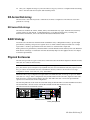
The following illustrations show the XR-series RAID using the F6412E RAID controller and EBOD enclosures.
The F6412E RAID controller is used with the HP xw8600 and HP z800 Workstations only.
XR RAID Enclosure with F6412E RAID Controller
0
0
!
FACTORY
USE ONLY
!
FACTORY
USE ONLY
Hardware RAID Controllers
Battery Backup Units
XR-Series Disk Array | 7
XE (EBOD) Expansion Enclosure (used with F6412E RAID Controller)
0
0
1
ID
0
0
1
ID
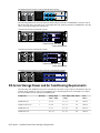
The following illustrations show the XR-series RAID using the F5412E or F5402E RAID controllers and an
EBOD enclosure that is used with both. An XR RAID enclosure using the F5412E or F5402E RAID controller
can be used with all supported workstations.
XR RAID Enclosure with F5412E RAID Controller
Hardware RAID Controllers
Battery Backup Units
XR RAID Enclosure with F5402E RAID Controller
Hardware RAID Controllers
Battery Backup Units
XE (EBOD) Expansion Enclosure (used with F5412E or F5402E RAID Controller)
XR-Series Storage Power and Air Conditioning Requirements
The following table summarizes the power consumed by XR-series storage solutions and the heat they can
generate from continuous access by your application. For detailed specifications, including noise output,
see the documentation provided by the manufacturer.
Component
Quantity
Startup Amps
(120V / 240V)
Cont' Amps (120V Watts
/ 240V)
Heat
(BTUs)
XR RAID Enclosure
1
5.5 / 2.8
3.0 / 1.5
360
1228.68
XE Expansion Enclosure
1
5.5 / 2.8
2.5 / 1.3
300
1228.68
XR RAID with 1 XE
-
11 / 5.5
5.5 / 2.8
660
2252.58
XR RAID with 2 XE
-
16.5 / 8.3
8.0 / 4.0
960
3276.48
8 | Chapter 2 Autodesk Stone Direct Storage Configurations
You must be able to meet the startup power requirements and have a climate control system with the capacity
to maintain the temperature of these components during continuous access. Refer to the following table for
standard conversion benchmarks and an example of how they are used to establish climate control
requirements.
Unit Conversion
Example
1 Watt = 3.413 BTU
360 Watts = 1228.68 BTU
12000 BTU = 1 Ton of air conditioning
1228.68 BTU = 1.024 Ton of air conditioning
XR-Series Storage Power and Air Conditioning Requirements | 9
10
Safety and Work
Environment Guidelines
3
Topics in this chapter:
■
■
■
■
■
About These Guidelines on page 11
Setting Up Your Work Site and Handling Storage Hardware on page 11
Establishing Ideal Environmental Conditions on page 12
Avoiding Electrostatic Discharge on page 12
Powering Up and Down on page 12
About These Guidelines
This chapter presents essential precautions you should review prior to installing and configuring your Stone
Direct storage. These considerations and site preparations will help ensure a safe installation.
WARNING All safety and work environment guidelines presented in this chapter relate to Stone Direct disk arrays
only and do not replace or modify guidelines or requirements set by the manufacturers of the workstation or of
the peripheral devices attached to your system.
Setting Up Your Work Site and Handling Storage Hardware
Guidelines for setting up your workspace and handling your storage hardware are included in the
documentation for your disk array.
For XR-series disk arrays, refer to Chapter 2, “Getting Started” in the XR/XE RAID Solution Maintenance Guide.
11
Establishing Ideal Environmental Conditions
The following guidelines describe the ideal environmental conditions for your disk array to function properly.
Ensure these conditions are met:
■
Room temperature and ambient humidity are at acceptable levels.
■
The disk array is at room temperature before operating.
■
The environment is clean and dust-free.
■
Disk array fans are not obstructed. Do not drape anything, such as a jacket or blanket, over any part of
the system.
■
There is good air circulation.
■
The environment has minimal vibration and humidity.
■
Electromagnetic noise is minimal by separating digital data and power cables from analog audio cables
and running them in different cable ducts.
■
The power requirements of the system are met by your electrical installation.
■
Any cable ties you use to bundle cables together are slack enough to prevent damage to the wires inside
the cables, and any loops in optical cables are relaxed enough to prevent damage to the optical fibres
inside the cables (for example, no smaller than two centimeters in diameter). Damage to wires or optical
fibres can render cables unstable or completely unusable.
Avoiding Electrostatic Discharge
By eliminating the possibility of electrostatic discharge, you ensure a safe work environment. As well, disk
array components are less likely to be damaged. The following safety guidelines minimize the possibility of
electrostatic discharge.
■
Power your system on and off according to the procedures in the section Powering Up and Down on
page 12.
■
Using a grounded static wrist strap, attach the strap's alligator clip to any grounded metal surface on the
disk array enclosure and place the wristband on your wrist.
■
Stand on a conductive rubber mat.
■
Do not handle the boards for the disk arrays or workstations unnecessarily.
■
Read and observe warning labels on enclosures and drives.
■
Call Customer Support for repair/replacement of disk drives or circuitry within the enclosure by using
one of the methods listed in Contacting Customer Support on page 3.
NOTE The power supplies for all Stone Direct disk arrays are universal, and therefore automatically detect the
correct voltage for your country.
Powering Up and Down
Powering your system up or down should be done in a proper sequence. This will ensure that the system
functions properly.
12 | Chapter 3 Safety and Work Environment Guidelines
WARNING It is critical that you follow the correct sequence when powering your system up and down to ensure
proper operation of the storage configuration. An incorrect sequence can mean your system does not recognize
all drives.
To power up your system:
1 Power up all disk arrays.
Power on the RAID controller units last. This ensures the RAID controllers detect the other units in the
Stone Direct storage.
2 Wait about 90 seconds for all the drives to spin up.
3 Power up your workstation.
To power down your system:
1 Power down your workstation. If you are on a Linux system, in a Terminal, as root, type:
shutdown -g0
2 Wait for your workstation to shut down completely and power off. If the system does not power off
automatically, power it off manually.
3 Power down your disk arrays.
Power off the RAID units first. This ensures the RAID controllers can always detect the other units in
the Stone Direct storage.
Powering Up and Down | 13
14
Workstation Connections
4
Topics in this chapter:
■
■
■
■
■
■
Understanding the Diagrams on page 15
Cabling for 2- and 4-Port Fibre Channel Adapters on page 16
HP z800 on page 16
HP xw8600 on page 17
HP xw9400 on page 18
HP xw8400 on page 20
Understanding the Diagrams
The diagrams in this chapter illustrate the fibre channel connections on the back panel of the workstation,
and the corresponding connection on the storage enclosure. Note the following about the diagrams:
■
If both 2-loop and 4-loop configurations are available for a workstation, both are illustrated in the same
diagram. If you are configuring a 2-loop configuration, ignore the connections for the second storage
assembly. For an explanation of 2-loop and 4-loop configurations, and “first storage assembly” and
“second storage assembly” references, see About 2-Loop and 4-Loop Configurations on page 23.
■
Labels for fibre channel ports correspond to the default port numbers assigned by the operating system.
For example, on a 4-port fibre channel adapter, the left-most port is port 1 and the right-most port is
port 4; the corresponding labels on the diagram are “FC Loop 1” and “FC Loop 4”.
■
The diagrams in this chapter illustrate only one fibre channel adapter or fibre channel adapter combination
per workstation. In cases where the diagram does not reflect your fibre channel adapter configuration,
refer to Cabling for 2- and 4-Port Fibre Channel Adapters on page 16 to determine which ports to connect
to storage.
15
Cabling for 2- and 4-Port Fibre Channel Adapters
Workstations may be equipped with either or both 2-port and 4-port fibre channel adapters, depending on
the storage configurations available for that workstation. If the diagram for your workstation does not reflect
your fibre channel adapter configuration, use the following to determine which ports to connect to storage:
■
If the diagram illustrates a 4-port adapter and yours is a 2-port adapter, the illustration should show
connections for only the two innermost ports of the four ports. Ignore the two outermost ports and cable
according to the two innermost ports.
■
If the diagram illustrates a 2-port adapter, and yours is a 4-port adapter, connect the two innermost ports
to Stone Direct storage as indicated in the following diagram. Note that with a 4-port adapter you can
connect the two outermost ports to archiving devices, or to a Storage Area Network (SAN) system.
Depending on your configuration, it may also be possible to connect all four ports to a SAN.
FC loop 2
To storage assembly
FC loop 3
FC Adapter
FC loop 4
To archiving device or SAN
FC loop 1
Terminating 4-Port Fibre Channel Adapters
If you are not using the two outermost ports of a 4-port fibre channel adapter, it is recommended that you
terminate these ports using the FC loopback couplers that shipped with your system. Terminating these
ports significantly decreases the time required to boot the system.
HP z800
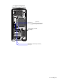
The following diagram illustrates 2-loop and optional 4-loop connections for the HP z800 workstation. The
same diagram can be used for the Lustre Media Server.
NOTE Terminate unused ports on a 4-port adapter using FC loopback couplers.
16 | Chapter 4 Workstation Connections
{
(Optional) To archiving device or SAN
{
FC loop 2
To storage assembly
FC loop 3
{
FC loop 4 (Optional) To storage (4 loop),
FC loop 1 archiving device or SAN
HP xw8600
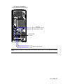
The following diagram illustrates 2-loop and optional 4-loop connections for the HP xw8600 workstation.
The same diagram can be used for the Lustre Media Server.
NOTE Terminate unused ports on a 4-port adapter using FC loopback couplers.
HP xw8600 | 17
{
FC loop 3
To storage assembly
FC loop 2
{
FC loop 1 (Optional) To storage (4 loop),
FC loop 4 archiving device or SAN
(Optional): To archiving device or SAN
HP xw9400
The first of the following diagrams illustrates 2-loop and optional 4-loop connections for a Visual Effects
and Finishing configuration running on the HP xw9400 workstation. The second diagram illustrates 2-loop
and optional 4-loop connections for a Lustre Media Server running on the HP xw9400 workstation.
NOTE Terminate unused ports on a 4-port adapter using FC loopback couplers.
18 | Chapter 4 Workstation Connections
HP xw9400 Workstation
Visual Effects and Finishing
(Optional)
FC loop 1
To second storage assembly,
FC loop 4
archiving device or SAN
{
ATTO Celerity FC-44ES
FC adapter
FC loop 3
To first storage assembly
FC loop 2
HP xw9400 | 19
HP xw9400 Workstation
Incinerator Lustre Media Server
(Optional)
FC loop 1
To second storage assembly
FC loop 4
ATTO Celerity FC-44ES FC adapter
FC loop 3
To first storage assembly
FC loop 2
ATTO Celerity FC-44ES FC adapter
{
(Optional)
To archiving device or SAN
HP xw8400
The following diagrams illustrate 2-loop (and optional 4-loop) connections for a Lustre (Windows)
configuration on the HP xw8400 workstation.
NOTE Terminate unused ports on a 4-port adapter using FC loopback couplers.
20 | Chapter 4 Workstation Connections
HP xw8400 Workstation
Lustre (Windows Configuration)
(Optional)
FC loop 1
To second storage assembly,
FC loop 4 archiving device or SAN
{
ATTO FC-44ES
FC adapter
FC loop 3
To first storage assembly
FC loop 2
NOTE HP xw8400 workstations running Lustre (Linux) with Autodesk Incinerator® do not support direct attached
storage.
HP xw8400 | 21
22
Storage Connections
5
Topics in this chapter:
■
■
■
About 2-Loop and 4-Loop Configurations on page 23
XR-Series Storage Connections on page 24
Disconnecting and Reconnecting Storage on page 29
About 2-Loop and 4-Loop Configurations
A storage assembly consists of the enclosure directly connected to your workstation, and any additional
enclosures daisy-chained to that enclosure. Each workstation-to-storage fibre channel connection is referred
to as a “loop”. A 2-loop configuration consists of one storage assembly. A 4-loop configuration consists of
two storage assemblies unless using the F6412E RAID controller, which uses one storage assembly.
The diagrams using F5402E or F5412E RAID controllers in this guide refer to “first” and “second” storage
assembly. In a 2-loop configuration, “first” storage assembly refers to the only one in the configuration. In
a 4-loop configuration, the “first” storage assembly is the one on the left of the diagram, and the “second”
is the one on the right.
NOTE It is important to cable exactly as illustrated in the diagrams and explained in the text to ensure storage
functions properly. For example, do not reverse fibre channel connections for first and second enclosures, or
reverse individual workstation-to-storage connections.
The following diagram summarizes the information in this section.
23
First storage assembly
Second storage assembly
To FC adapter on workstation
To FC adapter on workstation
To FC adapter on workstation
To FC adapter on workstation
XR RAID Enclosure
XR RAID Enclosure
Enclosure
connected
to workstation
XE (EBOD) Expansion Enclosure
XE (EBOD) Expansion Enclosure
XE (EBOD) Expansion Enclosure
XE (EBOD) Expansion Enclosure
Additional
enclosures
2-loop configuration
4-loop configuration
XR-Series Storage Connections
The XR-series provides both 2-loop and 4-loop hardware RAID configurations.
2-Loop Hardware RAID Configurations
This diagram illustrates how to cable a 2-loop hardware RAID storage configuration. Solid lines represent
cabling for the simplest 2-loop configuration (a single RAID enclosure). Dotted lines represent cabling for
additional enclosures (up to four EBOD enclosures). The table below the diagram lists the hardware you
need to cable different sizes of this storage configuration.
NOTE Although the diagram displays an XR RAID enclosure with F5412E RAID controllers and corresponding XE
(EBOD) expansion enclosures, the concept of wiring would be the same if using an XR RAID enclosure with F6412E
RAID controllers.
24 | Chapter 5 Storage Connections
To FC adapter on workstation
To FC adapter on workstation
XR RAID Enclosure
XE (EBOD) Expansion Enclosure
XE (EBOD) Expansion Enclosure
XE (EBOD) Expansion Enclosure
XE (EBOD) Expansion Enclosure
Cabling for additional enclosures
NOTE A 2-loop configuration using the F5402E and F5412E RAID controllers supports a maximum of four expansion
enclosures. The F6412E RAID controller supports a maximum of seven expansion enclosures.
Number of
RAID Units
Number of XE (EBOD) Expan- Number of fibre
sion Units
optic LC cables
Number of SFP
Number of SFP
transceiver modules 0.5 m interLC
chassis cables
F5402E, F5414E, and F6412E RAID Controllers
1
0
2
2
0
1
1
2
2
2
2-Loop Hardware RAID Configurations | 25
Number of
RAID Units
Number of XE (EBOD) Expan- Number of fibre
sion Units
optic LC cables
Number of SFP
Number of SFP
transceiver modules 0.5 m interLC
chassis cables
1
2
2
2
4
1
3
2
2
6
1
4
2
2
8
F6412E Controller only
1
5
2
2
10
1
6
2
2
12
1
7
2
2
14
NOTE When using two ATTO cards the first ATTO card is be connected to local storage and the second optional
ATTO card to a SAN and/or archiving device.
NOTE 4 Gb storage configurations require 4 Gb SFP transceivers. A label on 4 Gb SFP transceivers differentiates
them from 2 Gb transceivers (which do not have labels). Mixing 2 Gb SPFP tranceivers with 4 Gb SFP transceivers
may cause unpredictable results.
4-Loop Hardware RAID Configurations
These diagrams illustrate how to cable enclosures in a 4-loop hardware RAID storage configuration.
■
The first illustrates the cabling when using an XR RAID enclosure with F6412E RAID controllers.
■
The second illustrates the cabling for all other 4-loop configurations.
In the diagrams, solid lines represent cabling for the simplest 4-loop configuration and dotted lines represent
cabling for additional enclosures. In 4-loop configurations with two storage assemblies, you can have either
two or four additional enclosures.
The table after the diagrams lists the hardware you need to cable different sizes of this storage configuration.
26 | Chapter 5 Storage Connections
To FC adapter on workstation
To FC adapter on workstation
To FC adapter on workstation
To FC adapter on workstation
XR RAID Enclosure (F6412E)
!
0
FACTORY
USE ONLY
!
0
FACTORY
USE ONLY
XE (EBOD) Expansion Enclosure
0
0
1
0
1
ID
0
ID
XE (EBOD) Expansion Enclosure
0
0
1
0
1
ID
0
ID
XE (EBOD) Expansion Enclosure
0
0
1
0
1
ID
0
ID
XE (EBOD) Expansion Enclosure
0
0
1
0
1
ID
0
ID
Cabling for additional enclosures
4-Loop Hardware RAID Configurations | 27
First storage assembly
Second storage assembly
To FC adapter on workstation
To FC adapter on workstation
To FC adapter on workstation
To FC adapter on workstation
XR RAID Enclosure
XR RAID Enclosure
XE (EBOD) Expansion Enclosure
XE (EBOD) Expansion Enclosure
XE (EBOD) Expansion Enclosure
XE (EBOD) Expansion Enclosure
Cabling for additional enclosures
NOTE A 4-loop configuration for Visual Effects and Finishing systems supports a maximum of two expansion
enclosures per RAID controller. A 4-loop configuration for Lustre (Windows) or Incinerator supports a maximum
of four expansion enclosures per RAID controller.
To FC adapter on workstation
To FC adapter on workstation
To FC adapter on workstation
To FC adapter on workstation
XR RAID Enclosure
XE (EBOD) Expansion Enclosure
Cabling for additional enclosures
Number of
RAID Units
Number of XE (EBOD) Number of fibre optic Number of SFP trans- Number of SFP 0.5
Expansion Units
LC cables
ceiver modules LC
m inter-chassis
cables
F5402E and F5414E RAID Controllers
2
0
4
4
0
2
2
4
4
2
28 | Chapter 5 Storage Connections
Number of
RAID Units
Number of XE (EBOD) Number of fibre optic Number of SFP trans- Number of SFP 0.5
Expansion Units
LC cables
ceiver modules LC
m inter-chassis
cables
2
4
4
4
4
F6412E RAID Controller only
1
1
4
4
2
1
3
4
4
6
1
5
4
4
10
1
7
4
4
14
NOTE 4 Gb storage configurations require 4 Gb SFP transceivers. A 4 Gb SFP transceiver is differentiated from a
2 Gb transceiver by its label, which is not present on the 2 Gb transceiver.
Disconnecting and Reconnecting Storage
After you configure your storage, you must ensure that cable connections do not change. If you must
disconnect storage at any time, be sure to note which cables connect to which ports prior to disconnecting
the cables so that you can re-establish the correct connections.
Disconnecting and Reconnecting Storage | 29
30
6
Internal Storage
Connections
Topics in this chapter:
■
■
About Internal Storage on page 31
HP 8400 on page 32
About Internal Storage
This chapter describes how to connect internal storage on workstations that support internal storage. Only
Autodesk-supplied hard disks can be used for internal storage.
WARNING Connecting internal storage requires work inside the workstation enclosure. Wear a grounding strap
to ensure you do not inadvertently damage components as you work inside the enclosure. Also, Internal drives
require adequate ventilation, always close the side cover of the workstation before you boot the system.
I/O and Playback Limitations
The following limitation applies to internal storage configurations.
Platform
I/O
Playback Limitation
HP 8400
SD, HD
Single-stream HD only (no cross-dissolve in Autodesk® Smoke®)
31
Setting Up Internal Storage
After you install your Visual Effects and Finishing application on the workstation, use the Stone and Wire
sw_config utility to set up the Stone filesystem and manage the internal storage on the workstation. For
information about this utility, see the latest Stone and Wire Filesystem and Networking Guide.
Protecting Data on Internal Storage
You normally protect data on a Stone filesystem using hardware RAID. However, these features are not
available for workstations using the internal storage configuration. Because disk failure may result in media
loss, apply the following recommendations to protect media while working on the workstation:
■
Do not store critical or long-term projects on the internal storage of the workstation.
■
Ensure media used in projects is backed up and can be recaptured, if necessary.
■
Save projects and project archives to a network drive that is backed up on a regular basis.
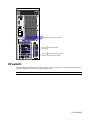
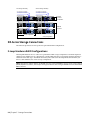
HP 8400
Internal storage is available on the HP 8400 workstation. The internal storage configuration uses four 300
GB Serial Attached SCSI (SAS) storage disks inside the system enclosure. These disks are connected to a SAS
adapter separate from the system disk. The system disk is a Serial Advanced Technology Attachment (SATA)
disk.
NOTE Unique SAS identification numbers are automatically assigned to the hard disks used for internal storage.
It is not necessary to set jumpers on SAS hard disks.
32 | Chapter 6 Internal Storage Connections
System Disk
SATA Adapter
Terminator
Ribbon cable
300 GB Storage Disk
SAS ID 1
300 GB Storage Disk
SAS ID 0
SAS Adapter 1:
-2 data drives
-300 GB each
SAS Adapter 1
U320 Adapter 1
SAS Adapter 2:
SAS Adapter 2
-2 data drives
-300 GB each
SAS ID 0
300 GB Storage Disk
SAS ID 1
300 GB Storage Disk
Ribbon cable
Terminator
HP 8400 | 33
34
LUN Management
Guidelines
7
Topics in this chapter:
■
■
■
About LUN Configuration on page 35
XR-Series LUN Creation Using the XR Configuration Utility on page 36
Accessing the RAID Controllers on page 37
About LUN Configuration
The first step after connecting new storage to your workstation is to configure logical volumes (LUNs).
■
If this is a first time setup of the RAID controllers for XR-series storage, refer to Connecting to the RAID
Controller for the First Time on page 38.
■
If your RAID controller is already connected and configured to your network, then proceed to XR-Series
LUN Creation Using the XR Configuration Utility on page 36.
NOTE RAID configurations are designed and tested by Autodesk to provide optimal performance for media
playback on your workstation. Although the RAID management utility (Stone Storage Manager for the XR-series)
lets you customize LUN configuration manually, deviating from the documented LUN configuration processes
contained in the chapter is not supported.
Once the LUNs are created and configured, you must create a filesystem on your storage. See the application
installation and configuration guide for details.
35
XR-Series LUN Creation Using the XR Configuration Utility
To create the LUNs on your XR-series storage, you must use the XR configuration utility that automates the
LUN creation process.
The XR configuration utility is used with either Visual Effects and Finishing systems installed on Red Hat
Enterprise Linux or Lustre systems installed on Windows XP SP1.
NOTE Although XR-series LUN creation is now performed by the XR configuration utility, you can monitor the
LUN creation process by accessing the RAID controllers and launching the Stone Storage Manager (SSM) RAID
management utility. To launch SSM, refer to Accessing the RAID Controllers. However, it is not necessary to launch
SSM for LUN configuration using the XR configuration utility.
Configuring LUNs with the XR Configuration Utility
The procedure in this section configures LUNs on XR-series storage for the following system types.
Filesystem
Application(s)
Platform
XFS
Autodesk® Inferno®, Flame®, Flint®, Smoke 2008 and above
Linux
XFS
Autodesk Lustre Incinerator LMS/AMS 2007 and above
Linux
NTFS
Autodesk Lustre 2007 and above
Windows
Stone FS
Autodesk® Inferno®, Flame®, Flint®, Smoke 2007 and above
Linux, up to RHEL
WS 4u3
NOTE Stone FS is not supported on Red Hat Enterprise Linux 5
NOTE For systems having 2XR or 2XR + 2XE, you have to configure one XR at a time with the XR Configuration
Utility. Connect the first XR and use the utility to configure. When done, disconnect the first XR and connect the
second XR. When the second XR is configured re-connect the two XRs.
To configure LUNs on XR-series storage:
1 Download the latest XR Configuration Utility from the Autodesk FTP site:
ftp://ftp.discreet.com/pub1/release/Utilities/XR_Configurator_v1.4.zip
2 Unzip the file locally to your workstation.
3 Open a command line interface:
■
On a Linux system, open a Terminal.
■
On a Windows system, open a Command Prompt.
4 In the Terminal or Command Prompt, launch the LUN configuration utility.
On Linux, go to the /XR_Configurator directory where the file was unzipped and type:
./XR_config.pl
On Windows, go to the \XR_Configurator directory where the file unzipped and type:
XR_config.exe
The script determines the operating system of the workstation on which it is running and detects
whether a LUN configuration exists on the storage attached to that workstation.
5 If a LUN configuration already exists on the storage, you are prompted for confirmation to overwrite
that configuration.
36 | Chapter 7 LUN Management Guidelines
WARNING LUN configuration is destructive. Make sure you want to overwrite an existing configuration
before you confirm.
6 After the script detects the number of enclosures and drives, it prompts you to indicate the filesystem
your storage configuration uses. Use the following table to determine the number to enter.
Enter:
To select:
0
Clear Configuration
1
Stone FS:
Stone FS for NON CXFS-Attached Visual Effects and Finishing Workstation. (StoneFS DAS only) (4096B
sector size)
2
Others:
Stone FS for CXFS-Attached Visual Effects and Finishing Workstation. (StoneFS DAS to be connected to a
SAN) (512B sector size)
XFS for NON CFXS-Attached Visual Effects and Finishing Workstation. (XFS DAS) (512B sector size)
XFS for Incinerator Lustre Media Server. (XFS DAS) (512B sector size)
XFS for Lustre Linux Workstation. (XFS DAS) (512B sector size)
NTFS for Lustre Windows Workstation. (NTFS DAS) (512B sector size)
x
Exit Configuration Utility
The XR configuration utility will exit without configuring your storage if any of the following parameters
are detected:
■
An incorrect number of disks. The total number of disks must be a multiple of 12.
■
Each enclosure must have the correct firmware.
■
In a dual RAID enclosure environment, there must be an equal number of expansion chassis on each
RAID enclosure. The script would have to be run with a single RAID enclosure connected at a time.
If the XR configuration utility encounters any of these parameters, it will exit.
Rescanning New LUNs from the Host Operating System
Newly-created LUNs must be rescanned by the host operating system to associate the proper disk devices
with each LUN.
To rescan LUNs:
1 Reboot the system.
2 To verify the new LUNs were detected, examine the content of the file /proc/scsi/scsi.
3 You can also see the current configuration by using the following command:
./XR_config.pl -status
Accessing the RAID Controllers
If your RAID controller is already connected and configured on your local network, you can launch the
Stone Storage Manager RAID management utility by pointing a Web browser (Internet Explorer, Firefox®,
etc.) to http://<ip adress>:9292.
Rescanning New LUNs from the Host Operating System | 37
If your RAID controller is not yet connected and configured on your local network, see Connecting to the
RAID Controller for the First Time on page 38.
Connecting to the RAID Controller for the First Time
Before you can connect to the RAID controller on your local network for the first time, you must set or
change its IP address. Each of the two RAID controllers in an XR RAID enclosure has its own IP address; you
can configure LUNs by connecting to either of the two. The factory default IP address of RAID controller 0
(the bottom controller) is 10.1.1.5. For RAID controller 1 (the top controller) the factory default IP address
is 10.1.1.6.
Connect the second Ethernet port on your workstation to the Ethernet port of RAID controller 0 (you may
require a twisted pair cat5 cable).
Then set the second Ethernet interface on your workstation to 10.1.1.x.
Launch the Stone Storage Manager RAID management utility by pointing a Web browser at the IP address
of the RAID controller, from your workstation. For example: firefox http://10.1.1.5:9292.
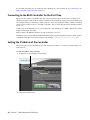
Setting the IP Address of the Controller
Once you are in Stone Storage Manager, you can change its IP address to one that is consistent with your
local network.
To set the IP address of the controller:
1 In the Stone Storage Manager, click Settings.
2 Select the Preferences tab.
38 | Chapter 7 LUN Management Guidelines
3 Enter hostname and IP information and click APPLY.
Setting the IP Address of the Controller | 39
40
Recommended Inode
Ratios for XR-Series
A
Topics in this chapter:
■
■
■
■
About This Appendix on page 41
About Inodes and Inode Ratios on page 41
Recommended Inode Ratios for 146 GB Drives on page 42
Recommended Inode Ratios for 300 GB Drives on page 43
About This Appendix
NOTE This appendix applies to the Stone filesystem only. The new HP z800 workstations running under Red Hat
Enterprise Linux 5 do not support Stone FS storage.
The tables in this appendix provide recommended inode ratios for single resolution workflows on XR-series
storage. If you are using a mixed resolution workflow with XR-series storage, use the inode value for the
lowest resolution. For example, if you use NTSC and HD resolutions in your workflows, use the inode ratio
value for NTSC.
About Inodes and Inode Ratios
An inode is a data structure that holds information about a single frame stored in a Stone partition. Each
frame in your clip library is identified by a single inode in the Stone partition.
When you set up your Stone filesystem, you must enter an inode ratio that is used to calculate the total
number of inodes available per Stone partition. For example, you might have one inode for every 2048 KB
of filesystem space. If you have an 8TB filesystem, this would provide you with 4 million inodes, and therefore,
the possibility of storing 4 million frames.
41
The default inode ratio is 2048. The minimum value is 512 and the maximum value is 6656. The inode ratio
is rounded up to the nearest 512 KB multiple (i.e. 513 rounds up to 1024). Generally, the number of inodes
is related to the frame size of your most common production format and the size of your Stone partition.
NOTE The maximum size of a Stone filesystem is 8 terabytes.
For help entering the inode ratio parameter during storage configuration, refer to the chapter “Creating the
Stone Filesystem” in the Stone and Wire Filesystem and Networking Guide.
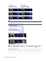
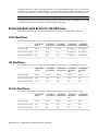
Recommended Inode Ratios for 146 GB Drives
The tables in this section provide inode ratio information for XR-series arrays with 146 GB drives.
NTSC Workflows
The values in this table are for NTSC 10-bit workflows with a frame size of 1399680 bytes at 30 fps.
Single XR Enclosure
+ 1 XE Expan- + 2 XE Expan- + 3 XE Expan- + 4 XE Expansion Enclosure sion Enclosures sion Enclosures sion Enclosures
Usable space (GB)
1367.4
2734.8
4102.2
Not supported
Not supported
Recommended inode ratio
1024
1024
1024
Not supported
Not supported
Hours of footage (hh:mm)
9:42
19:25
29:08
Not supported
Not supported
HD Workflows
The values in this table are for 1080i 10-bit HD workflows with a frame size of 8294400 bytes at 30 fps.
Single XR Enclosure
+ 1 XE Expan- + 2 XE Expan- + 3 XE Expansion Enclosure sion Enclosures sion Enclosures
+ 4 XE Expansion Enclosures
Usable space (GB)
1367.4
2734.8
4102.2
5469.6
6837.0
Recommended inode ratio
2560
3072
3072
3072
3072
Hours of footage (hh:mm)
1:38
3:16
4:55
6:33
8:12
2K Film Workflows
The values in this table are for 2K 10-bit workflows with a frame size of 12746752 bytes at 24 fps.
Single XR Enclosure
+ 1 XE Expan- + 2 XE Expan- + 3 XE Expansion Enclosure sion Enclosures sion Enclosures
+ 4 XE Expansion Enclosures
Usable space (GB)
1367.4
2734.8
4102.2
5469.6
6837.0
Recommended inode ratio
4096
4096
4096
4608
4608
Hours of footage (hh:mm)
1:19
2:40
4:00
5:19
6:40
42 | Appendix A Recommended Inode Ratios for XR-Series
4K Film Workflows
The values in this table are for 4K 10-bit workflows with a frame size of 50899872 bytes at 24 fps.
2 XR Enclosures
+ 2 XE Expan- + 4 XE Expan- + 6 XE Expansion Enclosure sion Enclosures sion Enclosures
+ 8 XE Expansion Enclosures
Usable space (GB)
2734.8
5469.6
8204.4
10939.2
13674.0
Recommended inode ratio
6144
6144
6144
6144
6144
Hours of footage (hh:mm)
0:40
1:20
2:00
2:40
3:20
Recommended Inode Ratios for 300 GB Drives
The tables in this section provide inode ratio information for XR-series arrays with 300 GB drives.
NTSC Workflows
The values in this table are for NTSC 10-bit workflows with a frame size of 1399680 bytes at 30 fps.
Single XR Enclosure
+ 1 XE Expan- + 2 XE Expan- + 3 XE Expan- + 4 XE Expansion Enclosure sion Enclosures sion Enclosures sion Enclosures
Usable space (GB)
2764.48
5528.96
8293.44
Not supported
Not supported
Recommended inode ratio
1024
1536
2560
Not supported
Not supported
Number of frames
2118594
3774438
3396994
Not supported
Not supported
Hours of footage (hh:mm)
19:37
34:57
31:27
Not supported
Not supported
HD Workflows
The values in this table are for 1080i 10-bit HD workflows with a frame size of 8294400 bytes at 30 fps.
Single XR En- + 1 XE Expan- + 2 XE Expan- + 3 XE Expan- + 4 XE Expanclosure
sion Enclosure sion Enclosures sion Enclosures sion Enclosures
Usable space (GB)
2764.48
5528.96
8293.44
11057.92
13822.41
Recommended inode ratio
2048
2048
4096
4096
4096
Number of frames
357663
714621
1071980
1426494
1784874
Hours of footage (hh:mm)
3:18
6:37
9:55
13:12
16:32
4K Film Workflows | 43
2K Film Workflows
The values in this table are for 2K 10-bit workflows with a frame size of 12746752 bytes at 24 fps.
Single XR En- + 1 XE Expan- + 2 XE Expanclosure
sion Enclosure sion Enclosures
+ 3 XE Expan- + 4 XE Expansion Enclosures sion Enclosures
Usable space (GB)
2764.48
5528.96
8293.44
11057.92
13822.41
Recommended inode ratio
4096
4096
4096
4096
4096
Number of frames
232710
465121
698130
929049
1161312
Hours of footage (hh:mm)
2:42
5:23
8:05
10:45
13:26
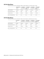
4K Film Workflows
The values in this table are for 4K 10-bit workflow with a frame size of 50899872 bytes at 24 fps.
2 XR Enclosures
+ 2 XE Expan- + 4 XE Expan- + 6 XE Expan- + 8 XE Expansion Enclosure sion Enclosures sion Enclosures sion Enclosures
Usable space (GB)
2764.48
5528.96
8293.44
11057.92
13822.41
Recommended inode ratio
4096
4096
4096
4096
4096
Number of frames
58206
116392
174616
232710
291027
Hours of footage (hh:mm)
0:40
1:21
2:01
2:42
3:22
44 | Appendix A Recommended Inode Ratios for XR-Series
Index
A
air conditioning, requirements
P
8
power, requirements 8
powering on or off, sequence for
C
conventions, in users guide
customer support
contacting 3
2
R
RAID
enclosures 7
strategy 7
D
documentation
set of guides
S
3
E
EBOD enclosures 7
electrostatic discharge, avoiding
environmental conditions, ideal
12
12
F
fibre channel adapters
cabling 16
terminating 4-port
12
shutdown sequence 12
software RAID 7
static electricity discharge, avoiding
Stone Direct, defined 5
storage, handling 11
support
contacting 3
12
T
terminology
1
16
H
handling storage 11
hardware RAID 7
I
inode and inode ratios, defined 41
inode ratios, recommended 42–43
internal storage, limitations 31
U
users guide
conventions
2
W
workflow, storage configuration
6
X
XR-Series
configurations
defined 7
24
45 | Index
46