1
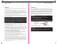
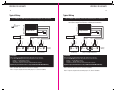
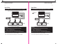
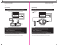
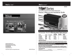
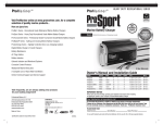
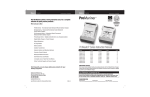
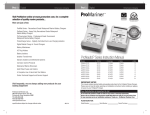
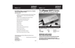
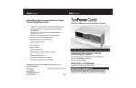
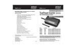
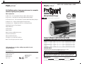
ProMa r i ne r
ProMa r i ne r
TM
TM
H E AV Y D U T Y R E C R E AT I O N A L S E R I E S
Visit ProMariner online at www.promariner.com, for a complete
selection of quality marine products...
Here are just a few:
ProMar1 Series - Recreational Grade Waterproof Marine Battery Chargers
Marine Battery Charger
ProSport Series - Heavy Duty Recreational Grade Marine Battery Chargers
ProMar Digital Performance Charging Inside
100%
WATERPROOF &
SALTWATER
TESTED
ProTournament Series - Professional Grade Tournament Grade Marine Battery Chargers
ProNauticP Series - Sailing and Cruising Marine Battery Chargers
ProIsoCharge Series - Digitally Controlled Zero Loss Charging Isolators
Digital Mobile Charge In-Transit Chargers
Battery Maintainers
AC Plug Holders
Battery Isolators
Galvanic Isolators and Monitored Systems
Corrosion Control Products
Waterproof Marine Binoculars
2-Year Warranty
A Complete Line of Hand Held Test Meters
Owner's Manual and Installation Guide
Online Technical Support and Service Support
Model
Part No.
Volts
Amps
Banks
Cables
Size
AC In
ProSport6
ProSport8
43006
43008
12
12/24
6
8
1
2
6’
6’/6’
7.125”x 7.25” x 2.75”
8.375”x 7.25” x 2.75”
90-135
90-135
ProSport12
43012
12/24
12
2
6’/6’
9.875”x 7.25” x 2.75”
90-135
12/24/36
15
3
6’/6’/6’
10.825”x 7.25” x 2.75”
90-135
ProSport15 (OEM only) 43015
Visit frequently, we are always adding new products for your
boating enjoyment!
Made in China
43020
12/24
20
2
6’/6’
12.125”x 7.25” x 2.75”
90-135
ProSport20 Plus
43021
12/24/36
20
3
6’/6’/6’
12.125”x 7.25” x 2.75”
90-135
IMPORTANT NOTICE
Please save and read all safety, operating and installation instructions before installing
or applying AC power to your ProSport On-Board Marine Battery Charger.
Professional Mariner, LLC
PO. Box 968
Rye, New Hampshire 03870
TEL: 603-433-4440
FAX: 603-433-4442
www.promariner.com
ProSport20
specifications subject to change without notice
Design and Constructed to:
Marine UL 1236 SB
CSA C22.2 No. 107.2
FCC Class A
ABYC A-28
Your Satisfaction is Important to Us!
Do not return this product to a retailer or dealer for any service or warranty requirements.
Please call our Customer Care Department at 800-824-0524 from 8:30 am to 5pm Eastern Time
for any warranty, service or installation assistance. Thank you - ProMariner Customer Care
10/12 A
PLEASE RECORD YOUR:
Model Number:
Serial Number:
Date of Purchase:
For use with Flooded (Lead-Acid), AGM and Gel Batteries. Not for use with 4D or 8D large capacity batteries.
INTRODUCTION
0
1
Table of Contents
Introduction...
Introduction
1
CAUTIONS, WARNINGS AND SAFETY INSTRUCTIONS…
2-3
General Overview…
4-5
General Operation…
6-8
Installation...
Wiring Diagrams…
Thank you from all of us at ProMariner and congratulations on your recent purchase of the ProSport
On-Board Marine Battery Charger. Powered and designed by ProMariner, a leader in the marine
charger industry for over 30 years. The Generation 3 ProSport has been taken to the next level
of performance. Each model fully utilizes state of the art all digital microprocessor controlled
charging technology, delivering industry leading features not seen in our previous generation of
marine battery chargers. Features include: digital bank trouble indicators, once a month storage
reconditioning mode and expanded digital LED display.
9-11
11-18
Charging your Batteries...
19
Maintenance…
20
Troubleshooting...
21
Accessories...
22
Warranty Information...
23
Important Charger Operation Note:
Once your new ProSport is installed and properly connected to batteries you will be ready to plug it in.
Please note the ProSport has a built-in self test feature that will also analyze all battery connections
and batteries to determine your boats batteries are capable of being charged correctly. The self
test is automatic and will take place everytime the unit is plugged into a 110VAC outlet. The self
test may take up to 2 minutes to complete.
During the self test the red charge mode indicator will be flashing. When completed if everything
is connected properly and the batteries are OK and above 2.0 volts DC then the charger will
register and illuminate the green system check OK indicator followed by a solid (non flashing)
red charge mode LED illuminating indicating all batteries are being charged.
If the charger does not go into the charge mode with a solid (non flashing) red charge mode
indicator and the system check OK indicator is not illuminated with a solid green LED then a
red battery bank fault LED will illuminate identifying the battery(s) that have either a wiring
fault present i.e poor connection, a blown DC cable fuse, the DC cable is wired in reverse
polarity, battery cable is wired across two batteries in series with a high DC overvoltage of
24V or the battery itself may be under 2.0 volts DC. In any of these cases refer to the
troubleshooting section on page 21 of this manual.
ProMariner’s Generation 3 ProSport Features Include:
ProMar Digital Technology
Microprocessor and software controlled pulse charging technology delivering a 40% lighter
design, cooler charger operation and faster charging.
System Check OK and Battery Bank Trouble Status Indicators
Advanced technology eliminates time consuming troubleshooting by clearly indicating
system and battery connections are OK or if a fault is present on a specific battery bank.
Digital Multi-Stage Performance Charging
Fully charge and extend the life of your batteries. Automatically charges, conditions and
safely maintains all batteries on board for maximum time on the water.
Storage Recondition Mode
During short or long-term storage, ProSport automatically reconditions all batteries on
board once a month for maximum battery life and performance.
Distributed On-Demand™ Technology
ProMariner’s Distributed-On-Demand™ Technology automatically senses and distributes
100% of available charging amps to any one bank or combination of all banks. All unused
charging amps are Distributed-On-Demand™ to batteries on board requiring additional
charging amps.
Digital LED Display and Battery Type Selector
LED indicators for charging, conditioning and maintain modes in addition to AC power and
selected battery type (2 charge profiles to choose from with a 3rd profile for AGM HP on
the ProSport 20 Dual model only. )
Built-in Quality & Safety
Compact and rugged extruded aluminum design, dual in-line DC safety fuses for trolling
motor battery banks. Built-in over-voltage, overload, over-temperature, reverse polarity and
ignition protection.
Pre-wired for Easy Installation
2-Year Warranty
SAFETY INSTRUCTIONS
SAFETY INSTRUCTIONS
3
2
General Safety Instructions
General Safety Instructions
Before connecting your batteries or applying AC power, read all instructions and cautionary
markings on the battery charger, cables, and batteries.
CAUTION - To reduce the risk of injury, charge only lead-acid type rechargeable batteries;
Flooded (lead-acid), Sealed (lead-acid), Gel (Gelled Electrolyte Lead-acid) and AGM (Absorbed
Glass Mat). Other types of batteries may burst, causing personal injury. The ProSport is
factory set for standard Flooded (lead-acid) /AGM (Absorbed Glass Mat) batteries.
Use of attachments not recommended or sold by Professional Mariner, LLC may result in a
risk of fire, electrical shock or personal injury.
EXTERNAL CONNECTIONS TO CHARGER SHALL COMPLY WITH THE UNITED STATES COAST
GUARD ELECTRICAL REGULATIONS (33CFR183, SUB PART 1).
Do not operate the charger if it has received a sharp blow, direct hit of force, been dropped
or otherwise damaged in any way. Do not install if any protective AC and DC cable insulation,
DC fuse holders and/or ring terminals have been damaged or compromised.
Call ProMariner for repair service to avoid risk of fire, short circuits or electrical shock.
Do not disassemble the battery charger. If service or repair is required please contact customer
care at 1-800-824-0524. Incorrect reassembly or cable modifications may result in a risk
of electrical shock, fire or explosion.
To reduce the risk of electrical shock, remove AC power from the charger prior to any
maintenance or cleaning.
WARNING: RISK OF EXPLOSIVE GASES
WORKING IN THE VICINITY OF A LEAD-ACID BATTERY IS DANGEROUS. BATTERIES GENERATE EXPLOSIVE
GASES DURING NORMAL BATTERY OPERATION. FOR THIS REASON IT IS OF EXTREME IMPORTANCE
THAT EACH TIME BEFORE USING YOUR CHARGER YOU FOLLOW THESE SAFETY INSTRUCTIONS.
WARNING AVOID SERIOUS INJURY OR DEATH FROM FIRE, EXPLOSION, OR
ELECTRICAL SHOCK
- Make your AC power connection in an open atmosphere free of explosive fumes.
- Make your AC power connection in a secure manner that will avoid contact with water.
Personal Safety Precautions
a) Someone should be within the range of your voice or close enough to come to your aid
when working near a lead-acid battery.
b) Have plenty of soap and water nearby in case battery acid comes in contact with skin,
clothes, or eyes.
c) Wear complete eye protection and clothing protection. Avoid touching eyes while working
near battery(s).
d) If battery acid contacts skin or clothing, wash immediately with soap and water. If acid
enters eye, immediately flood eye with running cold water for at least 10 minutes and get
medical attention immediately.
e) NEVER smoke or allow a spark or flame in the vicinity of a battery or engine.
f) Incorrect assembly or modification may result in risk of electrical shock, fire, or explosion.
g) Be extra cautious to reduce risk of dropping a metal tool onto the battery. It might spark
or short-circuit a battery or other electrical hardware which may cause an explosion or fire.
h) Remove all personal metal items such as rings, bracelets, necklaces, watches, and
jewelry when working near a battery. A battery can produce a short circuit current high
enough to weld a ring or any other metal, causing serious burns.
CAUTION - To reduce the risk of injury, charge only lead-acid type rechargeable batteries;
Flooded (lead-acid), Sealed (lead-acid), Gel (Gelled Electrolyte Lead-acid) and AGM (Absorbed
Glass Mat). Other types of batteries may burst, causing personal injury. The ProSport is factory
set for standard Flooded (lead-acid) /AGM (Absorbed Glass Mat) batteries.
Use your ProSport On-Board Marine Battery Charger to charge: Flooded (lead -acid)/AGM
(Absorbed Glass Mat) Gel (Gelled Electrolyte Lead-acid) Batteries. It is not intended to supply low
voltage electrical systems other than in a marine application. Do not use your marine battery charger
to charge dry cell batteries that are commonly used with home appliances. These batteries may
burst and cause injury to persons and property. Never charge a frozen battery
Safety Precautions Prior to Charging Batteries
If necessary to remove a battery from a boat to charge, always remove the grounded negative
terminal from the battery first. Make sure all accessories in the boat are off, as to not cause
an arc. Be sure the area around the charger and batteries is well ventilated while the batteries are
being charged. Gases can be forcefully blown away using a piece of cardboard or other nonmetallic
material as a fan.
Clean battery terminals with full eye protection to prevent corrosive material from coming in
contact with eyes.
Add distilled water in each cell until electrolyte reaches levels specified by the battery
manufacturer. This helps purge excessive gases from cells. Do not overfill. For batteries without
caps, carefully follow manufacturer's recharging instructions.
Study all manufacturer’s specific precautions, such as removing or not removing cell caps
while charging, in addition to battery type for proper rate of charge.
Extension cords should be industrial grade / heavy duty UL approved and grounded. Check extension
cord before use for damage, bent prongs, and cuts. Replace if damaged. Always make your extension
cord connection on the charger side first. After connecting the extension cord to the charger proceed
to plug the extension cord to a nearby 120 VAC GFCI protected (Ground Fault Circuit Interrupt) outlet.
Always remove the extension cord from the 120 VAC outlet first when charging is
completed followed by unplugging the charger from the extension cord.
IMPORTANT NOTICE: FCC CLASS A PART 15 NOTIFICATION
Your ProSport On-Board Marine Battery Charger has been designed and tested to comply with FCC Class
A part 15. These regulations are to provide adequate protection against harmful interference while
operated in a commercial application. If in a residential setting, you are encountering interference with
TV and radio reception, simply remove AC power from the ProSport to confirm if your battery charger is
causing interference. End user can explore the following to minimize interference:
1) Chose a different AC circuit to power your On-Board Marine Battery Charger.
2) Make sure your outlet is properly grounded.
3) Re-position receiving antenna.
4) Purchase a separate AC line filter.
5) Relocate charger so that it is at the furthest point from home receiving equipment,TV, radio, etc.
GENERAL OVERVIEW
GENERAL OVERVIEW
5
4
How Distributed-On-Demand™ Charging Technology Works
General Overview
The ProSport Charger is an advanced electronic and fully automatic multi-stage on-board marine
battery charger. ProSport is pre-wired for easy installation and is 100% waterproof for fresh and
salt water applications. ProSport’s multi-stage charging process delivers five modes of operation
that include: start up diagnostics, charging, conditioning, auto maintain and storage reconditioning
of each battery. This process is proven to extend the life of your batteries and will fully charge
your batteries each time you connect to AC power. ProSport delivers increased power and
performance while providing improved durability and heat transfer.
The ProSport Distributed-On-Demand™ Charging Technology will automatically sense and distribute
100% of the available charging output of 8,12, 15 or 20 amps (model specific) to any one battery
or combination of all batteries. Each battery charger output is fully isolated. ProSport’s easy to view
LED indicators will provide at a glance status of: AC power, battery type, charging, and ready status.
The LED status center also includes an indication of a fault or failure detected at each battery that
is connected to the charger and can be seen on the top of the unit when installed.
ProSport’s Distributed-On-Demand™ Charging Technology ensures 100% of the available
charging amps are fully utilized to meet the demand of each battery on-board. For example,
if your engine start battery only needs 2 amps from your ProSport 12 (6/6 two bank charger)
the unused 4 amps will be automatically Distributed-On-Demand™ to your house or trolling
motor battery, providing a total of 10 amps for faster charging versus only 5 amps that
the conventional 5/5 battery charger would provide. The competitive 5/5 charger has a 5
amp limit per bank.
Other 5/5
10 amp chargers
VS
Note: ProSport On-Board Marine Battery Chargers are designed for any combination of group
24,27,30 and 31 batteries. Each battery charger DC output cable must be connected to one (1)
12 Volt DC battery (even if batteries are configured for 24 Volt DC or 36Volt DC trolling motor or
system applications).
Group size 24
thru 31 only
cable jacket
red (+)
Top View of Battery
black (-)
+
Each charger cable must
be connected to 1 battery,
just as shown. Observe
black to (-) and red to (+).
Do this for each battery.
_
Important: The pair of red and black wires in 1 cable jacket MUST GO TO THE SAME 12VDC battery.
Not Fully Distributed
12 Amps Fully Distributed
10
2
+
5
Engine
Start Battery
2
Fully
Charged
Fully
Charged
House or
Trolling Battery
+
House or
Trolling Battery
Engine
Start Battery
When connecting to an engine start battery only connect the battery bank cable that is LABELED:
"FOR ENGINE BATTERY, USE THIS BANK CABLE ONLY".
Application Tip
If your application is for 4D or 8D large capacity batteries, please refer to ProMariner's website
www.promariner.com and view our ProNauticP Hardwired Charger Assortment for a model that
is correct for this group size of batteries.
Most specifically you do not have to remove series or parallel jumper cables to use your ProSport
charger. See typical wiring diagrams for these systems in the installation section of this manual.
Note: The ProSport must be connected to batteries to operate. It will not operate as a
12 volt power supply.
General Operation
Install your ProSport On-Board Marine Battery Charger to the guidelines in this manual.
Make sure your charger and batteries are properly vented. Connect your extension cord
with no AC power present to the ProSport and proceed to plug your extension cord in at
a nearby 120 VAC GFCI protected (Ground Fault Circuit Interrupt) outlet.
With your ProSport plugged in properly, it will automatically/ fully charge your batteries
while it conditions and extends the life of your batteries. Always leave your charger plugged
in to reduce sulfate build-up allowing your batteries to be fully charged and maintained
for your next fishing trip.
The ProSport design incorporates a new storage recondition mode that stimulates and
reconditions your onboard batteries for 3 hours once a month and when completed will
resume its normal auto maintain mode. During the storage recondition mode the ready/maintain
LED will remain green and the storage recondition mode LED will fade-in fade-out pulse,
indicating your batteries are being reconditioned and are fully charged during this process.
G E N E R A L O P E R AT I O N
G E N E R A L O P E R AT I O N
6
7
ProSport LED Status Center - Operation and Display
Operation after Applying AC Power to a ProSport Charger
Connected to Discharged Batteries
(The following example is for the factory setting of Flooded (lead-acid) batteries) When power is applied the
ProSport performs a self test of the battery charger electronics and the batteries connected to the battery charger.
During the startup test the battery type LED will be illuminated and the red charge mode LED will
flash indicating that the unit is in a self test mode. When complete and if there are no faults, the
charger's system check OK indicator will illuminate green and the ProSport's solid red charging
LED will be ON indicating the charge process is initiated.
Note: If there is a fault the appropriate bank LED will illuminate and the charge process may not start, depending
on the location of the fault. See page 21 for further troubleshooting details.
ProSport includes 7 LEDs for operation status and up to 3 battery bank trouble LEDs depending
on the model.
1. The blue AC power LED
Illuminates when AC power is applied
2. The battery type LED
Will illuminate red for standard Flooded (lead-acid)/AGM and green for GEL.
Note: The ProSport 20 Dual bank model includes an amber battery type LED for AGM HP
(High Performance) battery type. Please read the battery manufacturer literature carefully
and select the correct charge profile. Failure to do so may cause early battery failure.
3. The system check OK LED
After applying AC power the ProSport will self test and analyze all battery connections
and batteries. If all checks are OK the green LED will illuminate. This can take up to 2 minutes.
4. The charge mode LEDs
Charging:
Red LED will flash during the self test and battery test mode
(approximately 1-2 minutes) and will be solid red during charging.
Conditioning:
Amber LED illuminates during conditioning mode.
Ready / maintain:
Green LED illuminates when batteries are fully charged and being
automatically maintained until you are ready to use your boat.
Storage recondition: Green LED fades in and out when performing a once a month storage
recondition mode.
If There are no Battery Faults, the Green System Check OK LED will Illuminate and the
Following Sequences will Proceed:
The red battery type LED (factory set for standard Flooded (lead-acid)/AGM batteries) will illuminate.
The red charge mode LED will illuminate indicating the charger has started its multi-stage charging process.
When the charge process is approximately 80% complete the red charge mode indicator will
turn off and the amber conditioning LED will turn on indicating the conditioning mode.
When the multi-stage charge process is completed you will observe the following:
Battery type red LED goes OFF.
The red charging LED and the amber conditioning LED will be off and the green ready/maintain
LED will illuminate indicating your batteries are fully charged.
The only LEDs on after the multi-stage charge process is completed are the green system
OK LED, blue AC power LED and the green ready/maintain LED.
Multi-Stage Charging Overview
ProSport Charging: During this mode the “Charging” indicator will be red. ProSport will use all of its
available charging amps (as controlled by temperature) until the battery voltage is raised to 14.6VDC
(Flooded lead-acid factory setting).
ProSport Conditioning: During this mode the “Conditioning” status indicator will be amber. Batteries will
hold at 14.6 VDC (factory set for Flooded lead-acid batteries) to complete charging while conditioning each
battery connected. Upon completion the ProSport will go into its maintain mode.
ProSport Ready / Maintain: During this mode the “Ready/Maintain” status indicator will be green and remain
on with the blue “power” LED indicating that your batteries are fully charged while being maintained at a precision
13.4 volts (factory set for Flooded lead-acid batteries) and are ready to go when you are.
ProSport Storage Recondition Mode: During this mode the ProSport “Recondition Mode” green indicator
will illuminate with a slow fade in and out pulse indicating that while your batteries/boat are in storage the
ProSport will automatically recondition all batteries for up to 3 hours once a month extending battery life
and maximizing on the water battery power performance.
Average Voltage
14.6V
5. Battery bank trouble status LEDs
Red LEDs will illuminate indicating a wiring problem or fault at one of the batteries connected
to the ProSport charger. See page 21 for further details.
14
13.4V
13
Volts
12
Charging
Conditioning
11
(Factory installed black programming cap charge profile illustration).
Ready/ Maintain
Monthly Storage Reconditioning
G E N E R A L O P E R AT I O N
I N S TA L L AT I O N
8
9
Selecting a Charging Profile & Understanding Battery Types
Installation
Your battery charger is equipped with a user programmable battery type selector that is factory
set for standard Flooded (lead-acid) / AGM (Absorbed Glass Mat) batteries.
All ProSport Battery Chargers are designed to be permanently mounted on-board, and should
be mounted with extruded fins placed horizontally.
Always mount your ProSport in a compartment area that can be properly ventilated during use.
Do NOT mix battery types on-board. All batteries should be of the same age and in good
operating condition.
Do NOT make any electrical connections to the ProSport or batteries until the following steps
are completed:
10 Easy to follow installation steps:
1. Select a mounting location that allows for free air ventilation with a minimum of 8 inches of
clear unobstructed space around and in front of the ProSport On-Board Marine Battery Charger.
Open all battery and engine compartments and ventilate for at least 15 minutes before starting
the installation of the ProSport charger. Confirm all battery cables can reach each of the batteries.
To set your charger for Gel batteries simply remove the black programming cap and replace
it with the Gel programming gray cap. If you own a ProSport 20 Dual Bank Charger you also
have the option to use the High Performance AGM profile recommended for OPTIMA BlueTop
Deep Cycle and Odyssey AGM marine batteries by installing the blue AGM HP programming
cap. Any time you reprogram or change the cap, apply marine silicone to the threads of the
cap being installed.
NOTE: AGM (Absorbed Glass Mat) batteries are not Gel (Gelled Electrolyte Lead-acid) batteries and
require a completely different charge profile that must be selected versus the out of the box factory
setting. AGM batteries can accept the same charging profile as Flooded (lead-acid) batteries.
Understanding Battery Types & Charger Settings
There are three primary types of batteries in the marketplace today; standard Flooded (leadacid), AGM (Absorbed Glass Mat), high performance AGM and Gel cell (Gelled Electrolyte Leadacid). Traditionally, the most common type of batteries used are Flooded (lead-acid) batteries.
Almost all Gel cell batteries will state that they are Gel cell on the battery case or labels. Shown
below are typical battery voltages at absorption and float levels.
LED color
Red
Green
Amber*
Battery Type
Standard Flooded (lead-acid) with or without fill caps
AGM (Absorbed Glass Mat) - Sealed
Gel Cell - Sealed Gray Cap
AGM High Performance
(Absorbed Glass Mat) - Sealed
(OPTIMA, Odyssey, West Marine Brands)
Charging Profile
14.6 VDC Absorption, 13.4 VDC Float
14.1 VDC Absorption, 13.8 VDC Float
14.7 VDC Absorption 13.6 VDC Float
Cap
Black
Gray
Blue*
NOTE: AGM (Absorbed Glass Mat) batteries are not Gel (Gelled Electrolyte Lead-acid) batteries and require a
completely different charge profile that must be selected versus the out of the box factory setting.
AGM batteries can accept the same charging profile as Flooded (Lead-acid) batteries.
* Only available on ProSport 20 Two Bank model only.
Note: If you are still unsure what kind of battery(s) you have, we recommend that you
contact the manufacturer of the battery(s).
Do not install charger on carpeted, upholstered, vinyl, or varnished areas. Be sure to place the
ProSport in an accessible area where all indicators are viewable. Install this unit on a hard surface.
Note: For installations requiring an extension of the DC battery charger cables, please call or visit
your retailer or dealer to purchase ProMariner’s 5 foot or 15 foot battery charger DC cable extenders.
Our innovative cable extenders are properly fused and do not require any cutting or stripping of
wires. If you have any problems locating this accessory call ProMariner at 1-800-824-0524.
2. Using the ProSport charger as a template or the enclosed paper template, mark the position
of each mounting hole. Insure the mounting screws will not puncture or protrude into a live well,
a fuel or oil tank or the bottom of the boat.
3. Using a 1/8" drill bit, drill pilot holes in the (4) marked locations as described in step 3.
Apply a silicon sealer in each of the mounting locations to waterproof the screw holes.
4. Position the ProSport over the mounting holes and secure with a power screwdriver
by installing 4 stainless steel # 10 screws. (mounting screws not included).
1/8" pilot hole
with silicon sealer
IMPORTANT NOTICE
Confirm the surface you will be
mounting the charger to is
adequate in strength and
thickness to hold the ProSport in
place with the mounting screws
you have selected.
Maintain an obstruction free area
of 8 inches around the ProSport
On-Board Marine Battery Charger
For aluminum boat installation we recommend installing your ProSport Charger on a wood
or fiberglass panel and not directly on the aluminum hull.
I N S TA L L AT I O N
WIRING DIAGRAMS
10
11
Installation
Installation
5. Prepare each battery in advance by cleaning each terminal post with a wire brush until a
shiny surface is obtained.
6. Run cables free from sharp objects and hold each in place with cable ties. Coil excess
cable, do not cut or shorten the length of the cables, as in-line fuses are located 4 inches
from the end of each red (positive) cable. In addition, there are fuses in all but one of the black
(negative) leads. These fuses protect the charger and output cables in the event of a wiring
short. We recommend the use of wire ties or cable clamps to provide strain relief for the cables
and to reduce the risk of damage to the cables or connections.
7. Connect the DC output cables as illustrated on pages 11-18. Make sure the (black) wires
are connected as illustrated to the negative side of the battery and the (red) wires are connected
to the positive side of the battery.
STEP 4: Incorrect wiring will result in reverse polarity or high reverse voltage, in the event this
happens, the ProSport Charger has been designed to not fail as a result, however it will cause
the charger to "internally disconnect" and provide "no output" until the (reverse polarity caused
by putting the "red" + lead on a - negative battery terminal) and or the (high reverse DC voltage
caused by taking one bank cable and spreading it across two batteries) is corrected, using the
wiring diagrams as shown on pages 11-18. In the event of a reverse polarity connection or an
improper battery connection or if an output is not connected to a battery the appropriate red
battery bank trouble LED will illuminate identifying the battery and wiring connections where a
fault is present. See page 21 for further details.
4 Steps to Wire your ProSport Charger Correctly
STEP 1: Simply choose the illustration that has the same number of charger output bank
cables as your ProSport Battery Charger in hand and wire exactly as shown (choose the
illustration that matches your application) for proper charger operation.
STEP 2: Do not remove your batteries series or parallel jumper cables that interconnect
batteries to each other. ProSport Chargers are designed with isolated outputs and series
or parallel jumper cables do not have to be removed.
STEP 3: Your ProSport charger will not operate properly if it is not connected properly
to each battery. Reminder, the ProSport and each DC jacketed bank cable must be
properly connected to "individual 12V batteries". Number of DC jacketed bank cables
equals the number of batteries that must be individually connected. Example: a three
bank ProSport 20 3 Bank must be connected to 3 individual 12V batteries. As Illustrated
on Pages 11-18. Select your battery / trolling motor configuration for the specific wiring
illustration need for your charger.
Each charger cable must
be connected to 1 battery,
just as shown. Observe black
to (-) and red to (+). Do this
for each battery.
black (-)
_
Important: The pair of red and black wires in 1 cable jacket MUST GO TO THE SAME 12VDC battery.
Group size 24
thru 31 only
cable jacket
red (+)
Top View of Battery
8. Make sure all DC connections are correct, tight, and free from corrosion.
9. Locate the AC power cord in an open-air area of your boat at least 21 inches from the
charger, batteries, and fuel fill lines.
10. Connect a heavy duty UL approved extension cord to the ProSport charger first. After
connecting the extension cord to the charger, proceed to plug the extension cord to a nearby
120 VAC GFCI protected (Ground Fault Circuit Interrupt) outlet. Always remove the extension
cord from the 120VAC outlet first when charging is completed, followed by unplugging the
charger. You are now connected and charging your batteries. View the LED indicators.
When connecting each jacketed battery charger cable, make sure it is connected
to only one 12 VDC battery and observe the polarity and color of all connections:
Red Wire = + (Positive) Battery connection
Black Wire = - (Negative) Battery connection
The black wire can never be connected to a terminal with red wires. Only black.
+
Important Note: Your ProSport charger will not operate properly if it is not connected properly
to each battery. Reminder, The ProSport and each DC jacketed bank cable must be properly
connected to "individual 12V batteries". Number of DC jacketed bank cables equals the number
of batteries that must be individually connected. Example: a 3 bank ProSport 20 Three Bank
charger must be connected to 3 individual 12V batteries, as illustrated on pages 11-18. Simply
choose the illustration that has the same number of charger output bank cables as your ProSport
Battery Charger in hand and wire exactly as shown (choose the illustration that matches your
application) for proper charger operation.
Installation
When connecting to an engine start battery only connect the battery bank cable that is LABELED:
"FOR ENGINE BATTERY USE THIS BANK CABLE ONLY".
Application Tip
If your application is for 4D or 8D large capacity batteries, please refer to ProMariner's website
www.promariner.com and view our ProNauticP Hardwired Charger Assortment for a model that is
correct for this group size of batteries.
WIRING DIAGRAMS
WIRING DIAGRAMS
12
13
Typical Wiring
Typical Wiring
Fig. 1 ProSport 15 (OEM only) and 20 Three Bank Charger for 3 12V Batteries
Dedicated 12 VDC Trolling/House Bank and 2 Engine Crank Batteries Typical Configuration
Fig. 2 ProSport 15 (OEM only) and 20 Three Bank Charger for 3 12V Batteries
24 VDC Trolling Motor Battery Configuration with (2) 12 VDC Batteries Connected
with a Series Jumper Plus Dedicated 12 VDC Engine Start Battery
Note:
Indicates Jumper Series
Indicates Fuse
ProSport 20 Plus
ProSport 20 Plus
+
Engine
_
Bat 2
+
Engine
_
Bat 3
+
_
Top View
of Battery
Bat 1
+
12 VDC Trolling Motor
or House Battery
_
12 VDC Engine
Crank Battery
Cable 3
black
red
Bat 2
+
_
black
Cable 2
red
red
black
Cable 1
black
Cable 3
red
black
red
Bat 1
Cable 2
red
For Engine Battery use
this Bank Cable Only
Cable 1
black
For Engine Battery use
this Bank Cable Only
Bat 3
+
_
Top View
of Battery
Two 12 VDC Batteries connected with a series
jumper for a 24 VDC Trolling Motor
Installation
Installation
When connecting each jacketed battery charger cable, make sure it is connected
to only one 12 VDC battery and observe the polarity and color of all connections:
Red Wire = + (Positive) Battery connection
Black Wire = - (Negative) Battery connection
The black wire can never be connected to a terminal with red wires. Only black.
Important: The pair of red and black wires in 1 cable jacket MUST GO TO THE SAME 12VDC battery.
Important: The pair of red and black wires in 1 cable jacket MUST GO TO THE SAME 12VDC battery.
Note 1: One bank cable connects to no more than one battery
Note 2: ProSport is designed to be used with group 24, 27, 30 and 31 batteries
Note 1: One bank cable connects to no more than one battery
Note 2: ProSport is designed to be used with group 24, 27, 30 and 31 batteries
WIRING DIAGRAMS
WIRING DIAGRAMS
15
14
Typical Wiring
Typical Wiring
Fig. 3 ProSport 15 (OEM only) and 20 Three Bank Charger for 3 12V Batteries
Dedicated 36 VDC Trolling Motor Battery Configuration
with (3) 12 VDC Batteries Connected with (2) Series Jumpers
Fig. 4 ProSport 20, 12 and 8 Dual Output Charger for 2 12V Batteries
12 VDC Engine Start and a 12 Volt Trolling Motor or House Battery Configuration
with (2) 12 VDC Batteries
Note:
Indicates Jumper Series
Indicates Fuse
ProSport 20 Plus
Bat 1
+
_
+
_
Bat 3
+
_
Cable 2
Top View
of Battery
Bat 1
+
_
12 VDC Engine
Crank Battery
Three 12 VDC Batteries connected with a (2)
series jumper for a 36 VDC Trolling Motor
black
Cable 1
red
red
Bat 2
For Engine Battery use
this Bank Cable Only
red
Cable 3
black
Cable 2
red
red
black
Cable 1
black
For Engine Battery use
this Bank Cable Only
black
ProSport 12
Bat 2
+
_
Top View
of Battery
12 VDC Trolling
Motor or House Battery
Installation
Installation
When connecting each jacketed battery charger cable, make sure it is connected
to only one 12 VDC battery and observe the polarity and color of all connections:
Red Wire = + (Positive) Battery connection
Black Wire = - (Negative) Battery connection
The black wire can never be connected to a terminal with red wires. Only black.
Important: The pair of red and black wires in 1 cable jacket MUST GO TO THE SAME 12VDC battery.
Important: The pair of red and black wires in 1 cable jacket MUST GO TO THE SAME 12VDC battery.
Note 1: One bank cable connects to no more than one battery
Note 2: ProSport is designed to be used with group 24, 27, 30 and 31 batteries
Note 1: One bank cable connects to no more than one battery
Note 2: ProSport is designed to be used with group 24, 27, 30 and 31 batteries
WIRING DIAGRAMS
WIRING DIAGRAMS
16
17
Typical Wiring
Typical Wiring
Fig. 5 ProSport 20, 12 and 8 Two Bank Charger for 2 12V Batteries
Dedicated 24 VDC Trolling Motor Battery Configuration
with (2) 12 VDC Batteries Connected with a Series Jumper
Fig. 6 ProSport 20, 12 and 8 Two Bank Charger for 2 12V Batteries in Parallel
Dedicated 12 VDC Parallel Trolling Motor or House Configuration
Note:
Indicates Jumper Series
Indicates Fuse
ProSport 12
ProSport 12
Red Jumper
For Engine Battery use
this Bank Cable Only
Cable 1
Cable 2
black
red
black
red
For Engine Battery use
this Bank Cable Only
_
Top View
of Battery
red
Cable 2
Bat 2
+
_
+
Bat 2
black
_
+
_
Bat 1
Bat 1
+
red
Cable 1
black
Black Jumper
Top View of Battery
Two 12 VDC Batteries connected with a series
jumper for a 24 VDC Trolling Motor
Installation
Installation
When connecting each jacketed battery charger cable, make sure it is connected
to only one 12 VDC battery and observe the polarity and color of all connections:
Red Wire = + (Positive) Battery connection
Black Wire = - (Negative) Battery connection
The black wire can never be connected to a terminal with red wires. Only black.
When connecting each jacketed battery charger cable, make sure it is connected
to only one 12 VDC battery and observe the polarity and color of all connections:
Red Wire = + (Positive) Battery connection
Black Wire = - (Negative) Battery connection
The black wire can never be connected to a terminal with red wires. Only black.
Important: The pair of red and black wires in 1 cable jacket MUST GO TO THE SAME 12VDC battery.
Important: The pair of red and black wires in 1 cable jacket MUST GO TO THE SAME 12VDC battery.
Note 1: One bank cable connects to no more than one battery
Note 2: ProSport is designed to be used with group 24, 27, 30 and 31 batteries
Note 1: One bank cable connects to no more than one battery
Note 2: ProSport is designed to be used with group 24, 27, 30 and 31 batteries
WIRING DIAGRAMS
C H A R G I N G Y O U R B AT T E R I E S
18
19
Charging your Batteries
Typical Wiring
Fig. 7 ProSport 6 One Bank Charger for 1 12V Battery
Dedicated 12 VDC Trolling Motor, House or Engine Battery Configuration
Note:
Indicates Jumper Series
Indicates Fuse
ProSport 6
red
black
Cable 1
Bat 1
+
_
Top View
of Battery
12 VDC Battery
Installation
When connecting each jacketed battery charger cable, make sure it is connected
to only one 12 VDC battery and observe the polarity and color of all connections:
Red Wire = + (Positive) Battery connection
Black Wire = - (Negative) Battery connection
The black wire can never be connected to a terminal with red wires. Only black.
Important: The pair of red and black wires in 1 cable jacket MUST GO TO THE SAME 12VDC battery.
Note 1: One bank cable connects to no more than one battery
Note 2: ProSport is designed to be used with group 24, 27, 30 and 31 batteries
The ProSport Charger is designed to charge, condition, maintain and recondition your batteries.
Please follow these steps each time you use your ProSport charger:
1. Open all battery compartments and ventilate for at least 15 minutes before applying AC
power to your charger. While charging your batteries make sure to keep your battery
compartment open allowing for free air ventilation.
2. Make sure all DC battery connections are tight and clean. Follow battery manufacturer's
recommendations for battery cell caps. (loosen caps if applicable).
Once your new ProSport is installed and properly connected to batteries you will be
ready to plug it in.
3. Connect a heavy duty UL approved extension cord to the ProSport charger first. After
connecting the extension cord to the charger, proceed to plug the extension cord to a nearby
120 VAC GFCI protected (Ground Fault Circuit Interrupt) outlet.
4. Assuming your batteries are discharged, and your ProSport is factory set (black programming
cap installed) for standard Flooded (lead-acid) batteries, you should observe ProSport's self
test mode (flashing red charge mode LED), blue AC power LED turn on, followed by the red
battery type LED turning on (red is the factory setting of standard Flooded (lead-acid)/AGM
type batteries) and once the green system check OK LED turns on you will notice a solid red
charge mode indicator identifying the charging process has started.
Note: The ProSport has built in self testing to insure all batteries are connected correctly. The self test
is automatic and will take place everytime the unit is plugged into a 110 VAC outlet. The self test may
take 2 minutes to complete. During the self test the LED will flash indicating it is in self test mode. If
everything is connected properly and the batteries are OK the charger’s system check OK indicator will
illuminate green and the ProSport will then go into its charge mode indicated by a solid red LED.
If the charger does not go into the charge mode and a red "fault" LED is illuminated then make
sure your batteries have a voltage greater than 2 volts DC present and refer to the trouble shooting
section on page 21.
5. The multi-stage charging process is complete when only the green LED for the ready/maintain
mode is illuminated and the blue AC power LED remain on indicating that your batteries are
fully charged and are being maintained with a precision 13.4 volts DC finishing voltage
(Factory set charge profile for standard Flooded (lead-acid / AGM batteries).
6. When you are ready to use your boat, unplug your extension cord at the GFCI outlet
first, followed by unplugging the charger.
Optional Battery Bank Status Monitor
See your local dealer or retailer for the ProMariner Remote Battery Bank Status Monitor. The
remote monitor is easy to install and connects directly to your boat’s batteries. Once installed,
simply hold down the "push-to-test" button and observe the charge level indicator for each
battery (up to 3 batteries can be monitored).
Note: AC power to the battery charger and the boat’s engine must be off when using the
Remote Battery Bank Status Monitor.
TROUBLESHOOTING
TROUBLESHOOTING
20
21
Maintenance
Item:
Process:
When:
Item:
Process:
When:
Item:
Process:
When:
Item:
Process:
When:
Troubleshooting
Battery Connections
Clean and tighten all battery connections. Follow battery manufacturer's
instructions for cleaning a battery. Clean all battery terminals with a wire brush
where required and tighten all battery connections.
Monthly
Battery Electrolyte
Per battery manufacturer’s instructions, monitor, and maintain proper
levels of distilled water in each battery.
Monthly
ProSport DC Output Wiring
Visually inspect all wiring for cuts and abrasions. Contact ProMariner if
your charger needs to be serviced.
Monthly
AC Power Cord and Mounting Hardware Inspection
Visually inspect the AC power cord. Confirm ground blade is present and
all plug blades are in good condition and not bent out of place.
Check all mounting hardware to ensure there is no loose hardware.
Tighten where required.
Monthly
No Blue AC Power LED or Charge Mode Indicator or Battery Type LED
Check for loss of AC power at the 120 VAC outlet. Confirm GFCI (Ground Fault Circuit
Interrupter) has not tripped. Check with a meter or 120 VAC test light that AC power is present
at the end or your extension cord. Reset AC power if it was not present. Confirm all charger
cables are installed with the correct polarity connections at each battery and that all connections
are clean and tight. Wait 2 minutes while unit performs self test. If AC power is present and
all connections are correct and LEDs do not illuminate, contact ProMariner at 1-800-8240524 from 8:30 am to 5pm Eastern Time. If your ProSport is within the warranty period of
2 years from the date of purchase, you can go to www.promariner.com where you will find
our customer care return form and instructions.
Green System Check OK Indicator is OFF & a Red Battery Bank Trouble Status LED is ON.
Identify the battery bank LED that is lit, remove AC power and check the battery bank indicated i.e 1, 2, 3
(model specific). The LED indicates there is a fault present. Listed below are typical faults and what can be
done to clear the red battery bank trouble status indicator (reapply AC power after making any corrections):
Poor battery connections - Make sure all connections are tight and clean
Blown DC cable fuse - Make sure all fuses are good with a digital ohm meter
or continuity tester and visually inspect the ProSport's DC battery cables to insure they
have not been compromised or shorted in any way.
Reverse polarity - Make sure all wiring connections are color coded and connected
properly and that each bank cable goes to one 12V battery where (+) = red (-) = black.
Battery too low to charge - with a digital voltmeter make sure the battery is over
2.0 volts DC (if not have your battery charged out of the boat and have it load tested
by your local battery dealer to insure optimum performance on the water.
High battery voltage input - Check to make sure one bank lead was not spread across 2 batteries
connected in series for 24 volts DC. If so correct by wiring to the diagrams on pages 11- 18.
Battery(s) not charging, Blue AC Power LED, RED Charging & Battery Type LEDs are ON
Confirm all charger cables are installed with the correct polarity connections at each battery,
and that all connections are clean and tight. Confirm that there are no bank trouble status
LED indicators on. With the charger on, read DC voltage at each battery. If any of the readings
are less than 13 volts DC proceed with the following:
A. Disconnect AC power at the 120 VAC outlet.
B. Go to pages 11-18 of this manual and confirm your ProSport model charger
is connected correctly as illustrated in the installation drawings.
C. Upon completing B above; plug your charger into AC power and observe the LED center.
Charger should be in the charging mode (charge status indicator should be red). If after
completing a full charge cycle, 10-12 hours or more for deeply discharged or completely dead
batteries, the charge mode indicator should be green as well as the blue AC power LED.
Note: If a Digital Volt Meter (DVM) is available to you, instead of waiting to complete a full charge cycle, you can simply use a
DVM and take DC voltage measurements across each 12 volt battery. As long as the voltage continues to increase while the
red charging LED is on, this will serve as a confirmation that the charger is properly connected and is properly charging.
TROUBLESHOOTING
WA R R A N T Y
22
23
Specifications
Warranty
model
part no.
voltage
amps
ProSport 6
ProSport 8
ProSport 12
ProSport 15 (OEM only)
ProSport 20
ProSport 20Plus
43006
43008
43012
43015
43020
43021
12
12/24
12/24
12/24/36
12/24
12/24/36
6
8
12
15
20
20
max. no. batteries
1
2
2
3
2
3
cable size
size L x W x H
weight
AC in
6’
6’/6’
6’/6’
6’/6’/6’
6’/6’
6’/6’/6’
7.125”x 7.25” x 2.75”
8.375”x 7.25” x 2.75”
9.875”x 7.25” x 2.75”
10.825”x 7.25” x 2.75”
12.125”x 7.25” x 2.75”
12.125”x 7.25” x 2.75”
2 lbs
3 lbs
4 lbs
6 lbs
5 lbs
6 lbs
90-135
90-135
90-135
90-135
90-135
90-135
WARRANTY CARD CAN BE REGISTERED AT WWW.PROMARINER.COM
or the warranty card included in this manual can be completed and sent to ProMariner by mail.
PROSPORT LIMITED TWO-YEAR FACTORY WARRANTY
Each ProSport model is guaranteed against defects in material and workmanship to the
original consumer in normal use for 2 years from the date of purchase. Professional Mariner,
LLC will at it's discretion repair or replace free of charge any defects in material or workmanship.
Accessories
ProSport 1.5 Battery Maintainers
Fully automatic, with built-in safety.
LED status indicator, 1-year warranty
10115
10116
51201
51202
Remote Battery Bank Status Monitor
Remote "Push to Test" status indicators for up to 3 batteries
with easy to read LED indicators. Universal flush or surface
mount capable.
51060
Purchase or other acceptance of the product shall be on the condition and agreement that
Professional Mariner, LLC SHALL NOT BE LIABLE FOR INCIDENTAL OR CONSEQUENTIAL
DAMAGES OF ANY KIND. (Some states do not allow the exclusion or limitation of incidental
or consequential damages, so the above limitations may not apply to you.) This warranty is
made in lieu of all other obligations or liabilities on the part of Professional Mariner. Professional
Mariner neither assumes nor authorizes any person for any obligation or liability in connection
with the sale of this product.
Battery Bank Cable Extenders
No cutting, stripping, or splicing wires! 2 convenient sizes to
choose from: 5’ or 15’. Gold plated terminals, in line fuses
and hardware included.
51070 & 51071
Hand Held Digital Multi-Meter
Test and measure AC and DC voltage and amperage, continuity,
resistance fuses outlets and more. Large digital LCD display with
back light and hold feature. Test leads included.
87730
Model
Handheld DC System Tester
Remote Battery Bank Status Monitor for up to 3 Batteries
ProMariner’s AC Plug Holder (white)
ProMariner’s AC Plug Holder (black)
Universal AC Plug Holder (black)
Universal AC Plug Holder (white)
15’ Battery Bank Cable Extender
5’ Battery Bank Cable Extender
Hand Held Digital Multi-Meter
To place an order contact your local retailer, dealer or ProMariner at:
603-433-4440 / Fax: 603-433-4442 / www.promariner.com
The following conditions apply:
• Warranty and repair adjustment calculated from manufacture date if not
registered or proof of purchase within two weeks of sale.
• Warranty void if unauthorized repairs attempted.
• Deep water damage not covered under warranty
• Customer is responsible for shipping to ProMariner.
• Cosmetic repairs are done at the owner’s request and expense.
ProMariner & Universal Plug Holders
Secure your AC plug with an easy to mount plug holder. No
cutting or stripping of wires required. Safe and easy to use.
Choose from two colors, black or white.
We are committed to customer satisfaction and value your business. If at any time during
the warranty period you experience a problem with your new ProSport On-Board Marine
Battery Charger, simply call us at 1-800-824-0524 for technical support or email
[email protected].
Part No.
87710
51060
51200
51201
51202
51203
51070
51071
87730
To make a claim under warranty, go to www.promariner.com and click on the support tab and
follow the instructions making sure to identify the product and the problem. If you can not use
our online warranty claim registration, please feel free to call ProMariner at the toll free number
listed below. Professional Mariner will make its best effort to repair or replace the product, if
found defective within the terms of the warranty, within 30 days after return of the product to
the company. Professional Mariner will ship the repaired or replaced product back to the
purchaser. This warranty gives you specific legal rights, and you may also have other rights,
which vary from state to state. This warranty is in lieu of all others expressed or implied.
Factory Service Center & Technical Support
Professional Mariner, LLC
200 International Drive, STE 195
Portsmouth, NH 03801.
Tel: 1-800-824-0524
Professional Mariner, LLC
Tel: (603) 433-4440 / Fax: (603) 433-4442
25
24
Notes
Notes