1
20U-FS1
CU20FS1
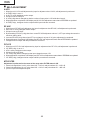
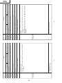
Ë SELF ADJUSTMENT
H-VCO
1.
2.
3.
4.
5.
6.
7.
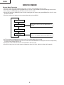
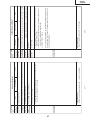
When there is H-VCO self-adjustment key input for adjustment item H-VCO, self-adjustment is performed.
H-FREE(1chip) is set to 1.
H-OUT is set by intelligent monitor output.
IM input is set as TIM input.
H-VCO(1chip) data is changed so that the number of input pulse is 125 inside 8ms interval.
When adjustment completed, OSD display and H-VCO self-adjustment status data of EEPROM are updated.
H-FREE(1chip), intelligent monitor output and IM input mode are recovered.
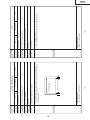
RF-AGC
1.
2.
3.
4.
When there is RF-AGC self-adjustment key input for adjustment item RF-AGC, self-adjustment is performed.
AGC-OUT is set by intelligent monitor output.
IM input is set as AD input.
By decreasing RF-AGC (1chip) data from current RF-AGC adjustment value to 0, AFT input voltage becomes the
maximum setting value.
5. Increase RF-AGC(1chip) data, when AFT input voltage is at (max. 0.3V) point, adjustment is completed.
6. When adjustment completed, OSD display and RF-AGC self-adjustment status data of EEPROM are updated.
7. Intelligent monitor output and IM input mode are recovered.
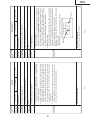
PIF-VCO
1.
2.
3.
4.
5.
6.
7.
When there is PIF-VCO self-adjustment key input for adjustment item PIF-VCO, self-adjustment is performed.
VIF-DEF(1chip) is set to 1.
AFC is set by intelligent monitor output.
IM input is set as AD input.
VIF-VCO(1chip) data is changed so that input voltage becomes 2.5V.
When adjustment completed, OSD display and PIF-VCO self-adjustment status data of EEPROM are updated.
VIF-DEF(1chip), intelligent monitor output and IM input mode are recovered.
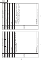
MTS-FILTER
Adjustment is performed in the center of the range when FILTER status is OK.
1. If data is changed from 0 to 63, point where NG → OK is A and point where OK → NG is B.
2. If data is changed from 63 to 0, point where NG → OK is C and point where OK → NG is D.
3. (A+B+C+D)/4 is the adjustment point.
10