Download Wolf Sub-Zero 648PROG Installation guide
Transcript
INSTALLATION GUIDE PRO 48 Refrigeration Contents Important Note PRO 48 Refrigeration . . . . . . . . . . . . . . . . . . . . . . . . . . . . 3 To ensure the safe and efficient installation of Sub-Zero equipment, please take note of the following types of highlighted information throughout this guide: PRO 48 Specifications . . . . . . . . . . . . . . . . . . . . . . . . . . . 4 PRO 48 Site Preparation . . . . . . . . . . . . . . . . . . . . . . . . . . 5 PRO 48 Installation . . . . . . . . . . . . . . . . . . . . . . . . . . . . . . 8 IMPORTANT NOTE highlights information that is especially relevant to a problem-free installation. Service Information . . . . . . . . . . . . . . . . . . . . . . . . . . . . . 18 CAUTION signals a situation where minor injury or product damage may occur if instructions are not followed. Features and specifications are subject to change at any time without notice. Visit subzero.com/specs for the most up-todate information. WARNING states a hazard that may cause serious injury or death if precautions are not followed. IMPORTANT NOTE: Throughout this guide, dimensions in parentheses are millimeters unless otherwise specified. PRO 48 Refrigeration 3 subzero.com/specs Sub-Zero PRO 48 Refrigeration Before You Start The importance of the installation of the Sub-Zero PRO 48 unit cannot be overemphasized. Installation should be done by a qualified installer. Make sure the opening dimensions, door and drawer clearances, electrical service and plumbing are correct for the model you are about to install. Refer to specifications on the following pages. Before you begin the installation process, it is recommended that you read this entire installation guide. There are key details that you should take special care to observe during the installation. By reading these instructions carefully, you will make the installation process easier, problem-free and most importantly, safe. The installation process is identical for both the model 648PROG which features a glass door on the upper refrigerator compartment and model 648PRO with a solid door. Any questions or problems regarding the installation should be directed to your authorized Sub-Zero dealer or Sub-Zero customer service at 800-222-7820. You may also check the contact & support section of our website, subzero.com. Important product information, including the model and serial number of your unit are listed on the product rating plate. The rating plate is located on the left side of the top freezer drawer compartment (drawer must be open). Refer to the illustration below. TOOLS AND MATERIALS REQUIRED • Appliance dolly able to support 1000 lbs (454 kg) and adequate manpower to handle the weight of the unit. • Phillips and slotted screwdrivers. • Torx drive screwdriver set • Allen, standard and crescent wrenches. • Various sized pliers. • 7/16" hex bolt nut driver. • Cordless drill and assorted drill bits. • Level—2' (.6 m) and 4' (1.2 m) recommended. • 4' (1.2 m) of 1/4" copper tubing and saddle valve for water line (do not use self-piercing valves). • Copper tubing cutter. • Masonite, plywood, pressed fiberboard, cardboard or other suitable material to protect finished flooring. • Appropriate materials to cover and protect the home and furnishings during installation. RATING PLATE Location of rating plate (open drawer). PRO 48 Specifications 4 Overall Dimensions MODELS 648PRO AND 648PROG 25 7/8" (657) 48" (1219) 84" (2134) 42 1/8" (1070) 30 1/2" (775) 4" (102) HEIGHT DIMENSIONS ± 1/2" (13) 30 3/16" (767) 23 7/8" (606) 14 1/2" 21" (533) (368) SPECIFICATIONS 30 3/4" (781) Capacity / Weight INTERIOR CAPACITY 648PRO and 648PROG SHIPPING WEIGHT 2 3/8" (60) 648PRO 648PROG R CU FT (L) F CU FT (L) 18.4 (521) 11.7 (331) LBS (KG) 860 (390) 875 (397) PRO 48 Site Preparation 5 subzero.com/specs Opening Dimensions STANDARD AND FLUSH BUILT-IN INSTALLATIONS TOP VIEW OPENING DEPTH OPENING DEPTH OPENING WIDTH OPENING HEIGHT SIDE VIEW Opening Dimensions FRONT VIEW Standard Flush Opening Width 47 1/2" (1206) 48" (1219) Opening Height 83 3/4" Opening Depth (2127) 84 1/8" (2137) 24" (610) 26" (660) IMPORTANT NOTE: For standard built-in installations, the face frame of the unit will extend 2" (51) beyond cabinetry. In flush built-in installations, the front of the face frame will be flush with surrounding cabinetry. 
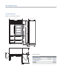
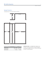
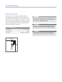
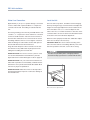
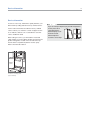
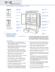
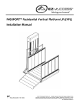
PRO 48 Site Preparation 6 Electrical Requirements For PRO 48 models, the electrical supply should be located within the shaded area shown in the illustration below. Follow the National Electrical Code and local codes and ordinances when installing the receptacle. A separate circuit, servicing only this appliance is required. A ground fault circuit interrupter (GFCI) is not recommended and may cause interruption of operation. Do not use an extension cord or two-prong adapter. Do not remove the power supply cord ground prong. Electrical Requirements Power Supply The outlet must be checked by a qualified electrician to be sure that it is wired with the correct polarity. Verify that the outlet is properly grounded. 115 V AC, 60 Hz Circuit Breaker 15 amp Receptacle 3-prong grounding-type FRONT VIEW 7" (178) E 6" (152) 75 1/2" (1918) FROM FLOOR Location of electrical supply. Always shut power off at the circuit breaker before performing any installation, service or maintenance. PRO 48 Site Preparation 7 subzero.com/specs Plumbing Requirements The PRO 48 has an automatic ice maker with an integrated water filtration system. The water supply line should be located within the shaded area shown in the illustrations. The water line must not interfere with installation of the anti-tip bracket. Plumbing Requirements 1/4" Water Supply Line Water Pressure 35–120 psi (2.4–8.3 bar) Excess Water Line for Connection The water supply line should be connected to the house supply with an easily accessible shut-off valve between the supply and the unit. Do not use self-piercing valves. A saddle valve kit is available through your authorized Sub-Zero dealer. A reverse osmosis system can be used, provided there is constant water pressure of 20 psi (1.4 bar) to 120 psi (8.3 bar) supplied to the unit at all times. In this application, the water filtration system must be bypassed. Refer to water filter bypass mode on page 16. IMPORTANT NOTE: All installations must meet local plumbing code requirements. It is not recommended that the ice maker be connected to a softened water supply. Water softener chemicals, such as salt from a malfunctioning softener, can damage the ice maker and lead to poor ice quality. If a softened water supply cannot be avoided, make sure that the water softener is well maintained and operating properly. IMPORTANT NOTE: Do not use with water that is microbiologically unsafe or of unknown water quality without adequate disinfection before or after the system. Systems certified for cyst reduction may be used on disinfected waters that may contain filterable cysts. OD copper line 36" (914) BACK WALL 18" (457) 1/2" (13) 6" (152) 18" (457) 6" (152) 3" (76) FLOOR FRONT VIEW Location of water supply— rear. TOP VIEW Location of water supply— bottom. PRO 48 Installation 8 Anti-Tip Bracket Installation To prevent the PRO 48 from tipping forward and provide a stable installation, the unit must be secured in place with the anti-tip bracket provided with the unit. IMPORTANT NOTE: Placement of the anti-tip bracket is critical to a stable installation. Failure to properly position the anti-tip bracket will prevent it from engaging the unit. The anti-tip bracket must be installed exactly 26" (660) from the front of the face frame of the unit to the back of the anti-tip bracket. Also, the centering line on the lower flange of the anti-tip bracket must be centered in the rough opening. Make sure the anti-tip bracket is installed on a solid base. Refer to the illustration below. To properly secure the anti-tip bracket for a stable installation, use all anti-tip bracket hardware as instructed for wood or concrete floors. IMPORTANT NOTE: For either wood or concrete floor applications, if the wood screws do not hit a wall stud in any of the upper holes on the anti-tip bracket, use the provided #8–18 x 11/4" wood screw, #12 flat washer and nylon zip-it wall anchor in its place. IMPORTANT NOTE: In some installations the subflooring or finished floor may necessitate angling the screws used to fasten the anti-tip bracket to the back wall. Make sure there are no electrical wires or plumbing in the area which the screws could penetrate. Anti-Tip Bracket Hardware 1 12 3 12 Anti-tip bracket. Anti-tip bracket #12 x 2 1/2" PN HD wood screws 3/8" x 3 3/4" Trubolt anchors #12 flat washers 3 #8–18 x 11/4" AB PH HD screws 3 Nylon zip-it wall anchors PRO 48 Installation 9 subzero.com/specs Anti-Tip Bracket Installation WOOD FLOOR APPLICATIONS INSTALL CONCRETE WEDGE ANCHORS: Use the twelve #12 x 2 1/2" wood screws and the twelve #12 flat washers provided. Drill pilot holes 3/16" (5) diameter maximum and make sure the screws penetrate through the flooring material and into the wall plate a minimum of 3/4" (19). Make sure the screws hold tight. Refer to the illustration below. 1) Drill a 3/8" (10) diameter hole any depth exceeding the minimum embedment. Clean the hole or continue drilling additional depth to accommodate drill fines. Use a carbide drill bit manufactured within ANSI B94.12-77. CONCRETE FLOOR APPLICATIONS Use the three 3/8" x 3 3/4" concrete wedge anchors, six #12 x 2 1/2" wood screws and six #12 flat washers provided. Drill pilot holes 3/16" (5) diameter maximum and make sure the screws penetrate through the flooring material and into the wall plate a minimum of 3/4" (19). Then drill 3/8" (10) diameter holes into the concrete a minimum of 11/2" (38) deep. Make sure the anchors and screws hold tight. Refer to the illustration below. 2) Assemble the washer and nut flush with the end of anchor to protect threads. Drive the anchor through the material to be fastened until the washer is flush with the surface material. 3) Expand the anchor by tightening the nut 3–5 turns past hand-tight position or to 25 foot-pounds of torque. Always wear safety glasses and use other necessary protective devices or apparel when installing or working with anchors. Anchors are not recommended for use in lightweight masonry material such as block or brick, or for use in new concrete which has not had sufficient time to cure. The use of core drills is not recommended to drill holes for the anchors. 23 3/4" 23 3/4" (603) (603) 23 3/4" FINISHED FLOORING WALL PLATE SUBFLOORING WOOD FLOOR Wood floor. 23 3/4" (603) (603) FINISHED FLOORING WALL PLATE SUBFLOORING CONCRETE FLOOR Concrete floor. 11/2"(38) min PRO 48 Installation 10 Unpack the Unit Grille Removal Uncrate the PRO 48 unit and inspect for any damages. Remove the wood base and discard the shipping bolts and brackets that hold the wood base to the bottom of the unit. Remove and discard all packing materials. In order to prevent damage to the PRO 48 grille, the top grille assembly should be removed prior to moving the unit. IMPORTANT NOTE: Do not discard the kickplate, anti-tip bracket and hardware or corner protectors. These items will be needed for installation. Retract the front leveling legs all the way up to allow the unit to be moved into position more easily. You will extend the front leveling legs down and make adjustments once the unit is in position. Remove the drain pan from the base of the unit to avoid damage to the drain pan, and allow for proper placement of the appliance dolly. To remove the grille assembly, pull out on the bottom edge of the grille and tilt the grille frame forward. Disconnect the network cables which connect the exterior temperature displays on the grille to the display module. Cut the two white cable ties which attach the network cables to the right grille support and disconnect the cables. The cable ties should be replaced with the extra cable ties provided, once the unit is properly installed. Remove the three grille bolts from base of the grille and the upper grille screw. Remove the grille assembly. Refer to the illustrations below. Reverse this procedure to reinstall the grille assembly. GRILLE SCREW NETWORK CABLES GRILLE BOLT Lift grille assembly. Grille removal. PRO 48 Installation 11 subzero.com/specs Position the Unit Before moving the PRO 48 unit into position, secure doors and drawers closed and protect any finished flooring. Use an appliance dolly to move the unit near the rough opening. The PRO 48 is equipped with rollers, so it can be moved into position more easily. When securing the unit on the appliance dolly, use the corner protectors (retained from the packing materials) under the strapping to avoid damage to the stainless steel exterior. Also, secure the doors and drawers closed with the strapping. Refer to the illustration below for proper placement of the appliance dolly. IMPORTANT NOTE: The rear levelers must be in their lowest position in order to roll the unit back into the rough opening. Leveling cannot be completed until the unit is in position. Moving the PRO 48. IMPORTANT NOTE: If for any reason the unit has been laid on its back or side, you must allow the unit to stand upright for a minimum of 24 hours before connecting power. Shut off power to the electrical outlet. Plug the power cord into the grounded outlet and roll the unit into position. Make sure the anti-tip bracket is properly engaged. The PRO 48 is very heavy—885 lbs (401 kg) or 900 lbs (408 kg). Be sure to have adequate manpower when moving and positioning the unit. PRO 48 Installation 12 Water Line Connection Level the Unit Approximately 3' (.9 m) of 1/4" plastic tubing is connected to the ice maker with a preassembled 1/4" compression connection at the end. This tubing is located under the unit. Once the unit is in position, extend the front leveling legs down by turning the legs counterclockwise and adjust the height. The rear height adjustment can be made from the front of the base. Use a 5/16" socket to adjust the rear rollers. Turn the 5/16" hex bolt clockwise to raise the unit or counterclockwise to lower it. Refer to the illustration below for location of the rear roller base adjustment. The water line fitting connection kit, provided with the unit, contains a 1/4" compression sleeve and nut for connection to the household water line. Place the sleeve and nut on the water line and fasten to the connection at the end of the tubing under the unit. Do not over tighten. Check all water line fittings for leaks. Make sure the drain pan can be removed without water line interference. Purge the water line prior to final connection to the unit. This will remove any debris that may be present in the tubing from installing the new water line. IMPORTANT NOTE: If a reverse osmosis system is used, it is recommended that the water filtration system be bypassed. Refer to water filter bypass mode on page 16. When the unit is properly leveled, door and drawer adjustments are less likely to be necessary. IMPORTANT NOTE: Be sure to reference leveling of the unit to the floor and not surrounding cabinetry. This could affect the operation of the unit, such as door closing. To reduce the possibility of the unit tipping forward, the front leveling legs must be in contact with the floor. IMPORTANT NOTE: Let your customer know that the ice maker will not produce ice immediately, and that the first few batches of ice produced should be discarded. Allow 24 hours for proper ice production. IMPORTANT NOTE: Water lines must not be exposed to freezing temperatures. Exposure could cause damage to the unit and home. REAR ADJUSTMENT FRONT LEVELING LEG Rear roller base adjustment. PRO 48 Installation 13 subzero.com/specs Door Adjustment Make sure both doors of the PRO 48 are properly aligned for function and appearance. If not, adjustments can be made to the cabinet hinges. The doors of the PRO 48 are very heavy. Use care when removing them. IMPORTANT NOTE: The unit must be properly leveled before adjusting hinges. If the PRO 48 is properly installed and leveled, it may still be necessary to adjust doors left to right. Adjustments are performed at the top and/or bottom cabinet hinges. HINGE ADJUSTMENT 1) Lift up the vent portion of the top grille. 2) Remove the door by opening to approximately 90° and lifting the door off cabinet hinges. Refer to the illustration below. IMPORTANT NOTE: When adjusting hinges, it is important to keep hinges parallel to the face of the door and side of the cabinet. Excessive misalignment will result in door light switch malfunction. If the switch is not activated, the fan will not operate and lights will remain on. This will result in elevated cabinet temperatures. After hinge adjustments are made, check for proper functioning of door light switch. Refer to the illustration below. 3) Remove hinge pins. 4) Loosen the two cabinet hinge screws 1/4 to 1/2 turn. Refer to the illustration below. 5) Reinstall hinge pins and door. With the door open, using the Allen wrench provided, turn the adjustment screw to adjust the cabinet hinge. Refer to the illustration below. 6) Close the door and check alignment. If additional adjustment is required, repeat these steps until the door is properly aligned. HINGE SCREW HINGE PIN ADJUSTMENT SCREW CABINET HINGE Door removal. Hinge adjustment. LIGHT SWITCH Door light switch. PRO 48 Installation 14 Drawer Adjustment Make sure all drawers of the PRO 48 are properly aligned for function and appearance. If not, vertical and horizontal adjustments can be made to the drawers. The drawer must be removed to make vertical and horizontal adjustments. To remove the drawer, pull the drawer all the way out until it stops, lift up evenly on both sides of the drawer front and pull out. To reinstall the drawer, raise the front of the drawer and place onto the drawer slide tracks. Be sure to engage the front of the drawer slide with the drawer assembly. Make sure the drawer is fully engaged onto the tracks. Check alignment of the drawer closer. If the closer catch does not align with closer pin, adjust the position of drawer closer. VERTICAL ADJUSTMENT 1) Loosen the drawer slide mounting screws. HORIZONTAL ADJUSTMENT 1) Loosen the two front drawer slide screws. Refer to the illustration below. 2) Move adjustment blocks to desired position and tighten screws. 3) Release the rear adjustment block by disengaging the snaps. 4) Move the block forward to shift drawer to the right, and back to shift drawer to the left. Each position will move the drawer .030" (.8). Both sides should be moved in the same direction. 5) Snap the block over the pins located on the rear adjuster. Refer to the illustration below. 6) After adjustment, tighten all screws and reinstall the drawer. Check the drawer seal for proper gasket seating. 2) Using a 7/16" open-end wrench, turn the adjustment screw until proper alignment is achieved. Refer to the illustration below. 3) After adjustment, tighten all screws and reinstall the drawer. Check the drawer seal for proper gasket seating. REAR ADJUSTMENT BLOCK SLIDE SCREW MOUNTING SCREW ADJUSTMENT SCREW Vertical adjustment. Horizontal adjustment. PRO 48 Installation 15 subzero.com/specs Complete the Installation Optional Accessories INSTALL KICKPLATE 90° DOOR STOP Make sure the drain pan is in the proper position before installing the kickplate. To install, screw the kickplate to brackets attached to the inside surface of each roller base. Refer to the illustration below. The doors of PRO 48 models open to 135°. For installations where the door opening must be limited, an optional 90° door stop kit is available through your authorized Sub-Zero dealer. To obtain local dealer information, visit the find a showroom section of our website, subzero.com. IMPORTANT NOTE: The kickplate must be removable for service. The floor cannot interfere with removal. Reinstall the grille by reversing the procedure outlined on page 10. Turn power back on to the electrical outlet. KICKPLATE Kickplate installation. SIDE AND TOP PANELS For freestanding applications, stainless steel side and top panels are available through your authorized Sub-Zero dealer. Installation instructions are provided with the panels. To obtain local dealer information, visit the find a showroom section of our website, subzero.com. PRO 48 Installation 16 Water Filtration System WATER FILTER BYPASS MODE If you choose not to use the water filtration system, the system can be placed in water filter bypass mode by removing the water filter cartridge. In this mode, the water supplied to the ice maker will not be filtered and the water filter monitor will be deactivated. WATER FILTER Lift the top grille assembly to access the water filter cartridge. To lift the grille, pull out on the bottom edge of the grille and tilt the grille frame forward. Refer to the illustration. Slowly rotate the water filter cartridge one-quarter turn counterclockwise to disengage. Gently twist until the cartridge is free from the base. DO NOT pull. There will be water in the filter cartridge, so it is normal for a small amount of water to spill out. Refer to the illustration. The water filtration system automatically goes into bypass mode when the filter cartridge is removed. Lift grille assembly. Water filter removal. PRO 48 Installation 17 subzero.com/specs Installation Checklist To ensure a safe and proper installation, the following checklist should be completed by the installer to ensure that no part of the installation has been overlooked. INSTALLATION CHECKLIST Have all packing materials been removed? Turn the unit on. Is it operating properly? If not, is the unit plugged in? Is the control turned on? Is the water supply line connected and not leaking? Is the water supply turned on and ice maker control on? Has the anti-tip bracket been installed securely and properly engaging the unit? Is the unit leveled properly on a solid, level floor? Has the drain pan and kickplate been installed? Has the top grille assembly been reinstalled? Are doors and drawers aligned for proper appearance and operation? Is a 90° door stop required? Has the water filter cartridge been removed (for homes with a reverse osmosis system)? Does the customer understand the unit's operation? Does the customer have the warranty package? Have any installation or service problems been noted on the product registration card? Has the registration card been mailed in? Have stainless steel surfaces been inspected for any imperfections? This is to be done by the authorized Sub-Zero dealer or installer with the customer, upon completion of installation. Stainless steel surfaces are covered by a limited 60-day warranty for cosmetic defects. Service Information 18 Service Information If service is necessary, maintain the quality built into your PRO 48 unit by calling Sub-Zero factory certified service. For the name and number of Sub-Zero factory certified service nearest you, check the contact & support section of our website, subzero.com or call Sub-Zero customer service at 800-222-7820. When calling for service, you will need the model and serial number of your unit. Both numbers are listed on the product rating plate, located on the left side of the top freezer drawer compartment (drawer must be open). Refer to the illustration below. RATING PLATE Location of rating plate (open drawer). If you are storing or disposing of your old refrigerator or freezer, please do it safely. Remove the doors or tightly secure the doors closed. Child entrapment accidents can be tragic. The information and images in this guide are the copyright property of Sub-Zero, Inc. Neither this guide nor any information or images contained herein may be copied or used in whole or in part without the express written permission of Sub-Zero, Inc. ©Sub-Zero, Inc. all rights reserved. Wolf, Wolf & Design, Wolf Gourmet, W & Design and the color red as applied to knobs are registered trademarks and service marks of Wolf Appliance, Inc. Sub-Zero, Sub-Zero & Design, Dual Refrigeration, Constant Care and The Living Kitchen are registered trademarks and service marks of Sub-Zero, Inc. (collectively, the “Company Marks.”) All other trademarks or registered trademarks are property of their respective owners in the United States and other countries. SUB-ZERO, INC. P. O. BOX 44848 MADISON, WI 53744 7020379 REV-A 10 / 2010 SUBZERO.COM 800.222.7820