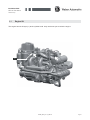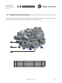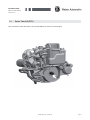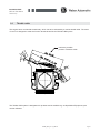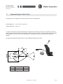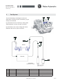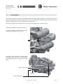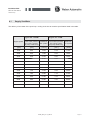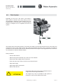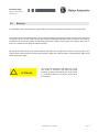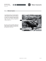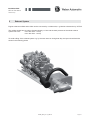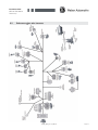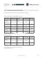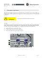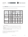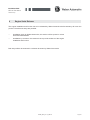
1
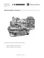
Installation Guide
MPE 750 Turbo Marine
Closed Loop
MPE 750 Turbo Marine - Closed Loop
This Installation Guide is valid for the following engine variants:
•
103666_I2 749 MAR TC-100 DS V4 2007 3.1
•
103730_I2 749 MAR TC-143 DS V1 2007 3.1
103666_EHB_Rev1.0_080215
Installation Guide
MPE 750 Turbo Marine
Closed Loop
Table of contents
1
Mechanical Installation
1
1.1
Engine lift
2
1.2
Engine fixation and decoupling
3
1.3 Power Take Off (PTO) 4
1.4
Throttle cable
5
2 Alignment engine to drive train
6
3
Fuel system
7
4
Cooling water 10
4.1
Supply sea water
12
4.2
Flush system
13
4.3
Boat tow
14
5
Exhaust system
15
6
Electric
17
6.1
Engine monitoring
18
6.2
Schema engine wire harness
19
6.3
Schema boat harness
20
6.4
Required connectors for boat harness
21
7
First run and brake in of engine
22
8
Maintenance
24
9
Serial release
25
10
Specification for fuel, oil and coolant
26
11
Basic dimensions
27
12
Reference addresses
28
13
Appendix
29
103666_EHB_Rev1.0_080215
Installation Guide
MPE 750 Turbo Marine
Closed Loop
1
Mechanical Installation
The following section describes the handling of the engine during installation and the assembly into the boat.
In general a clearance of 50 mm between engine and boat hull is required.
Vent openings of an area of 9000 m² is needed to give the engine enough air to operate.
103666_EBH_Rev1.0_080215
Page 1
Installation Guide
MPE 750 Turbo Marine
Closed Loop
1.1
Engine lift
The engine has two lift eyes (1) at the cylinder head. Only use these eyes to raise the engine.
1
103666_EBH_Rev1.0_080215
Page 2
Installation Guide
MPE 750 Turbo Marine
Closed Loop
1.2
Engine fixation and decoupling
The engine mounts are specific for marine applications, a decoupling to the boat is necessary. The picture
shows the placement and proposed engine bearings (1) of the marine engine.
2
1
3
Pos.
Part No
Description
QTY
1
100527
engine mount
2
102535
engine bracket front
1
3
100119
engine bracket rear
1
D62 H30 M12
103666_EBH_Rev1.0_080215
4
Page 3
Installation Guide
MPE 750 Turbo Marine
Closed Loop
1.3
Power Take Off (PTO)
The connection to the drive train is by a thread M24x2 on the PTO of the engine
103666_EBH_Rev1.0_080215
Page 4
Installation Guide
MPE 750 Turbo Marine
Closed Loop
1.4
Throttle cable
The engine has a mechanical throttle body which has to be activated by a marine throttle cable. The travel
of 70 mm is designed to meet the function throttle levers like the Teleflex JBS system.
maximum possible
position of bowden cable
The Teleflex JBS system is designated for jet boats and is available e.g. at Allpa Marine Equipment, part
number CH2300
103666_EBH_Rev1.0_080215
Page 5
Installation Guide
MPE 750 Turbo Marine
Closed Loop
2
Alignment Engine to Drive Train
The alignment of the engine to the drive train has to be in following limits
Radial alignment:
max. 0.8 mm [ 0.03 inch ]
Angular alignment: max. 0.5°
To check and adjust the alignment between the engine and the Weber Automotive Jet Propulsion System a
Weber Automotive alignment tool was designed. This tool is using a laser to get the engine with drive system
set up properly. The use of this tool is described in the installation manual of the Weber Jet Propulsion
System.
To adjust the alingnment engine shims (1) are available at Weber Automotive
1
Part No
Description
Thickness
103708
engine shim
0,5 mm
103707
engine shim
1,0 mm
103666_EBH_Rev1.0_080215
Page 6
Installation Guide
MPE 750 Turbo Marine
Closed Loop
3
Fuel System
The fuel pump (1) has to deliver 120 liters per hour at a pressure of 4.5 bar. A possible
pump and filter configuration is shown in the following picture. To ensure a safe and
adequate fuel delivery a minimum inner diameter of 8 mm is required for fuel hoses and
fittings. This includes fittings on the gas tank including gas pick up in the tank.
from gastank
1) fuel pump
2) main filter
3) pre filter
3
to engine
2
1
Fuel filters (2) (3) have to be used to be avoid damages on the fuel pump and malfunction of the fuel
injectors:
Prefilter (3):
•
105 μm
•
e.g. Pierburg 4.000.30.80.0
Mainfilter (2):
•
15 μm, filtergrade 95%
•
e.g. Mann&Hummel WK512
103666_EBH_Rev1.0_080215
Page 7
Installation Guide
MPE 750 Turbo Marine
Closed Loop
3
Fuel System
b
The fuel rails fittings ars designed conform to
SAE J2044. The use of quick connectors (1) (2) is
strictly recommended.
a
(a) Fuel Feed Line from Fuel Pump: Fitting SAE
J2044 diameter 7,89 mm for quick connector
(b) Fuel Return Line to tank: Fitting SAE J2044
diameter 7,89 mm for quick connectors
1
2
3
fuelrail
fuel tank
4
fuel pump
120liter/hour at 4.5bar
Pos.
Order No
Description
Specification
1
104227
quick connector
7,89x90°
Weber
2
104228
quick connector
7,89x180°
Weber
3
103450
fuel filter, pressure side
Mann & Hummel WK512
4
103397
fuel filter, intake side
Pierburg 4.000.30.80.0
103666_EBH_Rev1.0_080215
Manufacturer
Page 8
Installation Guide
MPE 750 Turbo Marine
Closed Loop
3
Fuel System
The engine and the fuel components including recommended fuel
filters and stainless steel fuel quick connectors are conform to:
•
USCG: Boatbilder handbook Subpart J - Fuel Systems:
Title 33 CFR Sections 183.501-183.590
•
DIN EN ISO 10088 - Pemanently installed fuel systems and
fixed fuel tanks
Consult the specifications for gas tanks, fuel pump and fuel line
installation of USCG Boatbilders handbook and the Directive 94/25/EG
last amended by 2003/44/EG
103666_EBH_Rev1.0_080215
Page 9
Installation Guide
MPE 750 Turbo Marine
Closed Loop
4
Cooling Water
The engine itself has no water pump to feed the open loop of the cooling system. In a combination with a jet
pump the sea water for cooling is delivered by the jet pump propulsion system. By using different propulsion
systems a water pump has to be integrated into the drive train.
The tube for the sea water supply has to be mounted to the fitting at the charge air cooler
103666_I2 749 MAR TC-100 DS V4 2007 3.1
(1) Fitting at charge air cooler for sea water
supply. Inner diameter of tube: 19mm
1
The water / water cooler has a fitting to drain
the water out of the open loop. This drainage
can be implemented into the sea water supply
tube.
water / water cooler
drainage
tube from jetpump
103666_EBH_Rev1.0_080215
Page 10
Installation Guide
MPE 750 Turbo Marine
Closed Loop
4
Cooling Water
103730_I2 749 MAR TC-143 DS V1 2007 3.1
(2) Fitting at charge air cooler for sea water
supply . Inner diameter of tube: 19mm
2
The water / water cooler has a fitting to drain
the water out of the open loop. This drainage
can be implemented into the sea water supply
tube.
water / water cooler
drainage
tube from jetpump
103666_EBH_Rev1.0_080215
Page 11
Installation Guide
MPE 750 Turbo Marine
Closed Loop
4.1
Supply Sea Water
The delivery of sea water of the open loop cooling circuit has to meet the specification listed in the table.
Engine: 98 - 105 kW
Engine: 49 - 76 kW
engine speed Fresh water pressure Waterflow Fresh water pressure Waterflow
HO cooling system HO system SO cooling system SO system
(at pump outlet Line)
(at pump outlet Line)
[ rpm]
[ bar ]
[ l/min ]
[ bar ]
[ l/min ]
1500
0.25
13.40
0.18
11.00
2000
0.26
17.50
0.22
12.20
2500
0.38
21.40
0.20
13.00
3000
0.58
26.20
0.25
15.00
3500
0.77
32.00
0.35
19.00
4000
0.98
36.70
0.51
24.00
4500
1.22
40.70
0.69
29.50
5000
1.49
47.20
0.92
35.00
5500
1.85
54.60
1.19
41.00
6000
2.20
61.60
1.53
46.50
6500
2.62
67.80
1.84
53.00
7000
3.00
71.70
2.20
59.00
7500
3.39
74.00
2.51
63.50
103666_EBH_Rev1.0_080215
Page 12
Installation Guide
MPE 750 Turbo Marine
Closed Loop
4.2
Flush System
Especially for the use of the boat in salt water a
flush system to rinse the open loop cooling circuit is
recommended. Therefore a flush system has to be
implemented by the boat builder. The following picture
shows an example how to implement this kind of
system.
Jetpump
The engine has a wet exhaust system. This means sea water is injected into the exhaust out of the open loop
cooling circuit. Due to this water injection the exhaust temperature and also noise is reduced. This water is
pressed out of the exhaust system by the exhaust pressure of the engine. If the engine does not run there is
no mechanism to drain the exhaust system.
Flush procedure:
• Connect the Flush kit
• Start the engine and operate only in idle. Do not accelerate
• Ensure the water supply within 30 seconds
• Flush the open loop cooling circuit for one minute minimum
• Stop water supply
• Stop engine within 30 seconds
• Remove the flush kit
Never flush without a running engine otherwise there is
a high risk to fill the engine with water
ATTENTION
The engine may only be operated at idle speed for
maximum of 30 seconds without flush water
103666_EBH_Rev1.0_080215
Page 13
Installation Guide
MPE 750 Turbo Marine
Closed Loop
4.3
Boat tow
In combination with a jet propulsion system there is a risk to fill the engine with water by towing the boat.
The engine has a wet exhaust system. This means sea water is injected into the exhaust out of the open loop
cooling circuit. Due to this water injection the exhaust temperature and also noise is reduced. This water is
pressed out of the exhaust system by the exhaust pressure / stream of the engine. If the engine does not run
there is no mechanism to drain the exhaust system.
By towing the boat the jet pump system delivers sea water to the engine even without running engine. This
means water will be injected into the exhaust system. When the exhaust system is fully filled with water it will
fill the engine with water.
ATTENTION
Don’t tow the boat with a high speed. If a high
tow speed is necessary the water feed tube
between jet pump and engine has to be closed
by a clamping device or a closure valve has to
be installed.
103666_EBH_Rev1.0_080215
Page 14
Installation Guide
MPE 750 Turbo Marine
Closed Loop
5
Exhaust System
The exhaust system of the spark ignition
marine engine is water cooled. A part of
the sea water is injected into the manifold
to reduce the exhaust temperature and
the noise in the system. This injected
water will leave the boat through the
exhaust system (1).
1
The rest of the sea water leaves the
engine through a fitting (2) at the bottom
of the exhaust manifold. This water has to
be drained out of the boat.
2
103666_EBH_Rev1.0_080215
Page 15
Installation Guide
MPE 750 Turbo Marine
Closed Loop
5
Exhaust System
Engine exhaust manifold and muffler can be connected by a rubber tube, e.g. Marine exhaust tube by VETUS.
The muffler should have a volume of approximately 17 Liter and the back pressure of the whole exhaust
system has to be:
max. 200 mbar - 143 hp
max. 180 mbar - 104 hp
To avoid a filling of the exhaust system e.g. by the stern wave or during boat slip, the layout should look like
shown in the following picture
103666_EBH_Rev1.0_080215
Page 16
Installation Guide
MPE 750 Turbo Marine
Closed Loop
6
Electric
The engine will be delivered including an engine wire harness and Engine ECU. All necessary connectors for
the vehicle wire hardness are listed in section 6.4. Also diameters of the wires in the vehicle harness have to
match the diameters of the engine harness.
103666_EBH_Rev1.0_080215
Page 17
Installation Guide
MPE 750 Turbo Marine
Closed Loop
6.1
Electric
The engine can give out following output / informations:
•
MIL (Malfunktion Indicator Light): Will be activated when engine performance is limited
•
Engine overtemperature lamp: Is activated when engine temperature exceed the limit
•
Oil pressure lamp
•
Engine speed signal
•
Engine up to 98 kW: 2 pulses/rev
•
Engine 105 kW: 6 pulses/rev
The wireing for the oil pressure lamp is not included in the engine wire
harness and has to be implemented in the boat harness.
The EMS / engine package includes sensors and control strategies for:
•
Raw water supply: temperature sensor in exhaust manifold
•
Altitude: air pressure sensor
•
Temperature: air and coolant temperature
•
RPM: Crank sensor
•
Start: Phase sensor for cylinder 1 detection
•
Turbo System: pressure sensor for boost control
•
Oil System: oil pressure switch to warning lamp
•
Emissions / Performance: closed loop lamda control
Specification
Malfunktion Indicator Light (MIL)
max. 10 Watt
engine overtemperature lamp
max. 10 Watt
oil pressure lamp
max. 10 Watt
engine speed signal
Engine up to 98 kW: 2 pulses/rev
Engine 105 kW: 6 pulses/rev
battery capacity
12 V / 10 Ah
starter solenoid
600 A steady state
internal generator with regulator
Idle: 150 Watt > 3000rpm: Watt max. 340 Watt
103666_EBH_Rev1.0_080215
Page 18
Installation Guide
MPE 750 Turbo Marine
Closed Loop
6.2
Schema engine wire harness
103666_EBH_Rev1.0_080215
Page 19
Installation Guide
MPE 750 Turbo Marine
Closed Loop
6.3
Schema boat wire harness
103666_EBH_Rev1.0_080215
Page 20
Installation Guide
MPE 750 Turbo Marine
Closed Loop
6.4
Required connectors for boat harness
Following table shows the connector parts needed fort he boat wire harness:
Connector to the engine wire harness (Engine / Chassis 1):
Description
Manufacturer Series
Part Number
Quantity
Connector
Housing 10
Delphi / Packard
Metri Pack 150
12065425
1
Delphi / Packard
Metri Pack 150
12124264
1
Female Terminals
Delphi / Packard
Metri Pack 150
12048074
8
cable seals
Delphi / Packard
Metri Pack 150
12048087
8
cavity plug
Delphi / Packard
Metri Pack 150
12059168
2
Part Number
Quantity
Cavities Female
Terminal Position
Assurance 10
Connector starter relay:
Description
Connector
Assembly 2F
Female Terminals
Manufacturer Series
Delphi / Packard
Metri Pack 150
12162195
1
Delphi / Packard
Metri Pack 150
12124075
2
All components for the connectors can be purchased at:
www. powerandsignal.com
103666_EBH_Rev1.0_080215
Page 21
Installation Guide
MPE 750 Turbo Marine
Closed Loop
7
First engine run and brake in
After the engine installation is finished a first run with the boat out of the water is recommended. Therefor use
the flush system to avoid any damage of the engine due to overheat. The use of the flush system is described
in section 4.2.
Engine is delivered filled with engine oil by the factory
ATTENTION
Procedure:
Check at first the connection to the drive train. Therefore disconnect the ignition coils to avoid a starting of the
engine. Crank the engine by using the starter, do not crank longer than 10 seconds and repeat as needed.
Check the drive train for abnormal behaviour (e.g. mechanical noise). Reconnect the ignition coils
1)
Remove cable harness on the ignition coils (1).
2)
Loosen the cable harness on the cable holders (2).
3)
Remove the cable harness on the injection valves (3).
1
2
3
103666_EBH_Rev1.0_080215
Page 22
Installation Guide
MPE 750 Turbo Marine
Closed Loop
7
First engine run and brake in
•
Prime the fuel system: Activate the fuel pump by turning on the key switch (not in start position).
•
Connect the flush system as described in section 4.2
•
Start engine. Do not accelerate. The engine may only be operated at idle speed for a maximum of 30
seconds without sea water
•
Ensure the water supply within 30 seconds
•
Check if the water out of the outer cooling loop is leaving the boat.
•
Check if the injected water is leaving the exhaust
•
Stop water supply
•
Check oil level as described on the hang tang on the oil tank
•
Check coolant level (1) of the inner cooling loop
1
Coolant level below the MIN marking can cause damage
to the engine due to overheating.
ATTENTION
Coolant level below the MAX marking should be avoided
to prevent environmental damage
103666_EBH_Rev1.0_080215
Page 23
Installation Guide
MPE 750 Turbo Marine
Closed Loop
8
Maintenance
every 50
■ 2)
after 25
Motor oil and oil
filter
Change
14
■ 2)
Coolant
Change
20
Check /
clean
23
Change
23
Valve play
Check /
set
26
Fuel filter
Change
32
Activity
see page
Maintenance interval
h 1)
Procedure
1st
maintenance
h 1)
Spark plugs
every 100
At end of season
Following table shows the maintenance intervals for the marine engine.
■
■ every 4 years 4)
■
■ 3)
■ 3)
■ 3)
■ 3)
1)
h = hours of operation
2)
or at least once a year if the hours of operation specified above are not reached before
that.
3)
or at least every two years if the hours of operation specified above are not reached
before that.
4)
Valid for engine manufacturer’s fill. Please note the instructions provided by coolant
manufacturer, when using other coolants.
For detailed maintenance informations please consult the service handbook.
This handbook can be downloaded in the service section at:
www.weber-motor.com
103666_EBH_Rev1.0_080215
Page 24
Installation Guide
MPE 750 Turbo Marine
Closed Loop
9
Engine Serial Release
The engine installation and function has to be released by Weber Automotive before warranty will cover the
product. Therefore two ways are possible:
•
Installation check by Weber Automotive, this service will be quoted on a time
travel and mateial basis
•
Installation by customer: the customer has to provide evidence of the engine
installation and function
Both ways will be documented in a release document by Weber Automotive.
103666_EBH_Rev1.0_080215
Page 25
Installation Guide
MPE 750 Turbo Marine
Closed Loop
10
Specification for fuel, oil and coolant
Fuel:
Fuel quality
Unleaded gasoline according to DIN 51607 („super
unleaded“), with an octane rating of at least 95 ROZ
[RON] or 85 MOZ [MON]
Oil:
Recommendiation:
15W 50 completely synthetic, API SH, JASO MA
Alternative
0W 50
Fill quantity
Initial filling 4.2 liters [4.4 qt (US)]
Oil change with filter 3.3 - 3.5 liters
[3.5 - 3.7 qt (US)]
Coolant:
Coolant additive:
Coolant additive based on ethylene glycolsilicate and
nitrite-free. Suitable for aluminium engines.
Anti-freeze mixture
50% water + 50% coolant additive
Fill quantity
3.3 liters [3.5 qt (US)]
Approved coolant additives
BASF Glysantin G30
Chevron Havoline Extended Life Coolant XTC+B
Valvoline Zerex G30
Manufacturer´s fill provides frost protection up to -37°C [-34.6°F]
Recommended minimum frost protection up to -30°C [-22°F]
103666_EBH_Rev1.0_080215
Page 26
Installation Guide
MPE 750 Turbo Marine
Closed Loop
11
Basic dimensions [mm]
117,5
424
547
Please contact Weber Automotive for detailed drawings or CAD models.
214
332
52,5
720
609
140°
140°
295
400
103666_EBH_Rev1.0_080215
Page 27
Installation Guide
MPE 750 Turbo Marine
Closed Loop
12
Reference Adresses
Throttle cable:
RCS: Remote Control Systems GmbH
www.r-c-s-online.de
Contact Mr. Frank Schneider
[email protected]
Helm Throttle Level:
Teleflex
www.teleflexmorse.com
Allpa Marine Equipment
www.allpa.nl
www.allpa.de
www.allpa.eu
Exhaust Tube:
Vetus
Allpa Marine Equipment
www.allpa.nl
www.allpa.de
www.allpa.eu
Engine Monitoring:
VDO Marine
www.vdo-marine.com
Contact Mr. Joachim Smolka
[email protected]
Connector:
Power&Signal Group
www.powerandsignal.com
103666_EBH_Rev1.0_080215
Page 28
Installation Guide
MPE 750 Turbo Marine
Closed Loop
103666_EBH_Rev1.0_080215
Page 29