1
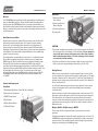
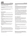
TEAM PRODUCTS INTERNATIONAL INC. Limited Warranty
What is covered: Any defect in materials and workmanship.
For how long: 2 years from date of purchase.
What we will do: If your product is defective and returned within 30 days
after the date it was purchased, we will replace it at no charge to you. If
returned after 30 days but within 2 years of the date of purchase we will
repair it or, at our option, replace it at no charge to you.
If we repair your product, we may use new or reconditioned replacement
parts. If we choose to replace your product, we may replace it with a
new or reconditioned one of the same or similar design. The repair or
replacement will be warranted under our standard 2 year warranty.
LIMITATIONS: Implied warranties, including those of fitness for a
particular purpose and merchantability (an unwritten warranty
that the product is fit for ordinary use), are limited to 2 years
from date of purchase. We will not pay for loss of time, inconvenience, loss of use of your product or property damage caused
by your product or its failure to work, or any other incidental
or consequential damages including personal injury.
Some states do not allow limitations on how long an implied warranty
lasts or the exclusion or limitation of incidental or consequential damages,
so the above exclusions or limitations may not apply to you.
What we ask you to do: To get warranty service for your product,
you must provide proof of the date of purchase. Within 30 days of the
date it was purchased, return your product to your place of purchase for
immediate replacement. After 30 days, but before the end of the 2 year
warranty period, you may return the product to the following address:
TEAM PRODUCTS INTERNATIONAL INC.
Attn: Customer Service Returns
35 A Continental Drive
Wayne, NJ 07470
We suggest that you retain your original packing material in the event
you need to ship your product. When sending your product include your
name, address, phone number, proof of date of purchase, and a
description of the operating problem. After repairing or replacing your
product, we will ship it to your home or office within four weeks.
What this warranty does not cover: Among other things this
warranty does not cover defects resulting from accidents,
damage while in transit to our service location, alterations,
unauthorized repair, failure to follow instructions, misuse, fire,
flood, and acts of God. If your product is not covered by our
warranty, call our Customer Service number at (888) 231-4022 to
determine whether we will repair your product and other repair
information, including charges. We, at our option, may replace
rather than repair your product with a new or reconditioned
one of the same or similar design. The repair or replacement will
be warranted for 2 years.
This limited warranty is the only one we give on your product,
and it sets forth all our responsibilities regarding your product.
There are no warranties which extend beyond the description set
forth above.
State Law Rights: This warranty gives you specific legal rights and you
may also have other rights which may vary from state to state.
PMP3000033106-82
3000 WATT
Power Inverter
Owner’s Manual
PMP3000 Models
©2006 The Coleman Company, Inc. All rights reserved.
COLEMAN® and
are registered trademarks of The Coleman Company, Inc., used under license. Designed in the USA and
custom-manufactured in China for Team Products International Inc. Distributed by Team Products International Inc., Mountain Lakes, NJ 07046.
Owner’s Manual
PMP3000 Models
Rear Panel
Welcome
This COLEMAN® product has been carefully engineered and manufactured to
give you dependable operation. Please read this manual thoroughly before
operating your new COLEMAN® product, as it contains the information you
need to become familiar with its features and obtain the performance that will
bring you continued enjoyment for many years. Please keep this manual on file
for future reference.
10
7. Power Input Terminal
Red = Positive
8. Power Input Terminal
Black = Negative
9. Ground Lug Terminal
10. Cooling Fan
How Power Inverters Work
Power inverters convert low voltage DC (direct current) power to 120 volt AC
(alternating current) household power. This conversion process thereby
allows you to use household products, power tools, and other electronic
products away from normal AC power sources (standard 120V wall outlets).
Depending on the model and its rated capacity, inverters can draw power either
from standard 12-volt automobile and marine batteries or from portable high
power 12-volt power sources.
The waveform that is generated by this conversion is a “modified sine wave”.
The modified sine wave produced by our inverters has a root square mean
(RMS) voltage of 120 volts, which is the same as standard household power.
The majority of AC voltmeters are calibrated for RMS voltage under the
assumption that the measured waveform will be a pure sine wave. Therefore,
these meters will not read the RMS modified sine wave voltage correctly. They
will read about 20 to 30 volts too low. To accurately measure the output
voltage of the inverter, use a true RMS reading voltmeter such as a Fluke 87,
Fluke 8060A, Beckman 4410, Triplett 4200 or any voltmeter identified as a
“true RMS”.
Controls and Components
9
8
CAUTION
• The inverter is designed to operate from a 12-volt power source only. The unit
will not operate from a 6-volt battery or a 24-volt battery. Do not attempt to
connect the inverter to any other power source other than a battery
with a nominal output voltage of 12 volts or damage to the unit may
occur and will void the warranty.
• 120 volts can inflict serious injury, damage or death. Improper use of the inverter may result in property damage, personal injury or loss of life.
Getting Started
When you turn on an appliance or tool that operates using a motor or a tube
(such as a television), it requires an initial surge of power to start up. This surge
of power is referred to as the “starting load” or “peak load”. Once started, the
appliance or tool requires less power to continue to operate. This is referred to
as the “continuous load”.
You will need to determine how much power your appliance or tool requires
to start up (peak power) and it’s continued operating power requirements
(continuous load).
Front Panel
1. LED Indicator Light (Green = Power ON, Red = Overload)
2. Remote Control Connection
7
5. Display Selector Switch
Power consumption is rated in either wattage (watts) or amperes (amps). This
information is usually stamped or printed on most appliances and equipment.
If this information is not indicated on the actual product, check the owner’s
manual or contact the manufacturer to determine the power consumption. Be
sure that the power consumption of the item you wish to operate is rated at
3000 watts or less.
6. 120 Volt AC Outlets
Multiply: AMPS x 120 (AC voltage) = WATTS
4
3. ON/OFF Power Switch
5
4. Digial Display
This formula yields a close approximation of the continuous load of the
appliance.
3
2
1
1
6
To determine whether the inverter will operate a particular item, run a test. All
COLEMAN® inverters are designed to automatically shut down in the event of
a power overload. This protection feature prevents damage to the unit while
testing items with ratings in the 3000-watt range.
2
Owner’s Manual
PMP3000 Models
Connecting the Inverter
Notes
When connecting the inverter to the power source, it is recommended to use
the thickest wire available in the shortest length possible. If the inverter and the
battery are positioned within 4 feet of each other, a minimum of #0 gauge wire
should be used to make the connections. When the distance between them is
4 to 6 feet, a minimum of #00 gauge wire is required. When separated by more
than six feet, contact a qualified technician to determine the appropriate wire
size to use given the distance between the inverter and the battery.
• Loose connections can result in a severe decrease in voltage, which may cause
damage to the component or the product you wish to operate.
1. Make sure the ON/OFF power switch located on the front panel of the inverter
is in the OFF(O) position.
2. Loosen and remove the bolts and nuts from the red (+) and black (-) power
input terminals.
3. It is recommended to use a crimped “loop style” connector on the ends of the
cables when connecting the cables to the inverter.
4. Connect the cable wires to the power input terminals making sure to match
the color coded cables to the color coded terminals on the inverter (RED=
Positive, BLACK = Negative). Tighten the bolts and nuts to secure the cables.
Be sure not to over tighten. Note: A secure connection is essential to proper
operation of the inverter. Be certain to use the supplied bolts, nuts and washers included to connect the cables.
5. Connect the cable from the Positive (+) terminal (RED) on the inverter to the
Positive terminal on the power source. Double check that the connection is
secure.
6. Locate the Ground Lug Terminal at the rear of the inverter. Run a wire from
this terminal to a proper grounding point using the shortest practical length.
It is recommended to use a minimum of 12 AWG wire. You can connect
this wire to the chassis of your vehicle or to the grounding system in your
boat. As an alternative, when in remote locations the ground wire can be
connected to the earth (one way to accomplish this is to attach the wire to a
metal rod driven into the ground). Before connecting to the ground, make
certain that the inverter is turned off. Operation the inverter without correctly
grounding the unit may result in electrical shock.
7. Turn the inverter power switch to the ON(I) position. The LED Indicator Light
should illuminate GREEN to confirm that power is running to the inverter.
8. Turn the inverter power switch to the OFF(O) position. (The LED Indicator
Light may “blink” briefly and/or the internal audible alarm may make a momentary “chirp”. This is normal).
• Failure to make a proper connection between the inverter and the power
source may result in reverse polarity. Reverse polarity will blow the internal
fuses in the inverter and may cause permanent damage to the inverter.
Damage caused by reverse polarity is not covered under the warranty.
• The audible alarm may make a momentary “chirp” when the inverter is turned
ON(I) or OFF(O). This same alarm may also sound when the inverter is being
connected to or disconnected from the 12-volt power source. This is normal.
• If the LED Indicator Light blinks when you first turn the inverter ON(I), this may
indicate an interruption of the power supply. Simply turn the inverter OFF(O)
and try removing and reconnecting the clamps. If this does not fix the
problem, try using a different 12-volt power source.
• If using more than one appliance, do not exceed a combined total of
3000 watts.
Source of Power
Most automobile, truck and marine batteries will provide an ample power
supply to the inverter for 30 to 60 minutes even when the engine is turned off.
Actual time may vary depending on the age and condition of the battery and the
power demand being placed on it by the equipment being operated.
If you decide to use the inverter while the engine is off, we recommend that you
start the engine every 30 to 60 minutes and let it run for approximately 10
minutes to recharge the battery. It is also recommended that the device
plugged into the inverter be turned OFF before starting the vehicle engine.
Although it is not necessary to disconnect the inverter when starting the vehicle
engine, it may momentarily cease to operate as the battery voltage decreases.
When the inverter is not supplying power, it draws very low amperage from the
battery. It is recommend that the inverter always be disconnected when not in
use.
Note: Always disconnect the power inverter from the 12-volt power source and
make sure the inverter is turned OFF before replacing the fuse.
Safety and Usage Precautions
9. Make sure that the device you intend to operate is turned OFF. Plug the cord
from the equipment you wish to operate into one of the AC outlets located on
the front panel of the inverter.
• For best operating results, place the inverter on a flat surface
10. Turn the inverter power switch to the ON(I) position. Then turn the
equipment on.
• DO NOT operate the inverter if you, the inverter, the device being operated, or
any surface that may come into contact with the inverter are wet. Water and
other liquids can conduct electricity, which may lead to serious injury
or death.
3
• Keep inverter dry. Do not expose inverter to rain or moisture.
4
Owner’s Manual
PMP3000 Models
• Avoid placing the inverter on or near heating vents, radiators or other
sources of heat. Do not place or use the inverter in direct sunlight. Ideal air
temperatures should be between 50° and 80° F.
• In order to properly disperse the heat generated from the inverter while it is
operating, keep the inverter well ventilated. Keep the area surrounding the
inverter clear while in use.
• Do not use the inverter near flammable materials. Do not place the inverter in
areas such as battery compartments where fumes or gases may
accumulate.
Inverter Protection Features
• Short Circuit Protection. The inverter will automatically shut down until
short is removed.
• Low Voltage Alarm. An alarm will sound when the voltage from the battery
discharges to 10.5 +/- 0.5 volts DC. This is an indication that the battery needs
to be recharged.
• Over Voltage Protection. The RED LED Indicator Light will illuminate and
the inverter will automatically turn itself off when the input exceeds 16.5 +/- 1
volt DC.
• Under Voltage Protection. The RED LED Indicator Light will illuminate and
the inverter will automatically turn itself off when the input is less than 10.0
+/- 0.5 volts DC.
• Overload Protection. The RED LED Indicator Light will illuminate and the
inverter will automatically turn itself off when the continuous draw of the
equipment being operated exceeds 3000 watts or the surge draw of the
equipment exceeds 6000 watts.
• Thermal Protection. The RED LED Indicator Light will illuminate and the
inverter will automatically turn itself off when the circuit temperature
exceeds 150° F.
Notes
• The inverter is equipped with a cooling fan, which is designed to turn on
when the unit gets hot. When the temperature inside the inverter exceeds the
limits of safe operation, the cooling fan will automatically turn on to cool the
inverter. When the temperature has lowered to a safe operating degree, it will
shut off.
• In the event of automatic shut down or a continuous audible alarm, turn the
inverter power switch to the OFF(O) position until the source of the problem
has been determined and resolved.
5
Digital Display
When the selector switch is in the “watt” position, the display will indicate the
total wattage being produced by the inverter. This will vary depending on the
appliance being operated by the inverter. If the reading is over 3000 watts, the
inverter will automatically shut down. This most often happens when the
current draw of the appliance being operated is greater than the inverter is
capable of producing.
When the selector switch is in the “volt” position, the display will indicate the
input “voltage” from the battery. The inverter will operate with input voltage
ranging from 11 to 15 volts of direct current (DC). If the voltage level falls below
10.5 +/- 0.5 volts DC, an audible alarm will sound. Should the voltage drop
below 10 +/- 0.5 volts DC, the inverter will automatically shut down. The
inverter may be damaged if the input voltage exceeds 15 volts, and the inverter
will automatically shut down. However, despite this safety feature, excessive
voltage may cause damage to the inverter. Damage caused by excess voltage
input is not covered under the warranty.
Television and Audio Suggestions
Although all COLEMAN® inverters are shielded and filtered to minimize
signal interference, some interference with your television picture may be
unavoidable, especially with weak signals. However, here are some
suggestions that may improve reception:
• Make sure the television antenna produces a clear signal under normal
operating conditions (at home plugged into a standard 120 volt AC outlet).
Also, ensure that the antenna cable is properly shielded and/or good quality.
• Change the positions of the inverter, antenna cables and the television power
cord.
• Isolate the television, its power cord and antenna cables from the 12-volt
power source by running an extension cord from the inverter to the
television set.
• Coil the television power cord and the input cables running from the 12-volt
power source to the inverter.
• Attach an AC interference filter or similar product between the inverter and the
television power cord. These filters are available at most electronic supply
stores, including Radio Shack.
Note: Inexpensive sound systems may emit a “buzzing” sound when
operated with an inverter. This is due to the inadequate filters in the sound
system. There is no solution to this problem other than purchasing a sound
system with a higher quality power supply.
6
Owner’s Manual
PMP3000 Models
Troubleshooting
In Review
PROBLEM: Low or No Output Voltage
• Never attempt to operate the inverter from any other power source other than
a 12-volt battery.
• When connecting and using the inverter, make sure that the inverter is
positioned far away from any potential source of flammable fumes or gases.
• Make certain that the power consumption of the equipment you wish to
operate is compatible with the capacity of the inverter. Do not exceed
3000 watts in total power, or 1600 watts for each individual AC outlet.
• When attempting to operate battery chargers, monitor the temperature of the
battery charger for approximately 10 minutes. If the battery charger
becomes abnormally warm, disconnect it from the inverter immediately.
• Use only 30 amp spade type fuses for the inverter.
• When operating the inverter with an automobile or marine battery, start the
engine every 30 to 60 minutes and let it run for approximately 10 minutes to
recharge the battery.
Reason
Solution
Poor contact with battery terminals.
Clean terminals
thoroughly. Reattach
battery clips.
Using incorrect type of voltmeter to test
output voltage.
Use true RMS reading meter.
PROBLEM: Red LED On
• In the event of a continuous audible alarm or an automatic shut down of the
unit, turn the inverter OFF immediately. Do not turn the inverter ON again
until the source of the problem has been identified and corrected.
Reason
Solution
• To avoid battery drain, always disconnect the inverter when not in use.
Battery voltage below
10.0 ± 0.5 volts.
Recharge or replace battery.
Equipment being operated draws too much power.
Use a higher capacity inverter
or do not use this equipment.
Inverter is too hot (thermal shutdown mode).
Allow inverter to cool.
Check for adequate ventilation.
Reduce the load on the
inverter to rated continuous
power output
Unit may be defective.
See Warranty and call Customer service at
1-888-231-4022.
• Do not expose the inverter to rain or moisture.
• Avoid placing the inverter near sources of heat or in direct sunlight.
• While in use, make sure that the inverter is properly ventilated.
• For best operating results, make sure the unit is placed on a flat surface.
7
8
Owner’s Manual
PMP3000 Models
Troubleshooting
PROBLEM: TV Interference
Specifications:
Reason
Solution
Electrical interference from
the inverter.
Add an AC interference filter on to the TV power cord. Refer
to TV and audio section of
this manual.
PROBLEM: Low Battery Alarm On All The Time
Reason
Solution
Input voltage below 10.5 ± 0.5 volts.
Keep input voltage above 10.5±0.5
volts to maintain regulation.
Poor or weak battery condition.
Recharge or
replace battery.
Inadequate power being delivered to the inverter
or excessive voltage drop.
Make sure connection is secure.
Use lower gauge wire. Keep
wire length as short as possible.
Maximum Continuous Power
3000 Watts
Surge Capacity (Peak Power)
6000 Watts
Max Power Efficiency
>80%
Waveform
Modified Sine Wave
No Load Current Draw
<2A
Input Voltage Range
11-15VDC
AC Receptacles
120V AC, Grounded
Fuse
15 x 30 amp (spade type)
Weight
18.5 lbs.
Dimensions
19.9” (L) x 9.055”(W) x 6.14” (H)
505mm(L) x 230mm(W) x 156mm(H)
Questions?
If you have any questions about this product, please contact our Customer
Service Department at (888) 231-4022, Monday through Friday, 9 AM to 5 PM
EST, or visit our website at www.colemanpower.com.
PROBLEM: TV Does Not Work
Reason
Solution
TV does not turn on.
Try turning the inverter
ON/OFF/ON.
Contact TV manufacturer for
start up surge and power
consumption.
A larger inverter may
be required.
9
10