1
BJC-4300
SERVICE
MANUAL
Canon
Application
This manual has been issued by Canon Inc. for qualified persons to learn technical theory,
installation, maintenance, and repair of products. This manual covers all localities where the
Droducts are sold. For this reason, there may be information in this manual that does not apply to
;oIlr locality.
Corrections
This manual could include technical inaccuracies or typographical errors due to improvements or
changes in the products. When changes occur in applicable products or in the content of this
manual. Canon will release technical information as the need arises. In the event of major changes
in the contents of this manual over a long or short period, Canon will issue a new editions of this
manual.
The following paragraph does not apply to any countries where such providons are
inconsistent with local law.
Trademarks
The product names and company names described in this manual are the registered trademarks of
the individual companies.
Copyright
This manual is copyrighted with all rights reserved. Under the copyright laws, this manual may not
be copied, reproduced or translated into another language. in whole or in part, without the written
consent of Canon Inc., except in the case of internal business use.
Copyright 0 1997 by Canon inc.
CANON INC.
BJ Products Technical Support Dept
16-1, Shimonoge 3-chome, Takatsu-ku, Kawasaki-shi, Kanagawa 213, Japan
This manual was produced on an Apple MacintoshTU Power Mac 6500/180 personal computer and
Apple LaserWriterTM16/600PS-J laser beam printer: final pages were printed on VarityperTu 5300
with 4OOOJ RIP. All graphics were produced with MACROMEDIA@ FREEHANDa 5.55.
All documents and all page layouts were created with QuarkXPressT” 3.35.
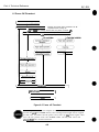
This manual is divided into four sections, and contains information required for
servicing the unit.
Part 7: Safety and Precautions
This section tells you how to service the unit safely.
read it.
It is very important, so please
Part 2: Product Specifications
This section outlines and specification.
Part 3: Operating Instructions
This section explains how to operate the unit properly.
installation and service made.
Information required about
Part 4: Technical Reference
This section outlines the way the unit operates so you can understand it technically.
Part 5: Maintenance
This section explains how to maintain the unit. Descriptions of assembly/disassembly,
adjustment for assembly, troubleshooting procedures, and wiring/circuit diagrams
are given.
Procedures for assembly/disassembly are not given in this manual.
See the illustrations in the separate Parts Catalog.
I
Part 1: Safety and Precautions
Page
l- 1
l- 1
1-2
1-2
1-3
1-4
1-5
1-5
1-5
l - 5
l - 6
1-6
1-6
l - 7
l - 7
l - 7
l - 6
l - 6
l - 6
l - 9
1-9
l-10
l-10
l-10
1 -11
1 -11
l-12
l-13
1-13
1. SAFETY PRECAUTIONS
1 .I Moving Parts
1.2 Ink Stains
1.2.1 Ink path
1.2.2 Ink mist
1.3 BJ Cartridge Heat-Up
2. MACHINE PRECAUTIONS
2.1 Handling BJ Cartridges
2.1 .l Unpacking the BJ cartridge
2.1.2 Preventing clogged nozzles
2.1.3 Power on/off
2.1.4 When not using the printer
2.1.5 Ink electroconductivity
2.2 Handling Ink Cartridges
2.2.1 Unpacking the ink cartridge
2.2.2 Preventing clogging
2.3 Printer Precautions
2.3.1 Spur deformation prevention
2.3.2 Static electricity damage prevention
2.3.3 Ink leakage prevention
2.3.4 Waste ink adhesion prevention
2.4 Scanner Precautions
2.4.1 Scanner Cartridge Protection
2.4.2 Scanning Precautions
3. PRECAUTIONS FOR SERVICE
3.1 EEPROM Data Precautions
3.2 Static Electricity Precautions
3.3 Disassembly and Reassembly Precautions
3.4 Self-Diagnosis
2- 1
2- 1
2- 2
2- 3
2- 3
2- 3
2- 4
2- 4
2- 4
2- 5
2- 5
2- 5
2- 6
2- 6
2- 7
2- 7
2-a
2- 8
2 -11
1. PRODUCT OUTLINE
1.1 Product Outline
1.2 Features
1.3 BJ Cartridge
1.3.1 Color BJ cartridge (Multi drop)
1.3.2 Black BJ cartridge
1.3.3 Photo BJ cartridge (Multi drop)
1.4 BJ Cartridge Container
1.5 AC Adapter
1.6 Consumables
1.6.1 BJ cartridges (Color, Black, Photo)
1.6.2 Ink cartridge (Color BJ cartridge)
1.7 Option
1.7.1 Color image scanner cartridge
1.7.2 Scanning holder
1.7.3 White calibration sheet
2. SPECIFICATIONS
2.1 Printer Specifications
2.2 Scanner Cartridge Specifications (Option)
Part 2: Product Specifications
II
2
2
2
2
2
2
-12
-13
-14
-21
-21
-24
2.3 Paper Specifications
2.3.1 Paper size
2.3.2 Paper type (Recommended)
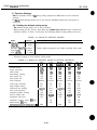
2.3.3 Print paper
2.3.4 Printing range
2.4 Interface Specifications
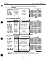
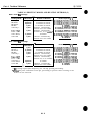
2.5 Character Code Tables
2.5.1 BJ mode
2.5.2 EPSON mode
Part 3: Operating instructions
a
0
333333-
1
1
2
3
3
3
3- 3- 4 4
3- 7
3- 6
3- 9
3- 9
3- 9
3 -10
3 -10
3 -11
3 -13
3 -13
3 -13
3 -14
3 -14
3 -16
3 -16
3 -17
3 -20
3 -21
3 -21
3 -22
3 -23
3 -23
3 -24
3 -25
3 -25
3 -26
I. PRINTER SETUP
1 .I Equipment Check
1.2 Printer Dimensions
1.3 Setup Procedure
1.3.1 Connecting the interface cable
1.3.2 Connecting the AC adapter
1.3.3 Turning on the printer
1.3.4 Installing the cartridge
1.3.5 Replacing the ink cartridge
1.3.6 BJ cartridge container
1.4 Turning the Printer On/Off
1.4.1 Turning the printer on
1.4.2 Turning the printer off
1.5 Paper Settings
1.6 Banner Print
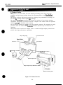
1.7 Name of the Parts and Their Functions
2. TRANSPORTING THE PRINTER
2.1 Carrying the Printer
2.2 Transporting the Printer
3. PRINTER SERVICING FUNCTIONS
3.1 Error Indications
3.2 Function Settings
3.2.1 Setting the default setting mode
3.2.2 BJ setup utility program
3.3 Cleaning the BJ Cartridge
3.4 Self-Test Printout
3.4.1 Demonstration print
3.4.2 Printer status information print
3.4.3 ASCII character print (ripple pattern)
3.4.4 Nozzle check pattern
3.5 Hexadecimal Dump Test Printout
3.6 EEPROM Reset
3.6.1 EEPROM Reset
3.6.2 Printing the EEPROM data
Part 4: Technical Reference
0
444444-
1
1
2
3
4
4
1. OVERVIEW
1 .I Printer Diagram
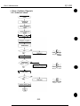
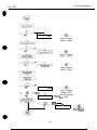
1.2 Initial Flowchart
1.3 Print Signal Flow
1.4 Print Drive
1.4.1 Printing drive control
Page
4- 6
4- 7
4- 7
4- 0
4- 9
4 -10
4 -11
4 -11
4 -11
4 -12
4 -12
4 -12
4 -12
4 -15
4 -1 5
4 -16
4 -16
4 -16
4-17
4 -17
4 -17
4 -19
4 -19
4 -20
4 -21
4 -22
4 -29
4 -29
4 -30
4 -31
4 -31
4 -32
4 -34
4 -34
4 -36
4-37
4 -37
438
4 -38
4 -39
442
442
4-42
4-42
4-42
4-43
443
444
444
4-44
445
447
448
448
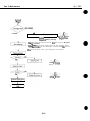
1.5 Power Off Flowchart
2. FIRMWARE
2.1 Interface
2.1 .I Compatible mode
2.1.2 Nibble mode
2.1.3 ECP mode
2.2 720 dpi Printing/Smoothing Feature
2.2.1 Canon extension mode
2.2.2 Emulation mode
2.3 Printing Modes
2.3.1 Printing mode
2.3.2 Photo print mode
2.3.3 Multi drop print mode
2.4 Optimum Printing Direction Control
2.5 Automatic Emulation Switching
2.6 Ink Smear Control
2.7 Head Overheating Protection Control
2.8 Auto Power On/Off
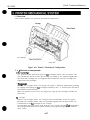
3. PRINTER MECHANICAL SYSTEM
3.1 Overview
3.1.1 Mechanical components
3.2 BJ Cartridge
3.2.1 Black BJ cartridge structure
3.2.2 Color BJ cartridge structure
3.2.3 Photo BJ cartridge structure
3.2.4 Bubble head unit structure
3.3 Purge Unit
3.3.1 Purge unit functions
3.3.2 Purge unit structure
3.4 Carriage
3.4.1 Carriage functions
3.4.2 Carriage structure
3.5 Paper Feed
3.5.1 Outline of the paper feed
3.5.2 Auto feed/Manual feed
4. PRINTER ELECTRICAL SYSTEM
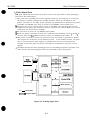
4.1 Overview
4.2 Logic Section
4.2.1 Logic section block diagram
4.2.2 Logic section components
5. SENSOR FUNCTIONS
5.1 Pick-up Roller Sensor
5.2 Paper End Sensor
5.3 Home Position Sensor (Purge Sensor)
5.4 Temperature Sensor
5.5 Head Temperature Sensor
5.6 Waste Ink Amount Detection
6. SCANNER CARTRIDGE
6.1 Scanner Cartridge Overview
6.1.1 Block diagram
6.2 Scanner Cartridge Structure
6.3 Signal Contacts
6.4 Scan Mode
6.5 Calibration
IV
Page
5- 1
5- 1
5- 1
5- 1
5- 2
5- 2
5- 3
5- 4
5- 4
5- 4
5- 4
5- 4
5- 5
5- 5
5- 5
5- 6
5- 6
5- 6
5- 6
5- 7
5- 7
5- 6
5 -10
5 -10
5 -10
5 -10
5 -12
5 -12
5 -15
5 -30
5 -30
5 -32
5 -32
5 -32
Part 5: Maintenance
1. MAINTENANCE
1.1 Parts for Regular Replacement
1.2 Consumables
1.3 Periodic Maintenance
2 SERVICING TOOLS
2.1 List of Tools
3. GREASE APPLICATION
4. DISASSEMBLY AND REASSEMBLY
4.1 Disassembly and Reassembly
4.2 Disassembly and Reassembly Cautions
4.2.1 Waste ink absorber installation
4.2.2 Carriage guide frame installation
4.3 Logic Board and Waste Ink Absorber Replacement CSUtiOnS
4.3.1 Logic board replacement cautions
4.3.2 Cautions afler replacing the waste ink absorber
5. ADJUSTMENTS
5.1 Adjustment Point
5.2 When Adjustment is Required
5.2.1 Tools required for adjustment
5.3 Adjustment Procedure
5.3.1 Preparation
5.3.2 Adjustment
6. TROUBLESHOOTING
6.1 Troubleshooting
6.1.1 Overview
6.1.2 Troubleshooting cautions
6.2 Error Condition Diagnosis
6.2.1 Initial self check
6.2.2 Error recovery
7. LOCATION & SIGNAL ASSIGNMENT
7.1 Logic Board
8. CIRCUIT DIAGRAMS
6.1 Parts Layout
6.1.1 Logic board
V
-
I
0
D
0
Page
I- 1
1-2
1-3
1-3
1-4
1-5
1-5
1-7
1-7
1-8
1-8
1-9
l-10
l-10
l-12
l-13
2- 1
2- 3
2- 3
2- 4
2- 4
2- 4
2- 5
2- 5
2- 6
2- 7
2 -13
2 -13
2 -19
2 -20
2 -20
3- 1
3- 2
3- 3
3- 3
3-4
3-4
3- 5
3- 7
3- 7
3- 6
3- 9
3 -10
3 -11
3 -12
3 -12
3 -13
3 -14
3 -17
3 -21
Figure
Figure
Figure
Figure
Figure
Figure
Figure
Figure
Figure
Figure
Figure
Figure
Figure
Figure
Figure
Figure
Figure
Figure
Figure
Figure
Figure
Figure
Figure
Figure
Figure
Figure
Figure
Figure
Figure
Figure
Figure
Figure
Figure
Figure
Figure
Figure
Figure
Figure
Figure
Figure
Figure
Figure
Figure
Figure
Figure
Figure
Figure
Figure
Figure
Figure
l- 1
I- 2
I- 3
I- 4
I- 5
l- 6
l- 7
l- 8
l- 9
l- 10
l- 11
I- 12
1-13
l- 14
l- 15
1-16
2- 1
2- 2
2- 3
2- 4
2- 5
2- 6
2- 7
2- 8
2- 9
2- 10
2- 11
2- 12
2- 13
2- 14
2- 15
3- 1
3- 2
3- 3
3- 4
3- 5
3- 6
3- 7
3- 8
3- 9
3- 10
3- 11
3- 12
3- 13
3- 14
3- 15
3- 16
3- 17
3- 18
3- 19
Moving Parts of the Printer
Ink Path
Ink Path of the BJ Cartridge
Ink Mist
BJ Cartridge Aluminum Plate
Removing the BJ Cartridge Protector
BJ Cartridge
Removing the Ink Cartridge Cap
Ink Cartridge Protection
Spurs and Spur Cleaner
Carriage Ribbon Cable’s Electrical Contacts
Capping Position
Scanner Cartridge
Scanning Holder
Electrical System of Printer
How to Release Plastic Hooks
Printer Exterior
Color BJ Cartridge (Multi Drop)
Black BJ Cartridge
Photo BJ Cartridge (Multi Drop)
BJ Cartridge Container
AC Adapter
BJ Cartridges
Ink Cartridges
Scanner Cartridge
Scanning Holder
Printing Area
Printing Area (Envelope)
Timing Chart (Compatible Mode)
Timing Chart (Nibble Mode)
Timing Chart (ECP Mode)
Packaging
Printer Dimension
Connecting the Interface Cable
Connecting the DC Power Cord
Removing the BJ Cartridge Protectors
BJ Cartridge Handling Precautions
Cartridge Installation
Removing the Ink Cartridge
Removing the Ink Cartridge Cap
BJ Cartridge Container
Do not turn off the printer without pressing the POWER button first
Banner Print
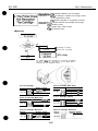
Name of the Parts and Their Functions
Name of the Parts and Their Functions
Paper Thickness Lever
Fastening the Carriage
Control Panel
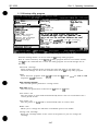
BJ Setup Utility Program (Sample)
Demonstration Print (Sample)
VI
0
-
0
Page
3 -22
3 -23
3 -23
3 -24
3 -26
4- 1
4- 2
4- 3
4- 4
4- 5
4- 6
4- 8
4- 9
4 -10
4 -11
4 -17
4 -19
4 -20
4 -21
4 -22
4 -23
4 -23
4 -25
4 -25
4 -26
4 -30
4 -31
4 -32
4 -33
4 -34
4 -36
4 -37
4 -38
4 -38
441
442
4 -44
4 -44
4 -45
447
5- 3
5- 4
5- 4
5- 5
5- 6
5- 7
5- 8
5- 9
5 -30
5 -32
5 -33
Figure
Figure
Figure
Figure
Figure
Figure
Figure
Figure
Figure
Figure
Figure
Figure
Figure
Figure
Figure
Figure
Figure
Figure
Figure
Figure
Figure
Figure
Figure
Figure
Figure
Figure
Figure
Figure
Figure
Figure
Figure
Figure
Figure
Figure
Figure
Figure
Figure
Figure
Figure
Figure
Figure
Figure
Figure
Figure
Figure
Figure
Figure
Figure
Figure
Figure
Figure
3-20
3-21
3-22
3-23
3-24
4- 1
4- 2
4- 3
4- 4
4- 5
4- 6
4- 7
4- 8
4- 9
4- 10
4- 11
4- 12
4- 13
4- 14
4- 15
4- 16
4- 17
4- 18
4- 19
4-20
4-2 1
4- 22
4-23
4- 24
4- 25
4-26
4-27
4-28
4- 29
4-30
4- 31
4-32
4-33
4- 34
4-35
5- 1
5- 2
5- 3
5- 4
5- 5
5- 6
5- 7
5- 8
5- 9
5- 10
5- 11
Printer Status Information Print (Sample)
ASCII Character Printout (Sample)
Nozzle Check Pattern
Hexadecimal Dump Test Printout (Sample)
Sample Printout of EEPROM Data
Printer Diagram
Initial Flowchart
Printing Signal Flow
Printing Sequence (Black BJ CartridgelHQ Mode)
Printing Signals
Power off Flowchart
Interface Timing (Compatible Mode)
Interface Timing (Nibble Mode)
Interface Timing (ECP Mode)
720 dpi Printing/Smoothing Feature
Printer’s Mechanical Configuration
Black BJ Cartridge Structure
Color BJ Cartridge Structure
Photo BJ Cartridge Structure
Bubble Jet Nozzles (Partial View)
Nozzle Arrangement
Contact Pad
Black BJ Cartridge Block Diagram
Color (Multi Drop)/Photo (Multi Drop) BJ Cartridge Block Diagram
Color/Photo BJ Cartridge Block Diagram
Purge Unit
Carriage
Paper Thickness Adjustment
Paper Feed Motor Drive Transmission
Paper Feed Mechanism
Paper Pick-up Mechanism
Printer Electrical System
Logic Board Block Diagram
Printer Block Diagram
Motor-Driving Circuit
Sensors
Scanner Cartridge
Block Diagram
Scanner Cartridge
Contact Pad Layout
Grease Application Points
Waste Ink Absorber Installation
Carriage Guide Frame
Waste Ink Absorbers
Head Gap Adjustment
Adjustment Preparation
Head Gap Adjustment (1)
Head Gap Adjustment (2)
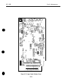
Logic Board
Logic Board (Top View)
Logic Board (Bottom View)
VII
Page
3 -10
3 -14
3 -16
3 -16
3 -21
3 -24
3 -25
4 -13
4 -14
4 -24
4 -26
4 -29
443
446
447
5- 6
TABLE 3TABLE 3TABLE 3TABLE 3TABLE 3TABLE 3TABLE 3TABLE 4TABLE 4TABLE 4TABLE 4TABLE 4TABLE 4TABLE4TABLE4TABLE 5-
1
2
3
4
5
6
7
1
2
3
4
5
6
7
6
1
QUICK REFERENCE FOR SElTlNG
ERROR INDICATIONS
DEFAULT SETrING MODES
DEFAULT SETTING MODE FUNCTION SETrINGS
SELF-TEST PRINT MODES
HEXADECIMAL DUMP TEST PRINT
DEFAULT SETTING WHEN RESETrING THE EEPROM
PRINTING MODES AND HEATING METHODS (1)
PRINTING MODES AND HEATING METHODS (2)
LIST OF BJ CARTRIDGE SIGNAL CONTACTS
HEAD INSTALLATION STATUS AND SIGNAL DETECTION
INK CONSUMPTION DURING CLEANING (AS A STANDARD)
LIST OF SENSOR FUNCTIONS
LIST OF SCANNER CARTRIDGE SIGNAL CONTACTS
LIST OF SCAN MODE
TOOLS REQUIRED FOR HEAD GAP ADJUSTMENT
VIII
BJC-4300
Part 1: Safety and Precautions
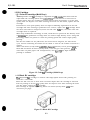
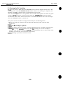
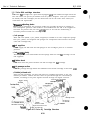
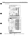
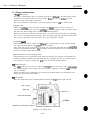
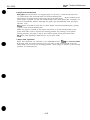
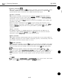
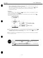
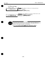
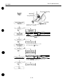
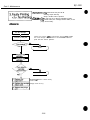
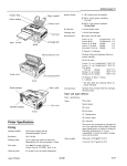
1 .l Moving Parts
The moving parts
of the printer are shown below. They include the carriage belt, idler
roller, carriage, slow down gear, paper feed roller, pressure roller, eject roller, spurs.
and pick-up roller. The first three parts above are driven by the carriage motor while
the latter are driven by the paper feed motor. Avoid getting hair, clothing, personal
ornaments, etc., caught in these moving parts.
Also note that the spurs are made of metal and have sharp edges. Avoid touching these
spurs with bare hands.
Carriage
\
I
Paper Feed Motor
Slow Down Gear
Pressure Rollers
baper Feed Roller
Figure l-l Moving Parts of the Printer
l-l
BJC-4300
Part 7: Safety and Precautions
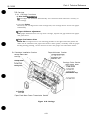
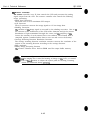
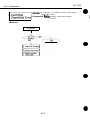
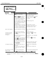
1.2 Ink Stains
1.2.1 Ink path
Do not touch the ink path while servicing as the ink can stain hands, work table,
clothing, etc.
The ink path consists of the E%J cartridge nozzles, head cap, head wiper, maintenance
jet receiving section, and waste ink absorber.
In the case of color J3J cartridges, the cartridge’s ink outlets and joint pipes are also
part of the ink path.
I
1
Caution!
Although the ink is non-toxic, it contains organic solvents.
Isopropyl alcohol 67-63-0, glycerin 56-81-5, and ethyleneglycol 107-21-l
in black ink and isopropyl alcohol 67-63-O in color inks. Do not get ink it
your eyes and mouth. If any ink should get into your eyes, wash out wit1
plenty of water and consult a doctor. If a large amount of the ink is
consumed, consult a doctor immediately.
Give the doctor the information on the BJ cartridge label. Since the ink
contains dyes, any ink stains on clothing, etc., are permanent.
BJ Cartridge
Head Wiper
Figure 1-2 Ink Path
I
BJC-4300
Part 1: Safety and Precautions
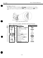
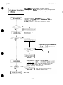
Black BJ Cartridge
Color BJ Cartridge
Figure 1-3 Ink Path of the BJ Cartridge
1.2.2 Ink mist
The E3J cartridge ejects ink onto the paper. During prolonged or heavy-duty use of the
printer, the small amounts of ink mist which splatter off the paper during printing can
contaminate the inside of the front cover and platen.
Clean any contaminated parts with a soft moist cloth. Ink in such areas can
contaminate the back of the paper and dirty hands and clothing while servicing.
Figure 1-4 Ink Mist
1-3
BJC-4300
Part 1: Safety and Precautions
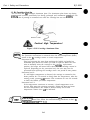
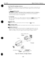
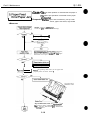
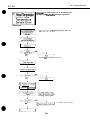
1.3 BJ Cartridge Heat-Up
Do not touch the BT cartridge’s aluminum plate. The aluminum plate heats up during
prtnting and becomes particularly hot during prolonged and continuous printing. It can
overheat also if printing is continued even after the cartridge has run out of ink.
Aluminum Plate
/
Caution! High Temperature!
Figure l-5 BJ Cartridge Aluminum Plate
a
NOTE
The printer has a protective mechanism when the FM cartridge heats up.
The protective mechanism is activated when the head temperature (diode)
sensor in the BJ cartridge senses a certain temperature.
Protection level 1:
This level prevents the user from touching the bubble jet head’s hot
aluminum plate when the bubble jet head is replaced. When the user
tries to manually move the carriage to the cartrIdge replacement
position, the beeper will sound three times and the cartridge cannot be
replaced. Depending on the protection level, the user may even be
prevented from replacing the cartridge until a set period of time passes.
Protection level 2:
If a still higher temperature is detected, the carriage is returned to the
home position for 3.5 seconds to bring down the temperature. After the
resting period, printing will resume. This continues for over 20 seconds
to lower the bubble jet head’s temperature.
Protection level 3:
If the temperature continues to increase, a head temperature error
occurs. This stops the printing operation. If this still does not lower
the head temperature, the sensor is deemed faulty and a head
temperature sensor error will be indicated.
is stopped by a head temperature errc~r or a head
sensor error, follow the troubleshooting procedures in Par? 5;
6.TROUBLESHOOTlNG (page 5-10).
1-4
BJC-4300
Part 1: Safety and Precautions
2.1 Handling BJ Cartridges
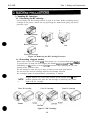
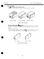
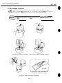
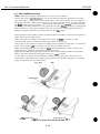
2.1.1 Unpacking the BJ cartridge
Do not unpack the BJ cartridge until it is ready to be used. Before installing the BJ
cartridge in the printer, remove the cap protecting the nozzles and gently peel off the
protective tape.
1
2
Color BJ Cartridge
Black BJ Cartridae
Tape
Photo BJ Cartridge
Figure 1-6 Removing the BJ Cartridge Protector
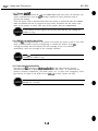
2.1.2 Preventing clogged nozzles
Never touch or wipe the nozzles with tissue paper, etc. to prevent them from CIogging.
To prevent dirt or dried ink from clogging the nozzles however.install the BJ cartridge
immediately in the printer or in the cartridge container after removing the cap and
peeling off the protective tape.
Do not attempt to reuse the cap or tape as doing so can cause print defects.
Do not store the color BJ cartridge with the ink cartridge removed.
BJ cartridges cannot be disassembled, reassembled, or washed.
NOTE
a
Clogged nozzles can cause white streaks across printed areas . If this
problem persists even after the ink cartridge is cleaned by the printer,
replace the BJ cartridge.
Black BJ Cartridge
Color BJ Cartridge
Figure 1-7 BJ Cartridge
1-5
Photo BJ Cartridge
BJC-4300
Pati 1: Safety and Precautions
2.1.3 Power on/oft
When the printer is turned off with the POWER button and auto power off function, the
printer automatically caps the ElJ cartridge’s nozzles for their protection and to
prevent ink leakage.
If the DC power cord is disconnected before the printer is turned off with the POWER
button, the nozzles will not be capped. In such cases, reconnect the DC power cord,
start up the printer as usual, then turn off the printer with the POWER button.
If the nozzles are not capped, the ink may leak and dry out causing the
nozzles to clog.
2.1.4 When not using the printer
Keep the BJ cartridge installed in the printer even when the printer is not in use. Also
keep it installed while carrying, transporting, or storing the printer. If the E%J
cartridge’s package has been opened but the cartridge is not to be installed
immediately, store the cartridge in the cartridge container.
If the ELI cartridge is removed from the printer, ink may leak and dry out
causing the nozzle to clog.
2.1.5 Ink electroconductivity
The ink in the ESJ cartridge is electroconductive. If ink leaks into the printer’s
mechanical parts, use a damp paper towel, etc., to wipe clean. If it leaks into the
printer’s electrical components, use tissue paper, etc., to wipe clean completely; If ink
gets into the IC chips on the PCB and it is difflcult to clean, replace the PCB.
Never turn on the printer if ink has leaked inside the printer. It may
damage the circuitry.
l-6
BJC-4300
0
Part 1: Safety and Precautions
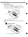
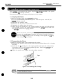
2.2 Handling Ink Cartridges
2.2.1 Unpacking the ink cartridge
Do not unpack the ink cartridge until it is ready to be used. Before installing it in the
color E?J cartridge, remove the cap covering the ink outlets.
Cap
\
Figure l-8 Removing the Ink Cartridge Cap
2.2.2 Preventing clogging
To prevent poor ink suction due to clogging of the joint pipes, never touch the ink
cartridge’s ink outlets. After removing the cap from the ink cartridge. promptly install
the ink cartridge in the BJ cartridge to prevent the nozzles from clogging due to driedout ink and dust, etc. Do not remove an ink cartridge from E3J cartridge unless
replacing.
Color Ink Cartridge
Yellow Ink Outlet
Black Ink Cartridge
Magenta Ink Outlet
(Contact Section
of the Joint Pipe)
‘Black Ink Outlet
(Contact Section
of the Joint Pipe)
Figure 1-9 Ink Cartridge Protection
1-7
BJC-4300
Part 1: Safety and Precautions
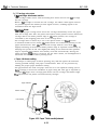
2.3 Printer Precautions
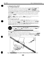
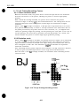
2.3.1 Spur deformation prevention
Do not deform the tips of the spurs.
The spurs come into contact with the paper after printing. As the actual contact
surface is small, any ink adhering to the spurs is minute and wiped off by the spur
cleaners. Therefore any ink on the spurs is not enough to contaminate the paper as it
passes. However, if the spurs become deformed, their contact surface with the paper
increases, causing more ink to adhere to each spur. Since the spur cleaner is unable
to wipe off all the ink, a line of dotted ink may mask the printed paper.
Figure l-10 Spurs and Spur Cleaner
2.3.2 Static electricity damage prevention
The static charge that accumulates in your body from clothing can damage electrical
components. Therefore never touch the electrical contacts of the carriage ribbon cable
and E3J cartridge.
Figure l-11 Carriage Ribbon Cable’s Electrical Contacts
1-8
BJC-4300
Part 1: Safety and Precautions
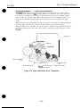
2.3.3 Ink leakage prevention
Do not pack, transport, or store the printer without a BJ cartridge installed. Without
a BJ cartridge installed, the ink in the purge unit will leak and disperse inside the
printer. When packing the printer, make sure the carriage is at the capping position
(the right end of the platen).
The EU cartridge’s nozzles are capped automatically when the power is turned off with
the POWER button. Do not disconnect the DC power cord before turning off the printer
with the POWER button. Otherwise, the nozzles will not be capped.
Figure 1-12 Capping Position
2.3.4 Waste ink adhesion prevention
When the printer is turned off with the POWER button, the printer automatically drives
the gears in the purge unit (the maintenance jet receiving section) to remove waste ink
on the gears. If waste ink remains on the gears, it may dry out and affect the purge
unit’s operation.
Do not disconnect the DC power cord before turning off the printer with the POWER
button. OtherwIse, the printer will not drive the gears to remove the waste ink. Always
press the POWER button to turn off the printer before disconnecting the DC power
cord.
1-9
BJC-4300
Part 7: Safety and Precautions
2.4 Scanner Precautions
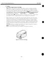
2.4.1 Scanner Cartridge Protection
Do not touch the scanning head of the scanner cartridge as it may affect the quality
and ability of the scanning operation. When cleaning the scanner lens, wipe gently
with a soft damp cloth and wipe off any excess moisture with a soft dry cloth or paper.
To avoid damage caused by miscontact or static charge, do not touch the contact
terminals. Scanner cartridge cannot be disassembled, reassembled, or washed.
Scanning head
Contact terminals
Figure 1-13 Scanner Cartridge
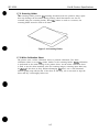
2.4.2 Scanning Precautions
The scanning document should be placed between the scanning holder to prevent
staining or scratching. Do not feed thick or bent paper. Also direct feeding of thin
paper or comer-folded paper may result in paper jamming.
Figure 1-14 Scanning Holder
l-10
BJC-4300
Pari 1: Safety and Precautions
3.1 EEPROM Data Precautions
The printer keeps track of various settings, the total waste ink amount, and the total
sheets printed with the black, color and photo EU cartridges. This data is stored in the
EEPROM on the logic board. Note the following precautions during servicing:
1) Before servicing
Check the EEPROM data with a test print. The total sheets printed can give you an
idea of how much the printer has been used.
2) During logic board (EEPROMI replacement
Always visually check the waste ink amount absorbed by the waste ink absorbers
and replace them when necessary as explained in Part 5: 4.3 Logic Board and Waste Ink
Absorber Replacement Cautions (page 5-5).
If the waste ink absorbers are not visually checked regularly, they may reach or
exceed their full capacity before “waste ink full” is detected. The waste ink may
therefore start leaking.
The memory data for the replacement logic board (EEPROM) is not defined.
Therefore, after replacing the logic board (and EEPROM), reset the total waste ink
amount to zero by clearing the data.
3) After waste ink absorber replacement
After replacing the waste ink absorbers, reset the total waste ink amount to zero by
clearing the EEPROM data.
After the EEPROM is reset, the data it contained cannot be printed out
with a test printout. If you want to check the stored data, be sure to
execute test printout before resetting the EEPROM.
When the stored data is reset, the various settings, the total count of
printed sheets, and the total waste ink amount will all be reset. The total
sheets printed and waste ink amount cannot be input using the control
panel.
Immediately after the printer is started, it keeps track of the estimated
waste ink amount based on the usage conditions. To prevent ink leakage
when the waste ink amount exceeds the waste ink absorption capacity, the
printer stops printing and indicates an error when the waste ink
absorption capacity is close to being full.
For details on checking the EEPROM data with a test printout and for
clearing the data, see Part 3: 3.6 EEPROM Reset(page 325).
If the printer stops operating in the case of a waste ink full error, follow the
countermeasures described in Part 5: 6. TROUBLESHOOTING (page 5-70).
l-11
BJC-4300
Part 1: Safety and Precautions
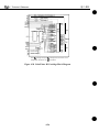
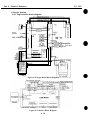
3.2 Static Electricity Precautions
‘Ike static charge accumulated in the body from clothing can damage electrical
components. To dispel the build-up of static electricity, touch a metallic object that is
grounded. Be sure to do this before disassembling the printer for servicing. Before
dispelling your static charge build-up, do not touch the electrical contacts on the logic
board and on the carriage ribbon cable (see Figure l-l 1) while the carriage ribbon cable
is connected to the logic board.
Electrostatic Discharge!
\
AC
Adapter
Figure 1-15 Electrical System of Printer
1-12
BJC-4300
0
Part 1: Safety and Precautions
3.3 Disassembly and Reassembly Precautions
printer is comprised of a large number of plastic parts. When disassembling the
printer, take care not to break or bend plastic hooks.
The
Since some plastic parts contain glass fibers for extra rigidity and
precision, but since their viscosity is low. plastic hooks can break easily
when excessive force is used. Use a precision screwdriver, and do not pull
plastic hooks with excessive force while unhooking them.
Never apply excessive force
when releasing a hook.
Figure 1-16 How to Release Plastic Hooks
3.4 Self-Diagnosis
printer has a self-diagnosis feature to detect hardware defects. The results of the
self-diagnosis are indicated by the indicators and the beeper. For details, see Part 3:
3.1 Error indications (page 3- 14).
The
1-13
BJC-4300
Part 1: Safety and Precautions
This page intentionally left blank
1-14
Part 2: Product Specifications
BJC-4300
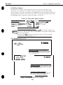
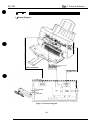
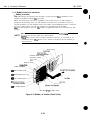
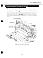
1.1 Product Outline
This printer is a value added, full color bubble jet desktop printer that enjoys the
realization of high image printing through the implementation of the PhotoRealism
concept.
This printer achieves high image printing by adopting “drop modulation technology” in
the color ELJ cartridge and the photo E3J cartridge.
The expanded printing environment has allowed the printer to have banner printing
capabilities. The printer can also be used as a compact color scanner when the optional
scanner cartridge is installed in the carriage.
All the function settings are easfly set by the personal computer. The operation is easily
performed with the bidirectional Centronics interface (effective only for the device ID
response)
This printer uses a built-in AC adapter. This is a small and light weight personal color
printer with high performance capabilities.
Cut Sheet Feeder
Front Cover
SJ Cartridge Containe
Parallel lntertace Connector
Paper Output Tray
Paper Output Tray Extension Guide
Manual Feeding Slot
Figure 2-1 Printer Exterior
2-1
BJC-4300
Part 2: Product Specifications
1.2 Features
1. Compact (desk-top size)
Dimensions: 383 mm W x 231.6 mm D x 203 mm H
Weight: Approx. 3.5 kg (7.7 lbs) (including color BJ cartridge)
2. Built-in AC adapter employs a high-current capable switching power supply, power
saving control is not performed with print duty.)
3. Automatic power control (auto power on/ofiJ
4. High quality printing of 720 x 360 dpi (in both monochrome and black when using
the special printer driver)
5. tie standard built-in printer control modes
LQ mode (EPSON LQ-2550 emulation)
BJ mode (IBM Proprinter X24E emulation)
[Canon extended mode is supported when using the canon printer driver.1
6. User replaceable BJ cartridge and adopting drop modulation technology color/
photo BJ cartridge
Color BJ Cartridge
Drop modulation technology has been adopted.
(Multi drop)
It has separate ink cartridges (Bk) (Y, M, C!) and the head with
136 nozzles in a vertical line: 64 nozzles (Bk) + 24 nozzles x 3
(Y, M, Cl.
Black BJ Cartridge
Contains the black ink and the head with 128 nozzles.
Depending on each sales territory, it is not packed with the
printer, but is available separately.
Photo BJ Cartridge Drop modulation technology has been adopted.
(Multi drop)
It has integrated ink cartridges with the head with 136 nozzles
in a vertical line; 64 nozzles (Bk) + 24 nozzles x 3 (y, M, C).
Black ink cartridge
Black ink cartridge for the color &I cartridge.
Color ink cartridge
T&color (Y, M, C) ink cartridge for the color BJ cartridge.
(*Previous color and photo BJ cartridges that do not use drop modulation
technology may be used, however the printing quality will be the same as when drop
modulation technology is not used.)
7. Device ID compatible to “Plug and Play”
(Responds only to the device ID/status of nibble mode)
8. Banner printing capabilities.
9. Capable of the double paper feeding with the leverless cut sheet feeder and manual
feed. (It is possible to feed paper manually even when the paper has been set on the
cut sheet feeder.)
10. Photo quality printing using the Photo kit option and the photo printing special
driver.
11. Cartridge container packed with the printer.
12. High quality photo image input using the option color image scanner cartridge.
2-2
BJC-4300
Part 2: Product SDecifications
1.3 BJ Cartridge
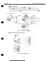
1.3.1 Color BJ cartridge (Multi Drop)
The disposable color EJ cartridge is comprised of a 136.nozzle print head and two
replaceable ink cartridge (black and color).When the ink runs out or more than 6
months elapse after the cartridge has been removed from its package, or if the print
quality does not improve even after cleaning the head over five times, replace the ink
cartridge.
Furthermore, if the print quality does not improve following replacement of the ink
cartridge and after cleaning is performed over 5 times, replace the EIJ cartridge. Since
the three color Inks are integrated, when one ink color runs out, the entire color ink
cartridge must be replaced.
When drop modulation technology is used, small dots are printed in low density areas
to mtnimtze the graininess and large dots are used for high density areas. Using this
technology allows the printer to retain its printing speed and achieve high quality
printing.
The first 24 nozzles are for yellow ink, the second 24 for magenta, the third 24 for
cyan, and the remaining 64 nozzles are for black. A total of 136 nozzles are lined in a
vertical.
About 160 sheets (in HQ mode with 1500.character pattern) can be printed with the
black ink and about 90 sheets (in HQ mode, 7.5% duty per color pattern) with the
color inks. On plain paper and transparencies, 360 dpi/720 dpi high-resolution
printing is available.
Figure 2-2 Color Bj Cartridge (Multi Drop)
1.3.2 Black BJ cartridge
The disposable BJ cartridge is used for ultra-high-speed mono-color printing. Its
head has a 128 nozzle.
When the ink runs out or more than 6 months elapse after the cartridge is removed
from its package or if the print quality does not improve even after cleaning the head
over five times, replace the EIJ cartridge.
This cartridge is capable of printing about 700 sheets (in HQ mode with 1500
characters per page).
Figure 2-3 Black BJ Cartridge
2-3
BJC-4300
Part 2: Product Specifications
1.3.3 Photo BJ Cartridge (Multi Drop)
he disposable photo J3J cartridge used for printing color photographs, integrates a
136.nozzle print head and four ink cartridges.
When the ink runs out or more than 6 months elapse after the cartridge has been
removed from its package, or if the print quality does not improve even after cleaning
the head over five times, replace it with a new photo ESJ cartridge. Since the four color
inks are integrated, when one ink color runs out, the entire photo J3J cartridge must
be replaced. Adopting drop modulation technology, the photo BJ cartridge prints
small dots in low density areas to minimize the graininess and large dots in high
density areas to retain its printing speed and achieve high quality printing.
The first 24 nozzles are for yellow ink, the second 24 for magenta, the third 24 for
cyan, and the remaining 64 nozzles are for black. A total of 136 nozzles are lined in a
vertical. About 50 sheets (in Photo mode) can be printed.
Use high quality special paper and Canon original printer driver for printing.
Figure 2-4 Photo BJ Cartridge (Multi Drop)
1.4 BJ Cartridge Container
The cartridge container is for storing unused E?J cartridges black, color and photo to
protect the head from damage. When storing a FIJ cartridge in this container, be sure
to close the cover. When storing a color EJ cartridge, do not remove the ink cartridges.
The BJ cartridge containers can be linked together
Figure 2-5 BJ Cartridge Container
1.5 AC Adapter
The AC adapter supplies DC power (5 VDC and 24 VDC) to operate the printer.
Figure 2-6 AC Adapter
2-4
BJC-4300
Part 2: Product Specifications
1.6 Consumables
1.6.1 BJ cartridges (Color, Black, Photo)
Replacement BJ cartridges are identical to those included with the printer.
Color BJ Cartridge
Black BJ Cartridge
Photo BJ Cartridge
Figure 2-7 BJ Cartridges
1.6.2 Ink cartridge (Color BJ cartridge)
Replacement ink cartridges are the same as those installed in the color ink cartridge
and black ink cartridge. Either cartridge can be used for half a year after the seal is
opened.
Numbers of sheets printed
Color ink cartridge: Approximately 90 sheets (HQ mode) (7.5% duty per color pattern)
Black ink cartridge: Approximately 160 sheets [HQ mode) (1500 characters)
Color Ink Cartridge
Black Ink Cartridge
Figure 2-8 Ink Cartridges
2-6
BJC-4300
Part 2: Product Specifications
1.7 Option
1.7.1 Color Image Scanner Cartridge
This printer can be used as a color scanner when a scanner cartridge is installed.
The scanner cartridge is a replaceable scanner unit that uses a one-line 128 pixel
CCD. The scanner separates each of the three RGB colors of the LED by scanning
the same line three times. The color image is output by 8.bit signals (256 gradation in
each RGB primary color). For a monochrome image, the image is lit with a green LED
and scanned once to output either a 8.bit or a-bit signal. The maxtmum scanning
resolution is 360 dpi x 360 dpi.
To stabilize LED output, the printer preheats and warms the scanner cartridge when
the installed scanner cartridge remains at rest or scanning is not performed.
White calibration must be conducted using the white calibration sheet when white
balance and shading correction is performed. White balance correction is needed to
correct the uneven density in the horizontal direction caused by variation of LED.
Shading correction is needed to correct the uneven distribution of light transmitted
through the center and the periphery of the lenses. Density variation between each
vertical scanning line caused by the varying sensitivities of the CCD pixels, is also
corrected.
The calibration data is retained unless there is an ambient temperature change of
+5”C or the cartridge is removed and reinstalled.
Also for monochrome printing, edge emphasis processing is performed.
Figure 2-9 Scanner Cartridge
2-6
BJC-4300
Part 2: Product Specifications
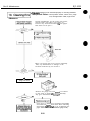
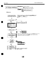
1.7.2 Scanning Holder
The scanning holder protects the scanning document from the printer’s sharp spurs
that may damage the document during feeding. Small documents can also be
scanned using the scanning holder. When the printer is used as a scanner, the
scanning holder must be used at all times.
Figure 2-10 Scanning Holder
1.7.3 White Calibration Sheet
The printer uses a white calibration sheet to perform calibration. The white
calibration sheet is set on the printer similar to the scanning holder. White calibration
is performed in the initial setting of the printer driver. As the white calibration sheet
is used to set the white standard value for scanning images, scanning input data may
be tiected if the sheet is dirty. Without damaging the sheet, use a soft moistened
cloth to gently wipe off the dirt If the sheet is still dirty, use a wet towel to wipe the
sheet and dry it thoroughly before use.
2-7
BJC-4300
Part 2: Product Specifications
2.1 Printer Specifications
1. Type
Desk-top serial color bubble jet printer
2. Paper feeding method
Auto feeding and manual feeding
3. Cut Sheet Feeder capacity
Plain paper: Maximum 10 mm (approximately 100 pages of 64g/m2 paper)
Envelopes: 10 envelopes (Commercial number 10 and DL)
Transparencies: 50 sheets
BPF: 10 sheets
Glossy film/ BJ cloth: One page with the manual feeding
Scanning document: Place between the scanning holder. One page with the ASF.
4. Manual feeding slot capacity
One sheet
6. Paper weight
Automatic feed / Manual feeding slot: 64 to 105 g/m* (17 Ibs to 28 lbsl
6. Printing speed
Burst
Color BJ Cartridge (Black printing)
Black BJ Cartridge (Black printing)
346 cps (10 cpi)
510 cps (10 cpi)
7. Printing direction
Unidirectional
@‘rlnt direction is automatically changed according to optimum printing directional
COtltKl1.l
8. Printing width
Maximum 8”
9. Line feed speed
150 Ins/line (2/6” line]
10. Built-in printing control modes
LQ mode: Epson a-2550 emulation
BJ mode: IBM Proprinter X24E emulation
[Canon extended mode is supported when the Canon driver is used.)
11. Line feed pitch (n: programmable)
LQ mode: l/6”, l/8”, n/60”, n/72”, n/180”, n/216”, and n/360”
BJ mode: l/6”, l/8”, n/180”, and n/360”
2-8
Part 2: Product Specifications
BJC-4300
11. Printing characters
Typefaces:
LQ&BJ mode
Pitch:
LQ mode
M mode
Character matrix: HQ mode
HS mode
LQ mode
Character set:
Roman, Gothic, Courier, prestige, Script, Draft
10. 12. 15, 17, 20 cpi, and PS
10, 12, 17 cpi ,and PS
36 (H) x 48 [v) dots
18 out of 36 (H) x 48 M dots
Italic character set and Graphic character set
and International character set
IBM character set 1, 2
and all character set
(code page 437,850, 852 860,863 and 865)
BJ mode
12. Number of columns printed
LQ mode
Mode
10 CDi
10 cpi doublewide
10
10
12
12
12
12
15
15
cpi condensed
cpi condensed-doublewide
cpi
cpi
cpi
cpi
cpi
cpi
doublewide
condensed
condensed-doublewide
doublewide
Proportiond spacing
BJ mode
10 cpi
10 c& doublewide
10 cpi condensed
10 cpi condensed-doublewide
12 cpi
12 cpi doublewide
Proportional spacing
* cpl: characters per line
Pitch
10 cpi
5 cpi
17 cpi
8.5 cpi
12 cpi
6 cpi
20 cpi
15
7.5
PS
10
5
17
8.5
12
6
13. Bit image
Vertical: 8.24 and 48 dots
Horizontal: 60, 120, 180, 240,360 and 720* dpi
* In smoothing mode or when using the Canon driver.
14. BUS%
LQ mode
J3J mode
Receive buffer
22 kB
22 kB
Download buffer
32 kB
OkB
15. Interface
IEEE1284 compatible parallel interface
2-9
10
PS
cpi
cpi
cpi
cpi
cpi
cpi
cpi
cpi
cpi
cpl *
80 cpl
40 cpl
136 cpl
68 cpl
96 cpl
48 cpl
160 cpl
80 cpl
120 cpl
60 cpl
Varies
80 cpl
40 cpl
136 cpl
68 cpl
96 cpl
48 cpl
varies
BJC-4300
Part 2: Product Specifications
16. BJ cartridge
Color BJ cartridge (Multi Drop)
Type: Color BJ cartridge with replaceable ink cartridges
Print head: 136 nozzles (vertically-lined) Bk (64 nozzles) + Y, M, C (24 nozzles x 3)
Ink colors: Black, cyan, magenta, yellow
Service life:
Approximately 160 pages (in the HQ mode with 1500 character pattern) with a
black cartridge
Approximately 90 pages (in the HQ mode) with a color cartridge (7.5% duty per
color pattern)
Weight: Approximately 85 g (3.0 oz) [including black and color ink tanks)
Black BJ cartridge
Type: Black BJ cartridge with integrated ink
Print head: 128 nozzles (vertically-lined)
Ink color: Black
SewIce life: Approximately 700 pages (in the HQ mode): cartridge
Weight: Approximately 85 g (3.0 oz)
Photo BJ cartridge [Multi Drop)
Type: Color BJ cartridge with integrated ink
Print head: 136 nozzles (vertically-lined) Bk (64 nozzles) + Y, M, C (24 nozzles x 3)
Ink colors: Black, cyan, magenta, yellow
Weight: Approximately 74 g 12.8 oz)
17. Sensor functions
Paper out: Provided
Installation of cartridge: Provided
BJ cartridge/Scanner cartridge identifkation:
Waste ink amount: Provided
Ink out: None
Paper width: None
Provided
IS. Acoustic noise level
Approximately 45dB IA)/ HQ (Sound pressure level: According to IS0 9296)
19. Ambient conditions
Temperature
During operation
I
5°C to 35°C
I
During storage
0°C to 35°C
Humidity
20. Power source
USA/Canada
UK/Australia
Europe
1 Voltage/Frequency
AC 120V 60 Hz
AC 240V 50 Hz
AC 230V 50 Hz
Power consumption
Stand-by status
Max. 30 W
Max.4W
21. Dimensions
383mmWX231.6mmDX203mmH
22. Weight
Approximately 3.5 kg (7.7 lbs) (including BJ cartridge)
2-10
BJC-4300
Part 2: Product Specifications
2.2 Scanner Cartridge Specifications (Option)
l.Tppe
Cartridge replacement type color scanner
2. Image *ensor
128 pixel in one line of CCD
5. Light source
3-color LED (RGB), (alignment of red, green, blue, green, red ; five in total)
Using green LED for monochrome printing
4. Scanning method
Sequential RGB light source switching method
5. Scanning direction
Unidirectional
6. Picture sign&II output
Color Shit (256 gradation for each of RGB colors), Binary. Grayscale Bbit
7. Resolution
Carriage scanning direction; 360/300/200/ 180/90 dpi
(300/200dpi are the resolution change from the software)
Paper feed direction: 360/ 180/90 dpi
8. Scanning speed (reference exclude paper pickup/ delivery and data tmnsfer time)
Color, Bbit, ECP, A4:
4’31” (360 x 360 dpi), 2’56” (180 x 180 dpi), 2’31” (90 x 90 dpi]
Monochrome, lbit, ECP, A4:
0’34” (360 x 360 dpi), 0’29” (180 x 180 dpi), 0’25” 190 x 90 dpi)
9. Interface
ECP/Nibble
10. Document feeding method
Place the document between the scanning holder and feed it through ASF.
11. Calibration
Scanning the white calibration sheet corrects the shading and white balance
12. Edge stress
Edge stress processing only applies to monochrome binary
13. Power consumption
Approx. 1.6 W
14. External dimensions
43.8 mm (wl x 41.8 mm (D) x 72.2 mm (H)
15. Weight
Approx. 60 g (2.1 oz)
2-11
BJC-4300
Part 2: Product Specifications
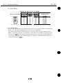
2.3 Paper Specifications
2.3.1 Paper size
Letter (8.5” x 11”)
Legal (8.5” x 14”)
A5 (148 mm x 210 mm)
A4 (2 10 mm x 297 mm)
Commercial number 10 envelope (9.5” x 4.1”)
European DL-size (220 mm x 110 mm)
2.3.2 Paper type (Recommended)
Plain paper
Bubblk jet paper (Canon LC-301)
Coated paper (Canon coated paper Lc-101)
Envelope (Commercial number 10 or European DL)
Transparencies (Canon transparency ftlm CF- 102)
BPF (Canon back print film BF- 102)
Glossy photo paper (Canon glossy paper GP-201)
High gloss paper [Canon high gloss Film HG- 10 1)
Fabrtc (Fabric sheet FS- 10 1)
Banner (Banner paper)
2.3.3 Print paper
Media
Thickness Lever
Plain paper
E
Paper Feed
Flap
Method
Sheet feeder
Limit
sosition
10mm
Flat
Upright
High resolution paper
Envelopes
Center
Sheet feeder
10mm
Right
Sheet feeder
10
Flat
Transparencies
Center
Sheet feeder
50 sheets
Upright
Back print film
Center
Center
Right
Sheet feeder
Sheet feeder
Sheet feeder
10 sheets
1 sheet
Upright
Glossy photo paper
Banner paper
1 sheet
Upright
Fabric sheet
High gloss film
Center
1 sheet
1 sheet’1
Upright
Upright
Right
Sheet feeder
Manual feed slot
2-12
Upright
BJC-4300
a
Part 2: Product Specifications
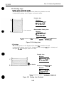
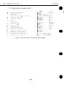
2.3.4 Printing range
1)Flainpaperand specialmedia
The shaded portion in the diagram below shows the printable area and
recommended printing area for paper and special media.
Printable Area
Minimum
L 3.4 mm 0.13”‘1
R 3.4 mm 0.13”
T 3.0 mm 0.12”
B 7.0 mm 0.27”
*Feed direction
Recommended Printing Area
Minimum
L 3.4 mm 0.13-I
R 3.4 mm 0.13”
T 20.5 mm 0.81”
B 20.5 mm 0.81”
*l :LTR is selected in the EJ setup utility pogram, L is 6.4mm(0.25”) minimum.
Figure 2-11 Printing Area
2) Envelope
The shaded portion in the diagram below shows the printable area and
recommended printing area for U.S. Commercial 10 envelopes [9.5 X 4.1 inches) and
European DLsize envelopes (229 X 110 mm).
Printable Area
Minimum
L 6.4 mm 0.25”
R 10.4 mm 0.41”‘1
T 3.0 mm 0.12”
B 7.0 mm 0.27”
* Feed direction
Recommended Printing Area
Minimum
L 6.4 mm 0.25”
R 10.4 mm 0.41”‘1
T 20.5 mm 0.61”
B20.5 mm 0.61”
‘1:For Commercial number 10 envelopes,31.4mm(l.2”).
Figure 2-12 Printing Area (Envelope)
2-13
BJC-4300
Part 2: Product Specifications
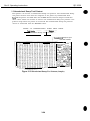
2.4 Interface Specifications
‘Ihe parallel interface sends 8 bits (one byte) of data at a time and is transistortransistor-logic (rrz) compatible.
The interface cable must be constructed of American Wire Gauge [AWG) No. 28 or
larger. The maximum length of the twisted-pair shielded cable must be 2.0 m
(approximately 6.6 feet).
1) Interface Type
IEEE1284 compatible parallel interface
2) Data transfer
8-bit parallel interface
3) Signal voltage levels
Low: 0.0 v to +oa v
High: +2.4 V to +5.0 V
4) Input/ output
Each signal pulled up with +5V.
51 Interface cable
Type: Twisted-pair double shielded cable
Material: AWG#26 or larger
Length: Up to 2.0 m (6.6 feet)
6) Interface connectors
On printer: Amphenol 57-40360 (or equivalent)
On cable: Amphenol 57-30360 (or equivalent)
71 Input/ output signals and pin layout
Corn
No.
1
tible mode
i
2
3
4
5
6
7
8
9
10
11
12
13
14
15
16
17
18
L
Signal
STROBE
DATA1
DATA2
DATA3
DATA4
DATA5
DATA6
DATA7
DATA8
ACKNLG
BUSY
P.E.
SELECT
AUTO FEED XT4
N.C’Z
INIT
GND
T
I/O
No.
Signal
IN
IN
IN
IN
IN
IN
IN
IN
IN
OUT
OUT
OUT
OUT
IN
19
20
21
22
23
24
25
26
27
28
29
30
31
32
33
34
35
36
STROB&ET1
DATAl-RET
DATA2-RET
DATA%RET
DATA4-RET
DATAB-RET
DATAG-RET
DATA7-RET
DATA8-RET
ACKNLG-RET
BUSY-RET
P.E.-REX
INIT
ERROR
GND
N.C+5.ov3
SELECT IN-
IN
N.C’S
* 1. Al-RETs are connectec
1 GND.
‘2. N.C means no connection.
*3. The level is pulled up with +5.OV through 5.6kQ resistor.
*4. These signals are effective only in LQ printer control mode.
2-14
110
....
...
.
IN
OUT
...
.
IN
BJC-4300
Part 2: Product Specifications
Nibble mode
No.
Signal
110
No.
Signal
1
HostClk
Data1
Data2
Data3
Data4
Data5
Data6
Data7
Data8
PtrClk
PtrBusy
AckDataReq
xflag
HostBusy
N.C.”
Gnd
Gnd
IN
IN/OUT
IN/OUT
IN/OUT
IN/OUT
IN/OUT
IN/OUT
IN/OUT
IN/OUT
OUT
OUT
OUT
OUT
IN
19
20
21
22
23
24
25
26
27
28
29
30
31
32
33
34
35
36
Signal Cnd
Signal Gnd
Signal Gnd
Signal Gnd
Signal Gnd
Signal Gnd
Signal Gnd
Signal Gnd
Signal Gnd
Signal Gnd
Signal Gnd
Signal Gnd
Init
DataAvail
N.C.”
N.C.”
N.C.”
1284Active
2
3
4
5
6
7
6
9
10
11
12
13
14
15
16
17
18
*1: 1\
VCC
k:. [Non Connection]
II0
..
..
1..
IN
OUT
...
..
IN
ECP mode
No.
1
2
3
4
5
6
7
8
9
10
11
12
13
14
15
16
17
18
‘1: 1\
Signal
HostClk
Data 1
Data2
Data3
Data4
Data5
Data6
Data7
Data8
PeriphClk
PeriphAck
A&Reverse
xflag
HostAck
N.C.
Gnd
Gnd
VW
:. [Non Connection]
110
No.
IN
IN/OUT
IN/OUT
IN/OUT
IN/OUT
IN/OUT
IN/OUT
IN/OUT
IN/OUT
OUT
OUT
OUT
OUT
1N
19
20
21
22
23
24
25
26
27
28
29
30
31
32
33
34
35
36
2-15
l/O
Signal Gnd
Signal Gnd
Signal Gnd
Signal Gnd
Signal Gnd
Signal Gnd
Signal Gnd
Signal Gnd
Signal Gnd
Signal Gnd
Signal Gnd
Signal Gnd
ReverceReq
PeriphReq
N.C.”
N.C.”
N.C.”
1284Active
...
...
...
IN
OUT
...
IN
BJC-4300
Part 2: Product Specifications
8) Input/ output signals:
Compatible Mode
STROBE [Input]
This signal is used to read DATA1 to DATAS. The signal becomes valid after BUSY
signal goes Low and the printer outputs an ACKNLG signal. The host computer
does not send the next signal until it receives ACKNLG signal. It is normally High,
after becoming Low. the printer receives data. When the signal remains Low, the
printer does not operate until it goes High.
DATA1 to 8 [Input]
‘Ihe printer receives data with the STROBE signal. The state of each bit of the
signal must be maintatned for at least 0.5 p’s from the rising edge of the STROBE
signal.
ACKNLG [Output]
This signal is a response signal to the STROBE signal. The host computer does not
send the next STROBE signal until this signal is sent. When the power is turned on
or the BUSY signal goes Low for the input of the INIT signal, this signal is sent
regardless of the STROBE signal.
BUSY [Output]
When this signal is High. the printer is BUSY; when Law, the printer is READY. The
signal goes high when data is received, when the printer is offline, or when an error
occurs (paper-out, paper jam).
P.E. [Output]
When the printer cannot feed paper, this signal goes High. Then BUSY signal goes
High and the SELECT and FAULT signals go Low. The signal goes Low when the
paper is set and the printer goes online. FAULT and SELECT signals then go High
from Low. If paper is not ejected [paper Jam) by executing a paper eject command.
this signal and BUSY signal go High, and SELECT and FAULT go Low. In this case,
the signals do not change even if the paper is ejected.
SELECT [Output]
The printer is SELECT when this signal is High. The printer is DESELECT when
this signal is Low. This signal goes Low when the printer is offline, when an error
occurs (paper-out, paper jam, head error, etc.).
AUTO FEED XT [Input] (Valid in LQ mode)
When this signal is Low, automatic ltne feed mode (Carriage Return and Line Feed)
is effective.
The printer judges the level of this signal only when it is turned on or is initialized
by the INIT signal.
INIT [Input]
INIT from the system resets the printer to its initial power-on state. In BJ mode, the
BUSY line goes high, and any received data is printed. In LQ mode. the BUSY line
goes high, and the print buffer is cleared. When INIT goes low. it resets the printer
to the power-on default state.
FAULT [Output]
This signal goes Low when the printer is in an error state [paper-out, paper jam, etc.).
SELECT IN [Input] (Valid in LQ mode)
When this signal is High, the DC1 and DC3 codes are valid: When Low. they are
invalid. The printer Judges the level of this signal when it is turned on or is
initialized by the INIT signal.
2-16
BJC-4300
Part 2: Product Specifications
Nibble Mode
Host Clk [Input]
STROBE signal to read DATA 1 to DATA 8.
Negotiation phase:
Trigger signal to send the protocol confirmation to the printer.
DATA I-8 [Input]
The printer receives data with the Host Clk signal.
The state of each bit of this signal must be maintained for at least 0.5 ps from the
rising edge of the Host Clk signal.
Ptr Clk [Output]
Reverse data transmission phase:
The printer requests the host computer to read the data by making the Ptr Clk
Signal Low. After finishing reading, the host computer notifies peripheral
equipment of completion of data receiving by making the Host Busy signal High.
Ptr Busy [Output]
Reverse data transmission phase:
Indicates bit 3 and bit 7 of the transmission data.
Ack Data Req [Output]
*Reverse data transmission phase:
Indicates bit 2 and bit 6 of the transmission data.
*Negotiation phase:
Trigger signal to inform the host computer of the printer’s condition [whether it
supports nibble mode or not, whether there is reverse transmission data or not).
Xflag [Output]
*Reverse data transmission phase:
Indicates bit 1 and bit 5 of the transmission data.
*Negotiation phase:
Informs the host computer whether the printer supports nibble mode or not,
synchronizing with the falling edge of the Ack data Req signal. “L” means that it
supports nibble mode.
Host Busy [Input]
*Reverse data transmission phase:
Indicates that the host is ready to receive the data from the printer by making the
Host Busy signal Low. After that, it goes high to synchronize with the Low pulse of
Ptr Clk signal to verify receiving data.
*Reverse idle phase:
The Host Busy signal goes high in response to the Low pulse of the Ptr Clk signal,
and enters the reverse data transmission phase again.
INIT [Input]
When this signal becomes “L”, the printer’s state becomes BUSY. When the signal
changes from “L” to ‘?I”, it resets the printer control system to the initial state.
This signal is normally “H” and the pulse width must be at least 0.5 ps at the
printer side.
After initializing, the printer enters compatible mode.
DataAvsi/ [Output]
*Reverse data transmission phase:
Indicates bit 0 and bit 4 of the transmission data.
*Negotiation phase:
Informs the host computer if there is reverse transmission data or not to
synchronize with the falling edge of the Ack Data Req signal. “L” means that there
is reverse transmission data.
2-17
BJC-4300
Part 2: Product Specifications
1284 Actlve [Input]
This signal coni%ms that the printer is a 1284 compatible device when 1284 Active signal
goes High and Host Busy signal goes Low. It goes Low with the termination phase.
ECP Mode
Host Clk [Input]
This signal handshakes with the PeriphAck signal when data is transferred form the
host computer to the printer. A Low Host Clk signal indicates that data has been
output along the data buses (Datal-8).
The signal goes High as a response to a High PerlpbAck signal. It remains High
during reverse data transmission.
Data I-8 [Input/Output]
This signal is an input signal when data is transferred from the host computer to
the printer. During reverse data transmission, this is an output signal and the
printer uses this data bus to send data to the host computer.
Periph Clk [Output]
When data is transferred from the printer to the host computer, this signal remains
High. Periph Clk signal is lowered during reverse transmission phase and indicates
that data has been sent to the host computer. This signal is also High in response
to the High HostAck signal from the host computer.
Perlph Ack [Output]
Periph Ack signal goes Low when the printer is ready to receive data from the host
computer. Once the data is received the signal goes High. During the reverse data
transmission phase, this signal indicates whether the data sent from the printer to
the data bus was a “command” or “data”.
Low: “Command”, High: “Data”
Ack Reverse [Output]
Ack Reverse signal remains High when data is transferred from the host computer
to the printer. During the reverse data transmission phase, the signal remains Low.
‘Ihe Reverse Request signal from the host computer goes Low to request a switch
from the forward data transmission phase to the reverse data transmission phase.
In response to the Low Reverse Request signal, Ack Reverse signal goes low to
indicate that the request was accepted.
When the Reverse Request signal from the host computer goes High to request a
switch from the reverse data transmission phase to forward data transmission
phase, Ack Reverse signal goes high to indicate the switch over request has been
accepted.
X flag [Output]
This signal remains High in ECP mode.
Host Ack [Input]
This signal indicates the nature of the signal along the data bus when data is
transferred from the host computer to the printer. A Low Host Ack indicates a
“command” whereas a High Host Ack indicates a “data”.
During reverse data transmission, this signal handshakes with the Periph Clk
signal. when the host computer is ready to accept data from the printer, this signal
goes Low. After data is received the signal goes High.
2-18
BJC-4300
Part 2: Product SDecifications
Reverse Req [Input]
This signal goes Low when the recovery process (data re-transmission) is taking
place during data transmission from the host computer to the printer.
In response to a Low Ack Reverse signal, Reverse Req signal goes High.
When switching from the idle state of the forward data transmission phase to the
reverse data transmission phase, i.e. data is transferred from the printer to the host
computer, this signal goes Low.
The Low period indicates it is in the reverse data transmission phase.
When the reverse data transmission phase is switched to the forward data
transmission phase, this signal goes High.
Periph Req [Output]
If the printer requests reverse data transmission during the forward data
transmission, this signal goes Low. When the host computer switches over from the
forward data transmission phase to the reverse data transmission phase, together
with the Ack Reverse signal, the Periph Req signal goes High in response to the host
computer’s Low Reverse Request signal.
1284 Active [Input]
During the negotiation phase, this signal goes High and remains High during ECP
mode to indicate bidirectional operation.
After ending the ECP mode, this signal goes Low and enter the termination phase.
LQ Mode
0.5~s i.okLs 0.5ps
Mtn. M i n . M i n .
BJ Mode
0.5ps 1 .ops 0.5&S
M i n . M i n MI”.
Figure 2-13 Timing Chart (Compatible Mode)
2-19
BJC-4300
Part 2: Product Specifications
Figure 2-14 Timing Chart (Nibble Mode)
Host Ack
Host Clk
Periph Clk
Periph Ack
Periph Req
Xflag
Figure 2-15 Timing Chart (ECP Mode)
2-20
BJC-4300
Part 2: Product Specifications
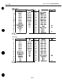
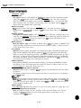
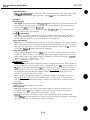
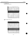
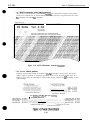
2.5 Character Code Tables
2.5.1 BJ mode
a) USA Code page 437
b] Multilingual Pqe 850
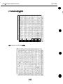
Part 2: Product Specifications
c) Turkish Code Page 852
d) Portuguese Code Page 860
BJC-4300
BJC-4300
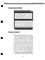
Part 2: Product Specifications
e) Canadian French Code Pqe 863
2-23
BJC-4300
Part 2: Product Specifications
2.5.2 EPSON mode
a) Epson Italics Character Set
b) Epson Graphics Character Set
2-24
BJC-4300
Part 2: Product Specifications
c) International Character Set
2-25
BJC-4300
Part 2: Product SDecifications
This page intentionally left blank
2-26
Part 3: Operating instructions
BJC-4300
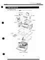
1.1 Equipment Check
After unpacking the printer, make sure the items below are included:
Documentation
BJ Cartridge
\
If
Packing
Figure 3-1 Packaging
3-1
AC Adapter
BJC-4300
Part 3: Operating Instructions
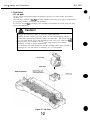
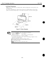
1.2 Printer Dimensions
The printer’s dimensions are shown below. Allow enough space for the printer to be
used with ease.
For banner printing leave a space about the size of an M-size paper in front of the
printer. Also allow enough space at the back of the printer to set the banner paper.
Figure 3-2 Printer Dimension
a
NOTE
Do not place the printer in excessive heat or humidity.
Operate the printer under the following conditions:
Ambient temperature:
5°C to 35°C
10% to 90% (no condensation)
Relative humidity:
Do not place the printer in direct sunlight.
Do not place the printer near a device containing a magnet or that
generates a magnetic field.
Place the printer on a level and stable surface.
. Do not place the printer in areas subject to vibration.
Keep the printer clean.
When moving the printer, hold both ends.
3-2
BJC-4300
Part 3: ODeratina Instructions
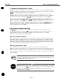
1.3 Setup Procedure
set up the printer as follows.
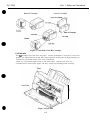
1.3.1 Connecting the interface cable
1) Make sure both the printer and the computer are off.
2) Connect one end of the parallel interface cable to the parallel interface connector
on the back of the printer.
After connecting the cable, fasten the locking arm to secure it.
3) Connect the other end of the interface cable to the parallel interface connector on
the computer.
Figure 3-3 Connecting the Interface Cable
1.3.2 Connecting the AC adapter
Connect the DC power cord’s plug to the printer’s DC jack and plug in the AC adapter
into a power outlet.
Figure3-4 Connecting the DC Power Cord
Do not press the POW/S button while connecting the DC power cord. If
the DC power cord is connected while the POWEF1 button is pressed, the
EEPROM reset mode in service functions are executed.
3-3
BJC-4300
Part 3: ODeratina Instructions
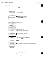
1.3.3 Turning on the printer
Before turning on the printer, first turn on the computer and any other peripheral
equipment. Make sure the DC power cord has been connected properly, then press
the POWER button to turn on the printer. When turned on, the printer executes
initializing operations. Finally, the carriage stops at the cartridge replacement
position and the POWER indicator blinks to indicate that the printer is on standby.
1.3.4 Installing the cartridge
Two types of cartridges can be installed in the printer: a color and black BJ cartridge.
1) Removing the BJ cartridge protectors
Take out the BJ cartridge from the package, then remove the cap and tape on the
nozzles as shown in the figure.
1
Tape
Photo BJ Cartridge
Figure 3-5 Removing the BJ Cartridge Protectors
Do not reuse the cap and tape, as doing so can clog the nozzles or mix the
ink colors.
Do not touch the nozzles when removing the tape. Scratching the head
face and ink contamination may result in the poor printing.
Do not shake the BJ cartridge after removing the cap and tape, as ink may
leak from the cartridge.
Figure 3-6 BJ Cartridge Handling Precautions
3-4
BJC-4300
Part 3: Operating Instructions
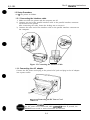
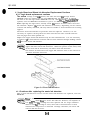
21 Instfdlim! the cartridge
Open the printer’s front-cover and flip up the cartridge lock lever. Insert the
cartridge into the carriage and push down the cartridge lock lever to lock the
cartridge in place. When pressing the CARTRIDGE button, the beeper sounds once
and the carriage moves to the capping position.
a
NOTE
If the cartridge is not properly installed while holding down the
CARTf?/DGE button, the beeper will sound twice and the carriage will not
return to the capping position. After installing the cartridge, be sure to
close the front cover securely. If it is not closed properly, paper feed and
printing problems may occur.
When installing the scanner cartridge, all the LEDs are lit at 75% power
output at the home position for max. 100 sec., and preheated to stabilize
the LED output. The computer will display a message saying ‘Warming
up scanner cartridge. Please wait.” will appear. After the message
appears, all the LEDs are lit at 50% power output for max. 600 sec. to
retain the temperature.
Figure 3-7 Cartridge Installation
3-5
BJC-4300
Part 3: Operating Instructions
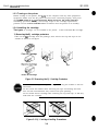
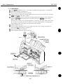
3) Replacing the cartridge
Open the printer’s front cover and press the CARTRDGE button the beeper sounds
once and the carriage mcwes to the replacement position. Then flip up the cartridge
lock lever and remcwe the cartridge. Install another cartridge by following ‘Installing
the cartridge” above. Always store an unused BJ cartridge in the E3J cartridge
container. The E%J cartridge may be stored alternately in the BJ cartridge container.
If the printer has been operating for a prolonged period. the E3J cartridge’s
aluminum plate will get hot. When the aluminum plate gets hot, holding
down the CARTRlDGE button will sound the beeper four times and the
carriage will not move to the cartridge replacement position. In such
cases, wait a few minutes before replacing the BJ cartridge. Do not move
the carriage by hand.
3-6
BJC-4300
Part 3: Operating Instructions
1.3.5 Replacing the ink cartridge
When a color E+J cartridge is used, the ink cartridges can be replaced as follows:
1) When to replace the ink cartridge
Replace the ink cartridge in any of the following cases: The ink has run out, the ink
cartridge has been out of its package for over six months, or the print quality does
not improve even after the cartridge is cleaned five times. The color ink cartridge
contains three colors. If one ink color runs out, the entire color ink cartridge must
be replaced.
If an ink cartridge has been replaced but the print quality does not improve even
after cleaning, replace the color BJ cartridge with a new one.
2) Removing an ink cartridge
Move the carriage to the cartridge replacement position as described in 1.3.4
3) Replacing the cartridge (page 3-6). Then take out the ink cartridge to be replaced as
shown in the figure below.
Ink adheres to and around the ink cartridge’s ink inlet, so handle the
cartridge with care.
Figure 3-8 Removing the Ink Cartridge
3) Installing an ink cartridge
Take out the new ink cartridge from its package and remove the cap as shown in the
figure. Install the ink cartridge by following the removal procedure in reverse.
After installing the ink cartridge, press the CARTRIDGE button the beeper sounds
once and tlx carriage returns to the capping position.
Figure 3-9 Removing the Ink Cartridge Cap
BJC-4300
Part 3: Operating Instructions
1.3.6 BJ cartridge container
A EU cartridge container for storing the BJ cartridge is packed with the printer.
Always store an unused EiJ cartridge in the BJ cartridge container. The box can store
one BJ cartridge only, but several containers can be joined together.
a
NOTE
The BJ cartridge container can be attached to the printer.When storing a
color J3J cartridge make sure that the black and color ink cartridges are
installed.
When Storing the Color BJ Cartridge
When Storing the Black or Photo BJ Cartridge
L---___------- /
When Storing the Scanner Cartridge
Figure 3-10 BJ Cartridge Container
3-6
BJC-4300
Part 3: Operating Instructions
1.4 Turning the Printer On/Off
1.4.1 Turning the printer on
With the printer connected to a power source, press the POWER button to turn on the
printer. When the printer turns on, the beeper sounds cmce and InitIalizIng
operations are executed. If a cartridge has not been installed, the carriage will move
to the cartridge replacement position and the POWER indicator blinks to indicate that
a cartridge must be Installed. If a BJ cartridge has already been installed, the POWER
indicator will light to indicate that the printer is ready. When the printer is turned on
after more than 72 hours have passed since the last cleaning operation, the printer
automatically carries out a cleaning operation before printing or after the printer is
turned on.
[When a color EJ cartridge is installed, the first cleaning is executed after 24 hours.)
‘Ihe POWER indicator blinks while the cartridge is being cleaned.
1.4.2 Turning the printer off
To turn off the printer, press the POWER button. When the printer is turned off, it
executes a power-off operation to cap the EJ cartridge. When the scanner cartridge is
installed, the carriage will move to the carriage replacement position, i.e. the same
position as when there is no cartridge installed, before the power is turned off. When
the power-off operation is complete, the POWER indicator turns off. Make sure the
POWER indicator is off, before disconnecting the AC power cord.
Never turn off the printer by disconnecting the AC power cord without first
pressing the POWER button. OtherwIse, the printer turns off before it can
cap the E3J cartridge. If the BJ cartridge is not capped, the ink may leak
or dry out in the nozzles.
When the POWER button is pressed to turn off the printer, the power-off operation to
cap the E3J cartridge is executed even if errors have occurred.
Any error occurring after the power-off operation starts is ignored. Also, if the POW/S
button is pressed while the cartridge is being cleaned, the POWER indicator continues
blinking until the cleaning is completed. After cleaning is completed, the ELI cartridge
is capped and the printer turns off.
Figure 3-11 Do not turn off the printer without pressing the POWER button first
3-9
BJC-4300
Part 3: Operating Instructions
1.5 Paper Settings
For optimum printing, the printer has various paper settings to suit various types of
paper. Set the paper selection lever before loading the paper.
TABLE 3-1 QUICK REFERENCE FOR SETTING
Thickness Lever -
Media
Plain paper
High resolution paper
Envelopes
Center
Right
Transparencies
Back print film
Center
Glossy photo paper
Banner paper
Center
Fabric sheet
High gloss film
Center
Right
Right
Center
T
!
Flap
Position
Pauer Feed
7Limit
Method
Flat
Sheet feeder
10mm
Sheet feeder
10mm
Upright
Sheet feeder
Sheet feeder
10 envelopes
Flat
50 sheets
10 sheets
Upright
Sheet feeder
Sheet feeder
1 sheet
Sheet feeder
1 sheet
Sheet feeder
Manual feed slot
1 sheet
1 sheet”
f
Upright
Upright
Upright
Upright
Umiaht
* 1 Slide one sheet all the way into the manual feeding slot.
1.6 Banner Print
When printing on banner paper, lower the paper support and set the paper delivery flap
to the upright position. To avoid misfeeding, put a light crease between the first and
second page and set the first page in the sheet feeder. Place the rest of the banner
paper behind the printer. Do not use the manual feeding slot to avoid skewing.
Each top margin for banner printing is set at Omm. However, to avoid printing on the
platen, printing will start 3mm from the initia top margin. Set an extra sheet at the
end in case the bottom edge is not printed on the last page.
Banner printing uses a large amount of ink. To avoid ink shortage, use of a new ink
cartridge before banner printing is recommended.
Paper Delivery Flap
Output Tray Extention Guide
Figure 3-12 Banner Print
Part 3: Operating Instructions
BJC-4300
1.7 Name of the Parts and Their Functions
The different parts of the printer and their functions are shown below.
Cut Sheet Feeder
Holds a stack of
Aligns the cut sheets in the cut sheet feeder
according to the paper size. A maximum
paper width of 241 mm (9.64 in.) can be set.
Autofeeds banner paper and scanning document.
Open to install or remove the cartridge. set
the paper thickness lever, or remove the jams
paper.
Paper Output Tray
Pulls out to receive the printed sheets.
AC Adapter
Installed on the rear of the
printer, the AC adapter
supplies power from the power
outlet to the printer.
Depending on the location of
purchase, the power cable is
permanently attached to the
AC adapter where as in some
areas the power cable is
detachable.
Parallel Interface Connector
Connects the printer to the
parallel port on the computer.
Figure 3-13 Name of the Parts and Their Functions
3-11
BJC-4300
Part 3: Operating Instructions
POWEf? Button
Turns the printer on or off.
POWER/ERROR Indicator This signal indicator functions
_
as both the power indicator
and error indicator. This
indicator lights green to
indicate that power is on
(normal state). The indicator
lights orange to indicate an
error, when the printer runs
out of paper, for example.
RESUME Button
This key has the following
functions:
-To recover an error, press once and release.
-To feed a sheet of paper into the printer, press once and release.
-To eject a sheet of paper already loaded in the printer.
-To start cleaning the print head, press and hold down for over two seconds.
CARTRIDGE Button
Moves the carriage to the EIJ
cartridge or ink cartridge
replacement position.
Paper thickness lever
-
Adjusts the gap betwween the
print head and the paper. Set
this lever according to the type
of print media that you are
using.
Figure 3-14 Name of the Parts and Their Functions
Paper thickness lever
Adjusts the gap between the print head and paper according to the thickness of the
paper. There are three settings: left for printing with the black EIJ cartridge on plain
paper: center for printing with the color/photo BJ cartridge on plain paper or high
resolution paper, transparencies, back print film, glossy paper or high glossy film
and scanner cartridge: and right for thick paper, envelopes and banner paper.
Figure 3-15 Paper Thickness Lever
3-12
Part 3: Operatina Instructions
BJC-4300
When carrying or transporting the printer. keep the EIJ cartridge installed in the printer
or stored in the EIJ cartridge container.
This prevents the ink from leaking and drying out in the nozzles
2.1 Carrying the Printer
Follow the procedure below when carrying the printer.
1) Press the POWER button to turn off the printer. When the power turns off, the
POWEFl indicator turns off.
2) Disconnect the interface cable.
3) Disconnect the AC power cord from the AC outlet.
4) Unplug the AC adapter from the printer.
5) Check that the AI cartridge is at the capping position (the right end of the printer).
If the cartridge is not at the capping position, move the carriage belt by hand until
the cartridge reaches the capping position.
4lD
’
I
Never turn off the printer by disconnecting the AC power cord without first
pressing the POWER button. Otherwise, the printers turned off before it
can cap the FSJ cartridge. If the BJ cartridge is not capped, the ink may
leak or dry out in the nozzles.
2.2 Transporting the Printer
Follow the procedure below, when transporting the printer.
1) Disconnect the interface cable and AC power cord as described above in 2.1. Carrying
the printer.
2) Check that the ELI cartridge is at the capping position (the right end of the printer).
If necessary, move it to the capping position by hand. Fasten the carriage to the
right end of the printer with tape.
3) Repack the printer in its original box and packing materials.
Tape
Figure 3-16 Fastening the Carriage
a
NOTE
If the original packing materials are not available, use a sufficient amount
of shock-absorbent material.
3-13
BJC-4300
Part 3: Operating hstructions
3.1 Error indications
The indicators in combination with the beeper indicate the nature of errors.
POWER Button
RESUME Button
/
/
POWER/ERROR indicator
Figure 3-17 Control Panel
TABLE 3-2 ERROR INDICATIONS
State
7
KJsercorrectableermmI
Paper pick-up error
Paper jam
Cartridge mode mismatch
u3ewn-~e errors]
ROM error
RAM error
Cartridge displaced error
Home position error
Waste ink full error
Temperature sensor error
print position correction error
Head temperature error
Headtem~~sensorenvr
Cleaning error
Scanner cartridge disolaced error1
POWER/ERROR
Beeper
orange
Orange
orange
Once
Twice
5 times
Green
Green
Green
Green
Green
Green
Green
Green
Green
Green
Green
3-14
t)
t)
c)
tf
t)
tf
tf
t)
c)
t)
t)
Orange
Orange
Orange
Orange
Orange
Orange
Orange
Orange
Orange
Orange
Orange
Once
Twice
3 times
4 times
5 times
6 times
7 times
8 times
9 times
LO times
L 1 times
BJC-4300
Part 3: Operating instructions
The errors listed in Table 3-2 are described below.
User-correctable errors (Correctable by removing the paper and pressing the RESUME
button).
1) Paper pick-up error
Occurs when the paper cannot be fed properly.
2) Paper jam
Occurs when the printed paper cannot be ejected.
3) Cartridge mode mismatch
Occurs when the scanning operation is performed with a EJ cartridge installed.
Occurs also when printing with a scanner cartridge installed (including Self Test
printing).
User-uncorrectable errors. (Press the POWER button to turn off the power.)
4) ROM error
Occurs when the ROM check during the initializing operation fails.
5) RAMermr
Occurs when the RAM check during the initializing operation falls.
6) Cartridge displaced error
Occurs when the printer does not detect the cartridge other than during cartridge
replacement.
7) Home Position Error
Displayed when the home position can not be detected.
6) Waste ink full error
Occurs when the “total waste ink amount” recorded by the EEPROM exceeds the
prescribed limit.
9) Temperature sensor error
Occurs when the temperature sensor’s [THl) reading on the control board is
irregular.
10) Print position correction error
Occurs when the print position correction cannot be detected.
11) Head temperature error
Occurs when the temperature of the diode sensor in the W cartridge head
exceeds the prescribed level.
12) Head temperature sensor error
Occurs when the diode sensor in the BJ cartridge head is assessed as irregular.
(The head temperature error always occurs before this error occurs.)
13) Cleaning error
Occurs when the cleaning operation detection at the capping position is irregular.
14) Scanner cartridge displaced error
Occurs when the scanner cartridge is recognized but the scanner ID is incorrect.
Occurs when the calibration data sent from the computer is incorrect.
3-15
BJC-4300
Part 3: ODeratina Instructions
3.2 Function Settings
Use the windows driver or &I setup utility program for MS-DOS to set the function
settings.
The five default setting modes can be set with the POWER button after the printer is
turned on.
3.2.1 Setting the default setting mode
The default setting mode can be set as follows:
When turning on the printer, hold down the POWER button until the beeper sounds the
specified number of times. In this way, the following default setting modes can be set.
TABLE 3-3 DEFAULT SETTING MODES
Mode
Beeper
Remarks
USA/M2
6 times
Factory default setting for USA model
7 times
USA/BJ
Europe, Asia/LQ 8 times
Europe /SJ
9 times
Asia, UK/W
10 times
Factory default setting for the models excluding USA model
Function settings of each default setting mode.
TABLE 3-4 DEFAULT SETTING MODE FUNCTION SETTINGS
Control mode
Paper selection
Print mode
Smoothing setting
Auto power on
Auto power off
Font selection
Code page selection
Page length setting
Character set setting
Text scale function
Download buffer setting
Receive buffer size
Automatic line feed
Automatic carriage return (BJ only)
AGM setting (BJ only)
--setiingww I
USA
ILQ
W
LTR
USA
IBJ
EiJ
LTR
RQ
Off
Off
Off
Roman
437
22”
kaphics
Off
Off
22KB
CR
UQ
Off
Off
Off
Courier
437
11”
set1
Off
Off
22Kl3
CR
LF
Off
...
USA
Europe,
Europe
Aeia/LQ
IBJ
LQ
A4
BJ
A4
W
Off
Off
HQ
Off
Roman
437
22”
kaphics
Off
Off
22KB
CR
...
USA
3-16
Off
Off
Off
Courier
850
12”
Set2
Off
Off
22KS
CR
LF
Off
Asia, UK
IBJ
ElJ
A4
RQ
Off
Off
Off
Courier
437
12”
set2
Off
Off
22KB
CR
LF
Off
BJC-4300
Part 3: Operating Instructions
3.2.2 BJ setup utility program
Save F i l e . . .
Print tlode
Delete Files . . .
Paper Size
Buffer Size
*to Power Off
fluto Power On
P r i n t Test Patterns
Printer Settings
Change Ink Cartridge
Clean Print Head
Preset settings
:I24
:Input Buffer
:Disable
:DisabIe
I
so
Phe next time ~)au want to use the s e t t i n g s ,
just open the file and press FlB to send
settinga to the printer.
Figure 3-18 BJ Setup Utility Program (Sample)
Function settings which can be set with the l?J setup utility program.
Here is a short summary of the BJ s&up utility program features. For further details,
type EU on the command line to start the utility program and scroll through the online help.
Advanced Settings
These settings include all the settings for either BJ mode or LQ mode. The
advanced settings are all on the second screen of the l3.J setup utility program.
AGM
Turns alternate graphics mode (AGM) on and off in E%J mode. Turn on AGM for IBM
Proprinter X24E emulation.
Auto Carriage Return
Sets how the printer performs a carriage return.
Auto Line Feed
Sets how the printer does a line feed in E%J mod? or LQ mode.
Auto Power Off
Sets the printer to turn itself-off automatically when it has not received data for a
certain period of time.
Auto Power On
Sets the printer to turn itself on automatically after it receives data.
Buffer Size
Allows you to change the allocation of available space in the buffer.
Change Ink Cartridge
Moves the cartridge holder to the center of the platen so you can change the
cartridge.
3-17
Part 3: Ooerafina Instructions
Em-4300
Character Set
Code pages and character sets may vary according to the make of the computer
and printer. For the BJ mode. Character Set 1 or set 2 can be selected. In LQ
mode, epson italic or graphics set can be selected.
Clean Print Head
Cleans the BJ cartridge print head. If white streaks or other flaws appear on the
printed page, clean the print head.
Code Page
Allows you to select a code page in either BJ mode or LQ mode. Pages are tables
that show how characters, symbols, and numbers are coded.
Delete File
Deletes a file and settings. Delete files that are no longer needed
Eject Page
Ejects paper or other media currently loaded in the printer.
Font Typeface
Allows the selection of one of 5 typefaces: Roman, Gothic, Courier, Prestige, Script
in either &J mode or LQ mode. This setting is ignored when the software
application specifies a font.
International C.S.
Allows you to select a character set, characters and symbols specific to each
country in LQ mode.
Line Feed
Sends a line feed (LF) instruction to the printer and the printer feeds the loaded
sheet one line.
Open File
Opens a saved file and retrieves the printer and advanced settings that it holds.
After opening a file, press FlO to srnd the settings to the printer and close the E&J
setup utility program.
Page Length
Sets the page length for BJ or LQ mode
Paper Size
Sets the paper size. Selections inrlude A4, Letter, #lO Envelope (3.4 mm), DL
Envelope (6.2 mm).
Power Off
Turns off power to the printer.
Preset Settings
You can select one set of defaults from a list. Each set is named by country and
control mode. For example, you can choose USA (LQ) or USA (EM).
Print Mode
Sets the print mode for HQ (high quality), HS (high sperd) and Fine.
3-18
BJC-4300
Part 3: Operating Instructions
Print Test Patterns
Prints a test pattern so you can check printer operation with the new settings you
have just made. Before you execute this command, be sure the printer can load A4
or Letter-size paper. A Demonstration of printer features, Test Print A (repeating
ripple pattern), and a Nozzle Pattern Print can be printed.
Printer Control Mode
Sets the emulation mode for the printer: BJ mode and LQ mode, Automatic mode.
Printer Port
The printer is attached to parallel port LPTl by default. To connect your printer to
a different port, make an appropriate selection here: LpTl, LFI’2 and LPT3.
Printer Settings
Prints a list of all the current printer settings. Be sure to use Letter-size or A4
paper to print this list.
Reset Printer
Takes the new printer and advanced settings you have just made and stores them
as the new default settings for the printer.
Save File
Saves a file with the settings made in the menus
Smoothing
Smoothing removes the ragged edges that appear on characters and curved lines.
These so called ‘gaggies” are caused by a stair-stepping effect caused by creating
characters and lines with individual dots when printed.
Text Scale Mode
Provides compatibility with software that assumes 66 lines will fit on each page for
either BJ or LQ mode.
3-19
BJC-4300
Part 3: ODeratino Instructions
3.3 Cleaning the BJ Cartridge
Turn on the printer. Hold down the RESUME button until the beeper sounds twice. The
cleaning starts when the POWER indicator blinks. When the cleaning is completed, the
blinking stops. Thr cleaning time is approximately 22 seconds.
After the cleaning, execute a test printout of thr nozzle check pattern to check the print
quality. With the printer turned on, hold down the POWER button until the beeper
sounds four times, then release the button to conduct the off-line test. The test stops
when the RESUME button is pressed on.
The printer cleans the E&J cartridge automatically at the following times:
1)When the printer is turned on for the first time after the power cord has been
connected.
2)After the E?J cartridge is replaced.
3)After an ink cartridge is replaced.
4)After the printer has been on for 72 hours following the last cartridge cleaning with a
black ELJ cartridge installed. When the color W cartridge or its ink cartridge is
installed, only the first cleaning is canied out automatically after 24 hours (after that,
cleaning is carried out at an interval of 72 hours).
5)After printing a prescribed number of dots.
3-20
BJC-4300
Part 3: Operating Instructions
3.4 Self-Test Printout
This printer has built-in self-test functions which can be executed without any
connection to a computer. The off-line, self-test operations are described below.
After turning on the printer, hold down the POWER button until the beeper sounds the
specified number of times, then release the button. The self-test printout stops when
the RESUME button is pressed or when the printer is turned off.
TABLE 3-5 SELF-TEST PRINT MODES
Printout Mode
Beeper -Pages
]
Demonstration print
Once
Printer status infomlation print Twice
ASCII character print
3 times
Nozzle check pattern
4times
a
NOTE
printed
contimlous printing
1 Page
continuous printing
lP%X
All self-test prints require Letter or A4-size paper. Using a smaller size
paper for a self-test print will result in parts of the printout being printed
directly on the platen.
Self-test prints arr printed in accordance with the current printing
settings (font, printing mode, etc.).
3.4.1 Demonstration print
Black BJ Cartridge
CdllOtl
BJC-4300
color Bubble Jet printer
Color/Photo EIJ Cartridge
BJC-4300
color Bubble Jet Printer
\
Figure 3-19 Demonstration Print (Sample)
3-21
BJC-4300
Part 3: Operating Instructions
3.4.2 Printer status information print
>BJ<
1
2.
3.
4.
5.
6.
7.
8.
9.
10.
11.
12.
13.
14.
Ii.
16.
17.
18.
19.
Printer Control Mode
Paper Selection
Print Mode
Smoothing (Black B.I Cartridge)
Automatic Power on
automatic Power off
Font
Code Page
Page Length
Character Set
Text Scale
Download Buffer
Receive Buffer Size
Automatic Line Feed
Automatic Carriage Return
Alternate Graphics Mode
International Character Set
Installed Cartridge Type
Printer Preset Status
:
:
:
:
:
:
Enable
I,TR
High
Qudlity
Disable
Disable
Disable
: Courier
: 43:
: llinch
:
:
:
:
:
:
:
SET1
Disable
Disable
22KB
CR-CR
T,F=LF
Disable
<--<--<-__
<_-_
Roman
437
22inch
Graphics
Disable
<--<--CR=CR
USA
: Black BJ Cdrtrldge
<--: USA-BJ
Figure 3-20 Printer Status Information Print (Sample)
3-22
>LQ<
Disable
<---
BJC-4300
Part 3: Operating Instructions
3.4.3 ASCII character print (ripple pattern)
The printer control mode, control ROM vmsion, and function settings in the header
section are printed out as shown below. The same patterns are printed for the color
E?J cartridge and black E3J cartridge
Figure 3-21 ASCII Character Printout (Sample)
3.4.4 Nozzle check pattern
Printout this pattern using all nozzles of the ELJ cartridge. In the event that print
defects appear, perform a cleaning operation of the head. If print quality does not
improve even after the cartridge is cleaned five times, replace the BJ cartridge or the
ink cartridge.
Color (Mult 3rop)lPhoto (Mult Drop) BJ Cartr!dge
(
Printed with the ,lLSf nozzle
3-23
BJC-4300
Part 3: Operating Instructions
3.5 Hexadecimal Dump Test Printout
This printer can execute a hexadecimal dump test printout. The hexadecimal dump
test prints the data sent from the computer to the printer by hexadecimal data.
Turn on the printer and hold down the POWER button until the beeper sounds five
times. Then release the button to execute the hexadecimal dump test printout. The
printout stops when the printer is turned off. The hexadecimal dump test printout
cannot be terminated with the RESUME button.
TABLE 3-6 HEXADECIMAL DUMP TEST PRINT
Hexadecimal dump test 15 times
Hexadecimal dump test print
Print data contents
______~~
-1
Excellent print
quality.
fast.
media
Print
ExcellPnt
versatili
True photo&3
ty.
rahic q u a l i t y .
Excellent s o f t
w a r e compatibili
ty...Excellent P
rint q u a l i t y . P
rint f a s t .
Exce
llent media vers
True p
atility.
hotog..rahic qua
Excellent
lity.
software rompat
ibility...ExCell
i ent p r i n t qualit
t.
Figure 3-23 Hexadecimal Dump Test Printout (Sample)
3-24
BJC-4300
Part 3: ODeratina Instructions
3.6 EEPROM Reset
The EEPROM records various settings, the data on the total number of sheets printed
and the total waste ink absorption amount for the color and black ink cartridges
respectively. The total number of sheets printed and the total wastes ink absorption
amount can serve as a reference for how much the printer has been used.
The EEPROM must be reset when the logic board or the waste ink absorber is replaced.
See Part 5: 4.3 Logic Board and Waste Ink Absorber Replacement Cautions (page 5-9, for
details.
3.6.1 EEPROM Reset
“Waste ink full’ is detected with the total waste ink absorption amount recorded in the
EEPROM. When the ink absorber is replaced, the data on the total waste ink
absorption amount in the EEPROM must be reset. Furthermore, when the logic
board is replaced, the new logic board’s EEPROM must be reset and the waste ink
absorber must be also replaced at the same time. To reset the EEPROM, follow the
procedure below.
1. While holding down the POWER and RESUME button, insert the plug of AC power
cord connected to the AC outlet into the printer, and release the button.
2. Press the POWER button, while holding down the RESUME and CARTRlDGE
buttons. (After the indicator lights orange, the long and short beepers sound once.
3. Select the default setting by pressing the CARTR/DGE button for the specified
number of times shown in the table below. (The beeper sounds each time the
CARTRlDGE button is pressed.)
TABLE 3-7 DEFAULT SETTING WHEN RESETTING THE EEPROM
~~ ~~
Green
Default setting
Table2(USA/LQ): Factory default setting for USA/ Canada
model
Table2 (USA/BJ)
Table3 (Europe, Asia/L@: Factory default setting for the
models excluding USA/ Canada
model
4. Finally, press the RESUME button. The EEPROM is cleared and the selected
default setting is written into the EEPROM.
Be careful when performing the above operation as the EEPROM data
cannot be recovered once it is reset.
3-25
BJC-4300
Part 3: Operating Instructions
3.6.2 Printing the EEPROM data
The following data recorded by the EEPROM can be printed out as described below:
1) Function setting:
Execute the self-test printouts Printer status information print.
See 3.4 Se/f-Test Printout (page 3-21).
2) Total number of sheets printed for the color and black ink cartridges respectively:
Execute the self-test print’s ASCII character printout.
See 3.4 Se/f-Test Print (page 3-21).
31 Total waste ink absorption amount:
Print out the total waste ink absorption amount as follows:
1. Install a black E%J cartridge in the printer. (The total waste ink absorption
amount cannot be printed out with the color EiJ cartridge installed.)
2. Press and hold down the POWER, RESUME button, connect the AC power cable
to the AC outlet.
3. Load a sheet of paper into the printer.
4. While pressing the RESUME button, turn on the printer. After the buzzer sounds
once, the total waste ink absorption amount will be printed out.
Figure 3-24 Sample Printout of EEPROM Data
Resetting the EEPROM will permanently erase all data contained.
3-26
Parf 4: Technical Reference
BJC-4300
0
0
-
1 .l Printer Diagram
Carriage
BJ Cartridge/
Home
Paper Feed Motor
I
---_
Scanner Cartridge
Position S e n s o r
1
-----
----I
I
I
I
Figure 4-1 Printer Diagram
4-1
BJC-4300
Part 4: Technical Reference
1.2 Initial Flowchart
The initial flowchart below shows the process from when the
printer is turned on to
when it goes online.
Software initialization
* MPUlPrinter controller initialization
. RAM check
. Temperature sensor (THI) check
*Turn on the printer
The buzzer sounds once
*The carriage motor runs
*The carriage moves to its home position
* Home position detection
- Print position correction value setting
* If it does not auto cleaning, maintenance jet is executed
l
l
The paper feed motor runs
The pick-up roller and the paper lifting plate
are set to their initial positions
*Any paper remaining in the printer is fed out.
* If it auto cleaning is not conducted, maintenance jet is executed
Figure 4-2 Initial Flowchart
4-2
BJC-4300
Part 4: Technical Reference
1.3 Print Signal Flow
The print signal flow from when the printer receives the print data to when printing is
executed is described below.
a) The print data (including the control signals) output by the computer is received by
the printer controller through the parallel interface, which is controlled by the
printer controller on the logic board. Through the dedicated bus between the printer
controller and DRAM, print data is stored in the DRAM’s receive buffer area.
b) The print data in the receive buffer is sent to the MPU and separated into control
commands and print data based on the data stored in the control ROM. The control
commands are processed in the MPU.
c) The print data is stored in the DRAM’s print buffer.
d) When the printer controller receives the command from the MPU to start printing, it
receives print data Iby DMA transfer) stored in the DRAM’s print buffer.
The printer controller converts the print data into serial data as print drive signals
and outputs the serial data to the bubble jet head. In the bubble jet head, the print
data is converted from serial signals to parallel print data for each printed line.
Printing is executed while the printer controller is controlled by the print control
signals.
The MPU controls the entire printing process by controlling the printer controller, and
motor drivers and monitoring the status of the bubble jet head and printer.
l-----k
a
Host
Computer
----
e
1.1.
Motor Drivers
l . . - - : Print Data
t : Control Signal
Figure 4-3 Printing Signal Flow
4-3
BJC-4300
Part 4: Technical Reference
1.4 Print Drive
To eject ink from the head for printing, the printer outputs control signals from the
printer controller to the BJ head.
The control signals consist of the drive control signal for ejecting ink from the head’s
nozzles and the temperature control signal for adjusting the head’s temperature so that
the amount of ink ejected is uniform.
To achieve optimum printing, both these control signals are optimized by the printer
controller and sent from the carriage ribbon cable’s signal contacts to the BJ head.
The drive frequency varies depending on the printing mode and BJ cartridge type.
1.4.1 Printing drive control
a) Black BJ cartridge drive control
The black BJ cartridge drive control is executed by dividing the head’s 128 nozzles
into 8 blocks (16 nozzles each). These blocks are further divided into odd and even
blocks (8 nozzles each). The odd blocks eject ink simultaneously and the even
blocks do so as well. The control signals for the former are the block enable 1, 2,
and 3 signals (BENB 1, 2, 3) and for the latter the signals are the even/odd enable
signals (Even/odd ENB).
The heat enable 0 and 1 &IENB 0, 1). which are the heater drive control signals for
ejecting the ink. comprise of a pre-pulse and main pulse. To constantly achieve
optinmm ink ejection, the internal conditions such as the head’s rank, printer
temperature, and head temperature are monitored and the heater drive pulse width is
varied before the pulse is output. Furthermore, the print drive signal from the printer
controller is transferred to the BJ head’s shift resistor according to the HLATCH timing.
The printing drive signal (HDATA) is latched and when the print control and heater
drive control signals are output together, the heater for the applicable nozzles is
driven and the ink is ejected.
b) Color BJ cartridge drive control
The color BJ cartridge head’s nozzle configuration differs from that of the black BJ
cartridge. Vhe black has 64 nozzles while the color has 24 nozzles each for Y, M,
and C.) Therefore, the number of nozzles in each control block is different from that
of the black BJ cartridge. Furthermore, since the heaters are driven simultaneously for
each color, the heater drive control signals used are the heat enable [HENB) 0, 1, 2. and 3
signals. All other operations are the same as for the black BJ cartridge.
For heat enable, the HENB 0, 1, and 2 signals drive the nozzle heaters for Y, M. and
C. The HENB 3 signal drives the nozzle heater for black ink.
4-4
BJC-4300
Part 4: Technical Reference
c) Color BJ Cartridge (Multi Drop) Drive Control
The multi drop type color BJ cartridge’s printbead has 136 nozzles and each nozzle
has two heaters located one infront of the other. The printing operation using this
multi drop type color BJ cartridge is (dependent/influenced] by how these heaters
are controlled.
The sequence of ink ejection is as follows. The 136 nozzles has 8 function blocks (16
nozzles/block) and each block is separated into two functional units. Hence, each
functional unit has 8 nozzles. Ink is consecutively ejected from each unit.
Selection of the nozzles to be ejected is done by BLOCK ENABLE signals 1, 2 and 3
(BENB 1,2,3) and the EVEN/ODD ENABLE signal (Even/Odd ENB). HEAT ENABLE
(HENB 0,1,2,3) is the heat drive control signal for ejecting ink.
The HEAT ENABLE signal controls ink ejection as follows:
HENB 0: signals the nozzle (black) at the back
HENB 1: signals the nozzle (black) at the front
HENB 2: signals the nozzle (color) at the front
HENB 3: signals the nozzle (color) at the back
The HEAT ENABLE signal is made up of the prepulse and the main pulse. To
optimize ink ejection, the head rank, printer’s inner temperature and head
temperature is constantly monitored. The ink is ejected by varying the HEAT
ENABLE pulse width.
Head Driving in HQ Mode (Divided into 16)
Head Driving in HS Mode (Divided into 8)
‘9 xkH* c0,0,,,pass
Figure 4-5 Printing Signals
4-5
\ Pre-Pulse
BJC-4300
Part 4: Technical Reference
1.5 Power Off Flowchart
(
Indicator blinks (green)
Cleaning and paper feeing operations are all
completed before turning off.
<In the case the carriage moves after the power is turned 0%
Motor, BJ cartridge, and buzzers all turned
Paper feed motor, initialization operation
<In the cartriage replacement mode>
1
ping
_
CaTping
J
J
lndlcator oft
1
( MPU/Printer Controller initialization 1
Figure 4-6 Power off Flowchart
If the DC power cord or AC adapter is disconnected before the printer is
turned off with the POWER button, the cartridge head might not be capped.
In this case, reconnect the DC power cord, start up tlx printer again, then
turn off the printer with the POWER button. The DC power cord or AC
adauter mav then be disconnected.
4-6
BJC-4300
Part 4: Technical Reference
2.1 Interface
The printer supports compatible mode and nibble mode which are compatible with the
bidirectional Centronics interface-standard [IEEE P1284).
Compatible mode is the same as the Centronics interface-standard protocol.
The printer supports compatible mode and ECP mode which are compatible with the
bidirectional Centronics interface-standard (IEEE P1284).
Compatible mode is the same as the Centronics interface-standard protocol.
When the printer is used in the printer mode, it only supports data transfer in
compatible mode. It does not support the ECP mode and nibble mode which enable
high-speed data transmission and reception.
The nibble mode and the ECP mode which supports high speed data transfers have
bidirectional compatible data buses. These modes are used when status data such as
device ID and printer status as well as scanned data read from the optional scanner
cartridge are transferred to the host computer. However, the setting in the host
computer must be nibble mode or ECP mode to be applicable.
4-7
BJC-4300
Part 4: Technical Reference
2.1 .l Compatible mode
The parallel interface___for the compatible mode transfers data in S-bit units. Data is
transferred with the STROBE, BUSY, and ACKNLG handshake signals.
When the printer receives the data (Data 1-8) and STROBE signal from the host
computer and the STROBE signal is low, the printer controller (which controls the
parallel interface) outputs the BUSY signal and latches the data. After the BUSY
signal is output, the printer controller sends the latched data from the DRAM bus to
the receive buffer in the DRAM. After the data is completely written into the receive
buffer in the DRAM, the printer controller outputs the ACKNLG signal and sets the
BUSY signal to “Low.” Then it watts for the next data input from the host computer.
LO Mode
asps 1 .op o.!$s
Min. Min. Min.
BJ Mode
0.5p 1 .ops osws
Min. Min. Min.
Approx. 6~s
Figure 4-7 Interface Timing (Compatible Mode)
BJC-4300
Part 4: Technical Reference
2.1.2 Nibble mode
In nibble mode, the printer transfers data twice to the host computer in 4-bit units.
The data is transferred with the F’trClk signal and HostBusy signal handshakes.
After the printer contlrms that the HostBusy signal is low, it prepares S-bit data,
lowers the FTrClk signal and outputs the lower 4.bits along the control signal line.
After the PtrClk signal is low, the host computer receives the data and raises the
HostBusy signal. Next, after the printer cont3rms that the HostBusy signal is low for a
second time, it outputs the upper 4-bits along the control signal line. If there is no
data to be sent to the host computer after the HostBusy signal is high, the DataAvail
signal becomes high and the printer stands by for the next data transfer.
Figure 4-8 Interface Timing (Nibble Mode)
4-9
BJC-4300
Part 4: Technical Reference
2.2 720 dpi Printing/Smoothing Feature
2.2.1 Canon extension mode
In Canon extension mode, the printer driver creates 720 dpi data for the horizontal
direction and sends it to the printer, allowing the printer to achieve high-quality
printing.
With a black BJ cartridge installed, the printer driver smoothes the printed
character’s edges to 720 dpi along the horizontal direction. The 720 dpi data for the
horizontal direction is sent to the printer and the edges are smoothed at a higher
resolution.
When a color l?J cartridge is installed, a 360 dpi data is represented by a set of two
dots printed simultaneously to obtain a 720 dpi resolution. The multi-value data of
the pixels processed by the printer driver for color correction, etc., is assigned three
values (no printing, single-dot printing, two-dot printing) for each pixel. In the case of
two-dot printing, the second dot is printed in the 720 dpi position. As a result, this
method enables the printer to achieve high degree gradation printing.
2.2.2 Emulation mode
When a black BJ cartridge is installed, the printed character’s edges can be smoothed
at a high resolution of 720 dpi along the horizontal axis. Dots along the character’s
edges are added or deleted to smooth their edges. Along the horizontal axis, dots are
also overlapped by half a dot. This eliminates jag&es and doubles the equivalent
horizontal resolution.
This smoothing feature greatly improves low-resolution, 180 dpi characters. However,
it does not give noticeable improvement to True Type fonts and illustrations.
Note that with a color F%J cartridge installed, the emulation mode smoothing feature
cannot be used.
BJ
l/720 inch
--t
Add DC ,ts
, Delete Dot
-I+11360 inch
Yki/360 inch
Figure 4-10 720 dpi Printing/Smoothing Feature
4-11
BJC-4300
Part 4:Technical Reference
2.3 Printing Modes
2.3.1 Printing mode
Depending on the cartridge installed, the medium, the printing mode, the resolution,
the print data, etc., the printer varies the carriage movement, bubble jet head driving
frequency, etc., to attain high-quality printing without any bleeding or shifting in the
printout.
When the 720 dpi printing/smoothing feature is used, the carriage feed pitch is set to
l/720 inch. Although this slows down the carriage speed, the bubble jet head drive
frequency (ink ejection frequency) is increased so that the overall printing throughput
decreases.
During color printing at a single pass, the different colors printed at the same time
overlap, often causing the colors to run. By printing with three passes, color bleeding
is less prone to occur since the color printed immediately before is stable by the time
the next color is printed over it.
When print data is processed internally by the printer, the data is recognized and the
number of ink nozzles to be used by the black ink is changed automatically.
For color printing with Color-HQ2, at 720 dpi, processing is executed in such a way to
prevent the color and black inks from running at their mutual borders and to prevent
white mist.
This processing is executed as follows:
During internal processing by the printer, the borders where the color and black inks
meet are identified. Cyan and black ink are mixed in the printed black portion to suit
the state of the distance and density of the black and color dots.
The printing method for the respective printing modes are listed below.
2.3.2 Photo print mode
Photoprint mode can be used to obtain high level gradation print quality when using
the Photo BJ cartridge. These cartridges contain a light density ink which achieves a
high level of gradation by printing several times over the same dot.
The printer driver divides the pixel data into a maximum of 4-values (not printed,
print 1 dot, print 2 dots and print 3 dots) enabling each pixel to be printed in up to 4
gradations. The printer therefore makes three passes using a maxtmum of 150%
more ink than usual.
It is therefore necessary to use the exclusive print driver when printing with the Photo
BJ cartridge.
The exclusive printer driver outputs multiple print data to the printer when
photoprinting. If for some reason, a standard color BJ cartridge is installed and used
for photoprinting, everything printed will be doubled in size in the carriage direction.
On the other hand, if color printing is performed with a Photo E3J cartridge, not only
will printed images appear light, the user will be notified of a n&-match as images
will be printed In half their normal size.
2.3.3 Multi drop print mode
When a color cartridge or a photo color cartridge using drop modulation technology is
installed, a Canon original driver must be used. By selecting a drop modulation mode
such as fine or photo mode, large and small ink droplets can be printed. When large
and small dots arc used efficiently, the granularity of the light areas can be improved.
To avoid slowdown, large and small droplet printing is not used for the emulation,
HQ and HS modes since these modes do not give a gradation.
4-12
BJC-4300
l
Part 4: Technical Reference
TABLE 4-1 PRINTING MODES AND HEATING METHODS (1)
With a Black BJ Cartridae
Bk-Fine-Cloth
Color-HQl
Color-HQ2
Color-Fine1
Color-Fine2
Color-HS
4 passes
1 pass
1 pass
4 passes
4 passes
1 oass
I
Number of Nozzles
128
32
32
32
128
128
32
32
128
nozzles
nozzles
nozzles
nozzles
nozzles
nozzles
nozzles
nozzles
nozzles
Heat Frequency r’]
I
6.51KHz
6.51KHz
6.51KHz
6.51KHz
6.51KHz
6.51KHz
6.51KHz
6.51KHz
I
[6.51KHz (13.02KHz)l
[6.51KHz (13.02KHz)l
[6.51KHz (13.02KHz)l
16.51KHz 113.02KHzll
i6.51KHz il3.02KHzjj
16.51KHz (13.02KHz)l
16.51KHz (13.02KHz)l
[6.51KHz (13.02KHz)l
9.19KHz
With a Color BJ Cartridge (Multi Drop)
Bk-HQ
Bk-Fine1
Bk-Fine2
Bk-DFinel
Bk-DFine2
Bk-HS
Color-HQl
Carriage
Movement
1 pass
4 passes
4 passes
4 passes
4 passes
1 pass
1 pass
Color-HQ2
1 pass
Printing Mode
Color -Fine 1
Color-Fine2
Color-DFine 1
Color-DFine2
Color-HS
3
3
3
3
passes
passes
passes
passes
1 pass
-
Number of Nozzles
64 nozzles for black
16 nozzles for black
16 nozzles for black
16 nozzles for black
16 nozzles for black
64 nozzles for black
Switches automatically
between 24 or 64 nozzles
Switches automatically
between 24, or 64 nozzles’*
8 nozzles
8 nozzles
8 nozzles
8 nozzles
Switches automatically
between 24 or 64 nozzles
Heat Frequency r’]
6.51KHz
6.51KHz
6.51KHz
6.51KHz
6.51KHz
[6.51KHz (13.02KHz)l
[6.51KHz (13.02KHz)l
[6.51KHz [13.02KHz)]
[6.51KHz (13.02KHz)l
[6.51KHz (13.02KHz)l
9.19KHz
6.51KHz [4.88KHz (9.76KHz)l
6.51KHz [4.88KHz (9.76KHz)l
6.51KHz
6.51KHz
6.51KHz
6.51KHz
[6.51KHz (13.02KHz)l
[6.51KHz [13.02KHz)]
[6.51KHz (13.02KHz)l
[6.51KHz (13.02KHz)l
9.19KHz
With a Photo BJ Cartridge (Multi Drop)
Bk-HQ
Bk-Fine 1
Bk-Fine2
Bk-DFinel
Bk-DFine2
Bk-HS
Color-HQ 1
Carriage
Movement
1 pass
4 *asses
4 passes
4 passes
4 passes
1 pass
1 pass
Color-Hg2
1 pass
Printing Mode
Color-Fine 1
Color-Fine2
Color-DFinel
Color-DFine2
Color-HS
3
3
3
3
passes
passes
passes
passes
1 pass
Number of Nozzles
64 nozzles for black
16 nozzles for black
16 nozzles for black
16 nozzles for black
16 nozzles for black
64 nozzles for black
Switches automatically
between 24 or 64 nozzles
Switches automatically
between 24, or 64 nozzles’*
8 nozzles
8 nozzles
8 nozzles
8 nozzles
Switches automatically
between 24 or 64 nozzles
Heat Frequency r’]
6.51KHz
6.51KHz
6.51KHz
6.51KHz
6.51KHz
[6.51KHz (13.02KHz)l
[5.2lKHz (10.42KHz)l
[5.2lKHz (10.42KHz)l
15.21KHz (10.42KHz)]
15.21KHz (10.42KHz)]
9.19KHz
6.51KHz [4.88KHz (9.76KHz)l
6.51KHz [4.88KHz (9.76KHz)l
6.51KHz
6.51KHz
6.51KHz
6.51KHz
[5.2lKHz (10.42KHz)l
[5.2lKHz (10.42KHz)l
[5.2lKHz (10.42KHz)l
[5.21KHz (10.42KHz)l
9.19KHz
‘1 [ 1: Carriage speed (heat frequency) for 720 dpi printing/smoothing.
*2 When the print resolution is 720 dpi, processing to prevent colors running at the
borders is not executed.
4-13
BJC-4300
Part 4: Technical Reference
TABLE 4-2 PRINTING MODES AND HEATING METHODS (2)
With a Color NJ Cartridge
Bk-HQ
Bk-Fine1
Bk-Fine2
Bk-HS
Color-HQ 1
-Carriage
Movement
1 pass
4 passes
4 passes
1 pass
1 pass
Color-HQ2
1 pass
Color-Fine1
Color-Fine2
Color-HS
3 passes
3 passes
1 pass
Printing Mode
With a Photo NJ Cartridge
Printing Mode
Bk-HQ
Bk-Fine 1
Bk-Fine2
Bk-HS
Color-HQ 1
I
Carriage
Movement
1 pass
4 passes
4 passes
1 pass
1 pass
Color-HQ2
1 pass
Color-Fine 1
Color-Fine2
Color-HS
3 passes
3 passes
1 pass
i
Number of Nozzles
64 nozzles for black
16 nozzles for black
16 nozzles for black
64 nozzles for black
Switches automatically
between 24 or 64 nozzles
Switches automatically
between 24, or 64 nozzles’2
8 nozzles
8 nozzles
Stitches automatically
between 24 or 64 nozzles
Heat Frequency r’]
6.51KHz l6.51KHz (13.02KHz]l
6.51KH.z [6.51KHz (13.02KHz)l
6.51KHz 16.51KHz (13.02KHz]l
9.19KHz
6.51KHz [4.88KHz (9.76KHz)l
6.51KHz [4.88KHz (9.76KHzll
6.51KHz [6.51KHz (13.02KHz)l
6.51KHz [6.51KHz (13.02KHz11
9.19KHz
_
Number of Nozzles
64 nozzles for black
16 nozzles for black
16 nozzles for black
64 nozzles for black
Switches automatically
between 24 or 64 nozzles
Switches automatically
between 24, or 64 nozzles’*
8 nozzles
8 nozzles
Switches automatically
between 24 or 64 nozzles
Heat Frequency [“I
6.51KHz [6.51KHz (13.02KHz)l
6.51KHz [5.21KHz (10.42KHz)l
6.51KHz [5.21KHz (10.42KHz)l
9.19KHz
6.51KHz [4.88KHz (9.76KHz)l
6.51KHz [4.88KHz (9.76KHz)l
6.51KHz [5.21KHz (10.42KHz)l
6.51KHz [5.21KHz (10.42KHz)l
9.19KHz
* 1 [ I: Carriage speed (heat frequency) for 720 dpi printing/smoothing.
*2 When the print resolution is 720 dpi, processing to prevent colors running at the
borders is not executed.
4-l 4
BJC-4300
Part 4: Technical Reference
2.4 Optimum Printing Direction Control
To prevent vertical misalignment of the printed characters, etc., when printing data is
printed continuously in the direction of the paper feeding direction, printing is executed
with the carriage moving from only one direction.
However, when printing in the paper feed direction is not continuous, since vertical
misalignment is not so noticeable the printing direction is alternated so that printing is
also executed from the opposite carriage direction. This improves the throughput.
If four or more successive null rasters are detected in the lower (in the direction of
paper ejection) 64 nozzles (24 nozzles with a color BJ cartridge) for the print data in the
printer buffer during single-pass printing, printing is executed up to the null raster.
From the null raster onward, printing is executed from the opposite carriage direction.
From the next raster onward, printing is executed from the same carriage direction
until the direction changes again.
2.5 Automatic Emulation Switching
The prtnter analyzes the control command received from the host computer and
determines whether it is BJ or LQ mode. The emulation mode is thereby switched
automatically. The BJ setup utility program can be used to turn on or off the
automatic switching of the emulation mode.
Control command recognition
By recognizing the control command received from the host computer, the printer can
determine which emulation mode to set. The printer determines the emulation mode
when the control command is received at any of the following times: After the power is
turned on and no print data has been received, when no print data has been received
for over 10 seconds, or when the printer has no print data.
Switching the emulation mode
The emulation mode is switched automatically at any of the following times:
When the printer has received over 5 12 bytes of data, when the data reception (even for
data less than 512 bytes] has been interrupted for over 3 seconds, or when the power
has been turned off before over 5 12 bytes of data is received or before over 3 seconds of
data reception.
a
NOTE
Upon shipment from the factory or when the EEPROM is reset, it is set as
“Invalid”. Immediately after is set to “Valid”, the emulation mode that was
set immediately before well be valid.
There are control commands with which the printer cannot determine the
emulation mode to set. If the emulation mode set automatically is not the
correct one, use the BJ setup utility program or the manual default setting
to cancel the automatic switching of the emulation mode and set the
emulation mode manually.
4-15
BJC-4300
Part 4: Technical Reference
2.6 Ink Smear Control
Immediately after the printed sheet is ejected from the printer, the ink dries naturally
on the paper output tray. If the next printed sheet is ejected before the ink has enough
time to try on the preceding sheet on the paper output tray, the ink may be smeared
when the sheet slides over the preceding one. To prevent this, a wait period is applied
during printing so that the sheet is delayed being ejected, giving more time for the ink
on the preceding sheet to dry.
When a black BJ cartridge is used (whose printing speed is faster) and. high duty
printing is completed, the printer automatically detects the high duty printing position
and the time elapsed from the start of printing.
There is no need to execute ink smear control when a color BJ cartridge is used.
2.7 Head Overheating Protection Control
If the ink has run out and the printing operation is continued, the bubble jet head can
get extremely hot. If the head temperature sensor in the bubble jet head detects a
temperature above the temperature limit, head overheating control is executed.
Protection level 1:
This level prevents the user from touching the bubble jet head’s hot aluminum plate
when the bubble jet head is replaced. When the user tries to manually move the
carriage to the cartridge replacement position, the beeper will sound three times and
the cartridge cannot be replaced. Depending on the protection level, the user may even
be prevented from replacing the cartridge until a set period of time passes.
Protection level 2:
If a still higher temperature is detected, the carriage is returned to the home position
for 3.5 seconds to bring down the temperature. After the resting period, printing will
resume. This continues for over 20 seconds to lower the bubble jet head’s
temperature.
Protection level 3:
If the temperature continues to Increase, a head temperature error occurs. This stops
the printing operation. If this still does not lower the head temperature, the sensor is
deemed faulty and a head temperature sensor error will be indicated.
2.6 Auto Power On/Off
This printer is turned on with print signals sent from the host computer, and is
automatically turned off when print signals are not received after a specified period of
time. These settings can be made separately from the printer driver or BJ setup utility
program.
When the auto-power on function is set as valid, the STROBE signal is sent three times
in succession turning the printer on. Therefore the interface is constantly valid even
when the power is off.
With the auto-power off set as valid, the printer is turned off if print data is not
received for a set period of time.
The valid times are 1, 10, 30 and 60 minutes.
4-16
BJC-4300
Part 4: Technical Reference
3.1 Overview
This section explains the printer’s mechanical components.
BJ Cartridge’
Purge Unit’
Figure 4-11 Printer’s Mechanical Configuration
3.1 .l Mechanical components
1)BJcartridge
The printer comes with three types of E3J cartridges: black, color and photo. The
user installs the black or color BJ cartridge according to the required application.
The black BJ cartridge has an integrated head while the color BJ cartridge has
replaceable ink cartridges.
2) Purge unit
Driven by the carriage motor, the purge unit helps to maintain high-quality printing
by capping and wiping the &T cartridge’s bubble jet face. It ensures that the ink in
the nozzles is ejected easily.
When the printer is not in use, the purge unit caps the BJ cartridge’s nozzles for
protection.
3) carriage
Driven by the carriage motor, the carriage moves horizontally across the paper.
Through the carriage ribbon cable, the printing signals from the logic board are
transmitted to the E3J cartridge in the carriage.
By controlling the purge unit’s slide lock pin, the carriage controls the engagement
of the paper feed motor’s drive power between the paper feed/purge unit and the
sheet feeder.
4-17
BJC-4300
Part 4: Technical Reference
4) Paper feed mechanism and sheet feeder
The built-in sheet feeder is driven by the paper feed motor. Plain paper as well as
coated paper, transparencies. back print film, envelopes, etc., can be loaded and fed
automatically into the paper feed mechanism.
Driven by the paper feed motor, the paper feed mechanism rotates the feed rollers to
feed the paper vertically.
When printing transparencies and back print film, remove each sheet from the paper
output tray immediately after it is printed. This is to allow enough time for the ink
to dry.
All paper feed operations can be executed with the RESUME button.
4-18
BJC-4300
Part 4: Technical Reference
3.2 BJ Cartridge
3.2.1 Black BJ cartridge structure
The black W cartridge consists of a 128 nozzle print head and integrated ink
cartridge.
1) Pressun adjusting plate
As the ink is consumed, the pressure inside the cartridge decreases in relation to the
atmospheric pressure. This makes it more difficult for the ink to be supplied to the
head. To prevent this, the BJ cartridge has an air hole for maintaining a constant
pressure inside the cartridge body.
2) Cartridge cover
The plastic cover is attached to the cartridge body to prevent the ink from leaking
inside the cartridge.
3) Ink sponge
The sponge is soaked with black ink. It is compressed and stored in the cartridge
body.
4) Cartridge body
The plastic case connects the ink sponge with the bubble jet head unit via the ink
filter.
5) Bubble jet head unit
Ink is ejected through the 128 bubble jet nozzles, according to the print signals
received through the signal contact.
Pressure adjusting pIat;
Cartridae Cover
\
Ink Filter
Cartridge Body
i
_,,’ 1 Signal Connection Point
Joint Pipe
128 Bubble Jet Nozzles
Faceplate’
&bble Jet Head Unit
Figure 4-12 Black BJ Cartridge Structure
4-19
BJC-4300
Part 4: Technical Reference
3.2.2 Color BJ cartridge structure
The color ESJ cartridge has a print head equipped with 136 nozzles through which the
four ink colors are ejected (24 nozzles each for yellow, magenta. and cyan: 64 nozzles
for black). The ink cartridges (one for black and one for the other three colors) are
removable and replaceable.
1) F’ressure adjusting plates
As the ink is consumed, the pressure inside the cartridge decreases in relation to
the atmospheric pressure. This makes it more difficult for the ink to be supplied to
the head. To prevent this, the ink cartridge has an air hole for maintaining a
constant pressure inside the cartridge body.
2) Ink sponges
Each Ink color (black, cyan, yellow, magenta) is soaked in its own respective sponge.
The cyan, yellow, and magenta ink sponges are compressed and stored in the same
color ink cartridge body.
Ink suppliers
These supply the ink from the ink sponges to the cartridge’s joints at a constant
S)
pressure.
4) Ink cartridge body
This is a plastic case which links the ink sponge with the color I?J cartridge via the
ink suppliers.
Rubber sheet
This sheet seals the joints between the ink cartridge and BJ cartridge.
6)
Ink passage section
This is a passage through which the ink flows from the ink cartridge to the head unit.
6)
7) Bubble jet head unit
From the ink cartridges, the four ink colors are supplied separately to the 136
bubble jet nozzles. Ink for the four colors is ejected through the 136 bubble jet
nozzles, according to the print signals received through the signal contacts.
Pressure adjusting plates
Rubber Sheets
Cartridge Cover
136 Bubble Jet Nozzle
Aluminum Plate
Signal Connection Point
Bubble Jet Head Unit
Label
Figure 4-13 Color BJ Cartridge Structure
4-20
BJC-4300
Part 4: Technical Reference
3.2.3 Photo BJ cartridge structure
The photo BJ cartridge has a print head equipped with 136 nozzles through which the
four ink colors are ejected (24 nozzles each for yellow, magenta, and cyan; 64 nozzles
for black).
1) Pressure adjusting plate
As the ink is consumed, the pressure inside the cartridge decreases in relation to
the atmospheric pressure. This makes it more difficult for the ink to be supplied to
the head. To prevent this, the ink cartridge has an air hole for maintaining a
constant pressure inside the cartridge body.
2) Ink sponges
Each ink color (black, cyan, yellow, magenta] is soaked in its own respective sponge.
The cyan, yellow, and magenta ink sponges are compressed and stored in the
cartridge body.
Rubber sheet
This sheet seals the joints between the ink cartridge and FIJ cartridge.
3)
Ink passage section
This is a passage through which the ink flows from the ink cartridge to the head unit.
41
51 Bubble jet head unit
From the ink cartridges, the four ink colors are supplied separately to the 136
bubble jet nozzles. Ink for the four colors is ejected through the 136 bubble jet
nozzles, according to the print signals received through the signal contacts.
Pressure adjusting plate
Ink Filter
hluminum Plate
136 Bubble Jet Nozzles
Signal Connection Point
Bubble Jet Head Unit
Figure 4-14 Photo BJ Cartridge Structure
4-21
BJC-4300
Part 4: Technical Reference
3.2.4 Bubble head unit structure
1) Bubble jet nozzles
The ink held by the sponge goes through a mesh-type ink filter and flows to the
0
I
bubble jet nozzles through the joint pipe.
When the head-drive current is supplied to the heater board, an ink bubble is
produced. Eventually, only one ink bubble is formed. The head-drive current is
turned off before the ink droplet leaves the nozzle. The bubbling however continues
with the residual heat and the ink droplets are ejected from the nozzles.
After an ink droplet is ejected, the nozzle is replenished with more ink from the ink
sponge.
NOTE
a
The print head’s heater board uses semiconductor technolom
- with the
heater and circuitry built on a silicon plate.
This silicon plate, which contains electrical circuitry, is attached to an
aluminum base. The plastic cover, which is shaped to fit the nozzles, is
also attached.
Signal Circuit
Protection Bond of Wire
Connecting Section
Aluminum Plate
Bubble Jet Nozzle
0 Start of heater power
@ While heater power is on
0 End of heater power
@ Ink droplet ejection
Face Plate (Part of plastic cover)
Figure 4-15 Bubble Jet Nozzles (Partial View)
4-22
l
BJC-4300
Part 4: Technical Reference
21 Nozzle arrangement
The bubble jet nozzles are arranged l/360 inch apart in a vertical array.
The black EIJ cartridge has 128 nozzles. On the color EIJ cartridge, the first 24
nozzles are for yellow ink, the second 24 nozzles are for magenta ink, the third 24
nozzles are for cyan ink. and the remaining 64 nozzles are for black. The color ESJ
cartridge has a total of 136 nozzles.
Color BJ Cartridge
Black BJ Cartridge
Yellow Nozzles 1 to 24
Magenta Nozzles 25 to 48
Cyan Nozzles 49 to 72
lack Nozzles 73 to 136
Photo BJ Cartridge
Figure 4-16 Nozzle Arrangement
3) Signal connection point (contact pad)
BJ Cartridge
Scanner Cartridge
Figure 4-17 Contact Pad
4-23
BJC-4300
Part 4: Technical Reference
TABLE 4-3 LIST OF BJ CARTRIDGE SIGNAL CONTACTS
No.
Signal
1, 2
VHG
HTO
HTl
HVH
3
4
5, 6
7
8
9
10
11
12
13
14
15
17
W-HT
INKS1
TOP
DIODEA
ID0
ID1
INKS2
27
18
16
19
20
21
22
23
24
25
26
28
29
HENB2
HENBS
Even ENB
Odd ENB
BENB 1
BENBP
BENB3
HVdd
HCLK
HLATCH
HRES
HDATA
DIODEK
HVSS
HENBO
HENBl
7
D&criptlon
TYPO
GND iGND for head driver v&tage VH
Temperature control heater drive signal
IN
Temperature control heater drive signal
IN
Head drive voltage (ink ejection heater, temperature control
OUT
heater, sub heater driver)
Sub heater drive signal
OUT
Not used
Rank resistance detection signal
IN
Head temperature sensor(diode) anode
OUT
Cartridge detection and recognition signal
IN
Cartridge detection and recognition signal
IN
V-/OU Cartridge detection and recognition signal
Head’s logic drive voltage HVdd GND
GND
Heat enable
OUT
Black BJ cartridge: Uses only pin No. 15 and 17
OUT
Color/Photo BJ cartridge: Uses all pins
(The respective color is show in parentheses.)
OUT
OUT
Even nozzle heat enable
OUT
Odd nozzle heat enable
OUT
Block enable decoder’s output generation signal
OUT
Block enable decoder’s output generation signal
OUT
Block enable decoder’s output generation signal
OUT
IC driver voltage (+5 VI
OUT
Print data transfer signal
OUT
Shift resistor print data latch timing signal
OUT
Latch reset signal
OUT
OUT
Printing data
Head temperature sensor (diode) cathode
OUT
rI
Pin No. 1 to 29 are connected to the BJ cartridge and pin No. 30 and 31 are
connected to the home position sensor.
4-24
BJC-4300
Part 4: Technical Reference
4) Circuit
diagram
Figure 4-18 Black BJ Cartridge Block Diagram
Color BJ cartridge and Photo q J cartridge have the same circuit
configuration except for the ID1 connection.
Figure 4-19 Color (Multi Drop)/ Photo (Multi Drop) BJ Cartridge Block Diagram
4-25
BJC-4300
Part 4: Technical Reference
Color W cartridge and photo W cartridge have the same circuit
configuration except for the ID1 connection.
Figure 4-20 Color/Photo BJ Cartridge Block Diagram
4-26
BJC-4300
Part 4: Technical Reference
. 128/136 bit shift resistor
Stores the print data [HDATA) transferred from the control board at HCMCK’s
timing.
. 126/136 bit latch
Latches the print data (HDATA) converted by the 128/ 136 bit shift resistor.
. Block enable decoder
After the BENB (Block enable) 1, 2, and 3 code signals are input, the specltled heat
timing signal is output. The heat timing signal is divided into eighths.
- Heater (1 to 126 and 1 to 136)
The heater generates the bubbles required for the nozzles to eject the ink. The
heater heats the bubble jet nozzles. Heating is executed with the timing signal
produced by the block enable decoder and the even nozzle heat enable (EvenENB),
odd nozzle heat enable (OddENB), and heat enable (HENBO to 3) signals.
. Sub heater
This heater maintains the optimum conditions in the nozzle for ejection ink.
. Temperature control heater
This heater controls the head temperature to stabilize the ink ejection amount.
. Rank resistor
To execute optimum heat control of each BJ cartridge, production-related deviation
in heater characteristics is classified into 13 types which are identified by changing
the rank resistance. From the MPU’s analog port, the MPU detects the different
rank resistances as voltage values and converts them from analog to digital for
detection. The heater’s characteristics are thereby recognized.
. Head temperature sensor
Temperature changes in the nozzle’s heater are detected by the diode to prevent the
bubble jet head from overheating.
. Cartridge ID
The BJ cartridge type (color or black) is recognized, through combinations of IDO.
ID1 and INK.% !.
4-27
BJC-4300
Part 4: Technical Reference
5) BJ cartridge detection feature
Connector pins 11, 12 and 13 (IDO, ID 1 and INKS2) are used to recognize the
cartridge type and connector pins 10 and 29 are used to detect whether or not a
cartridge is installed.
If the printer is turned on with no cartridge installed, the carriage automatically
moves to the cartridge replacement position regardless of its previous position.
Also, if the printer is on and the cartridge is removed other than during the cartridge
replacement mode, an error will occur.
TABLE 4-4 HEAD INSTALLATION STATUS AND SIGNAL DETECTION
Black BJ cartridge installed
Color BJ cartridge (Multi Drop) installed
Photo BJ cartridge (Multi Drop) installed
Scanner cartridge installed
Color BJ cartridge installed
Photo BJ cartridge installed
ID0
Low
High
High
High
High
High
ID1
Low
Low
High
Law
Low
High
7 INKS2
High
Low
Low
Low
High
High
High: Signal detected
Low: No signal detection (by printer)
4-28
BJC-4300
Pari 4: Technical Reference
3.3 Purge Unit
3.3.1 Purge unit functions
1) capping function
The pur@z unit’s cap is pressed against the face of the print head to prevent the ink
from drying out or leaking.
If print data is not received for over 60 seconds during a printing operation, the
purge unit wipes the print head face. If print data is still not received for a further
60 seconds, the purge unit caps the print head.
Other than during a printing operation, if print data is not received after a certain
period of time (varies between 5 to 20 seconds) or if the POWER button is pressed to
turn off the printer, the purge unit caps the print head.
21 Cleaning function
To maintain high print quality, the purge unit cleans the print head at the following
times:
l When the power is turned on for the first time after the AC power cord is
connected.
l After the BJ cartridge is replaced.
l After the ink cartridge has been replaced.
l When the power is turned on and it has been 72 hours since the last time the head
was cleaned (or first 24 hours have been passed when a color BJ cartridge has
been installed as for the initial cleaning).
l When the printed dot count exceeds the specified amount.
l When the color BJ cartridge is left at the cartridge replacement position for over 10
minutes.
l When the color BJ cartridge is at the cartridge replacement position and the
printer is turned off with the POWER button.
l When cleaning is executed with a button operation.
The cleaning operation includes the wiping of paper bits and ink residue adhering to
the print head’s face plate. It also sucks out ink from the print head to refresh the
inside of the nozzles with fresh ink.
TABLE 4-5 INK CONSUMPTION DURING CLEANING (AS A STANDARD)
With a Black BJ Cartridge
During black BJ head replacement
First-time power on after AC power cord connection
During black BJ cartridge replacement
Power on after 72 hours since last cleaning
When dot count exceeds the set count
Button pressed for cleaning
With a Color BJ Cartridge/ Photo BJ Cartridge
During color J3J head replacement
First-time power on after AC power cord connection
Power on after 72 hours since last cleaning
(also after the first 24 hours as for the initial cleaning)
During ink cartridge replacement
When left at cartridge replacement position for over 10 minutes
When at the cartridge replacement position and the printer is turned off
When the dot count exceeds the specifled count
Button messed for cleaning
4-29
Approximately Ink
Consumption
0.15g
0.15g
0.15g
0.15g
0.15g
0.15g
Approximately Ink
Consumption
0.32
0.3g
0.3g
0.6g
0.6g
0.6g
0.6g
0.3g
BJC-4300
Part 4: Technical Reference
3.3.2 Purge unit structure
1) puree drive gear
Through a transmission gear, the purge drive gear is driven by the feed roller which
is driven by the paper feed motor. The purge drive gear in turn drives the cam
which controls the pump’s operation.
The cam’s position is detected by the home position sensor via the sensor arm.
2) Wiper unit
When the carriage moves from left to right, the wiper retracts so that it does not
touch the head. However, when the carriage moves from right to left, the wiper wipes
ink from the BJ cartridge’s face plate at the following times:
When the printer is turned on and off, once every 60 seconds [or when the specified
dot count is reached) during printing, when the paper pick-up operation ends, when
the recovery operation ends, and when the cap is opened or closed.
3) capping unit
The capping unit has a rubber cap. When the carriage moves to the home position,
the cap is pressed against the print head’s face plate.
Also, since the cap is connected to a pump, the cap sucks ink from the BJ cartridge
during the cleaning operation. The ink which has been sucked out is sent to the
base cover unit’s waste ink absorber.
4) Maintenance jet receiving section
The maintenance jet receiving section takes in ink (for test ejection to maintain the
nozzles’ working condition) ejected from the BJ cartridge. The ink is received with a
gear, which is rotated, sending the ink to the waste ink absorber below.
6) Slide lock pin
The sltde lock pin moves the cap when the carriage moves from left to right and.reaches
the capping position after moving from left to right. Capping is executed while the slide
arm is unlocked.
When the slide arm is unlocked, the rotation of the feed roller is transmitted to the
purge drive gear and sheet feeder.
I31 Ink shield
The ink shield stops any the ink splattered when the wiper unit wipes off ink.
Slide Lock Pin
Wiper Unit
Purge Unit Drive Gear
Maintenance Jet Receiving Section
Figure 4-21 Purge Unit
4-30
BJC-4300
Part 4: Technical Reference
3.4 Carriage
3.4.1 Carriage functions
1) Print head fnstallation
J3J cartridges are attached mechanically and connected with electronic circuitry to
the carriage.
2) Carriage driver
Driven by the carriage motor and carriage belt, the carriage moves across the paper
horizontally.
3) Paper thickness adjustment
The paper thickness lever on top of the carriage, adjusts the gap between the paper
and print head.
41 Paper feed motor driver
When the carriage moves to the cleaning position at the right end of the platen the
slide arm is unlocked. The paper feed motor’s drive power, normally used for paper
feeding during printing, can be diverted to drive the purge unit and sheet feeder.
BJ Cartridge Installation Section
Paper-thickness Section
Carriage Ribbon Cable
Carriage ,
\
Thickness Cam
Carriage Drive Section
Home Position Sensor
Home Position Edge
SJ Cartrid&
Paper Feed Motor Power Transmission Section
Figure 4-22 Carriage
4-31
BJC-4300
Part 4: Technical Reference
3.4.2 Carriage structure
1) BJ cartridge attachment section
The cartridge holder moves with the locking lever which secures the ES.3 cartridge
into the carriage.
When a J3J cartridge is secured into the carriage, the ribbon cable signal contacts
are pressed against the bubble jet head signal contacts, enabling signals to be
transmitted from the logic board.
2) Carriage driver
The stepping-type carriage motor drives the carriage horizontally across the paper
with the carriage belt. After the photo interrupter’s home position sensor behind the
carriage detects the home position edge as the initial position, the carriage is
controlled by the stepping pulse sent to the carriage motor.
The carriage motor is driven by a one to two-phase exciter at a fIxed current.
A mechanical shift occurs during the bidirectional non-continuous printing in the
paper feed direction. After the bidirectional carriage shift for each mode, the
slightly-off timing of the detected home position edge is adjusted automatically by
delaying the ejection of ink. The slightly-off timing of the detected home position
edge is adjusted with software and thereby corrected automatically. During the
initial operation, HQ mode is corrected. For the other modes, the misalignment is
measured and corrected before printing starts.
3) Paper thickness setting
If envelopes or thick paper is fed for printing, they will rub against the head face
causing possible damage and paper contamination. This can be prevented by
making the proper paper thickness setting.
The gap between the head and paper must be set to the optimum setting (one of
three settings) to match the thickness of paper being fed. This gap is adjusted by
changing the angle of the carriage guide frame and the carriage attachment angle.
‘Ihe gap between the platen and head thereby changes.
Right Position
_
.
Center Position
Left Position
Figure 4-23 Paper Thickness Adjustment
4-32
BJC-4300
Part 4: Technical Reference
4) Switching
the paper feed motor drive transmission
The paper feed motor drives either the paper feed, purge unit or cut sheet feeder
according to the position of the carriage. When the carriage is not at the right end,
the slide arm is locked by the purge unit’s slide lock pin. In this condition, paper
feed is driven by the feed roller. When the carriage is at the capping position, the
slide arm is unlocked and the paper feed motor drives the purge unit and sheet
feeder.
When the slide arm is unlocked and the feed roller is rotated in the feeding direction.
the slide arm rotates until it reaches the sheet feeder gear to drive the gear.
When the slide arm is unlocked and the feed roller is rotated in the opposite direction of
the feeding direction, the slide arm rotates until it reaches the purge drive gear to drive
Purge Unit
/
Sheet Feeder
Drive Gear
Sheet feeder drive
&per feed drive position
(Lock Position)
\
Purge drive position
Figure 4-24 Paper Feed Motor Drive Transmission
4-33
BJC-4300
Part 4: Technical Reference
3.5 Paper Feed
3.5.1 Outline of the paper feed
Flag
6
/
‘Feed Roller
Transmission Roller
<Paper path from the cut sheet feeder>
<Paper path from the manual feeding slob
Figure 4-25 Paper Feed Mechanism
4-34
Pick-up Roller
BJC-4300
Pari 4: Technical Reference
1) Paper feed mechanism
The paper feed mechanism can supply paper in two ways. automatically from the
cut sheet feeder and manually from the manual feeding slot.
The built-in cut sheet feeder is driven by the paper feed motor. Paper stacked in the
sheet feeder is picked up and fed automatically. Even thick paper like envelopes can
be fed automatically without selecting the paper type mechanically with the paper
selection lever.
When paper is loaded in both the cut sheet feeder and manual feeding slot, priority
is given to the manual feeding slot.
When the paper is sensed by the paper end sensor, it is fed automatically by the
paper feed roller until it reaches the starting position for printing on the platen.
During printing, the paper is fed by the rotation speed of the paper feed roller.
The paper after printing is delivered out by the eject roller.
2) Paper feed operation
Paper feed operations are executed by the RESUME button. When the RESUME button
is pressed until the beeper sounds once, the paper is fed automatically from the
sheet feeder if it is not at the starting position. If the paper is already at the starting
position, it is delivered out.
4-35
BJC-4300
Part 4: Technical Reference
3.5.2 Auto feedlfvlanual feed
This printer has no paper selection lever on the cut sheet feeder.
If the paper meets specifications. it can be fed without selecting operation the paper
type. The paper is loaded in the cut sheet feeder such that a corner of it is caught by
the paper separator. When printing starts, the pick-up roller starts to rotate through
the drive of the paper feed motor. Plain paper is fed with its corner held by the paper
separator, and then pushed into the paper feed section. When printing on thick paper
like envelopes, as the paper is stiffer than the return force of the paper separator’s
spring. the paper separator is pressed down to feed the paper.
Initial position of the pick-up roller is detected when the flag is sensed by the pick-up
roller sensor on the logic board.
When the paper is sensed by the paper end sensor for over a second, it is fed
automatically until it reaches the starting position for printing.
If the paper is not sensed even when the paper pick-up operation is executed, it is executed
again. If the paper is sUll not sensed. it is assessed as a paper feed error.
When manual feeding, set the paper in the manual feeding slot until it reaches the
position where the paper end sensor detects the paper.
Paper pushed into the paper feed section is fed to the starting position for printing
after it has been sensed by the paper sensor for over a second.
At this time, the paper passes through a different paper path from that of the cut
sheet feeder. This makes it possible to give priority to manually fed paper. even when
paper is loaded in the cut sheet feeder.
<Plain paper pick up.>
<Thick paper pick up.>
Figure 4-26 Paper Pick-up Mechanism
4-36
BJC-4300
Part 4: Technical Reference
4.1 Overview
The electrical system functions are handled by the logic section or power supply.
The logic section converts the data from the interface into print signals or printer
operation signals and drives the &I cartridge and motors while monitoring the status of
the sensors.
The power supply unit consists of a built in AC adapter which provides DC output to
the logic board, motors and head etc.When DC input power from the AC adapter is
being supplied. all of the hardware components are active except for the following
which are inactive: All buttons except the POWER button, and the photo interrupter’s
sensor.
Carriage Ribbon CabI?
RESUME Switch
DRAM
POWER Switch
/ /Printer Controller
Carriage Motor,
CARTRIDGE Switch
ontrol/CG ROM
Carriage Motor Drive
Pick-up Roller Sensor
MPU , ’ Pips,
Feed Motor
Paper Feed Motor Driver
Paper End Sensor
AC Adapter
Figure 4-27 Printer Electrical System
4-37
BJC-4300
Part 4: Technical Reference
4.2 Logic Section
4.2.1 Logic section block diagram
4
r
Feed Motor
Figure 4-28 Logic Board Block Diagram
MECHANISM SECTION
ELECTRICAL SECTION
Figure 4-29 Printer Block Diagram
4-38
BJC-4300
Part 4: Technical Reference
4.2.2 Logic section components
1) MPU (ICl)
The MPU contains a 16.bit CPU, lK-bit RAM, 24.bit address bus port, 16.bit data
bus port, stepping motor controller, interrupter controller, A-D converter, I/O ports.
and other components.
Built-in CPU
The 16.bit CPU operates in synchronization with a 20 MHz external clock input.
Address bus
The 24.bit address bus port is connected to an 8 M-bit control/CG ROM and printer
controller. The controller/CG ROM synchronizes with the read signals output by the
MPU and the 20 MHz clock signal. The printer controller then selects the chip.
Data bus
Like the address bus, the 16.bit data bus port is connected to the 8 M-bit
control/CG ROM and printer controller.
Stepping motor controller
The stepping motor controller outputs the carriage motor single- and two-phase
exciter drive signals and paper feed motor two-phase drive signals.
The stepping motor controller switches the carriage motor with the B-step peak
current value for optimum drive. The stepping motor controller outputs the
switching control signal to the carriage motor driver.
Interrupt controller
For external interruption, the MPU has ports PSO. 8 1, 84, 85, and 87 to receive the
POWER button on/off switching, data reception, initial interrupt request. receive
buffer-full warning. and other signals. The MPU executes interrupt processing for
the respective signals.
A-D converter
The following analog signals are detected after they pass through the built-in A-D
converter:
ANO: The printer’s internal temperature is detected by the thermistor on the logic
board.
AN 1: The head temperature is detected by the head temperature sensor in the EJ
cartridge.
AN3: The head rank is detected by the rank resistor in the BJ cartridge.
I/O port
The setting status determined by the head ID, paper end sensor, home position
sensor. and pick-up roller sensor are input through the input ports. The buzzer, BJ
cartridge detection, head-driving voltage control, and other signals are output from
the output ports.
4-39
BJC-4300
Pari 4: Technical Reference
2) Printer controller (Ice)
The printer controller contains the interface controller, print head controller, buffer
controller, DRAM controller, EEPROM controller, I/O ports, etc. It operates in
synchronization with an external 22.11 MHz external clock input.
Interface controller
The interface controller receives from the computer, S-bit parallel data which is
synchronized with the data strobe pulse (STROBE) through the BlJSY/ACKNU;
handshake. It also controls other interface signals.
The data received through the interface is stored in the DRAM’s receive buffer and
analyzed by the MPU.
When the printer initialization signal INIT is input through the interface to the
printer controller, the printer controller outputs a BUSY signal. Also, after INTl is
output to the MPU and print data in the print buffer is printed, the printer is
initialized.
DRAM controller
The DRAM controller is a DRAM-specific bus separated from the MPU bus. It
controls the 4 M bit DRAM’s lo-bit address/ 16.bit data bus and also executes
read/write control, RAS/CAS control, and refresh control.
Buffer controller
The buffer controller automatically writes the received data to the receive buffer on
the DRAM, manages the receive buffer’s remaining capacity, automatically reads the
print buffer, and clears the data after it is read.
Print bead controller
The print head controller converts the print data read from the DRAM’s print buffer
from parallel to serial and sends it to the print head. At the same time, the printed
dots are counted for the variable control of the Heat-enable [H ENB) signal pulse
width
The head-driving signals consist of the block enable signals (B ENB 1, 2, 3),
odd/even enable signals (OddENB/EvenENB), and heat enable signals (H ENB 0, 1,
2, 3). The block enable signals and odd/even enable signals specify the block for
time-shared drive. The heat enable signals control the eject heater’s conduction
time.
I/O port
The I/O ports sense the RESUME and CARTWDGE buttons’ input status. The output
ports control the lighting of the POWER and LWOF1 indicators.
4-40
BJC-4300
Part 4: Technical Reference
3) Control/CG ROM (IC3)
The 8 M-bit control/CG ROM contains the prc@am and bitmap font data for printer
control.
4) DRAM (IC4)
Controlled by the printer controller, the 4 M-bit DRAM is used as a receive buffer,
download buffer, print buffer, and working area.
5) Reset IC (IC7)
This IC detects the power voltage when turning on the power or instantaneous power
failure.
6) EEPROM (IC3)
Controlled by the printer controller, the 1 K-bit EEPROM (Electrically Erasable and
Programmable ROM) stores various function settings, the total count of printed
sheets, and the total waste ink amount.
7) Paper feed motor driver (KS)
Controlled by the MPU, the paper feed motor driver drives the paper feed motor
(controlled by the two-phase exciter) with a constant-voltage unipolar drive. The
driving IC has four same circuits.
I3) carriage motor driver (IC12)
Controlled by the MPU, the carriage motor driver drives the carriage motor
(controlled by the one to two-phase exciter) with a tlxed current bipolar drive. In
accordance with the switching signal from the MPU, the peak current value is set to
five steps and driven.
The driving IC has two of the same circuits
Figure 4-30 Motor-Driving Circuit
4-41
BJC-4300
Parl4: Technical Reference
5.5 Head Temperature Sensor
The head temperature sensor in the print head is a diode sensor which detects the
head’s internal temperature. Temperature changes in the head are detected by the
MPU as voltage-level changes.
The analog value input to the MPU is converted into a digital value by the A-D
converter. This digital value is used for stopping dot ejection if there is an abnormal
temperature increase.
5.6 Waste Ink Amount Detection
Waste ink is discharged during head maintenance and absorbed by the waste ink
absorber.
If the amount of waste ink discharged exceeds the absorption capacity of the waste ink
absorber, ink might leak from the printer.
To prevent ink from leaking, the waste ink absorber capacity is estimated and detected
when full.
The waste ink is discharged during maintenance jet and cleaning. The amount of
waste ink discharged is estimated by counting the number of maintenance jet and
cleaning operations. Then the waste ink amount is calculated taking into consideration
the amount of evaporated ink. When the calculated waste ink amount exceeds the
capacity of the waste ink absorber, a waste ink-full error occurs.
TABLE 4-6 LIST OF SENSOR FUNCTIONS
_
Sensor Function
Paper detection
Paper width detection
Home position detection
Cartridge detection
Ink cartridge detection
Cartridge identification
Waste ink amount detection
Detected by the paper sensor
Detected by the home position sensor
Detected by the head rank resistance and
head temperature sensor
Identified by the head’s IDO, ID1 and INKS2
4-43
BJC-4300
Part 4: Technical Reference
6.1 Scanner Cartridge Overview
The scanner cartridge is a replaceable scanner unit that carries a one-line 128 pixel
CCD. ‘Ike scanner separates each of the three RGB primary colors of the LED by
scanning the same line three times. The color image is output by S-bit signals, 256
gradation in each RGB primary color. For a monochrome image, the image is lit with a
green LED and scanned once to output either a S-bit or a-bit signal. The maximum
scanning resolution is 360 dpi x 360 dpi.
The light source LED within the scanner lights up and illuminates the document on the
platen. The light rays hit the image and using an imaging lens the reflected light rays
are converged onto the CCD sensors. The converged light rays are converted to analog
signals by the CCD. After the analog signals have been converted to digital signals by
the scanner controller, the scanned image is processed and the image data is sent to
the computer via the printer’s bidirectional centronics interface.
Light emining
Light Receving Sect&
Figure 4-32 Scanner Cartridge
6.1.1 Block Diagram
-~-.~‘*-..--“-.-.--J
Scanning Documents
Figure 4-33 Block Diagram
4-44
BJC-4300
Part 4: Technical Reference
6.2 Scanner Cartridge Structure
lmaaing Lens
Illumination Lens
LEDs
LEDs’
Diffusion Board
Platen
I
Illumination Lens
Figure 4-34 Scanner Cartridge
1) LED
Red, green and blue LEDs are used to illuminate the scanning document. To
compensate for the low intensity of the red and green LED’s, two red and green
LEDs have been incorporated and a total of five LEDs are mounted on the scanner.
Only the green LED is used for monochrome scanning.
2) Illumination lens
This “D” shaped lens converges the light from the LED light source.
3) Diffusion board
The light intensity of the LED is brighter at the center than at the ends. The
diffusion board allows even distribution of light onto the document.
4) Field lens
This lens prevents any magnification reduction caused by paper gaps when scanning
a lifted or bent document.
6) Imaging lens
This lens is used for forming an image of the light rays converged by the field lens
onto the CCD.
6) Shading board
The shading board with a slit at the front surface of the CCD is used to prevent
crosstalk generated in areas adjacent to high contrast areas.
7) CCD
The scanner cartridge uses a semiconductor type, one-line 128 pixel CCD [Charge
Coupled Device). Depending on the light amount of the image formed on the CCD.
electric voltage signals are sent to the scanner controller as image signals
4-45
BJC-4300
Part 4: Technical Reference
8) Scanner controller
The scanner controller is an IC that controls the CCD and processes the analog
signal output from the CCD. The scanner controller also controls the following
image processing:
l Black Level Correction
The black level is set to maximum CCD output.
l A/D Converter
The A/D converter converts the image signals to 10 bits image data.
l Shading Correction
The variation of tlx image signal is corrected by the shading correction. Due to (i)
the variation of the sensitivities of the CCD sensor elements and (ii) the uneven
distribution of light transmitted through the center and the periphery of the
lenses, the intensity of each scanned line is not uniform. The scanned data is
compared against a standard white data to even out and correct the density.
l Carriage Scanning Direction Resolution Converter
The carriage scanning direction resolution converter converts the resolution of the
output in the scanning direction according to the carriage direction.
l Edge emphasis
l Binary image processing function
The scanner controller has a built-in SRAM used for output buffer memory.
Scanner cartridge cannot be disassembled, reassembled.
As the imaging lens is used for forming an image on the CCD, it is moved
from its futed position to adjust the optical path for focusing. Focusing
cannot be conducted during servlcing.
4-46
BJC-4300
Part 4: Technical Reference
6.3 Signal Contacts
The scanner cartridge is recognized by TOP.% DlAS and CCHK signals. The scanned
image output to the printer is transmitted with a SCLOCK signal in sync with a SDATA
signal. The scanner is controlled by the internal register setting signals, CMDO, 1, 2
and 3.
-
Scanner Cartridge
Figure 4-35 Contact Pad Layout
TABLE 4-7 LIST OF SCANNER CARTRIDGE SIGNAL CONTACTS
NO.
1, 2
0
5, 6
9
10
11
12
14
19
20
21
22
23
24
25
26
28
29
signal
LAMPG
VLAMP
TOP. S
DIA. S
ID0
ID1
vss
30M 0 (REN)
:OM 1 (RWR)
30M 2 [RDV
COM 3 (N.C)
Vdd
S C L O C
S SYNE
SRES
S DATA
C. CHK
’
rype
OUT
IN
IN
(GND
IN
IN
IN
KOUT
IN
OUT
1OUT
1 OUT
Description
GND for LED LED drive voltage (+24Vdc)
Scanner detection GND
Scanner detection OPEN
Not used
Not used
GND
Register enable
Register write clock signal
Register data signal
Not used
IC driver voltage (+5 Vdc)
Scan data transfer signal
Line start signal
System reset signal
Scan data
HScanner detection OPEN
4-47
[Ref. RJ Cartridge)
VHG
HVH
TOP
DIODEA
ID0
ID1
HVSS
Odd ENB
BENB 1
BENB2
BENBS
HVdd
HCLK
HLATCH
HRES
HDATA
DIODEK
BJC-4300
Part 4: Technical Reference
6.4 Scan M o d e
TABLE 4-8 LIST OF SCAN MODE
Scanni i image Pi xe I Width
Scanning resolution
360 x 360
300 x 360
200 x 360
200 x 180
Color
luiti Value
48
48
64
64
64
64
Black a White
fluiti Vaiuc 3
Binary
48
128
48
128
112
128
128
128
128
128
128
128
I
Carriage Speed
4.08 KHz
5.2 KHz
5.2 KHz
5.2 KHz
6.5 KHz
9.19 KHz
6 . 5 Calibration
The process of sampling and collecting data such as the printer’s internal temperature,
black level and white standard data is referred to as calibration.
The scanner application retains the past 5 calibration data and saves them in a file.
When a scanning operation is performed, a value from the compiled temperature data
that is within +5”C of the printer’s internal temperature at the time is downloaded to
the scanner controller. The scanner application requests calibration when there is no
compiled data within +5”C.
4-48
BJC-4300
Part 5: Maintenance
1 .l Parts for Regular Replacement
Level
USi3
Service personnel
Part
NClne
N0ne
1.2 Consumables
Level
User
Service personnel
Consumable
Black BJ cartridge
Color BJ cartridge
Color ink cartridge/ Black ink cartridge
Photo BJ cartridge
None
1.3 Periodic Maintenance
Level
User
service Dersonnel
Periodic Maintenance_
None
None
5-l
BJC-4300
Part 5: Maintenance
2.1 List of Tools
Ordinarv Tool
I Use
Phillips screwdrIver
Blade screwdriver
Tweezers
Multi-meter
For
For
For
For
Special Tool (Parts Number)
Gap gauge 1.2 mm
(QYS-0016-000)
Black BJ cartridge
Use
For adjusting the head gap
Grease FLAIL G3 11s
(TKC-0953-000)
Grease MOLYKOTE PG.64 1
(CK-0562-000)
removing screws
removing plastic parts
installing and removing coil springs
troubleshooting
For adjusting the head gap
Note: Do not use the user’s black BJ cartridge
Apply to the specified place as shown in Figure 5- 1
Apply to the specified place as shown in Figure 5- 1
5-2
BJC-4300
Part 5: Maintenance
Use the special tool to apply grease at the points shown below.
Rubbing Section of Clutch
Spring and Clutch Gear:
About 12 mg (FLOIL G311S)
Rubbing Section of Cam Gear
About 12mg (FLOIL G311S)
Belt Holder:
Paper Feed Motor Drive’
Transmission:
About 6mg (FLOIL G311S)
aper Lifting Plate :
About 6mg (FLOIL G311 S)
Idler Roller Shaft Section:’
About 6mg (FLOIL G311S)
Both Sides of Carriage Guide Frame:
About 40 to 60 mg (MOLYKOTE PG.641)
Rubbing Section of Carriage and Carriage Shaft:
About 60 to 100 mg (MOLYKOTE PG.641)
Rubbing Section of Carriage’
Hook and Carriage:
About 12 mg (FLOIL G31 IS)
Figure 5-l Grease Application Points
5-3
BJC-4300
Part 5: Maintenance
4.1 Disassembly and Reassembly
When disassembling or reassembling the printer, refer to the parts catalog. In the
parts catalog, figure numbers are in the order of disassembly. Close-up diagrams are
also provided for additional detail.
4.2 Disassembly and Reassembly Cautions
When disassembling or reassembling the printer, note the following precautions. These
cautions are also provided in the parts catalog.
4.2.1 Waste ink absorber installation
Install the waste ink absorber correctly. If it is folded inward, the waste ink
absorption will not be as effective.
Incorrect
Correct
Figure 5-2 Waste Ink Absorber Installation
4.2.2 Carriage guide frame installation
The carriage guide frame adjusts the head gap between the BJ cartridge head face and
platen to obtain optimum printing quality. It is mounted on the printer frame.
The head gap must be adjusted only when the carriage guide frame position on the
printer frame is altered.
The screws fastening the carriage guide frame are painted red so that they are not
loosened during servicing.
If the carriage guide frame must be disassembled, follow the procedure in
“5.ADJUSTMENT.S’ (page 5-6) to adjust the head gap.
Carrige Guide Frame
SCEW
Figure 5-3 Carriage Guide Frame
5-4
BJC-4300
Part 5: Maintenance
4.3 Logic Board and Waste Ink Absorber Replacement Cautions
4.3.1 Logic board replacement cautions
The various settings, waste ink amount, and other data stored in the logic board’s
EEPROM cannot be rewritten into the new EEPROM after the logic board is replaced.
The data in the new logic board’s EEPROM is not set. After the logic board/EEPROM is
replaced, reset the EEPROM as described in “part 3: 3.6 EEPROM Resef” (page 3-25).
When replacing the logic board, visually check the amount of waste ink in the waste
ink absorber. Replace the waste ink absorber if necessary. Depending on the amount
of waste ink already absorbed, ink may leak even before a waste ink-full error warning
appears.
The lower waste ink absorber in particular must be replaced. However, it is not
necessary to replace it if the printer has been used for less than 2 weeks and less
than 50 pages have been printed out.
Replace the upper waste ink absorber only if it has absorbed ink. It is not necessary
to replace it If a small amount of waste ink has been absorbed though making contact
with the lower waste ink absorber.
cl
NOTE
The waste ink absorption capacity is the total absorption capacity of the
upper and lower waste ink absorbers. When the printer is first used, most
of the waste ink is absorbed by the lower waste ink absorber.
The amount of waste ink in the upper ink absorber rises as the amount in
the lower absorber increases.
Figure 5-4 Waste Ink Absorbers
4.3.2 Cautions after replacing the waste ink absorber
After a waste ink-full error occurs and the waste ink absorbers are replaced, reset the
EEPROM.
a
NOTE
When a waste ink-full error occurs, it can be assumed that the printer has
printed more sheets than its service life called for. However, this depends on
how many times the cartridge has been replaced and the usage conditions.
When a color E%J cartridge is used, more ink is consumed due to head
maintenance compared to a black BJ cartridge. Therefore, the waste ink
amount will also be more.
5-5
BJC-4300
Part 5: Maintenance
5.1 Adjustment Point
Only the head gap between the BJ cartrldge’s head face and platen needs to be
adjusted (to approximately 1.2 mm) to ensure optimum print quality.
This adjustment is done by moving the carriage guide frame forward or back.
Carriage Guide Frame
/?==\\k
Figure 5-5 Head Gap Adjustment
a
NOTE
The head gap differs depending on the position of the paper thickness
1W.X.
To adjust the head gap, move the paper thickness lever to the left (for
plain paper printing with a black BJ cartridge] and set the head gap to
approximately 1.2 mm.
5.2 When Adjustment is Required
If the carriage guide frame fastened to the printer frame is repositioned, the head gap
must be adjusted.
The screws are painted red to prevent them from being loosened.
5.2.1 Tools required for adjustment
TABLE 5-l TOOLS REQUIRED FOR HEAD GAP ADJUSTMENT
Tool
Gap gauge 1.2 mm
(QYS-0016-000)
Black BJ cartridge
Use
For adjusting the head gap
use as a too1
Note: Do not use the user’s black E!J cartridge
5-6
BJC-4300
Part 5: Maintenance
5.3 Adjustment Procedure
5.3.1 Preparation
1) Remove the upper case unit. (Or assemble the printer until the rear cover is
attached.)
21 Install a black BJ cartridge (for servicing) into the carriage.
3) Push in the carriage guide frame as of the arrows and tighten screws A and B
lightly.
4) Move the carriage belt with your fingers to move the carriage to position A (center
of platen).
Before making the adjustment, make sure the gap gauge is not deformed
and no foreign particles are adhering to it and the platen.
Carriage Guide Frame
Black E!J Cartridge
Figure 5-6 Adjustment Preparation
5-7
BJC-4300
Part 5: Maintenance
5.3.2 Adiustment
1) Set the paper thickness lever to the right and place the gap gauge at position B.
2) Move the carriage to position B.
31
4)
5)
6)
7)
8)
9)
Set the paper thickness lever to the left.
Loosen screw A until the carriage guide frame moves forward under the carriage’s
own weight with screw B as a pivot.
Lightly push the screw A end of the carriage guide frame once or twice and check
that the carriage guide frame moves around screw B as shown by the arrows
figure 5-8
If it does not return to the original position, screw B is too tight. And if the screw
B end moves as well, then the screw B is too loose. Refasten the carriage guide
frame lightly again and repeat the procedure from step 1).
Lightly tighten screw A.
Put the paper thickness lever to the right and move the carriage to position A.
Then place the gap gauge at position C.
Move the carriage to position C.
Put the paper thickness lever to the left.
Paper Thickness
ight, Adjustment Lever
Screw A
Guide
Position C
Position B
Figure 5-7 Head Gap Adjustment (1)
5-8
BJC-4300
Part 5: Maintenance
10) Loosen screw B until the carriage guide frame moves forward under the carriage’s
own weight around screw A.
11) Lightly push the screw B end of the carriage guide frame once or twice and check
that the carriage guide frame moves around screw A as shown by the arrows.
If it does not return to its original position, screw A is too tight. And if the screw
A moves end as well. then the screw A is too loose. Refasten the carriage guide
frame lightly again and repeat the procedure from stepl).
12) Lightly tighten screw B.
13) Push the paper thickness lever to the right and move the carriage to position A.
Then place the gap gauge at position B.
14) Repeat steps 2) through 13) twice.
15) Alternately tighten screws A and B for final tightening.
Figure 5-8 Head Gap Adjustment (2)
Do not use your hand to move the carriage. It may cause the carriage
guide frame to shift. To move the carriage, use the carriage belt instead.
On the platen, there is an elevated step and paper guide. If the gap gauge
is placed on either part, an accurate measurement will not be obtained.
5-9
BJC-4300
Part 5: Maintenance
6.1 Troubleshooting
6.1 .l Overview
This chapter consists of the following two sections on subsequent pages: “Error
condition diagnosis” for diagnosing the problem when the cause is unknown and
“Symptoms” for resolving problems whose cause is known.
If the cause of the problem is unknown, diagnose the problem. And if the cause is
known, follow the countermeasures to resolve the problem.
6.1.2 Troubleshooting cautions
1. Before troubleshooting, make sure the connectors and ribbon cable are properly
connected. If the problem occurs at random, be sure to check the connections.
2. When servicing the printer with its outer casing removed and the AC adapter
connected, beware of electrical shocks and PCB short circuiting.
3. Troubleshooting is described in flowchart form.
The following symbols are used in the flowcharts.
Start/End
Procedure
Judgement Action/Replace
Jump
stop
4. If there is a problem with the printing quality or paper feeding, first check that the
printer’s installation location and paper meet the required specifications. Also
check that the paper select lever and the paper thickness lever are set correctly
and that the paper is loaded properly.
5. After replacing parts or repairing the printer, be sure to make a test print to
confirm that the problem has been fixed.
If the problem still persists, troubleshoot again while skipping the steps already
executed.
Example 1
No
i
END
-1
Carriage ribbon cable faulty
5-10
BJC-4300
Part 5: Maintenance
6. Some troubleshooting procedures include successive countermeasures. These are
steps must be followed to resolve the problem.
After each countermeasure step, make a test print to confirm whether the problem
has been amended. If the problem persists, execute the subsequent
countermeasure steps.
Example 2
Countermeasure 1: After replacing the EU cartridge, execute a test printout to check
whether the problem has been fmed.
If the problem persists, execute the next countermeasure step 2 which calls for the
replacement of the logic board.
7. Ink cartridge replacement as a countermeasure is only applicable after the color EJ
cartridge has been used for the Symptom. When using the black W cartridge for
troubleshooting, advance to the next step.
8. After completing the troubleshooting. be sure to reconnect connectors and tighten
any loosened screws.
When replacing the logic board, be sure to check the waste ink absorbers’
ink amount on the rear of the printer base vnit. If necessary, reset the
EEPROM.
Refer to Part 3, 3.6 EEPROM Reset (page 3-25) and Part 5, 4.3 Logic Board and
Waste Ink Absorber Replacement Cautions (page 5-5).
5-l 1
BJC-4300
Part 5: Maintenance
0
6.2 Error Condition Diagnosis
6.2.1 Initial self check
I
Power
on
I
Green tf Orange
Beeper : Twice
Green e Orange
Beeper : 6 times
I
ROM Check
I
Green tf Orange
Beeper : Once
0
5-12
Part 5: Maintenance
BJC-4300
Y
Page
Waste ink full error
Paper pick-up error
Paper eject operation
Execute paper eject operation
for about tlve seconds.
Paper
present
4
Paper jam
Green tt orange
Beeper : Twice
5-13
BJC-4300
Part 5: Maintenance
LJ
Previous
Page
Installed
i
Move cartridge to cartridge replacement position
Install cartridge
Does not detect cartridge
Green u orange
Beeper : Once
When the power is turned on for the first time after the DC power
cord is connected
When over 72 hours have elapsed since the last cleaning. (with a
color EJ cartridge, the first cleaning is executed when the first 24
hours have elapsed1
Other than the above cases, auto cleaning is not executed
Green u Oranee
Beeper : 10 times
Green tt Orange
Beeper : 5 times
Indicator lights (green)
5-14
BJC-4300
Part 5: Maintenance
6.2.2 Error recovery
a) Error display
-1 <CSUSS> RAM reading and writing is not being performed
properly.
1. RAM Error
<Suspected Parts> DRAM
<Measure> Replace logic board
<&NLSS>
During initialization, the contents in ROM cannot be read.
<Suspected Par&> ControVCG ROM
<Measure> Replace logic board.
When a RAM error or ROM error occurs, the correct error display may not
be displayed. When replacing the control board, check the amount of
waste ink absorbed by the waste ink absorbers in the printer base unit. If
necessary, also replace the waste ink absorbers.
(See “4.3 Logic Board and Waste Ink Absorber Replacement Cautions”.)
5-15
BJC-4300
Part 5: Maintenance
<Causes The cartridge is not installed correctly in the cartridge
replacement position.
<Suspected Parts> Cartridge, control board, carriage
connector
<Measure>
BJ cartridge
reinstallation
5-l 6
BJC-4300
Part 5: Maintenance
<CaUSe> The home position cannot be detected.
<Suspected Parts> Home position sensor, carriage motor,
logic board, carriage ribbon cable
<Measure>
drive mechanism
ri$f&q
Check for any paper ams, can% e belt
wear/deterioration/ dislocation, dieformation of the
carriage or carriage guide frame. scratching or bending
in the carriage shaft, etc.
Move the carriage by hand and check that it moves
smoothly and there is no abnormal noise.
Turns the during initialization ?
.Outofsync?
t
Replace carriage motor
While the power is on. press the cartridge button and
remove the ELI cartridge. Move the carriage home
position sensor by hand and check.
Home position sensor is faulty
5-17
BJC-4300
Part 5: Maintenance
<CatBe> *The paper feed operation is executed but the paper is
not fed.
*The paper eject operation is executed but the paper
is not eiected
I
’ -Suspected Parts> Paper feed mechanism, pick-up roller
sensor, paper end sensor, logic board
<Measure>
Visually check for paper jams.
Check for gear deformation or damage
Repair/replace faulty part
During fnitiallzation. do the paper feed motor,
pick-up roller, feed roller, eject roller, etc.,
rotate ? Any abnormal noises 7 Is the paper
feed motor out of sync ?
I
1Paperfyd
I
check
1
Replace logic board
I
When the pick-up roller turns, is the paper fed
properly from the sheet feeder 7
Any contamination, wear, or deterioration of
the pick-up roller’s rubber ring separation
sheet, rod cam dislocation. gear deformation
or damage, etc?
5-18
BJC-4300
Part 5: Maintenance
KJ
Previous
Page
’
Paper Se&Arm
Check for pick-up roller sensor flag
deformation or damage.
Meswing points 1 Sensor 1 Normal readina
Low level
open
MPU
Closed
Hi,?h level [Initial condition)
pin No. 65
Check by moving the pick-up roller
by hand while the power is on.
Check for any deformation or wear.
Any deformation or damage ?
Meswing points ( Sensor 1 Normal reading
MPU
Pin No. 71
open
Closed
Low level (Paper present1
High level INo paper1
Check by moving the paper end sensor arm
by hand while the power is on.
5-19
BJC-4300
Part 5: Maintenance
<CZtUSe> The waste ink absorbers’ estimated waste ink amount
has reached 100%
<Suspected Parts> Waste ink absorbers, logic board
<Measures> 1 .Reset the EEPROM and replace the waste ink
absorbers.
2.Replace logic board.
6.Waste Ink Full
Error
<CaLBe> Thermistor is abnormal.
7.Temperature
Sensor Error
_
8. Printing Position
Correction Error
<Suspected Parts> Thermistor
<Measures> Replace logic board.
<Cause> The printing position correction value cannot be
detected.
<Suspected Parts> Carriage motor, logic board, home
position sensor
<Measures> See countermeasures for home position sensor
error.
5-20
BJC-4300
0
9. HeadTwrr
<Measure>
?
1
Part 5: Maintenance
<Cause> The head temperature is abnormally high
<Suspected Parts> BJ cartridge, logic board
Since the head temperature may be high. do
not touch the carriage
Faulty E!J cartridge connection
12. Replace BJ carltidgel
1
5-21
Carriage ribbon cable
BJC-4300
Part 5: Maintenance
<Cause> Cleaning is not executed properly or not being detected.
<Suspected Parts> Home position sensor, sensor arm, purge
unit, carriage ribbon cable, logic board
<Measure>
During initialization, do the paper feed motor,
pick-up roller, feed roller, eject roller, etc.,
rotate ? Any abnormal noises 7 Is the paper
feed motor out of sync ?
T
Sensor arm check
Move it by hand and see if it moves smoothly.
Also, any deformation or damage at the
locations indicated by the arrows ?
+
Purge unit check
Remove the purge unit and move it as shown
by the arrow to check if it moves smoothly.
Any gear deformation or damage 7
Correct ?
NO
YSS
+
il
Disassemble and
check the paper feed
motor drive switching
mechanism
In,,,,,,,,,,,,
If the gear is deformed or damaged, dissemble
and check the aper feed motor drive switching
mechanism re Per to Part 4: 3.42 4) Switching the
paper feed motor drive transmission (page 4-29).
5-22
BJC-4300
Part 5: Maintenance
Incorrect Scanner ID in spite of Scanner
from the computer.
controller. Scanner
<Measure> Replace scanner cartridge.
5-23
BJC-4300
Part 5: Maintenance
b) Symptoms
<SytTtptOtII> *The power does not turn on even when the
POWER button is pressed.
*Even when DC power is supplied, initialization is
<CaUSe> The AC adapter and/or control board is faulty.
<Measure>
\
ei
I
+24VDC
GND’
/+5VDC
‘GND
BJC-4300
Part 5: Maintenance
<Symptom> *The cartridge installed is not recognized.
*When a cartridge is installed, the carriage moves
to the replacement position.
*The installed cartridge is recognized incorrectly.
cCause>~Faulty contacts between the cartridge and carriage.
*The cartridge is faulty.
*The carriage ribbon cable is faulty.
*The logic board is faulty.
<Measure>
NO
4
1. Replace the
cartridge
Cartridge is faulty
Check the cartridge
I”-IvlPUisfaulty
END
To confirm that the cartridge is not being recognized
correctly, check for conductivity at the check points
indicated in the diagram below.
i
Color BJ Cartridge (Multi Drop)
Black BJ Cartridge
Normal reading
Appiox. 0 n
Check
11-14
Pin No. 12-14
13-14
11-14
Pin No. 12-14
13-14
Pin No. 12-14 1
13-14 I
Normal reading
Approx. 0 R
Photo BJ Cartridge (Reference)
Normal reading
1
Approx. 0 R
Approx. 0 a
Check
Color BJ Cartridge (Reference)
11IL-l‘t
I”
Normal reading
11-14
Pin No. -12-14
13-14
Scanner Cartridge (Option)
Photo BJ Cartridge (Multi Drop)
Normal Fading
Check
I
11-14
Pin No. 12-14
Approx. 0 n
13-14 /
) Check
Check
_ Ap;;rox. 0 n
5-25
BJC-4300
Part 5: Maintenance
<Syt’tIptOtIl> *The printer does not print at all.
*Printing stops mid-way.
*Only a certain color is printed.
<CSUSS>*The ink has run out or the BJ cartridge is faulty.
*The control board, the carriage ribbon cable, or the
purge unit is faulty.
dleasure>
Remove and reinstall
the BJ cartridge
$
Execute a test print
while the printer is on, hold down the POWER button
for three beeps. Then release the POWER button to
print out the ASCII pattern.
4
Yes
END
1
V
1. cR,epethe ink
g
2. W$;yethe BJ
g
+
END
1
. Carriage ribbon cable faulty
Purge unit f a u l t y
5-26
Part 5: Maintenance
BJC-4300
&ymptom> *There is blotching.
-There are white stripes.
*The specified dots are not printed.
<Cause>*The BJ cartridge or cartridge contacts are faulty.
*The carriage ribbon cable is faulty.
*The purge unit or paper feed mechanism (missing
gear tooth) is faulty.
<Measure>
White Line Sample
;: -:ri: Printer environment
and paper
soecifications check
Require
specifications
et 7
Yes
No
While the printer is on, hold down the POWER button
for three beeps. Then release the POWER button to
print out the ASCII pattern.
f
i
END
5-27
BJC-4300
Part 5: Maintenance
5 Faulty Printing
<3>: Other
Print Problems
Paper contamination
Spur tracks appear
Vertically-oriented
printed lines are
misaligned.
Corrugated printing
The printout is either
light or dark.
Check Item
Measures
[nk mist on the platen.
Use a soft cloth moistened
with water to clean.
Ink has clogged around the
head’s nozzles. (No paper
contamination during paper
feeding and discharging.)
Clean a few times. If problem
persists, replace the EIJ
cartridge.
Ink has clogged (or paper bits
have stuck) around the purge
unit’s head wiper or head
capping area.
Replace purge unit.
Ink has adhered to the paper
transport system. (The paper
is already contaminated by
the time it reaches the platen.)
Disassemble the paper
transport system and use a
soft moist cloth to clean.
Ink has adhered to the spurs.
Use a soft toothbrush to
clean.
The spurs have deformed.
Replace the spurs.
The E?J cartridge is installed
incorrectly.
Reinstall the E3J cartridge
correctly.
The paper thickness lever is
not set properly.
Set the lever at the specified
position.
The problem occurs when the
user’s E%J cartridge (causing
the problem) is installed in a
normally-operating printer.
Replace the EJ cartridge.
The head gap has not been
set correctly.*
Adjust the head gap. [See 5.
Adjustments on page 5-S.)
The carriage guide frame is
deformed.
Replace the carriage guide
frame.
Frictional wear between the
carriage base and carriage
shaft.
Replace the carriage unit.
Check the printing mode.
Set the desired printing mode.
The F&J cartridge is faulty.
Replace the I?J cartridge.
* Checking this is difficult. Readjust the head gap and then check whether it fures the
problem.
5-28
BJC-4300
Part 5: Maintenance
<Symptom> -Nothing is printed.
*An unspecified font is printed.
*An unspecified color is printed.
<Cause>*The printer driver setting is faulty.
*The interface cable is faulty.
*The printer’s logic board is faulty.
<Measure>
While the printer is on, hold down the POWER button
for three beeps. Then release the
print out the ASCII pattern.
POWER button to
Check the computer
and printer’s settings:
Emulation
: ;$r driver settings
+;--i
,
Set again
Set the printer to the
transfer the data from
the computer for
While the printer is on, hold down the POWER button for five
beeps. Then release the POWER button to print out the
Hexadecimal dump test printout.
4
END
Interface connector is faulty
Printer controller is faulty
MPU is faulty
5-29
BJC-4300
Part 5: Maintenance
7.1 Logic Board
Figure 5-9 Logic Board
!#p
1
2
3
4
5
6
7
6
9
10
11
12
13
14
15
16
17
16
19
20
21
22
23
24
25
26
27
26
29
30
31
32
.
I
cable con!
Signal name
HVG
HVG
HTO
HTl
HVH
HVH
W-HT
INKS1
TOP
DIODEA
ID0
ID1
INKS2
HVss
HENBO(Y)
Even ENB
HENBl (M)
HENBS(B)
Odd ENB
BENBI
BENB2
BENB3
HVdd
HCLK
HLATCH
HRES
HENBP(C)
HDATA
DIODEK
HP0
HPG
HPA
Description
IN
IN
OUT
OUT
OUT
IN
OUT
IN
IN
IN/OUT
OUT
OUT
OUT
OUT
OUT
OUT
OUT
OUT
OUT
OUT
OUT
OUT
OUT
OUT
IN
IN
OUT
GND for head drive voltage VH
GND for head drive voltage VH
Driver signal for temperature control heater
Driver signal for temperature control heater
Head driver voltage
Head driver voltage
Drive signal for temperature control heater
Not used
Detection signal for rank resistance
Head temperature sensor (diode) anode
Cartridge detection and recognition signal
Cartridge detection and recognition signal
Cartridge detection and recognition signal
Head’s logic drive voltage HVdd GND
Heat enable
Even nozzle heat enable
Heat enable
Heat enable
Odd nozzle heat enable
Block enable generation signal
Decoder output signal
IC drive voltage (+5 V)
Print data transfer signal
Timing signal for print data to latch
Latch reset signal
Printing data
Head temperature sensor (diode) cathode
Home position sense High/ Low(sense)
Ground
Photo LED drive
5-30
BJC-4300
Part 5: Maintenance
5-e motor connector)
Description
Carriage motor
Carriage motor
Carriage motor
Carriage motor
Signal name IN/OUT
OUT
CRA
CRA
OUT
CRB
OUT
CRB
OUT
Pin No.
1
2
3
4
phase
phase
phase
phase
A
A
e
B
53 (Paper feed motor connect{
Pin No.
1
2
1Signal name / IN/OUT
LFB
LFA
Description
Paper feed motor
Paper feed motor
Common
Paper feed motor
Paper feed motor
OUT
OUT
phase e
phase A
phase A
phase B
54 (DC power connector)
1 Pin No.1
55
(Interfi
Pin No.
1
2
3
4
5
6
7
8
9
10
11
12
13
14
15
16
17
18
19
20
21
22
23
24
25
26
27
28
29
30
31
32
33
34
35
36
( Si[ gnal nDa m e eIN/OUTs
I
vcc
1
IN
c
I
r
5 VDC
Ground
Ground
24 VDC
i
p
e connect0br
Signal name I N/OUT
IN
STROBE
IN
DATA1
DATA2
IN
IN
DATA3
IN
DATA4
DATA5
IN
IN
DATA6
IN
DATA7
IN
DATA6
ACKNLG
OUT
BUSY
OUT
P.E.
OUT
SELECT
OUT
UT0 FEED XT
IN
NC
IN
INIT
NC
ITROBE-RET
DATA1 -RET
DATAP-RET
DATAS-RET
DATACRET
DATA5-RET
DATAG-RET
DATA7-RET
DATAa-RET
rCKNLG-RET
BUSY-RET
P.E.-RET
INIT
ERROR
GND
N.C
+5.ov
SELECT IN
Description
See Part2 for details
IN
OUT
IN
5-31
t
i
o
n
BJC-4300
Part 5: Maintenance
:
.
)A
0
-A
8.1 Parts Layout
8.1 .l Logic board
EC
I
?E
\
I
7
Figure S-10 Logic Board (Top View)
5-32
BJC-4300
Part 5: Maintenance
Figure 5-11 Logic Board (Bottom View)
5-33