1
Radius GM300
Mobile Radio
The Dealer’s Radio Service Software Manual
Radius Products Division
1-800-356-1520 (U.S.)
319-385-5395 (Outside U.S.)
6880902Z36-B
HVN8177
December, 1993
Software Rights Notice
This program is licensed to authorized Radius resellers and selected end users through an agreement with
Motorola Radius. This agreement gives you certain rights to use and copy this program at a single location.
The license allows one RSS per location. The RSS may be installed on any computer at that one location,
however, remote access off-site, such as with a modem, is not allowed under the license. Licensee (you) may
specify other locations in the agreement at the time the license is executed. A separate software package
must be purchased for each location.
Tampering with or modifying the RSS is not allowed under the terms of the license agreement.
If these terms are violated, Motorola reserves the right to revoke the license at any time.
Should you need additional subscriptions, contact Motorola Radius Division to purchase additional software subscriptions.
This Motorola product contains a copy of one or more items of Radio Service Software computer program(s) and may
contain documentation and material provided by Motorola in connection with the Radio Service Software computer
program(s) ("The Software"). The use of the software is governed by a License which has been granted to the software
purchaser ("Licensee") under the terms and conditions of the Radio Service Software License Agreement ("License
Agreement") entered into between the Licensee and Motorola.
In that License Agreement, Motorola and Licensee specifically agreed that Licensee may obtain such items of software
in the future, subject to the terms and conditions of the License agreement.
Motorola expressly reserves all rights in the software not expressly granted to the Licensee in the License issued pursuant to the terms and conditions of the License Agreement.
Computer Software Copyrights
The Motorola products described in this manual may include copyrighted Motorola computer programs stored in semiconductor memories or other
mediums. Laws in the United States and other countries preserve for Motorola certain exclusive rights for copyrighted computer programs, including the exclusive right to copy or reproduce in any form the copyrighted computer program. Accordingly, any copyrighted Motorola program contained in Motorola products described in this manual may not be copied nor reproduced in any manner without the express written permission of
Motorola. Furthermore, the purchase of Motorola products shall not be deemed to grant either directly or by implication, expressed or otherwise,
any license under the copyrights, patents or patent application of Motorola, except for the normal non-exclusive royalty fee to use that arises by
operation of law in the sale of a product.
Trademarks
MOTOROLA, Radius, Channel Scan, Quik Call II, MDC-1200, RapidCall, STAT-ALERT,
Private Line, and Digital Private Line are trademarks of Motorola, Inc.
IBM is a registered trademark, and PC XT/AT/Convertible and PS/2 Model 30/50/70 are trademarks of
International Business Machines Corporation
Microsoft is a registered trademark, and MS-DOS and Windows are trademarks of Microsoft Corp.
Copyright Motorola, Inc. 1990, 1991, 1992, 1993. Printed in USA. All rights reserved.
Radius
Radius Products Division
Hwy 34, West
Mount Pleasant, IA 52641
USA
Dedicated to Radius dealers and servicers world-wide...
...and the following manual contributors:
Earle L.
Nancy A.
Amy H.
Kim P.
Joe P.
Craig C.
Rick R.
Rod B.
Kathy C.
Pam S.
Rafaela R.
Jim K.
Joe C.
Paul B.
Larry Y.
Al M.
Kim L.
Janice B.
Thank you for your contributions!
Mark N.
Mike R.
Clint L.
Mike C.
Christine C.
Bob B.
Mark G.
John O.
Heidi H.
Table of Contents
1
Introduction
1-1
1.1
Overview
1.2
Prerequisites
1.3
Using This Manual
1.4
Subscription Information
2
1-1
1-2
1-2
Getting Started
2.1
Overview
2.2
Assembling The Hardware
2.3
1-4
2-1
2-1
2-1
Hardware and Software Platform
2.3.1 Minimum Platform Requirements
2.3.2 Recommended Buy
2-4
2.4
2-4
2-4
Understanding Computer Basics
2-5
2.4.1 Which Computers Run RSS
2-5
2.4.2 Identifying Major Computer Parts
2-7
2.4.3 Understanding Computer Storage Systems
2-8
2.4.4 Understanding the Disk Operating System (DOS)
2.4.5 Using RSS with Window Applications
2-12
2.5
RSS Diskettes Contents
2.6
Organizing Your Disk and Diskettes
2-13
2.6.1 Organizing Your Hard Disk
2-16
2.6.2 Organizing Your Archive File Diskettes
2.7
Starting RSS
2-10
2-15
2-18
2-19
2.7.1 Making Backup Copies of RSS Diskettes
2-20
2.7.2 What to Do with Previous Versions of RSS Diskettes
2-21
2.7.3 Starting RSS From Hard Disk
2-21
2.7.3.1 Installing RSS on Hard Disk
2-21
2.7.3.2 Installing on Multiple Computers or Networks
2-22
2.7.3.3 Hard Disk RSS Startup Procedure
2-23
2.7.4 Starting RSS From Diskettes
2-23
2.7.4.1 Startup Procedure Using 3.5" Diskette
2-23
2.7.4.2 Startup Procedure Using 5.25" Diskettes
2-24
2.7.4.3 Service Software Configuration Menu
2-25
2.7.4.4 Banner Screen
2-25
2.7.4.5 Main Menu
2-26
2.8
Navigating Through RSS Menus
2-26
2.8.1 Keyboards and Their Functions
2-26
2.8.2 Anatomy of a Menu
2-29
2.8.3 Anatomy of a Screen
2-30
2.8.4 Complete Menu Mapping at a Glance
2-30
2.8.5 The Relationship Between Screens
2-33
2.9
October, 1996
Changing A Field Value
2-33
6880902Z36-B
i
Table of Contents
GM300 Radio Service Software Manual
2.10
Setting (Configuring) RSS Computer Defaults
2.10.1 Setting Default Archive and Backup Paths
2.10.2 Setting a Default Port
2-37
2.10.3 Setting Default Menu and Screen Colors
2.11
3
3.1
3.2
Exit RSS
2-34
2-36
2-38
2-38
Tutorials
Overview
3-1
3-1
Programming Basic Radios
3-2
3.2.1 Scenario
3-2
3.2.2 Desired Features
3-3
3.2.3 Major Decisions Involved
3-3
3.2.4 Step-by-Step Programming Instructions
3-3
3.2.4.1 Read Current Radio's Personality (Codeplug)
3-4
3.2.4.2 Program The Radio-Wide Features First
3-5
3.2.4.3 Program The Per-mode Features
3-7
3.2.4.4 Program The Personality Into The Codeplug (Radio)
3.2.4.5 Save The Personality To An Archive File
3-10
3.2.5 Exit RSS
3-11
3.3
Cloning Radios
3-9
3-11
3.3.1 Scenario
3-11
3.3.2 Desired Features
3-11
3.3.3 Major Decisions Involved
3-11
3.3.3.1 Pick Desired Archive File
3-11
3.3.4 Step-by-Step Specific Cloning Instructions
3-12
3.3.4.1 Read Desired Source Archive File
3-12
3.3.4.2 Clone Current Radio From Archive File
3-12
3.3.5 Clone Remaining Radios
3-14
3.3.5.1 Exit RSS
3-14
4
Basic Features
4.1
Overview
4.2
GM300 Features
5
Overview
5.2
Scan Features
6.1
6.2
4-1
4-2
Scanning Features
5.1
6
4-1
5-1
5-1
5-1
Accessory Connector (16 Channel Models Only)
Overview
6-1
Customizing the Expanded Accessory Connector
6.2.1 Accessory Connector Packages
6.3
7
ii
6-1
Accessory Connector Function Tables
RSS Functions
6-1
6-2
6-19
7-1
7.1
Overview
7.2
Function Descriptions
7-1
7-1
6880902Z36-B
October, 1996
GM300 Radio Service Software Manual
8
Table of Contents
Menus and Screens
8-1
8.1
Overview
8.2
Main Menu
8.3
Service Menu
8.4
Get/Save Menu
8.5
Change/View Codeplug Menu
8.6
Print Menu
8.7
File Maintenance Menu
8.8
Setup Computer Configuration Menu
9
9.1
8-1
8-2
8-3
8-4
8-8
8-9
Servicing Features
Overview
8-5
8-10
9-1
9-1
9.1.1 Configuring the Alignment and Calibration Equipment
9.1.2 Service Menu Screen
9-3
9.1.3 Alignment versus Calibration
9-4
9.2
Alignment
9-4
9.2.1 Transmitter Deviation Alignment (F3)
9-5
9.2.2 Reference Oscillator Warp Adjustment (F5)
9.2.3 Transmitter Power Alignment (F7)
9-7
9.3
Calibration
9-1
9-6
9-8
9.3.1 Calibration After Board Replacement (F6)
9-8
9.3.2 Replaced Logic Board or RF Board (F2)
9-8
9.3.3 Reference Crystal Data (F2)
9-11
9.3.4 Transmitter Power Set (F3)
9-12
9.3.5 Reference Oscillator Alignment (F4)
9-13
9.3.6 Calibrate Power (F5)
9-14
9.3.7 Calibrate Deviation (F6)
9-15
9.3.8 Calibrate Total Deviation with PL (F7)
9-16
9.3.9 Calibrate Total Deviation with DPL (F8)
9-17
9.3.10 Replaced Power Amplifier Board (F4)
9-18
10
10-1
10.1
Appendix A - Error Code Explanations
10.2
Appendix B - Troubleshooting
10.3
Appendix C - TPL/DPL Tables
10.4
Appendix D - Feature Performance Specifications
10.5
Appendix E - Timing Diagrams
10-8
10.6
Appendix F - Alert Tone Tables
10-10
10.7
Appendix G - Quik Call II Tone Tables
10.8
Appendix H - Accessory Package Defaults
10.9
Appendix I - Radio Personality Form
11
October, 1996
Appendices
Glossary
10-2
10-3
10-4
10-5
10-11
10-13
10-16
11-1
6880902Z36-B
iii
Table of Contents
iv
GM300 Radio Service Software Manual
6880902Z36-B
October, 1996
1
Introduction
1
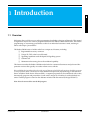
1.1 Overview
Welcome to the world of two-way radio programming from Radius a division of Motorola. This manual
is targeted for anyone who wants to program features into the Radius GM300 mobile radio. This feature
programming, or customizing, personalizes a radio for an individual customer's needs, resulting in
radios with unique “personalities.”
The Radius GM300 series of mobile radios has a unique set of features, including:
❏
❏
❏
❏
❏
Programmable accessory connector
Unique PL/DPL codes for each channel
Signalling capabilities with the RapidCall Signalling system
Channel scan
Maintenance-free tuning, due to the wideband capability
This feature set makes the Radius GM300 an ideal radio for commercial businesses and police and fire
protection services that typically use radios in their service vehicles.
How can Radius design radios with such a wide range of features and still offer radio servicers the ability to customize and personalize radios? The answer is in the modern microprocessor chip technology in the radio and
the use of Radius' Radio Service Software (RSS) - a computer program that, when interfaced with a radio,
electronically programs and personalizes a radio with a unique set of features for each individual customer. The RSS program is found on the diskettes included with this manual (Package HVN8177).
Note: No tools are needed to use the RSS program.
October, 1996
6880902Z36-B
1-1
Introduction
GM300 Radio Service Software Manual
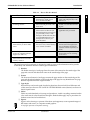
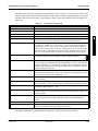
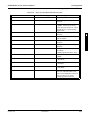
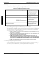
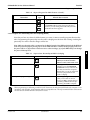
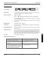
Prerequisites
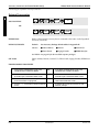
The following are some of the features and functions available when using the RSS program:
1
GM300 RSS Programmable Features
GM300 RSS Service Functions
Transmit (Tx) frequencies
Receive (Rx) frequencies
PL/DPL codes
Signalling system parameters*
Scan lists and scan options
Accessory connector definition*
Reference oscillator alignment
Transmit deviation alignment
Transmit power alignment
Replaced power amplifier calibration
Replaced logic board calibration
Replaced RF board calibration
(* 16 Channel Model only)
Figure 1-1.
RSS Programmable Features and Functions
This radio customizing and servicing is accomplished by using a standard IBM-XT/AT (or compatible),
IBM convertible, or System/2 Model 30/50/70 computer.
Note: Prior to purchasing a computer, we recommend you test any computer's RSS “compatibility” by
connecting all the hardware, installing the software, starting the RSS and reading and writing data to
and from a radio. If problems occur, call the phone number on the front cover for help.
1.2 Prerequisites
To use RSS and to program the radios, we recommend a basic working knowledge of the following:
❏
❏
❏
❏
❏
Microcomputers.
Microsoft Disk Operating System (MS-DOS), version 3.2 or later.
The radio's available features (see Feature Chart in Basic Features section),
The GM300 Study Guide, and the GM300 Operator's Manual.
Your customers' needs.
For computer beginners, we shall teach some computer and DOS basics. However, this manual is written
for both beginners and advanced users, so the primary prerequisite for using RSS is the desire to program
and deliver an excellent radio to your customer.
1.3 Using This Manual
This manual is designed to teach basic feature programming and to speed up access to technical reference
information. It is intended for both beginners and advanced users of computers and RSS. To speed up
access to the information, we've included key words in the page headers, numerous tables and lists, and
a revised Table of Contents and reference sections. To help you better understand the information presented, we've expanded the Getting Started section, Glossary and Abbreviation list, and added a Tutorials section to get new users started faster. The table below lists suggested ways to use this manual.
1-2
6880902Z36-B
October, 1996
GM300 Radio Service Software Manual
Introduction
Using This Manual
Table 1-1.
First Time User
How to Use this Manual
Occasional User
Frequent User
1. Read the Introduction section
1. Review Getting Started to set up
the hardware, install, start or
move around in the RSS
1. Decide what features you want
radio-wide and permode; write
them down
2. Read and do the steps in section
2, Getting Started
2. Decide what features you want
radio-wide and per-mode; write
them down.
2. Decide whether to start from
scratch or to clone from an existing file.
3. Do one or more of the tutorials.
3. To add more features to a radio,
either read in a archive file (see
the Cloning tutorial, in Section 3)
you previously saved, or redo
the steps in the first tutorial, then
for each additional feature, use
the Reference sections to program the feature
3. Use sections 1, 2, 3 and the
appendixes only as needed
4. Use the Glossary for terms and
abbreviations you don’t understand
4. For adding scan features, review
the Feature Chart, and use the Reference sections as needed
4. Find most of your information
from Sections 4 through 8 (Fanning or thumbing through the
reference sections may be all you
need.)
1
5. To install an RSS update, refer
back to Section 2. For servicing,
see Section 8.
5. Know the phone number of a frequent user or Radius technical
support (see Table 1-2)
6. Do another tutorial within 48
hours of the first one for better
memory retention
The page layout and type selection is designed to speed up access to the information and to provide
visual clarity and distinction between certain types of information.
❏
❏
❏
❏
❏
October, 1996
Headers
The header area (top) of each page shows the name of the manual on the inside edge of the
page and a section and subsection name on the outside edge of the page.
Footers
The footer area (bottom) of each page contains the page number on the outside edge of the
page and the manual number on the inside edge of the page for easy identification if a page
becomes separated from the original manual.
Type Styles
Keyboard keys and words typed from the keyboard are shown in bold font. RSS menu and
screen names are shown in ALL CAPITAL LETTERS RSS field names (features) are shown in
Initial Capital Letters.
Tables
Tables are used abundantly to list steps and procedures. A table is anything contained within
a box with vertical or horizontal lines through it. Shaded tables apply only to procedures for
diskette use and not for hard disk use.
Figures
Figures can be drawings or pictures of hardware and equipment, screen-captured images of
RSS menus and screens, or computer-created graphics.
A stop light represents an important warning.
6880902Z36-B
1-3
Introduction
GM300 Radio Service Software Manual
Subscription Information
1.4 Subscription Information
1
Your RSS is part of a subscription. We shall keep you advised of changes and automatically mail revisions
throughout the life of the subscription.
A subscription is good for one site. Under the terms of your subscription, you may install the RSS on as
many personal computers as desired at that one site. Another site location requires another subscription.
When contacting the Radius Distribution Center for your region of the world, you may need to reference
your subscription model number. See Table 1-2 below for your region and model number.
Table 1-2.
Region/Location
Subscription and Support Group Numbers.
Subscription
Model Number
Japan
U.S.
H5106
H5028
Canada
Australia
Europe
Germany
Rest of world
H5041
H5044
H5114
H5133
H5030
Support Group
Radius North America Distribution Center,
1-800-356-1520
Technical Hotline Center, 1-800-663-1771
Local Radius Dealer*
Local Radius Dealer*
Radius North America Distribution Center,
1-319-385-5395
* Your local dealer has access to Motorola technical help.
1-4
6880902Z36-B
October, 1996
2 Getting Started
2
2.1 Overview
In this section you will identify, install and learn to use the necessary hardware and software to run RSS.
You will become familiar with the computer, the keyboard, RSS menus, screens and fields. This section
prepares you for Section 3 - Tutorials, in which you will actually program a radio.
If you cannot complete this section at one time, we recommend you first set up the hardware (15 minutes). As time permits, continue with the remaining second-level subsections, finishing one second-level
subsection before allowing an interruption. Most of the second-level subsections can be read in 15 minutes. Actually starting RSS only takes a few minutes for a first-time user, but the exploration of the menus
and screens can vary from user to user.
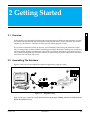
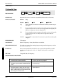
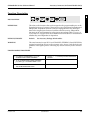
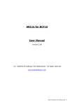
2.2 Assembling The Hardware
Figure 2-1 below shows the required and optional equipment to program a radio.
8
7
4
1
2
3
Figure 2-1.
9
5
6
Equipment Setup
Note: Items 2, 3, 4, 5 and 7 are in the “first-time start-up package” (H5040), which is available from the
Radius Distribution Center.
October, 1996
6880902Z36-B
2-1
Getting Started
GM300 Radio Service Software Manual
Assembling The Hardware
1.
Computer.
Recommend IBM-XT/AT or compatible, IBM convertible or IBM System/2 Model 30/50/70, with
640 K of RAM, and one diskette drive plus one hard
disk drive. Computer should run DOS 5.0. or
greater. See Hardware Platform - below.
2.
Cable.
Radius HKN9216. Radio Interface Box (RIB)-toIBM-AT cable. Has a 9-pin end and a 15-pin end.
2
3.
RIB.
Radius HLN9214. Radio Interface Box.
4.
RIB Power Supply.
Radius HSN9412.
(110 VAC) Using the power supply is more reliable
than using a weak battery. A 220 VAC wall supply
is available (01-80358A56).
(For laptop computer and on-the-road use only,
omit the RIB Power Supply and use 9V battery (not
included)).
Warning: LED remains lit with a weak battery - this
may cause certain errors on screen. Use a fresh 9V battery.
5.
Cable.
Radius HKN9217. RIB-to-Radio cable.
6.
Radio.
Radius GM300 Mobile Radio.
2-2
6880902Z36-B
October, 1996
GM300 Radio Service Software Manual
Getting Started
Assembling The Hardware
7.
Optional Adapter.
Radius HLN9390 XT- to-AT-computer cable
adapter.
8.
Radio Power Supply.
0 - 15 VDC, 15A. Set between 11 and 15 volts.
9.
Power Cable.
2
HKN4137AR, HKN9402A, HKN4137A.
Table 2-1.
Steps to Connect Hardware
1. Connect 1 and 3 with 2.
First plug the 9-pin end of B into the communications port of A. Then connect the 15-pin end to
C. (If your computer has an XT-style communications
port (25 pin connector), you will need the extra adapter
8 (HLN9390) to insert between 1 and 2.)
3. Plug 4 into an AC wall outlet,
and connect the other end to 3.
2. Connect 6 and 3 with 5.
The 25-pin end of 5 goes into 3, and the “modular
telephone” connector end plugs into the microphone jack on the front of 6.
4. Connect 6 to power supply 8 with 9.
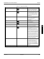
After you connect the hardware, turn on the radio by turning the volume control clockwise. You will hear
one of the following types of tones..
Table 2-2.
Hardware tones
This tone...
Means this...
Higher-pitched, short tone
Hardware is connected correctly, and the radio’s internal firmware is operating correctly.
High-pitched short tone followed by long (10 sec.)
low-pitched tone
Hardware is incorrectly connected (check connections), radio is not receiving enough power (radio
needs between 11 and 15 volts), or a checksum error is
present in the radio’s codeplug (call 1-800-356-1520
and report what you did and heard)
Continuous long, low tone
Critical failure - a radio’s internal software malfunction.
October, 1996
6880902Z36-B
2-3
Getting Started
GM300 Radio Service Software Manual
Hardware and Software Platform
You can install, start or explore RSS using just the diskettes and your computer if you don't have all the
hardware. You can even update existing radio archive files stored on disk. What you cannot do without
the hardware is read from or save to an actual radio.
When programming or calibrating a radio, DO NOT disconnect the radio from the RIB when the computer is communicating with the radio - it may leave the radio in an inoperable state. The only recommended time to disconnect the radio is at the MAIN MENU or GET/SAVE screens.
Note: If you are using a laptop computer (for example an IBM PC Convertible) and you plan to use the
RSS while the computer is in battery mode, you may need to set the serial/parallel adapter to run on battery power. This can be done with the application diskette supplied by the computer manufacturer. If this
is not done, you will receive serial bus errors.
2
Note: If your RIB has a switch and LED, be sure to turn on the switch before each programming session.
2.3 Hardware and Software Platform
2.3.1 Minimum Platform Requirements
We recommend the following minimum hardware/software platform:
❏
❏
❏
❏
❏
80286 Microprocessor
640 K of RAM
HDD (Hard Disk Drive) 30 Mb or higher
DOS 5.0 or higher
3.5 inch FDD (Floppy Disk Drive)
2.3.2 Recommended Buy
We recommend that as your computer systems are upgraded, they should meet the following minimum
standards:
❏
❏
❏
❏
❏
❏
❏
80386 Microprocessor
4Mb of RAM
HDD (Hard Disk Drive) 80 Mb or higher
DOS 5.0 or higher
1.44 Mb 3.5 inch FDD (Floppy Disk Drive)
Two (2) serial ports
Mouse or trackball
Purchasing an 80386 computer with the minimum configuration as detailed above will ensure that your
computer systems will not be quickly outdated.
2-4
6880902Z36-B
October, 1996
GM300 Radio Service Software Manual
Getting Started
Understanding Computer Basics
2.4 Understanding Computer Basics
If you are already familiar with computers, skip this section and proceed to Section 2.7 on page 2-19 Starting RSS.
Your computer can be compared to both a file cabinet and an electronics technician. A file cabinet provides easy handling, storage and retrieval of written data. So does a computer. The technician can, with
tools, manually and physically alter the radio's features and functionality. So does a computer with RSS.
A radio dealer can give a radio unique features, save those features for future reference, and service a
radio internally, all without opening a drawer, thumbing through papers, picking up a tool or disassembling the radio.
Let's learn some of the types of computers that can be used for programming radios, the major parts of a
computer, and the ways to store your desired radio personality data.
2.4.1 Which Computers Run RSS
RSS is designed to run on the following IBM computers and their compatibles and convertibles: IBM XT/
AT, and IBM System/2 Model 30/50/70 computers. If you wish to use a laptop computer, we recommend the Everex Tempo Carrier laptop.
October, 1996
6880902Z36-B
2-5
2
Getting Started
GM300 Radio Service Software Manual
Understanding Computer Basics
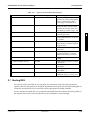
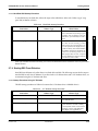
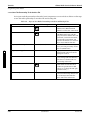
The following table lists computers with known compatibility problems:
Table 2-3.
Computers with Known Compatibility Problems
Computer Type
AT&T 6300 Plus
2
2-6
Problems
Recommendation
This is an AT clone with an XT bus.
Not recommended.
Bondwell
Compatibility problem.
Not recommended.
Compaq III 386/20
RSS won’t work when executed
from a diskette drive - causes a failure on the serial port.
Execute from hard drive only.
Compaq LTE
Error #5 with COM test
Not recommended.
Compaq Model 1605
I/O port pinouts are not compatible.
Not recommended.
Epson Equity 3
I/O port pinouts are not compatible.
Not recommended.
Epson Laptop Q150A
Power failure during COM test.
Not recommended.
Everex1800D
RSS won’t run for portables
External serial port solves problem.
IBM Model 50Z
Machine hardware problem
Replace mother board or add asynchronous COM card.
IBM Model 70
Machine hardware problem
Replace mother board or add asynchronous COM card.
Memorex
Unknown
Not recommended.
Sperry AT
Unknown
Not recommended.
Tandon TN7000
Clock rate/speed problems
Not recommended.
Tandy
Clock rate/speed problem.
4.7 MHz rate only works for mobile
applications.
Toshiba 1000
Unknown.
Not recommended.
Zenith Supersport 286
Chip problem
Not recommended. Zenith dealers
can fix. Newer versions may work.
6880902Z36-B
October, 1996
GM300 Radio Service Software Manual
Getting Started
Understanding Computer Basics
2.4.2 Identifying Major Computer Parts
Computers range in complexity and size from small laptops to large mainframes. Falling between this
range is the microcomputer. Most microcomputers consist of a monitor, a system unit, and a keyboard.
These components are:
1.
Monitor
Monitors perform like a window into the computer,
allowing you to see the data inside the computer.
Monitors come in a variety of sizes and colors.
Some can be bigger than a 19-inch diagonal television, though a common size is 12 inches diagonally.
2
Monochrome monitors have only one color behind the words and pictures on the display, which in
many cases is either green, amber, white or black. Color monitors can display two or more colors on
the display at a time, but with color monitors a slight decrease in picture sharpness or text legibility
may be experienced. Colors on the RSS screen can be selected or changed by the user by using the
RSS. To help users quickly find their place on the display before typing, a flashing underscore, called
a “cursor” serves as a visual place indicator.
Besides the display, a monitor has a power cord, an on/off switch, brightness and contrast dials, and
a cable connection to the system unit. The RSS can function with either monochrome, CGA, EGA or
VGA-based monitors.
2.
System Unit
The system unit contains a special chip that is the
“brain” of the computer, one or more diskette
drives, a hard-disk drive (if so equipped), a cable
connection to the keyboard, one or more communications ports and an on/off switch. System units
use an 8088, 8086, 80286, 80386 or 80486 chip with
speeds between 4.77 MHz and 50 MHz. The system
unit should be treated with care, as jarring and hot
temperatures could internally damage the unit.
Note: The RSS program may not function properly on computers with speeds greater than 20MHz.
3.
Keyboard
A user instructs the computer what to do by typing
commands on the keyboard. The monitor shows
the commands as they are typed. Most keyboards
have letter keys, numeric keys, and a number of
special keys that perform special functions.
Section 2.8.1 on page 2-26 - Keyboards and Their
Functions describes some of these special keys and
how they perform with RSS.
October, 1996
6880902Z36-B
2-7
Getting Started
GM300 Radio Service Software Manual
Understanding Computer Basics
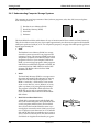
2.4.3 Understanding Computer Storage Systems
The computer can store large amounts of data (software programs, code, data, files) in several places.
Some of these places are:
❏
❏
❏
❏
Random-Access Memory (RAM)
Read-Only Memory (ROM)
Hard disk
Diskettes.
2K
2
The RAM, ROM, hard disks and diskettes all vary in function and all have certain size limits (memory).
They all store data in terms of bytes; a byte equals approximately one character as typed on the keyboard.
1,024 bytes equals one kilobyte, or 1K. For comparison purposes, one page of double-spaced, typed text
equals approximately 2K.
1.
RAM
The Random Access Memory (RAM) is a storage
area in the system unit used to run programs and
operating systems. The amount of RAM varies from
computer to computer, and it directly affects which
programs will run on your computer. With more
RAM, you can run larger programs. Most programs
indicate how much RAM is required to run RSS. We
recommend at least 2 MB of RAM to run the RSS
program. The Radius radios also have RAM
embedded in them.
2.
ROM
The Read Only Memory (ROM) is a storage area in
the system unit used by the computer for start-up
and Power-On Self-Test (POST) purposes. The
ROM is “read-only”, which means a user cannot
write or save data to it, over it, delete it, or in any
other way destroy it by using the keyboard keys.
The program in the ROM is hard-coded into the
ROM chip, and as such is protected from user
errors. The Radius radios also have ROM embedded in them.
3.
Hard Disk and Hard-Disk Drive
A hard disk is a storage area inside the hard disk
drive, both within the system unit. Hard disks store
a user's programs and files (data). The hard disk
drive accesses the hard disk data the same way a
record player accesses the music (data) on a record,
or a CD player accesses the music on a CD. Both the
disk and the disk drive are needed to store (write or
save) or retrieve (read) any data. The data stored on
a hard disk can originate from data the you gener-
2-8
6880902Z36-B
Inside unit
October, 1996
GM300 Radio Service Software Manual
Getting Started
Understanding Computer Basics
ate at the keyboard, or from data copied from a diskette. Hard disks can store from 20 megabytes (1
megabyte(MB) = 1 million characters) to over
100MB of data, depending on model type. Most
hard-disk drives are labelled as the “C” drive.
4.
Diskettes and Diskette Drive
Diskettes also store users' programs and files, but
are different from hard disks because of their transportable, small size and packaging. A diskette must
be “formatted” before storing your files and programs on it. After a diskette is inserted into a diskette drive, data on the magnetic diskette can be
retrieved, stored, manipulated or erased. The operation of the diskette drive is also similar to the
record-player concept described in the hard disk
subsection.
2
Diskettes come in two sizes: 3.5 inch and 5.25 inch. Each diskette size has two memory capacities - low
density and high density. The table below shows the memory capacity of both diskette size.
Table 2-4.
Diskette Size and Capacity
Size
Low Density
High Density
3.5 inch
720K
1.44MB
5.25 inch
360K
1.2MB
The RSS program is distributed to you on one 3.5" low density diskette and two 5.25" low density diskettes so that it may be easily loaded onto any appropriate computer, regardless of the type of diskette
drive that is available. Handle the diskettes carefully - avoid contact with the shiny, brown, magnetic disk
surface under the protective plastic cover on the 5.25" diskette and the magnetic disk surface under the
sliding metal plate on the 3.5" diskette. Such contact could damage the data and make it unreadable by
the drive.
Diskette drives come in two sizes; one to accommodate the 5.25" diskettes and one to accommodate the
3.5" diskettes. With the 5.25" diskette drives, after inserting a diskette as far as it will go, you must close or
push down the “drive door” located on the outside of the drive or else the computer will not read the
data on the diskette. This drive door generally swings down and locks into place when firmly pressed,
and it releases when gently pressed back the other direction when you want to remove your diskette.
With the 3.5" diskette drives, the diskette is inserted into the slot until it locks into place. The drive does
not have a door like the 5.25" drive. Instead it has an eject button, which when pressed firmly will release
the diskette.
Most diskette drives are labelled “A” or “B”, with “A” generally being the first (or highest) one. The
drives are sometimes labelled by the computer dealer before delivery to the customer.
Though it requires more steps, it is possible to run the RSS with only one diskette drive and no hard
drive. Most businesses today have computers equipped with at least two drives, whether they are a hard
drive and a diskette drive or two diskette drives. Instructions, steps, tables and procedures that apply to
computers with only diskette drives (no hard disk drive) will be displayed in a shaded box.
October, 1996
6880902Z36-B
2-9
Getting Started
GM300 Radio Service Software Manual
Understanding Computer Basics
To learn more about computer basics, read “The Personal Computer Book” by Peter McWilliams, Prelude
Press, Los Angeles, CA. Call 1-800-LIFE-101 to order or secure further information.
2.4.4 Understanding the Disk Operating System (DOS)
A computer user operates, communicates with and commands the computer using the computer's Disk
Operating System (DOS). DOS commands have special meanings to the computer.
Before you can use DOS commands, they must be either installed on your hard disk, or loaded into the
computer's RAM via your diskette drive. The table below lists the procedure to “Load DOS” if your computer does not have a hard disk. This table assumes your computer has a diskette drive labelled A.
2
Table 2-5.
Loading DOS From a Diskette
Instruction
How to Do It/What it Means
1. Insert DOS diskette into drive A
Put DOS diskette into the slot on the diskette
drive and insert it as far as it will go. Close the
drive door
2. Power up the computer
Power up the monitor, then the system unit.
The computer will read the data on the diskette and load DOS into the computer’s temporary storage - RAM. The computer’s prompt
will be: A
3. Remove DOS diskette
Open the drive door and remove the DOS diskette.
DOS version 3.2 or later is required to run RSS. However, we highly recommend later versions, the later
the better, such as DOS 5.0.
Note: An intermittent serial bus error may occur when using DOS 4.01 - if after checking the communications between the computer and the radio you receive the same error, try a different DOS version.
DOS commands can be either upper case or lower case letters, it doesn't matter, but we show all DOS
command in upper case letters.
2-10
6880902Z36-B
October, 1996
GM300 Radio Service Software Manual
Getting Started
Understanding Computer Basics
The table below lists some of the DOS commands that you may use now or in the future for RSS work.
Words in italics mean you should substitute that word for the word that is appropriate for your specific
situation (such as your file's name or your directory name). After each command, press the Return (or
Enter) key.
Table 2-6.
Common DOS Commands
DOS Command
What it Means
A:
Go to drive “A”.
B:
Go to drive “B”.
C:
Go to drive “C”
CD\
Return to the root directory. CHDIR also works.
CD DIRNAME
Change directory to the directory named DIRNAME, maximum directory length is
8 characters. CD used alone will display the current working path name.
COPY B:*.* A:
Makes an identical copy of all files from root directory of diskette in “B” drive to
root directory of diskette in “A” drive. The *.* means all files within the directory
specified. You can also copy files in the same directory giving the file a different
name as the second argument to the copy command, and you can combine several
files into one file or append files. In all cases, the first argument is the source file
(the one to copy from) and the last argument is the target file (the one to copy to).
DEL *.*
Delete all files in current directory. WARNING: files cannot be recovered after executing this command without backups located in a different directory!
DIR
Lists the files in the current working directory. You can list files in other directories
too by specifying a pathname following the command. If you have more files than
will fit on the display, you can type DIR /P, which will make DOS pause when the
display is full. Pressing any key resumes the listing. DIR /W specifies a wide display (5 columns) of file names.
DISKCOPY B: A:
Copies the contents of the disk in drive B to the disk in drive A. Drives must be of
the same size and density. If your drives are not the same size and density, use the
same drive name twice, such as DISKCOPY A: A:.
FORMAT A:
Format an unused, new or old diskette in drive “A” of the computer so it will
accept DOS files.
MD DIRNAME
Make a new sub-directory called DIRNAME of 8 characters or less. (You substitute
your own directory name for the italicized word DIRNAME.) MKDIR also works.
PROMPT $P$G
Change the display’s prompt to include the current working directory’s drive and
path name, followed by the “>” sign.
PATH
Set a command search path (such as PATH=C:\MRSS\GM300\ARCHIVE). This
tells the computer to search this directory after the working directory when a command is entered.
RD DIRNAME
Remove a sub-directory called DIRNAME. Removal of the sub-directory requires
that it be empty. Files can be deleted by the DOS DEL command. RMDIR also
works.
VER
Prints the DOS version installed on the computer, such as “DOS Version 5.0”.
XCOPY
Copies files and directories, including all sub-directories. This command uses disk
space more efficiently and can speed up file access time.
For further information on these and other commands, consult your DOS User's Manual.
October, 1996
6880902Z36-B
2-11
2
Getting Started
GM300 Radio Service Software Manual
Understanding Computer Basics
You may have noticed some special characters in the preceding table (*, $, .). Certain keyboard characters
mean special things to DOS. Some of these are:
Table 2-7.
DOS Special Characters
DOS Special Character
What It Means
*
Wildcard character. You can substitute this character for any type or
quantities of characters/digits that
follow (not precede) it
\
Backslash. A special character to
separate directories when specifying path names. By itself, it also represents the root directory
?
Wildcard character meaning you
can substitute/match it for any single-digit or character
$P$G
Sets the display’s default prompt to
be the current drive and path name,
followed by the “>” character
.
Period (or “dot”). This character,
though not visible when a DIR
command is executed, separates
DOS file names from their extensions. Remember this when copying or deleting files.
2
There are a couple limitations you may want to know about DOS, RSS files and directories.
❏
❏
❏
DOS only allows file names to be 8 characters long. However, file names can have an optional
1, 2 or 3-character extension after the file name. The extension must be separated from the file
name by a period (sometimes called a “dot”).
DOS allows only 111 files under the root directory (topmost) on any diskette or hard disk. We
highly recommend that you further subdivide your files into more directories before you
accumulate this many files in any directory, not just the root directory. It's very confusing and
time-consuming to work with or view this many files at once.
The maximum number of files allowed by RSS in any non-root directory, whether diskette or
hard disk, is approximately 400. This is an RSS limitation, not a DOS or computer limitation. If
you have more than 400 files, create another directory.
2.4.5 Using RSS with Window Applications
The RSS is not a Microsoft Windows program. The RSS program can be executed only from the DOS
prompt on computers which are running Microsoft Windows.
2-12
6880902Z36-B
October, 1996
GM300 Radio Service Software Manual
Getting Started
RSS Diskettes Contents
2.5 RSS Diskettes Contents
Table 2-8 and Table 2-9 on page 2-14 list the files located in the diskettes you received with this manual.
Table 2-8.
RSS Diskette Contents - ROOT DIRECTORY
File Name
HDINSTAL.EXE
File Type
installation
Description
Installs RSS on the hard disk. To
install RSS on your hard disk from
3.5" diskettes, type:
HDINSTAL C: 3.5
2
To install RSS on your hard disk
from 5.25" diskettes, type:
HDINSTAL C: 5.25
HDINSTAL accepts three parameters, the first is the targeted installation drive letter, the second is an
optional installation pathname, and
the third is the disk size of 3.5 or
5.25 (5.25 is the default)
GM300.EXE
executable file
Runs the RSS. If using 5.25” diskettes, insert diskette #1. To start
the RSS, type:
GM300_1.OVL
executable overlay file
Part of the RSS after the .EXE file starts
GM300_2.OVL
executable overlay file
Part of the RSS after the .EXE file starts
GM300_3.OVL
executable overlay file
Part of the RSS after the .EXE file starts
GM300_4.OVL
executable overlay file
Part of the RSS after the .EXE file starts
GM300_5.OVL
executable overlay file
Part of the RSS after the .EXE file starts
GM300_6.OVL
executable overlay file
Part of the RSS after the .EXE file starts
GM300_7.OVL
executable overlay file
Part of the RSS after the .EXE file starts
GM300_8.OVL
executable overlay file
Part of the RSS after the .EXE file starts
GM300_9.OVL
executable overlay file
Part of the RSS after the .EXE file starts
GM300_10.OVL
executable overlay file
Part of the RSS after the .EXE file starts
GM300_11.OVL
executable overlay file
Part of the RSS after the .EXE file starts
GM300_12.OVL
executable overlay file
Part of the RSS after the .EXE file starts
GM300.CFG
diskette configuration data
Default computer configuration data
for running the RSS off the diskette
GM300.MDF
definition file
Data file used by RSS
GM300._HD
hard disk configuration data
Default computer configuration data
for the hard disk. The installation must
be executed to have this file correctly
initialized
GM300.HLP
help
Contains on-line help for the RSS,
accessed via the RSS
GM300
October, 1996
6880902Z36-B
2-13
Getting Started
GM300 Radio Service Software Manual
RSS Diskettes Contents
Table 2-9.
RSS Diskette Contents - ON DEMO Diskette (Not Copied by HDINSTAL command)
File Name
2
File Type
Description
DEMO1.BAT
demo/tutorial file
Starts up the on-line demonstration
of how to program a radio. The
demo will start when you type:
DEMO1
DEMOTRAY.001
demo slide tray file
Lists the order of the picture slides
PRESENTS.COM
presentation software
Public domain software that presents the demo outlined in the demo
slide tray file
PIC
picture slides
These are the demo slides used in
the presentation
A9999999.999
archive file
An image of a radio’s personality
(codeplug). Archive files always
start with an “A”. The rest of the file
name (italic 9’s) is the radio’s serial
number. It is created
GM300.DBF
archive database header file
Created by RSS the first time an
archive directory path is specified.
Helps RSS locate/retrieve archive
files
A “file” can be a program (a set of commands to tell the computer what to do), or a collection of data or
information. As mentioned in the DOS section, DOS files generally have two parts - a file name followed
by an optional file extension. The extension provides an easy way to, at a glance, identify or tag files for
easy grouping or categorizing. In the computer world, some file extension naming conventions have
evolved, and Radius uses these conventions in RSS.
The “A” in the file name “A9999999.999” in Table 2-9 indicates that the file being saved is a radio
“Archive” file. The “9999999.999” refers to the radio's 10-digit serial number. As DOS file names are limited to 8 characters in the prefix and 3 characters in the extension, this RSS default radio archive file naming system conforms correctly. For example, the sample file name “A1234567.890” could be a valid radio
archive file name.
The RSS also creates files. These files are:
❏
❏
❏
❏
GM300.DBF - An archive data base header file created on the hard disk after RSS is started,
and also created on the diskette if you save archive files to a diskette. It allows the RSS to
locate and retrieve archive files.
GM300.BAT - A file generated by the hardware installation command (HDINSTAL) and
located under the root directory of the hard drive, enabling RSS to startup from the root directory.
Archive files - Computer files of the radio personalities stored on the hard disk or a diskette.
Backup files - Extra copies of the archive files stored on a different diskette and/or drive than
the original archive files.
Next you'll learn how to organize your own disk and diskettes that you'll use to store your radio archive
files. We suggest that frequent RSS users and computer pros skip Organizing Your Disk and Diskettes
and go directly to Starting RSS. New users should read all sections.
2-14
6880902Z36-B
October, 1996
GM300 Radio Service Software Manual
Getting Started
Organizing Your Disk and Diskettes
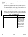
2.6 Organizing Your Disk and Diskettes
When you first start using computers you typically do not have many files to organize. But after a while
it gets increasingly difficult to distinguish between file types, to pick out a specific file in a long list, to
keep track of what's in which file, or to remember which files are similar in content. Therefore, it's important to spend some time now deciding which types or groups of files should be located together in a common place, called a directory.
You can make directories using the DOS MD or MKDIR commands (or inside RSS via the FILE MAINTENANCE MENU).
You may want to organize your directories first by customer area, then by customer name, and finally by
radio model type, or perhaps in the reverse order. Consider the different ways in which you operate your
business - do you separate radio files by customer location, by sales revenue, by fiscal year, or perhaps by
date of purchase? When deciding how to organize your files and directories, we offer a few suggestions.
❏
❏
❏
❏
October, 1996
Put as few directories as possible near the top, or root, of your directory tree, considering your
future growth too. (For example, if you have 100 customers within 4 geographical areas, we
suggest your first level of “sub” directories be the areas that encompass the customer. The next
level of directories would be the customer names within each of those areas.) The idea is to
make the root system spread out wider the deeper you grow, similar to a pyramid shape.
Keep the RSS diskette contents in one directory and your archive files in a different directory.
Keep archive files in separate directories according to radio model type (GM300, GP300, etc.).
It is not possible to know a file's model type by looking at the file name. Have a separate directory name for each radio model, then store the archive files for that specific model within the
appropriate model directory. This way archive files for multiple model types are not located in
the same directory.
Dedicate and create a separate diskette for your backup files, and always make backup copies
of your files. If you routinely store archive files on your hard disk, make backup copies of your
files on a diskette. This is very easy to do using the RSS, and is explained in Table 2-12 on
page 2-20. If you don't have a hard disk, you can use the DOS diskcopy command to make a
backup copy of your archive files. This command is discussed in Table 2-5 on page 2-10
6880902Z36-B
2-15
2
Getting Started
GM300 Radio Service Software Manual
Organizing Your Disk and Diskettes
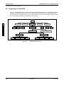
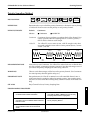
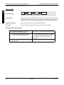
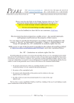
2.6.1 Organizing Your Hard Disk
Figure 2-2 is a sample directory tree for storing your radio archive files on your computer’s hard disk.
Though your hard disk directory tree may be a little different based upon your way of doing business,
this setup may be a starting point for you. To create this directory tree on your hard disk, follow the steps
below. After each command, press the Return (or Enter) key.
root
2
Spread Sheet
etc...
P100
WP
MRSS
Data Base
GM300
P200
GP300
1991
SECURITY
etc...
1992
TOWING
COURIER
Figure 2-2.
2-16
M500
executable program files
ARCHIVE
FIRE
Graphics
FIRE
SECURITY
TOWING
COURIER
Hard Disk Directory Tree
6880902Z36-B
October, 1996
GM300 Radio Service Software Manual
Getting Started
Organizing Your Disk and Diskettes
Table 2-10.
Steps to Create Hard Disk Directory Tree
Instruction
What To Type
Explanation
1. Go to drive C
C:
Go to Drive C
2. Go to root directory
CD\
Move (change directory) to the root
directory
3. Make MRSS directory
MD MRSS
Make a directory under root called
“MRSS”. You may have several
other directories under root, such as
spread sheet or word processing
applications
4. Go to MRSS directory
CD MRSS
Change directory to the MRSS
directory
5. Make GM300 directory
MD GM300
Make a directory under MRSS
called “GM300”
6. Go to GM300 directory
CD GM300
Change directory to the GM300
directory
7. Make ARCHIVE directory
CD ARCHIVE
Change directory to the ARCHIVE
directory
8. Make 1992 directory
MD 1992
Make a directory under here (at
C:\MRSS\
GM300\ARCHIVE) called “1992”.
9. Make FIRE directory
MD 1992\FIRE
Make a directory under 1992 called
“FIRE”
10.Make SECURITY directory
MD 1992\SECURITY
Make a directory under 1992 called
“SECURITY
11. Make TOWING directory
MD 1992\TOWING
Make a directory under 1992 called
“TOWING”
12.Make COURIER directory
MD 1992\COURIER
Make a directory under 1992 called
“COURIER”
13.Make 1991 directory
MD 1991
OPTIONAL - Repeat steps 7-11 for
the 1991, FIRE, SECURITY, TOWING and COURIER directories (for
the year 1991) if you want to
arrange past files in this way.
October, 1996
6880902Z36-B
2
2-17
Getting Started
GM300 Radio Service Software Manual
Organizing Your Disk and Diskettes
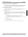
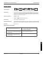
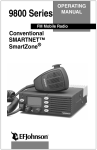
2.6.2 Organizing Your Archive File Diskettes
Figure 2-3 below shows a sample directory tree for storing your radio archive files on a diskette.
root
FIRE
2
SECURITY
Figure 2-3.
TOWING
COURIER
Diskette Directory Tree
Organizing a diskette is easier simply due to the limited space on a diskette. Though your tree may be
different based upon your way of doing business, this set-up may be a starting point for you. Be sure to
label the outside of your diskettes accurately, such as “1992 GM300 Archive Files.” Depending on the size
of your business, you may even have a separate diskette for FIRE, one for SECURITY, etc.
To create the directory tree shown in Figure 2-3 on your diskette, follow the steps listed in Table 2-11 on
page 2-19. After each command, press Tab (or Return or Enter). This exercise assumes you are using drive
A and the diskette contains only GM300 archive files (not RSS files and not backup files).
2-18
6880902Z36-B
October, 1996
GM300 Radio Service Software Manual
Getting Started
Starting RSS
Table 2-11.
Steps to Create Diskette Directory Tree
Instruction
What to Type
Explanation
1. Create diskette label
Label formatted diskette to correspond to the contents of the diskette
such as “GM300 Archive Files”.
Don’t apply it to the diskette yet.
2. If no hard disk, load DOS
See Table 2-5 on page 2-10 to load
DOS using drive A. Remove DOS
diskettes after loading. If not at the
root directory of drive A, type: CD
3. Put new diskette in A
Insert a new diskette into drive A.
Close the drive door.
4. Format diskette
FORMAT A:
5. Label diskette
Remove formatted diskette; apply
label without covering the exposed
magnetic areas.
6. Insert diskette again
Insert diskette into drive A again.
Close door.
7. Start at root
CD\
Move (change directory) to the root
(uppermost) directory of the diskette.Omit if already at root level.
8. Make FIRE directory
MD FIRE
Make a directory under root called
“FIRE”.
9. Make SECURITY directory
MD FIRE
Make a directory under root called
“SECURITY”.
10.Make TOWING directory
MD TOWING
Make a directory under root called
“TOWING”.
11. Make COURIER directory
MD COURIER
Make a directory under root called
“COURIER”.
12.Create other directories
2
Format the new diskette in drive A.
Discard diskette if errors occur and
try another.
Make more directories for each
additional category you may need.
2.7 Starting RSS
You are now ready to start RSS on your computer. This subsection, which takes about 30 minutes,
explains when to install, reinstall or discard the RSS diskettes, then guides you through installing RSS on
a hard disk, and finally lists how to start RSS with the appropriate executable command.
If your computer has a hard disk, we recommend running RSS from the hard disk whenever possible, as
the response time with it is faster and the files are less susceptible to external damage.
October, 1996
6880902Z36-B
2-19
Getting Started
GM300 Radio Service Software Manual
Starting RSS
2.7.1 Making Backup Copies of RSS Diskettes
As with any program, it's important to make a backup copy of the RSS diskette before you begin to use it.
Whenever you receive a new version of RSS, you should make a backup copy.
If your computer has both 3.5" and 5.25" diskette drives, use one size diskette you received from us as
your working copy and the other size for your backup copy. Both sizes we deliver contain the exact same
files. If one becomes damaged, immediately make a working copy from the backup one.
If your computer has only one size diskette drive, the other size diskette(s) will be useless to you. For
example, if you have only a 5.25" diskette drive, the 3.5" diskette will not work in your drive. In this case,
make a backup copy of the 5.25" diskettes.
2
We recommend making a backup copy of the RSS diskette whose size matches your computer's diskette
drive, even if you have a hard disk. To make a backup copy, follow the steps in Table 2-11 on page 2-19.
These steps assume you have one diskette drive named A or you have two diskette drives that are not the
same size and density, and that DOS is loaded. (DISKCOPY will not copy from one drive to another if the
drives are not the exact same size and density.)
Table 2-12.
Instruction
Steps to Backup the RSS Diskettes
What to Type
1. Insert RSS diskette
2. Make the backup copy
Put supplied RSS diskette into drive
A; close the door.
DISKCOPY A: A:
3. Keep originals safe
2-20
Explanation
This copies the data on the source
diskette in drive A (supplied RSS
diskette) to the target diskette (the
newly-formatted diskette). Careful
- accidentally reversing the insertion
order of the diskettes will erase the
contents of the RSS diskette. DOS
will tell you when to insert the
source diskette (RSS one) and when
to insert the target diskette (the
newly-formatted one). When the
diskcopy is complete, use the target
diskette as the new working copy.
(If you have 5.25” diskette drives,
do another diskcopy for the second
diskette).
Store the original RSS diskettes in a
safe place - away from magnets,
moisture, heat and where they
won’t be bent.
6880902Z36-B
October, 1996
GM300 Radio Service Software Manual
Getting Started
Starting RSS
2.7.2 What to Do with Previous Versions of RSS Diskettes
After you make a backup copy of the new RSS diskettes, you may wonder what to do with the old, previous RSS versions you may have accumulated. We recommend discarding them so you always have the
most current version available and you won't mistakenly program a radio with outdated data.
2.7.3 Starting RSS From Hard Disk
To run RSS from the hard disk, it must first be installed there. A hard-disk drive installation program is in
the RSS diskettes. After installing RSS on your hard disk, follow the startup procedure.
2
2.7.3.1 Installing RSS on Hard Disk
Install the latest RSS version as soon as you receive it - using the install program with the diskettes you
received with this manual insures you have the latest and greatest version of the RSS. It also keeps important files in a consistent place for cross-referencing and future use. The software installation takes approximately three minutes.
The install program will:
❏
❏
❏
Create the MRSS, GM300 and ARCHIVE directories, if they are not already there.
Write over the old version's program files with the same name, if present.
Create certain files on the hard disk to make using the RSS easier (“.CFG”, “.DBF”, “.MDF”).
The install program will not:
❏
❏
Write over your archive files.
Write over your backup files.
Before doing the installation steps that follow, be sure you have made a backup copy of the RSS.
October, 1996
6880902Z36-B
2-21
Getting Started
GM300 Radio Service Software Manual
Starting RSS
The steps shown in Table 2-13 install RSS on a computer equipped with a hard-disk drive and two diskette drives. After each “What to type” step below, press Return or Enter.
Table 2-13.
Instruction
RSS Hard Disk Installation Procedure
What to Type
1. Put RSS diskette in drive A
Explanation
Insert the RSS diskette into drive A
(close the door). If you must use the
5.25” RSS diskettes, insert RSS diskette # 1 first. Later you will be
instructed to insert the other one
2. Go to drive A
A:
This tells the computer to work
from drive A.
3. Start the installation.
If installing from 3.5” diskettes type:
This transfers the RSS program to
your hard disk. Follow directions
and answer questions on the display when they appear.
2
HDINSTAL C: 3.5
If installing from 5.25” diskettes type:
HDINSTAL C: 5.25
4. Store diskettes in safe place.
When the DOS prompt returns, you
may start the RSS program.
Keep the RSS diskettes in a safe
place and start RSS from the hard
disk from now on.
Note: The RSS program takes up less than 1MB of storage on your hard disk.
After installing RSS on a hard disk, you may notice a .BAT, extension, a .CFG extension, a .DBF extension
and a .MDF extension on some files. These types of files are explained briefly below. Do not delete or
move these files from the C:\MRSS\GM300 directory.
❏
❏
❏
❏
“.BAT” A batch file. The HDINSTAL command file creates a file called GM300.BAT in the top
level directory of the hard drive.
“.CFG “Created and modified by the RSS, the configuration file (“.CFG”) contains the PC port
choice, default pathnames and the display-type data.
“.DBF” Created by the RSS the first time an archive file directory path is specified. This
archive database header file allows the RSS to locate and retrieve archive files, based on serial
numbers. DO NOT OVERWRITE OR DELETE THIS FILE. If you do, contact Radius Product Services.
“.MDF” The model definition file defines which radio models the RSS can program.
2.7.3.2 Installing on Multiple Computers or Networks
You may install RSS on several personal computers and laptop computers at a single site, according to
your license. If you have additional sites, you should purchase additional subscriptions.
2-22
6880902Z36-B
October, 1996
GM300 Radio Service Software Manual
Getting Started
Starting RSS
2.7.3.3 Hard Disk RSS Startup Procedure
To start RSS from your hard disk, follow the steps in the table below. After each “What to type” step,
press Tab (or Return or Enter).
Table 2-14.
Hard Disk Startup Procedure
Instruction
1. Move to C drive
2. Start the RSS program
How To Do It
What It Does
What to Type
C:
Work from hard disk, the C drive. If you
have a hard disk and you bring up your
computer with no diskettes in the diskette drives, you will already be at the C
drive.
GM300
2
This command starts the RSS program.
If it does not start correctly, you may
hear a tone or see an error message or error code printed on the display (see Appendix A and B). (This command makes
the MRSS, GM300 and ARCHIVE directories if not already present.) If the
RSS program does not start, verify that
the file GM300.BAT appears under the
root directory of the C drive
After you start RSS from the hard disk, you will see the BANNER screen. Hard disk users can proceed to
Banner Screen.
2.7.4 Starting RSS From Diskettes
Start RSS from diskettes only when there is no hard disk available. The following sections list the steps to
start the RSS for each size of diskettes. If you have both a 3.5" diskette drive and a 5.25" diskette drive, we
recommend using the 3.5" diskette and drive.
2.7.4.1 Startup Procedure Using 3.5" Diskette
The RSS startup procedure in Table 2-15 assumes the 3.5" diskette drive is labelled drive A.
Table 2-15.
Instruction
3.5" Diskette Startup Procedure
What to Type
1. Insert diskette
How to do it/
What to Type
Insert the 3.5” diskette into drive A
2. Move to drive A
A:
Direct computer to work from your
3.5” diskette drive
3. Start the RSS program
GM300
This command starts the RSS program. If it does not start correctly,
you may hear a tone or see an error
message or error code printed on
the display (see Appendix A)
October, 1996
6880902Z36-B
2-23
Getting Started
GM300 Radio Service Software Manual
Starting RSS
When you start RSS for the first time from a 3.5" diskette, you will see the following:
❏
❏
❏
SERVICE SOFTWARE CONFIGURATION MENU. (Press the F10 key to exit it for now, we'll
return to it later.) This menu will not appear subsequent times.
BANNER screen.
MAIN MENU.
2.7.4.2 Startup Procedure Using 5.25" Diskettes
The RSS startup procedure in the table below assumes the 5.25" diskette drive is labelled “A.”
When you start RSS from a 5.25" diskette, you will see the screens below in the following order:
2
❏
❏
❏
SERVICE SOFTWARE CONFIGURATION MENU.
BANNER screen.
MAIN MENU.
To prevent the SERVICE SOFTWARE CONFIGURATION MENU from appearing every time you start
RSS, see the specific instructions for 5.25" diskette use in “Setting Default Archive and Backup Paths” on
page 2-36.
2-24
6880902Z36-B
October, 1996
GM300 Radio Service Software Manual
Getting Started
Starting RSS
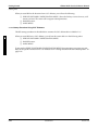
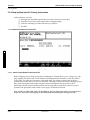
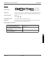
2.7.4.3 Service Software Configuration Menu
If you are using diskettes to run RSS for the first time, you will see the SERVICE SOFTWARE CONFIGURATION MENU (see below):
2
Figure 2-4.
Service Software Configuration Menu
For now, press the F10 key on your keyboard to exit this menu. We will return to it later.
2.7.4.4 Banner Screen
When the program correctly loads, you will see a “BANNER” screen (see below) with the Motorola logo
and copyright information.
Radius GM300/GR300/M120/M10
VERSION Rxx.xx.xx
DD-MMM-YY
Press Any Key To Continue
(C) Copyright MOTOROLA Inc.
Figure 2-5.
All Rights Reserved.
Banner Screen
Press any key. You will now see the MAIN MENU.
October, 1996
6880902Z36-B
2-25
Getting Started
GM300 Radio Service Software Manual
Navigating Through RSS Menus
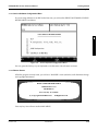
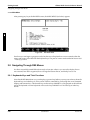
2.7.4.5 Main Menu
After pressing any key at the BANNER screen, the MAIN MENU (see below) appears.
2
Figure 2-6.
The Main Menu
From here you can begin to program a radio, but first we will explain how to move around within the
menus and screens of the RSS with the keyboard keys. The parts of a menu are described in Section 2.8.2
- Anatomy of a Menu.
2.8 Navigating Through RSS Menus
You have successfully started RSS and are ready to learn just what it is you see on the display, how to
move around, how RSS is organized, how to change the feature choices, and finally, how to exit.
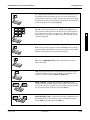
2.8.1 Keyboards Keys and Their Functions
Now that the RSS Main Menu is on your display, to proceed any further you may want to know about the
keyboard keys and what they do. Every action of RSS is controlled by you through the use of formatted
displays and function keys. The function keys are the ten keys labelled F1 to F10 grouped on the left hand
side of the keyboard on some keyboards or the twelve keys labelled F1 to F12 at the top of other keyboards.
2-26
6880902Z36-B
October, 1996
GM300 Radio Service Software Manual
Getting Started
Navigating Through RSS Menus
F1 - Displays help information on every screen and menu. This online help provides information on how to use the currently displayed menu, screen, line or field. You may also find system setup
information. In many cases the help is provided for the specific line
of the screen that is currently highlighted.
F1
F2
F3
F4
F5
F6
F7
F8
F9
F10
F2 - F9 - Perform special functions. The F2 through F9 keys perform specific functions and actions which can vary from menu to
menu and screen to screen. On some screens, F5 will print the current screen to your printer, and F8 will save the data and options
currently displayed.
2
F10 - Exit to previous menu or screen. The F10 key moves the display backward in the RSS tree, one screen or menu at a time. F10
performs this function on every menu and screen.
Esc
Esc - Exit to MAIN MENU. Esc performs this function on every
menu and screen.
Tab - Accepts data currently in field then moves prompt forward
one field. If a field’s entry is not accepted, an “error beep” will
sound. Performs exactly like Enter or Return key.
Tab
Enter
Shift
October, 1996
or
✚
Return
Tab
Enter or Return - Accepts data currently in field then moves
prompt forward one field. If entry is not accepted, an “error beep”
will sound. This key is usually two to four times as big as the letter
keys on the keyboard. Performs exactly like Tab key.
Back Tab (Shift + Tab) - Accepts data currently in field then moves
the prompt backward one field at a time. To backtab, press and
hold a Shift key and then press the Tab key.
6880902Z36-B
2-27
Getting Started
GM300 Radio Service Software Manual
Navigating Through RSS Menus
←
Left Arrow moves cursor left one character. The Backspace key
will also move the cursor backwards (left) one space at a time. Num
Lock (a keyboard key) must be turned off.
→
Right Arrow moves cursor right one space. Num Lock (a keyboard
key) must be turned off.
2
↑
Up Arrow - Scrolls through selections, or increases the current relative value. Num Lock (a keyboard key) must be turned off.
↓
Back
Space
or
Down Arrow - Scrolls through selections, or decreases the current
relative value. Num Lock (a keyboard key) must be turned off.
←
Back Space - Erases the current character in the field and moves
cursor one space backward (left). The back space key on some keyboards is a left arrow. Num Lock (a keyboard key) must be turned
off.
Del
Del - Erases current character in field.
PgUp
PgUp - Displays the previous page of information on the screen.
This is on the numeric keypad, generally found on the right side of
the keyboard. NUM LOCK (a keyboard key) must be turned off.
PgDn
2-28
PgDn - Displays the next page of information on the screen. This is
on the numeric keypad, generally found on the right side of a keyboard. NUM LOCK (a keyboard key) must be turned off.
6880902Z36-B
October, 1996
GM300 Radio Service Software Manual
Getting Started
Navigating Through RSS Menus
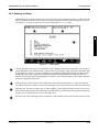
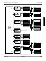
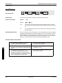
2.8.2 Anatomy of a Menu
Within RSS, there are menus that take you to screens where you can change the choice or value of a field.
The only difference between a menu and a screen is the information shown in the working area, shown as
3 in Figure 2-7. A menu or screen has four areas, labelled below as 1, 2, 3, and 4.
2
1
2
3
4
Figure 2-7.
An RSS Menu
1
Location ID Area. In this area you will find the words “Motorola Radio Service Software” and a menu or
screen pathname for the current menu or screen shown on the display. Each menu and screen name will
be separated by a colon (:). For some examples of this pathname, glance ahead in this manual to see the
menus and screens that are deeper into the RSS tree (past this MAIN MENU (the highest root level),
which is the assumed, default starting point). If a radio is connected, the current radio model being read
will also be displayed in this area.
2
Instruction Area. This area tells you the allowable actions for the current menu or screen. It is divided
into 4 lines; the first two lines are reserved for messages to the user, and the last two lines are status lines.
3
Working Area. This area of a menu (not a screen) displays a list of functions (menu choices) you can execute from the current menu. Each menu-item is preceded by an F-number key. Pressing an F-number key
advances you to another menu or screen (see Figure 2-9).
4
F-Key ID Area. This area displays the F-number keys and function names for the current menu or screen.
October, 1996
6880902Z36-B
2-29
Getting Started
GM300 Radio Service Software Manual
Navigating Through RSS Menus
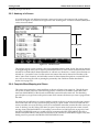
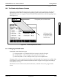
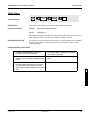
2.8.3 Anatomy of a Screen
As stated before, the only difference between a menu and a screen is the contents of the working area,
shown as 3 in Figure 2-7, and shown in Figure 2-8 as the “Working area”. Screens list features (fields) that
can be viewed or edited.
2
Working area
Figure 2-8.
An RSS Screen
The working area of a screen contains a list of programmable features called “fields” that can be selected
or changed using the arrow, tab or return keys described earlier. On some screens are features that can be
selected for each individual channel (hereafter we will refer to a channel as a “mode”); these features are
selected on a “per-mode” basis. On other screens are features that can be selected for all modes of the
radio (“radio-wide” features). And still other screens list those features that perform a certain RSS function, such as servicing the radio or printing the personality data. Fields are further described in
Section 2.9 on page 2-33.
2.8.4 Complete Menu Mapping at a Glance
The screens are organized in a tree-root fashion as shown in Figure 2-9 on page 2-31. Though this treeroot system is shown sideways in the following picture, it shows how the whole system starts with a
main root (MAIN MENU) at the left side and branches outward from the main root. This branching
grows deeper as you get closer to the precise screen which contains the feature you want to program into
the radio.
Traveling from one RSS menu or screen to another is similar to the way a car must use the road system to
drive to the other side of a lake, instead of flying directly as a plane would. To move forward from one
screen to another, use one of the F-keys until you've reached the menu that contains the other screen you
want. To back up, use the F10 key. Each time you press F10 you retreat to the previous screen or menu,
moving closer to the MAIN MENU. For example, to move from A to B in Figure 2-9 on page 2-31, from
the READ CODEPLUG screen you would press F10 to retreat to the GET/SAVE MENU, then F10 to
retreat to the MAIN MENU, then press F4 to advance to the CHANGE/VIEW MENU (Figure 2-10), then
finally press F5 to proceed to the MODE CONFIGURATION screen.
2-30
6880902Z36-B
October, 1996
GM300 Radio Service Software Manual
Getting Started
Navigating Through RSS Menus
F1
F2
HELP
SERVICE
F1
F2
MORE HELP
F5
F9
PRINT HELP
PROGRAM
CODEPLUG
OTHER HELP
F10
EXIT HELP
KEYBOARD HELP
F1
HELP
F2
F6
ALIGNMENT
F10
EXIT
BOARD REPLACEMENT
F1
F3
F5
F7
F10
HELP
F1
F2
F4
F10
HELP
DEVIATION SET
REF. OSC. WARP
TX POWER
EXIT
LOGIC OR RF BD
POWER AMP BD
EXIT
2
F3
GET/SAVE
F1
F2
F3
F5
HELP
F7
F8
F10
SAVE ARCHIVE FILE
READ CODEPLUG
A
GET ARCHIVE FILE
CLONE CODEPLUG
PROGRAM CODEPLUG
F1
F2
F8
F10
F4
F5
F6
F9
F10
CHANGE/
VIEW
PRINT
FILE
MAINTENANCE
SETUP
PRINT ARCHIVE LIST
ENTER S/N
GET CURRENT
GET SELECTED
EXIT
HELP
CHANGE ARCHIVE PATH
SAVE ARCHIVE FILE
EXIT
Refer to B on Next Page
F1
F2
F5
F6
F10
HELP
F1
F4
F6
HELP
F7
F8
RESTORE ARCHIVE FILE
F10
EXIT
F1
F3
F7
F10
HELP
RADIO CONFIG
ALIGN SUMMARY
ARCHIVE FILE LIST
EXIT
CREATE PATH
DELETE ARCHIVE FILE
UPDATE BACKUP
PC CONFIG
CONFIG COLOR
EXIT
EXIT
Figure 2-9.
HELP
CHANGE ARCHIVE PATH
EXIT
MAIN
MENU
October, 1996
F1
F2
F5
F6
F7
F8
F10
F1
F3
F5
F8
F9
F10
HELP
F1
F5
F8
F9
F10
HELP
COMM TEST
PRINT SCREEN
SAVE
RESET DEFAULT
EXIT
PRINT SCREEN
SAVE
RESET DEFAULT
EXIT
RSS Menu Mapping at a Glance
6880902Z36-B
2-31
Getting Started
GM300 Radio Service Software Manual
Navigating Through RSS Menus
F1
F2
HELP
RADIO
WIDE
2
F5
CHANGE/
F6
VIEW
MODE
MORE HELP
F5
F9
F10
PRINT HELP
F1
F5
F7
F9
F10
HELP
KEYBOARD HELP
F1
F2
F3
F4
F5
F6
F8
F10
OTHER HELP
EXIT
PRINT SCREEN
F5
PRINT SCREEN
F3
F4
F5
F7
PREVIOUS MODE
F8
EXECUTE
SCAN OPTIONS
OTHER ACCESSORY
EXIT
HELP
GO TO MODE
PREVIOUS MODE
NEXT MODE
PRINT SCREEN
ERASE LIST
NEXT MODE
PRINT SCREEN
SCAN LIST
A
MODE UTILITY
EXIT
PHONE
MEMORY
F7
SIGNAL
CONFIG
MENU
F9
CALL
LIST
F10
EXIT
Figure 2-10.
2-32
B
F1
F2
Refer to the GM300 RapidCall Reference
Manual for more detailed information.
Change/View Mapping at a Glance
6880902Z36-B
October, 1996
GM300 Radio Service Software Manual
Getting Started
Changing A Field Value
2.8.5 The Relationship Between Screens
Some screens contain fields that require or take values from other screens and features, and thus are
dependent upon each other. For example, the signalling system values specified on the CHANGE/
VIEW:SIGNAL screen are “assigned” at the CHANGE/VIEW:MODE screen's PHONE Signalling Name
field (Figure 2-11).
CHANGE/VIEW:
SIGNAL SYS
The options you set on this screen...
2
Will be put in this
field on this screen
(CHANGE/VIEW:MODE screen)
Figure 2-11.
Relationship Between Screens
2.9 Changing A Field Value
Screen fields come in three basic types:
❏
❏
❏
Information fields - non-editable fields which cannot be altered or changed.
Scrollable fields - to edit or change a choice, press the arrow key(s).
Direct-entry fields - to edit or change a choice, type in an acceptable value.
Changing a field's value is typically done by either scrolling through a list of options for scrollable fields
or by typing in a correct value for direct-entry fields as shown in Figure 2-12 on page 2-34. Scrolling is
done with the arrow keys.
The Reference sections in this manual, detail each feature, its default value, and its programmable
choices.
October, 1996
6880902Z36-B
2-33
Getting Started
GM300 Radio Service Software Manual
Setting (Configuring) RSS Computer Defaults
Press Tab or Enter
to move to field, then
type new value
Press
2
↓
or
↑
to scroll through values
Other field choices:
CSQ TPL DPL INV.DPL
Figure 2-12.
Changing a Field Value
2.10 Setting (Configuring) RSS Computer Defaults
Now that you are aware of how fields, screens and menus relate to one another, this section introduces
the concept of saving certain default computer information. Setting the computer defaults eliminates the
need to specify them every time you enter RSS or program a radio.
Read this section if you want to:
❏
❏
❏
❏
Set a default archive and backup file path name so you won't have to specify it every time you
save a radio archive file,
Set or change the default port used to interface with the radio and RIB,
Set the default colors you see on your RSS screen, or
Eliminate the SETUP COMPUTER CONFIGURATION MENU as shown in Figure 2-13 on
page 2-35 from appearing every single time you start RSS from the diskettes.
Otherwise proceed to Section 2.11 - Exit RSS.
If you've been with us from the start, you should be at the MAIN MENU. If you've just joined us or got
lost inside the RSS screens, press Esc to get to the MAIN MENU. From the MAIN MENU, press F9 to get
to the SETUP COMPUTER CONFIGURATION MENU.
From the SETUP COMPUTER CONFIGURATION MENU you can either read the on-line help, set some
default computer values, or exit. Pressing F3 on the SETUP COMPUTER CONFIGURATION MENU will
display the PC CONFIGURATION screen, where you can specify the default drive and path names for
future archive and backup files. Pressing F7 on the SETUP COMPUTER CONFIGURATION MENU displays COLOR CONFIGURATION screen where you can specify the colors for your screen's text, lines,
background and highlighted fields.
2-34
6880902Z36-B
October, 1996
GM300 Radio Service Software Manual
Getting Started
Setting (Configuring) RSS Computer Defaults
F3
Figure 2-13.
October, 1996
2
F7
Setup Computer Configuration Menu Options
6880902Z36-B
2-35
Getting Started
GM300 Radio Service Software Manual
Setting (Configuring) RSS Computer Defaults
2.10.1 Setting Default Archive and Backup Paths
First, you can set the drive name and path names for both archive files and backup archive files you will
create later. Making and using backup archive files can save a lot of programming time should your
archive files become damaged. We highly recommend making backup files. Also, specifying a default
path name here will save much typing time later every time you go to save an archive file. Here's how to
set the default archive and backup file paths.
Table 2-16.
Instruction
1. Go to PC CONFIGURATION
2
2. Specify archive file path
3. Go to next field
4. Specify backup file path.
5. Save this configuration
Creating Archive/Backup File Paths
What to Type
Explanation
Press F3 at the SETUP COMPUTER
CONFIGURATION MENU to get to
PC CONFIGURATION
F3
C:\MRSS\GM300\ARCHIVE
At PC CONFIGURATION, type this
archive file path name if you have a
hard disk. This is where you keep
you radio archive file. If you don’t
have a hard disk, specify one of
your diskette drives: A:\
Pressing Tab (or Enter or Return)
advances to the next field.
Tab
A:\BACKUP
Always use a diskette for backup
files. Depending on the number of
radios you program, you may want
to make sub-directories as well. If
you are already using the A drive
for archive files, use the B drive for
backups. Remember to correctly
label the diskette’s contents on the
outside sticker (e.g. GM300 backups). Proceed to step 2 in Table 2-17
on page 2-37 to select the communications port connected to the RIB.
F8 save the field options displayed
F8
on the screen.
The following paragraph is a work-around for the problem of the SETUP COMPUTER CONFIGURATION MENU appearing every time you start RSS using the 5.25" diskettes. Our goal is to have it appear
the first time to allow you to set your defaults once - then subsequent times eliminate it from the display,
as the RSS finds the information it is looking for within a file on the diskette.
When using the 5.25" diskettes to start RSS, we recommend putting diskette #1 back into the drive before
pressing F8 at the PC CONFIGURATION screen. Doing this puts the computer configuration file named
GM300.CFG (tells RSS the computer's configuration and default paths) onto the diskette you use when
you start RSS. If RSS finds this file when the program is started next time, it won't ask you again for the
information it can find in this file, and the SETUP COMPUTER CONFIGURATION MENU will not automatically appear.
Next are the steps to specify the serial port you use for interfacing with the radio and RIB. The default
port is COM1
2-36
6880902Z36-B
October, 1996
GM300 Radio Service Software Manual
Getting Started
Setting (Configuring) RSS Computer Defaults
2.10.2 Setting a Default Port
Table 2-17.
Instruction
1. Go to PC CONFIGURATION
2. Go to serial port RIB field
3. Select a port
4. Test the port
5. Save this configuration
6. Exit screen when done
October, 1996
Setting a Port
What to type
Explanation
F3
Press F3 at SETUP COMPUTER
CONFIGURATION MENU to go to
PC CONFIGURATION.
Tab
Pressing Tab (or Enter or Return)
advances to the next field. Press Tab
two times.
Use the arrow keys to scroll through
the available field options. Options
are COM1 or COM2. Pick a port.
↓
2
You can test the port by pressing F3,
COMM TEST - if ok it will beep and
in the Instruction Area (see number
2 in Figure 2-7) of the screen the
words “Radio Communications
OK” will appear.
F3
F8
F8 saves the field options on the
screen. “Saved” appears in Instruction Area of the screen.
F10
Press F10 to exit this screen and go
to previous menu.
6880902Z36-B
2-37
Getting Started
GM300 Radio Service Software Manual
Exit RSS
2.10.3 Setting Default Menu and Screen Colors
Table 2-18.
Selecting the Color of Menus and Screens
Instruction
1. Go to COLOR CONFIGURATION
2. Specify monitor type
What to type
Press F7 at the SETUP COMPUTER
CONFIGURATION MENU to get to
COLOR CONFIGURATION.
F7
At COLOR CONFIGURATION,
press an arrow key to scroll through
the available monitor type field
options. The only options for this
field are Color and Mono. If you
have a monochrome or LCD monitor, select Mono and go to Step 7. If
you have a color monitor, select
Color and go to Step 3.
↓
2
3. If Color, go to next field
4. Select color for this field
5. Move to next field
6. Select colors for all fields
7. Save this configuration
8. Exit screen when done
Explanation
After selecting Color, press the Tab
or Enter key to advance to the next
field, called Text.
Tab
Use the up or down arrow keys to
scroll through the available field
options. Pick a color.
↓
Tab
Press Tab (or Enter or Return) to go
to the next field
↓
Repeat steps 4 and 5 for each of the
remaining fields
F8
F8 saves the field options displayed
on the screen.
F10
Press F10 to exit this screen and go
to previous menu.
2.11 Exit RSS
If you want to program a radio or do a tutorial, don't exit yet. Instead, proceed to Section 3 - Tutorials section. Whenever exiting RSS, always ask yourself these questions:
❏
❏
❏
Did you apply the changes to the radio (save to the radio)?
Did you apply the changes to a computer file (save archive file)?
Did you save the changes to a backup computer file (save backup file)?
If you do want to exit, use the Esc key to return to the MAIN MENU, then press F10 twice to exit to the
DOS prompt.
The tutorials that follow in Section 3 - Tutorials will give you a working knowledge of RSS and the ability
to proceed with more advanced feature programming.
2-38
6880902Z36-B
October, 1996
3 Tutorials
3.1 Overview
The tutorials in this section can be used to personalize radios for customers. We've created an imaginary
but practical scenario to demonstrate the need for radios programmed with different features for various
applications. In each tutorial, the setting is the Longwood Hotel and Convention Center, a full-service
hotel and convention facility specializing in large-scale corporate meetings. The Longwood Center must
prepare for a major upcoming radio convention which will offer extended lodging, exposition and banquet facilities. There are three major communication requirements involved in the setup of the convention which fall into the following areas:
❏
❏
❏
Convention setup and maintenance staff
Needs radios to coordinate forklift and towing services involved in preparing the exposition
display floor.
Security staff
Needs radios to provide crowd control and security force patrol at the exposition center, at the
hotel, in the parking garage and on the complex grounds.
Banquet and food commissaries
Needs radios to provide internal and external coordination of catering and banquet
resources using a van fleet.
The first tutorial (Programming Basic Radios) walks you through the steps of programming a new, basic
8-channel radio and takes approximately 45 minutes to complete. An on-line demo version of this tutorial is on the RSS demo diskette. To view it, type DEMO1. To quit the demo, press the Esc or Del key. We
suggest you view the demo after reading Section 3.2.4 - Step-by-Step Programming Instructions of the
tutorial.
The second tutorial (Cloning Radios) goes much faster, and involves cloning (copying) the personality
data from an archive file of one pre-programmed radio to other radios. Cloning is used when there is a
need for multiple radios equipped with the same radio features and functions.
Each tutorial provides the following:
1.
Sets the scene
2.
Lists the desired features for the particular application
3.
Gives an overview in a list format of the major steps involved in programming the radio
4.
Walks you through the specific steps to program the features into the radio.
October, 1996
6880902Z36-B
3-1
3
Tutorials
GM300 Radio Service Software Manual
Programming Basic Radios
The tutorials assume that RSS is running and the MAIN MENU is displayed. If the MAIN MENU is not
displayed, refer to Table 3-1.
For all tutorials, F1 displays help information corresponding to the current highlighted field or current
screen. F10 backs you out of RSS one menu level at a time. Esc goes directly to the MAIN MENU.
Table 3-1.
Steps to Bring Up RSS MAIN MENU
Using Two Diskette Drives
Using Hard Drive
1. Assemble, connect and power up the hardware.
2. Load DOS from drive A. After the computer has successfully booted, the prompt will be A:.
3. Insert the “working copy” RSS diskette into drive B,
then move to drive B by typing the command below,
followed by Return (If using 5.25” diskettes, insert
diskette #1 first.)
2. After the computer has successfully booted, the
prompt will be C:.
3. If you have not yet installed the latest RSS version,
see the Starting RSS subsection to make a backup
RSS copy and to install it on your hard disk.
4. Type the command below, followed by Return:
B:
4. Type the command below, followed by Return:
GM300
GM300
(If using 5.25” diskettes, remove diskette #1 and
insert diskette #2 when the RSS instructs you.)
3
1. Assemble, connect and power up the hardware and
the computer.
5. If this is the first time this RSS version is started and
the CONFIGURE COMPUTER SCREEN appears,
you can either skip this screen by pressing F10, or
work through it (see Figure 2-4 on page 2-25) to set
up your archive path, display colors and choice of
COM ports, then save the configuration (F8) and exit
the screen (F10).
6. Press any key at the BANNER screen (see Figure 2-5
on page 2-25).
7. The MAIN MENU appears.
6. Press any key at the BANNER screen (see Figure 2-5
on page 2-25).
7. The MAIN MENU appears.
3.2 Programming Basic Radios
This tutorial gives step-by-step instructions for programming the 8-channel Radius GM300 mobile radio.
3.2.1 Scenario
The Longwood Hotel and Convention Center's setup and maintenance staff needs a basic 8-channel
radio to coordinate the forklift and towing services required in the setup of the exposition's display floor.
A central dispatcher will direct the setup activities by communicating with the mobile forklift and truck
drivers.
3-2
6880902Z36-B
October, 1996
GM300 Radio Service Software Manual
Tutorials
Programming Basic Radios
3.2.2 Desired Features
The convention setup and maintenance radios will need the following features:
❏
❏
❏
❏
❏
A Transmit Frequency
A Receive Frequency
Private Line/Digital Private Line (TPL/DPL) Codes
Carrier Squelch
Time-Out Timer (TOT)
3.2.3 Major Decisions Involved
To program the desired features above, the approach with the RSS will be:
❏
❏
❏
❏
❏
Decide which radio model to use.
Decide which frequencies to use.
Pick the number of modes (channels) desired.
Decide which feature systems to use (basic, scan, signalling).
Decide which features to program radio-wide (all channels).
❏
❏
Decide which features to program per-mode (individual channels only).
Do the step-by-step specific programming instructions.
3
3.2.4 Step-by-Step Programming Instructions
Table 3-2 on page 3-4 is a chart of the desired features for each mode of the radio being programmed in
this tutorial. Check them off as you do them in the sections to follow. See Appendix I for a blank form you
can use for future radios.
October, 1996
6880902Z36-B
3-3
Tutorials
GM300 Radio Service Software Manual
Programming Basic Radios
Table 3-2.
Radio Personality Chart
RADIO PERSONALITY CHART
Radio
Wide
Feature Name
Mode 1
Mode 2
Mode 3
Mode 4
Mode 5
Mode 6
Mode 7
Mode 8
#____
#____
#____
#____
#____
#____
#____
#____
Tx Frequency
Rx Frequency
PL codes
Squelch
Time Out Timer (TOT)
Busy Channel Lockout
Tx Inhibit on Busy
Signalling Systems
3
KEY:✔
= origi-
✚
= feature
✚✚
= feature
■
=
3.2.4.1 Read Current Radio's Personality (Codeplug)
Before programming the radio with some features, you must read and access the current radio's personality (codeplug data).
Table 3-3.
Steps to Read a Radio’s Personality (Codeplug)
Instruction
1. Go to GET/SAVE menu
2. Get radio’s current codeplug
data
3-4
What to type
What it does or means
Press F3 at the MAIN MENU to get
to the GET/SAVE Menu.
F3
At the GET/SAVE menu, press F2
to execute the function. In the
Instruction Area of the screen, the
message “Accessing Serial Bus” will
flash a few times while the RSS is
retrieving the radio’s codeplug data.
If it does not, make sure that all the
cables are properly connected and
that both the radio and RIB are
powered up.
F2
6880902Z36-B
October, 1996
GM300 Radio Service Software Manual
Tutorials
Programming Basic Radios
3.2.4.2 Program The Radio-Wide Features First
After the radio's codeplug data is read, the RSS allows you to access the CHANGE/VIEW menu. From
here you can program the features you want on every channel, and the ones you want common to all
channels. First you'll program the common (radio-wide) ones.
Table 3-4.
Instruction
1. Go to CHANGE/VIEW menu
2. Go to RADIO-WIDE screen
3. Select choice
4. Go to TOT Rekey Time
5. Select choise
6. Go to Forced Monitor field
7. Select choice
8. Go to Handset field
9. Select choice
October, 1996
Steps to Program Radio-Wide Features
What to type
Esc
What it does or means
(Press Esc to back up to MAIN
MENU.) Press F4 at the MAIN
MENU to see the CHANGE/VIEW
Menu.
F4
At the CHANGE/VIEW menu,
press F2 to see the RADIO-WIDE
screen. The TOT Rekey Time field
should be highlighted.
F2
↓
Pressing Tab advances the prompt
to the next field
Tab
3
↓
Pressing Tab advances the prompt
to the next field.
Tab
↓
Pressing Tab advances the prompt
to the next field.
Tab
↓
6880902Z36-B
3-5
Tutorials
GM300 Radio Service Software Manual
Programming Basic Radios
Table 3-5.
Steps to Program Radio-Wide Scan Features
Instruction
1. Go to SCAN OPTIONS screen
2. Select Choice
3. Go to Scan Speed field
4. Select Choice
5. Go to User PRI2 Allowed field
6. Select Choice
7. Go to PRI Sampling Rate field
8. Select Choice
3
9. Go to PRI Channel Tone field
10.Select Choice
11. Go to Scan Hang Time field
12.Select Choice
13.Go to Scan Talk Back field
14.Select Choice
15.Return to CHANGE/VIEW
menu
3-6
What to Type
What it does or means
From the RADIO-WIDE screen
press F7 to see the SCAN OPTIONS
screen. Thge PRI Sampling Method
field should be highlighted.
F7
↓
Pressing Tab advances the prompt
to the next screen.
Tab
↓
Pressing Tab advances the prompt
to the next screen.
Tab
↓
Pressing Tab advances the prompt
to the next field.
Tab
↓
Pressing Tab advances the prompt
to the next field.
Tab
↓
Pressing Tab advances the prompt
to the next field.
Tab
↓
Pressing Tab advances the prompt
to the next field.
Tab
↓
F10
F10
6880902Z36-B
From the SCAN OPTIONS screen
press F10 to return to the RADIOWIDE screen, then press F10 to
return to the CHANGE/VIEW
menu.
October, 1996
GM300 Radio Service Software Manual
Tutorials
Programming Basic Radios
3.2.4.3 Program The Per-mode Features
Now that the radio-wide features are programmed, you can now program the per-mode features.
Figure 3-1 shows the MODE CONFIGURATION screen. You will become very familiar with this screen,
as you will change the field options on this screen for each mode you program on a “per-mode” basis.
3
Figure 3-1.
Per-Mode Features on MODE screen
To keep track of where you are, use Table 3-2 on page 3-4 to check off the features, per mode, after you
program them. In Table 3-6 on page 3-8, the Enter or Return key can be used instead of the Tab key.
October, 1996
6880902Z36-B
3-7
Tutorials
GM300 Radio Service Software Manual
Programming Basic Radios
Table 3-6.
Instruction
1. Go to CHANGE/VIEW menu
2. Go to MODE CONFIG menu
Steps to Program Per-Mode Features
What to
type
What it does or means
F4
(Press Esc to back up to MAIN MENU.) Press F4 at the
MAIN MENU to see the CHANGE/VIEW Menu.
F5
At CHANGE/VIEW menu, press F5 to go to MODE
CONFIGURATION menu. You will be at mode 1.
3. Go to Name field
The prompt will be on the Name field when you move
to this screen, as it is the first field.
4. Select a Name
5. Skip Type field
6. Go to Rx Frequency field
Tab
Tab
7. Select an Rx Frequency
8. Go to Tx Frequency field
3
11. Select an Rx Squelch type
12.Go to Rx Squelch Code field
13.Select an Rx Squelch Code
14.Go to Tx Squelch Type field
15.Select a Tx Squelch Type
16.Go to Tx Squelch Code field
17.Select a Tx Squelch Code
18.Go to Busy Channel Lockout
field
19.Select BCL choice
20.Go to Local/Distance field
21.Select a Local/Distance value
22.Go to Time-Out Timer field
23.Select a Time-Out Timer value.
3-8
Pressing Tab advances the prompt to the next field.
A frequency number can be typed in or selected.
Tab
9. Select a Tx Frequency
10.Go to Rx Squelch type field
The Type field cannot be accessed at this time.
Pressing Tab advances the prompt to the next field.
A frequency number can be typed in or selected.
Tab
Pressing Tab advances the prompt to the next field.
↓
Tab
Pressing Tab advances the prompt to the next field.
↓
Tab
Pressing Tab advances the prompt to the next field.
↓
Tab
Pressing Tab advances the prompt to the next field.
↓
Tab
Pressing Tab advances the prompt to the next field.
↓
Tab
Pressing Tab advances the prompt to the next field.
↓
Tab
Pressing Tab advances the prompt to the next field.
↓
6880902Z36-B
October, 1996
GM300 Radio Service Software Manual
Tutorials
Programming Basic Radios
Table 3-6.
Instruction
Steps to Program Per-Mode Features (Cont’d.)
What to
type
24.Program the next mode
F4
25.Create additional mode
F4
↓
What it does or means
Repeat steps 4-11 for each mode (channel).
Press F8 at the MODE CONFIGURATION menu to go
to the MODE UTILITY screen, then press the down
arrow key to scroll through the mode utility list until
the ADD mode choice appears.
3.2.4.4 Program The Personality Into The Codeplug (Radio)
Now that you have set values for all the features you want, it's time to actually program them into the
radio. Programming the personality into the radio's codeplug must be done after creating or editing the
personality of a radio or else the changes will be lost.
Note: Make sure that the radio is connected to the Radio Interface Box (RIB) and that both the RIB and
radio are powered up before pressing F8. On newer RIBs that have a built-in battery supply, make sure
the power LED is on. If you have serial bus errors or other warnings, try a fresh RIB battery even though
the power LED may be on.
Table 3-7.
Steps to Save Personality to Radio’s Codeplug
Instruction
1. Go to GET/SAVE menu
2. Go to PROGRAM CODEPLUG
3. Complete the programming
What to type
What it does or means
Press Esc to back up to MAIN
MENU.) Press F3 at the MAIN
MENU to see the GET/SAVE menu.
F3
Pressing F8 at the GET/SAVE menu
advances you to the PROGRAM
CODEPLUG screen, where the current data stored in the computer’s
RAM (what you can see on the RSS
screens) is programmed to the
radio’s codeplug.
F7
A warning box appears to verify
what you are about to do. The
choices are F2 to complete the programming or F10 to abort the programming. Press F2 to complete.
F2
When programming or calibrating a radio DO NOT disconnect the radio from the RIB when the computer is communicating with the radio - it may leave the radio in an inoperable state. The only recommended time to disconnect
the radio is at the MAIN MENU or GET/SAVE screens.
October, 1996
6880902Z36-B
3-9
3
Tutorials
GM300 Radio Service Software Manual
Programming Basic Radios
3.2.4.5 Save The Personality To An Archive File
You've just saved the personality to the radio, but it's important to save it on disk too. Below are the steps
to save the radio's personality to an archive file and a backup file.
Table 3-8.
Steps to Save Radio Personality to Archive and Backup Files
Instruction
1. Go to GET/SAVE menu
2. Go to SAVE ARCHIVE FILE
3
What to type
(Press Esc to back up to MAIN
MENU.) Press F3 at the MAIN
MENU to see the GET/SAVE menu.
F3
Press F7 at GET/SAVE to see SAVE
ARCHIVE FILE screen. This displays the archive diskette drive and
path name, current model number,
current radio serial number, and
customer ID. If there is no customer
ID, it can be added at this time.
F7
3. Specify archive file path
C:\MRSS\GM300\ARCHIVE
This is where we recommend you
save your radio personality archive
files for GM300 radios.
4. Specify backup path
B:\
Specify the root directory of the diskette inserted in drive B to be the
backup file location.
5. Insert formatted diskette
6. Save the file
Put a formatted diskette (or use
your existing archive file diskette)
into drive A so the RSS will save
your backup archive file.
Pressing F8 at the SAVE ARCHIVE
FILE screen saves the data in an
archive file specified above. (F2
allows you to change the disk path
and drive name.)
F8
7. Save backup file
3-10
What it does or means
After saving the archive file, the RSS
will ask for the backup diskette if it
is not already inserted into the
drive. Follow the instructions.
6880902Z36-B
October, 1996
GM300 Radio Service Software Manual
Tutorials
Cloning Radios
3.2.5 Exit RSS
You now have a foundation for programming more radios. If you don't want to proceed to the next tutorial, Cloning Radios, then use the steps outlined in Table 3-9 to exit RSS. To retain a good portion of what
you've learned so far, please review this material or program another radio within 48 hours.
Table 3-9.
Instruction
1. Go to MAIN MENU
2. Exit to DOS
Steps to Exit the RSS
What to type
Press Esc to back up to MAIN
MENU.
Esc
F10
What it does or means
F10
Press F10 twice to exit to DOS.
3.3 Cloning Radios
To clone, radios must be of the same model type and version.
3.3.1 Scenario
To make the best use of their time, the Longwood Hotel and Convention Center's setup and maintenance
staff will need at least two tow trucks and two forklifts equipped with identical Radius GM300 mobile
radios, as their duties are very similar.
3.3.2 Desired Features
The desired features are the exact same ones listed in the previous tutorial.
3.3.3 Major Decisions Involved
The major steps for cloning in this tutorial are reduced from the six steps in the first tutorial to three steps
here, as most of the questions were answered by the decision to have identical radio personalities for all
setup and maintenance operations.
To program the cloned radio, the approach will be:
❏ Pick Desired Archive File.
❏ Decide Whether to Change IDs.
❏ Decide How Many Radios to Clone.
3.3.3.1 Pick Desired Archive File
To clone, the radios must be from the same product family, must be of the same model type and product
vintage. In this case, you will use the archive file created and saved in the first tutorial, A999999.999.
October, 1996
6880902Z36-B
3-11
3
Tutorials
GM300 Radio Service Software Manual
Cloning Radios
3.3.4 Step-by-Step Specific Cloning Instructions
In this subsection, you will:
❏ Read (get) into the RSS the specific file you want to clone from (source file),
❏ Clone that source file into the current radio's codeplug (target),
❏ Clone the remaining two radios the same way, and then
❏ Exit RSS.
3.3.4.1 Read Desired Source Archive File
3
Figure 3-2.
Reading (Getting) an Archive File from Disk
3.3.4.2 Clone Current Radio From Archive File
Radio codeplugs consist of both personality and tuning data. Cloning allows you to “merge” two codeplugs together. The archive file or radio with the desired personality is referred to as the source file or
source radio. The other file is referred to as the target radio. The result is an image that can be programmed into a radio and/or saved to an archive file. This image will have the source codeplug's personality, yet the tuning data of the target codeplug remains unchanged. In this tutorial, the source
personality is the file saved in the first tutorial, and the target radios are the three radios not yet programmed. The procedures listed in Table 3-10 on page 3-13 should be followed:
Note: The IDs for MDC-1200, Quik Call II, DTMF, etc. must be changed manually if you want to have
unique IDs. You may do this by going to CHANGE/VIEW immediately after cloning each radio.
3-12
6880902Z36-B
October, 1996
GM300 Radio Service Software Manual
Tutorials
Cloning Radios
Table 3-10.
Instruction
1. Go to GET/SAVE menu
2. Go to GET ARCHIVE FILE
3. Type in path name
4. Select desired file
5. Get selected file
Steps to Clone Radios
What to type
(Press Esc to back up to MAIN
MENU.) Press F3 at the MAIN
MENU to see the GET/SAVE menu.
F3
Press F3 at GET/SAVE menu to go
to GET ARCHIVE FILE screen. (A
list of files is displayed which look
like serial numbers) that the RSS
program found under the directory
path shown.)
F3
C:\MRSS\GM300\ACRHIVE
This tells RSS to display the file
names found in this directory. You
will see the file named
A9999999.999 that you saved in the
first tutorial.
Press Tab until the A9999999.999
file is highlighted.
Tab
Get the selected (highlighted) file.
F8
6. Connect target radio
7. Save source into target radio
What it does or means
Assemble the hardware and connect
the radio you want cloned.
3
After Step 5 you should be back at
the GET/SAVE menu. Press F5 from
GET/SAVE to clone the current
radio’s codeplug with the selected
source file’s personality. The cloning
process will check for compatibility
of the two radios automatically. You
will receive an error message if cloning cannot be performed. If for any
reason the radios cannot be cloned,
an error message will appear. Check
all connections or refer to Appendix
A (Error Code Explanations) and B
(Troubleshooting Problems).
F5
8. Disconnect radio
When Step 7 is finished, you can
disconnect the radio. In a matter of
seconds the second radio was
cloned. Disconnecting the radio
should only be done at the GET/
SAVE menu or the MAIN MENU, or
the radio may be left in an inoperable state.
9. Proceed to step 1 in next table.
October, 1996
6880902Z36-B
3-13
Tutorials
GM300 Radio Service Software Manual
Cloning Radios
3.3.5 Clone Remaining Radios
Table 3-11.
Instruction
Cloning Additional Radios
What to type
What it does or means
1. Do Steps 1-5 in Table 3-10.
Do steps 1-5 in Table 3-10.
2. Connect next target radio
Connect cable from RIB to the radio.
3. Clone the radio
Press F5 at the GET/SAVE menu to
clone the radio. This saves (reads)
the source file into the current radio.
The cloning process will check for
compatibility of the two radios
automatically. You will receive an
error message if cloning cannot be
performed.
F5
4. Disconnect radio
When Step 3 is finished, disconnect
the radio.
5. Clone remaining radios
Repeat Steps 2-4 for the last two
radios. If for any reason the radios
cannot be cloned, an error message
will appear. Check all connections
or refer to Appendix A (Error Code
Explanations) and B (Troubleshooting Problems).
3
3.3.5.1 Exit RSS
To exit RSS, follow the steps in Table 3-9 on page 3-11.
In a matter of minutes three more radios were programmed identically to the first one. Additional features can be added by following the programming procedures in the corresponding reference pages in
the Reference sections that follow.
3-14
6880902Z36-B
October, 1996
4 Basic Features
4.1 Overview
The feature chart (Table 4-1 on page 4-2) shows a complete list of GM300 radio features.
Only one feature or function is shown on a page. On each reference page you will find a standard page
layout with consistent categories of information. Below is a list and explanation of all the categories. The
categories with an asterisk (*) appear on every reference page. The other categories appear only when
they apply to the specific feature.
❏
❏
❏
❏
❏
❏
❏
❏
❏
❏
October, 1996
FEATURE NAME* Identifies the name of the reference feature.
RSS LOCATION* Provides a quick visual map of where you'll find a particular feature within
the RSS, showing the keys to press to arrive at the feature's or function's screen location. More
details of this map follow in the PROGRAMMING PROCEDURE section.
DEFINITION* Summaries the feature's function - it defines and briefly explains the feature.
DEFAULT/CHOICES* Identifies and explains both the default value the feature is automatically set to (with no user input) and the other available choices a user can select.
DEPENDENCIES Identifies items that have a direct impact or influence upon the feature.
EXCEPTIONS Identifies when the general rules concerning a feature may not apply.
RECOMMENDATIONS Provides advice for the most common applications and usages, and
informs you when things work best.
WARNINGS Identifies areas of caution and important concerns. Be sure to read and act upon
warnings. They are more serious in nature than IMPORTANT NOTES.
IMPORTANT NOTES Explains other issues to consider.
PROGRAMMING PROCEDURES* Summaries how to access and change a given feature. It
explains the RSS LOCATION mapping in more detail.
6880902Z36-B
4-1
4
Basic Features
GM300 Radio Service Software Manual
GM300 Features
4.2 GM300 Features
Table 4-1.
Feature
8
Channel
16
Channel
Feature
8
Channel
16
Channel
Scan Features
Radio Wide Features
Accessory External
X
Priority 2 Mode
Accessory Internal
X
Priority Channel Tone
Accessory Custom
X
X
X
X
Priority Sampling Method
X
X
TOT Rekey Time
X
X
Priority Sampling Rate
X
X
Forced Monitor
X
X
Scan Hang Time
X
X
Handset
X
X
Scan Talk Back
X
X
Scan Speed
X
X
Busy Channel Lockout
X
X
User PRI 2 Allowed
X
X
Local/Distance
X
X
Accessory Connector Features
X
Active Level
X
X
Data Direction
X
X
Debounce
X
By-Mode Features
Phone Signalling System
Rx Frequency
X
Rx Signalling System
Rx Squelch Type
X
X
External Accessories
X
Rx Squelch Code
X
X
Function Descriptions
X
Time-Out Timer
X
X
Internal Accessories
X
Tx Frequency
X
X
PIN #
X
X
Power Up Delay
X
Tx Signalling
4
GM300 Features
Tx Squelch Type
X
X
Rapidcall Signalling Features
Tx Squelch Code
X
X
Please Refer to the Rapidcall Signalling Reference for a
description of these features
Select V
X
Call Lists
X
Please Refer to the Rapidcall Signalling Reference for a
description of these features
Phone Dialer
X
Other Features
4-2
6880902Z36-B
October, 1996
GM300 Radio Service Software Manual
Basic Features
GM300 Features
Busy Channel Lockout
MODE
Tab
F5
CHANGE/
CONFIG
Not F4
Programmable
with
the RSS
VIEW
screen
MAIN
MENU
RSS LOCATION
➠
➠
➠
Busy Channel Lockout
field
DEFINITION
Limits audible conversations from other user groups and reduces transmissions
on top of other user groups.
DEFAULT/CHOICES
Default:
N
Choices:
■Y ■N
DEPENDENCIES
Receive squelch type not equal to carrier squelch.
EXCEPTIONS
Does not apply when receive squelch type is equal to carrier squelch, therefore it
is incompatible with Tx Inhibit on Busy.
RECOMMENDATIONS
Use when you don't want to hear anybody else's conversations, or when you
don't want one user group “eavesdropping” on another. Compatible with Rapidcall signalling and scan.
WARNINGS
Not compatible with carrier squelch channels. May cause operational difficulties
when talking through community repeaters. Operation is less reliable when used
with Channel Scan, since it is more probable that you will key up on another
group.
IMPORTANT NOTE
If you press PTT on radio while there is a carrier on the channel, the radio follows
this protocol:
a. If the carrier has your TPL/DPL, then you are allowed to transmit just like normal
b. If the carrier has no TPL/DPL or the wrong TPL/DPL, then you will hear a
busy tone while you hold PTT. Release PTT and try again later.
A short carrier ‘break’ is required to return to the BCL protected state.
SEE ALSO
Tx Inhibit On Busy.
PROGRAMMING PROCEDURE
1. Press F4 at the MAIN MENU to get to the
CHANGE/VIEW CODEPLUG MENU.
4. Press Tab (or Enter or Return) until the Busy
Channel Lockout field is highlighted.
2. At the CHANGE/VIEW CODEPLUG MENU,
press F5 to get to the MODE CONFIGURATION
screen.
5. Use the ↑ ↓ arrow keys to select the desired
Busy Channel Lockout value.
3. At the MODE CONFIGURATION screen, select
the mode number that you want to change
Busy Channel Lockout value by pressing either
the F3 or F4 keys until the desired mode number is displayed in the Name field.
6. To change the Busy Channel Lockout value on
other modes, repeat steps 3-5.
October, 1996
6880902Z36-B
4-3
4
Basic Features
GM300 Radio Service Software Manual
GM300 Features
Forced Monitor
MAIN
MENU
RSS LOCATION
F4
➠
F2
CHANGE/
VIEW
➠
RADIO
WIDE
screen
Tab
➠
Forced Monitor
field
DEFINITION
Forces radio to be in monitor (Rx PL disabled) before radio can be keyed. When
PTT is pressed when not in monitor, the operator will hear a low-pitched (error)
tone and the monitor light will illuminate. Pressing PTT a second time will cause
the radio to key.
DEFAULT/CHOICES
Default:
OFF
Choices:
■ OFF ■ ON
RECOMMENDATIONS
Use to force operator to monitor channel before transmitting or in markets where
this is a regulatory requirement. Normally not needed unless customer does not
want to use the microphone hang-up feature.
WARNINGS
Using this feature with Busy Channel Lockout or Transmit Inhibit On Busy is not
recommended. Busy Channel Lockout rules prevail when both features are
enabled.
SEE ALSO
Busy Channel Lockout, Transmit Inhibit On Busy
PROGRAMMING PROCEDURE
4. Use the ↑ ↓ arrow keys to select the desired
Forced Monitor value.
1. Press F4 at the MAIN MENU to get to the
CHANGE/VIEW CODEPLUG MENU.
2. At the CHANGE/VIEW CODEPLUG MENU,
press F2 to get to the RADIO WIDE CONFIGURATION screen.
4
3. Press Tab (or Enter or Return) until the Forced
Monitor field is highlighted.
4-4
6880902Z36-B
October, 1996
GM300 Radio Service Software Manual
Basic Features
GM300 Features
Handset
MAIN
MENU
RSS LOCATION
F4
➠
CHANGE/
VIEW
F2
➠
RADIO
WIDE
screen
Tab
➠
Handset
field
DEFINITION
Selects how receive audio is routed for handset. Mutes loudspeaker when handset
is removed from hang-up cup, enables loudspeaker when handset is hung up.
DEFAULT/CHOICES
Default:
N
Choices: ■ Y
■N
RECOMMENDATIONS
Use when the handset is connected to the radio.
WARNINGS
If this feature is enabled, and a handheld microphone is used, you will not hear
the audio speaker when microphone is off-hook.
PROGRAMMING PROCEDURE
4. Use the ↑ ↓ arrow keys to select the desired
Handset value.
1. Press F4 at the MAIN MENU to get to the
CHANGE/VIEW CODEPLUG MENU.
2. At the CHANGE/VIEW CODEPLUG MENU,
press F2 to get to the RADIO WIDE CONFIGURATION screen.
3. Press Tab (or Enter or Return) until the Handset field is highlighted.
4
October, 1996
6880902Z36-B
4-5
Basic Features
GM300 Radio Service Software Manual
GM300 Features
Local/Distance
MAIN
MENU
RSS LOCATION
F4
➠
F5
CHANGE/
VIEW
➠
MODE
CONFIG
screen
Tab
➠
Local/Distance
field
DEFINITION
A feature that affects radio sensitivity and interference rejection.
DEFAULT/CHOICES
Default:
Local
Choices:
■ Dx
RECOMMENDATIONS
■ Local
Local
Use Local in areas of dense radio usage (suburbs and major cities).
Local improves IM performance dramatically, but loses some sensitivity.
Dx
Use Dx (distance) when in an area where radio is decoding weak signals (rural area).
Use Local when in an area where there is a lot of interference (in the city). When
frequently traveling between local and distant areas, use two channels with the
same frequencies, only program one as Local and one as Dx. This way you can
simply switch from the local channel to the distance channel as you travel from
the city to a more rural area. Most control stations should be Local.
PROGRAMMING PROCEDURE
4
4-6
1. Press F4 at the MAIN MENU to get to the
CHANGE/VIEW CODEPLUG MENU.
4. Press Tab (or Enter or Return) until the Local/
Distance field is highlighted.
2. At the CHANGE/VIEW CODEPLUG MENU,
press F5 to get to the MODE CONFIGURATION
screen.
5. Use the ↑ ↓ arrow keys to select the desired
Local/Distance value.
3. At the MODE CONFIGURATION screen, select
the mode number for which you want to
change the Local/Distance value by pressing
either the F3 or F4 keys until the desired mode
number is displayed in the Name field.
6. To change the Local/Distance value on other
modes, repeat steps 3-5.
6880902Z36-B
October, 1996
GM300 Radio Service Software Manual
Basic Features
GM300 Features
Mode Name
MAIN
MENU
RSS LOCATION
F4
➠
CHANGE/
VIEW
F5
➠
MODE
CONFIG
screen
Tab
➠
Name
field
DEFINITION
The number to be displayed on the front of the radio for this mode.
DEFAULT/CHOICES
Default:
The current channel number.
Choices:
1 through 99
The number you type here will be the number displayed on the front of the radio.
For example, the radio could have three modes, named 1, 5 and 98.
RECOMMENDATIONS
Use when your customer needs the channels in a specific sequence for compatibility with existing radios. It can also be used when a customer wants to “ship”
channel positions.
PROGRAMMING PROCEDURE
1. Press F4 at the MAIN MENU to get to the
CHANGE/VIEW CODEPLUG MENU.
4. Press Tab (or Enter or Return) until the mode
Name field is highlighted.
2. At the CHANGE/VIEW CODEPLUG MENU,
press F5 to get to the MODE CONFIGURATION
screen.
5. Use the ↑ ↓ arrow keys to select the desired
Name.
3. At the MODE CONFIGURATION screen, select
the mode number that want you to change by
pressing either the F3 or F4 keys until the
desired mode number is displayed in the Name
field.
October, 1996
6880902Z36-B
4
4-7
Basic Features
GM300 Radio Service Software Manual
GM300 Features
Rx Frequency
MAIN
MENU
RSS LOCATION
F4
➠
CHANGE/
VIEW
F5
➠
MODE
CONFIG
screen
Tab
➠
Rx Frequency
field
DEFINITION
A designated frequency in MHz for receiving messages and signals.
DEFAULT/CHOICES
See Motorola catalog, price sheets or your service manual for valid Rx frequencies.
A radio will receive on this frequency when the radio display shows the corresponding “mode name”. Frequencies must be within the advertised band and
divisible by 5 kHz or 6.25 kHz (12.5 kHz or 25 kHz for 800 MHz/900 MHz bands).
These frequencies may have poor receive performance due to self-quieting:
We do not recommend using these frequencies due to possible self-quieting. Contact Product Services for other frequencies.
RECOMMENDATIONS
If the mode will be receive only, type BLANK for the Tx Frequency.
A “talk-around” frequency is entered by making the Tx frequency equal to the Rx
frequency.
WARNINGS
Cannot have a null or blank frequency. If you need blank Rx channels, then delete
the mode or use mode naming.
SEE ALSO
Tx Frequency, Rx Squelch Code and Rx Squelch Type
PROGRAMMING PROCEDURE
4
4-8
1. Press F4 at the MAIN MENU to get to the
CHANGE/VIEW CODEPLUG MENU.
4. Press Tab (or Enter or Return) until the Rx
Frequency field is highlighted.
2. At the CHANGE/VIEW CODEPLUG MENU,
press F5 to get to the MODE CONFIGURATION
screen.
5. Type in the desired Rx Frequency in MHz. Be
sure to type in the decimal point too. (You
could scroll through the list too using an arrow
key.)
3. At the MODE CONFIGURATION screen, select
the mode number for which you want to program contains the Rx Frequency by pressing
either the F3 or F4 keys until the desired mode
# is displayed in the Name field.
6. To change the Rx Frequency on other modes,
repeat steps 3-5.
6880902Z36-B
October, 1996
GM300 Radio Service Software Manual
Basic Features
GM300 Features
Rx Squelch Code
MAIN
MENU
RSS LOCATION
F4
➠
CHANGE/
VIEW
F5
➠
MODE
CONFIG
screen
Tab
➠
Rx Squelch Code
field
DEFINITION
Receiver unmutes if carrier with this specific subaudible code is present. Receiver
unmutes when it detects this code, allowing more users and privacy on a frequency.
DEFAULT/CHOICES
Default:
BLANK
Choices:
■ see TPL/DPL tables (Appendix C) or press F1 to display help
If the Rx Squelch Type = TPL, then enter a frequency in hertz (Hz) or any code
from Appendix C.
If Rx Squelch Type = DPL, type a 3-digit numeric code from the table in Appendix
C.
DEPENDENCIES
Rx Squelch Type.
EXCEPTIONS
If a Rx Squelch Type = Carrier Squelch, then squelch code is not available.
RECOMMENDATIONS
Use when you want to have multiple groups using same frequency or when you
want more privacy.
Receiver response time of the PL detector can be improved slightly, for some
codes, by detuning the PL code frequency by ±0.1 Hz.
IMPORTANT NOTE
SEE ALSO
TPL tones above 220 Hz will have more bleed-through to the speaker. DPL code
645 is a reserve code and will have a greater false opening probability. TPL codes
near 120 Hz and 180 Hz have a high false opening probability due to 60 Hz AC
power harmonies. Countries having 50 Hz AC power may have false opening on
100 Hz (code 1Z) and 150 Hz. TPL 134 Hz can be false-opened by DPL dekey.
Rx Squelch Type
PROGRAMMING PROCEDURE
1. Press F4 at the MAIN MENU to get to the
CHANGE/VIEW CODEPLUG MENU.
4. Press Tab (or Enter or Return) until the Rx
Squelch Code field is highlighted.
2. At the CHANGE/VIEW CODEPLUG MENU,
press F5 to get to the MODE CONFIGURATION
screen.
5. Use the ↑ ↓ arrow keys to select the desired
Rx Squelch Code or type in the desired code
directly.
3. At the MODE CONFIGURATION screen, select
the mode number for which you want to program the desired Rx Squelch Code by pressing
either the F3 or F4 keys until the desired mode
# is displayed in the Name field.
6. To change the Rx Squelch Code on other
modes, repeat steps 3-5.
October, 1996
6880902Z36-B
4-9
4
Basic Features
GM300 Radio Service Software Manual
GM300 Features
Rx Squelch Type
MAIN
MENU
RSS LOCATION
4
F4
➠
CHANGE/
VIEW
F5
➠
MODE
CONFIG
screen
Tab
➠
Rx Squelch Type
field
DEFINITION
Determines what form of continuous subaudible code (along with carrier) is
needed to open receive audio.
DEFAULT/CHOICES
Default:
CSQ
Choices:
■ CSQ
CSQ
Carrier Squelch. For receiver to unmute for all carriers.
TPL
Tone Private Line, CTCSS. If you want the receiver to unmute only
specific carriers with specific codes, use TPL or DPL. For TPL you can
type either the frequency in MHz or a 2-digit tone code (see Appendix C).
DPL
Digital Private Line, Digital CTCSSS. If you want the receiver to
unmute only specific carriers with specific codes, use TPL or DPL.
For DPL, enter a 3-digit tone code (see Appendix C).
INV.DPL
Inverted DPL is only needed if a customer's system has an audio path
“flipped”.
■ TPL
■ DPL
■ INV.DPL
DEPENDENCIES
Rx Squelch Type
RECOMMENDATIONS
Use when you want to have multiple groups using the same frequency or when
you want more privacy.
WARNINGS
Do not use Inverted DPL (INV.DPL) for new systems! Inverted DPL is needed
only for special applications, such as a “flipped” audio path or a multi-hop
repeater.
SEE ALSO
Rx Squelch Code
PROGRAMMING PROCEDURE
4-10
1. Press F4 at the MAIN MENU to get to the
CHANGE/VIEW CODEPLUG MENU.
4. Press Tab (or Enter or Return) until the Rx
Squelch Type field is highlighted.
2. At the CHANGE/VIEW CODEPLUG MENU,
press F5 to get to the MODE CONFIGURATION
screen.
5. Use the ↑ ↓ arrow keys to select the desired
Rx Squelch Type.
3. At the MODE CONFIGURATION screen, select
the mode number for which you want to program the desired Rx Squelch Type by pressing
either the F3 or F4 keys until the desired mode
# is displayed in the Name field.
6. To change the Rx Squelch Type on other
modes, repeat steps 3-5.
6880902Z36-B
October, 1996
GM300 Radio Service Software Manual
Basic Features
GM300 Features
Time-Out Timer (TOT)
MAIN
MENU
RSS LOCATION
F4
➠
CHANGE/
VIEW
F5
➠
MODE
CONFIG
screen
Tab
➠
Time-Out Timer
field
DEFINITION
Limits the time allowed for any continuous transmission. When time limit is
reached, the radio dekeys and a constant tone is heard until PTT is released.
DEFAULT/CHOICES
Default:
60 seconds
Choices:
■ Off
■ 1-255 seconds
Increments: 1 second - scroll or direct-entry
RECOMMENDATIONS
Off
To turn TOT off, type in a 3-digit value, such as “OFF” or “000”.
(One zero followed by pressing the space bar two time will also
work. A single zero (0) will not work. Two zeros will not work.)
1 - 255
Specify TOT time in seconds, ranging from one second to 255 seconds.
Set for 60 seconds. Should be used when you want to limit the amount of time one
person can continuously talk. This eliminates accidentally tying up the channel. If
you do not wish to limit the amount of time one person can continuously talk, set
value to be a very large time (255 seconds). Only when it is absolutely needed
should you choose OFF.
Time-Out Timer is useful to eliminate stuck mics and other channel abuse.
IMPORTANT NOTE
Rx operation is not affected.
SEE ALSO
TOT Rekey Time
4
PROGRAMMING PROCEDURE
1. Press F4 at the MAIN MENU to get to the
CHANGE/VIEW CODEPLUG MENU.
4. Press Tab (or Enter or Return) until the TOT
field is highlighted.
2. At the CHANGE/VIEW CODEPLUG MENU,
press F5 to get to the MODE CONFIGURATION
screen.
5. Use the ↑ ↓ arrow keys to select the desired
TOT value or type in the value directly.
3. At the MODE CONFIGURATION screen, select
the mode number for which you want to
change Time-Out Timer value by either the F3
or F4 keys until the desired mode number is
displayed in the Name field
6. To change the TOT value on other modes,
repeat steps 3-5.
October, 1996
6880902Z36-B
4-11
Basic Features
GM300 Radio Service Software Manual
GM300 Features
Time-Out Timer (TOT) Rekey Time
MAIN
MENU
RSS LOCATION
F4
➠
CHANGE/
VIEW
F2
➠
RADIO
WIDE
screen
Tab
➠
TOT Rekey Time
field
DEFINITION
The wait time before transmitting after reaching the maximum allotted time for
continuous transmission. Ensures that time is available after reaching the maximum allotted time for continuous transmission for other conversations to begin.
DEFAULT/CHOICES
Default:
OFF
Choices:
■ OFF
■ 6 sec
RECOMMENDATIONS
Use to keep one user from continuously transmitting and thus not allowing other
conversations to occur. If you have problems with users abusing the channel, then
you might use this!
SEE ALSO
Time-Out Timer
PROGRAMMING PROCEDURE
4. Use the ↑ ↓ arrow keys to select the desired
TOT Rekey Time value.
1. Press F4 at the MAIN MENU to get to the
CHANGE/VIEW CODEPLUG MENU.
2. At the CHANGE/VIEW CODEPLUG MENU,
press F2 to get to the RADIO WIDE CONFIGURATION screen.
3. At the RADIO WIDE CONFIGURATION screen,
press Tab (or Enter or Return) key until the
TOT Rekey Time field is highlighted.
4
4-12
6880902Z36-B
October, 1996
GM300 Radio Service Software Manual
Basic Features
GM300 Features
Tx Frequency
MAIN
MENU
RSS LOCATION
F4
➠
CHANGE/
VIEW
F5
➠
MODE
CONFIG
screen
Tab
➠
Tx Frequency
field
DEFINITION
A designated frequency in MHz for sending outgoing messages and signals from
the radio.
DEFAULT/CHOICES
See Motorola catalog, price sheets or your service manual for valid Tx frequencies.
RECOMMENDATIONS
If you want a receive-only frequency, enter B, and transmit frequency will display
blank.
A “talk-around” frequency is entered by making the Tx frequency equal to the Rx
frequency.
If you type an invalid frequency, you'll hear a beep, and the original frequency
returns.
SEE ALSO
Rx Frequency, Tx Squelch Code and Tx Squelch Type
PROGRAMMING PROCEDURE
1. Press F4 at the MAIN MENU to get to the
CHANGE/VIEW CODEPLUG MENU.
4. Press Tab (or Enter or Return) key until the Tx
Frequency field is highlighted.
2. At the CHANGE/VIEW CODEPLUG MENU,
press F5 to get to the MODE CONFIGURATION
screen.
5. Type in the desired Tx Frequency in MHz. Be
sure to type in the decimal point too. (You can
scroll the list too.)
3. At the MODE CONFIGURATION screen, select
the mode number for which you want to program the desired Tx Frequency by pressing
either the F3 or F4 keys until the desired mode
# is displayed in the Name field.
6. To change the Tx Frequency on other modes,
repeat steps 3-5.
October, 1996
6880902Z36-B
4
4-13
Basic Features
GM300 Radio Service Software Manual
GM300 Features
Tx Inhibit On Busy
MAIN
MENU
RSS LOCATION
F4
➠
CHANGE/
VIEW
F5
➠
MODE
CONFIG
screen
Tab
➠
Tx Inhibit on Busy
field
DEFINITION
Disables transmit while carrier is present on channel (channel is busy). A busy
tone will be heard when the PTT is pressed.
DEFAULT/CHOICES
Default:
N
Choices:
■Y
■N
DEPENDENCIES
Receive squelch type is equal to carrier squelch.
EXCEPTIONS
Does not apply when receive squelch type is not equal to carrier squelch, therefore it is not compatible with Busy Channel Lockout.
RECOMMENDATIONS
Use when channel is shared by several users. Prevents accidentally transmitting
on top of other users. Pressing PTT when a carrier is present causes the radio to
generate a busy tone. Compatible with RapidCall signalling and scan.
WARNINGS
Not compatible with TPL or DPL receive channels. May cause operational difficulties when talking through repeater systems.
SEE ALSO
Busy Channel Lockout.
PROGRAMMING PROCEDURE
4
4-14
1. Press F4 at the MAIN MENU to get to the
CHANGE/VIEW CODEPLUG MENU.
4. Press Tab (or Enter or Return) until the Tx
Inhibit On Busy field is highlighted.
2. At the CHANGE/VIEW CODEPLUG MENU,
press F5 to get to the MODE CONFIGURATION
screen.
5. Use the ↑ ↓ arrow keys to select the desired
Tx Inhibit On Busy value.
3. At the MODE CONFIGURATION screen, select
the mode number for which you want to
change the Tx Inhibit On Busy value by either
the F3 or F4 keys until the desired mode number is displayed in the Name field.
6. To change the Tx Inhibit On Busy value on other
modes, repeat steps 3-5.
6880902Z36-B
October, 1996
GM300 Radio Service Software Manual
Basic Features
GM300 Features
Tx Squelch Code
MAIN
MENU
RSS LOCATION
F4
➠
CHANGE/
VIEW
F5
➠
MODE
CONFIG
screen
Tab
➠
Tx Squelch Code
field
DEFINITION
The subaudible code the radio will transmit. Allows for more users and privacy
on a frequency. Receiver unmutes when code is detected.
DEFAULT/CHOICES
Default:
BLANK
Choices:
■ see TPL/DPL tables (Appendix C) or press F1 to display help
If the Tx Squelch Type = TPL, then enter a frequency in hertz (Hz) or any 2-digit
PL code from Appendix C.
If Tx Squelch Type = DPL or INV.DPL, type a 3-digit numeric code from the table
in Appendix C.
DEPENDENCIES
Tx Squelch Type and Tx Frequency
EXCEPTIONS
If a Tx Squelch Type = CARRIER SQUELCH or Tx Frequency = blank, then this
field is not available.
RECOMMENDATIONS
Use when you want to have multiple groups using same frequency or when you
want more privacy.
IMPORTANT NOTE
TPL tones above 220 Hz will have more bleed-through to the speaker. DPL code
645 is a reserve code and will have a greater false opening probability. TPL codes
near 120 Hz and 180 Hz have a high false opening probability due to 60 Hz AC
power harmonies. Countries having 50 Hz AC power may have false opening on
100 Hz (code 1Z) and 150 Hz. TPL 134Hz can be false-opened by DPL dekey.
SEE ALSO
Tx Squelch Type, Tx Frequency
4
PROGRAMMING PROCEDURE
1. Press F4 at the MAIN MENU to get to the
CHANGE/VIEW CODEPLUG MENU.
4. Press Tab (or Enter or Return) until the Tx
Squelch Code field is highlighted.
2. At the CHANGE/VIEW CODEPLUG MENU,
press F5 to get to the MODE CONFIGURATION
screen.
5. Use the ↑ ↓ arrow keys to select the desired
Tx Squelch Code.
3. At the MODE CONFIGURATION screen, select
the mode number for which you want to program the desired Tx SQUELCH Code by pressing either the F3 or F4 keys until the desired
mode # is displayed in the Name field.
6. To change the Tx Squelch Code on other
modes, repeat steps 3-5.
October, 1996
6880902Z36-B
4-15
Basic Features
GM300 Radio Service Software Manual
GM300 Features
Tx Squelch Type
MAIN
MENU
RSS LOCATION
4
F4
➠
F5
CHANGE/
VIEW
➠
MODE
CONFIG
screen
Tab
➠
Tx Squelch Type
field
DEFINITION
Determines the form of continuous subaudible code the radio will transmit.
DEFAULT/CHOICES
Default:
CSQ
Choices:
■ CSQ
CSQ
Carrier Squelch. For receiver to unmute all carriers, transmit no specific signal.
TPL
If you want the receiver to unmute only specific carriers with specific
codes, use TPL or DPL. For TPL you can type either the frequency in
MHz or a 2-digit tone code (see Appendix C).
DPL
If you want the receiver to unmute only specific carriers with specific
codes, use TPL or DPL. For DPL, enter a 3-digit tone code (see
Appendix C).
INV.DPL
Inverted DPL is only needed if a customer's system has an audio path
“flipped”.
■ TPL
■ DPL
■ INV.DPL
DEPENDENCIES
Tx Frequency
EXCEPTIONS
When Tx Frequency = blank, this field is not available.
RECOMMENDATIONS
Use when you want to have multiple groups using same the frequency or when
you want more privacy.
WARNINGS
Do not use Inverted DPL (INV.DPL) for new systems! Inverted DPL is needed
only for special applications, such as a “flipped” audio path or a multi-hop
repeater.
SEE ALSO
Tx Squelch Code, Tx Frequency
PROGRAMMING PROCEDURE
4-16
1. Press F4 at the MAIN MENU to get to the
CHANGE/VIEW CODEPLUG MENU.
4. Press Tab (or Enter or Return) key until the Tx
Squelch Type field is highlighted.
2. At the CHANGE/VIEW CODEPLUG MENU,
press F5 to get to the MODE CONFIGURATION
screen.
5. Use the ↑ ↓ arrow keys to select the desired
Tx Squelch Type.
3. At the MODE CONFIGURATION screen, select
the mode number for which you want to program the desired Tx Squelch Type by pressing
either the F3 or F4 keys until the desired mode
# is displayed in the Name field.
6. To change the Tx Squelch Type on other modes,
repeat steps 3-5.
6880902Z36-B
October, 1996
5 Scanning
Features
5.1 Overview
Only one feature or function is shown on a page. On each reference page you will find a standard page
layout with consistent categories of information. Below is a list and explanation of all the categories. The
categories marked with an asterisk (*) appear on every reference page. The other categories appear only
when they apply to the specific feature.
❏
❏
❏
❏
❏
❏
❏
❏
❏
❏
FEATURE NAME* Identifies the name of the reference feature.
RSS LOCATION* Provides a quick visual map of where you'll find a particular feature within
the RSS, showing the keys to press to arrive at the feature's or function's screen location. More
details of this map follow in the PROGRAMMING PROCEDURE section.
DEFINITION* Summarizes the feature's function - it defines and briefly explains the feature.
DEFAULT/CHOICES* Identifies and explains both the default value the feature is automatically set to (with no user input) and the other available choices a user can select.
DEPENDENCIES Identifies items that have a direct impact or influence upon the feature.
EXCEPTIONS Identifies when the general rules concerning a feature may not apply.
RECOMMENDATIONS Provides advice for the most common applications and usages, and
informs you when things work best.
WARNINGS Identifies areas of caution and important concerns. Be sure to read and act upon
warnings. They are more serious in nature than IMPORTANT NOTES.
IMPORTANT NOTES Explains other tips to consider.
PROGRAMMING PROCEDURES* Summarizes how to access and change a given feature. It
explains the RSS LOCATION mapping in more detail.
5.2 Scan Features
5
The following reference pages describe the various Scan Features available.
October, 1996
6880902Z36-B
5-1
Scanning Features
GM300 Radio Service Software Manual
Scan Features
Priority Channel Tone
RADIO
F7
F2
CHANGE/
WIDE
NotF4Programmable
withscreen
the RSS
VIEW
MAIN
MENU
RSS LOCATION
➠
➠
➠
SCAN
OPTIONS
screen
TAB
➠
Priority
ChannelTone
Field
DEFINITION
Whenever the radio's scan stops on a priority channel, a short tone can be
sounded. Enabling the tone draws the user's attention to a message of high importance.
DEFAULT/CHOICES
Default:
N
Choices:
■Y
■N
DEPENDENCIES
Applies to all scan lists (user and mode-slaved).
RECOMMENDATIONS
Enable when customer requests. Not used in conjunction with 8-channel radios.
WARNINGS
Enabling the tone can cause a loss of 100 ms of the priority channel audio.
PROGRAMMING PROCEDURE
1. Press F4 at the MAIN MENU to get to the
CHANGE/VIEW CODEPLUG MENU.
4. At the RADIO-WIDE SCAN OPTIONS screen,
press Tab (or Enter or Return) until the Priority
Channel Tone field is highlighted.
2. At the CHANGE/VIEW CODEPLUG MENU,
press F2 to get to the RADIO WIDE CONFIGURATION screen.
5. Use the ↑ ↓ arrow keys to select the desired
Priority Channel Tone option.
3. At the RADIO WIDE CONFIGURATION screen,
press F7 to get to the RADIO-WIDE SCAN
OPTIONS screen.
5
5-2
6880902Z36-B
October, 1996
GM300 Radio Service Software Manual
Scanning Features
Scan Features
Priority Sampling Method
RADIO
F7
F2
CHANGE/
WIDE
NotF4Programmable
with
the RSS
VIEW
screen
MAIN
MENU
RSS LOCATION
➠
➠
➠
SCAN
OPTIONS
screen
TAB
➠
Priority
Sampling
Method Field
DEFINITION
Determines the way in which the priority channel(s) is checked for activity during
a “lookback” from an active second priority or non-priority channel.
DEFAULT/CHOICES
Default:
Continuous
Choices:
■ Continuous
Continuous
Continuous always performs a complete check of the channel. If no
carrier is present, then the sampling ends. If a carrier is present, a
full PL check is made on each sample.
1-Shot PL
For 1-Shot PL, once a carrier is seen, a full PL sample is only done
once until a sample is seen with no carrier present (that is, a carrier
“break”). See PIX.
NPRI
sound
voice
■ 1-SHOT PL
NPRI
sound
NPRI
sound
long
hole
voice
short
hole
voice
NPRI
sound
short
hole
voice
NPRI
sound
short
hole
voice
RECOMMENDATIONS
Almost always use Continuous. Use 1-Shot PL to reduce hole size on shared channels (for example, community repeaters, timeouts). Your best advantage occurs if
you reduce the priority sampling rate when using 1-Shot PL.
WARNINGS
There is a risk that messages will be lost on the priority channel. Use Continuous
for critical priority channels (public safety, etc.).
IMPORTANT NOTE
Best performance of 1-Shot PL is attained on a well-controlled channel, since a
wide carrier break is needed to reduce lost priority activity. Your repeater panel
may have an access timer that will help. Busy Channel Lockout on all radios will
help.
SEE ALSO
Busy Channel Lockout, Priority Sampling Rate
5
PROGRAMMING PROCEDURE
1. Press F4 at the MAIN MENU to get to the
CHANGE/VIEW CODEPLUG MENU.
4. At the RADIO-WIDE SCAN OPTIONS screen,
press Tab (or Enter or Return) until the Priority
Sampling Method field is highlighted.
2. At the CHANGE/VIEW CODEPLUG MENU,
press F2 to get to the RADIO WIDE CONFIGURATION screen.
5. Use the ↑ ↓ arrow keys to select the desired
Priority Sampling Method.
3. At RADIO WIDE CONFIGURATION, press F7 to
get to theRADIO-WIDE SCAN OPTIONS
screen.
October, 1996
6880902Z36-B
5-3
Scanning Features
GM300 Radio Service Software Manual
Scan Features
Priority Sampling Rate
MAIN
MENU
RSS LOCATION
DEFINITION
➠
RADIO
WIDE
screen
F2
CHANGE/
VIEW
➠
F7
➠
SCAN
OPTIONS
screen
Tab
➠
Priority
Sampling
Rate field
Determines how often the priority channel is sampled for activity when listening
to priority 2 or non-priority channels. This sampling process is known as “lookback” and causes holes in received audio. The time chosen determines the length
of time between samples. The following picture shows the sequence information.
NPRI
n
Voice
NPRI
n
Voice
DEFAULT/CHOICES
F4
hole
Sample
PRI 1
hole
NPRI
n
Sample
PRI 1
Voice
NPRI
n
Sample Voice
PRI 1
NPRI
hole
hole
n
Single Priority “Lookback” Sequence
Voice
NPRI
n
Sample Voice
PRI 2
hole
Sample
PRI 1
Default:
0.9 seconds
Choices:
■ 0.5 seconds to 4.0 seconds
NPRI
n
Dual Priority
“Lookback” Sequence
Voice
RECOMMENDATIONS
Only used when list has priority channels. Applies to user scan lists also. The best
choice is always a compromise between probability of missed syllables on the priority channel and intelligibility of the lower priority channel. Each customer's
preference may be different. For critical use (public safety, etc.) we suggest the
fastest choice.
SEE ALSO
Priority Sampling Method, and Appendix Timing diagrams
PROGRAMMING PROCEDURE
5
1. Press F4 at the MAIN MENU to get to the
CHANGE/VIEW CODEPLUG MENU.
4. At the RADIO-WIDE SCAN OPTIONS screen,
press Tab (or Enter or Return) until the Priority
Sampling Rate field is highlighted.
2. At the CHANGE/VIEW CODEPLUG MENU,
press F2 to get to the RADIO WIDE CONFIGURATION screen.
5. Use the ↑ ↓ arrow keys to select or directly
type in the desired Priority Sampling Rate.
3. At the RADIO WIDE CONFIGURATION screen
press F7 to get to the RADIO-WIDE SCAN
OPTIONS screen.
5-4
6880902Z36-B
October, 1996
GM300 Radio Service Software Manual
Scanning Features
Scan Features
Priority 2 Mode
MAIN
MENU
RSS LOCATION
F4
➠
CHANGE/
VIEW
F2
➠
RADIO
WIDE
screen
F7
➠
SCAN
OPTIONS
screen
Tab
➠
Priority 2
Mode field
DEFINITION
A mode-slaved scan list can be either non-priority, single-priority, or dual-priority. In the case of dual-priority, the second priority is defined once for all modeslaved scan lists. The mode number entered will be the only available Priority 2
channel in any mode-slaved scan list
DEFAULT/CHOICES
Default:
Off
Choices:
■ Any channel in radio or OFF
EXCEPTIONS
Not available on 8-channel models..
RECOMMENDATIONS
Leave at default unless the application requires a specific second priority channel.
Should a user want a “dynamic” second priority, implement “user-scan” instead.
SEE ALSO
User Scan List
PROGRAMMING PROCEDURE
1. Press F4 at the MAIN MENU to get to the
CHANGE/VIEW CODEPLUG MENU screen.
4. At the RADIO-WIDE SCAN OPTIONS screen,
press Tab (or Enter or Return) until the Priority
2 Mode field is highlighted.
2. At the CHANGE/VIEW CODEPLUG MENU,
press F2 to get to the RADIO WIDE CONFIGURATION screen.
5. Use the ↑ ↓ arrow keys to select or directly
type in the desired Priority 2 Mode.
3. At the RADIO WIDE CONFIGURATION screen
press F7 to get to the RADIO-WIDE SCAN
OPTIONS screen.
5
October, 1996
6880902Z36-B
5-5
Scanning Features
GM300 Radio Service Software Manual
Scan Features
Scan Hang Time
MAIN
MENU
RSS LOCATION
F4
➠
CHANGE/
VIEW
F2
➠
RADIO
WIDE
screen
F7
➠
SCAN
OPTIONS
screen
Tab
➠
Scan Hang
Time(s)
field
DEFINITION
Determines how long the radio will remain on the channel after receiving the end
of a transmission or after releasing PTT.
DEFAULT/CHOICES
Default:
2.5 seconds
Choices:
■ 0.0 - 4.1 seconds
DEPENDENCIES
Applies to all scan lists (user and mode-slaved).
RECOMMENDATIONS
The hang time provides both received message continuity and allows the user
time to “grab the microphone” to respond to a received message. Some systems,
such as split simplex, require a zero hang time to hear both sides of a conversation.
IMPORTANT NOTE
During the hang time, the radio remains on the last active channel.
SEE ALSO
Scan Talkback
PROGRAMMING PROCEDURE
1. Press F4 at the MAIN MENU to get to the
CHANGE/VIEW CODEPLUG MENU.
4. At the RADIO-WIDE SCAN OPTIONS screen,
press Tab (or Enter or Return) until the Scan
Hang Time field is highlighted.
2. At the CHANGE/VIEW CODEPLUG MENU,
press F2 to get to the RADIO WIDE CONFIGURATION.
5. Use the ↑ ↓ arrow keys to select or directly
type in the desired Scan Hang Time.
3. At the RADIO WIDE CONFIGURATION screen
press F7 to get to the RADIO-WIDE SCAN
OPTIONS screen.
5
5-6
6880902Z36-B
October, 1996
GM300 Radio Service Software Manual
Scanning Features
Scan Features
Scan Nuisance Delete
RSS LOCATION
NOT PROGRAMMABLE WITH THE RSS
DEFINITION
When listening to an active channel, it may be temporarily deleted from the scan
list by the user. User holds SELECT for 2 seconds. The channel returns to the scan
list upon exiting/re-entering scan, or cycling radio off/on.
DEPENDENCIES
Home channels and priority channels cannot be deleted.
IMPORTANT NOTE
No RSS programming is required/available.
5
October, 1996
6880902Z36-B
5-7
Scanning Features
GM300 Radio Service Software Manual
Scan Features
Scan Speed
MAIN
MENU
RSS LOCATION
F4
➠
CHANGE/
VIEW
F2
➠
RADIO
WIDE
screen
F7
➠
SCAN
OPTIONS
screen
Tab
➠
Scan Speed
field
DEFINITION
Determines how long each channel is checked for carrier and PL. Allows adjustment for radio hardware improvements and customer preference.
DEFAULT/CHOICES
Default:
Normal
Choices:
■ Fast
Normal
Most customers will use Normal.
Fast
Fast risks a loss of carrier detect, degrading the range. Fast is most
applicable when Rx frequencies are less than 5 MHz. Fast should only
be used where strong signal conditions exist.
Slow
Slow is the most reliable and does not affect sensitivity.
SEE ALSO
■ Normal
■ Slow
Appendix E - Timing Diagrams.
PROGRAMMING PROCEDURE
1. Press F4 at the MAIN MENU to get to the
CHANGE/VIEW CODEPLUG MENU.
4. At the RADIO-WIDE SCAN OPTIONS screen
press Tab (or Enter or Return) until the Scan
Speed field is highlighted.
2. At the CHANGE/VIEW CODEPLUG MENU,
press F2 to get to the RADIO WIDE CONFIGURATION screen.
5. Use the ↑ ↓ arrow keys to select the desired
Scan Speed.
3. At the RADIO WIDE CONFIGURATION screen,
press F7 to get to the RADIO-WIDE SCAN
OPTIONS screen.
5
5-8
6880902Z36-B
October, 1996
GM300 Radio Service Software Manual
Scanning Features
Scan Features
Scan Talkback
MAIN
MENU
RSS LOCATION
F4
➠
CHANGE/
VIEW
F2
➠
RADIO
WIDE
screen
F7
➠
SCAN
OPTIONS
screen
Tab
➠
Scan
Talkback
field
DEFINITION
Determines which channel the radio will revert to when either the microphone is
taken off hook or transmits while the scanner has stopped (hanging) on activity.
DEFAULT/CHOICES
Default:
N
Choices:
■Y
Y
If Scan Talkback is enabled (Y), the radio will remain on the currently
active channel when transmitting and/or mic is taken off hook.
N
If disabled (N), then the radio will revert to the home channel.
■N
DEPENDENCIES
Applies to all scan lists (user and mode-slaved).
EXCEPTIONS
Does not affect radio operation when scanning with no activity present (scan bars
on the display). In such circumstances the radio always reverts to the home channel.
RECOMMENDATIONS
Enable talkback for most customers; disable when most channels are being
scanned for receive-only purposes. Some public safety users prefer to disable Scan
Talkback.
SEE ALSO
Scan Hang Time.
PROGRAMMING PROCEDURE
1. Press F4 at the MAIN MENU to get to the
CHANGE/VIEW CODEPLUG MENU.
4. At the RADIO-WIDE SCAN OPTIONS screen,
press Tab (or Enter or Return) until the Scan
Talkback field is highlighted.
2. At the CHANGE/VIEW CODEPLUG MENU,
press F2 to get to the RADIO WIDE CONFIGURATION screen.
5. Use the ↑ ↓ arrow keys to select the desired
Scan Talkback option.
3. At the RADIO WIDE CONFIGURATION screen,
press F7 to get to the RADIO-WIDE SCAN
OPTIONS screen.
5
October, 1996
6880902Z36-B
5-9
Scanning Features
GM300 Radio Service Software Manual
Scan Features
User Pri 2 Allowed
MAIN
MENU
RSS LOCATION
F4
➠
CHANGE/
VIEW
F2
➠
RADIO
WIDE
screen
F7
➠
SCAN
OPTIONS
screen
Tab
➠
User PRI 2
Allowed
field
DEFINITION
The second priority feature of the user scan list can be disabled.
DEFAULT/CHOICES
Default:
N
Choices:
■Y
N
If customer only needs one priority, then leave disabled.
Y
Allows programming of user scan priority 2.
■N
RECOMMENDATIONS
To simplify user operation, choose N (disabled) so operator can only select one
priority channel in the user scan.
SEE ALSO
Priority Sampling Rate.
PROGRAMMING PROCEDURE
1. Press F4 at the MAIN MENU to get to the
CHANGE/VIEW CODEPLUG MENU.
4. At the RADIO-WIDE SCAN OPTIONS screen,
press Tab (or Enter or Return) until the User
PRI 2 Allowed field is highlighted.
2. At the CHANGE/VIEW CODEPLUG MENU,
press F2 to get to the RADIO WIDE CONFIGURATION.
5. Use the ↑ ↓ arrow keys to select the desired
User PRI 2 Allowed.
3. At the RADIO WIDE CONFIGURATION screen,
press F7 to get to the RADIO-WIDE SCAN
OPTIONS screen.
5
5-10
6880902Z36-B
October, 1996
GM300 Radio Service Software Manual
Scanning Features
Scan Features
User Scan List
RSS LOCATION
DEFINITION
NOT PROGRAMMABLE WITH THE RSS
Each radio can have a single user-programmed scan list. The list is edited via the
front panel of the radio. The RSS cannot view or change the user list.
Hold the SCAN button on the radio for 2 seconds; the display will flash. A vertical
bar in the upper left corner indicates a channel is in the user list. Press SELECT to
add/delete. An extended hold of SELECT sets the priority channel. Press SCAN
to save the list. You may blank the user list by deleting all channels as described
above.
DEFAULT/CHOICES
Default: Blank list
WARNINGS
The user scan list is erased by the RSS each time the radio is reprogrammed.
SEE ALSO
Mode Slaved Scan List (next issue), Scan Nuisance Delete, User PRI 2 Allowed.
5
October, 1996
6880902Z36-B
5-11
Scanning Features
GM300 Radio Service Software Manual
Scan Features
5
5-12
6880902Z36-B
October, 1996
6 Accessory Connector
6
(16 Channel Models Only)
6.1 Overview
The Expanded Accessory Connector has six programmable I/O pins to allow it to adapt to various accessories for the 16 channel model. For ease of programming, commonly used accessories have their pin
functions predefined and can be programmed on one data field. Some accessories will need to be programmed on a pin by pin basis. The Radio Service Software provides screens for customizing your application pin by pin.
6.2 Customizing the Expanded Accessory Connector
The Expanded Accessory Connector's pin functions may be modified on the ACCESSORY CONNECTOR
CONFIGURATION screen. This screen is displayed when the function key F9 is pressed on the RADIO
WIDE CONFIGURATION screen. Customizing the Expanded Accessory Connector is necessary when
more than one accessory requires programmable functions or a nonstandard accessory. The screen also
contains useful information on the characteristics of each function. These are:
❏
❏
❏
Data Direction
Indicates whether the information is to or from the radio. OUTPUT means that the data comes
from the radio. INPUT means that the data comes from the accessory. Mismatching the Data
Direction with the accessory may result in damage to the radio or accessory or both. Therefore, use caution when selecting functions for nonstandard accessories. The direction is determined by the selected function and is not programmable.
Debounce
Determines whether the radio waits a short period of time before acting. This is done to make
sure that any mechanical switch bounce is accounted for. This parameter is programmable.
Active Level
Determines whether a high voltage or low voltage means to “do something”. This parameter
is programmable.
Note: The same function (except NULL and CHANNEL STEERING) should NEVER be assigned to more
than one pin on the connector. Also ALWAYS verify the levels and polarities of the signals prior to connecting any custom accessory to the connector.
Each programmable pin on the Expanded Accessory Connector has a limited number of functions that
could be assigned to it. There are two type of functions: independent and dependent. Dependent functions cannot be reprogrammed. They are dependent on the assigned pin when used with the selected
accessory. Independent functions can be reprogrammed to different pins.
October, 1996
6880902Z36-B
6-1
Accessory Connector (16 Channel Models Only)
GM300 Radio Service Software Manual
Customizing the Expanded Accessory Connector
Table 6-2 on page 6-19 lists the input functions and Table 6-3 on page 6-20 lists the output functions. Both
tables give the type of function and a short description. For details on each function refer to the RapidCall
Planning Guide. Each function has a function number assigned to it. This number is used to assign a
function to a pin. The Accessory Input and Output Function tables can be used to determine which functions are necessary for your application. Table 6-4 on page 6-21 defines what functions can be assigned to
each pin. Using the tables and the ACCESSORY CONNECTOR CONFIGURATION screen, you should
be able to configure the accessory connector to suit your application.
6
6.2.1 Accessory Connector Packages
The table below list packages that are available for customizing the Expanded Accessory Connector. A
description and programming procedure for each of the packages not marked with an asterisk (*) are
given in this chapter. Descriptions for the packages marked with an asterisk (*) can be found in the
GR300 Repeater Station Manual.
Table 6-1.
Accessory Connector Packages
Community PA *
Public Address
Community Rmt *
Radius RICK-Tx *
DTMF Decoder Board (internal only)
Radius RICK-RX *
General I/O
Remote
Paging Encoder
RPB50 Interface
Phone Base PA-Tx *
Phone Remote PA-Tx *
Phone Base PA-Rx *
Phone Remote PA-Rx *
Phone Base Rmt-Tx *
Phone Remote Rmt-Tx *
Phone Base Rmt-Rx *
Phone Remote Rmt-Rx *
Phone Patch
(*) can be found in the GR300 Repeater Station Manual
6-2
6880902Z36-B
October, 1996
GM300 Radio Service Software Manual
Accessory Connector (16 Channel Models Only)
Customizing the Expanded Accessory Connector
Active Level
MAIN
MENU
RSS LOCATION
F4
➠
CHANGE/
VIEW
F2
➠
RADIO
WIDE
F9
➠
ACCESSORY
SCREEN
Tab
➠
6
Active Level
field
DEFINITION
The programmable pins are binary. They become active on either a high or low
voltage signal. Some non-standard accessories may not have the same active level
as the defaults.
DEFAULT/CHOICES
Default:
See Accessory Package default tables in Appendix H.
Choices:
■ High
■ Low
PROGRAMMING PROCEDURE
1. Press F4 at the MAIN MENU to get to the
CHANGE/VIEW CODEPLUG MENU.
4. Press Tab or Enter/Return until the Active Level
field for the desired pin is highlighted.
2. At the CHANGE/VIEW CODEPLUG MENU,
press F2 to get to the RADIO-WIDE screen.
5. Use the ↑ ↓ arrow keys to select the desired
choice.
3. Press F9 to enter the ACCESSORY CONNECTOR CONFIGURATION screen.
October, 1996
6880902Z36-B
6-3
Accessory Connector (16 Channel Models Only)
GM300 Radio Service Software Manual
Customizing the Expanded Accessory Connector
Custom
6
RSS LOCATION
Not Programmable with the RSS
DEFINITION
This indicates that the default package has been used in a modified fashion for
this radio. For example, changing a pin function, Debounce, and/or Active Level
will cause the radio to be “custom”.
DEFAULT/CHOICES
Default:
See Accessory Package default tables in Appendix H.
Choices:
■Y
IMPORTANT NOTE
6-4
■N
No RSS programming is required/available.
6880902Z36-B
October, 1996
GM300 Radio Service Software Manual
Accessory Connector (16 Channel Models Only)
Customizing the Expanded Accessory Connector
Data Direction
6
RSS LOCATION
Not Programmable with the RSS
DEFINITION
This indicates whether the information is an input or output to the radio. Input is
data that comes from the accessory. Output is data that comes from the radio. The
data direction is determined by the selected function and is not programmable.
WARNING
Mismatching the Data Direction with the accessory may result in damage to the
radio or the accessory. Therefore, use caution when selecting functions for nonstandard accessories.
IMPORTANT NOTE
No RSS programming is required/available.
October, 1996
6880902Z36-B
6-5
Accessory Connector (16 Channel Models Only)
GM300 Radio Service Software Manual
Customizing the Expanded Accessory Connector
Debounce
6
MAIN
MENU
RSS LOCATION
F4
➠
CHANGE/
VIEW
F2
➠
RADIO
WIDE
F9
➠
ACCESSORY
SCREEN
Tab
➠
Debounce
field
DEFINITION
Debounce determines whether the radio waits a short period of time before acting. This is to account for any mechanical switch bounce. It applies only to inputs
and is usually required for pins that are driven by relays or other mechanical
devices.
DEFAULT/CHOICES
Default:
See Accessory Package default tables.
Choices:
■ Yes
■ No
PROGRAMMING PROCEDURE
1. Press F4 at the MAIN MENU to get to the
CHANGE/VIEW CODEPLUG MENU.
4. Press Tab or Enter/Return until the Debounce
field for the desired pin is highlighted.
2. At the CHANGE/VIEW CODEPLUG MENU,
press F2 to get to the RADIO-WIDE screen.
5. Use the ↑ ↓ arrow keys to select the desired
choice.
3. Press F9 to enter the ACCESSORY CONNECTOR CONFIGURATION screen.
6-6
6880902Z36-B
October, 1996
GM300 Radio Service Software Manual
Accessory Connector (16 Channel Models Only)
Customizing the Expanded Accessory Connector
DTMF Decoder Board (internal only)
6
MAIN
MENU
RSS LOCATION
F4
➠
CHANGE/
VIEW
F2
➠
RADIO
WIDE
Tab
➠
Acc. Internal
field
DEFINITION
This internal accessory provides DTMF decode capabilities in the radio. It is an
internal board that must be installed before the radio accessory connector is programmed.
DEFAULT/CHOICES
Please refer to Table 10-17 on page 10-13, Table 10-20 on page 10-14, and Table 10-22
on page 10-14 in Appendix H for defaults
EXCEPTIONS
When this internal accessory is installed, the external accessory packages that can
be used are Public Address, Remote, and General I/O.
SEE ALSO
Internal Accessories
PROGRAMMING PROCEDURE
1. Press F4 at the MAIN MENU to get to the
CHANGE/VIEW CODEPLUG MENU.
5. A popup warning asks if you have installed the
internal option board in the radio. If YES, press
F2. If NO, press F10 and install the internal
DTMF decoder option board.
2. At the CHANGE/VIEW CODEPLUG MENU,
press F2 to get to the RADIO-WIDE screen.
6. If the External Accessory has been set to something other than Public Address, Remote, or
General I/O, another popup warning will
appear. You must Tab to the External Accessory
field and change the value to a compatible type.
3. Press Tab or Enter/Return until the Acc. Internal
field is highlighted.
7. To customize the accessory package, press F9 to
get to the ACCESSORY CONNECTOR CONFIGURATION screen and make the desired
changes.
4. Use the ↑ ↓ arrow keys to select DTMF.
October, 1996
6880902Z36-B
6-7
Accessory Connector (16 Channel Models Only)
GM300 Radio Service Software Manual
Customizing the Expanded Accessory Connector
External Accessories
6
MAIN
MENU
RSS LOCATION
F4
➠
CHANGE/
VIEW
F2
➠
RADIO
WIDE
Tab
RADIO
WIDE
F9
➠
Acc. External
field
OR
MAIN
MENU
F4
➠
CHANGE/
VIEW
F2
➠
➠
ACCESSORY
SCREEN
DEFINITION
Refers to the External Accessory that is connected to the radio via the Expanded
Accessory Connector.
DEFAULT/CHOICES
Default:
See Accessory Package default tables in Appendix H.
Choices:
■ Public Address
■ Remote
■ General I/O
■ Phone Patch
■ Paging Encoder
■ RPB50 Interface
See Table 6-1 on page 6-2 for the available repeater packages.
SEE ALSO
Public Address, Remote, General I/O, Phone Patch, Paging Encoder, RPB50 Interface
PROGRAMMING PROCEDURE
1. Press F4 at the MAIN MENU to get to the
CHANGE/VIEW CODEPLUG MENU.
6-8
OR
1. Press F4 at the MAIN MENU to get to the
CHANGE/VIEW CODEPLUG MENU.
2. At the CHANGE/VIEW CODEPLUG MENU,
press F2 to get to the RADIO-WIDE screen.
2. At the CHANGE/VIEW CODEPLUG MENU,
press F2 to get to the RADIO-WIDE screen.
3. Press the Tab or Enter/Return key until the
Acc.External field is highlighted.
3. Press F9 to enter the ACCESSORY CONNECTOR CONFIGURATION screen.
4. Use the ↑ ↓ arrow keys to select the desired
choice.
4. Pres F3 or F4 to select the previous or next
external package.
6880902Z36-B
October, 1996
GM300 Radio Service Software Manual
Accessory Connector (16 Channel Models Only)
Customizing the Expanded Accessory Connector
Function Description
6
MAIN
MENU
RSS LOCATION
F4
➠
CHANGE/
VIEW
F2
➠
RADIO
WIDE
F9
➠
ACCESSORY
SCREEN
DEFINITION
This refers to the functions that can be assigned to the programmable pins on the
Expanded Accessory Connector. There are two types of functions: Dependent and
Independent. Dependent functions cannot be reprogrammed. They are dependent on the assigned pin when used with the selected accessory. Independent
functions can be reprogrammed to other pins in any package. Table 6-2 on page 619 and Table 6-3 on page 6-20 list the available INPUT and OUTPUT functions and
whether they are independent or dependent.
DEFAULT/CHOICES
Default:
WARNING
The same function (except NULL and CHANNEL STEERING) should NEVER be
assigned to more than one pin on the connector. Also, always verify the levels and
polarities of the signals prior to connecting any custom accessory to the connector
pins.
See Accessory Package default tables.
PROGRAMMING PROCEDURE
4. Use the ↑ ↓ arrow keys to select the desired
function.
1. Press F4 at the MAIN MENU to get to the
CHANGE/VIEW CODEPLUG MENU.
2. At the CHANGE/VIEW CODEPLUG MENU,
press F2 to get to the RADIO-WIDE screen.
3. Press F9 to enter the ACCESSORY CONNECTOR CONFIGURATION screen.
October, 1996
6880902Z36-B
6-9
Accessory Connector (16 Channel Models Only)
GM300 Radio Service Software Manual
Customizing the Expanded Accessory Connector
General I/O
6
MAIN
MENU
RSS LOCATION
F4
➠
CHANGE/
VIEW
F2
➠
RADIO
WIDE
Tab
➠
Acc. External
field
DEFINITION
Designed to give the user the flexibility needed to support other accessories not
covered under the predefined packages. There are no dependent functions, which
leaves all pins open to be assigned an independent function of the user's choice.
DEFAULT/CHOICES
Refer to Appendix H for Accessory Package defaults.
SEE ALSO
External Accessories, Internal Accessories, DTMF Decoder Board
PROGRAMMING PROCEDURE
1. Press F4 at the MAIN MENU to get to the
CHANGE/VIEW CODEPLUG MENU.
4. Use the ↑ ↓ arrow keys to select General I/O.
2. At the CHANGE/VIEW CODEPLUG MENU,
press F2 to get to the RADIO-WIDE screen.
5. To customize the accessory package, press F9 to
get to the ACCESSORY CONNECTOR CONFIGURATION screen and make the desired
changes.
3. Press Tab or Enter/Return until the Acc. External
field is highlighted.
6-10
6880902Z36-B
October, 1996
GM300 Radio Service Software Manual
Accessory Connector (16 Channel Models Only)
Customizing the Expanded Accessory Connector
Internal Accessories
6
MAIN
MENU
RSS LOCATION
F4
➠
CHANGE/
VIEW
F2
➠
RADIO
WIDE
Tab
➠
Acc. Internal
field
DEFINITION
Refers to the accessories that are physically placed inside the radio and do not
actually use the connector. Connections are made internal to the radio, but still
use the pin functions.
DEFAULT/CHOICES
Default:
None.
Choices:
■ None
■ DTMF
DEPENDENCIES
External Accessory MUST be Public Address, Remote, or General I/O in order to
select the DTMF Internal Accessory.
IMPORTANT NOTE
The Internal Accessory should be installed in the radio before programming.
SEE ALSO
External Accessories, DTMF Decoder Board
PROGRAMMING PROCEDURE
1. Press F4 at the MAIN MENU to get to the
CHANGE/VIEW CODEPLUG MENU.
4. Use the ↑ ↓ arrow keys to select the internal accessory.
2. At the CHANGE/VIEW CODEPLUG MENU,
press F2 to get to the RADIO-WIDE screen.
5. A popup warning asks if you have installed the
internal option board in the radio. If YES,
press F2. If NO, press F10 and install the
internal option board before proceeding.
3. Press Tab or Enter/Return until the Acc. Internal
field is highlighted.
6. If the External Accessory has been set to something other than Public Address, Remote, or
General I/O, another popup warning will
appear. You must Tab to the External Accessory field and change this field to one of the
acceptable external packages.
October, 1996
6880902Z36-B
6-11
Accessory Connector (16 Channel Models Only)
GM300 Radio Service Software Manual
Customizing the Expanded Accessory Connector
Paging Encoder
6
MAIN
MENU
RSS LOCATION
F4
➠
CHANGE/
VIEW
F2
➠
RADIO
WIDE
Tab
➠
Acc. External
field
DEFINITION
This package allows the microphone to remain plugged into the front of the radio
with the modem connected to the rear of the radio. This package was designed to
be used with the Modem 100 which was produced by Motorola. This package can
be used with a variety of Motorola or third party paging encoders.
DEFAULT/CHOICES
Refer to Table 10-24 on page 10-15 in Appendix H for defaults.
IMPORTANT NOTE
Incompatible with DTMF Decoder Board.
SEE ALSO
External Accessories, DTMF Decoder Board, Internal Accessories
PROGRAMMING PROCEDURE
1. Press F4 at the MAIN MENU to get to the
CHANGE/VIEW CODEPLUG MENU.
4. Use the ↑ ↓ arrow keys to select Paging
Encoder.
2. At the CHANGE/VIEW CODEPLUG MENU,
press F2 to get to the RADIO-WIDE screen.
5. To customize the accessory package, press F9
to get to the ACCESSORY CONNECTOR CONFIGURATION screen and make the desired
changes.
3. Press Tab or Enter/Return until the Acc. External field is highlighted.
6-12
6880902Z36-B
October, 1996
GM300 Radio Service Software Manual
Accessory Connector (16 Channel Models Only)
Customizing the Expanded Accessory Connector
Phone Patch
6
MAIN
MENU
RSS LOCATION
F4
➠
CHANGE/
VIEW
F2
➠
RADIO
WIDE
Tab
➠
Acc. External
field
DEFINITION
The phone patch interface package was designed for the i50x phone patch, but
can be used with a variety of Motorola and third party phone patches.
DEFAULT/CHOICES
Refer to Table 10-23 on page 10-14 in Appendix H for defaults.
DEPENDENCIES
The Internal Accessory MUST be set to NONE.
IMPORTANT NOTE
Incompatible with DTMF Decoder Board.
RECOMMENDATIONS
To avoid any transients that may occur while turning on the radio, we suggest
that the power-up delay be at least 500ms.
SEE ALSO
External Accessories, Internal Accessories, DTMF Decoder Board
PROGRAMMING PROCEDURE
1. Press F4 at the MAIN MENU to get to the
CHANGE/VIEW CODEPLUG MENU.
4. Use the ↑ ↓ arrow keys to select Phone Patch.
If the choice does not appear, check that the
Internal Accessory is set to NONE.
2. At the CHANGE/VIEW CODEPLUG MENU,
press F2 to get to the RADIO-WIDE screen.
5. To customize the accessory package, press F9 to
get to the ACCESSORY CONNECTOR CONFIGURATION screen and make the desired
changes.
3. Press Tab or Enter/Return until the Acc. External field is highlighted.
October, 1996
6880902Z36-B
6-13
Accessory Connector (16 Channel Models Only)
GM300 Radio Service Software Manual
Customizing the Expanded Accessory Connector
Pin #
6
RSS LOCATION
Not Programmable with the RSS
DEFINITION
This refers to the programmable pins on the Expanded Accessory Connector. Pins
can be INPUT and/or OUTPUT. Each programmable pin has a limited number of
functions that can be assigned to it. Pin numbers can not be programmed or
changed. Only the functions tied to pins can be changed. There are two types of
functions: Dependent and Independent. Dependent functions cannot be reprogrammed. They are dependent on the assigned pin when used with the selected
accessory. Independent functions can be reprogrammed. Table 6-4 lists the input
& output capabilities of each pin, and the independent functions that can be
assigned to the various pins.
SEE ALSO
Function Descriptions
6-14
6880902Z36-B
October, 1996
GM300 Radio Service Software Manual
Accessory Connector (16 Channel Models Only)
Customizing the Expanded Accessory Connector
Power-Up Delay
6
MAIN
MENU
RSS LOCATION
F4
➠
F2
CHANGE/
VIEW
➠
RADIO
WIDE
F9
➠
ACCESSORY
SCREEN
Tab
➠
Power-Up Delay
field
DEFINITION
This is the time during which the radio ignores the active levels on the programmable input pins in order to allow the accessory device time to initialize itself.
DEFAULT/CHOICES
Default:
0.255 seconds
Choices:
0.0 - 4.3 seconds
PROGRAMMING PROCEDURE
1. Press F4 at the MAIN MENU to get to the
CHANGE/VIEW CODEPLUG MENU.
4. Press Tab or Enter/Return until the Power-Up
Delay field for the desired pin is highlighted.
2. At the CHANGE/VIEW CODEPLUG MENU,
press F2 to get to the RADIO-WIDE screen.
5. Use the ↑ ↓ arrow keys to select the desired
choice.
3. Press F9 to enter the ACCESSORY CONNECTOR CONFIGURATION screen.
October, 1996
6880902Z36-B
6-15
Accessory Connector (16 Channel Models Only)
GM300 Radio Service Software Manual
Customizing the Expanded Accessory Connector
Public Address
6
MAIN
MENU
RSS LOCATION
F4
➠
CHANGE/
VIEW
F2
➠
RADIO
WIDE
Tab
➠
Acc. External
field
DEFINITION
This package is designed for use with public address systems. The speaker output
is routed to the public address system. In addition, transmit capability is such that
the broadcaster's voice is only heard on the public address speaker system.
DEFAULT/CHOICES
Refer to Table 10-17 on page 10-13 in Appendix H for defaults.
IMPORTANT NOTE
Public Address can also be installed on 8-channel model radios.
SEE ALSO
External Accessories, Internal Accessories, DTMF Decoder Board
PROGRAMMING PROCEDURE
1. Press F4 at the MAIN MENU to get to the
CHANGE/VIEW CODEPLUG MENU.
4. Use the ↑ ↓ arrow keys to select Public
Address.
2. At the CHANGE/VIEW CODEPLUG MENU,
press F2 to get to the RADIO-WIDE screen.
5. To customize the accessory package, press F9 to
get to the ACCESSORY CONNECTOR CONFIGURATION screen and make the desired
changes.
3. Press Tab or Enter/Return until the Acc. External field is highlighted.
6-16
6880902Z36-B
October, 1996
GM300 Radio Service Software Manual
Accessory Connector (16 Channel Models Only)
Customizing the Expanded Accessory Connector
Remote
6
MAIN
MENU
RSS LOCATION
F4
➠
CHANGE/
VIEW
F2
➠
RADIO
WIDE
Tab
➠
Acc. External
field
DEFINITION
This package is designed for applications where the radio will be remotely controlled. This might be an extended local deskset, DC remote deskset, tone remote
deskset, or a second microphone.
DEFAULT/CHOICES
Refer to Table 10-19 on page 10-13 in Appendix H for defaults.
SEE ALSO
External Accessories, Internal Accessories, DTMF Decoder Board
PROGRAMMING PROCEDURE
1. Press F4 at the MAIN MENU to get to the
CHANGE/VIEW CODEPLUG MENU.
4. Use the ↑ ↓ arrow keys to select Remote.
2. At the CHANGE/VIEW CODEPLUG MENU,
press F2 to get to the RADIO-WIDE screen.
5. To customize the accessory package, press F9 to
get to the ACCESSORY CONNECTOR CONFIGURATION screen and make the desired
changes.
3. Press Tab or Enter/Return until the Acc. External field is highlighted.
October, 1996
6880902Z36-B
6-17
Accessory Connector (16 Channel Models Only)
GM300 Radio Service Software Manual
Customizing the Expanded Accessory Connector
RPB50 Interface
6
MAIN
MENU
RSS LOCATION
F4
➠
CHANGE/
VIEW
F2
➠
RADIO
WIDE
Tab
➠
Acc. External
field
DEFINITION
This paging-based interface is designed for the RPB50.
DEFAULT/CHOICES
Refer to Table 10-25 on page 10-15 in Appendix H for defaults.
IMPORTANT NOTE
Incompatible with DTMF Decoder Board.
SEE ALSO
External Accessories, Internal Accessories, DTMF Decoder Board
PROGRAMMING PROCEDURE
1. Press F4 at the MAIN MENU to get to the
CHANGE/VIEW CODEPLUG MENU.
4. To customize the accessory package, press F9 to
get to the ACCESSORY CONNECTOR CONFIGURATION screen and make the desired
changes.
2. At the CHANGE/VIEW CODEPLUG MENU,
press F2 to get to the RADIO-WIDE screen.
3. Press Tab or Enter/Return until the Acc. External
field is highlighted.
6-18
6880902Z36-B
October, 1996
GM300 Radio Service Software Manual
Accessory Connector (16 Channel Models Only)
Accessory Connector Function Tables
6.3 Accessory Connector Function Tables
Table 6-2.
Function
Function Type
Description
NULL1
Independent
Pin has no function
Emergency Switch
Independent
Connection to emergency switch for RapidCall
PA Switch
Dependent
Inhibits PTT for Public Address
Tx PL Inhibit
Independent
When active, the radio strips PL from any transmission
TOC Disable
Independent
When active, disables TPL/DPL turn off code at the
end of Tx
Mic Off Hook
Independent
Indicates to radio when a remote microphone is off
hook
Page PTT
Dependent
PTT for paging or data encoders using flat Tx audio
Tx Audio Mute
Independent
When active, inhibits microphone audio from
being sent
Data Ready
Dependent
Input from DTMF decoder board
DTMF Data
Dependent
Input from DTMF decoder board
Rx Audio Mute
Independent
Mutes received audio for data applications
Special Off Hook
Independent
Same as I/O Off Hook but also readies audio
amplifier to accept externally generated sidetones
Channel Select 1
Independent
BCD channel selector input (all released: operator’s channel). Least significant bit.
Channel Select 2
Independent
BCD channel selector input (all released: operator’s channel)
Channel Select 3
Independent
BCD channel selector input (all released: operator’s channel)
Channel Select 4
Independent
BCD channel selector input (all released: operator’s channel)
Channel Select 5
Independent
BCD channel selector input (all released: operator’s channel). Most significant bit.
External Call Button
Independent
Transmits a specified encode sequence
Auto PTT
Independent
Strips PTT ID and system busy alert tone
Request-To-Send
Independent
Strips PTT ID (except for Select V) and executes a
PL strip and a TOC disable
October, 1996
6
Accessory Connector Input Functions
6880902Z36-B
6-19
Accessory Connector (16 Channel Models Only)
GM300 Radio Service Software Manual
Accessory Connector Function Tables
Table 6-3.
Function
6
6-20
Accessory Connector Output Functions
Function Type
Description
NULL2
Independent
Pin has no function
External Alarm
Independent
Driver pin for external relay
when an Alert is received
PL/DPL & CSQ Detect
Independent
Pin is active when TPL/DPL and
carrier are detected
CSQ Detect
Independent
Pin is active when a carrier is
detected by the radio
Data Clock Out
Dependent
Output to the DTMF Decoder
board
Phone Patch Inhibit
Dependent
Output to inhibit the phone
patch when radio is handling
priority activity
Clear-To-Send
Independent
Handshake with RTS to communicate with external device;
audio path is ready
6880902Z36-B
October, 1996
GM300 Radio Service Software Manual
Accessory Connector (16 Channel Models Only)
Accessory Connector Function Tables
Table 6-4.
Possible Pin Assignments
Pin
4 (Output)
Function
6
External Alarm
NULL2
PL/DPL & CSQ Detect
CSQ Detect
Clear to Send
6, 9 (Input)
NULL1
Emergency Switch
TX PL Inhibit
TOC Disable
TX Audio Mute
RX Audio Mute
Special Off Hook
Channel Select 1-5
Mic Off Hook
Auto PTT
Request to Send
Ext. Call Button
8, 12, 14
External Alarm (low current drive on these pins)
(Input & Output)
NULL1
PL/DPL & CSQ Detect
CSQ Detect
Emergency Switch
TX PL Inhibit
TOC Disable
TX Audio Mute
Clear to Send
Rx Audio Mute
Special Off Hook
Channel Select 1-5
Mic Off Hook
Auto PTT
Request to Send
Ext. Call Button
NULL2
October, 1996
6880902Z36-B
6-21
Accessory Connector (16 Channel Models Only)
GM300 Radio Service Software Manual
Accessory Connector Function Tables
6
6-22
6880902Z36-B
October, 1996