1
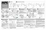
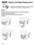
Back-UPS RS
APC BACK-UPS RS 1500VA LCD 120V
APC Back-UPS RS, 865 Watts / 1500
VA,Input 120V / Output 120V
Includes: CD with software, USB cable, User
Manual
Standard Lead Time: Usually in Stock
BR1500LCD Features
Battery failure
notification
Battery-protected and
surge-only outlets
Provides early-warning fault analysis on batteries enabling timely preventive
maintenance
Reserves power capacity and run time for connected equipment that require
battery back-up while providing surge only protection for less critical
equipment
Cold-start capable
Provides temporary battery power when the utility power is out.
Hot-swappable
Ensures clean, uninterrupted power to protected equipment while batteries
batteries
are being replaced
Disconnected battery Warns when a battery is not available to provide backup power.
notification
Dataline Surge
Provides protection of connected equipment from power surges on the data
Protection
lines.
Boost Automatic
Preserves battery life and maximizes runtime by correcting low voltages
Voltage Regulation
without discharging the battery.
(AVR)
Automatic self-test
Periodic battery self-test ensures early detection of a battery that needs to be
replaced.
Adjustable voltageMaximizes useful battery life by widening the input voltage window or
transfer points
tightening the output voltage regulation.
Adjustable voltage
Provides the ability to adapt the UPS for optimal performance in specific
sensitivity
power environments or generator applications.
Audible Alarms
Provides notification of changing utility power and UPS conditions.
User-replaceable
Increases availability by allowing a trained user to perform upgrades and
batteries
replacements of the batteries reducing Mean Time to Repair (MTTR)
USB Connectivity
Provides management of the UPS via a USB port (not available on all
models).
Transformer-block
Protect equipment with input transformer blocks without blocking access to
spaced outlets
other receptacles.
Intelligent Battery
Maximizes battery performance, life, and reliability through intelligent,
Management
precision charging.
Safety-agency
Ensures the product has been tested and approved to work safely with the
approved
connected service provider equipment and within the specified environment.
UL, FCC, CE, C-Tick approvals.
Lifetime data recovery Provides peace of mind by providing professional data recovery services in
warranty
the event data is lost due to the failure of the unit.
Adjustable voltage
Provides the ability to adapt the Power Conditioner for optimal performance
sensitivity
in specific power environments or generator applications.
Battery replacement Allows quick, easy battery replacement.
without tools
LCD graphics display Text and mimic diagrams that display modes of operation, system parameters
and alarms.
Back-UPS RS Features & Benefits
Protection
Battery-protected and Reserves power capacity and run time for connected equipment that require
surge-only outlets
battery back-up while providing surge only protection for less critical
equipment
Boost and Trim
Gives higher application availability by correcting low and high voltage
Automatic Voltage
conditions without using the battery.
Regulation (AVR)
Data line surge
Provides protection of connected equipment from power surges on the data
protection
lines.
Safety-agency
Ensures the product has been tested and approved to work safely with the
approved
connected service provider equipment and within the specified environment.
UL, FCC, CE, C-Tick approvals.
Power conditioning
Protects connected loads from surges, spikes, lightning, and other power
disturbances.
Convenience
Audible Alarms
Automatic restart of
loads after UPS
shutdown
Automatic self-test
Battery replacement
without tools
LED status indicators
Cold-start capable
Hot-swappable
batteries
Resettable circuit
breakers
Transformer-block
spaced outlets
User-replaceable
batteries
Provides notification of changing utility power and UPS conditions.
Automatically starts up the connected equipment upon the return of utility
power.
Periodic battery self-test ensures early detection of a battery that needs to be
replaced.
Allows quick, easy battery replacement.
Quickly understand unit and power status with visual indicators.
Provides temporary battery power when the utility power is out.
Ensures clean, uninterrupted power to protected equipment while batteries
are being replaced
Enables a quick recovery from overload events.
Protect equipment with input transformer blocks without blocking access to
other receptacles.
Increases availability by allowing a trained user to perform upgrades and
replacements of the batteries reducing Mean Time to Repair (MTTR)
Manageability
Adjustable voltage
sensitivity
Adjustable voltagetransfer points
Serial Connectivity
USB Connectivity
Multiple mounting
methods
Intelligent Battery
Management
Provides the ability to adapt the UPS for optimal performance in specific
power environments or generator applications.
Maximizes useful battery life by widening the input voltage window or
tightening the output voltage regulation.
Provides management of the UPS via a serial port.
Provides management of the UPS via a USB port (not available on all
models).
Allows for standardization on one product for use in different environments.
Micro-processor controlled battery charging and diagnostic testing ensures
maximum battery life.
Output
Output Power Capacity
865 Watts / 1500 VA
Max Configurable Power
865 Watts / 1500 VA
Nominal Output Voltage
120V
Output Frequency (sync to mains) 60 Hz
Crest Factor
3:1
Waveform Type
Stepped approximation to a sinewave
Output Connections
(2) NEMA 5-15R (Surge Protection)
(6) NEMA 5-15R (Battery Backup)
Input
Nominal Input Voltage
120V
Input Frequency
60 Hz +/- 3 Hz
Input Connections
NEMA 5-15P
Cord Length
1.83 meters
Input voltage range for main
operations
88 - 139V
Maximum Input Current
12A
Input Breaker Capacity
15A
Batteries & Runtime
Battery Type
Maintenance-free sealed Lead-Acid battery with suspended electrolyte : leakproof
Typical recharge time
16 hour(s)
Replacement Battery
APCRBC109
RBC™ Quantity
1
Typical Backup Time
at Half Load
11.7 minutes (432.5 Watts)
Typical Backup Time
at Full Load
3.1 minutes (865 Watts)
Runtime Chart
Back-UPS RS
Communications & Management
Control panel
Multi-function LCD status and control console
Audible Alarm
Alarm when on battery : distinctive low battery alarm : overload continuous tone
alarm
Surge Protection and Filtering
Surge energy rating
340 Joules
Filtering
Full time multi-pole noise filtering : 5% IEEE surge let-through : zero clamping
response time : meets UL 1449
Data Line Protection
RJ-45 Modem/Fax/DSL/10-100 Base-T protection,Co-axial Video / Cable protection
Physical
Maximum Height
222.00 mm
Maximum Width
133.00 mm
Maximum Depth
356.00 mm
Net Weight
13.95 KG
Shipping Weight
15.55 KG
Shipping Height
305.00 mm
Shipping Width
248.00 mm
Shipping Depth
457.00 mm
Master Carton Units
1.00
Master Carton Weight
15.55 KG
Color
Charcoal
SCC Codes
0073130424791 3
Environmental
Operating Environment
0 - 40 °C
Operating Relative Humidity
0%
Operating Elevation
0-3000 meters
Storage Temperature
-5 - 45 °C
Storage Relative Humidity
0%
Storage Elevation
0-15000 meters
Audible noise at 1 meter from
surface of unit
45.00 dBA
Conformance
Regulatory Approvals
FCC Part 15 Class B,FCC Part 68,NOM,TUV
Standard Warranty
3 years repair or replace
ROHS/WEEE Compliance
RoHS
**The time to recharge to 90% of full battery capacity following a discharge to shutdown using a load rated for 1/2 the full
load rating of the UPS.
SPECIFICATIONS
TROUBLESHOOTING
Problem
Possible Cause
Back-UPS will not switch on.
Corrective Action
Back-UPS is not connected to the AC power source.
Ensure the Back-UPS is securely connected to an AC outlet.
Back-UPS circuit breaker “tripped”.
Disconnect non-essential equipment from the Back-UPS. Reset the
circuit breaker. Switch on the Back-UPS, and plug in devices one at a
time. If the circuit breaker trips again, disconnect the device that
caused the breaker to trip.
Internal battery is not connected.
Connect the battery cartridge (see Connect Battery Cartridge).
Utility input voltage quality is out of range.
Consider adjusting the transfer voltage and sensitivity. See Transfer
Voltage and Sensitivity Adjustment.
Back-UPS does not power essential
equipment during an outage.
Equipment is plugged into a Surge Only outlet.
Unplug the device from the 'Surge Only' outlet, and move to a 'Battery
Backup' outlet.
Back-UPS operates on battery although
utility power is provided.
The UPS's plug has partially pulled out of the wall outlet, the wall outlet was turned off, or its circuit breaker
tripped.
Verify the Back-UPS's plug is fully inserted into the wall, and power is
present at the wall outlet by plugging in a known good device.
Unit is performing an automatic self test.
No action is neccessary.
Utility input voltage is out of range, frequency is out of
range, or the waveform is distorted.
Consider adjusting the transfer voltage and sensitivity. Reference
Transfer Voltage and Sensitivity Adjustment.
Back-UPS is overloaded.
Unplug non-essential equipment (printers, scanners, etc) from the Battery Backup outlets, and plug them into 'Surge Only' outlets.
Back-UPS battery cartridge discharged due to a recent
power outage, and has not had time to recharge.
Charge the battery cartridge for 16 hours. Back-UPS runtime is
reduced until the battery cartridge is fully charged.
Back-UPS does not provide expected
amount of backup time.
Battery has reached end of life.
Refer to Replace Battery Cartridge, and replace the battery cartridge.
Replace Battery indicator is on.
Battery has reached end of life.
Refer to Replace Battery Cartridge, and replace the battery cartridge.
Overload indicator is on, or flashing.
Connected equipment is drawing more power than the
Back-UPS can provide.
Move one or more equipment power plugs from Battery Backup outlets to Surge Only outlets.
System Fault indicator is on and all other
front panel indicators are flashing.
Internal UPS fault.
One of nine Internal UPS Fault Messages is displayed:
F01 - On-Battery Overload
F06 - Relay Welding
F02 - On-Battery Output Short F07 - Temperature
F03 - On-Battery XCap Overload F08 - Fan Fault
F04 - Clamp Short
F09 - Internal Fault
F05 - Charger Fault
Contact APC Technical Support (see Contact Information).
LIMITED WARRANTY
TRANSFER VOLTAGE and SENSITIVITY ADJUSTMENT
In situations where the Back-UPS or connected equipment appears too sensitive to the
input voltage, it may be necessary to adjust the transfer voltage. This is a simple task
using the front panel power on/off pushbutton. To adjust the transfer voltage, proceed
as follows:
1. Plug the Back-UPS into the utility power source, but do not turn the unit on.The
Back-UPS will be in standby mode (there are no indicators lit).
2. Press and hold the front panel on/off switch in for 10 seconds, until all the
indicators on the Back-UPS flash to acknowledge it has entered sensitivity
programming mode. Release the on/off button, the blocks in the Back-UPS's
LOAD bar shown on the LCD indicate it's current sensitivity setting, as described
in the table below.
Note: The Back-UPS automatically exits programming mode in five seconds if no
buttons are pressed, and no operations are run.
Reference the table below to determine which sensitivity setting to select.
Input Voltage
Range
(utility
operation)
Indicators
Flashing
Sensitivity
Setting
1
(one block of
the Load Bar)
Low
78 to 142 Vac Input voltage is extremely low or
extremely high. Not recommended
for computer loads.
2
(three blocks of
the Load Bar)
Medium
(factory
default)
88 to 139 Vac The Back-UPS frequently goes on
battery (ON BATT).
3
(five blocks of
the Load Bar)
High
Use When
88 to 136 Vac The connected equipment is
sensitive to voltage fluctuations.
4. To select the Low Sensitivity setting, press and release the ON/OFF
switch several times until only the first block in the Load Bar is lit and
flashing, then release the switch.
5. To select the Medium Sensitivity setting (the unit's default), press and
release the ON/OFF switch until the first three blocks in the Load Bar
are lit and flashing, then release the switch.
6. To select the High Sensitivity setting, press and release the ON/OFF
switch until all five blocks of the Load Bar are lit and flashing, and then
release the switch.
7. If there are no operations for five seconds, the Back-UPS will
automatically exit sensitivity programming mode, and the Back-UPS is
ready for normal operation.
Item
ORDER REPLACEMENT
REPLACEMENT BATTERY
BATTERY
ORDER
1300 VA
/
1500 VA
On-line Input Voltage Range
(default settings)
88 to 139 VAC
Automatic Voltage Regulation (AVR)
On-line Frequency Range
On-battery Waveshape
Maximum Load
Typical Recharge Time
Operating Temperature
+12% (Boost mode only)
57 to 63 Hz (Autosensing)
Stepped Sine Wave
1300 VA: 780 W
1500 VA: 865 W
1300 VA: 16 Hours and 1500 VA: 16 Hours
Storage Temperature
32o to 104oF
0o to 40oC
23o to 113oF
-5o to 45oC
Operating / Storage Relative Humidity 0 to 95% non-condensing
Size (H x W x D)
8.7 inch x 5.1 inch x 13.8 inch
220 mm x 130 mm x 350 mm
Weight
1300 VA: 29.7 lbs (13.5 kg)
1500 VA: 30.7 lbs (14.0 kg)
Shipping Weight
1300 VA: 33.2 lbs (15.1 kg)
1500 VA: 34.2 lbs (15.6 kg)
EMI Classification
FCC / DOC Class B Certified
On Battery Run-Time
Go to: http://www.apc.com/product
Approvals
TUV C-US, NOM
Notice: This device complies with Parts 68 and 15 of the FCC rules.Operation is
subject to the following two conditions: (1) This device may not cause harmful
interference. (2) This device must accept any interference received, including
interference that may cause undesired operation.
There is a label on the bottom of this equipment that contains, among other
information, the FCC registration number and ringer equivalence number (REN) for
this equipment. If requested, this information must be provided to the telephone
company.
The battery cartridge typically lasts 3 to 6 years, a shorter period if subjected to
frequent outages or elevated temperatures. For the BR1300LCD, BR1500LCD,
BX1300LCD and BX1500LCD order part APCRBC109. Please recycle spent
battery cartridges.
WARRANTY
The standard warranty is three (3) years from the date of purchase. APC’s
standard procedure is to replace the original unit with a factory reconditioned unit.
Customers who must have the original unit back due to the assignment of asset
tags and set depreciation schedules must declare such a need at first contact with
an APC Technical Support representative. APC will ship the replacement unit
once the defective unit has been received by the repair department, or cross-ship
upon the receipt of a valid credit card number. The customer pays for shipping the
unit to APC. APC pays ground freight transportation costs to ship the replacement
unit to the customer.
SERVICE
If the Back-UPS arrived damaged, notify the carrier.
If the Back-UPS requires service, do not return it to the dealer. The following
steps should be taken:
1.
2.
3.
Consult the Troubleshooting section to eliminate common problems.
If the problem persists, go to http://www.apc.com/support/.
If the problem still persists, contact APC Technical Support.
• Have the Back-UPS model number, serial number and date of purchase
available. Be prepared to troubleshoot the problem with an APC Technical
Support representative. If this is not successful, APC will issue a Return
Merchandise Authorization (RMA) number and a shipping address.