1
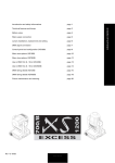
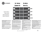
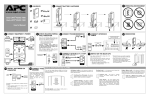
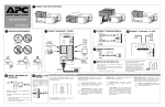
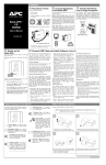
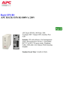
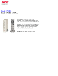
®
2 CONNECT BATTERY CARTRIDGE
1 CONTENTS
RJ-45
RJ-45
USB
RJ-45
Coax
Coax
w w w.apc.com
1
Back-UPS® XS 900
Back-UPS® XS 1200
2
Æ
User’s Manual
3 OPERATING ENVIRONMENT
53 CHECK BUILDING WIRING
4 CONNECT EQUIPMENT / POWER
FAULT INDICATOR
FAX
Printer or Scanner
32 - 104o F (0 - 40o C)
Computer
6 CONNECT MODEM/PHONE/FAX and
TVSS Ground
If the rear panel Building Wiring Fault (red) indicator is lit,
a potential shock hazard exists due to one of the following
conditions:
• Open or high resistance ground
• Hot and Neutral polarities are reversed
• Overloaded neutral circuit
Improper building wiring should be corrected by a
qualified electrician. Do not use the Back-UPS until the
condition that caused the fault is corrected.
Note: Improper building wiring will not prevent the BackUPS from operating, but it will limit its protection
capability.
RJ-45/
RJ-11
RJ-45/
RJ-11
Phone
Jack
External Disk or
CD / DVD Drive
Monitor
RJ-45/
RJ-11
From stand alone
data line surge
suppressor or
electronic device
If needed, the Back-UPS
features a TVSS ground screw
for connecting the ground lead
of any additional stand alone
surge suppression devices,
such as an APC ProtectNet
product; or any electronic
device with an external ground
connection.
RJ-45/
RJ-11
Computer
Modem Port
OR
Phone or Fax
7 CONNECT COAXIAL CABLES
CABLE IN
Coaxial Cable
CABLE IN
CABLE OUT
Building
Wiring
Fault
To 120 VAC Wall Outlet
9 CONNECT DATA LINE AND
INSTALL SOFTWARE ON
COMPUTER (Optional)
CABLE IN
USB
There are four status indicators (lights) on the front
panel of the Back-UPS (On Line, On Battery, Overload,
and Replace Battery).
On Line
Overload (red) - is lit whenever power demand has
exceeded the capacity of the Back-UPS.
Continuous Tone - this alarm is sounded
whenever the Battery Backup outlets are
overloaded.
On Battery
RJ-45
CABLE OUT
To USB
Port
STATUS INDICATORS, ALARMS and CIRCUIT BREAKER
Building
Wiring
Fault
1. Insert CD into computer, and on-screen instructions
should appear automatically. Follow instructions to
complete installation. Note: if the on-screen
instructions do not appear automatically (Autoplay is
disabled), then perform steps 2 and 3 below.
2. On the computer desktop of the display, double-click
on My Computer.
3. Double-click on the CD-ROM drive icon and follow
the on-screen instructions.
Installation of the included software is the only way to
take advantage of the auto shutdown capabilities that
Back-UPS offers.
Follow the
on-screen
instructions.
Overload
Replace Battery
On Line (green) - is lit whenever utility power is
powering the Battery Backup outlets.
On Battery (yellow) - is lit whenever the battery of
the Back-UPS is powering equipment connected to the
Battery Backup Outlets.
Four Beeps Every 30 Seconds - this alarm is
sounded whenever the Back-UPS is running On
Battery. Consider saving work in progress.
Continuous Beeping - this alarm is sounded
whenever a low battery condition is reached.
Battery run-time is very low. Promptly save any
work in progress and exit all open applications.
Shut down the operating system, computer and
the Back-UPS.
Replace Battery (red) - is lit whenever the battery is
near the end of its useful life, or if the battery is not
connected (see above). A battery that is near the end of
its useful life has insufficient run-time and should be
replaced.
Chirps for 1 Minute Every 5 Hours - this alarm
is sounded whenever the battery has failed the
automatic diagnostic test.
Circuit Breaker - the circuit breaker button located on
the rear panel of the Back-UPS will stick out if an
overload condition forces the Back-UPS to disconnect
itself from utility power. If the button sticks out,
disconnect non-essential equipment. Reset the circuit
breaker by pushing the button inward.
CABLE OUT
Note: Allow the Back-UPS to charge for a full 18 hours
(XS 900) or 24 hours (XS 1200) prior to use.
Press the front panel Power ON/OFF switch and observe
that the following events occur after pressing and
releasing the switch:
• The green On Line indicator flashes.
• The yellow On Battery indicator lights while a SelfTest is being performed.
• When Self-Test has successfully completed, only the
green On Line indicator will be lit.
• If the internal battery cartridge is not connected (see
Step 2 above), the green On Line indicator and red
Replace Battery indicators will light. The Back-UPS
will also emit a chirping sound.
ON LINE
ON BATTERY
From Cable
Provider
To Cable
Modem
Building Wiring Fault
Indicator
8 SWITCH ON THE BACK-UPS
OVERLOAD
REPLACE BATTERY
Coaxial Cable
Building
Wiring
Fault
TRANSFER VOLTAGE and SENSITIVITY ADJUSTMENT
In situations where the Back-UPS or connected equipment appears too sensitive to input
voltage, it may be necessary to adjust the transfer voltage. This is a simple task requiring use
of the front panel pushbutton. To adjust the transfer voltage, proceed as follows:
1. Plug the Back-UPS into the utility power source but do not turn the unit on. The BackUPS will be in Standby Mode (no indicators lit).
2. Press and hold the front panel ON/OFF switch fully inward for 10 seconds, until all
LED indicators on the Back-UPS flash to acknowledge it has entered Programming
Mode. Release the ON/OFF button, and the Back-UPS's LEDs will flash per table
below, indicating it's current sensitivity setting.
Note: the Back-UPS automatically exits programming mode in 5 seconds if no buttons
are pressed.
3. Use the table below to decide which Sensitivity setting is desired.
Indicators
Flashing
Sensitivity
Setting
Input Voltage
Range
(for utility operation)
Use When
1
(yellow)
Low
78 - 142 Vac
Input voltage is extremely low or
high. Not recommended for computer
loads.
2
(yellow, and red)
Medium
(factory
default)
88 - 139 Vac
Back-UPS frequently goes On
Battery.
3
(yellow, red, and
red)
High
88 - 136 Vac
Connected equipment is sensitive to
voltage fluctuations.
4. To select the Low Sensitivity setting, press and hold the ON/OFF
switch for 1-2 seconds (until beep is heard). Upon release, the yellow
indicator will flash, indicating Low Sensitivity.
5. To select the Medium Sensitivity setting (the unit's default), press and
hold the ON/OFF switch for 1-2 seconds (until beep is heard). Upon
release, the yellow indicator will flash. Press and hold the ON/OFF
button again for 1-2 seconds (until beep is heard). Upon release, the
yellow and one red indicator will flash, indicating Medium
Sensitivity.
6. To select the High Sensitivity setting, press and hold the ON/OFF
switch for 1-2 seconds (until beep is heard). Repeat this two more
times. Upon final release, the yellow and two red indicators (bottom
three) will flash, indicating High Sensitivity.
7. The Back-UPS will automatically exit Programming Mode in five
seconds, and is ready for use.
ORDER REPLACEMENT BATTERY
The battery cartridge typically lasts 3-6 years, shorter if subjected to
frequent outages or elevated temperatures. For the XS 900, order part
number RBC5 , for the XS 1200, order APCRBC109. Please recycle
spent battery cartridges.
TROUBLESHOOTING
Problem
Back-UPS will not switch on.
SPECIFICATIONS
Possible Cause
Corrective Action
Back-UPS not connected to AC power source.
Ensure the Back-UPS is securely connected to an AC outlet.
On-line Input Voltage Range
(default settings)
Back-UPS circuit breaker “tripped”.
Disconnect non-essential equipment from the Back-UPS. Reset
(push in) the rear panel circuit breaker. Switch on the Back-UPS and
plug in devices one at a time. If the circuit breaker trips again,
disconnect the device that caused the breaker to trip.
Automatic Voltage Regulation (AVR)
On-line Frequency Range
On-battery Waveshape
Maximum Load
Typical Recharge Time
Operating Temperature
Internal battery is not connected.
Connect battery cartridge (see Connect Battery Cartridge).
Utility input voltage quality is out of range.
Consider adjusting the transfer voltage and sensitivity. See Transfer
Voltage and Sensitivity Adjustment.
Back-UPS does not power essential
equipment during an outage.
Equipment was plugged into a Surge Only outlet.
Unplug device from 'Surge Only' outlet and move to a 'Battery
Backup' outlet.
Back-UPS operates on battery
although utility power exists.
The UPS's plug has partially pulled out of the wall
outlet, wall outlet has been turned off, or its circuit
breaker has tripped.
Verify the UPS's plug is fully inserted into the wall, and that power
is present at the wall outlet.
Unit is in the midst of performing an automatic self
test.
No action is neccessary.
Utility input voltage is out of range, frequency is out
of range or the wave form is distorted.
Consider adjusting the transfer voltage and sensitivity. See Transfer
Voltage and Sensitivity Adjustment.
Back-UPS is heavily loaded.
Unplug non-essential equipment (printers, scanners, etc) from the
Battery Backup outlets and plug into 'Surge Only' outlets.
Back-UPS battery cartridge is discharged due to
recent power outage and has not had time to recharge.
Charge the battery cartridge for 18 hours (XS 900) or 24 hours (XS1200). Back-UPS runtime is reduced until the battery cartridge is
fully charged.
Battery has reached the end of its life.
Replace battery cartridge (see Order Replacement Battery
Cartridge).
Red Replace Battery indicator is on.
Battery has reached the end of its life.
Refer to Replace Battery Cartridge, and replace the battery cartridge.
Red Overload indicator is on or
flashing.
Connected equipment is drawing more power than
the Back-UPS can provide.
Move one or more equipment power plugs from Battery Backup
outlets to Surge Only outlets.
Green On Line indicator is on and all
other front panel indicators are
flashing.
Internal UPS fault.
Contact APC Technical Support (see Contact Information).
Back-UPS does not provide expected
backup time.
Item
Storage Temperature
Operating / Storage Relative Humidity
Size (H x W x D)
LIMITED WARRANTY
900 VA
1200 VA
88 - 139 VAC
+12% (Boost Only)
57 - 63 Hz (Autosensing)
Stepped Sine Wave
900 VA: 540 W
1200 VA: 720 W
900 VA: 18 Hours
1200 VA: 24 Hours
32o to 104oF
0o to 40oC
23o to 113oF
-5o to 45oC
0 to 95% non-condensing
8.7 inch X 5.1 inch X 13.8 inch
220 mm X 130 mm X 350 mm
Weight
900 VA: 27.5 lbs (12.5 kg)
1200 VA: 29.7 lbs (13.5 kg)
Shipping Weight
900 VA: 31.0 lbs (14.1 kg)
1200 VA: 33.2 lbs (15.1 kg)
EMI Classification
FCC / DOC Class B Certified
On Battery Run-Time
See http://www.apc.com/product
Approvals
CSA NRTL/C, NOM
Notice: This device complies with part 68 and 15 of the FCC rules.Operation is subject to
the following two conditions: (1) This device may not cause harmful interference. (2) This
device must accept any interference received, including interference that may cause
undesired operation.
On the bottom of this equipment is a label that contains, among other information, the
FCC registration number and ringer equivalence number (REN) for this equipment. If
requested, this information must be provided to the telephone company.
The standard warranty is three (3) years from the date of purchase. APC’s standard
procedure is to replace the original unit with a factory reconditioned unit. Customers
who must have the original unit back due to the assignment of asset tags and set
depreciation schedules must declare such a need at first contact with an APC Technical
Support representative. APC will ship the replacement unit once the defective unit has
been received by the repair department, or cross-ship upon the receipt of a valid credit
card number. The customer pays for shipping the unit to APC. APC pays ground freight
transportation costs to ship the replacement unit to the customer.
SERVICE
If the Back-UPS arrived damaged, notify the carrier.
If the Back-UPS requires service, do not return it to the dealer. The following steps
should be taken:
1.
2.
3.
Consult the Troubleshooting section to eliminate common problems.
If the problem persists, go to http://www.apc.com/support/.
If the problem still persists, contact APC Technical Support.
• Have the Back-UPS model number, serial number and date of purchase
available. Be prepared to troubleshoot the problem with an APC Technical
Support representative. If this is not successful, APC will issue a Return
Merchandise Authorization (RMA) number and a shipping address.
CONTACT INFORMATION
Technical Support
Internet
USA / Canada
Mexico
Worldwide
http://www.apc.com/support
http://www.apc.com
1.800.800.4272
292.0253 / 292.0255
+1.401.789.5735
REPLACE BATTERY CARTRIDGE
1
2
990-2462 Copyright © 2006 American Power Conversion All rights reserved.
APC and Back-UPS are registered trademarks of American Power Conversion.
All other trademarks are the property of their respective owners.