1
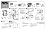
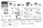
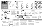
Back-UPS RS
APC BACK-UPS RS 800VA 230V
APC Back-UPS RS, 540 Watts / 800
VA,Input 230V / Output 230V, Interface Port
USB
Includes: CD with software, Cord management
straps, Documentation CD, Qty 2 - Detachable
IEC C13 to IEC C14 power cords, Telephone
Cable, USB cable, User Manual, Wall-mounting
template
Standard Lead Time: Usually in Stock
BR800I Features
Serial Connectivity
USB Connectivity
Serial Connectivity
Use any Home Automation network to monitor and control the S20 through
its RS-232 serial port. For information on how to communicate with the S20,
see APC's Application Note #102. Crestron and AMX installers should visit
their respective websites for information on how to integrate the S20 into
those networks.
Provides management of the UPS via a USB port (not available on all
models).
Provides management of the UPS via a serial port.
Back-UPS RS Features & Benefits
Protection
Battery-protected and Reserves power capacity and run time for connected equipment that require
surge-only outlets
battery back-up while providing surge only protection for less critical
equipment
Boost and Trim
Gives higher application availability by correcting low and high voltage
Automatic Voltage
conditions without using the battery.
Regulation (AVR)
Provides protection of connected equipment from power surges on the data
Data line surge
protection
lines.
Safety-agency
Ensures the product has been tested and approved to work safely with the
approved
connected service provider equipment and within the specified environment.
UL, FCC, CE, C-Tick approvals.
Power conditioning
Protects connected loads from surges, spikes, lightning, and other power
disturbances.
Convenience
Audible Alarms
Automatic restart of
loads after UPS
shutdown
Automatic self-test
Battery replacement
without tools
LED status indicators
Cold-start capable
Hot-swappable
batteries
Resettable circuit
breakers
Transformer-block
spaced outlets
Provides notification of changing utility power and UPS conditions.
Automatically starts up the connected equipment upon the return of utility
power.
Periodic battery self-test ensures early detection of a battery that needs to be
replaced.
Allows quick, easy battery replacement.
Quickly understand unit and power status with visual indicators.
Provides temporary battery power when the utility power is out.
Ensures clean, uninterrupted power to protected equipment while batteries
are being replaced
Enables a quick recovery from overload events.
Protect equipment with input transformer blocks without blocking access to
other receptacles.
User-replaceable
batteries
Increases availability by allowing a trained user to perform upgrades and
replacements of the batteries reducing Mean Time to Repair (MTTR)
Manageability
Adjustable voltage
sensitivity
Adjustable voltagetransfer points
Serial Connectivity
USB Connectivity
Multiple mounting
methods
Intelligent Battery
Management
Provides the ability to adapt the UPS for optimal performance in specific
power environments or generator applications.
Maximizes useful battery life by widening the input voltage window or
tightening the output voltage regulation.
Provides management of the UPS via a serial port.
Provides management of the UPS via a USB port (not available on all
models).
Allows for standardization on one product for use in different environments.
Micro-processor controlled battery charging and diagnostic testing ensures
maximum battery life.
Output
Output Power Capacity
540 Watts / 800 VA
Max Configurable Power
540 Watts / 800 VA
Nominal Output Voltage
230V
Output Connections
(2) IEC 320 C13 (Surge Protection)
(4) IEC 320 C13 (Battery Backup)
Input
Nominal Input Voltage
230V
Input Frequency
47 - 63 Hz
Input Connections
IEC-320 C14
Cord Length
1.83 meters
Input voltage range for main
operations
175 - 295V
Input voltage adjustable range for 160 - 300V
mains operation
Batteries & Runtime
Battery Type
Maintenance-free sealed Lead-Acid battery with suspended electrolyte : leakproof
Included Battery Modules
1
Typical recharge time
8 hour(s)
Replacement Battery
RBC32
RBC™ Quantity
1
Typical Backup Time
at Half Load
17.8 minutes (270 Watts)
Typical Backup Time
at Full Load
5.3 minutes (540 Watts)
Runtime Chart
Back-UPS RS
Energy Use/Efficiency
Curve fit to measured efficiency data. All measurements taken in
normal operating mode, at typical environmental conditions, with
nominal electrical input and resistive load output.
View Enlarged Chart
Communications & Management
Interface Port(s)
USB
Control panel
LED status display with On Line : On Battery : Replace Battery and Overload
indicators
Audible Alarm
Alarm when on battery : distinctive low battery alarm : configurable delays
Surge Protection and Filtering
Surge energy rating
320 Joules
Filtering
Full time multi-pole noise filtering : 5% IEEE surge let-through : zero clamping
response time : meets UL 1449
Data Line Protection
RJ-11 Modem/Fax/DSL protection (two wire single line),RJ45 10/100 Base-T
Ethernet protection
Physical
Maximum Height
229.00 mm
Maximum Width
102.00 mm
Maximum Depth
324.00 mm
Net Weight
9.32 KG
Shipping Weight
10.23 KG
Shipping Height
305.00 mm
Shipping Width
229.00 mm
Shipping Depth
432.00 mm
Master Carton Units
2.00
Master Carton Weight
48.00 lbs.
Color
Beige
SCC Codes
0073130419246 6
Units per Pallet
40.00
Environmental
Operating Environment
0 - 40 °C
Operating Relative Humidity
0%
Operating Elevation
0-3000 meters
Storage Temperature
-5 - 45 °C
Storage Relative Humidity
0%
Storage Elevation
0-15000 meters
Audible noise at 1 meter from
surface of unit
45.00 dBA
Online Thermal Dissipation
170.00 BTU/hr
Conformance
Regulatory Approvals
A-tick,C-tick,CE,GOST,GS Mark,VDE
Standard Warranty
2 years repair or replace
ROHS/WEEE Compliance
RoHS
**The time to recharge to 90% of full battery capacity following a discharge to shutdown using a load rated for 1/2 the full
load rating of the UPS.
SPECIFICATIONS
TROUBLESHOOTING
SERVICE
If the Back-UPS arrived damaged, notify the carrier.
Problem
Back-UPS will not switch on.
Possible Cause
Item
Corrective Action
Back-UPS not connected to AC power source.
Ensure the Back-UPS is securely connected to an AC outlet.
Back-UPS circuit breaker “tripped”.
Disconnect non-essential equipment from the Back-UPS. Reset
(push in) the rear panel circuit breaker. Switch on the Back-UPS
and plug in devices one at a time. If the circuit breaker trips
again, disconnect the device that caused the breaker to trip.
Utility input voltage quality is out of range.
Consider adjusting the transfer voltage and sensitivity. See
Transfer Voltage and Sensitivity Adjustment.
Specification
On-line Input Voltage Range
(default settings)
176 - 294 Vac
Automatic Voltage Regulation (AVR)
+12%
On-line Frequency Range
47 - 63 Hz (autosensing)
On-battery Waveshape
Stepped Sine Wave
Maximum Load
800 VA - 540 W
Internal battery cartridge is not connected.
Connect battery cartridge (see Connect Battery Cartridge).
Typical Recharge Time
8 Hours
Back-UPS does not power
essential equipment during an
outage.
Equipment plugged into a Surge Only outlet.
Unplug device from 'Surge Only' outlet and move to a 'Battery
Backup' outlet.
Operating Temperature
o
Back-UPS operates on battery
although utility power exists.
Back-UPS circuit breaker “tripped”.
Disconnect non-essential equipment from the Back-UPS. Reset
(push in) the rear panel circuit breaker. Switch the Back-UPS on
and plug equipment in one-at-a-time. If the circuit breaker trips
again, disconnect the device that caused the breaker to trip.
Storage Temperature
0 to 40oC
(32o to 104oF)
-5o to 45oC
(23o to 113oF)
Operating / Storage Relative Humidity
0 to 95% non-condensing
Utility input voltage quality is out of range.
Consider adjusting the transfer voltage and sensitivity. See
Transfer Voltage and Sensitivity Adjustment.
Size (H x W x D)
Back-UPS is heavily loaded.
Unplug non-essential equipment (printers, scanners, etc) from
the Battery Backup outlets and plug into 'Surge Only' outlets.
Weight
9.3 kg (20.5 lbs)
Back-UPS battery cartridge is discharged due to
recent power outage and has not had time to
recharge.
Charge the battery cartridge for 8 hours. Back-UPS runtime is
reduced until the battery cartridge is fully charged.
Shipping Weight
9.9 kg (22 lbs)
EMI Classification
Battery has reached the end of its life.
Replace battery cartridge (see Order Replacement Battery
Cartridge).
Red Replace Battery indicator is
flashing. Green On Line indicator
is on.
Internal battery cartridge is not connected.
Connect battery cartridge (see Connect Battery Cartridge).
Red Replace Battery indicator is
on.
Battery has reached the end of its life.
Replace the battery cartridge (see Order Replacement Battery
Cartridge).
Red Overload indicator is on or
flashing.
Connected equipment is drawing more power than
the Back-UPS can provide.
Move one or more equipment power plugs from Battery Backup
outlets to Surge Only outlets.
Green On Line indicator is on and
all other front panel indicators are
flashing.
Internal UPS fault.
Contact APC Technical Support (see Contact Information).
Back-UPS does not provide
expected backup time.
ORDER REPLACEMENT BATTERY CARTRIDGE
The battery cartridge typically lasts 3-6 years, shorter if subjected to frequent outages or elevated temperatures. Order part number RBC32.
Please recycle spent battery cartridges.
REPLACE BATTERY CARTRIDGE
1
2
23 x 10 x 32 cm
(9 x 4 x 12.75 inch)
EN 50091-1, EN 60950, EN 50091-2, EN
61000-3-2, EN 6100-3-3,
EN 55022 Class B
On Battery Run-Time
TRANSFER VOLTAGE AND SENSITIVITY
ADJUSTMENT
In situations where the Back-UPS or connected equipment appears too sensitive
to input voltage, it may be necessary to adjust the transfer voltage. This is a
simple task requiring use of the front panel pushbutton. To adjust the transfer
voltage, proceed as follows:
1. Plug the Back-UPS into the utility power source. The Back-UPS will be in a
Standby Mode (no indicators lit).
2. Press the front panel pushbutton fully inward for 10 seconds. All indicators
on the Back-UPS will flash to acknowledge going into Programming Mode.
3. The Back-UPS will then indicate its current Sensitivity Setting, as shown in
the following table.
Indicators
Flashing
Sensitivity
Setting
1
(yellow)
Low
Input Voltage
Range
(for utility
operation)
156 - 300 Vac Input voltage is extremely low or
high. Not recommended for
computer loads.
2
Medium
176 - 294 Vac
(yellow, (factory default)
and red)
3
4
3
(yellow,
red, and
red)
High
Use When
Back-UPS frequently goes On
Battery.
176 - 288 Vac Connected equipment is sensitive
to voltage fluctuations
(recommended).
4. To select the Low Sensitivity setting, press the pushbutton until the yellow
indicator is flashing.
5. To select the Medium Sensitivity setting, press the pushbutton until the
yellow and red indicators (second and third from the top) are flashing.
6. To select the High Sensitivity setting, press the pushbutton until yellow and
both red indicators (bottom three) are flashing.
7. To exit without changing the Sensitivity Setting, press the pushbutton until
the green indicator is flashing.
8. Once in Programming Mode, if the pushbutton is not pressed within 5
seconds, the Back-UPS will exit Programming Mode; all indicators will
extinguish.
If the Back-UPS requires service, do not return it to the dealer. The following
steps should be taken:
1.
2.
3.
4.
Consult the Troubleshooting section to eliminate common problems.
If the problem persists, go to http://www.apc.com/support/.
If the problem still persists, contact APC Technical Support.
Have the Back-UPS model number, serial number and date of purchase
available. Be prepared to troubleshoot the problem with an APC Technical
Support representative. If this is not successful, APC will issue a Return
Merchandise Authorization (RMA) number and a shipping address.
LIMITED WARRANTY
The standard warranty is two (2) years from the date of purchase. APC’s standard
procedure is to replace the original unit with a factory reconditioned unit.
Customers who must have the original unit back due to the assignment of asset
tags and set depreciation schedules must declare such a need at first contact with
an APC Technical Support representative. APC will ship the replacement unit
once the defective unit has been received by the repair department, or cross-ship
upon the receipt of a valid credit card number. The customer pays for shipping the
unit to APC. APC pays ground freight transportation costs to ship the replacement
unit to the customer.