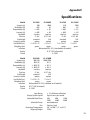
1
Table of Contents
Introduction ...................................................................................................................... 2
Section One ....................................................................................................................... 3
Installing Your Balance ............................................................................................. 3
SETUP ..........................................................................................................................3
Section Two ....................................................................................................................... 4
Understanding Your Balance ................................................................................. 4
KEYBOARD FUNCTIONS ........................................................................................ 4
LED INDICATORS ..................................................................................................... 4
DISPLAY MESSAGES ............................................................................................... 4
Section Three .................................................................................................................... 5
Using Your Balance .................................................................................................... 5
BASIC WEIGHING ..................................................................................................... 5
WEIGHING WITH A CONTAINER ........................................................................ 5
DUAL RANGE FEATURE (EL 410D & EL 4100D) ............................................ 5
INTERFACING WITH A COMPUTER ................................................................... 6
PRINTING OUT INFORMATION ........................................................................... 6
Appendix I .......................................................................................................................... 7
User Setups .................................................................................................................... 7
CALIBRATION ............................................................................................................ 8
SETTING FUNCTION OF MODE KEY TO PRINT OR HOLD .......................... 9
SETTING THE BAUD RATE ................................................................................. 11
FIRMWARE VERSION ........................................................................................... 12
RESTORING THE FACTORY DEFAULT SETUPS ........................................... 13
ENVIRONMENTAL CUSTOMIZATION ............................................................ 14
TEMPERATURE COMPENSATION CALIBRATION ....................................... 16
Appendix II ...................................................................................................................... 19
RS-232 Serial Data Communications ................................................................ 19
Receiving Data Using the Immediate Print Symbol ............................... 19
The RS-232 Interface Hardware ...................................................................... 20
Appendix III ..................................................................................................................... 21
Accessories and Options ....................................................................................... 21
Appendix IV .................................................................................................................... 22
In Case of Difficulty .................................................................................................. 22
Appendix V ..................................................................................................................... 23
Specifications ............................................................................................................ 23
Appendix VI .................................................................................................................... 24
Limited 3 Year Warranty ........................................................................................ 24
Introduction
Thank you for purchasing a Setra precision balance. The fine workmanship
and durable construction should provide years of reliable service. While
your balance is easy to operate, it is advisable to read this guide carefully
before use. It is designed to help you perform weighing and related operations quickly and accurately.
This manual is divided into four major sections. Section One, “Installing Your
Balance,” explains where to put your balance, how to level it and install the
pan, and how to get started. Section Two, “Understanding Your Balance,”
explains the various keys, displays, and messages you will encounter while
using your balance. Section Three, “Using Your Balance,” provides the detailed instructions necessary to perform various operations. Following Section Three are appendices which include initial balance setups, RS-232 information, accessory information, troubleshooting, specifications and a warranty statement.
Typographical conventions used in this manual include the following:
2
1.
BOLD UPPER CASE CHARACTERS indicate specific keys on the balance keyboard.
2.
“Quotation marks” enclose messages seen on the balance display.
Section One
Installing Your Balance
SETUP
1. Locating your balance...
You should treat your balance as you would any piece of precision
equipment, locating it on a clean, dry surface; away from extremes of
draft and vibration.
2. Leveling your balance...
The bubble level is located underneath the loading pan. Adjust the
two front feet until the bubble is centered in the circle.
3. Installing the weighing pan...
Next, place the pan support over the shaft in the center of the unit.
Then place the pan over the pan support.
4. Connecting your balance to an AC outlet...
To power up your balance, insert the appropriate end of the AC adaptor into an electrical outlet. Now insert the connector end into the
back of the balance. The balance draws very little current from an
outlet, and should always remain plugged in. The display may be
turned off by holding down the TARE key for five seconds. This keeps
your balance always ready to use with no “warm up” time.
5. Display test...
Each time your balance is powered on, it automatically runs through a
display test lasting about thirty seconds, showing all possible segments which might be displayed, and then setting itself to zero. The
balance is then ready to be used. For best accuracy allow the balance
to warm up for 5 minutes prior to using or calibrating.
3
Section Two
Understanding Your Balance
KEYBOARD FUNCTIONS
TARE/POWER
Assigns the pan and whatever is currently being weighed a
value of zero. To turn the display off, hold this key down for
five seconds. To turn the display on press this key again.
MODE
Factory programmed to function as a print key, this key can
be changed to access different print modes or to activate
the hold feature.
LED INDICATORS
ok
g
Reading shown is stable.
Reading shown is given in grams.
DISPLAY MESSAGES
–␣ –␣ –␣ –␣ –␣ –
UnAbLE
The balance is unable to perform your requested operation.
Press the TARE key and select another operation.
HHHHHH
The weight on the pan exceeds the capacity of the balance.
LLLLLL
4
The balance is developing a stable reading.
The pan is not properly seated or has been removed.
Section Three
Using Your Balance
BASIC WEIGHING
To weigh a sample on your balance, use the following procedure:
1. Press the TARE key to zero the display.
2. Place the object(s) to be weighed on the pan.
3. Wait for the “ok” indicator, then read the weight from the display.
WEIGHING WITH A CONTAINER
To weigh objects or liquids without including the weight of the container,
use the following procedure:
1. Place the empty container on the pan. Press the TARE key, the scale will
display “–␣ –␣ –␣ –␣ –␣ –” and return to zero.
2. Wait for the “ok” indicator. Place or pour objects or liquids into the
container.
3. Wait for the “ok” indicator, the net weight will be displayed.
DUAL RANGE FEATURE (EL 410D & EL 4100D)
Each time the TARE key is pressed the display will present the higher of the
two possible weight resolutions (0.001g for the low capacity balance, and
0.01g for the high capacity balance). The dual range feature provides this
higher resolution up to 100 grams for the low capacity model, and up to
1000 grams for the high capacity model. Whenever these weights are exceeded, the balance will automatically reduce the resolution by one order
of magnitude. The higher resolution can be recovered by either removing
some weight, or by pressing the TARE key and resetting the display to zero.
Regardless of the weight on the pan the higher resolution can always be
displayed by pressing TARE. Pressing the TARE key does not increase the
capacity of the balance, thus the total weight on the pan must always be
equal to or less than the rated capacity.
5
INTERFACING WITH A COMPUTER
Your balance has a male DB9 RS-232 serial port and is designed to interface
with computer equipment. If your balance is connected to a computer,
follow the instructions in Appendix II.
PRINTING OUT INFORMATION
Your balance is designed to print out the displayed weight when connected
to an optional serial printer. To print using the CoStar SETRA 250 thermal
receipt/label printer, follow the instructions below:
1. Connect the printer’s AC adaptor to the proper electrical outlet.
2. Make sure the printer is turned on (as indicated by the printer’s green
light). If the printer is not on, press the blue power button on the front
of the printer.
3. Load the appropriate paper or label stock into the printer. (See printer
instructions for details).
4. Connect the printer to the balance’s RS-232 connector using the cable
provided.
5. Perform the necessary weighing procedures on the balance.
6. Press the MODE key on the balance.
NOTE:
6
The MODE key must be set up to perform the print function. This is the
factory default. If using label stock, the form feed command must be
programmed in User Setups (see Appendix I). When using a printer
other than the CoStar SETRA 250, set the baud rate and parity of your
balance to match the printer (see Appendix I, User Setups to select
the print mode, baud rate and parity).
Appendix I
User Setups
The outline below represents the balance's menu structure. To enter the
menu press and hold the TARE key and then press the MODE␣ key. To view the
current menu options, press the TARE key repeatedly. To select the displayed
option, press the MODE key.
Full Scale
Lower Weights
SPAN
Unspan
Stable
Select to
calibrate
MODE
Escape
FUNC
sets function
of mode key
Print
Interval
Hold
Line
Feed
Escape
Escape
300
600
1200
2400
4800
9600
Escape
BAUD
set for RS232 interface
Instant
0...
...600
Escape
0...
...18
Escape
Parity
None
Escape
Odd
Even
Escape
REF
Displays current software version
FACDEF Restores all factory defaults
TARE
Speed
POWER
CUSTOM
Environmental
Customization
CAL T
Fast
Slow
Auto
Escape
Fac TP
User TP
Escape
Hot Cal
Escape
ESCAPE Returns to weighing mode
7
CALIBRATION
To perform a span calibration, use the following procedure:
STEP 1.
0.00
MODE
TARE
POWER
0.00
Press the TARE key to zero the balance.
STEP 2.
0.00
MODE
TARE
POWER
SPAn
Hold down the TARE key then press the MODE key. Release both keys, the
display will read “SPAn” for span calibration.
STEP 3.
SPAn
MODE
TARE
POWER
2000
Press the MODE key to enter the span calibration menu. The balance’s full
capacity will be displayed. You can calibrate the balance at full capacity or at
a lower calibration point. To view the set calibration points, press the TARE
key until the desired weight is displayed.
To restore the factory calibration, press the TARE key to display “UnSPAn”
then press the MODE key. To escape, press the TARE key to display “ESCAPE”
then press the MODE key.
STEP 4.
2000
MODE
TARE
POWER
ACAL
Place on the pan calibration weight(s) equal to the displayed weight and
press the MODE key. The balance will display “ACAL” and then return to the
normal weighing mode. If the display reads “nOCAL”, check the weights and
weighing environment. This calibration procedure can only correct for ±1%
span shift.
8
SETTING FUNCTION OF MODE KEY TO PRINT OR HOLD
The MODE key may be set to either print or hold a displayed weight. The
selectable print functions are: “stable print” which will only print once a
stable reading is attained, “interval print” which may be programmed to
print at predetermined time intervals, “instant print” which will print immediately after the MODE key is pressed (note: the reading may not be stable).
The number of line feeds may also be set for label printing. The print function is set separately from the line feed setup, i.e., set the print function first
then re-enter the print menu to program the number of line feeds. The MODE
key can also be set to the hold feature in which the balance attains a stable
weight and locks it in the display until a key is pressed.
To set the function of the MODE key, use the following procedures:
STEP 1:
0.00
MODE
TARE
POWER
SPAn
Hold down the TARE key then press the MODE key. Release both keys, the
display will read “SPAn”.
STEP 2.
SPAn
MODE
TARE
POWER
FUnC
Press the TARE key again and the display will read “FUnC” for function.
NOTE: To escape anytime during this procedure, press the TARE key until
“ESCAPE” is displayed, then press the MODE key.
STEP 3.
FUnC
MODE
TARE
POWER
PrIn7
Press the MODE key to enter the function menu. The display will read “PrInT”.
Proceed to step 4a. to program the MODE key to perform a print command.
Go to step 4b. to program the MODE key to perform the hold function.
9
STEP 4:
PrIn7
MODE
TARE
POWER
S7AbLE
a. Press the MODE key to enter the print menu. The display will read "STAbLE".
For stable print
Perform step 4a. then press the MODE key to select the stable print
mode. The balance will return to the normal weighing mode.
For instant print
Perform step 4a. then press the TARE key once to display “InSTAn” for
instant and then press the MODE key. The balance will return to the
normal weighing mode.
For interval print
Perform step 4a.; press the TARE key twice to display “InTEr” for interval
print and then press the MODE key. Proceed to step 5.
For line feed
Perform step 4a. then press the TARE key three times to display “LInEFD”
and then press the MODE key. Proceed to step 6.
PrIn7
MODE
TARE
POWER
HOLd
b. To select the hold feature press the TARE key to display "HOLd" then
press the MODE key as shown in step 4a. The balance will return to the
normal weighing mode. Each time the MODE key is pressed the weight
will lock on the display until a key is pressed.
STEP 5:
In7Er
MODE
TARE
POWER
90 SEC
To view the predetermined print intervals (in seconds) press the TARE key
repeatedly. When the desired time interval is displayed, press the MODE key.
(Select zero for continuous printing.) The balance will then return to the
normal weighing mode. Pressing the MODE key will print the displayed weight
after each selected time interval (e.g., every 90 seconds). To interrupt the
interval printing press the MODE key again. To re-activate, press the MODE key.
Note:
10
Print intervals can vary up to ± .2 seconds depending on weight
variations.
STEP 6:
LInEFd
MODE
TARE
POWER
LF 4
To view the preset number of line feeds available (1-18) press the TARE key
repeatedly. To program a form feed command for the CoStar SETRA 250
printer, select “LF 0” as the number of line feeds. When the desired number
of line feeds is displayed, press the MODE key. The balance will then return to
the normal weighing mode.
SETTING THE BAUD RATE
The balance is capable of interfacing with a wide variety of computer devices. To set the baud rate (the rate at which the scale communicates with a
computer/printer) and parity, use the following procedure:
STEP 1.
0.00
MODE
TARE
POWER
SPAn
Hold down the TARE key then press the MODE key. Release both keys, to
display "SPAn".
STEP 2.
SPAn
MODE
TARE
POWER
bAUd
Press the TARE key twice, the display will read “bAUd” for baud rate.
Note:
To escape anytime during this procedure, press the TARE key until
"ESCAPE" is displayed and press the MODE key.
STEP 3.
bAUd
MODE
TARE
POWER
300
Press the MODE key to enter the baud rate menu. The display will read 300. To
view the other baud rates press the TARE key repeatedly.
11
STEP 4.
2400
MODE
TARE
POWER
PArI7Y
When the desired baud rate is displayed, press the MODE key to select it. The
display will then read "PArITY".
STEP 5.
PArI7Y
MODE
TARE
POWER
nOnE
Press the MODE key to enter the parity menu. The display will read "nOnE" for
no parity. To view the parity menu press the TARE key.
STEP 6.
nOnE
MODE
TARE
POWER
0.00
When the desired parity (none, odd, even) is displayed, press the MODE key.
The balance will then return to the normal weighing mode.
FIRMWARE VERSION
The operating software in your balance has a reference number. To display
this number, follow the procedure outlined below.
STEP 1.
0.00
MODE
TARE
POWER
SPAn
Hold down the TARE key then press the MODE key. Release both keys, the
display will read "SPAn".
STEP 2.
SPAn
MODE
TARE
POWER
Press the TARE key repeatedly to display “rEF” for reference number.
12
rEF
Note:
To escape anytime during this procedure, press the TARE key until
"ESCAPE" is displayed and press the MODE key.
STEP 3.
rEF
MODE
TARE
POWER
rEF2.00
Press the MODE key to display the software reference number.
STEP 4.
rEF2.00
MODE
TARE
POWER
0.00
Press the TARE key to return to the normal weighing mode.
RESTORING THE FACTORY DEFAULT SETUPS
The many features described in this section allow the user to customize the
balance to suit a particular application. However, in doing this it is also
possible to inadvertently set up the balance in such a way that it does not
operate as expected. To reset the factory defaults to: MODE key will print a
stable reading and then advance the printer to the next line, auto response
rate, 2400 baud, no parity, follow the steps below.
Note:
Restoring the factory defaults will return your balance to all of the
factory span and temperature calibration settings. You MUST
recalibrate (span) your balance after restoring the factory defaults. If
you are experiencing a temperature induced offset, you should also
run the temperature compensation calibration procedure.
STEP 1.
0.00
MODE
TARE
POWER
SPAn
Hold down the TARE key then press the MODE key. Release both keys, the
display will read "SPAn".
13
STEP 2.
SPAn
MODE
TARE
POWER
FACdEF
Press the TARE key repeatedly until the display reads "FACdEF" for factory
defaults.
Note:
To escape anytime during this procedure, press the TARE key until
"ESCAPE" is displayed and press the MODE key.
STEP 3.
FACdEF
MODE
TARE
POWER
0.00
Press the MODE key to restore the set ups to the original factory defaults. The
balance will display “buSY” and then return to the normal weighing mode.
ENVIRONMENTAL CUSTOMIZATION
Most high precision balances are used in stable environments, away from
drafts and vibration. You may customize the balance with regards to its
environmental conditions. The balance’s response rate can be set to fast,
slow or auto, depending on your application.
The balance is set to the auto mode from the factory. This mode is recommended for most applications and will provide good stability and response.
The fast mode will provide a faster response than the auto mode and is
suitable for applications such as filling to a target weight. In environments
where draft and vibration are present, the displayed weight may not be as
stable as required.
The slow mode will provide maximum stability especially in a noisy or drafty
environment; however, the response rate may be slower.
To set the display response rate for your application, perform the following
steps:
14
STEP 1.
0.00
MODE
TARE
POWER
SPAn
Hold down the TARE key and then press the MODE key. Release both keys, the
display will read “SPAn”.
STEP 2.
SPAn
MODE
TARE
POWER
CUS7On
Press the TARE key repeatedly until the display reads “CUSTOn” for the
customization menu.
Note:
To escape anytime during this procedure, press the TARE key until
“ESCAPE” is displayed and press the MODE key.
STEP 3.
CUS7On
MODE
TARE
POWER
SPEEd
Press the MODE key to enter the customization menu and the display will
read “SPEEd” for the balance’s response rate setting.
STEP 4.
SPEEd
MODE
TARE
POWER
FAS7
Press the MODE key to enter the response rate menu and the display will read
“FAST” for a fast response rate.
For fast response
Perform Step 4., then press the MODE key to select the fast response
rate. The balance will return to the normal weighing mode.
15
For slow response
Perform Step 4., then press the TARE key once to display “SLO”, then
press the MODE key to select the slow response rate. The balance will
return to the normal weighing mode.
For auto response
Perform Step 4., then press the TARE key twice to display “AUTO”, then
press the MODE key to select the auto response rate. The balance will
return to the normal weighing mode.
TEMPERATURE COMPENSATION CALIBRATION
If your balance is frequently moved from one location to another or if the
room temperature varies more than a few degrees during the day, the
balance may display a slight temperature induced offset. Your Setra balance
is capable of compensating for this offset so that varying temperatures will
not affect its performance.
If your balance is used in different locations, leave it where the temperature
is either higher or lower than the operating environment for at least four
hours. Otherwise, perform this calibration first thing in the morning or last
thing in the evening to expose the balance to the largest possible temperature fluctuation. Then, place the balance in its operating environment and
run this calibration procedure. Over the next three hours it will monitor any
weight fluctuations that occur and record these temperature induced variations into memory. During this calibration period the balance cannot be
used and must not be disturbed. Once this calibration procedure is completed, the balance will be able to internally compensate for the offset.
To perform the temperature compensation calibration:
STEP 1.
Leave the balance for at least four hours in the initial environment as explained above. The balance does not have to be powered on.
STEP 2.
Move the balance to its operating environment. Unplug the balance (if
powered on) for 10 seconds and then power on. The balance will count
down and should display 0.00.
Note:
16
The 0.00 reading may not be very stable if the balance is warming up
or cooling down.
STEP 3.
LLLLLL
MODE
TARE
POWER
SPAn
Remove the pan and pan support. Hold down the TARE key then press the
MODE key. Release both keys, the display will read “SPAn”.
STEP 4.
SPAn
MODE
TARE
POWER
CUS7On
Press the TARE key repeatedly until the display reads “CUSTOn” for the
customization menu.
Note:
To escape anytime during this procedure, press the TARE key until
“ESCAPE” is displayed and then press the MODE key.
STEP 5.
CUS7On
MODE
TARE
POWER
SPEEd
Press the MODE key to enter the customization menu. The display will read
“SPEEd” for the balance’s response rate setting.
STEP 6.
SPEEd
MODE
TARE
POWER
CAL 7
Press the TARE key once and the display will read “CAL T” for the temperature
calibration menu.
STEP 7.
CAL 7
MODE
TARE
POWER
FAC 7P
Press the MODE key to select the temperature calibration menu and the
display will read “FAC TP” for the factory temperature calibration. Proceed
17
to Step 8 to calibrate the balance to its operating environment. Proceed to
Step 10 to restore the factory temperature calibration.
STEP 8.
USEr 7P
MODE
TARE
POWER
HO7CAL
Press the TARE key to display “USEr TP”, then press the MODE key. The display
will read “HOTCAL” to begin temperature calibration. Let the balance sit,
without being disturbed, for approximately three hours to monitor the
temperature variations and weight fluctuations.
STEP 9.
0.03
MODE
TARE
POWER
0.00
At the end of approximately three hours, the balance will display a number
such as “0.03”. This number represents the maximum temperature induced
offset that occurred as the balance acclimated itself to the operating environment. Press the TARE key and the balance will return to the normal weighing mode.
STEP 10.
FAC 7P
MODE
TARE
POWER
0.00
To restore to the factory temperature calibration, press the MODE key. The
balance will restore the factory temperature calibration and return to the
normal weighing mode.
18
Appendix II
RS-232 Serial Data Communications
The balance keyboard functions can be accessed via the RS-232 interface.
The following commands are available:
t = tare function
p = print function
# = immediate print (see below)
Receiving Data Using the Immediate Print Symbol
When a balance is connected to a computer, it is suggested that immediate
print (“#”) be used. In response to this command the balance will transmit
whatever number or message appears on the balance display. The “string
format” output is shown below:
+/- 1 2 3 4 5 6 . c0 c1 c2 c3 CR LF
The first six digits represent the number field. A sign (+ or -) always precedes
the number and a decimal point is always transmitted. Numbers less than
six digits long are preceded by spaces. (Messages, when transmitted, are
sent in the number field.)
NOTE:
The position of the decimal point will depend on the readability and
units the balance is displaying. The sign will be adjacent to the
leading digit.
“c0” is a space.
“c1” is also a blank space as long as the balance is in the automatic display
response mode. If the display response rate has been changed to fast, the
“c1” will be an “F”, and if the display response rate has been changed to
slow, then “c1” will be an “S”.
“c2” is the “units” character. It describes the units of the number being
transmitted. Your balance will transmit “G” for grams.
“c3” is the “stability” character. This character corresponds to the “ok” indicator on the display. A (space) means the reading is not stable. "S" means
the reading is stable.
19
The immediate print output is always transmitted with a carriage return and
line feed. If the balance is set to a specific number of line feeds, these will be
transmitted with a carriage return.
The RS-232 Interface Hardware
Although Setra balances can communicate with almost any RS-232 device,
the built-in interface does not include the complete protocol. Only the
transmit and receive lines of the standard interface are used. This should
not present any interfacing problems in most applications.
The data format is:
Note:
1 start bit
8 data bits including parity
1 stop bit
10 bits per frame (framing errors ignored)
The balance will transmit using the parity selected; however it does
not check the parity it receives. Use an RS-232 cable to connect the
external device to the balance, or construct one following the instructions below.
Connect a high quality, shielded cable with a DB9S (D-Subminiature 9 pin
female connector) using the following pinout:
12345
• • • • •
• • • •
6789
Note:
PIN
2
3
5
DESCRIPTION
TXD - scale transmits data
RXD - scale receives data
GRD - signal ground
“Handshake” signals, such as “Clear To Send” (CTS), are not used. The
peripheral must have a minimum buffer (15 characters).
Shielded cables must be used with this unit to ensure compliance with the
Class A FCC limits.
Computers which require handshaking need a connection between two
pins on the computer’s connector named DTR and DSR (Data Terminal
Ready and Data Set Ready). CTS may also need to be jumpered to RTS at
your computer interface (Clear To Send and Request To Send). The maximum recommended cable length is 15 meters. The cable can be longer if it
has < 2,500 pF capacitance. The load impedance of the device connected
should be between 3,000 and 7,000 ohms with no more than 2,500 pF shunt
capacitance.
20
Appendix III
Accessories and Options
The following accessories are available for the EL series of precision balances. Contact your dealer for current price information.
Part #
Description
401160
CoStar SETRA 250 Printer - 2.25” wide receipt/label thermal
printer. Direct connect for weight only printing. Dimensions: 4”W x 8”L x 6.25”H (100mm x 200mm x 160mm).
401907
Receipt Paper - 300’ Roll (100 m).
401908
Labels - 2.25”w x 1.25”H (57mm x 32mm). Adhesive backed
labels, 1000/roll.
407910
3 Way Sliding Glass Door Draftshield - Detachable glass
and stainless steel compartment provides static-free protection from draft-created instability. Three sliding doors,
including a top opening for tall vessels makes it easy to fill
to a desired weight. For use on 200 and 410 gram balances
only.
407210
Replacement Glass Cylinder Draftshield – Detachable glass
draftshield provides static-free protection from draft-created instability. Removable stainless steel cover (p/n
407212-02) has a small opening for taller vessels. For use
on 200 and 410 gram balances only.
407900
Security Lock Kit - Secure your balance to a bench or table
top. Combination lock (not provided) can be used to permit removal of instruments.
407901
Dustcover - Chemically resistant rubber membrane cover
protects balance from powder dust and spills.
21
Appendix IV
In Case of Difficulty
If the balance will no longer follow your instructions, unplug it from its
power source; then, plug the unit in again. If any unusual messages appear
during warm up, or if the balance does not return to normal operation,
contact your dealer or Setra Systems, Inc.
If the balance displays “–␣ –␣ –␣ –␣ –␣ –” for an extended period of time, or the
displayed reading is unstable, too much vibration or draft may be present.
Relocate the balance away from the source of vibration or shield the balance from draft. If it continues, service may be required.
If the balance displays ”nOCAL” during calibration, check to make sure you
are using the correct calibration weight. (This calibration procedure can
only correct for ± 1% span shift.)
If you are experiencing difficulty in calibrating or printing, check the set up
of the balance. To restore the factory default setups:
1. Hold down the TARE key then press the MODE key. Release both keys,
the display will read "SPAn".
2. Press the TARE key repeatedly until the display reads "FACdEF" for
factory defaults.
3. Press the MODE key. The balance should display “buSY” and return to
the normal weighing mode.
If the RS-232 interface does not function correctly, first make certain the RS232 cable is securely fastened to both the balance and the peripheral device.
Next, reset the balance's baud rate and parity to match the external device
and make certain the data formats are identical. If data transmission or
reception is still not possible, check that the cable is the correct type. (It may
be necessary to “cross” the receive and transmit lines of the interface. That is,
the receive line of the balance must connect to the transmit line of the
external device. Likewise, the transmit line of the balance must connect to
the receive line of the external device. Special cables can be purchased for
this purpose from a computer dealer.) See Appendix II for detailed information.
If the problem still persists, contact your dealer or Setra Systems, Inc.
22
Appendix V
Specifications
Model
Capacity (g)
Readability (g)
Repeatability (g)
Linearity (g)
Keyboard
Pan Size
Draftshield
Security Lock Kit
Size WxDxH (in.)
Weighing Units
Interface
Display
Power
Model
Capacity (g)
Readability (g)
Repeatability (g)
Linearity (g)
Keyboard
Pan Size
Draftshield
Security Lock Kit
Size WxDxH (in.)
Weighing Units
Interface
Display
Power
EL-200S
EL-2000S
EL-410S
EL-4100S
200
2000
410
4100
.001
01
.001
.01
± .001
± .01
± .001
± .01
± .002
± .02
± .002
± .02
two key
two key
two key
two key
4" dia.
6.25" dia.
4" dia.
6.25" dia.
standard
N/A
standard
N/A
option
option
option
option
7 x 5.75 x 11
7 x 3 x 11
7 x 5.75 x 11
7 x 3 x 11
grams
grams
grams
grams
Bidirectional RS-232, (standard on all models)
0.57" LED (all models)
6-9 VDC
EL-410D
EL-4100D
100/410
1000/4100
.001/.01
.01/.1
± .001/.01
± .01/.1
± .002/.01
± .02/.1
two key
two key
4" dia.
6.25" dia.
standard
N/A
option
option
7 x 5.75 x 11
7 x 3 x 11
grams
grams
Bidirectional RS-232, (standard on all models)
0.57" LED (all models)
6-9 VDC
Span Range:
Display Update Speed:
Selectable Baud Rates:
Selectable Parity:
Pan:
Operating Temperature:
Shipping Weight:
± 1% of factory calibration
Up to 5 times per second
300
600
1200
2400
4800
9600
none/odd/even
Stainless Steel
40˚ to 100˚F (5˚ to 43˚C)
10 lbs.
23
Appendix VI
Limited 3 Year Warranty
Setra Systems, Inc. warrants the EL balances it manufactures to be free from
defects in material and workmanship. Upon return, transportation charges
prepaid, to an Authorized Service Center within three (3) years of the date of
purchase, Setra or its Authorized Agent will repair or replace, at its option,
any balance which it determines to contain defective material or workmanship and will return said balance to purchaser, transportation prepaid. Setra
shall not be obligated, however, to repair or replace balances which have
been repaired by unauthorized parties, abused, improperly installed, altered, or otherwise misused or damaged, even if by accident, in any way.
Setra will not be responsible for any dismantling, reassembly or reinstallation charges.
Nothing in this warranty shall be construed as a warranty for merchantability or fitness for any specific use or purpose, and this warranty is in lieu of all
other warranties, express or implied. Setra shall not be held liable under the
terms of this warranty for any special, indirect, incidental or consequential
damages claimed in connection with the balances’ performance or availability.
Setra Systems, Inc.
Weighing Systems Division
159 Swanson Road • Boxborough, MA 01719
24
FCC WARNING
Changes or modifications to this unit not expressly approved by the party
responsible for compliance could void the user’s authority to operate the
equipment.
This equipment has been tested and found to comply with the limits for a
Class A digital device, pursuant to Part 15 of the FCC Rules. These limits are
designed to provide reasonable protection against harmful interference
when the equipment is operated in a commercial environment. This equipment generates, uses, and can radiate radio frequency energy and, if not
installed and used in accordance with the instruction manual, may cause
harmful interference to radio communications. Operation of this equipment in a residential area may cause harmful interference in which case the
user will be required to correct the interference at their own expense.
Shielded cables must be used with this unit to ensure compliance with the
Class A FCC limits.
25
CE Compliance Statement
Top Loading Balances
Setra Systems, Inc. manufactures high accuracy weighing equipment and distributes its products worldwide. In an effort to meet the demands of the market, Setra
Systems continues to improve its products following the guidelines set forth by
various governmental bodies and regulatory agencies. One such guideline has
been established by the European Community, effective 1 January 1996. This guideline is known as the EMC Directive.
The EMC Directive requires compliance with various published standards for electromagnetic compatibility. Such standards specify testing to be done in the following areas:
1. EN50081-1 and EN50081-2 1994
Electromagnetic Compatibility, Generic Emission Standard
Industrial, Scientific and Medical Equipment
a) EN55011, Radiated Radio Frequency (RF)
2. EN50082-1 1995
Electromagnetic Compatibility, Generic Immunity Standard
Residential, Commercial, Light Industrial Environments
a) IEC801-2, Electro Static Discharge (ESD)
b) IEC801-3, Radiated Radio Frequency (RF)
c) IEC801-4, Transient Burst
Setra Systems, Inc. has tested and certified its top loading precision balances for
compliance with the EMC Directive. This certification is evidenced by the CE label
on the product and the Declaration of Conformity on file. There may be applications
where EMC effects are not a concern. However, some applications may require
optimum performance under certain conditions specified in the standards. The
results of testing verifies that this product complies with the EMC guidelines, not
withstanding the fact that there may be some effect on accuracy under certain
conditions. This Application Note contains the results of the EMC Directive testing
for this product to verify compliance with applicable standards.
Any questions on this Application Note can be directed to the supplier of this
product in your country. See the following page for the results of the EMC testing.
26
Results of Compliance Testing for EMC Directives
Products: Top Loading Balances
Model
Model
Model
Model
Model
Model
EL-200S
EL-410S
EL-2000S
EL-4100S
EL-410D
EL-4100D
EMC Directive 1994 EN 50081-1 and EN 50081-2 Electromagnetic Compatibility
Generic Emission Standard for Industrial, Scientific and Medical Equipment
Test No.
EN55011 Radiated RF
EN55011 Radiated RF
Level
30-230 MHz
230-1000 MHz
Criteria
< 30 dB uV/m
< 37 dB uV/m
Results
*Pass
*Pass
EMC Directive EN 50082-1 1995 Electromagnetic Compatibility
Generic Immunity Standard for Residential, Commercial, Light Industry
Test No.: IEC801-2 ESD
Criteria: B - Must Resume Normal Operation After Test
Level: 8kV Air Discharge
Results: Pass
Test No.: IEC801-2 ESD
Criteria: B - Must Resume Normal Operation After Test
Level: 4kV Direct Discharge
Results: Pass
Test No.: IEC801-3 Radiated RF
Criteria: A - Must Operate As Specified
Level: 3V/m 27-500 MHz
Results: **Pass
Test No.: IEC801-4 Transient Burst
Criteria: B - Must Resume Normal Operation After Test
Level: 5 ms Burst, 5KHz
Results: Pass
* Use of ferrite bead on power lead required.
** Typical susceptibility to radiated frequencies is < 0.0005% FS. At certain discreet frequencies there is the potential for a maximum effect of 0.18% FS.
27