1
Super II
TM
Supervisor and Technical
Manual
Setra Systems, Inc
Weighing Systems Division
159 Swanson Road
Boxborough, MA 01719
TDSS2068-01 Rev D 12/01
Table of Contents
Introduction ............................................................................................................................................... 4
Supervisor Setup .......................................................................................................................................... 9
Soft Key: PRINT SETUP ............................................................................................ 10
Soft Key: SAMPLE SETUP ....................................................................................... 18
Soft Key: ACCURCY SETUP .................................................................................... 20
Soft Key: PORTS SETUP........................................................................................... 22
Soft Key: TIME/DATE ................................................................................................ 24
Soft Key: UNITS ENABLED ..................................................................................... 27
Soft Key:DATBASE SETUP ...................................................................................... 30
Soft Key:TRANSAC SETUP ..................................................................................... 34
Soft Key:ID NAME SETUP ....................................................................................... 38
Soft Key: MACRO SETUP ........................................................................................ 41
Soft Key: SETUP SECURTY ..................................................................................... 47
Soft Key: BEEPER CONTROL .................................................................................. 49
Bases Setup ...................................................................................................................................................51
Soft Key: CALIB .......................................................................................................... 52
Soft Key: SPEED ......................................................................................................... 56
Soft Key: ZERO ........................................................................................................... 58
Soft Key: RESOLUT ................................................................................................... 60
Soft Key: INFO ............................................................................................................ 62
Soft Key: NAME ......................................................................................................... 64
Soft Key: ADDRESS................................................................................................... 66
Soft Key: BASERST .................................................................................................... 69
Technical Setup ...........................................................................................................................................70
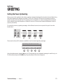
Soft Key:GREETNG ................................................................................................... 72
Soft Key: BACKLIT ..................................................................................................... 74
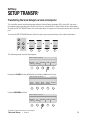
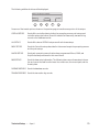
Soft Key: SETUP TRANSFR ..................................................................................... 77
Soft Key: RESET.......................................................................................................... 80
Soft Key: AUTO SWITCH ......................................................................................... 84
Soft Key: ALARMS ..................................................................................................... 86
Soft Key: DIG INP ...................................................................................................... 90
Soft Key: SETUP SECURTY ..................................................................................... 92
Soft Key: HYSTERS .................................................................................................... 94
Soft Key: APW QTY ................................................................................................... 96
Appendix A: RS232 Serial Port Communications ............................................................................99
Appendix B: ScriptcoderTM Custom Label Printing..........................................................................106
Appendix C: Battery Option ....................................................................................................................114
Appendix D: Strain Gauge Remote Scale Option ............................................................................116
Appendix E: Specifications ......................................................................................................................122
Appendix F: Glossary .................................................................................................................................125
Appendix G: Warranty ...............................................................................................................................127
Appendix H: Warnings ...............................................................................................................................128
FCC Warning .................................................................................................................................................129
EC Declaration of Conformity .................................................................................................................130
Index ................................................................................................................................................................131
Introduction
Introduction • Super II
4
Introduction
For many counting or weighing applications, the Super II default settings are adequate and the scale can
be used just as it comes from the factory. However, often the scale performance can be enhanced or
operation simplified if the factory settings are changed, or if some of the more specialized features are
enabled. This manual is designed to instruct the programmer in the procedures used to change factory
default settings for numerous scale features and, also, to describe how to use certain other features that
are not enabled at the factory. Access to these settings can be password protected to assure that the
settings, once programmed, are only changed by authorized personnel.
The manual is divided into four sections: Supervisor Setup, Technical Setup, Bases Setup and the appendices. Supervisor Setup, in general, allows application specific customization of the scale, such as programming the minimum sample size that will be allowed for counting certain parts, setting the baud rate for
communicating with a particular printer, changing the name of field identifiers that will appear on printed
labels and customizing prompts that will walk the user through a recurring counting or weighing transaction. Technical Setup allows customization of the scale that tends to be more related to scale performance,
as well as several other scale specific parameters. The Bases Setup section describes how to configure the
network of bases, including performance parameters. The fourth section consists of appendices that
explain, at length, how to use two standard features, RS232 data communications and the ScriptCoder
label making routine. It also describes the use of the optional battery and strain gauge remote scale option
which can be purchased separately.
This setups manual will enable customization and/or implementation of the following scale features:
Printing
Text and bar coded labels can be printed directly from the Super II controller using the optional Dymo®
SETRA 300 printer or the more advanced Eltron thermal printer (not available from Setra). ScriptCoder
allows easy interfacing to a wide variety of other printers and use of its powerful scripting language can
produce fairly complex labels, if needed.
Multiple Scale Systems
As described in the Bases Setup section of this manual, a single Super II scale can be converted into a
system consisting of one Super II controller connected to and operating up to eight separate bases. These
bases can be either Setra variable capacitance load cell bases or more conventional strain gauge load cell
bases, or a combination of both. This feature provides the advantage of integrating, at one workstation,
high resolution, low capacity bases for the optimal development of average piece weights, with low
resolution, high capacity bases for counting and weighing very large, bulky loads.
Internal Database
A flexible internal database can be used to store part numbers and associated data for up to 750 inventory
items. The ability to instantly recall an item‘s average piece weight from the database can eliminate repetitive sampling when that part is frequently counted. The ability to recall descriptive information from the
database reduces the need to input data when transaction receipts or other labels are generated.
Transaction Log
Resident in the scale’s database, this feature chronologically stores the results of each weighing or counting operation. The part number, the operator’s name, the time and date of the transaction and the quantity
counted can be automatically stored when the appropriate key is pressed. Transaction reports can be
periodically printed to help track material flow and reconcile inventory miscounts.
Introduction • Super II
5
Prompting Macros
The scale’s display can prompt a user through a series of steps for repetitive tasks. The macros are easily
written using this manual and the Super II controller. They can consist of up to 100 individual steps and
can be written in some foreign languages or industry jargon, if desired. The macros help to simplify scale
operation for novice or untrained operators by providing one-button operation.
Programmable Accuracy and Sample Size
This feature permits the programmer to make a trade-off between the sample size that is hand counted
onto the scale and the accuracy that the scale can potentially deliver. The higher the accuracy setting
selected, the larger the sample weight required. If the parts are small, a high accuracy setting can mean
that the scale will prompt an operator to hand count very large samples onto the scale. Hand counting
large samples can, in itself, introduce operator errors as well as slow down the scale counting process.
Hand counting very small samples (fewer than 5 pieces) may produce errors, since the average piece
weight may not be representative of the entire population of parts. The programmer uses these settings
to minimize errors introduced by nonuniform parts, hand counting or insufficient sample weight.
Programmable Units of Measure
A preprogrammed list of weighing units is available in the User Menu. This feature allows the programmer
to make several units available to the user, or only one unit if one is less likely to create confusion. Customized weighing units for special applications can be programmed and can be easily accessed by the user
when needed.
Setra Dialog Language (SDL) (New in Software Ver 3.01)
Setups, database records and transaction logs can be saved and restored using the Setra dialogue language.
A brief synopsis of the programming functions as they appear in the menu selections are listed below:
Supervisor Menu:
PRINT
SETUP
Program the interval print time period as well as the print formats for the 10 print
registers.
SAMPLE
SETUP
Program the minimum sample size, the sample size selections and to include a
sample size selection menu as part of your default operation.
ACCURCY
SETUP
Program the minimum scale performance accuracy based on the sample weight.
PORTS
SETUP
Program the baud rate and parity characteristics of the three serial ports.
TIME
DATE
Program the time and date and their reporting formats on power-up and when
printing.
UNITS
ENABLED
Select the availability of the various weighing units of measure as well as
program the user definable unit of measure.
DATBASE
SETUP
Select the Database fields for display, print the databases, and set the database
record protection.
Introduction • Super II
6
TRANSAC
SETUP
Activate and choose the fields to record in the transaction log, print the
transaction log or transfer to a computer, and clear the transaction log.
ID NAME
SETUP
Change the names of the ID fields.
MACRO
SETUP
Program up to ten macros (a series of scale operation steps) along with
customizable prompts.
SETUP
SECURTY
Program password protection for the Supervisor menus
BEEPER
Allows the beeper to be disabled.
CONTROL
Bases Menu:
CALIB
Perform a Span calibration and access the factory linearity calibration and test
menu.
UPDATE
SPEED
Select the filtering and update rate.
ZERO
TRACK
Set the level of Zero Tracking.
RESOLUT
Set the displayed weight resolution of the scale.
INFO
Display information about the bases such as display resolution, zero
tracking, sample resolution, and software revision.
NAME
Change the name of a base.
ADDRESS
Display and change the network address of the bases.
BASERST
Force the controller to evaluate the base network.
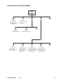
Technical Menu:
GREETNG
Change the greeting message on power-up.
BACKLIT
Set up the battery saving modes for the backlight option (if available).
SETUP
TRANSFR
Send setup and database information through the ports.
(Note: Available in Software Version 3.01.)
RESET
Return to the factory defaults and clear out separately the Database, Print
Registers, and Macros.
Program automatic switching options among multiple bases.
AUTO
SWITCH
Introduction • Super II
7
ALARMS
Configure and enable/disable the digital output alarms.
DIG INP
Set up the controller for control by outside equipment.
SETUP
SECURTY
Program password protection for the Technical and Bases Menu.
HYSTERS
Set up display hysteresis for more stable display.
APW QTY
Program the number of pieces by which the scale counts
Introduction • Super II
8
Supervisor Setup
Supervisor Setup • Super II
9
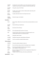
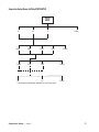
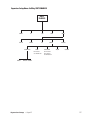
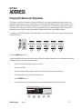
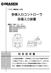
Supervisor Setup Menu: Soft Key PRINT
PRINT
SETUP
PRINT
FORMATS
PRINT
INTERVAL
GO BACK
Select Print Register:
0. PRINT 0
4. PRINT 4 8. PRINT 8
1. PRINT 1
5. PRINT 5 9. PRINT 9
2. PRINT 2 6. PRINT 6 -. Prt Int
3. PRINT 3
7. PRINT 7
Select Output Port:
BI
OUT
Select Output Format:
DYMO®/
COSTAR®
LABEL/PAPER
ELTRON®
SCRIPT
GO BACK
Enter label name Download “Script” or enter codes
as stored in printer through the front keypad QWERTY
keyboard, or barcode scanner
PORTRAIT/LANDSCAPE
Select the fields to print:
ID
TARE
APW
GO BACK
MORE
COUNT
GROSS
NET
GO BACK
MORE
ACCUMCT
ACCUMWT
ENTRIES
GO BACK
MORE
TIME
DATE
X (X of Y)
GO BACK
MORE
Y (X of Y)
LOW
TARGET
GO BACK
MORE
HIGH
SPL SIZE
LINEFEED
GO BACK
DONE
ID 0. PART ID
ID1. OPRTR
ID2. ORDER #
ID3. LOT #
Supervisor Setup • Super II
ID 4. DESC.
ID5. VENDOR
ID6. REV #
ID7.
ID8.
ID9.
10
Soft Key:
PRINT SETUP
Setting Print Formats or Print Interval
This setup allows for the design of up to ten different label formats, as well as, setting up the interval
printing function. There are three types of label formats available - the Dymo® SETRA 300 printer format,
the Eltron printer format, and Scriptcoder. Each of these formats is detailed below.
The Dymo® SETRA 300 has either “English only” or bar code and English information available for printing.
Straight ASCII text output is available by selecting “regular” size (vs. large print) which is compatible with
any serial dot matrix printer.
The Eltron printer selection is only designed to work in conjunction with a label format created using the
Eltron Create-A-Label software. The label format is stored in the printer’s memory. When an Eltron label is
printed, scale information is sent to the printer and combined with the label format in the printer.
For any other serial printer, a label design can be created using the ScriptCoder feature (see Appendix B for
details).
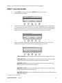
To access the PRINT SETUP menu, either follow the menu tree or press the soft keys in the order listed
below:
tare
menu
remote
MORE
abc
SETUPS
SUPER
SETUP
PRINT
SETUP
reset
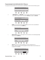
The soft keys will change to the following:
Select your print format # or special
instructions from the menu below:
PRINT
FORMATS
Supervisor Setup • Super II
PRINT
INTERVL
GO BACK
11
Select the function to program:
PRINT FORMATS allows the print registers to be configured.
.
PRINT INTRVL allows programming a time interval which, when elapsed, causes the scale to print
a selected format.
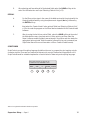
Programming a PRINT Format
Print Format Options: There are ten available formats that can be individually configured. Pressing the
PRINT FORMATS soft key described previously will access the Print register selection menu.
Select Print Register:
0. Print 0
4.
1. Print 1
5.
2. Print 2
6.
3. Print 3
7.
NAME
ON/OFF
Print 4
Print 5
Print 6
Print 7
8. Print 8
9. Print 9
–. Prt Int
DELETE # COPYS GO BACK
Select the NAME soft key to change the print format name (the title that appears in the above screen).
Select ON/OFF to enable and disable the print format. Disabled print formats cannot be printed but retain
their format information. Select # COPYS to program multiple label prints. Pressing # Copys will display the
following screen:
Enter number of copies to be printed or
VARIABL to select number at print time:
COPIES:
ENTER
VARIABL
GO BACK
Either enter the number of copies to be printed using the numeric keypad and press the ENTER soft key or
press the VARIABL soft key to allow the user to choose the number of copies when printing.
To program a print format, follow the steps below:
1.
Using the numeric keypad, select the desired print register to program
2.
Select the output port for the print format.
Select the port for the printer output.
BI
3.
OUT
GO BACK
Select the print format type:
Select your printer type:
DYMO ELTRON
COSTAR
Supervisor Setup • Super II
SCRIPT
GO BACK
12
Based on the print format type selected, one of three series of screens appears:
DYMO®* Setra 300/COSTAR
A.
Select LABEL (ends with form feed) or PAPER printing (sends a line of
dashes between printings).
Select your media type:
LABEL
B.
PAPER
GO BACK
Choose label orientation as either PORTRAIT which limits the bar coded ID information
to 9 characters when using the Setra control codes or LANDSCAPE which limits the bar
coded ID information to 20 characters when using the Setra control codes. (See RS232
Communications in Appendix A for more information on Setra control codes).
Select print orientation:
PRTRAIT
C.
LNDSCPE
GO BACK
Select a print field to appear on the label (see “Selecting Fields to Print”, p. 15). After
selecting a field to print, choose the output characteristics for that field.
Select the output for the field:
SMALL LARGE BARCODE BARCODE BARCODE
ENGLISH ENGLISH SC ENG SC LENG ENGLISH
SMALL ENGLISH is for the regular sized English text printing (straight ASCII text).
LARGE ENGLISH is for large English text printing (contains Dymo® control codes).
Large text has twice the height of the small text, but the same width.
BARCODE SC ENG is for a bar coded field with the Setra control characters (see
RS232 Appendix A) and regular size English
BARCODE SC LENG is for a bar coded field with the Setra control characters (see
RS232 Appendix A) and large English text.
BARCODE ENGLISH is for a bar coded field without the Setra control characters and
regular size English
* Trademark of Dymo® Corporation
Supervisor Setup • Super II
13
D.
After selecting and formatting all of the desired fields, select the DONE soft key at the
end of the field selection menu (see “Selecting Fields to Print”, p. 15).
ELTRON*
A.
For the Eltron printer, type in the name of the label as stored in the printer with the
Create-A-Label software by using the alphanumeric keypad (abc key) followed by
the ENTER soft key.
B.
Next select the Create-A-Label “when printed” fields (see “Selecting Fields to Print” ,
p. 15 in the order they appear on the Eltron label as created with the Create-A-Label
software.
C.
After choosing the last “when printed” field, select the DONE soft key at the end of
the field selection menu (see next section). When printing an Eltron label, the
Super II software recalls the label name as stored in the printer and then sends the
appropriate “when printed” field information followed by the print command (see
ScriptCoder Manual for more information on Eltron Create-A-Label formats).
SCRIPTCODER
ScriptCoder is a powerful scripting language that allows the user to program the print register a single
character at a time. There are four methods of data entry for a script. Please refer to Appendix B or the
ScriptCoder Manual for a detailed explanation of each method of data entry and scripting language.
Enter each character or code now. PC
to download script. BARCODE to scan.
ENTER
CODE
PC
BARCODE GO BACK
*Eltron® is a registered trademark of Zebra Corporation
Supervisor Setup • Super II
14
Selecting Fields to Print
The following is a list of all scale fields available for printing. The fields can be printed in any order selected. Move up and down through the menus by using the GO BACK and MORE keys.
Select the desired fields to print from the menu below:
ID
TARE
APW
GO BACK
MORE
COUNT
GROSS
NET
GO BACK
MORE
ACCUMCT
ACCUMWT
ENTRIES
GO BACK
MORE
(for an
accumulated
count)
(for an
accumulated
weight)
(will bring up all ID
fields listed below)
TIME
(for the number
of accumulated
entries)
DATE
X(X of Y)
GO BACK
MORE
Y (Xof Y)
LOW
TARGET
GO BACK
MORE
HIGH
SPLSIZE
LINEFED
GO BACK
DONE
(for the sample size
used to determine
the APW)
Supervisor Setup • Super II
(for spacing
between fields)
(to end
print format)
15
ID Fields
ID field selection will bring up the following menu.
Select ID Field:
IDØ: PART ID
ID1: OPRTR
ID2: ORDER #
ID3: LOT #
ID4: DESC
ID5: VENDOR
ID6: REV #
ID7:
ID8:
ID9:
GO BACK
Select the desired ID field to print by entering the numeric ID# associated with that field using the numeric
keypad.
The “identifier” associated with each field will print before the variable ID information as it appears in the
choices above for the Dymo® format. The identifier can be changed to any 7 characters desired.
To change the field identifier name, see the ID NAME soft key section starting on page 41.
NOTE: The database uses the IDØ field for storage indexing. It is recommended that the PART ID be
used for the IDØ field. LOT# (ID3) and DESC (ID4) correspond to the same scale ID locations as in
Setra’s AutoCount 200 for backward compatibility purposes.
Supervisor Setup • Super II
16
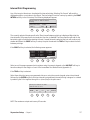
Interval Print Programming
Any of the ten print fomats can be selected for interval printing. Selecting “No Format” will send the
displayed weight or count value to the BI port. The interval print function is set up by selecting the PRINT
INTERVL soft key in the Print setup. The following display will appear:
Select Format or Time for Interval
Printing:
Interval Print Format: No Format
Interval Print Time:
0.0 SEC
PRINT
TIME
GO BACK
The currently selected format as well as the Time Interval between printings is displayed. Note that the
time interval of 0.0 means that the internal print function is disabled. The interval printer will wait for the
last printing job to finish before starting the next. If a small interval is selected, the port will continuously
stream data. Select the PRINT soft key to set up the print format and the TIME soft key to select the time
between printings.
If the PRINT soft key is selected, the following screen appears:
Select Format for Interval Printing:
0. Print 0
4. Print 4
8. Print 8
1. Print 1
5. Print 5
9. Print 9
2. Print 2
6. Print 6
–. Prt Int
3. Print 3
7. Print 7
NO FRMT
GO BACK
Select one of the preprogrammed print registers using the numeric keypad, or the NO FRMT soft key to
have the scale print the weight or count in the immediate Print Mode format. (Appendix A)
If the TIME soft key is selected:
Select from either the two pre-programmed choices or, using the numeric keypad, enter a time interval
followed by the ENTER key. Once the time interval is programmed, interval printing is stopped or started
by selecting the Prt Int register through the - (minus) key in the print menu.
Select print interval or enter
interval time (in sec.):
ENTER
OFF
0.2
0.5
GO BACK
NOTE: The maximum output rate is every 0.2 seconds.
Supervisor Setup • Super II
17
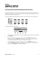
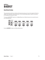
Supervisor Setup Menu: Soft Key SAMPLE SETUP
SAMPLE
SETUP
ENTER
Using the numeric keypad,
type in the desired minimum
sample size followed by
ENTER key
10
25
SAMPLE #
IN MENU
GO BACK
YES
NO
To have Sample Size menu
appear after SAMPLE key
is pressed.
50
100
GO BACK
Using the numeric
keypad, type in the
desired sample size
followed by the
soft key location
Supervisor Setup • Super II
18
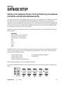
Soft Key:
SAMPLE SETUP
Setting a Minimum Sample Size/Sample Size Selection Menu
This setup allows a selection of a minimum number of pieces that can be used to generate an APW. Also
available is the capability to have the scale create a prompt for multiple sample size selections that can be
customized to whatever the operator needs.
To access the SAMPLE menu, either follow the menu tree or press the soft keys in the order listed below:
tare
menu
remote
MORE
abc
SETUPS
SUPER
SETUP
SAMPLE
SETUP
reset
The soft keys will change to the following:
Type in the minimum sample size or choose
from the options below.
MIN. SAMPLE:
ENTER SAMPLE # IN MENU
1
GO BACK
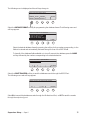
1.
To set the minimum sample size, use the numeric keypad and type in the desired number followed
by the ENTER key.
2.
To change the sample size in the series of prompts when the LRG SPL key is pressed in the
default user menu, choose SAMPLE #. Change each prompt to any desired value by using the
numeric keypad followed by the soft key for the number to be changed.
3.
To have sample size choices appear in the main menu when the SAMPLE > key is pressed,
choose the IN MENU key followed by the YES key. The “sample size menu” choice can be turned
off by pressing the IN MENU key followed by the NO key.
Supervisor Setup • Super II
19
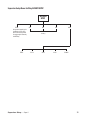
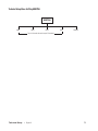
Supervisor Setup Menu: Soft Key ACCURCY SETUP
ACCURACY
SETUP
ENTER
Using numeric keypad, type in
the desired minimum scale
performance accuracy based
on sample weight followed by
the ENTER key
95%
ENTER
Supervisor Setup • Super II
98%
99%
MORE
Selected
accuracy
99.5%
99.8%
99.9%
GO BACK
20
Soft Key:
ACCURCY SETUP
Setting a Minimum Scale Performance Accuracy
This setup allows selection of the minimum accuracy level to which the scale will perform based on the
sample weight. The higher the scale performance, the larger the sample weight required. This may cause
the scale to prompt for additional pieces when the COUNT key is pressed to meet the minimum weight
requirement to perform to the programmed accuracy level.
IMPORTANT: This setup does not take individual piece weight variance into account and only has to do
with sample weight. The scale must also be programmed with a large enough minimum sample size to
guarantee performance based on piece weight variance.
To access the ACCURACY menu, either follow the menu tree or press the soft keys in the order listed below:
tare
menu
remote
MORE
abc
ACCURCY
SETUP
SUPER
SETUP
SETUPS
reset
Using the numeric keypad, type in the desired Minimum Scale Performance Accuracy followed by the
ENTER key or choose from the soft key selections available and listed below.
Enter the minimum scale performance
accuracy or select from the menu below:
ACCURACY
ENTER
95%
95.00
98%
99%
MORE
Additional selections are available by pressing the MORE soft key.
Enter the minimum scale performance
accuracy or select from the menu below:
ENTER
99.5%
99.8%
99.9%
GO BACK
Either type in the desired Minimum Scale Performance Accuracy followed by the ENTER soft key or choose
from the selections available.
Supervisor Setup • Super II
21
Supervisor Setup Menu: Soft Key PORTS SETUP
PORTS
SETUP
BI*
B9600
8 NONE
OUT
IN
GO BACK
B4800
B2400
7 ODD
7 EVEN
GO BACK
OFF
GO BACK
ON
B1200
GO BACK
* Hardware handshaking available on the BI port only
Supervisor Setup • Super II
22
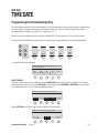
Soft Key:
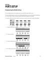
PORTS SETUP
Programming the RS232 Settings
This setup allows selection of the settings for the three RS232 communication ports.
The factory default setting for the BI port is 9600 baud, 8 databits, no parity with hardware handshaking
on. For the IN and OUT ports, the factory default is 2400 baud, 8 databits, and no parity.
To access the RS232 menu, either follow the menu tree or press the soft keys in the order listed below:
tare
menu
remote
MORE
abc
SUPER
SETUP
SETUPS
PORTS
SETUP
reset
1. Choose the RS232 port to configure.
Select the port to configure:
BI
OUT
IN
GO BACK
2. Choose the baud rate.
Select the baud rate:
B9600 B4800 B2400 B1200 GO BACK
3. Choose the databit/parity setting.
Select the character format/byte size:
Note: IN & OUT ports share a common byte
8NONE
7ODD
7EVEN
GO BACK
4. For the BI port only, choose to have hardware handshaking ON or OFF.
Select enabling of hardware handshaking:
ON
Supervisor Setup • Super II
OFF
GO BACK
23
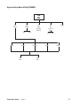
Supervisor Setup Menu: Soft Key TIME DATE
TIME
DATE
DATE
FORMAT
TIME
FORMAT
12 HR
ENGLISH
US NUM
2 DIGIT
YEAR
Supervisor Setup • Super II
SET
DATE
Enter date
MM.DD.YY
24 HR
SET
TIME
Enter time
HH.MM
GO BACK
AM PM 24 HR
EUR NUM
MILITARY
SET DIG
4 DIGIT
YEAR
24
Soft Key:
TIME DATE
Programming the Time Date Reporting
This setup allows setting of the time and date for the scale as well as choosing the format for reporting the
time and date. For example, time can be reported in either 12 or 24 hour format and the year can be
reported as either 4 digits (e.g., “2001”) or 2 digits (e.g. , “01”)
Note: The factory default reports the date in US MM/DD/YYYY and the hour in 12 hour time format.
To access the TIME DATE menu, either follow the menu tree or press the keys in the order listed below.
tare
menu
remote
MORE
abc
SUPER
SETUP
SETUPS
MORE
TIME
DATE
reset
Choose from the options below:
Select from the options below to set up
the time and date:
DATE
FORMAT
TIME
FORMAT
SET
DATE
SET
TIME
GO BACK
DATE FORMAT
The date can be printed in four different formats. ENGLISH spells out the month in English. The numeric
date reporting can be in U.S. format (US NUM) or European format (EUR NUM). MILITRY reports the date
in the military format. Choose from the available options:
Choose the print format for the month:
ENGLISH US NUM
EUR NUM
MILITRY
SET DIG
Select (SET DIG) to print the year in either 2 digit or 4 digit format.
Choose the print format for the year:
2 DIGIT
Supervisor Setup • Super II
4 DIGIT
GO BACK
25
TIME FORMAT
The time can be printed in either 12 hour or 24 hour format. Choose from the options below:
Select the display format for the time.
12 HR
24 HR
GO BACK
SET DATE
Using the numeric keypad, type in the date in the format, MM.DD.YY, followed by the ENTER key:
Set the date using the format MM.DD.YY
ENTER
GO BACK
SET TIME
Using the numeric keypad, type in the time in the format, HH.MM, followed by a selection for AM, PM, or
24 HR key.
Set the time using the format HH.MM
AM
Supervisor Setup • Super II
PM
24 HR
GO BACK
26
Supervisor Setup Menu: Soft Key UNITS ENABLED
UNITS
ENABLED
GRAMS
TROY OZ
OZ
LBS
CARATS
CONVERSION
KG
NAME
Enter name for
user definable unit
FACTOR
DWT
MORE
GRAINS
RESOLUTION
GO BACK
ON/OFF
GO BACK
Enter resolution
for last digit for
user definable unit
DIVISOR GO BACK
Supervisor Setup • Super II
27
Soft Key:
UNITS ENABLED
Selecting Weighing Units
This setup allows selection of units of measure available in the UNITS soft key menu in the User Functions
(See User’s Manual). In addition, the last unit of measure (GRAINS) is a user definable unit of measure,
sometimes referred to as ‘x’units. For the user definable unit, the conversion factor, the resolution and the
name of the unit can be customized.
Note: The factory default is to have all units available and the user definable unit set to GRAINS.
To access the UNITS ENABLED menu, either follow the menu tree or press the keys in the order listed
below:
GRAMS
tare
menu
remote
MORE
abc
1.
SUPER
SETUP
SETUPS
MORE
UNITS
ENABLED
reset
To toggle the availability of a unit of measure, select that unit of measure. Units that are not available to the
user are shown in reverse video.
Enable/Disable units or Program
x units. Select from the menu below:
GRAMS
OZ
LBS
DWT
MORE
Enable/Disable units or Program
x units. Select from the menu below:
TROY OZ
Supervisor Setup • Super II
CARATS
KG
GRAINS GO BACK
28
Programming the User Definable Unit of Measure
To program the user definable unit, choose the last unit (GRAINS) then select from the following menu:
Enter the details of the selected unit:
CONVRSN NAME RESOLUT ON/OFF GO BACK
a.
CONVERSION: Press CONVRSN and then, using the scale keypad, enter the conversion number for grams; then choose either FACTOR (multiplier) or DIVISOR.
Enter the conversion factor (x) or
divisor (/) from grams:
FACTOR DIVISOR
b.
GO BACK
NAME: Using the alphanumeric keypad (abc key), enter the unit name (limited to
six characters) followed by the ENTER key.
Enter the unit name:
ENTER
c.
GO BACK
RESOLUTION: Using the scale keypad, enter the resolution of the last displayed digit
followed by the ENTER key.
Enter the resolution of the last digit:
ENTER
d.
GO BACK
ON/OFF: This key turns off the availability of the User Definable Unit of
Measure. When the ON/OFF soft key appears in reverse video, the user definable unit
of measure is unavailable.
Enter the details of the selected unit:
CONVRSN NAME RESOLUT ON/OFF GO
Supervisor Setup • Super II
29
Supervisor Setup Menu: Soft Key DATBASE SETUP
DATABASE
SETUP
DATBASE
FORMAT
PRINT
TRANSFR
BI
DATBASE
SECURTY
OUT
GO BACK
LOCKOLD
1
PART ID, APW, TARE
2
PART ID, LOT #, APW
5
FULL DATABASE
Supervisor Setup • Super II
GO BACK
NO LOCK
3
PART ID, APW, ACC CT
6
DATABASE OFF
LOCKALL
4
PART ID, LOW, TARGET, HIGH
GO BACK
MORE
GO BACK
30
Soft Key:
DATBASE SETUP
Setting up the Database Format, Printing/Transferring the Database
Information, and Setting the Database Security
The controller has memory for a database which has a number of configurations. The database can contain
two different types of records: database records and transactions. Database records contain stocking
information and can be recalled using the PART ID (IDØ). Transactions are stored and accessed sequentially
and each contains information about a single event or action performed on a single part. The database can
hold up to 750 records in any combination of database records and/or transactions. See TRANSAC SETUP
for details about Transaction log records and setups.
Database records and transactions are made up of fields of information. The records are comprised of the
following fields:
DATABASE:
PART ID (IDØ): (up to 23 characters)
DESC (ID4): (up to 16 characters)
LOT #(ID3): (up to 16 characters)
APW
Tare:
Count:
Low:
Target:
High:
The PART ID (IDØ) is used to index database records. When entering records into the database, the PART ID
(IDØ) must be non-empty and unique. The database is configurable to a user’s needs. The five database
setups and the disabling option are:
1. Part ID, APW, and Tare
2. Part ID, Lot#, and APW
3. Part ID, APW, and Count
4. Part ID, Low, Target, High (Setpoints)
5. Full Database (All fields available)
6. Database off
Note: The factory default is to have the database turned off.
To access the DATBASE SETUP menu, either follow the menu tree or press the soft keys in the order listed
below:
tare
menu
remote
MORE
abc
SETUPS
SUPER
SETUP
MORE
DATBASE
SETUP
reset
Supervisor Setup • Super II
31
The following menu is displayed and the soft keys change to:
Select database setup option:
DATBASE PRINT DATBASE
FORMAT TRANSFR SECURTY
GO BACK
Select the DATBASE FORMAT soft key for programming the database format. The following menu and
soft keys appear:
Choose the fields in the database:
1. PART ID, APW, TARE
2. PART ID, LOT #, and APW
3. PART ID, APW, ACC CT
4. PART ID, LOW, TARGET, HIGH
1
2
3
4
MORE
Select the desired database format by pressing the soft key for the number corresponding to the
fields to be stored and automatically retrieved through the use of the PART ID field.
To have all of the database fields available or to turn off access to the database, press the MORE
soft key followed by the number corresponding to the desired selection:
C hoose the fields in your database:
5. FULL DATABASE
6. DATABASE OFF
5
6
GO BACK
Select the PRINT TRANSFER soft key to send the database records through the RS-232 Port.
The following menu and soft keys appear:
Select the port for the printer output.
BI
OUT
GO BACK
Select BI to transmit the database records through the Bi-directional Port, or OUT to send the records
through the output only port.
Supervisor Setup • Super II
32
Select DATABASE SECURTY to change the user access to the database records.
Select type of record, transaction log,
or database
DATBASE PRINT DATBASE
FORMAT TRANSFR SECURTY
GO BACK
The following menu and soft keys will appear:
Select the database protection from the
menu below:
LOCK OLD NO LOCK LOCK ALL
GO BACK
LOCK OLD: Prevents a user from making any changes or deletions to a saved record in the
database. However, new records can be added to the database.
NO LOCK:
Allows full access to the database for changes, deletions and additions.
(Default)
LOCK ALL:
Prevents any changes, deletions and additions to the database.
Supervisor Setup • Super II
33
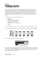
Supervisor Setup Menu: Soft Key TRANSAC SETUP
TRANSAC
SETUP
TURN TL
ON/OFF
CHOOSE
FIELD 4
PRINT
TRANSFER
CLEAR
TL
YES
ID0:
ID1:
ID2:
ID3:
ID4:
ID5:
ID6:
ID7:
Supervisor Setup • Super II
NO
GO BACK
GO BACK
ID8:
ID9:
BI
OUT
GO BACK
STANDRD
TAB
COMMA
34
Soft Key:
TRANSAC SETUP
The controller has memory for an extensive database which has a number of configurations. The
database can contain two different types of records: database records and transactions. Database
records contain stocking information and can be recalled using the PART ID (IDØ). Transactions are
stored and accessed sequentially and each contains information about a single event or action
performed on a single part. The database can hold up to 750 records in any combination of database
records and/or transactions. See DATBASE SETUP for details about setting and using database
records.
Transactions can contain up to six fields of information:
TL RECORD:
PART ID (IDØ): (up to 23 characters)
LOT # (ID3): (up to 16 characters)
DESC (ID4): (up to 16 characters)
User Selectable ID: (up to 16 characters)
Count:
Time/Date:
Any of the fields may be enabled or disabled. A disabled field will not be stored, displayed or printed.
To access the TRANSAC SETUP menu, either follow the menu tree or press the keys in the order below:
tare
menu
remote
MORE
abc
SETUPS
SUPER
SETUP
MORE
TRANSAC
SETUP
reset
The following menu appears and the soft keys change to:
Select TL fields using the numeric keys:
1. PART ID
2. LOT #
3. DESC.
TURN TL
ON/OFF
4. OPRTR
5. COUNT
6. TIME/DATE
CHOOSE PRINT
CLEAR
FIELD 4 TRANSFR
TL
GO BACK
The Transaction Log will make a record of any combination of the above fields. To choose which fields
will be recorded each time the SAVE key in the User menu is pressed, simply select the field using the
numeric keypad. Selected fields will appear with the light background whereas fields not chosen will
be in reverse video with a dark background.
Supervisor Setup • Super II
35
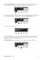
Select the TURN TL ON/OFF soft key to activiate the Transaction Log. When the Transaction Log is off,
access to the saving, viewing, and printing screens are disabled but the format is retained.
Select TL fields using the numeric keys:
1. PART ID
2. LOT #
3. DESC.
TURN TL
ON/OFF
4. OPRTR
5. COUNT
6. TIME/DATE
CHOOSE PRINT
CLEAR
FIELD 4 TRANSFR
TL
GO BACK
Selection #4 is a user definable ID field. The default choice is the OPRTR (ID1) field, but can be changed to
any of the available ID registers. To change Selection #4, press the CHOOSE /FIELD 4 soft key.
Select TL fields using the numeric keys:
1. PART ID
2. LOT #
3. DESC.
TURN TL
ON/OFF
4. OPRTR
5. COUNT
6. TIME/DATE
CHOOSE PRINT
CLEAR
FIELD 4 TRANSFR
TL
GO BACK
The ID selection menu will then appear:
Select the extra Tl field:
IDØ: PART ID ID4: DESC
ID1: OPRTR
ID5: VENDOR
ID2: ORDER # ID6: REV #
ID3: LOT #
ID7:
ID8:
ID9:
GO BACK
To activate the desired ID field for the Transaction Log, simply use the numeric keypad and enter the
number for that ID field. The selected ID will appear with the light background whereas the other IDs
will appear in reverse video with a dark background.
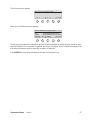
Press PRINT TRANSFR to send the Transactions stored in the Transaction Log to an RS232 port.
Select TL fields using the numeric keys:
1. PART ID
2. LOT #
3. DESC.
TURN TL
ON
Supervisor Setup • Super II
4. OPRTR
5. COUNT
6. TIME/DATE
CHOOSE PRINT
CLEAR
FIELD 4 TRANSFR
TL
GO BACK
36
The following menu appears:
Select the Port for Printer output:
BI
IN
GO BACK
Select a port. The following menu appears:
Select a Transaction Log Print format:
STANDRD - Standard log listing
TAB
- Tab delimited data file format
COMMA
- Comma delimited data file format
STANDRD TAB
COMMA
GO BACK
Choose a print format and the data will be printed. Note that standard log listing will print a label for each
record and field which is convenient for printed reports but of marginal use for computer data capture. Tab
and comma formats are used for exporting the data to a computer.
Press CLEAR TL to erase all the transactions stored in the Transaction Log.
Supervisor Setup • Super II
37
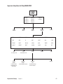
Supervisor Setup Menu: Soft Key ID NAME SETUP
ID NAME
SETUP
ID0: PART ID
ID1: OPRTR
ID2: ORDER #
ID3: LOT #
ID4: DESC
ID5: VENDOR
ID6: REV #
ID7:
ID8:
ID9:
GO BACK
Supervisor Setup • Super II
38
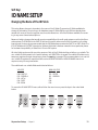
Soft Key:
ID NAME SETUP
Changing the Name of the ID Fields
This setup allows changes to be made to the name of the ID fields. There are ten ID fields available for
storage of information, for printing or for database usage. ID fields IDØ through ID6 have already been
named with some of the most popular uses for scale transactions. All of the fields are available for renaming to any seven character descriptions.
Beware of making changes that would cause incompatibility with multi-scale systems or with older Setra
scale systems. The IDØ field is the PART ID field and is used to reference all of the information in the database records. It is strongly recommended that the IDØ field always remains the PART ID or PART # field. The
ID3: LOT# field and ID4: DESC (description) field are fields that have been named in those particular places
for backward compatibility to Setra’s Auto CountTM200 system.
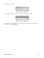
All other fields can be used for any other purpose. Each of the ID fields is either volatile or non-volatile. The
non-volatile ID fields remain in the scale’s memory until DELETED or changed. The volatile ID fields are only
temporary registers that get cleared every time the reset key is pressed. The recommendation is to use the
non-volatile ID registers for repetitive fields such as OPERATOR NAME or VENDOR NAME that do not
require re-entry for every transaction.
The volatile and non-volatile fields are divided as follows:
VOLATILE
NON-VOLATILE
IDØ:
ID2:
ID3:
ID4:
ID6:
ID1: OPRTR
D5: VENDOR
ID7:
ID8:
ID9:
PART ID
ORDER #
LOT #
DESC
REV#
To access the ID NAME SETUP menu, either follow the menu tree or press the keys in the order listed
below.
tare
menu
remote
MORE
abc
SETUPS
SUPER
SETUP
MORE
MORE
ID NAME
SETUP
reset
Supervisor Setup • Super II
39
The following menu will appear:
Select ID Field to Name:
IDØ: PART ID ID4: DESC
ID1: OPRTR
ID5: VENDOR
ID2: ORDER # ID6: REV #
ID3: LOT #
ID7:
ID8:
ID9:
GO BACK
Using the numeric keypad, enter the number of the desired ID field name to be changed.
E nt e r new name, followed by the Enter.
ENTER
GO BACK
Using the alphanumeric keypad (abc key) or PC keyboard, enter up to 7 characters of the new name for
the ID field followed by the ENTER soft key.
Supervisor Setup • Super II
40
Supervisor Setup Menu: Soft Key MACRO SETUP
MACRO
SETUP
0. Macro
1. Macro 1
2. Macro 2
3. Macro 3
NAME/
RENAME
MACRO
ON/OFF
4. Macro 4
5. Macro 5
6. Macro 6
7. Macro 2
8. Macro 8
9. Example
DELETE
FORMAT
PROGRAM
MACRO
GO BACK
ZERO
COUNT
CLEAR
PRINT
ADD CT
SET PTS
X UNIT
TARE
APW
ID
NEXT
SUB CT
LOW
Y UNIT
TARE WT
END CT
RECL DB
ACCUM
BASE
TARGET
UNITS
SAMP/CT
RESTART
RESET
SAVE DB
SAVE TL
HIGH
EXIT
PREV
to move up in list
CUSTOM
PROMPT
to write and use a
new prompt up to
80 characters
NEXT
to move down in list
STANDARD
PROMPT
to use the default prompt
Supervisor Setup • Super II
SELECT
AUTOMATE
STEP
to automate the step
without a prompt
GO BACK
DONE
GO BACK
41
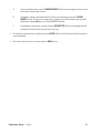
Soft Key:
MACRO SETUP
Customizing Scale Operation & Prompting Sequences
This setup allows creation of a custom scale operation sequence. A macro step can either use the standard
prompt or a custom prompt. The prompts are limited to 80 characters on two lines. The scale function
names cannot be changed.
Each macro is comprised of a series of steps. A step has an operation that the scale performs (selectable
from a list during macro programming) and a prompt to the user.
There are two modes of operation of the macro:
1.
2.
If only Macro Ø is enabled, it will be the scale’s DEFAULT as the first and only operation available on
power-up, using the soft keys (except for going into the menu system).
If macros other than Macro Ø ‚ are enabled, they will be available when the MACRO SETUP soft
key is pressed while in the scale’s normal default operating mode. If more than one macro is
enabled, a menu selection will appear.
To access the MACRO SETUP menu either follow the menu tree or press the keys in the order listed below:
tare
menu
remote
MORE
abc
SETUPS
SUPER
SETUP
MORE
MORE
MACRO
SETUP
reset
The following menu appears:
Select the Macro script to edit:
0. Macro 0
4. Macro 4
1. Macro 1
5. Macro 5
2. Macro 2
6. Macro 6
3. Macro 3
7. Macro 7
8. Macro 8
9. EXAMPLE
GO BACK
Using the numeric keypad, select the Macro (Ø-9) to edit. If the macro is to be the scale’s DEFAULT, place it
in Macro Ø. Please note that if Macro Ø is the only macro active, it will automatically become the scale’s
default operation. If only one macro is programmed and it is not to become the scale’s default operation,
place it in Macro 1 - 9.
Supervisor Setup • Super II
42
Once the macro position has been selected, the soft keys change to the following:
Enter or change the prompt format name,
set activation status or delete existing:
NAME/ MACRO DELETE PROGRAM GO BACK
RENAME ON/OFF FORMAT MACRO
NAME/RENAME
To customize the name of a Macro (up to 7 characters) and help
identify its function when it appears in the Macro Selection Menu.
Some possible examples are RECEIVE for a receiving function or KIT#123
for a special bagging operation.
MACRO ON/OFF
To turn on or to turn off access to the Macro.
DELETE FORMAT
To delete the programmed steps in the Macro.
PROGRAM MACRO
To select the steps for the Macro.
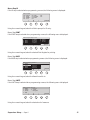
Programming a Macro
1.
After selecting the PROGRAM MACRO soft key in the previous menu, the top of the long list of
possible scale functions appears with the following soft keys:
Select the next step for the Macro:
Z ERO
Zeros any weight on the scale
TARE
Subtracts container weight
TARE WT Allows numeric tare wt entry
SAMP/CT Determines APW based on sample
PREV
NEXT
SELECT
DELETE
DONE
2.
To scroll through the list of scale functions, use the PREV(previous) and NEXT soft keys. The list of scale
functions is on the following pages.
3.
To select the highlighted scale function as the next step in the macro, press the SELECT soft key. The default
prompt associated with that key name and function will appear and the soft keys change to the following:
Select custom prompt, standard prompt,
or Automate step without prompt
Zero the scale by pressing the ZERO key
CUSTOM STANDRD AUTOMAT
PROMPT PROMPT
STEP
Supervisor Setup • Super II
GO BACK
43
A.
To use the default prompt, press the STANDRD PROMPT soft key and the program will return to the
scale function selection menu (step 1).
B.
To program a custom prompt associated with that key name and function, press the CUSTOM
PROMPT soft key. The menu will change; type in a prompt of up to 80 characters using the scale’s
alphanumeric keypad (abc key) or an attached QWERTY keyboard.
C.
To automate the step without a prompt, press the AUTOMAT STEP soft key. An automated step will
process the scale function without waiting for user input.
4. To erase the last selected step in the macro, press the DELETE soft key. If all the steps are erased, the previous
screen is displayed.
5. After selecting the last step in the macro, press the DONE soft key.
Supervisor Setup • Super II
44
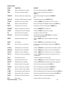
MACRO STEPS:
NAME
FUNCTION
PROMPT
ZERO
Zeros any weight on the scale
Zero the scale by pressing the ZERO key.
TARE
Subtracts container weight
Place an empty container and press the
TARE key.
TARE WT
Allows numeric tare weight entry
Enter the tare weight and press the TARE WT
key.
SMPL/CT
Determines APW based on sample
Add sample and press the SMPL/CT key.
COUNT
Switches to the count mode
Press the COUNT key to switch to the count mode.
APW
Allows numeric APW entry
Enter the Average Piece Weight and press the APW key.
ENDCT
Prompts to end counting
Add pieces until done and press the ENDCT key.
RESTART
Returns to beginning of macro
Press the RESTART key to start over.
CLEAR
Changes from Count to Weight
Press the CLEAR key to return to weight.
ID
Enters data into ID register
Prompts for selected ID field.
RECL DB
Recalls record from database
Enter ID # and press the RECL DB key to recall the
record from the database.
RESET
Clears all and resets macro
Press the RESET key to clear all registers and begin
again.
PRINT
Prints labels
Press the PRINT key. (For selected print format)
NEXT
Entry for any non-scale step
Do your non-scale related step and press the NEXT key
to continue.
ACCUM
Adds display to accumulator
Press the ACCUM key to add to the Accumulator register.
SAVE DB
Saves the record to database
Press the SAVE key to save the record to the database.
ADD CT
Adds the count to database
Press the ADD CT key to add the count to the database.
SUB CT
Subtracts count from database
Press the SUB CT key to subtract the scale count from
the database.
BASE
Switches active base
Prompts to switch to selected base.
SAVE TL
Saves a transaction record
Press the SAVE TL key to enter a Transaction Log record.
SET PTS
Displays set point registers
Press the SET PTS key to display the sets point registers.
LOW
Enters number in low register
Enter the low limit and press the LOW Key.
TARGET
Enters number into the target
Enter the target limit and press theTARGET key.
HIGH
Enters number in high register
Enter the high limit and press the HIGH Key.
X UNIT
Enters beginning # in sequence
Enter the beginning # of the series and press the X UNIT key.
Y UNIT
Enters ending # in a sequence
Enter the ending # of the series and press the Y UNIT key.
UNITS
Switches units for active base
Prompts to switch to selected weighing unit.
EXIT
Exits macro
Supervisor Setup • Super II
Press the exit key to end the Macro.
45
Macro Step ID
If the ID step is selected when programming a macro, the following menu is displayed:
Select ID Field:
IDØ: PART ID
ID1: OPRTR
ID2: ORDER #
ID3: LOT #
ID4: DESC
ID5: VENDOR
ID6: REV #
ID7:
ID8:
ID9:
GO BACK
Using the numeric keypad, select the field to prompt for ID entry.
Macro Step PRINT
If the PRINT step is selected when programming a macro, the following menu is displayed:
Select the print setup to use:
0. Print 0
4. Print 4
1. Print 1
5. Print 5
2. Print 2
6. Print 6
3. Print 3
7. Print 7
8. Print 8
9 . Print 9
–. Prt Int
GO BACK
Using the numeric keypad, select the desired Print Register for printing.
Macro Step BASE
If the BASE step is selected when programming a macro, the following menu is displayed:
Select the base to switch to.
1. Base 1
5. Base 5
2. Base 2
6. Base 6
3. Base 3
7. Base 7
4. Base 4
8. Base 8
GO BACK
Using the numeric keypad, select the Base # to switch to.
Macro Step UNITS
If the UNITS step is selected when programming a macro, the following menu is displayed.
Select Units to switch to:
1. Grams
5. Troy Oz
2. Ounces
6. Carats
3. Pounds
7. Kilograms
4. DWT
GO BACK
Using the numeric keypad, select the desired unit of measure.
Supervisor Setup • Super II
46
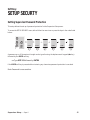
Supervisor Setup Menu: Soft Key SETUP SECURTY
SETUP
SECURITY
ENTER
Supervisor Setup • Super II
GO BACK
47
Soft Key:
SETUP SECURTY
Setting Supervisor Password Protection
This setup allows the set up of password protection for the Supervisor Setup menu.
To access the SETUP SECURITY menu, either follow the menu tree or press the keys in the order listed
below:
tare
menu
remote
MORE
abc
SETUPS
SUPER
SETUP
MORE
MORE
SETUP
SECURTY
reset
A password up to 10 characters in length can be typed in using the alphanumeric keypad (abc key)
followed by the ENTER soft key.
ex: Type XYZ 123 followed by ENTER
If the ENTER soft key is pressed without entering any characters, password protection is canceled.
Note: Password is case sensitive.
Supervisor Setup • Super II
48
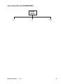
Supervisor Setup Menu: Soft Key BEEPER CONTROL
BEEPER
CONTROL
ON
Supervisor Setup • Super II
OFF
GO BACK
49
Soft Key:
BEEPER CONTROL
Setting the Beeper to ON and OFF
To access the Beeper Control menu, either follow the menu tree or press the keys in the order listed below:
tare
menu
remote
MORE
abc
SETUPS
SUPER
SETUP
MORE
MORE
MORE
BEEPER
CONTROL
reset
The following menu appears:
Select if Beeper is enabled:
ON
OFF
GO BACK
Select the ON soft key to enable the beeper and the OFF to disable the beeper.
Supervisor Setup • Super II
50
Bases Setup
Bases Setup
•
Super II
51
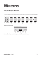
Bases Setup Menu: Soft Key CALIB
1. BASE 1
2. BASE 2
3. BASE 3
4. BASE 4
5. BASE 5
6. BASE 6
7. BASE 7
8. BASE 8
CALIB
ZERO
Zero scale,
recommended
first step
ENTER
User defined weight
SPAN
BASECOM
50 %
100 %
Scale calculated weights
GO BACK
GO BACK
SPAN
Bases Setup
•
Super II
52
Soft Key:
CALIB
Calibration
There are two types of calibration available. The most common type of calibration is referred to as a span
calibration which is a single point readjustment of the calibration curve to a known weight value. The scale
MUST be span calibrated when first installed to compensate for gravity differences between the point of
manufacture and the point of installation. The second type of calibration is called a linearity adjustment.
Multiple weight values are assigned to the calibration curve using several calibration weights.
The scale can be span calibrated as often as desired. A linearity calibration should only be necessary if the
scale is out of tolerance (non-linear) after a span calibration has been performed. Frequency of calibration
is dependent on many factors such as use of the scale, changes in the environment surrounding the scale
and accuracy goals. Consult your local scale dealer for a calibration schedule.
To access the CALIBRATION selection in the Bases Setup menu, follow the menu tree or press the keys in
the order listed below:
tare
menu
remote
MORE
abc
BASES
SETUP
SETUPS
CALIB
reset
Press the CALIB soft key.
Before beginning either calibration procedure, the scale should always be level and in the weighing units
of the calibration weight(s). Without anything on the pan, press the ZERO soft key and the message “Zero
Base Process Activated” should appear on the top line.
SPAN Calibration
1.
Press the SPAN soft key to enter the span calibration menu.
Select calibration option:
ZERO
Bases Setup
•
Super II
0.00
SPAN BASECOM
Base 1
Grams
GO BACK
53
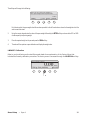
The soft keys will change to the following:
Select the % of full-scale weight or
enter Span weight value and press enter:
ENTER
50%
100%
Grams
GO BACK
For the best results, the span weight should be as close as possible to the full-scale value or closest to the weight at which the
scale is most often used.
2.
Using the numeric keypad, enter the value of the span weight followed by the ENTER soft key or choose either 50% or 100%
of scale capacity for spanning weight.
3.
Place the required weight on the pan and press the SPAN soft key.
4.
The scale will then perform a span calibration and display the weight value.
LINEARITY Calibration
Refer to your local factory authorized Setra scale dealer for an explanation of the Factory Menu that
includes the linearity calibration procedure. The factory menu is accessed through the BASECOM soft key.
Select calibration option:
ZERO
Bases Setup
•
Super II
0.00
SPAN BASECOM
Base 1
Grams
GO BACK
54
Bases Setup
•
Super II
55
Bases Setup Menu: Soft Key SPEED
1. BASE 1
2. BASE 2
3. BASE 3
4. BASE 4
5. BASE 5
6. BASE 6
7. BASE 7
8. BASE 8
SPEED
FASTEST
Bases Setup
•
FAST
Super II
DEFAULT
SLOW
SLOWEST
56
Soft Key:
SPEED
Setting the Display Update Rate (Speed of Change for the Display)
Depending on the environment or application for the scale, it may be necessary to change the rate at
which the display responds to changes on the platter. For some filling applications, it may be helpful to put
the scale into a fast update rate to prevent overshooting a target. Conversely, for environments with draft
or vibration, a slower update rate may provide greater stability. It may be necessary to make a trade-off
between stability and update rate.
To access the SPEED setting in the Bases Setup menu, follow the menu tree or press the keys in the order
tare
menu
remote
MORE
abc
SETUPS
BASES
SETUP
SPEED
reset
Press the SPEED soft key.
Simply choose the desired update rate by pressing the corresponding soft key.
Bases Setup
•
Super II
57
Bases Setup Menu: Soft Key ZERO
1. BASE 1
2. BASE 2
3. BASE 3
4. BASE 4
5. BASE 5
6. BASE 6
7. BASE 7
8. BASE 8
ZERO
ENTER
Customize
amount of
zero tracking
Bases Setup
•
0.5 DIV
Super II
1 DIV
Popular zero tracking choices
2 DIV
NONE
Turn zero
tracking off
58
Soft Key:
ZERO
Setting the Level of Zero Tracking
The scale is programmed with a level of zero tracking designed to help the scale maintain zero weight in a
normal operating setting. Zero tracking works by rejecting very small changes in weight as “noise” and
keeping the display on zero. For certain applications, such as monitoring slow flow rates, zero tracking can
be turned off. On the other hand, in “bad” or “noisy” environments, zero tracking can be increased to help
the scale maintain zero weight when nothing is added to it.
To access the ZERO setting in the Bases Setup menu, follow the menu tree or press the keys in the order listed
below:
tare
menu
remote
MORE
abc
SETUPS
BASES
SETUP
ZERO
reset
To enter a level of zero tracking, use the numeric keypad followed by the ENTER soft key or choose from
the available options. A scale division is the smallest increment that the display is set to detect. The factory
default is set for 1/2 division of zero tracking.
Note: A zero tracking window cannot be entered at greater than 100 displayed divisions.
Display noise
Bases Setup
•
Super II
59
Bases Setup Menu: Soft Key RESOLUT
1. BASE 1
2. BASE 2
3. BASE 3
4. BASE 4
5. BASE 5
6. BASE 6
7. BASE 7
8. BASE 8
RESOLUT
USER
Bases Setup
•
Super II
DEFAULT
GO BACK
60
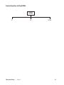
Soft Key:
RESOLUT
Setting the Resolution of the Displayed Weight
The high resolution Setra scale comes direct from the factory set at a readability that approximates the
linearity characteristics of the scale. That is to say, after calibration, the displayed weight for any object
placed into the center of the pan should not be off by more than the displayed increment from its true
value. However, the scale is capable of detecting much smaller weight changes than those displayed as
exemplified when counting very small pieces. The RESOLUT key can be used to increase displayed weighing resolution. Likewise, if the scale is not stable due to environmental factors such as draft or vibration, the
resolution can be decreased to prevent display instability.
To access the RESOLUTION settings in the Bases Setup menu, follow the menu tree or press the keys in the
order listed below:
tare
menu
remote
MORE
abc
SETUPS
BASES
SETUP
RESOLUT
reset
Press the RESOLUT soft key.
To program displayed increments, press the USER soft key. Using the numeric keypad, type in the last digit
of resolution in grams followed by the ENTER soft key.
NOTE: Only resolutions up to a maximum of the sampling resolution , typically of 1 part in 1,000,000 will
be accepted by the scale. All displayed resolutions in grams or any other unit of measure are rounded to
the closest 1, 2, or 5 digit increment. Programmed resolutions that are greater than the factory default
readability will be displayed with the last digit in reverse video as a notice to the user that the resolution is
greater than the linearity characterisitics of the scale.
To return to the scale’s default resolution which closely matches the scale’s linearity, press the DEFAULT
soft key.
Bases Setup
•
Super II
61
Bases Setup Menu: Soft Key INFO
1. BASE 1
2. BASE 2
3. BASE 3
4. BASE 4
5. BASE 5
6. BASE 6
7. BASE 7
8. BASE 8
INFO
Bases Setup
•
Super II
62
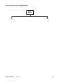
Soft Key:
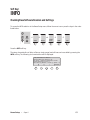
INFO
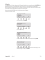
Checking Base Software Revision and Settings
To access the INFO selection in the Bases Setup menu, follow the menu tree or press the keys in the order
listed below.
tare
menu
remote
MORE
abc
SETUPS
BASES
SETUP
MORE
INFO
reset
Press the INFO soft key.
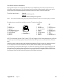
The setup characterisitics of either a Setra or strain gauge load cell base can be recalled by pressing the
INFO soft key. The following six characteristics will be displayed:
Base parameters for Base 1:
Software Revision Version 1.XX
Full Scale = 25000 g Sample Res. = 0.025
Display Resolution = 0.3 g
Zero Tracking Window = 0.500 g Speed = 3
GO BACK
Bases Setup
•
Super II
63
Bases Menu: Soft Key NAME
1. BASE 1
2. BASE 2
3. BASE 3
4. BASE 4
5. BASE 5
6. BASE 6
7. BASE 7
8. BASE 8
NAME
ENTER
Bases Setup
GO BACK
•
Super II
64
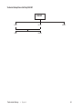
Soft Key:
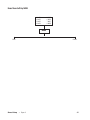
NAME
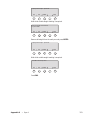
Changing the Name of a Base
To access the NAME selection in the Bases Setup menu, follow the menu tree or press the keys in the
order listed below.
tare
menu
remote
MORE
abc
SETUPS
BASES
SETUP
MORE
NAME
reset
Press the NAME soft key.
The identification name of a base can be changed to help clarify its function. Examples of this are LOCAL
and REMOTE for a dual scale system or SAMPLE, BULK, and PALLET for a three scale system.The only limitation when naming a base address is the six character description field.
Enter the Base Name (6 char max)
ENTER
GO BACK
Using the alphanumeric keypad (abc key), type in the new name followed by the ENTER soft key.
Bases Setup
•
Super II
65
Bases Menu: Soft Key ADDRESS
1. BASE 1
2. BASE 2
3. BASE 3
4. BASE 4
5. BASE 5
6. BASE 6
7. BASE 7
8. BASE 8
ADDRESS
GO BACK
Bases Setup
•
Super II
66
Soft Key:
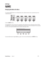
ADDRESS
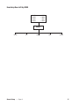
Changing the Address of a Single Base
The Super II controller is capable of communicating with up to eight separate bases. Each base on the
scale network must have a unique address from 1 to 8. As a default, all bases come from the factory set to
address 1. Additionally, the Remote Scale Option circuit boards for strain guage load cell remote bases
come from the factory set to address 2. To access additional Setra or strain gauge load cell bases or to
rename the current Setra or strain gauge load cell base, please follow the procedure below.
To access the ADDRESS changes in the Bases Setup menu, follow the menu tree or press the keys in the
order listed below.
tare
menu
remote
MORE
abc
SETUPS
BASES
SETUP
MORE
ADDRESS
reset
Press the ADDRESS soft key.
To add any additional bases beyond the standard Base 1 and Base 2 selections, or to reassign the address
of existing bases, follow the procedure below:
1.
Attach the Setra base to be reassigned directly to the controller.
2.
Apply power to the base.
3.
After scale countdown, the base will appear as Base 1 (or another number if it has already been reassigned).
4.
Access the Bases Setup menu by following the above procedure.
5.
Press the ADDRESS soft key.
6.
A menu will appear showing all eight possible base selections and the names associated with each base number.
Select the base to reassign:
1. Base 1
5. Base 5
2. Base 2
6. Base 6
3. Base 3
7. Base 7
4. Base 4
8. Base 8
GO BACK
Bases Setup
•
Super II
67
7.
Using the numeric keypad, select the base address to reassign.
8.
Using the numeric keypad, select the new address for the base.
9.
Unplug the base with the new address changes and plug it into the base which will be connected to the controller (Base 1).
NOTE: Once a network is setup with not more than one base per address, you can switch base addresses
without powering down the system.
Bases Setup
•
Super II
68
Bases Menu: Soft Key BASERST
1. BASE 1
2. BASE 2
3. BASE 3
4. BASE 4
5. BASE 5
6. BASE 6
7. BASE 7
8. BASE 8
BASERST
Bases Setup
•
Super II
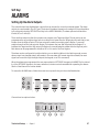
69
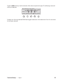
Soft Key:
BASERST
Resetting the Base
There may be times that the controller and the base network are out of sync. One example of this is the
addition of a base without the powering down of the controller. Base reset will cause the controller to
poll all addresses and search for bases.
To access the BASE RESET selection in the Bases Setup menu, follow the menu tree or press the keys in
the order listed below:
tare
menu
remote
MORE
abc
SETUPS
BASES
SETUP
MORE
BASERST
reset
Press the BASERST soft key to start the polling process.
Bases Setup
•
Super II
70
Technical Setup
Technical Setup
•
Super II
71
Technical Setup Menu: Soft Key GREETNG
GREETING
LINE 1
LINE 2
LINE 3
LINE 4
GO BACK
Type in information for each line up to 23 characters
Technical Setup
•
Super II
72
Soft Key:
GREETNG
Setting the Power-Up Greeting
When power is first applied to the scale, a greeting message is displayed showing the time and date along
with Setra’s address and telephone number. This occurs during the 30 second countdown procedure
while the scale performs a self-test. The greeting can be changed to a custom message. We recommend
either a dealer’s name and telephone number for service or the end user’s name and address to denote
property ownership.
To access the power-up greeting message, either follow the menu tree or press the keys in the order
listed below:
tare
menu
remote
MORE
abc
SETUPS
TECH
SETUP
GREETNG
reset
There are four lines of 23 characters available to set the desired greeting message.
Type Greeting and select line to enter:
LINE 1
LINE 2
LINE 3
LINE 4 GO BACK
Using the alphanumeric keypad (abc key) or PC keyboard, type in the desired message for each line (up to
23 characters) and press the LINE # key to specify where the text should appear.
Technical Setup
•
Super II
73
Technical Setup Menu: Soft Key BACKLIT
BACKLIT
BAT LIM
Enter maximum backlight
brightness under battery
power
Technical Setup
•
DELAY
Enter backlight shut-off
delay after last input
Super II
ON INPT
Select whether backlight
turns on with input on
BI port or digital inputs
GO BACK
74
Soft Key:
BACKLIT*
Backlighting of the Display
Adjustment of the backlight brightness can be done at any time from the front panel keys. Pressing and
holding the abc key and then pressing the left arrow key will decrease the brightness of the display.
Pressing and holding the abc key and then pressing the right arrow key will increase the brightness of the
display.
The controller can detect whether the scale is running off a (12 volt) battery or a (16 volt) AC adapter. The
scale can be set up to reduce the backlight brightness when running on batteries to save battery life. In
addition, the backlight will shut off when powered by batteries if the scale is not in use. Both of these
battery saving features are configurable.
To access backlighting battery power saving features, either follow the menu tree or press the keys in the
order listed below:
tare
menu
remote
MORE
abc
TECH
SETUP
SETUPS
BACKLIT
reset
After pressing the BACKLIT soft key in the Technical Setups menu , the following screen will appear:
Select backlight battery power
management value to set:
Battery brightness limit:
6
Shut-off delay time:
1.0 min.
On with B1 port or Dig. input: NO
BAT LIM
DELAY
ON INPT
GO BACK
If the BAT LIM soft key is pressed, the following display appears:
Enter maximum backlight brightness
under battery power (0 - 10):
Battery brightness limit:
ENTER
6
GO BACK
Brightness can be set to a whole number value between 0 (backlight off under battery power) to 10 (full
backlight brightness available under battery power). The factory default setting for the battery limit is 6.
* For scales with the backlight option.
Technical Setup
•
Super II
75
Press the DELAY key:
Select backlight battery power
management value to set:
Battery brightness limit:
6
Shut-off delay time:
1.0 min.
On with BI port or Dig. input: NO
BAT LIM
DELAY
ON INPT
GO BACK
The following screen appears:
Enter backlight shut-off delay after
last input (minutes):
Shut-off delay time:
ENTER
1.0 min.
DISABLE
GO BACK
Using the numeric keypad, press the desired power saving delay followed by the ENTER soft key.
When performing automated scale functions, such as computer communications through the BI port or
control by process equipment through the digital inputs, the back light will remain off. This behavior can
be changed using the ON INPT function.
Press the ON INPT soft key:
Select backlight battery power
management value to set:
Battery brightness limit:
6
Shut-off delay time:
1.0 min.
On with BI port or Dig. input: NO
BAT LIM
DELAY
ON INPT
GO BACK
The following screen appears:
Select whether backlight turns on
with input on BI port or Digital Inputs:
On with BI port or Dig. input: NO
YES
NO
GO BACK
The supervisor can select automatic reactivation of the backlight if input is received on the Bi-Directional
Serial Port or one of the Digital Input lines. The default is NO.
Technical Setup
•
Super II
76
Technical Setup Menu: Soft Key SETUP TRANSFR
SETUP
TRANSFER
CONTROLLER
SETUPS
Sends all controller
setups including macros
and print setups
ALL
SETUPS
Sends all controller setups
and base setups
DATBASE
RECORDS
Sends database records
BASIC
SETUPS
Sends controller setups
except prompting
macros and print setups
Technical Setup
TRANSAC
RECORDS
Sends transaction log records
MACRO
SETUPS
Sends each programmed
prompting macro
including step sequence
and prompts
•
RECORDS
Super II
MORE
GO BACK
GO BACK
PRINT
SETUPS
Sends each programmed
print key setup ; Eltron, DYMO
ScriptCoder setups saved in
their own formats
BASES
SETUPS
Sends the base setup
information except
current zero, current span
and linearity data.
GO BACK
77
Soft Key:
SETUP TRANSFR*
Transferring the Scale Setups to a Scale or Computer
The controller uses an interface language called the Setra Dialog Language (SDL). Using SDL, the setup
information can be transferred to another scale or to a computer file in order to back up the scale setups.
Through the SETUP TRANSFR menu, the entire scale setup, or a portion of the setups, can be sent out the BI
port.
To access the SETUP TRANSFR menu, follow the menu tree or press the keys in the order listed below:
tare
menu
remote
SETUPS
MORE
abc
TECH
SETUP
SETUP
TRANSFR
reset
The following screen and soft keys appear:
Select setups to upload:
CONTRLLR ALL RECORDS
SETUPS SETUPS
MORE
GO BACK
Pressing the MORE soft key will display the following additional choices:
Select the setups to transfer:
BASIC
SETUPS
MACRO PRINT
SETUPS SETUPS
BASES GO BACK
SETUPS
Press the RECORDS soft key:
Select setups to upload:
CONTRLLR ALL RECORDS
SETUPS SETUPS
* Available in Software Revisions 3.01 and higher.
Technical Setup • Super II
MORE
GO BACK
78
The following additional choices will be displayed:
Select the setups to transfer:
DATABASE
RECORDS
TRANSAC
RECORDS
GO BACK
Press one of the transfer options shown on the previous page to transfer some portion of the setups:
CNTRLLR SETUPS
Sends all the controller data including the prompting macros, print setups, and
controller setups (see below). Does not transfer the bases setup, transaction log
records or the database records.
ALL SETUPS
Sends all the above CNTRLLR setups as well as the base setups.
BASIC SETUPS
Sends the Controller setups described in this manual except the prompting macros
and the print setups.
MACRO SETUPS
Sends each prompting macro that has been programmed. Eltron, DYMO, and
ScriptCoder setups are saved in their own format.
BASE SETUPS
Sends the base setup information. The following items are not base setup information and cannot be read from the base: the current zero, the current span, and the
linearity data.
DATBASE RECORDS Sends the database records.
TRANSAC RECORDS Sends the transaction log records.
Technical Setup
•
Super II
79
Technical Setup Menu: Soft Key RESET
RESET
FACDEF
Restores all factory
settings and performance
characteristics
CLEAR
DB
NO
YES
YES
NO
Technical Setup
NO
CLEAR COUNT
Clears only the COUNT
register - the PART ID &
the rest of the record
information will remain
unaffected
CLEAR ALL
Clears all fields in the
database including all PART IDS
YES
CLEAR
PRINT
Clears all print
formats
•
Super II
CLEAR
MACRO
Clears all
programmed macros
YES
GO BACK
NO
GO BACK
80
Soft Key:
RESET
Resetting the Factory Defaults and Clearing the Database, Print Registers,
and Macros
Due to the programming flexibility of the scale, it may sometimes be desirable to go back to the factory
defaults as a launching point for new customization. To view the scale’s setups, send them to a computer
or printer by using the CONTROLLER SETUPS selection in the SETUP TRANSFR soft key section of this
manual. Separately, the scale’s Database, Print Registers, and Macros can each be cleared or reset for new
programming.
To access the RESET menu, follow the menu tree or press the keys in the order listed below:
tare
menu
remote
MORE
abc
SETUPS
TECH
SETUP
RESET
reset
There are four RESET choices available:
Select from the Reset Options below:
FACDEF
CLEAR
DB
CLEAR
PRINT
CLEAR
MACRO
GO BACK
FACDEF will restore all scale peformance parameters and RS232 setups to the factory default
settings.
Select from the Reset Options below:
FACDEF
CLEAR
DB
CLEAR
PRINT
CLEAR
MACRO
GO BACK
CLEAR DB will bring up the following options:
Technical Setup
•
Super II
81
Select from the database clearing options
listed below:
CLEAR
ALL
CLEAR
COUNT
GO BACK
CLEAR ALL will clear all database fields including the PART ID (ID0)
and leave the database completely empty. The transaction log is not
affected.
Select from the database clearing options
listed below:
CLEAR
ALL
CLEAR
COUNT
GO BACK
CLEAR COUNT will reset only the accumulated count register back to
zero for each record in the database to allow the same pieces to be
recounted. The transaction log is not affected.
Select Reset Option:
FACDEF
CLEAR
DB
CLEAR
PRINT
CLEAR
MACRO
GO BACK
CLEAR PRINT will clear all 10 print registers and leave them completely empty.
Technical Setup
•
Super II
82
CLEAR MACRO will clear all 10 prompting Macro registers and leave them completely
empty.
Select from the Reset Options below:
FACDEF
Technical Setup
•
Super II
CLEAR
DB
CLEAR
PRINT
CLEAR
MACRO
GO BACK
83
Technical Setup Menu: Soft Key AUTO SWITCH
AUTO
SWITCH
AUTOSWT
COUNT
Automatically switches
to selected counting base
after determining APW
Technical Setup
•
Super II
AUTOSWT
SAMPLE
Automatically switches
to selected sampling base
when SAMPLE key is pressed
GO BACK
84
Soft Key:
AUTO SWITCH
Selecting Special Remote Scale and Multiple Base Switching Options
This setup allows selection of special features for use in a two or more base scale system. There are two
setup options available that are listed below.
To access the AUTO SWITCH menu, either follow the menu tree or press the keys in the order listed below:
tare
menu
remote
MORE
abc
SETUPS
TECH
SETUP
MORE
AUTO
SWITCH
reset
Make a selection from the following two choices:
AUTOSWT COUNT:
When this feature is active, the controller will automatically switch to a
specified base after an APW is determined.
S e t t he fo l l o w i ng re mo t e s c a l e o p t io ns :
(toggle On/Off)
AUTOSWT AUTOSWT
COUNT
SAMPLE
AUTOSWT SAMPLE:
GO BACK
When this feature is active, the controller will automatically switch to a
specified base whenever the SAMPLE key is pressed.
S e t t he fo l l o w i ng re mo t e s c a l e o p t io ns :
(toggle On/Off)
AUTOSWT AUTOSWT
COUNT
SAMPLE
Note:
GO BACK
Please refer to the BASES SETUP menu if necessary to rename the bases to LOCAL and REMOTE or
SAMPLE and BULK or any other name, up to six characters.
Technical Setup
•
Super II
85
Technical Setup Menu: Soft Key ALARMS
ALARMS
ENABLE
DISABLE
ALARM 1
REGION1
Technical Setup
•
Super II
PROGRAM
GO BACK
ALARM 2
ALARM 3
LEVEL
LATCH
GO BACK
REGION2
REGION3
REGION4
GO BACK
GO BACK
86
Soft Key:
ALARMS
Setting Up the Alarm Outputs
The controller has three digital alarm outputs that can be used to control an external system. The alarm
output pins are located in the OUT port. The state of the alarm is based on the weight of the scale relative
to the set points (see the SETPOINTS soft key in the USER’S MANUAL). The alarm pins are held at either
Ø volts (LO) or 5 volts (HI).
There are three set points that the operator can program: Low, Target and High. The set points can be
programmed to any weight as long as the Low set point is lower than the Target set point and that, in turn,
is lower than the High set point. The three set points create four weight regions. Region 1 covers all
weights lower than the Low set point. Region 2 is between the Low and Target set points. Region 3 is
between the Target and the High set points. Region 4 covers all weights greater than the High set point.
Each alarm can be programmed to be either LO or HI in each of the four regions.
The alarm can be configured to be either latching or non-latching. When in the latching mode, once an
alarm output has changed state, it will remain in the new state until a reset signal is received (the reset
signal can be sent through the digital inputs, the keypad, or an SDL command).
When the alarms are programmed, the user menu selection SETPOINT changes to ALARMS. The functionality of the SETPOINT remains in the menu selection, but extra controls are added for operating the alarms.
See the “User Manual” for further details.
To access the ALARMS menu, follow the menu tree or press the keys in the order listed below:
tare
menu
remote
MORE
abc
SETUPS
TECH
SETUP
MORE
ALARMS
reset
Choose from the options below:
Alarm Outputs:
ALARM 1
ALARM 2
ALARM 3
ENABLE
Technical Setup
•
Super II
LOW
TARGET
HIGH
LO
HI
HI
LO
LO
HI
LO
LO
LO
DISABLE PROGRAM
LATCH
HI
HI
HI
GO BACK
87
When the alarms are disabled, all the outputs are set to their zero weight states. When the alarms are
enabled they follow the chart shown on the ALARM OUTPUTS screen where LO indicates that the alarm
pin will be 0 volts relative to ground and HI indicates 5 volts. Thus, on the display shown below, when the
weight is between the TARGET and HIGH set points the output of ALARM1 is HI, ALARM 2 is HI, and ALARM
3 is LO. Use the soft keys to enable and disable the alarms. Press the PROGRAM soft key to program the
chart.
When the program key is pressed,
Alarms Outputs:
LOW
TARGET
HIGH
LATCH
ALARM 1 LO
HI
HI
HI
ALARM 2 LO
LO
HI
HI
ALARM 3 LO
LO
LO
HI
ENABLE DISABLE PROGRAM
GO BACK
the following soft keys are shown:
Select Alarm to program:
LOW
TARGET
HIGH
LATCH
ALARM 1 LO
HI
HI
HI
ALARM 2 LO
LO
HI
HI
ALARM 3 LO
LO
LO
HI
ALARM1 ALARM2 ALARM3
GO BACK
Select ALARM1, ALARM2, or ALARM3 to program a particular alarm. When you select an alarm, the
following display appears:
Select program of LEVELs or toggle LATCH:
LOW
TARGET
HIGH
ALARM 1
LO
LO
LEVEL
HI
LATCH
LATCH
HI
GO BACK
If the LATCH soft key is pressed, a “lock” is displayed in the LATCH column, causing the alarm to be latching
(see above description). If no symbol is present in the LATCH column, the alarm is non-latching.
Select programming Alarm LEVEL or LATCH:
LOW
TARGET
HIGH
ALARM 2
LEVEL
Technical Setup
•
Super II
LO
LO
HI
LATCH
LATCH
HI
GO BACK
88
Press the LEVEL soft key to set the behavior of the alarm in a particular region. The following screen and
soft key is displayed:
Press a Region Key to invert a region:
LOW
TARGET
HIGH
LATCH
REGION1 REGION2 REGION3 REGION4
ALARM 2 LO
LO
HI
HI
REGION1
REGION2 REGION3 REGION4 GO BACK
Pressing one of the keys marked REGION will toggle the behavior of the alarm from LO to HI or vice-versa
for the region selected.
Technical Setup
•
Super II
89
Technical Setup Menu: Soft Key DIG INP
DIG INP
INPUT 1
INPUT 2
NONE
GO BACK
Technical Setup
•
Super II
GO BACK
90
Soft Key:
DIG INP
Setting the Digital Inputs
Digital Inputs allows an external system to signal the contoller to perform an action. There are two digital
input ports: Input 1 is located on pin 3 of the IN port and Input 2 is located on pin 5 of the IN port. The
input port is triggered when the voltage on the ports goes from Ø volts (off ) to 5 volts (on). When an input
is triggered, the controller performs a preselected action. The list of actions that can be selected include
zeroing, taring, printing, accumulating the weight or count, controlling the alarms, and controlling the
prompting macros.
To setup the DIGITAL INPUTS either follow the menu tree or press the softkeys in the order below:
tare
menu
remote
MORE
abc
SETUPS
TECH
SETUP
MORE
DIG INP
reset
The following menu is displayed and the soft keys change to:
Select Digital INPUT to be programmed:
INPUT 1: None
INPUT 2: None
INPUT 1
INPUT 2
GO BACK
The screen shows the current function that the INPUT 1 and INPUT 2 digital ports are programmed to
perform. Select the INPUT 1 or the INPUT 2 soft keys to program the input port function.
Pressing the INPUT 1 or INPUT 2 soft key will make the following menu and soft keys appear:
Select function of Digital INPUT 1:
1. Zero
5. Start Alarms
2. Tare
6. Stop/Reset Alarms
3. Print
7. Next Macro Step
4. Accumulate
8. Restart/Exit Macro
NONE
GO BACK
Using the numeric keypad, make your selection for the function of either INPUT 1 or INPUT 2.
Technical Setup
•
Super II
91
Technical Setup Menu: Soft Key SETUP SECURTY
SETUP
SECURTY
ENTER
Technical Setup
GO BACK
•
Super II
92
Soft Key:
SETUP SECURTY
Entering Technical Setup and Bases Setup Password Protection
This setup allows the setup of password protection for the Technical Setup and Bases Setup menus.
To access the SETUP SECURITY menu, either follow the menu tree or press the keys in the order listed
below:
tare
menu
remote
MORE
abc
SETUPS
TECH
SETUP
MORE
SETUP
SECURTY
reset
The following menu is displayed and the soft keys change to:
Enter the password (10 characters max.):
ENTER
GO BACK
A password up to 10 characters in length can be typed in using the alphanumeric keypad (abc key)
followed by the ENTER soft key.
ex: Type XYZ 123 followed by ENTER
If the ENTER soft key is pressed without entering any characters, password protection is canceled.
Note: Password is case sensitive.
Technical Setup
•
Super II
93
Technical Setup Menu: Soft Key HYSTERS
HYSTERS
ON
Technical Setup
OFF
•
Super II
GO BACK
94
Soft Key:
HYSTERS
Improving Display Stability
DISPLAY HYSTERESIS
Display hysteresis refers to the function which prevents the apparent “jumpiness” of a display that is
toggling between two weight readings. For example, if a weight is equal to 235.65 grams on a display
set to be read by .1 grams, the display may have trouble settling between 235.6 and 235.7. Display
hysteresis will prevent any changes to the display that are less than 1 displayed increment. Hysteresis
should only be turned on if the environment is unstable but the user requires the readability and
update rate of the current settings.
tare
menu
remote
MORE
abc
TECH
SETUP
SETUPS
MORE
MORE
HYSTERS
reset
1.
Access the HYSTERS setups menu by following the steps outlined above.
2.
Press ON to activate display hysteresis.
Hysteresis 'ON' prevents display changes
that are < 1 displayed increment
ON
OFF
GO BACK
NOTE: Hysteresis is OFF by default.
Technical Setup
•
Super II
95
Technical Setup Menu: Soft Key APW QTY
APW QTY
MODE 1
Technical Setup
MODE 2
•
Super II
MODE 3
SET NO.
PIECES
GO BACK
96
Soft Key:
APW QTY
Changing the APW Quantity Feature
The APW quantity feature is used to change the storage method of the APW. Normally, the APW, or Average Piece Weight, represents the average weight of a single piece. Using the APW Quantity feature, the
APW can be made to represent the weight of a number of pieces. Thus, if the need is to count dozens of
pieces, set the APW quantity to 12 and the APW displayed and printed will be the weight of a dozen pieces.
The APW mode sets the behavior of the scale when a new part is counted. The following APW quantity
modes are available:
Mode 1: APW Single Piece Mode
APWs are always entered and reported as the average piece weight of a single piece determined
by dividing the number of pieces in a sample into the total sample weight.
Mode 2: APW Quantity Mode
APWs are always entered and reported as the net weight of a pre-determined quantity of pieces.
This quantity is set using the SET NO./PIECES soft key. For example, when using an APW Quantity
of 1000, the scale will treat the entered APW value as the net weight of 1000 pieces and will use
this value to determine the total count from the weight on the pan.
Mode 3: APW Variable Quantity Mode
Similar to the APW Quantity Mode, this selection sets the scale’s default entry and reporting of the
APW to be based upon the net weight of a specific quantity, but allows the scale to receive APWs
through the RS232 port (from bar codes or from a PC) that are defined using the net weight of a
different number of pieces. The scale will temporarily use the net weight of a different number of
pieces received through the RS232 port until the RESET key is pressed. For example, in this mode a
scale set up for entry of APW 1000 will allow the use of APWs entered as the net weight of one
piece if the APW is scanned from a bar code label. By pressing RESET, the scale will revert back to
accepting keyboard entry of APW 1000.
To access the APW quantity setup, follow the menu tree or press the keys in the order listed below:
tare
menu
remote
MORE
abc
Technical Setup
SETUPS
TECH
SETUP
MORE
MORE
APW QTY
reset
•
Super II
97
The following screen and soft keys will be displayed:
Select APW Quantity mode or set pieces:
1) APW Single Piece Mode
2) APW Quantity Mode
3) APW Variable Quantity Mode
MODE 1 MODE 2
MODE 3 SET NO.
PIECES
GO BACK
Select the APW quantity mode desired using the MODE 1, MODE 2, or MODE 3 soft keys.
Press the SET NO. PIECES soft key to display the following screen and soft keys: Either select a predefined
APW quantity from the soft keys or enter a custom APW quantity using the numeric keypad and press
enter.
Select default pieces for APW quantity mode, or
enter pieces and press ENTER:
APW PIECES: 1000
ENTER
Technical Setup
•
Super II
APW 1
APW 12 APW 100 APW 1000
98
Appendix A
RS232 Serial Port Communications
The Super II comes equipped with three RS232 ports. They are labelled BI, for a “bi-directional” port for PC
or computer communications, OUT for an “output” port for a printer, and IN for an “input” port for a bar
code scanner. Users who have purchased Setra’s peripherals such as the Dymo SETRA 300 printer or the
Setra SmartWand can simply plug these devices into the appropriate port and start using them. The first
part of this appendix describes the RS232 command and communication protocol. The second part of the
appendix describes the characteristics of the ports.
Interfacing a Setra Super II Scale to a Computer
The bi-directional port interface not only allows the scale to transmit data to and from a computer, but
also enables a computer to control a scale. Since the baud rate and databits of this interface are selectable
(see PORTS soft key setup in this manual), virtually any computer or terminal with an RS232 port can be
connected to the scale. Setra Super II does not support software handshaking and supports hardware
handshaking only on the “bi-directional” port . This section describes the conventions and formats used to
communicate with the Super II.
Appendix A •
Super II
99
Sending Commands to the Scale
All functions which exist on the keyboard may also be accessed by a computer or a terminal by means of
the RS232 interface. Simply send the ASCII character which corresponds to a function. These characters are
shown in the following table:
FUNCTION
ASCII
FUNCTION
ASCII
APW
ID 7
COUNT
ID 1
exponential
ID9
GROSS/NET toggle
ID 6
integration filter
jump code
CLEAR
ID 3
ACCUMULATE
ID 4
SAMPLE
PRINT
APW quantity
ID 2
ID Ø
TARE
ID8
verify
wake-up
RESET
A
B
C
D
E
F
G
H
I
J
K
L
M
N
O
P
Q
R
S
T
U
V
W
X
ID5
ZERO
immediate print
ID start
ID finish
• or recall
REMOTE
0
1
2
3
4
5
6
7
8
9
TARGET SETPOINT
LOW SETPOINT
HIGH SETPOINT
x counter
y counter
add accumulate
subtract accumulate
Y
Z
#
/
$
•
>
0
1
2
3
4
5
6
7
8
9
^T
^L
^H
^X
^Y
^+
^-
Appendix A •
Super II
100
Never include a carriage return or line feed in any command sequence. The scale uses any command
character as a terminator for an input string.
For example, to enter a tare weight of 1000 (in the units currently being displayed), simply send “1000T”.
This will enter the number 1000 into the TARE register. To enter an average piece weight of 12.35, send
“12.35A”.
Sending Alphanumer ic ID #s to the Scale
Alphanumeric identification information (ID#s) may be entered into the scale through the RS232 interface.
Since Setra scales recognize upper-case ASCII characters as commands, it is necessary to begin alphanumeric entries with the “/” command or start ID character.
To enter an ID# from a computer or bar code scanner, the following string must be sent to the scale:
/ [ID string] $ (ID register character)
The ID START (or introducer) “/” instructs the scale to ignore subsequent characters as commands. The ID
FINISH (or terminator) “$” instructs the scale to interpret subsequent characters as commands. Everything
between ID START and ID FINISH will be stored as the ID string. The ID register character (see the table
below) instructs the scale to enter the string identifier into the ID# register.
The following table lists all ID register characters:
ID register #
ID register character
0
S
1
2
D
R
3
4
L
N
5
6
Y
H
7
8
B
U
9
F
ID register #1, 5, 7, 8, and 9 are not cleared when the reset key is pressed or when the unit is powered off.
These are referred to as non-volatile fields. ID register # 0, 2, 3, 4, and 6 are volatile and are cleared upon
reset and powering down.
The string identifier may consist of any printable ASCII character including upper case and lower case (AZ), numbers (0-9), punctuation (! . , : ; ? ’ ”) and symbols, ( ), [ ], { }, / \, +, = , *, %, &, #, < >, @ except the “$”. It
may be up to 23 characters in length. All other characters are ignored by the scale.
DO NOT SEND A CARRIAGE RETURN, <CR>, OR A LINE FEED, <LF>, WITHIN OR AFTER THE STRING IDENTIFIER.
Appendix A • Super II
101
Receiving Data From the Scale Using the Immediate Print Mode
The immediate print command “#” causes the scale to transmit whatever number or message appears in
the scale display. The value is formatted as shown below:
+/- 1 2 3 4 5 6 . c0 c1 c2 c3 CR LF
The first six digits represent the number field. A + or - sign always precedes a weight reading, and a decimal point is always transmitted, though their exact location depends on the number transmitted. Numbers
with less than six digits are preceded by spaces and the sign is always adjacent to the leading digit. The
specific location of the decimal point depends on the precision of the number transmitted.
“c0” is the speed mode character.
CHARACTER
F
MEANING
Scale is set to fastest speed
f
(space)
Scale is set to fast speed
Scale is set to normal speed
s
S
Scale is set to slow speed
Scale is set to slowest speed
“c1” is the “mode” character. It describes what the number being transmitted represents. The
following is a list of all possible mode characters:
CHARACTER
MEANING
(space)
Number field is a message or net weight
G
T
Number field represents GROSS weight
Number field represents TARE weight
A
M
Number field represents APW
Number field represents ACCUM contents
“c2” is the “units” character. It describes the units of the number being transmitted. The following is a list of
all possible characters sent in this digit:
CHARACTER
MEANING
G
Number is expressed in grams
O
P
Number is expressed in ounces
Number is expressed in pounds
Y
R
Number is expressed in troy ounces
Number is expressed in carats
D
K
Number is expressed in pennyweights
Number is expressed in kilograms
X
C
Number is expressed in user programmable unit
Number is expressed in pieces
Appendix A •
Super II
102
“c3” is the “stability” character. This character corresponds to the “OK” symbol on the display.
CHARACTER
(space)
MEANING
Reading is not stable
S
O
Reading is stable
Reading is over the base capacity
U
Reading is under the base capacity
The immediate print output is always terminated with a carriage return and line feed. To read data that
may be stored in a specific memory register, instruct the scale to display the data held in the particular
memory register by transmitting to the scale the memory recall command “.” followed by the memory
register of interest followed by the immediate print command “#”. For example, to read the contents of the
following registers, the following codes must be transmitted:
Register
Tare
Accumulator
Count
APW
Gross
Net
Transmit
.T#
.M#
.C#
.A#
.G#
.GG#
The following are some examples of immediate print output:
“– – – +1 2 . 3 - G P S” means that the GROSS weight is 12.3 lbs stable.
“– – – +1 0 0 0 0 - C -” means 10000 pcs, and the reading is not stable.
“– – – – + 8 4 . 6 - T O -” means that the TARE weight is 84.6 ounces.
Note: When the “#” immediate print command is entered via the IN port, output is via the OUTport; if the
input is via the BI port, output is also via the BI port.
Interval Print Mode
For continuous data output, use the PRINT INTRVL selection in the PRINT soft key section of the
Supervisor Menu to print the contents of the display every time a new reading or message is available. The
rate at which data is updated is variable and ranges from once every 0.2 seconds up to once every 24
hours. This mode is useful if the computer scale software interface runs as a background process.
The Jump Function
The Jump Function causes the scale to immediately operate in a given weight unit. Using this function
ensures that numbers, such as tare weight or average piece weight, entered through the RS232 interface
are interpreted in the correct units. For example, if the average piece weight was stored by a computer in
grams, it would be necessary to ensure that the scale was operating in grams prior to sending the APW to
the scale. This feature is only available through the RS232 interface.
Appendix A •
Super II
103
To use the Jump Function, send an nJ to the scale, where “J” is the Jump function command and “n” is the
unit code. The units code ranges from 0 to 7 as shown:
Units Code
0
1
2
3
4
5
6
7
Unit
User programmable unit (default GRAINS)
GRAMS
OZ (ounces)
LBS (pounds)
TROY (troy ounces)
DWT (pennyweights)
CARATS
KG
Do not send any number other than 0-7. For example, to enter an average piece weight of 0.23456 grams
from a computer, send “1J0.23456A”. The “1J” sets the scale for operation in grams. The “0.23456A” tells the
scale to enter that weight into the APW register. The Jump Function prevents misinterpretation of values
entered from a computer.
The Quantity Function
The Quantity Function operates very much like the “jump function” for the APW. By sending a numeric
value followed by the letter Q, the scale will then accept the APW that follows as the average piece weight
of the specified number of pieces represented by the numeric value preceding Q. For example, to send
1.2345 lbs as the APW of 1000 pieces, the scale needs to receive “3J1000Q1.2345A” (the 3J to specify the lb
units, 1000Q to specify 1000 quantity, and 1.23454A to specify the APW value).
An APW with a “Q” quantity can be entered with the scale in any APW Quantity mode but will only be
displayed in the entered quantity if the scale is set to the “APW Variable Quantity Mode”.
The Verify Function
When many scales or other peripherals are connected to a computer, it is sometimes useful for the computer to be able to check on the status of these devices. The verify function can be used to determine the
model number of a scale and determine that the scale is functioning correctly. To invoke the verify function, transmit an ASCII “V”. If the scale is functioning correctly, it will send out the following messages
followed by carriage return and line feed:
“Model 409
Base 1 capacity XXXXX”
Status After Power is Applied
All Setra scales have an internal nonvolatile memory for storing certain status information. This memory
does not erase when power is removed from the unit. All setup functions (such as print format, minimum
pieces, minimum accuracy, baud rate, and data base information) are stored in this memory. As a result, the
baud rate and print format will not need to be reset each time the scale is turned on.
During the first 30 seconds of operation, the scale will run through a self-diagnostic procedure. When the
unit is ready to be used, it will identify itself by transmitting a “wake-up” message. (This message can also
be invoked by sending a “W” to the scale.)
“Model 409
High Precision Weighing and Counting System
Software Rev X.XX
Base 1 Capacity XXXXX”
Appendix A • Super II
104
The RS232 Interface Hardware
Although Setra scales can communicate with almost any RS232 device, the built-in interface does not
include the complete protocol. Only the transmit and receive lines of the standard interface are used on
the OUT and IN ports respectively, and the transmit, receive, RTS and CTS lines on the BI port.
The default data format is:
1 start bit
8 data bits including parity
1 stop bit
10 bits per frame (framing errors ignored)
NOTE: The scale will transmit using the parity selected; however it does not check the parity it receives.
All serial ports use an eight pin modular connector. The pinout is as follows:
BI
1.
2.
3.
4.
5.
6.
7.
8.
OUT
ground
transmit out
receive in
RTS (Request To Send)
CTS (Clear To Send)
no connection
ground
ground
8
1
Jack
Modular Jack
Connector
Connector
(in back of scale)
(in back of controller)
1.
2.
3.
4.
5.
6.
7.
8.
ground
transmit out
no connection
Alarm 1
Alarm 2
no connection
ground
Alarm 3
IN
1.
2.
3.
4.
5.
6.
7.
8.
ground
no connection
receive in
Digital Input 1
Digital Input 2
+5V
ground
Digital Input 3
NOTE: The “handshake” signals “Clear To Send” (CTS) and “Request to Send” are implemented on the BI poer
only. This requires that the peripheral attached to the IN and OUT ports have a minimal buffer (15 characters).
In addition, some computers requiring hardware handshaking will need a connection between two pins
on the computer’s connector named DTR and DSR (Data Terminal Reading and Data Set Ready).
The maximum recommended cable length is 15 meters. The cable may be longer if it has less than 2,500
pF capacitance. The load impedance of the device connected should be between 3,000 and 7,000 ohms
with not more than 2,500 pF shunt capacitance. For more information, consult EIA Standard RS232: “Interface Between Data Terminal Equipment Employing Serial Data Interchange.”
Appendix A •
Super II
105
Appendix B
ScriptCoderTM Custom Label Printing
Your Super II scale can be programmed to print custom label designs on any serial printer, limited only by
the printer’s capabilities. This feature, called ScriptCoder™, allows a label design or RS232 output, to be
written using a series of codes which are stored in the scale’s memory. The set of codes, or script, is executed each time the specific label design is selected to print. The script can be written to create a customized output to a serial dot matrix printer, thermal bar code printer, or even a data collection device. The
Super II can store up to ten different scripts.
Ways to Create and Store a Script
A script contains preprogrammed text and data which is transmitted from the scale to the printer when
the appropriate print command is executed. There are four ways to create and enter a script; the best
method to use depends on the complexity of the label design and the peripherals available to the programmer.
The first method may be performed using only a Super II and involves entering codes directly through the
scale keypad. The second method involves the use of a QWERTY keyboard to enter a combination of
characters and codes. The third method involves scanning codes into the scale using a bar code menu
chart available in the ScriptCoder Label Design & Cable Kit (Setra P/N 404910). Finally, the fourth method
involves writing the script using the ScriptCoder PC program and downloading it to the scale via the BI
RS232 port (also available with the ScriptCoder kit).
Entering a Script via the Super II Keypad
All of the codes required for a script may be entered directly through the scale keypad. This method is
most suitable for simple label designs as shown in the following examples:
Part #: 123-456
APW: 2.56789 g
The following transmission sequence would be required from the scale:
- transmit the text “Part #:” and one space
- transmit the contents of the ID register
- transmit one carriage return and one line feed
- transmit the text “APW:” and one space
- transmit the contents of the APW register and one space
- transmit the unit designation letter
- transmit one carriage return and one line feed (for longer spacing or to feed between labels add
linefeeds or a formfeed to the end of this script to advance to the next label)
Before a script can be entered into the scale’s print memory, the scale must be setup to accept the programming codes. To perform this setup, follow the instructions under soft key PRINT in the Supervisor
Setups section of this manual. The following is the Script entry menu.
E nter each code or character now. PC
to download script. BARCODE to scan.
ENTER
Appendix B •
Super II
CODE
PC
BARCODE GO BACK
106
To produce the ASCII output below, enter the following script by using the numeric keypad followed by
the CODE soft key for each code. For alphanumeric characters, enter a single character and press the
ENTER key. To look up the numeric code associated with each character or scale function, refer to the
tables on page 116 through 120.
Part #: 123-456
APW: +2.56789 G
SCRIPT CODES -
Part #: (ID 0 is default register) <CR><LF>
80 CODE, 97 CODE, 114 CODE, 116 CODE, 32 CODE,
35 CODE, 58 CODE, 32 CODE, 128 CODE, 13 CODE, 10 CODE
SCRIPT CODES -
APW: (APW register) (Units ltr) <CR><LF>
65 CODE, 80 CODE, 87 CODE, 58 CODE, 32 CODE, 141 CODE,
32 CODE, 149 CODE, 13 CODE, 10 CODE [to add line feeds enter 10 CODE here; to add
a form feed enter 12 CODE here.]
DONE [to end script]
Each time the PRINT soft key is pressed (followed by the Print Register # if not the default), the scale will
output the above ASCII format and advance the printer to the next line or label.
Entering a Script using a QWERTY Keyboard
Simple scripts, such as the ASCII output above, can be more easily programmed by connecting a QWERTY
keyboard to the Super II controller. By using a combination of typed characters and numeric codes, the
entire script can be entered using the QWERTY keyboard.
Before a script can be typed in using a QWERTY keyboard, the scale must be setup to accept the formatting characters and programming codes. To perform this setup, follow the instructions under soft key
PRINT in the Supervisor Setups section of this manual.
The following is the Script entry menu.
E nter each code or character now. PC
to download script. BARCODE to scan.
ENTER
CODE
PC
BARCODE GO BACK
To produce the same ASCII output below, the script can be entered using the QWERTY keyboard. Type in
alphanumeric characters followed by the F1 function key or numeric formatting and scale registers codes
followed by the F2 function key.
Appendix B
•
Super II
107
Part #: 123-456
APW: 2.56789 g
SCRIPT - Part #: (ID 0 is default register) <CR><LF>
QWERTY KEYBOARD- P (F1), 2 (F1), r (F1), t (F1), : (F1), _ (F1),
128 (F2), 13 (F2), 10 (F2)
SCRIPT - APW: (APW register) (Units ltr) <CR><LF>
QWERTY KEYBOARD- A (F1), P (F1), W(F1), : (F1), _ (F1), 141 (F2), (F1),
149 (F2), 13 (F2), 10 (F2)[to add line feeds enter 10 (F2)
here; to add a form feed enter 12 (F2) here.]
(F5) [to end script]
Each time the PRINT soft key is pressed (followed by the Print Register # if not the default), the scale will
output the above ASCII format and advance the printer to the next line or label.
Entering a Script Using a PC
Please refer to the ScriptCoder Operator’s Manual in the ScriptCoder Label Design and Cable Kit.
(Setra P/N 404910)
Entering a Script Using a Bar Code
Please refer to the ScriptCoder Operator’s Manual in the ScriptCoder Label Design and Cable Kit.
(Setra P/N 404910)
Appendix B •
Super II
108
The following tables show the codes for the ASCII characters, ASCII control codes and Setra scale data
codes.
ASCII Characters
A
B
C
D
E
F
G
H
I
65
66
67
68
69
70
71
72
73
a
b
c
d
e
f
g
h
i
97
98
99
100
101
102
103
104
105
0
1
2
3
4
5
6
7
8
48
49
50
51
52
53
54
55
56
J
K
L
M
N
O
P
Q
R
S
T
U
V
W
X
Y
Z
74
75
76
77
78
79
80
81
82
83
84
85
86
87
88
89
90
j
k
l
m
n
o
p
q
r
s
t
u
v
w
x
y
z
106
107
108
109
110
111
112
113
114
115
116
117
118
119
120
121
122
9
space
57
32
Appendix B
•
Super II
109
Punctuation and Special Characters
!
“
#
33
34
35
$
%
&
‘
(
)
*
+
,
.
/
:
;
<
=
>
?
@
36
37
38
39
40
41
42
43
44
45
46
47
58
59
60
61
62
63
64
Appendix B •
[
\
]
^
—
‘
{
|
}
~
backspace
Super II
91
92
93
94
95
96
123
124
125
126
251
110
Setra Scale Data
ID 0
ID 1
ID 2
128
129
130
transmit ID field 0 “S” id
transmit ID field 1 “D” id
transmit ID field 2 “R” id
ID 3
ID 4
ID 5
ID 6
ID 7
ID 8
ID 9
Gross
Net
Tare
A.P.W.
A.P.W. exp.
Count
Acc Count
Acc Ct Ents
Acc Weight
Acc wt Ents
Units word
Units ltr.
Setra codes
131
132
133
134
135
136
137
138
139
140
141
142
143
144
145
146
147
148
149
150
Units jump code
X of “x or y seq.”
Y of “x or y seq.”
Time
Date
Pause (.1)
151
152
153
154
155
156
transmit ID field 3 “L” id
transmit ID field 4 “N” id
transmit ID field 5 “Y” id
transmit ID field 6 “H” id time
transmit ID field 7 “B” id
transmit ID field 8 “U“ id
transmit ID field 9 “F” id
transmit gross weight in external resolution
transmit net weight in external resolution
transmit tare weight in external resolution
transmit APW in internal resolution
transmit APW in exponential notation
transmit count
transmit count accumulator value
transmit count accumulator entries
transmit weight accumulator
transmit weight accumulator entries
transmit units label, e.g., “grams” or “pounds”
transmit units letter, e.g., “g” or “p”
ignored in scale, interpreted during setup to insert the appropriate scale control codes.
transmit units code number and J, e.g., “1J” or “3J”
transmits the X of the “X of Y” sequence.
transmits the Y of the “X of Y” sequence.
transmit the time hh:mm AM, from the Super II
transmit the date mm/dd/yy from the Super II
Pause for a specified time before continuing to transmit the
script.
(Argument code 1 to 99, e.g., 5 = .5 second pause, 25 = 2.5
second pause.)
Appendix B
•
Super II
111
Format Codes
Format Length
160
Set the length of the field to be printed.
(Argument code 1 to 99.)
Format Precision
161
Set the precision of the field to be printed. (Argument code 0 to
6.)
Format Sign
162
Transmit the “+” and “-” sign or only the “-” sign as appropriate.
(Argument code “+” or “-”, 43 or 45, respectively.)
Justification
163
Justify the field to the left or right. (Argument code “R” or “L”, 82
or 76, respectively.)
Fill Character
164
The fill is the character to be repeated in order to justify the
field and create the desired length. (Argument code: any
printable character, e.g., “*”,“0”, or space, 42, 48 or 32,
respectively.)
Absolute Value
165
Convert the formatted number to absolute value
All Capitals
166
Convert all letters in print field to capitals
Appendix B •
Super II
112
ASCII Control Characters
soh
stx
etx
eot
enq
ack
bel
bs
ht
lf
vt
ff
cr
so
si
dle
dcl
dc2
dc3
dc4
nak
syn
etb
can
em
sub
Appendix B
1
2
3
4
5
6
7
8
9
10
11
12
13
14
15
16
17
18
19
20
21
22
23
24
25
26
•
ctrl A
ctrl B
ctrl C
ctrl D
ctrl E
ctrl F
ctrl G
ctrl H
ctrl I
ctrl J
ctrl K
ctrl L
ctrl M
ctrl N
ctrl O
ctrl P
ctrl Q
ctrl R
ctrl S
ctrl T
ctrl U
ctrl V
ctrl W
ctrl W
ctrl Y
ctrl Z
Super II
esc
fs
gs
rs
us
del
27
28
29
30
31
127
113
Appendix C
Battery Option
Installation
Disassembly of the scale is required when installing the battery option kit.
1. Remove the pan and the pan support by removing the 3 screws marked “A” in Figure 1.
2. Remove the (2) Phillips head screws (marked “B” in Figure 2) and the rear panel.
3. Next remove the (4) Phillips head screws holding the rear power circuit board to the base casting.
4. Disconnect the rainbow cable and coiled cord. Remove the rear power circuit board.
5. Install the battery option circuit board and reconnect the rainbow cable and coiled cord. Make sure to loop the battery
connector out through the battery door opening.
6. Replace the (4) Phillips head screws to hold down the battery option circuit board.
7. Exchange the rear panel with the panel cut to accomodate the ON/OFF switch. Mount the new rear panel onto the scale
with the (2) Phillips head screws (marked “B” in Figure 2).
8. Remove the battery door, attach the battery connector to the battery, then insert the battery (cable end first) completely into
the scale.
9. Replace the battery door, the pan and pan support.
10. The scale is now powered for portable operation.
Figure 1
PAN
BUBBLE LEVEL
A
BATTERY DOOR
LOAD CELL
MODULE
REAR POWER
CIRCUIT BOARD
A
A
PAN SUPPORT
TRANSPORTATION
HOLDER FOR THE
AC ADAPTER
BASE
PAN SUPPORT
STOPS
Appendix C
•
Super II
114
Figure 2
B
BATTERY DOOR
B
ADJUSTABLE
FOOT
ON/OFF
SWITCH
DC POWER
CONNECTOR
REMOTE SCALE
CONNECTOR
ADDITIONAL
SETRA BASE
CONNECTOR
Battery Use for Portable Operation
A fully charged battery will allow the Setra Super II to operate for approximately 14 hours before recharging is needed. The battery will last two-thirds as long if the scale is equipped with either a backlight display,
a remote Scale Option or bar code scanner. The “low battery” indicator light on the front panel of the scale
will light up approximately 15 minutes before recharging is necessary. When battery power is too low for
proper scale operation, the circuit will automatically shut off the battery and the scale will cease operation.
Replacement batteries can be ordered from Setra Systems (part number 409740).
Battery Charging
When the “low battery” indicator light on the front panel of the scale turns on, use the following procedure
to recharge the battery:
1. Plug the AC adapter (Setra part number 404712) into an electrical outlet and plug the power cable into the scale. Do not
remove the battery. The scale will automatically recharge the battery from the electrical outlet.
2. The “low battery” indicator light will remain on during recharge until the battery reaches 40% of its rated capacity. This will
take about 2.5 hours with the scale power switch in the “ON” position, and two hours and ten minutes with the switch “OFF”. A
battery powering a scale alone will reach 95% of its rated capacity in 8 hours if the power switch is in the “ON” position
and in 7 hours if the switch is “OFF”. Note that the indicator light will not light up if the scale switch is “OFF”.
3. If the scale is equipped to power a Remote Scale Option or a bar code scanner from the scale’s battery, it is recommended that
battery recharging be done with the scale power switch in the “OFF” position.
4. The charging indicator light on the front panel of the scale will stay on until the battery reaches 95% of its rated capacity. Note
that the charging light will not be lit if the scale power switch is in the “OFF” position. Battery recharging time may vary
slightly depending upon the temperature in the scale operating environment.
Battery Storage
When storing your scale for an extended period of time, it is recommended that you disconnect
your battery completely from the recharging unit. Always recharge the battery before storage to
prevent damage to the battery.
Appendix C
•
Super II
115
Appendix D
Strain Gauge Load Cell Remote Scale Option
Installation
Disassembly of the scale is required when installing the optional strain gauge load cell base analog to
digital signal conversion PCB.
1. Remove the pan and the pan support by removing the 3 screws marked “A” in Figure 1.
2. Pop out the round connector plug from the hole marked “Remote Base” on the back cover.
3. Locate the two threaded holes in the left side of the bottom of the base casting (as viewed from the front of the base). Start a 6-32 x 3/8”
screw into each of the holes and turn them two revolutions each.
4. Refer to Figure 2. Pick up the circuit board and bracket assembly and orient it so that the flange with two slots is downward and the 6-pin
DIN connector faces the back. Lift the coil cord upward to the left and insert the bracket assembly into the base casting between the coil
cord and the load cell assembly, so that the straight section of the cord is against the back edge of the bracket assembly above the DIN
connector (circuit board face the load cell assembly).
5. Slide the circuit board back until the bottom of the bracket touches the back of the base casting and then slide the bracket to the left so
that the flange slots slide around on the 6-32 x 3/8” screws. The coil cord should lie beween the bracket and the left side of the base
casting.
6. Tighten down the 6-32 x 3/8” screws to hold the bracket in place.
7. Connect the Strain Gauge Remote Scale Option circuit board cable to the 10 pin header between the two RJ-45 jacks on the Rear Power
Circuit Board.
8. Reinstall the pan and pan support with the 3 screws.
PAN
9. The scale is now ready for Remote Base calibration and operation.
A A
PAN SUPPORT
A
LOAD CELL
MODULE
REMOTE CONNECTOR
PLUG
REMOTE OPTION A TO D
CIRCUIT BOARD
LOCATION
BASE
FRONT
Figure 1. Exploded view o f Super II bef ore Remote Scale Option Installation
Appendix D
•
Super II
116
.
.
COIL CABLE
REMOTE SCALE OPTION
CIRCUIT BOARD CABLE
RSO MOUNTING SCREWS
RSO MOUNTING BRACKET
.
RSO CIRCUIT BOARD
.
FRONT OF SCALE
Figure 2. Overview of Remote Scale Option Installation
Connector Wiring
If the cable connector of the remote scale base is physically compatible with the 6 pin circular DIN connector on the back of the Super II scale, proceed to Figures 4 and 5 to verify that it is electrically compatible.
Otherwise, damage may be caused to both the Super II scale and the remote scale base.
If the cable connector of the remote scale base is not compatible with the 6 pin circular DIN connector on
the back of the Super II scale, follow the procedures directly below.
NOTE: DISCONNECT THE SUPER II SCALE AND REMOTE SCALE BASE FROM ITS POWER SOURCE BEFORE
PERFORMING THE FOLLOWING PROCEDURES.
1. Remove the existing remote scale base connector.
2. Taking the connector supplied, separate the cord guard and metal housing by removing the screw.
3. Slide the metal housing onto the cable of the remote scale base. (See Figure 3.)
4. Strip 1/2" of the cable insulation.
NOTE: Do not nick, scrape or cut foil or braided shield when stripping cable insulation. Be equally
careful not to mar the wire insulation when stripping the shield or conductors when stripping the
wire insulation.
Appendix D
•
Super II
117
5. Fold back the shield and strip 1/10" from each wire.
Shield
Wires
Metal
Housing
Figure 3. Cable Preparation
6. Following the wiring diagram in Figure 4, solder each wire to the pin contact.
7. Make sure all of the wires do not make contact with each other, then crimp the plug extension to the shield of
the cable, solder to secure, if possible.
8. Slide the metal housing over the plug and secure with the screw using a small screwdriver.
#4
- signal
Figure 4. View from solder end o f
shielded DIN plug connector
- signal
#5
+ sens
.
+ sens
- sens
#3
+ signal
#6
- sens
+ signal
- exc
+ exc
#2
- exc
#1
+ exc
Figure 5. 6 Pin circular DIN Connector on back o f Super II Scale
Appendix D
•
Super II
118
Calibration
The calibration of the Strain Gauge Load Cell Remote Scale Option is accessed through the BASECOM soft
key of the CALIB menu in the Bases Setups (see CALIB section in this manual). Before entering the
BASECOM selections, make sure that the controller is monitoring the Strain Gauge Load Cell Remote Base
by entering the proper Base address number with the remote key.
Upon entering the BASECOM mode, the following screen will appear:
(User input is shown in bold)
Select a function and press ENTER
1) Test modes
2) Calibration
3) Set sampling res.
4) Escape
NO
YES
ENTER
END
Press 2 and then press ENTER.
Present calibration data will be lost.
Continue calibration?
(enter YES or NO)
NO
YES
ENTER
END
Press the Yes soft key.
Select calibration units and press ENTER
1) Grams
2) Kilograms
3) Pounds
4) Ounces
NO
YES
ENTER
END
Press the number for the desired units (1-4) followed by ENTER.
Enter full scale capacity of the
remote base and press ENTER
NO
YES
ENTER
END
Using the numeric keys enter the value of the full scale capacity in the
selected weight unit and press ENTER.
Appendix D
•
Super II
119
Enter the display resolution and
press ENTER
NO
YES
ENTER
END
Enter the desired display resolution increment in the selected weight
unit and press ENTER.
Note: The display resolution cannot be greater than 1/50,000 of full
scale capacity.
Enter calibration weight
and press ENTER
(for best results, calibration weight
should be 25% or more of capacity)
.
NO
YES
ENTER
END
Enter the value of the calibration weight and press ENTER.
Remove all weight from scale base
and press ENTER
NO
YES
ENTER
END
Remove all weight from the scale pan and press ENTER.
Acquiring stable weight - please wait
NO
YES
ENTER
END
Wait while a stable reading is acquired.
Place (calibration weight) (units) on scale base
and press ENTER
NO
YES
ENTER
END
Place the previously entered calibration weight on the scale pan and
press ENTER.
Appendix D
•
Super II
120
Acquiring stable weight - please wait
NO
YES
ENTER
END
Wait while a stable weight reading is acquired.
Remove all weight from scale base
and press ENTER
NO
YES
ENTER
END
Remove all weight from the scale pan and press ENTER.
Acquiring stable weight - please wait
NO
YES
ENTER
END
Wait while a stable weight reading is acquired.
Enter END to exit factory menu
NO
YES
ENTER
END
Press END.
Appendix D
•
Super II
121
Appendix E
SPECIFICATIONS
CAPACITY
READABILITY
REPRODUCIBILITY
NON-LINEARITY
27 lb
0.0005 lb
± 0.0005 lb
± 0.00005
35 lb
0.0005 lb
± 0.0005 lb
± 0.00005
55 lb
0.001 lb
± 0.001 lb
± 0.001 lb
65 lb
0.001 lb
± 0.001 lb
± 0.001 lb
110 lb
0.002 lb
± 0.002 lb
± 0.002 lb
CAPACITY
READABILITY
12,000 g
0.2 g
± 0.2 g
± 0.2 g
16,000 g
0.2 g
± 0.2 g
± 0.2 g
25,000 g
0.5 g
± 0.5 g
± 0.5 g
30,000 g
0.5 g
± 0.5 g
± 0.5 g
50,000 g
1.0 g
± 1.0 g
± 1.0 g
Appendix E •
Super II
REPRODUCIBILITY
NON-LINEARITY
122
CONTROLLER
Display type:
Graphics LCD
Display units:
Grams, Ounces (avoir du poids), Pounds, Pennyweights (dwt), Troy ounces,
Carats, Kilograms, Grains, User-definable units
Display resolution:
Display update rate:
Selectable
Selectable from 5 settings.
Internal resolution:
Selectable to 1 part in 1,000,000
Counting accuracy:
Selectable from 90% to 99.99%
Counting capacity:
9,999,999 pieces
Data entry:
Printing:
Database:
Macro operation:
Multiple base connectivity:
Numeric keypad with alpha-register and changeable soft keys
QWERTY keyboard connectivity
10 programmable print registers
750 records for database and/or transaction log storage of up to 9
fields of information
10 programmable macros for step by step prompting operations
Up to 8 bases in any combination of Setra or strain gauge bases
Data communications:
3 RS232 ports:
1 IN port for bar code scanner*
1 OUT port for printer**
1 BI bidirectional port for computer device or PC
Selectable baud rates:
1200, 2400, 4800, 9600
Selectable parity:
8 NONE, 7 ODD, 7 EVEN
Dimensions:
101/2” L x 41/2 “ W x 21/2” H (with rear foot installed)
(27 cm L x 11 cm W x 6.5 cm H)
BASE
Construction:
Dimensions:
(25 - 50 kg)
(12 - 16 kg)
Cast aluminum housing
121/2 “ W x 143/4” D x 4” H (with feet retracted)
(31.5 cm x 37.5 cm x 10 cm)
11 1/2 “W x 9 1/4”D x 4 3/4”H (with feet retracted)
(29 cm x 24 cm x 10.5 cm)
*
Setra barcode scanner options include the Smart Wand (p/n 403674) and the Linear Imager Gun for Scale (p/n 403678).
**
Setra printer options include the Dyno SETRA 300(p/n 401160).
Appendix E •
Super II
123
PAN
Construction:
Stainless steel
Dimensions:
(25 - 50 kg)
13 “ W x 15 1/4” D x 1 1/2” H
(33 cm x 24 cm x 4 cm)
(12 - 16 kg)
11 1/2 “ W x 14” D x 1 1/2” H
(29 cm x 24 cm x 4 cm)
DIMENSIONS
Overall:
(25 - 50 kg)
(12 - 16 kg)
13 “ W x 15 1/4 ” D x 4 1/2” H
(33 cm x 38.5 cm x 11.5 cm)
11 1/2 “W x 9 1/2 ”D x 4 3/4”H (with feet retracted)
(29 cm x 24 cm x 12 cm)
With controller attached:
(25 - 50 kg)
13 “ W x 19” D x 4 1/2” H
(33 cm x 48 cm x 11.5 cm)
(12 - 16 kg)
11 1/2 “W x 9 1/2 ”D x 4 3/4”H (with feet retracted)
(29 cm x 35 cm x 12 cm)
GENERAL
Operating temperature:
Power requirements:
Shipping weight:
(25 - 50 kg)
(12 - 16 kg)
Appendix E •
Super II
40 o to 110 o F (5 o to 43 oC)
10 - 90% RH non-condensing
12 - 16V DC @ 800 mA
US AC adapter: 16 V DC @ 550m A
Optional 12 VDC@ 500m A EC fpr 230 VAC, 50 Hz
Base: 33 lbs (15 kg)
Controller: 3 lbs (1.5 kg)
Combination: 35.5 lbs (16 kg)
Base: 16.8 lbs (7.5 kg)
Controller: 3 lbs (1.5 kg)
Combination: 19.8 lbs (9 kg)
124
Appendix F
Glossary of Terms
Accuracy
The degree of conformity of a measured value to the true value.
APW
Enhancement
A scale feature whereby the scale uses a preliminary average piece weight to
count parts, allowing the operator to increase the sample size without hand
counting. When the targeted sample size is obtained the average piece
weight is recalculated for final counting with greater precision.
Average
Piece Weight
The value calculated by dividing the quantity of parts in the sample into the
weight of the sample. This value is stored in the scale and divided into the
weight of the bulk load to provide a total count.
Base
The portion of the scale that receives the load to be weighed.
Baud Rate
The rate at which a scale transmits or receives information to or from a
computer or peripheral device.
Controller
The portion of the scale that includes the keypad, display, battery status LED’s
and ports for communicating with the scale base and peripheral devices.
Counting
Capacity
The largest number of pieces that can be shown on the controller’s display.
Counting
Resolution
(Also, “internal counting resolution” or “internal resolution”)The ratio of a
scale’s capacity to the weight of the lightest part placed on a scale’s weighing
element which can be counted in increments of one part.
Displayed
Resolution
The ratio of the weighing capacity of the scale to its readablility.
Display
Hysteresis
The tendency of a scale, with a fluctuating reading, to stabilize on the most
consistent value.
Dual
Scale System
A counting system usually involving a low capacity local base for sampling
and a high capacity remote base for weighing the bulk load.
Gross Weight
The weight of the contents (net weight) combined with the weight of its
container (tare weight).
ID
Abbreviation for “identifier”. An identifier can be a part number, lot number, or
item description and can be entered into one of several available fields in the data
base.
Kitting
The counting procedure that involves repeatedly counting out small quantities of a
given part to be packaged with other parts that will be used together in an assembly.
Appendix F
•
Super II
125
Macro
A series of preprogrammed scale functions that are initiated by a keypress, and by
means of display prompts, will guide an operator through a weighing or counting
operation.
Menu
Refers to the numerous choices presented in the display as labels for the soft key. Also,
the hard key that provides access to additional scale features.
Minimum
Accuracy
The setting expressed as a percentage that determines the smallest sample weight
required to count uniform parts with an error that is no larger than that selected.
Net Weight
The weight of the contents of a container, without the weight of the container.
Parity
A bit used to check the validity of the data word.
Precision
The degree to which a weight measurement deviates from the average of repeated
measurements, usually expressed as one standard deviation (or one sigma).
QWERTY
Term used to describe the typical keyboard found on a personal computer or type
writer. QWERTY refers to the top row of letters on the keyboard.
Readability
The smallest weight increment shown on a display.
Register
A memory location within the scale where specific data is stored.
Remote Scale
One or more additional Setra or strain gauge load cell bases, that are accessed by
means of the “remote” key on the controller keypad.
Reproducibility
See “PRECISION”
Resolution
The smallest change in mechanical input which produces a detectable change in the
output signal.
Set Points
Target weight or count values that can be entered into the scale for filling or check
weighing applications. Set Points can be used to indicate when a weight or count is
within a specified range.
Span
The calibration point which when combined with zero determines the slope of the line
that tracks the measured weight values as a function of applied load.
Tare
The weight of an empty container. Also, the process of storing the weight of an empty
container and zeroing the scale’s display.
Transaction Log
A location in the scale’s database where the results from each counting or weighing
operation are stored in chronological order.
Unit of Measure
One of several available measures of weight such as grams, kilograms, pounds or
ounces.
Zero Tracking
Automatic subtraction of small changes in weight readings due to temperature or
other enviromental factors to maintain a displayed reading at zero over an extended
period of time.
Appendix F
•
Super II
126
Appendix G
Setra Systems, Inc.
Limited Two-Year Scale Warranty
Setra Systems, Inc. warrants the scales it manufactures to be free from defects in material and workmanship. Upon return, transportation charges prepaid, to Setra’s factory within two (2) years of the date of
purchase, Setra will repair or replace, at its option, any scale which it determines to contain defective
material or workmanship and will return said scale to purchaser, transportation prepaid, at any point in the
United States. Setra shall not be obligated, however, to repair or replace scales which have been repaired
by unauthorized parties, abused, improperly installed, altered, or otherwise misused or damaged, even if by
accident, in any way. Setra will not be responsible for any dismantling, reassembly or reinstallation charge.
Nothing in this warranty shall be construed as a warranty for merchantability or fitness for any specific use
or purpose, and this warranty is in lieu of all other warranties, express or implied. Setra shall not be held
liable under the terms of this warranty for any special, indirect, incidental or consequential damages
claimed in connection with the scale’s performance or availability.
Setra Systems, Inc.
Weighing Systems Division
159 Swanson Road
Boxborough, MA 01719
(978) 263-1400
1 (800) 257-3872
Fax (978) 635-9551
.
Appendix G
•
Super II
127
Appendix H
WARNINGS
WARNING: IF THIS EQUIPMENT IS USED IN A MANNER NOT SPECIFIED BY THE
MANUFACTURER, THE PROTECTION PROVIDED BY THE EQUIPMENT MAY BE IMPAIRED
!
USE SETRA REPLACEMENT BATTERY ONLY, PN 409740, LEAD-CALCIUM TYPE BATTERY.
!
POSSIBLE PINCH POINT. DO NOT PLACE FINGERS BETWEEN LOAD PLATE AND CHASSIS.
WARNING: DO NOT IMMERSE SCALE
WARNING: INDOOR USE ONLY
CLEANING : To clean the scale, use a damp cloth on the exterior of the scale. Do not
clean with solvents.
Appendix H
•
Super II
128
FCC Warning
This equipment has been tested and found to comply with the limits for a Class A digital
device pursuant to Part 15 of FCC Rules. These limits are designed to provide reasonable
protection against harmful interference when this equipment is operated in a commercial
environment. This equipment generates, uses, and can radiate radio frequency energy and,
if not installed and used in accordance with the instruction manual, may cause harmful
interference to radio communications. Operation of this equipment in a residential area
may cause harmful interference, in which case, the user must correct the interference.
Canadian Department of Communications
This digital apparatus does not exceed the Class A limits for radio noise emissions from a
digital apparatus set out in the Radio Interference Regulations of the Canadian Department of Communications.
Le présent appareil numerique n’emét pas de bruits radioeléctriques depassant les limités
applicables aux appareils numeriques de la classe a préscrites dans le reglément sur le
brouillage Radioeléctrique edicté par le Ministre des Communications du Canada.
EC Declaration of Conformity
The product manufacturer,
Setra Systems, Inc.
This Declaration of Conformity
is in accord
with European Standard EN 45014
General Criteria for Supplier’s
Declaration of Conformity.
The basis for the criteria can be found in
international documentation, particularly in
ISO/IEC, Guide 22, 1982, Information on
Manufacturer’s Declaration of Conformity
concerning standards and other technical
specifications.
This declaration is an
EC Type Declaration of Conformity
as referenced in article 10.1 of
EC directive 89/336/EEC
The EMC-directive
and as in Appendix III.B of
EC directive 73/23/EEC
The Low Voltage Directive
159 Swanson Road
Boxborough, Massachusetts 01719
U.S.A.
declares under its sole responsibility that the product,
Super IITM Electronic Weighing and Counting Scale
to which the declaration relates is in conformity with the following European
harmonized and published standards as of the date of this declaration;
EN61326 (CISPR 11, Group 1, Class B) Electronic Equipment for Measurement, Control,
and Laboratory Use EMC Requirements
EN55022/CISPR 16:1992 Radiated Emissions,
30 – 230 MHz, 30dBmV/m @ 10m
230-1000MHz, 37dBmV/m @ 10m
EN55022/CISPR 16:1992 Conducted Emissions,
150kHz - 0.5MHz 66-56dB(mV) QP, 56-46dB(mV) AV
0.5MHz – 5MHz 60dB(mV) QP, 50dB(mV) AV
5MHz – 30MHz 56dB(mV) QP, 46dB(mV) AV
EN61000-3-2:1995 Harmonized Emissions
EN61000-3-3:1995 Flicker Emissions
EN61000-4-2:1995 Electrostatic Discharge 4kV contact and 8kV
Air Discharge Performance Criteria B
EN61000-4-3:1996 Electromagnetic Field Immunity, 3V, 80%
AM Modulated at 1kHz, Performance Criteria A
EN61000-4-5:1995 Surges on AC Power Mains, 0.5kV Differential,
1kV Common Mode, Performance Criteria B
EN61000-4-6:1996 Conducted RF Current Injection on AC
Power Mains, 3Vrms, Performance Criteria A
EN61000-4-11:1994 Voltage Dips and Interuptions on AC Power
Mains, 0.5 Cycle Each Polarity, 100%
EN61010-1:1993 Safety Requirements for Electrical Equipment
for Measurement, Control, and Laboratory Use
These conclusions are based on test report:
EN61326: 1998 TEST Report for Setra Systems on the Super II Scale with Backlighting
Model(s)409
and
EN61326 (CISPR 11, Group 1, Class B) Emissions Testing Performed on the Setra
Systems Weighing Scale, Model 409, Super II with Backlighting Option
Technical Information File is maintained at:
Setra Systems, Inc.
159 Swanson Road
Boxborough, Massachusetts 01719
U.S.A.
Tel:
(978) 263-1400
Fax:
(978) 635-9551
Year of CE Marking:
2001
I do hereby declare that the product specified above conforms to the listed
directives and standards.
James J. Vecchio
Vice President
Weighing Systems Division
Setra Systems, Inc.
Index
6 Pin circular DIN Connector 118
A
abc key 40, 73
AC adapter 114, 115
ACCUM 45
ACCUMULATE 100
Accuracy 6, 125, 126
Programmable 6
accuracy setting 21, 23
ACCURACY SETUP 6, 21, 23
add accumulate 100
ADD CT 45
ADDRESS 8, 67
ALARM 88
ALARMS 8, 86
ALL SETUPS 79
Alphanumeric ID 101
APW 45, 100, 125
APW Enhancement 125
APW QTY 8, 96
APW quantity 97, 100
APW Quantity Mode 97
APW Single Piece Mode 97
APW Variable Quantity Mode 97
ASCII 101
characters 109
control characters 113
control codes 109
AUTO SWITCH 8, 84, 85
AUTOMAT/STEP 44
AUTOSWT COUNT 85
AUTOSWT SAMPLE 85
Average Piece Weight 107, 125
B
BACKLIT 8, 74
Bar Code 108
BARCODE/SC ENG 13
BASE 45, 46, 114, 116, 123, 125
base
multiple, switching options 85
BASE SETUPS 79
BASECOM 119
BASERST 8, 70
BASES 85
BASIC SETUPS 79
Battery
Charging 115
Option 114
Storage 115
Baud Rate 5, 23, 99, 125
BEEPER CONTROL 8, 49
BI port 23, 99
Index • Super II
bi-directional 99
BULK 85
C
cable 117
CALIB 8, 53
Calibration 53, 119
Canadian Department of
Communications 129
CAPACITY 122
CE Declaration of Conformity 130
Changing the Address of a Single Base
67
CHARACTER 102
CLEAR 45, 100
CLEAR ALL 82
CLEAR COUNT 82
CLEAR DB 81
CLEAR MACRO 83
CLEAR PRINT 82
Clearing 81
CNTRLLR SETUPS 79
CODE 107
code 106, 109
format 112
connector
circular DIN 117
remote scale base 117
Connector Wiring 117
Construction 124
Controller 125
CONVERT 29
CoStar 11
COUNT 21, 100
Counting
accuracy 123
capacity 123, 125
resolution 125
CUSTOM/PROMPT 44
customization 5
Customizing 42
D
data collection device 106
Data communications 123
Data entry 123
Database 31, 123
Internal 5
database
format 32
records 31
transactions 31
DATABASE SECURTY 33
DATABASE SETUP 30
databit/parity 23
databits 99
DATBASE 32
DATBASE RECORDS 79
DATBASE SETUP 6, 8, 31
DATE/FORMAT 25
DEFAULT 61
default 5
Defaults 81
DESC 39
DIG INP 8, 91
Digital Inputs 91
Dimensions 123, 124
Display 125
Display Hysteresis 95, 125
display
instability 61
noise 59
resolution 123, 125
type 123
units 123
update rate 95, 123
displayed weight 61
Dual Scale System 125
Dymo® SETRA 300 5, 11
DYMO®* Setra 300/COSTAR 13
E
Eltron 5, 11, 15
ENDCT 45
ENGLISH 13, 25
ENGLISH/MONTH 25
European format 25
EXIT 45
exponential 100
F
FACDEF 81
Factory Defaults 81
factory settings 5
FCC Warning 129
field identifiers 5
fields
ID 39
non-volatile 39
to print 15
volatile 39
Format Codes 112
G
Glossary 125
GRAINS 28
GRAMS 28
131
Graphics LCD 123
GREETING 8, 72, 73, 95, 97
Greeting Message 73
Gross Weight 125
GROSS/NET toggle 100
H
handshaking 99
hardware handshaking 23
HIGH 45
HIGH SETPOINT 100
HYSTERESIS 95
HYSTERS 8, 94
I
ID 45, 46, 100, 125
ID Ø 100
ID 1 100
ID 2 100
ID 3 100
ID 4 100
ID 5 100
ID 6 100
ID 8 100
ID 9 100
ID field 39
ID finish 100
ID NAME 8, 35, 39
ID NAME SETUP 8, 38
ID start 100
ID# register 101
immediate print 100
IN and OUT ports 23
IN MENU 19
INFO 8, 63
INPUT 91
integration filter 100
Internal Database 5
Interval Print Mode 103
J
jump code 100
Jump Function 103
K
Keyboard, QWERTY 107
Keypad 40, 106
alphanumeric 40
keypad entry script 106
Kitting 125
L
LABEL 13
Index • Super II
132
label 11
design 106
design, simple 107
Label Printing 106
LARGE/ENGLISH 13
LATCH 88
LEVEL 89, 114
LINEARITY 54
Calibration 54
Load Cell 114, 116
LOCAL 85
LOT 39
LOW 45
low battery 115
LOW SETPOINT 100
P
MACRO 42
Macro 126
Macro operation 123
MACRO SETUPS 8, 79
macro step
PRINT 46
Macros
prompting 6
customizing 42
programming 43
prompting 42
prompts 45
MACROSETUP 41
memory 106
Menu 126
MILITARY/D MTH Y 25
mode 102
Multiple base connectivity 123
Multiple Scale Systems 5
PAN 114, 116, 124
PAN SUPPORT 114, 116
PAPER 13
Parity 126
PART ID 31
Password Protection 48, 93
PC 108
Portable Operation 115
PORTS SETUP 6, 22
Power requirements 124
Precision 126
PRINT 6, 11, 12, 45, 46, 100, 106
DATBASE 12
FORMATS 12
INTERVL 12,17
SETUP 6, 11
TRANSFER 32
PRINT/KEY 12
PRINT format programming 12
printer, serial 106
thermal bar code 106
printers
CoStar 250 5, 11
Eltron 5, 11
ScriptCoder 5
Printing 5, 11, 123
Create-a-Label 11, 15
ScriptCoder 11
PROGRAM 88
PROGRAM MACRO 43
programming 5
Programming a Macro 43
Prompting 42
Prompting Macros 6
Punctuation 110
N
Q
Name 8, 29, 39
Net Weight 126
network of bases 5
NEXT 45
NON-LINEARITY 122
NON-VOLATILE 39
Quantity Function 104
QWERTY 107, 126
M
O
ON/OFF 29
Operating temperature 124
OPRTR 39
ORDER 39
output 106, 107
OZ 28
R
Readability 122, 126
RECL DB 45
Region 87
Register 126
REMOTE 85, 100
Remote Scale 85, 116, 126
remote scale base 117
Remote Scale Option Installation
116, 117
Reproducibility 122, 126
RESET 8, 45, 80, 81, 100
Resetting 81
RESOLUT 8, 61
Resolution 29, 61,126
counting 125
displayed 125
RESTART 45
REV 39
RS-232 23, 99, 105, 106
S
SAMPLE 6, 19, 85, 100
minimum size 19
size selection menu 19
SAMPLE SETUP 6, 18
Sample Size 6
SAVE DB 45
SAVE TL 45
scale data codes 109
SCREEN 8
script 106, 107
codes 109
entering 106
entering, keypad 107
keypad entry 109
writing 106
ScriptCoder 5, 11, 106
ScriptCoder Label Design & Cable Kit
106
SECURTY 8, 48, 50, 93
Selectable
baud rates 123
parity 123
Set Points 87, 126
SET PTS 45
SET/DATE 26
SET/TIME 26
SETRA 300 5
Setra Dialog Language (SDL) 78
Setra Scale Data 111
Setra Systems, Inc. 127
setup 106
SETUP SECURITY 8, 47, 92
SETUP TRANSFER 8, 77
shield 118
Shipping weight 124
SMALL/ENGLISH 13
Span 126
SPAN Calibration 53
Special Characters 110
SPECIFICATIONS 122
SPEED 57
speed 102
stability 103
STANDRD/PROMPT 44
Status After Power 104
Strain Gauge 116
SUB CT 45
Index • Super II
subtract accumulate 100
T
TARE 45, 100
Tare 126
TARGET 45
TARGET SETPOINT 100
TIME/DATE 6, 25
TIME/FORMAT 25, 26
TL RECORD 35
TRANSAC RECORDS 79
TRANSAC SETUP 8, 34
Transaction Log 5, 35, 126
transmission sequence 106
U
Units 6, 102
of measure 6
user definable 29
UNITS 45, 46
UNITS ENABLED 6, 27
UNITS ON 6, 28
Update Rate 57
UPDATE SPEED 8
USER 61
user definable unit 29
V
VENDOR 39
verify 100
Verify Function 104
VOLATILE 39
W
wake-up 100
WARNINGS 128
Warranty 127
Weighing Units 28
wire 118
X
x counter 100
X UNIT 45
Y
y counter 100
Y UNIT 45
Z
ZERO 45, 53, 100
ZERO TRACK 8, 59
Zero Tracking 59, 126
133