1
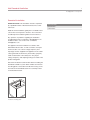
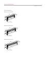
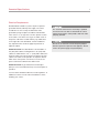
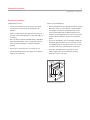
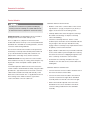
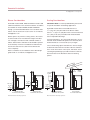
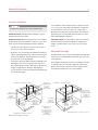
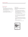
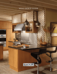
INSTALLATION GUIDE
Downdraft Ventilation
Contents
Important Note
Wolf Downdraft Ventilation . . . . . . . . . . . . . . . . . . . . . . 3
To ensure the safe and efficient use of Wolf equipment,
please take note of the following types of highlighted
information throughout this guide:
Installation Considerations . . . . . . . . . . . . . . . . . . . . . . 4
Downdraft Specifications . . . . . . . . . . . . . . . . . . . . . . . 5
Downdraft Installation . . . . . . . . . . . . . . . . . . . . . . . . . 9
IMPORTANT NOTE highlights information that is
especially important.
Service Information . . . . . . . . . . . . . . . . . . . . . . . . . . . 15
CAUTION signals a situation where minor injury or product
damage may occur if instructions are not followed.
Features and specifications are subject to change at any time
without notice. Visit wolfappliance.com/specs for the most
up-to-date information.
WARNING states a hazard that may cause serious injury or
death if precautions are not followed.
Throughout this guide, dimensions in parentheses are millimeters unless otherwise specified.
Wolf Downdraft Ventilation
3
wolfappliance.com/specs
Downdraft Installation
IMPORTANT NOTE: This installation must be completed
by a qualified installer or Wolf authorized service center
technician.
Read this entire installation guide prior to installation and
save for the local inspector’s reference. The homeowner
should keep this installation guide for future reference.
Any questions or problems regarding the installation
should be directed to your dealer or Wolf Appliance, Inc.
at 800-332-9513. You can also visit our website,
wolfappliance.com.
This appliance must be installed in accordance with
National Electrical Codes, as well as all state, municipal
and local codes. The correct voltage, frequency and
amperage must be supplied to the appliance from a dedicated, grounded circuit which is protected by a properly
sized circuit breaker or time delay fuse. The proper
voltage, frequency, and amperage ratings are listed on the
product rating plate.
Record the model and serial numbers before installing the
downdraft ventilation system. Both numbers are listed on
the rating plate, located above the blower housing on the
front side of the downdraft, below the countertop. Refer
to the illustration below.
RATING PLATE
Location of rating plate.
Wolf Downdraft
Model Number
Serial Number
Installation Considerations
4
Before You Start
Installation Considerations
• Proper installation is the responsibility of the installer.
Product failure due to improper installation is not
covered under the Wolf warranty. Refer to the downdraft ventilation use & care guide for warranty details,
or visit our website, wolfappliance.com.
Wolf downdraft systems can be used with all Wolf induction, electric and gas cooktops, except unframed models.
Wolf downdraft systems cannot be used with the steamer
or fryer module and are not recommended for use with the
electric grill module. A downdraft can also be used with
sealed burner rangetop models SRT304 and SRT366.
An accessory trim kit is necessary for this installation.
Contact your authorized Wolf dealer for details.
• Check with local utilities for electrical codes that apply
in your area. Local codes vary. Installation, electrical
connections and grounding must comply with applicable codes. In the absence of local codes, this appliance should be installed in accordance with National
Electrical Code ANSI/NFPA 70-1990 or latest edition.
• This appliance must be properly grounded. Refer to
electrical requirements on page 8.
• Make sure you have the tools and materials necessary
for proper installation.
• Any required service must be performed by a Wolf
authorized service center.
Wolf downdraft ventilation systems can be mounted in an
island, peninsula or standard wall location.
Wolf downdraft model DD30 will fit most 30" (762) wide
cabinets, model DD36 will fit most 36" (914) wide cabinets
and model DD45 will fit most 45 1/2" (1156) wide cabinets.
It is recommended that oversized cabinets be used for
easier installation. The cabinet back may need to be
removed.
Downdraft Specifications
5
wolfappliance.com/specs
Overall Dimensions
MODELS DD30I AND DD30R
30"
(762)
2 3/8"
(60)
9 1/16"
(230)
26 1/4"
(667)
1 1/2" (38)
DEPTH OF CHIMNEY
MODELS DD36I AND DD36R
36"
2 3/8"
(914)
(60)
9 1/16"
(230)
32 1/4"
(819)
1 1/2" (38)
DEPTH OF CHIMNEY
MODELS DD45I AND DD45R
45 1/2"
2 3/8"
(1156)
9 1/16"
(230)
(60)
41 1/4"
(1048)
1 1/2" (38)
DEPTH OF CHIMNEY
Downdraft Specifications
6
Installation Specifications
For installation of a downdraft system with a cooktop,
refer to the cooktop installation guide for exact cooktop
dimensions, countertop cut-out and cabinet requirements.
The depth of the cooktop will affect the location of the
downdraft in the countertop.
IMPORTANT NOTE: To install a downdraft system and a
Wolf cooktop, you must allow for a minimum 25 1/8" (638)
flat counter space from front to back. A countertop with a
raised lip or backsplash may not allow enough space for
proper installation. 2 3/8" (60) of flat countertop is required
behind the cooktop and 1 3/4" (44) is necessary between
the back edge of the cooktop and inside of cabinet back.
Refer to the illustrations for specifications for a downdraft
model DD30, DD36 or DD45 installed with a Wolf 30" (762)
or 36" (914) cooktop or combination of cooktop and/or
integrated modules.
If downdraft model DD30 is installed in combination with
two integrated modules, an integrated support bracket for
downdraft ventilation is required. The support bracket is
not required for model DD45. Contact your
authorized Wolf dealer for details. To obtain local dealer
information, visit the find a showroom section of our
website, wolfappliance.com.
INSTALLATION WITH COOKTOP
2 3/4" (70)
27" (686), 33" (838) OR 42" (1067)
DOWNDRAFT CUT-OUT
25 1/8"
3" (76) min
TO CONTROL
MODULE
(638) min
FLAT
COUNTERTOP
19 1/4"
(489)
COOKTOP CUT-OUT
WIDTH
21/2" (64) min
COUNTERTOP CUT-OUT (TOP VIEW)
21/2" (64) min
25 1/8" (638) min
FLAT COUNTERTOP
EDGE OF
COOKTOP
TO WALL
7 11/16" (197)
29 5/16"
(745)
7 1/8"
(181)
24" min (610)
CABINET DEPTH
Downdraft Specifications
7
wolfappliance.com/specs
Installation Specifications
For installation of a downdraft with a sealed burner
rangetop, refer to the sealed burner rangetop installation
guide for rangetop dimensions, rough opening and cabinet
requirements.
Refer to the illustrations for specifications for a downdraft
model DD30 or DD36 installed with a Wolf sealed burner
rangetop model SRT304 or SRT366.
For installation of a downdraft with a sealed burner
rangetop, an accessory trim kit is required. Contact your
authorized Wolf dealer for details. To obtain local dealer
information, visit the find a showroom section of our
website, wolfappliance.com.
INSTALLATION WITH SEALED BURNER RANGETOP
2 3/4" (70)
27" (686) OR 33" (838)
DOWNDRAFT CUT-OUT
3" (76) min
TO CONTROL
MODULE
30" (762) rec
FLAT
COUNTERTOP
30" (762) OR 36" (914)
WIDTH OF RANGETOP
24"
(610) min*
COUNTERTOP CUT-OUT (TOP VIEW)
21/2" (64) min
30" (762) rec
FLAT COUNTERTOP
EDGE OF
RANGETOP
TO WALL
7 1/2"
19" (483)
(191)
PLATFORM DEPTH
29 5/16"
(745)
7 1/8"
(181)
27 1/4" (692) min
CABINET DEPTH
*Additional depth may be required if rangetop is to be installed flush with cabinet face
Downdraft Specifications
8
Electrical Requirements
Wolf downdraft ventilation systems require a separate,
grounded 120 V AC, 60 Hz power supply. The service
should have its own 15 amp circuit breaker, and a
grounded 3-prong receptacle should be located within
reach of the 2 1/2' (.8 m) power cord. The specific location
of the outlet is not critical, as long as it is within reach of
the power cord that is located mid-way, top and bottom,
on the right side of the downdraft. Certain installations
may require that the electrical supply be placed in an
adjacent cabinet.
IMPORTANT NOTE: If model DD30 is to be installed in a
30" (762) wide cabinet, model DD36 in a 36" (914) wide
cabinet or model DD45 in a 45 1/2" (1156) wide cabinet, the
electrical outlet cannot be located on the back wall of the
cabinet. The outlet can be placed in an adjacent cabinet
within reach of the power cord. An access hole for the
power cord must be drilled in the cabinet wall.
IMPORTANT NOTE: A ground fault circuit interrupter
(GFCI) is not recommended and may cause interruption of
operation.
You must follow all National Electrical Code regulations. In
addition, be aware of local codes and ordinances when
installing your service.
The electrical outlet must be checked by a qualified
electrician to be sure that it is wired with the correct
polarity. Verify that the outlet provides 120 V AC and is
properly grounded.
Do not use an extension cord or two-prong adapter.
Electrical ground is required on this appliance. Do not
remove the power supply cord ground prong.
Downdraft Installation
9
wolfappliance.com/specs
Downdraft Installation
CONTERTOP CUT-OUT
INSTALL THE DOWNDRAFT
• Position the cooktop cut-out so that it is far enough
forward in the countertop for the downdraft to fit
behind it.
• Set the downdraft into the opening. Extend the leveling
brackets to the floor of the cabinet so the downdraft
sits straight. Note that the leveling brackets can be
removed and reattached in a different position. The
flange of the leveling bracket may have to face inward
in tight cabinet installations. Refer to the illustration
below.
• Set the cooktop in place and slide it as far forward as
possible. Center and square the cooktop with edges of
countertop.
• Place the plastic template included with the downdraft
against the back flange of the cooktop and centered.
Trace around the template to mark the downdraft
opening.
• Remove the cooktop from the countertop cut-out.
• Cut the downdraft opening. Be careful not to chip the
edges of the countertop.
• Secure the downdraft to the countertop by holding the
downdraft against the back of the countertop cut-out
and tightening the two mounting screws (one on each
end of the unit) on the underside of the countertop.
• Screw the leveling brackets to the bottom of the
cabinet. Tighten the screws holding the leveling
brackets to unit on each side.
MOUNTING
SCREWS
FLANGE IN
LEVELING BRACKET
FLANGE OUT
Downdraft leveling brackets.
Downdraft Installation
10
Control Module
CONTROL MODULE INSTALLATION
To reduce the risk of burns or ignition of clothing by
reaching across the cooktop, the control module must
be mounted at least 4" (102) from an element or burner.
IMPORTANT NOTE: The downdraft must be used with a
Wolf-approved control module and top cover.
The 2 3/8" (60) x 6 5/8" (168) remote-mounted control
module and stainless steel top cover are included with the
downdraft. Also included are mounting brackets, an RJ45
connector and mounting hardware.
The remote-mounted control module can be positioned
horizontally or vertically and located anywhere within 10'
(3 m) of the downdraft assembly and a minimum of 4"
(102) from the outer edge of any element or burner.
IMPORTANT NOTE: Do not position the control module
where it will be in the way of cooking, where hot pans may
be placed or where hot liquids could be spilled on the
controls.
You will be required to drill three holes and connect the
control module to the downdraft assembly using the cable
provided. A 1" (25) diameter hole for the RJ45 connector
cable will be centered horizontally and vertically on the
back of the control module. Two 1/4" (6) diameter holes for
the mounting screws will be located 2" (51) from the
center of the RJ45 connector cable hole.
• Mark the center of the control module on the counter
top. Measure 2" (51) up (or left) and 2" (51) down (or
right) to locate holes for the mounting screws.
• Carefully drill the three holes through the countertop.
Be careful not to damage or chip the countertop
surface while drilling.
• Check the countertop thickness. Set the control
module in place and make sure the threaded studs are
long enough to allow the nylon thumbnuts to fully
engage. Thicker countertops may require that the holes
be partially counter-sunk from below.
• Apply a bead of caulk all the way around the underside
of the control module to prevent liquids from reaching
the electrical connection or dripping through the holes
in the countertop. Position the control module.
• From below the countertop, thread the two nylon
thumbnuts onto the studs of the control module and
hand tighten.
CONTROL MODULE CONNECTION
• Connect the RJ45 connector cable to the back side of
the remote-mounted control module.
• Connect the other end of the cable to the electrical
connection located on the right side of downdraft
assembly. Make sure that all connections are tight.
• Refer to the illustration placed on the front of the
downdraft for the correct orientation of the RJ45
connector during installation into the downdraft
assembly.
Downdraft Installation
11
wolfappliance.com/specs
Blower Considerations
Ducting Considerations
Downdraft models DD30I, DD36I and DD45I include a 500
CFM internal blower. In-line and remote blower assemblies
are available for models DD30R, DD36R and DD45R
through your authorized Wolf dealer. For local dealer information, visit the showroom locator section of our website,
wolfappliance.com.
IMPORTANT NOTE: Consult a qualified HVAC professional
for specific installation and ducting applications.
Downdraft models with an internal blower have a
3 1/4" (83) x 10" (254) duct and remote blower models
have a 3 1/4" (83) x 14" (356) duct. Each can be transitioned
to 8" (203) or 10" (254) round ductwork. All downdrafts
have an adjustable discharge.
Blower options vary with the cooking surface, the volume
of air that needs to be moved and the length of the duct
run. A straight, short duct run with a limited number of
elbows and transitions will allow the downdraft to perform
most efficiently. A remote-mounted blower will minimize
the amount of blower noise, but will not eliminate the
noise completely.
For best performance, 10" (254) round ductwork is recommended. The downdraft will operate most efficiently when
the ductwork does not exceed 40' (12 m) in length.
Choose the ducting option that allows the shortest length
of ductwork and a minimum number of elbows and transitions. Check the location of floor joists, wall studs, electrical wiring and plumbing for possible interference with the
ductwork. Refer to the illustrations below for ducting
options.
Refer to ventilation recommendations in the Wolf design
guide found on our website, wolfappliance.com.
10"
ROUND
REMOTE
BLOWER
REMOTE
BLOWER
10"
ROUND
12" MIN
TO
GROUND
WALL CAP
12" MIN
TO
GROUND
12" MIN
TO
GROUND
INTERNAL BLOWER
INSTALLATION THROUGH WALL
R
INTERNAL
BLOWER
INSTALLATION THROUGH WALL
REMOTE BLOWER
INSTALLATION THROUGH WALL
Remote blower ducting options.
Internal blower ducting options.
1
REMOTE BLOWER
ROOF MOUNT INSTALLATION
Downdraft Installation
12
Ductwork Installation
For installations where the ductwork is riveted to the unit,
a 3 1/4" (83) x 10" (254) collar is provided for models with
an internal blower and a 3 1/4" (83) x 14" (356) collar is
provided for models with a remote blower. This will allow
the blower to be removed and replaced easily for service
without disturbing the ductwork.
To reduce the risk of fire, use only metal ductwork.
IMPORTANT NOTE: Wolf downdraft ventilation systems
must be vented to the outside.
IMPORTANT NOTE: Use duct tape to seal the connection
between the blower outlet and ductwork. Support the
weight of the ductwork as necessary to ensure sealed
joints.
IMPORTANT NOTE: Before cutting the hole in the cabinet
for ductwork, check for interference with floor joists, wall
studs, electrical wiring, plumbing and other obstacles.
• Cut the hole in the cabinet as well as holes in wall or
floor as necessary for the ductwork.
• Mount the roof or wall cap and work back towards the
cabinet, attaching all ductwork, elbows and transitions
as previously planned. Tape all ductwork connections
to make them secure and air tight.
Adjustable Discharge
• Connect the ductwork and transition (if required) to the
downdraft. If necessary, loosen the nuts and screws
that hold the blower in place, and slide the blower left
or right to align with the ductwork. Retighten the
screws and nuts. Refer to blower discharge adjustment
on the following page.
Three different discharge locations are available with sideto-side adjustment for accurate alignment of ductwork.
Refer to the illustration below for the discharge location
and adjustment that best suits your installation.
Wolf downdraft systems have an adjustable discharge that
will allow you to negotiate ducting around floor joists and
other obstacles.
163/8" (416)
INTERNAL BLOWER
211/2" (546)
CENTERLINE OF COUNTERTOP CUT-OUT
14 /4 (362) x 3 /2 (89)
IN-LINE OR
REMOTE BLOWER
CL
IN-LINE OR
REMOTE BLOWER
CENTERLINE OF COUNTERTOP CUT-OUT
CL
ADJUSTMENT:
1" (25) – 7" (178)
RIGHT
DISCHARGE
LOCATION
221/8" (562)
INTERNAL BLOWER
INTERNAL BLOWER
21/2" MAX (165)
19" (483)
IN-LINE OR
REMOTE BLOWER
IN-LINE OR
REMOTE BLOWER
ADJUSTMENT:
51/2" (140)
LEFT
DISCHARGE
LOCATION
INTERNAL BLOWER
41/4" (108)
5" MAX (127)
IN-LINE OR
REMOTE BLOWER
BOTTOM
DISCHARGE
LOCATION
IN-LINE OR
REMOTE BLOWER
51/2" (140)
INTERNAL BLOWER
41/4" (108)
IN-LINE OR
REMOTE BLOWER
DISCHARGE CUT-OUT
DIMENSIONS:
101/4" (260) x 31/2" (89)
INTERNAL BLOWER
141/4" (362) x 31/2" (89)
CENTERLINE OF COUNTERTOP CUT-OUT
Downdraft adjustable discharge.
IN-LINE OR
REMOTE BLOWER
NOTE: Measurements are to centerline of duct cut-outs.
Downdraft Installation
13
wolfappliance.com/specs
Blower Discharge Adjustment
DOWN DISCHARGE ADJUSTMENT
LEFT OR RIGHT SIDE DISCHARGE
Adjusting the down discharge left or right will keep the
blower discharge in the down position but allows some
side-to-side adjustment.
Substituting down discharge with left or right discharge
will switch the blower discharge from the down position to
the left or right of downdraft assembly.
Follow these steps if the position of the blower discharge
needs to be moved left or right so that ductwork does not
interfere with floor joists, plumbing or wiring below the
downdraft assembly. Refer to the illustration below.
Follow these steps if it is necessary to rotate the blower to
the left or right discharge location. Refer to the illustration
below.
• Place the downdraft assembly on its back on a flat
work surface.
• Loosen the 4 nuts and 2 clamp channels.
• Slide the blower to the desired position.
• Use the supplied cover plate to close any open space.
• Tighten nuts to secure the top of blower and use sheet
metal screws through the bottom flange to secure the
bottom of the blower.
• Place the downdraft assembly on its back on a flat
work surface.
• Remove the 4 nuts and 2 clamp channels.
• Carefully lift the blower and disconnect the motor plug
if necessary. Reposition the blower for left or right side
discharge and reconnect the motor plug.
• Use the supplied cover plate to close any open space.
• Replace the clamp channels and use the nuts to
secure the blower in the new position.
• Use sheet metal screws through the bottom flange to
secure the bottom of the blower.
SCREW
CLAMP
CHANNEL
BLOWER
NUT
BLOWER
SCREW
CLAMP
CHANNEL
NUTS
BOTTOM
FLANGE
COVER
PLATE
Down discharge adjustment.
COVER
PLATE
MOTOR
PLUG
Left or right side discharge.
Downdraft Installation
14
Wiring Connections
INTERNAL BLOWER
REMOTE BLOWER
• Mount a standard 120 V AC electrical box, with
3-pronged grounded receptacle, inside the cabinet or
adjacent cabinet. Make sure it is located within reach
of the 2 1/2' (.8 m) power cord.
IMPORTANT NOTE: For mounting and installation of the
remote blower, refer to the installation instructions for your
specific blower.
• Run the appropriate power cable into the cabinet and
connect it to electrical box and outlet.
• Plug the downdraft power cord into the outlet.
• Mount a standard 120 V AC electrical box, with
3-pronged grounded receptacle, inside the cabinet or
adjacent cabinet. Make sure it is located within reach
of the 2 1/2' (.8 m) power cord.
• Run the appropriate power cable into the cabinet and
connect it to electrical box and outlet.
• The remote blower may not exceed a 6.0 amp rating.
• Run 2-wire plus ground power cable from the remote
blower to the electrical box on the remote blower
adapter plate.
• Connect the downdraft wiring to the power cable from
the remote blower. Wire black to black, white to white
and green to green or bare wire. Refer to the illustration
below.
• Replace the electrical box cover.
• Plug the downdraft power cord into the outlet.
BLACK TO BLACK
120 VAC LINE IN
GREEN TO GREEN
WHITE TO WHITE
Remote blower wiring.
Service Information
15
wolfappliance.com/specs
Troubleshooting
Service Information
IMPORTANT NOTE: If the downdraft ventilation system
does not operate properly, follow these troubleshooting
steps:
If service is necessary, maintain the quality built into your
gas range by calling a Wolf authorized service center.
• Verify that power is being supplied to the downdraft.
• Check electrical connections to ensure that the
installation has been completed correctly.
• Refer to the troubleshooting guide in the Wolf
downdraft ventilation use & care guide.
• If the downdraft still does not work, contact a Wolf
authorized service center. Do not attempt to repair the
downdraft yourself. Wolf is not responsible for service
required to correct a faulty installation.
To obtain the name and number of a Wolf authorized
service center, check the contact & support section of our
website, wolfappliance.com or call Wolf customer service
at 800-332-9513.
When calling for service, you will need the model and
serial numbers of the downdraft. This information is found
on the product rating plate, located above the blower
housing on the front side of the downdraft, below the
countertop. Refer to the illustration below.
RATING PLATE
Location of rating plate.
The information and images in this guide are the copyright property of Wolf Appliance, Inc. Neither this guide nor any information or images contained
herein may be copied or used in whole or in part without the express written permission of Wolf Appliance, Inc. ©Wolf Appliance, Inc. all rights reserved.
WOLF APPLIANCE, INC.
P. O. BOX 44848 MADISON, WI 53744
808256 REV-D
1/ 2010
WOLFAPPLIANCE.COM
800.332.9513