1
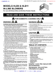
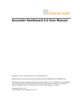
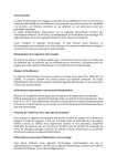
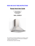
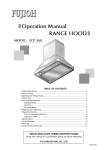
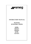
MODEL 808331 Page 1 IN-LINE BLOWER For use with models CTWH30, CTWH36, IH4227, W302418, W302718, W362210-482210 READ AND SAVE THESE INSTRUCTIONS ! FOR DOMESTIC COOKING ONLY ! WARNING WARNING TO REDUCE THE RISK OF FIRE, ELECTRIC SHOCK, OR INJURY TO PERSONS, OBSERVE THE FOLLOWING: 1. Use this unit only in the manner intended by the manufacturer. If you have questions, contact the manufacturer or your distributor. 2. Before servicing or cleaning unit, switch power off at service panel and lock the service disconnecting means to prevent power from being switched on accidentally. When the service disconnecting means cannot be locked, securely fasten a prominent warning device, such as a tag, to the service panel. 3. Installation work and electrical wiring must be done by a qualified person(s) in accordance with all applicable codes and standards, including fire-rated construction codes and standards. 4. Sufficient air is needed for proper combustion and exhausting of gases through the flue (chimney) of fuel burning equipment to prevent backdrafting. Follow the heating equipment manufacturer’s guideline and safety standards such as those published by the National Fire Protection Association (NFPA), and the American Society for Heating, Refrigeration and Air Conditioning Engineers (ASHRAE), and the local code authorities. 5. When cutting or drilling into wall or ceiling, do not damage electrical wiring and other hidden utilities. 6. Ducted fans must always be vented to the outdoors. 7. To reduce the risk of fire, use only steel ductwork. 8. If this unit is to be installed over a tub or shower, it must be marked as appropriate for the application and be connected to a GFCI (Ground Fault Interrupter) - protected branch circuit. 9. Never place a switch where it can be reached from a tub or shower. 10. This unit must be grounded. TO REDUCE THE RISK OF A RANGE TOP GREASE FIRE: 1. Never leave surface units unattended at high settings. Boilovers cause smoking and greasy spillovers that may ignite. Heat oils slowly on low or medium settings. 2. Always turn hood ON when cooking at high heat or when flambeing food (i.e. Crepes Suzette, Cherries Jubilee, Peppercorn Beef Flambe’). 3. Clean ventilating fans frequently. Grease should not be allowed to accumulate on fan or filter. 4. Use proper pan size. Always use cookware appropriate for the size of the surface element. TO REDUCE THE RISK OF INJURY TO PERSONS IN THE EVENT OF A RANGE TOP GREASE FIRE, OBSERVE THE FOLLOWING:* 1. SMOTHER FLAMES with a close-fitting lid, cookie sheet, or metal tray, then turn off the burner. BE CAREFUL TO PREVENT BURNS. If the flames do not go out immediately, EVACUATE AND CALL THE FIRE DEPARTMENT. 2. NEVER PICK UP A FLAMING PAN - You may be burned. 3. DO NOT USE WATER, including wet dishcloths or towels - violent steam explosion will result. 4. Use an extinguisher ONLY if: A. You know you have a Class ABC extinguisher and you already know how to operate it. B. The fire is small and contained in the area where it started. C. The fire department is being called. D. You can fight the fire with your back to an exit. * Based on “Kitchen Fire Safety Tips” published by NFPA. CAUTION ! 1. For general ventilating use only. Do not use to exhaust hazardous or explosive materials and vapors. 2. To avoid motor bearing damage and noisy and/or unbalanced impellers, keep drywall spray, construction dust, etc. off power unit. 3. If ventilator is installed in an unconditioned space (such as an attic): Surround the ventilator with thermal insulation - to minimize possible condensation. 4. Please read specification label on product for further information and requirements. TABLE OF CONTENTS This manual is divided into sections as follows: “TYPICAL INSTALLATION” This section shows a common installation. - Mounting (New Frame Construction) - Mounting (Existing Frame Construction) - Mounting Using Hanger Kit (included) - Ducting (Horizontal blower discharge) - Wiring “MOUNTING OPTIONS” “WIRING PLATE POSITION” “DUCTING OPTIONS” - Blower Discharge Positions - Ducting (Vertical blower discharge) “ATTACH POWER CORD TO HOOD” “USE AND CARE” Installer: Leave this manual with the homeowner. Homeowner: Use and Care information on page 4. Page 2 TYPICAL INSTALLATION TYPICAL INSTALLATION MOUNTING (New Frame Construction) MOUNTING USING HANGER KIT (included) 10” ROUND DUCT 4½” X 18½” TO 10” ROUND TRANSITION Mounting brackets factory-shipped in position for ½” ceiling material. CEILING JOIST (24” centers shown) HANGER KIT BOLT & WASHER EXTENSION SPRING HANGER KIT CHAIN 10” ROUND DUCT (INTAKE) HANGER KIT EYE-BOLT 10” ROUND DUCT Blower factory-shipped in horizontal discharge position. 4½” X 18½” TO 10” ROUND TRANSITION 4½” X 18½” TO 10” ROUND TRANSITION MOUNTING SCREW Factory-shipped unit installed in new construction. MOUNTING BRACKET 4½” X 18½” TO 10” ROUND TRANSITION 4½” X 18½” TO 10” ROUND TRANSITION 10” ROUND DUCT GRILLE NUT (Install into square holes in housing) 10” ROUND DUCT (OUTLET) MOUNTING (Existing Frame Construction) 2 X 4 FRAMING (wide side down) HANGER KIT NUT & WASHER Blower factory-shipped in straight-through discharge position. DUCTING (Horizontal blower discharge) 10” ROUND DUCT ROOF CAP 10” ROUND DUCT 4½” X 18½” TO 10” ROUND TRANSITION MOUNTING SCREW MOUNTING BRACKETS (Attached to opposite sides of housing & upside-down, so housing is flush with finished ceiling) ACCESS PANEL SCREW ACCESS PANEL CEILING JOIST (24” centers shown) Blower factory-shipped in straight-through discharge position. 10” ROUND DUCT 10” ROUND ELBOW WALL CAP Two ways to connect ductwork to a factory-shipped unit. IMPORTANT: Remove shipping tape from damper Remove the shipping tape from the damper flap and make sure that damper flap opens and closes freely inside the ductwork. Use duct tape to make ductwork connections secure and air-tight. Page 3 WIRING PLATE POSITION WIRING BLACK TO BLACK TOP / BACK OF HOUSING VERTICAL POWER CABLE CONNECTION GROUND TO WIRING PLATE WIRING PLATE HORIZONTAL POWER CABLE CONNECTION 120 VAC LINE IN (from range hood) WHITE TO WHITE Ventilator can be wired from outside of housing. Use UL approved connectors to wire per local codes. MOUNTING OPTIONS Wiring plate mounts to side or top of housing. DUCTING OPTIONS BLOWER DISCHARGE POSITIONS ¼-20 hex nuts secure mounting brackets to housing. Loosen and re-tighten or remove and replace nuts as necessary for desired mounting bracket position. DUCT CONNECTOR 1½" to 2½" 11/ 8" MAX. 21½" DUCT CONNECTOR Change blower & duct connector positions for vertical discharge. 21½" INSTALLATION FROM ABOVE FINISHED CEILING ADUSTABLE FOR VARIOUS CEILING THICKNESSES Mounting brackets in factory-shipped position. (Outlet parallel to joists.) (New construction) Mounting brackets flipped over and mounted to outlet sides of housing. (Outlet parallel to joists.) (Existing construction) 11/ 2" to 21/ 2" BLOWER BLOWER Blower and duct connector in horizontal discharge position. (Factory shipped) Blower and duct connector in vertical discharge position. 12¼" 21½" INSTALLATION WITH DUCTWORK RUNNINGbrackets ACROSS mounted JOISTS ADUSTABLE Mounting FOR VARIOUS CEILING THICKNESSES Mounting brackets flipped to outlet sides of housing. (Outlet perpendicular to joists.) (New construction) over to give approx. 1” more clearance. (Outlet parallel to joists.) (New construction) 10 3/ 4" to 11 3/ 4" 91/ 2" to 101/ 2" 21½" DUCTING (Vertical blower discharge) ROOF CAP 10” ROUND DUCT 4½” X 18½” TO 10” ROUND TRANSITION 21½" ADUSTABLE FOR VARIOUS CEILING THICKNESSES ADUSTABLE FOR VARIOUS Mounting bracketsCEILING flippedTHICKNESSES Mounting brackets mounted to top of sides of housing. (Outlet parallel to joists.) (New or existing construction) over and mounted to top of sides of housing. (Outlet parallel to joists.) (New or existing construction) Typical ductwork connection to a ventilator converted to vertical discharge. Page 4 ATTACH POWER CORD TO HOOD Follow wiring instructions packed with range hood, and adhere to all local and state codes, and the National Electrical Code. WARNING: To reduce the risk of electric shock, disconnect from power supply before servicing. USE AND CARE To clean blower assembly: Remove access panel, unplug blower from housing, remove blower mounting nuts, and carefully remove blower from housing. Use appropriate vacuum attachment or a soft cloth and mild soap or detergent to clean blower discharge area and wheel. DO NOT ALLOW WATER TO ENTER MOTOR. Make sure blower assembly is completely dry before reinstalling. Motor is permanently lubricated. Do not oil or disassemble motor. Some hoods require the use of a separate power cord and strain relief bushing (included), for proper wiring of in-line blowers. Please refer to the hood manual for proper installation instructions. 99043889B MODEL 808332 Page 1 IN-LINE BLOWER For use with models CTWH30, CTWH36, IH4227, DD30R, DD36R, DD45R, W30-662418, W30-662718, L28-582212, I36-663418 READ AND SAVE THESE INSTRUCTIONS ! FOR DOMESTIC COOKING ONLY ! WARNING WARNING TO REDUCE THE RISK OF FIRE, ELECTRIC SHOCK, OR INJURY TO PERSONS, OBSERVE THE FOLLOWING: 1. Use this unit only in the manner intended by the manufacturer. If you have questions, contact the manufacturer or your distributor. 2. Before servicing or cleaning unit, switch power off at service panel and lock the service disconnecting means to prevent power from being switched on accidentally. When the service disconnecting means cannot be locked, securely fasten a prominent warning device, such as a tag, to the service panel. 3. Installation work and electrical wiring must be done by a qualified person(s) in accordance with all applicable codes and standards, including fire-rated construction codes and standards. 4. Sufficient air is needed for proper combustion and exhausting of gases through the flue (chimney) of fuel burning equipment to prevent backdrafting. Follow the heating equipment manufacturer’s guideline and safety standards such as those published by the National Fire Protection Association (NFPA), and the American Society for Heating, Refrigeration and Air Conditioning Engineers (ASHRAE), and the local code authorities. 5. When cutting or drilling into wall or ceiling, do not damage electrical wiring and other hidden utilities. 6. Ducted fans must always be vented to the outdoors. 7. To reduce the risk of fire, use only steel ductwork. 8. If this unit is to be installed over a tub or shower, it must be marked as appropriate for the application and be connected to a GFCI (Ground Fault Interrupter) - protected branch circuit. 9. Never place a switch where it can be reached from a tub or shower. 10. This unit must be grounded. TO REDUCE THE RISK OF A RANGE TOP GREASE FIRE: 1. Never leave surface units unattended at high settings. Boilovers cause smoking and greasy spillovers that may ignite. Heat oils slowly on low or medium settings. 2. Always turn hood ON when cooking at high heat or when flambeing food (i.e. Crepes Suzette, Cherries Jubilee, Peppercorn Beef Flambe’). 3. Clean ventilating fans frequently. Grease should not be allowed to accumulate on fan or filter. 4. Use proper pan size. Always use cookware appropriate for the size of the surface element. TO REDUCE THE RISK OF INJURY TO PERSONS IN THE EVENT OF A RANGE TOP GREASE FIRE, OBSERVE THE FOLLOWING:* 1. SMOTHER FLAMES with a close-fitting lid, cookie sheet, or metal tray, then turn off the burner. BE CAREFUL TO PREVENT BURNS. If the flames do not go out immediately, EVACUATE AND CALL THE FIRE DEPARTMENT. 2. NEVER PICK UP A FLAMING PAN - You may be burned. 3. DO NOT USE WATER, including wet dishcloths or towels - violent steam explosion will result. 4. Use an extinguisher ONLY if: A. You know you have a Class ABC extinguisher and you already know how to operate it. B. The fire is small and contained in the area where it started. C. The fire department is being called. D. You can fight the fire with your back to an exit. * Based on “Kitchen Fire Safety Tips” published by NFPA. CAUTION ! 1. For general ventilating use only. Do not use to exhaust hazardous or explosive materials and vapors. 2. To avoid motor bearing damage and noisy and/or unbalanced impellers, keep drywall spray, construction dust, etc. off power unit. 3. If ventilator is installed in an unconditioned space (such as an attic): Surround the ventilator with thermal insulation - to minimize possible condensation. 4. Please read specification label on product for further information and requirements. TABLE OF CONTENTS This manual is divided into sections as follows: “TYPICAL INSTALLATION” This section shows a common installation. - Mounting (New Frame Construction) - Mounting (Existing Frame Construction) - Mounting Using Hanger Kit (included) - Ducting (Horizontal blower discharge) - Wiring “MOUNTING OPTIONS” “WIRING PLATE POSITION” “DUCTING OPTIONS” - Blower Discharge Positions - Ducting (Vertical blower discharge) “ATTACH POWER CORD TO HOOD” “USE AND CARE” Installer: Leave this manual with the homeowner. Homeowner: Use and Care information on page 4. Page 2 TYPICAL INSTALLATION TYPICAL INSTALLATION MOUNTING (New Frame Construction) MOUNTING USING HANGER KIT (included) 10” ROUND DUCT (OUTLET) 8” X 12” TO 10” ROUND TRANSITION (MALE) 8” X 12” TO 10” ROUND TRANSITION (FEMALE) 10” ROUND DUCT (INTAKE) MOUNTING BRACKETS Ventilator factory-shipped in straight-through discharge position. EXTENSION SPRING HANGER KIT CHAIN 8” X 12” TO 10” ROUND TRANSITION (MALE) HANGER KIT NUT & WASHER MOUNTING BRACKET GRILLE NUT (Install into square holes in housing) ACCESS PANEL 10” ROUND DUCT (OUTLET) MOUNTING (Existing Frame Construction) 8” X 12” TO 10” ROUND TRANSITION (MALE) 10” ROUND DUCT (INTAKE) CEILING JOIST (24” centers shown) Factory-shipped unit installed in new construction. 8” X 12” TO 10” ROUND TRANSITION (FEMALE) HANGER KIT BOLT & WASHER HANGER KIT EYE-BOLT GRILLE NUT (Install into square holes in housing) ACCESS PANEL SCREW 8” X 12” TO 10” ROUND TRANSITION (FEMALE) 10” ROUND DUCT (INTAKE) Blower factory-shipped in straight-through discharge position. MOUNTING BRACKETS DUCTING (Horizontal blower discharge) 10” ROUND DUCT (OUTLET) ROOF CAP MOUNTING SCREWS CEILING JOIST (24” centers shown) Ventilator factory-shipped ACCESS in straight-through PANEL SCREW discharge position. ACCESS PANEL SCREW ACCESS PANEL GRILLE NUT (Install into square holes in housing) 10” ROUND DUCT 8” X 12” TO 10” ROUND TRANSITION (MALE) 10” ROUND DUCT ACCESS PANEL Factory-shipped unit installed in existing construction. 8” X 12” TO 10” ROUND TRANSITION (FEMALE) 10” ROUND ELBOW WALL CAP Two ways to connect ductwork to a factory-shipped unit. IMPORTANT: Remove shipping tape from damper Remove the shipping tape from the damper flap and make sure that damper flap opens and closes freely inside the ductwork. Use duct tape to make ductwork connections secure and air-tight. Page 3 WIRING WIRING PLATE POSITION BLACK TO BLACK EDGE OF HOUSING GROUND TO WIRING PLATE VERTICAL POWER CABLE CONNECTION WIRING PLATE HORIZONTAL POWER CABLE CONNECTION WHITE TO WHITE Wiring plate mounts to side or top of housing. 120 VAC LINE IN (from range hood) DUCTING OPTIONS Ventilator can be wired from outside of housing. Use UL approved connectors to wire per local codes. BLOWER DISCHARGE POSITIONS MOVABLE PANEL MOUNTING OPTIONS ¼-20 hex nuts secure mounting brackets to housing. Loosen and re-tighten or remove and replace nuts as necessary for desired mounting bracket position. Factory-Shipped Straight-Through Discharge 11/ 8" MAX. Factory-Shipped Straight-Through Discharge 22" 1½" to 2½" 18" ADUSTABLE FOR VARIOUS CEILING Mounting Mounting brackets in THICKNESSES factory-shipped position mounted directly to joists. (Outlet parallel to joists.) (New construction) brackets flipped over and mounted to additional framing. DUCT DUCT Housing CONNECTOR rotated & mov- CONNECTOR (outlet) (outlet) able panel covers previous open side. DUCT CONNECTOR (intake) Ventilator shown in straight-through discharge position. (Factory shipped) (Outlet perpendicular to joists.) (New or Existing construction) MOVABLE PANEL (Change to this DUCT location) CONNECTOR (intake) Ventilator shown in rightangle discharge position. (Change movable panel to new location as shown.) DUCTING (Vertical blower discharge) Housing Converted to RightAngle Discharge 18" 1½" to 2½" Factory-Shipped Straight-Through Discharge 22" 8” X 12” TO 10” ROUND TRANSITION (MALE) 8” X 12” TO 10” ROUND TRANSITION (FEMALE) ROOF CAP 10” ROUND DUCT FOR brackets VARIOUS CEILING Mounting flipped THICKNESSES Mounting brackets flippedADUSTABLE 10” ROUND over and mounted to top of over and mounted to adDUCT housing. Housing secured ditional framing. (Outlet vertical.) with cables. (New or Existing construction) Typical ductwork connection to a ventilator converted to (Outlet parallel to joists.) (New or Existing construction) right-angle discharge. Page 4 ATTACH POWER CORD TO HOOD Follow wiring instructions packed with range hood, and adhere to all local and state codes, and the National Electrical Code. WARNING: To reduce the risk of electric shock, disconnect from power supply before servicing. USE AND CARE To clean blower assembly: Remove access panel, unplug blower from housing, remove blower mounting nuts, and carefully remove blower from housing. Use appropriate vacuum attachment or a soft cloth and mild soap or detergent to clean blower discharge area and wheel. DO NOT ALLOW WATER TO ENTER MOTOR. Make sure blower assembly is completely dry before reinstalling. Motor is permanently lubricated. Do not oil or disassemble motor. Some hoods require the use of a separate power cord and strain relief bushing (included), for proper wiring of in-line blowers. Please refer to the hood manual for proper installation instructions. 99043890C