1
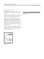
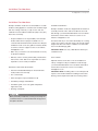
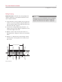
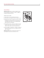
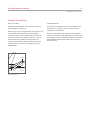
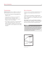
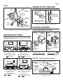
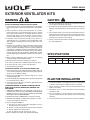
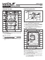
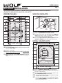
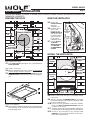
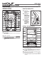
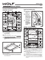
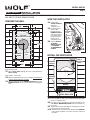
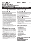
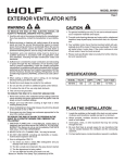
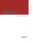
INSTALLATION GUIDE Pro Island Ventilation Hoods READ AND SAVE THESE INSTRUCTIONS Contents Important Note Wolf Pro Island Ventilation Hoods. . . . . . . . . . . . . . . . . 3 To ensure the safe and efficient use of Wolf equipment, please take note of the following types of highlighted information throughout this guide: Safety Instructions . . . . . . . . . . . . . . . . . . . . . . . . . . . . 4 Installation Considerations . . . . . . . . . . . . . . . . . . . . . . 5 Pro Island Hood Specifications . . . . . . . . . . . . . . . . . . 6 Pro Island Hood Installation . . . . . . . . . . . . . . . . . . . . . 8 Service Information . . . . . . . . . . . . . . . . . . . . . . . . . . . 18 Features and specifications are subject to change at any time without notice. Visit wolfappliance.com/specs for the most up-to-date information. IMPORTANT NOTE: Throughout this guide, dimensions in parentheses are millimeters unless otherwise specified. IMPORTANT NOTE highlights information that is especially important. CAUTION signals a situation where minor injury or product damage may occur if instructions are not followed. WARNING states a hazard that may cause serious injury or death if precautions are not followed. Wolf Pro Island Ventilation Hoods 3 wolfappliance.com/specs Pro Island Hood Installation IMPORTANT NOTE: This installation must be completed by a qualified installer or Wolf authorized service center technician. Read this entire installation guide prior to installation and save for the local inspector’s reference. The homeowner should keep this installation guide for future reference. This appliance must be installed in accordance with National Electrical Codes, as well as all state, municipal and local codes. The correct voltage, frequency and amperage must be supplied to the appliance from a dedicated, grounded circuit which is protected by a properly sized circuit breaker or time delay fuse. The proper voltage, frequency, and amperage ratings are listed on the product rating plate. Record the model and serial numbers before installing the ventilation hood. Both numbers are listed on the product rating plate, located inside the left wall of the hood shell. Refer to the illustration below. RATING PLATE Location of rating plate (inside hood). Wolf Pro Island Hood Model Number Serial Number Safety Instructions 4 IMPORTANT INSTRUCTIONS TO REDUCE THE RISK OF FIRE, ELECTRIC SHOCK OR INJURY, OBSERVE THE FOLLOWING: • Installation work and electrical wiring must be done by qualified person(s) in accordance with all applicable codes and standards, including fire-rated construction. • Two installers are recommended due to the size and weight of the pro ventilation hood. • Install the pro ventilation hood only with a blower manufactured by Wolf. • When cutting or drilling into wall or ceiling, do not damage electrical wiring and other hidden utilities. TO REDUCE RISK OF RANGE TOP GREASE FIRE: A) Never leave surface units unattended at high settings. Boilovers cause smoking and greasy spillovers that may ignite. Heat oils slowly on low or medium settings. B) Always turn the ventilation hood on when cooking at high heat or when flambeing foods such as crepes suzette or cherries jubilee. C) Clean ventilation fans frequently. Grease should not be allowed to accumulate on fan or filter. D) Use proper pan size. Always use cookware appropriate for the size of the surface burner. • Ducted fans must always be vented to the outdoors. To reduce the risk of fire and properly exhaust air, be certain to duct air outside. Do not vent exhaust air into spaces within walls or ceilings or into attics, crawl spaces or garages. The hood motor has a thermal overload which will automatically shut off the motor if it becomes overheated. The motor will restart when it has cooled down. If the motor continues to shut off and restart, have the hood serviced. TO REDUCE THE RISK OF INJURY TO PERSONS IN THE EVENT OF A RANGE TOP GREASE FIRE, OBSERVE THE FOLLOWING: • Smother flames with close-fitting lid, cookie sheet, or metal tray, then turn off the burner. Be careful to prevent burns. If the flames do not go out immediately, evacuate and call the fire department. • Never pick up a flaming pan—you may be burned. • Do not use water, including wet dishcloths or towels —a violent steam explosion will result. USE AN EXTINGUISHER ONLY IF: • You know you have a class ABC extinguisher and you already know how to operate it. • The fire is small and contained in the area where it started. • The fire department is being called. • You can fight the fire with your back to an exit (NFPA fire safety tips). Installation Considerations 5 wolfappliance.com/specs Installation Considerations Wolf pro ventilation hoods are recommended for use with all Wolf cooking appliances. Island hoods should be larger than the cooking surface by 3" (76) on each side. The ventilation hood should be installed 30" (762) to 36" (914) above the countertop. • Proper installation is the responsibility of the installer. Product failure due to improper installation is not covered under the Wolf warranty. Refer to the Wolf pro ventilation hoods use & care guide for warranty details, or visit the contact & support section of our website, wolfappliance.com. • Make sure you have the tools and materials necessary for proper installation. • Warranty service must be performed by a Wolf authorized service center. Wolf is not responsible for service required to correct a faulty installation. MATERIALS INCLUDED WITH HOOD: • Transition with backdraft damper—attached inside hood (needs to be removed) • Two control knobs • Filters and grease cups (installed in hood) • Installation package and hardware • Installation guide, use & care guide and product registration card • Wolf logo nameplate When performing installation, servicing or cleaning the ventilation hood, it is recommended that safety glasses and gloves be worn. BLOWER ASSEMBLIES Wolf pro ventilation hoods are shipped without the blower assembly. Internal, in-line and remote blowers are available through your authorized Wolf dealer. For local dealer information, visit the find a showroom section of our website, wolfappliance.com. The blower will vary in size and is dictated by the cooking surface, the volume of air that needs to be moved and the length of the duct run. Refer to ventilation recommendations in the Wolf design guide. IMPORTANT NOTE: Use only a Wolf blower with the pro ventilation hood. DUCT COVER Optional stainless steel duct covers are available in a variety of heights for all pro ventilation hoods through your authorized Wolf dealer. For local dealer information, visit the find a showroom section of our website, wolfappliance.com. IMPORTANT NOTE: Installing a duct cover will impact all aspects of the hood installation including hood location, ducting, electrical placement and the mounting surface. Pro Island Hood Specifications 6 Overall Dimensions PRO ISLAND HOODS WIDTH MINUS 18" (457) 13" (330) 18" (457) OVERALL HEIGHT 4" (102) 36" (914), 42" (1067), 54" (1372) AND 66" (1676) WIDTHS 34" (864) OVERALL DEPTH Installation Specifications PRO ISLAND HOODS LOCATION OF ELECTRICAL THROUGH TOP OF HOOD 18" (457) HEIGHT OF HOOD 34" (864) DEPTH OF HOOD WIDTH OF HOOD 30" (762) TO 36" (914) TO COUNTERTOP Pro Island Hood Specifications 7 wolfappliance.com/specs Installation Specifications Electrical Requirements The illustration below provides dimensions critical for proper installation of the pro island hood. Dimensions A and B in the illustration will vary with the width of the hood. Refer to the chart below. Wolf pro ventilation hoods require a separate, grounded 120 V AC, 60 Hz power supply. The service should have its own 15 amp circuit breaker. Locate the electrical supply in the ceiling through the top of the island hood. Refer to the installation specifications illustration on the previous page. Pro Island Hoods WIDTH OF HOOD 36" (914) 42" (1067) 54" (1371)* 66" (1676)* A B 18" (457) 24" (610) 36" (914) 48" (1219) 9" (228) 12" (304) 18" (457) 24" (610) A WIDTH OF TOP PLATE 10" (254) 7" 61/2" 13" (165) (330) (178) B TO CENTER OF TRANSITION Pro island hoods. IMPORTANT NOTE: You must follow all National Electrical Code regulations. In addition, be aware of local codes and ordinances when installing your service. Risk of electrical shock. This ventilation hood must be properly grounded. Electrical service for the hood must be installed by a qualified electrician in accordance with all applicable national and local electrical codes. Pro Island Hood Installation 8 Install Ductwork PRO ISLAND HOODS To reduce the risk of fire, use only metal ductwork. IMPORTANT NOTE: Pro ventilation hoods must exhaust to the outdoors. Wolf recommends that the pro island hood be installed 30" (762) to 36" (914) above the countertop. Consult a qualified HVAC engineer for specific ducting applications. DUCTWORK INSTALLATION THROUGH ROOF A 10" (254) round duct is recommended for pro ventilation hoods. Use only rigid metal ductwork, do not use flex ducting. Decide where the ductwork will run between the island hood and the outside. Pro island hoods have a vertical discharge. A straight, short duct run will allow the ventilation hood to perform most efficiently. Limit the number of elbows and transitions. The duct run should be no longer than 50' (15 m). There is a possibility of noise issues, if a remote blower is used with a short duct run. 13" 18" (457) HOOD HEIGHT 4" (102) 34" (864) HOOD DEPTH 30" (762) TO 36" (914) Unless you are using a remote blower, a roof or wall cap must be installed. Connect 10" (254) round metal ductwork to the cap and work back towards the hood. Use duct sealing tape to seal joints between ductwork sections. Pro island hoods have a backdraft damper included in the transition assembly. Local codes may require the use of an additional backdraft damper. Contact your local HVAC professional for specific requirements. In cold weather installations, a backdraft damper is necessary to minimize the backflow of cold air into the room. Local building codes may require the use of make-up air. Consult your local HVAC professional for specific requirements in your area. (330) BOTTOM OF HOOD TO COUNTERTOP Pro Island Hood Installation 9 wolfappliance.com/specs Ceiling Framing IMPORTANT NOTE: A minimum 10" (254) opening in the ceiling is required to accommodate the ductwork necessary for proper ventilation. 1) Layout dimensions of the top plate of the hood (or top of duct cover) on the ceiling. The top plate dimensions will vary with the width of the island hood. Refer to the illustration and chart on page 7. 2) Construct the ceiling framing using minimum 2" x 4" lumber. Proper structural support is required to accommodate the weight of the hood. 3) Mark the center location of the hood. Install 2" x 4" blocking between ceiling joists. Refer to the illustration below. 4) Drill four 5/32" diameter holes in the framing to match mounting holes in the top plate of the hood (or top of duct cover). WIDTH OF TOP PLATE 13" (330) DEPTH OF TOP PLATE MOUNTING HOLES Ceiling framing. 2" X 4" BLOCKING Framing must be fastened together and to ceiling joists to provide enough structural strength to support the weight of the hood and internal blower, if applicable. Pro Island Hood Installation 10 Duct Cover IMPORTANT NOTE: If an optional duct cover is to be used with the pro island hood, it must be attached before installing the hood. Installing a duct cover will impact all aspects of the hood installation, including hood location, ducting, electrical placement and the mounting surface. DUCT COVER INSTALLATION 1) Use the four 1/4" x 3" (76) lag screws and washers (provided with hood) to attach the duct cover to ceiling framing. The width of the duct cover should be the same as the top plate of the island hood. Refer to the illustration and chart on page 7. 2) Install additional #10 x 2" (51) hex head screws (provided with hood) along the top edge of the duct cover for support. Refer to the illustration below. 3) Proceed with hood preparation and installation. HEX HEAD SCREWS DUCT COVER LAG SCREWS Duct cover installation. Pro Island Hood Installation 11 wolfappliance.com/specs Hood Preparation 1) Remove the filters of the pro island hood by pushing each filter up at the angle it is placed in, and rotate the bottom of the filter down. Refer to the illustration below. Gloves should be worn when handling filters. 2) Slide the grease cups out from the bottom edges of the front and back of the hood. 3) Using a Phillips screwdriver, remove the screws retaining the hood’s internal frame shown in the shaded area of the illustration below. Be sure to leave the other two screws in place. Do not discard the screws. They will be used to reinstall the internal frame after installation is complete. Remove the internal frame from the hood and set aside. FILTER DO NOT REMOVE Remove filters. REMOVE SCREWS Internal frame. DO NOT REMOVE 4) The hood assembly is shipped with the transition attached. The transition is shipped upside down in the top of the hood and must be removed and reinstalled in the proper position. Separate the transition from the hood assembly by removing the four shipping screws. Invert and reattach the transition to the hood with the shipping screws. 5) If you are installing an in-line or remote blower, punch out the knockout hole located on the top of the hood. Install a wire clamp (provided with hood) for the remote blower cable. Install another wire clamp in the hole on top of the hood for the Romex® wire. Refer to the inline and remote blowers section on page 16 and follow installation instructions provided with the blower. Pro Island Hood Installation 12 Hood Installation INSTALLATION WITHOUT DUCT COVER Due to the weight of the hood, be sure to have adequate assistance for installation. IMPORTANT NOTE: If an optional duct cover is to be used, it must be installed before installing the island hood. Refer to duct cover installation on page 10. The filters and internal frame must be removed from the hood prior to installation. Refer to hood preparation on the previous page. INSTALLATION WITH DUCT COVER 1) If a duct cover has been installed, install the four 5/16" bolts (provided with duct cover) through the mounting holes on each corner of the hood and into the bottom edge of the duct cover. Attach the duct cover to the hood assembly with the #12 x 7/8" (22) self-tapping hex head screws (provided with duct cover). Refer to the illustration below. 1) Lift the hood and align the hood mounting holes with the predrilled holes in the ceiling framing. Install the four 1/4" x 3" (76) lag screws with the washers (provided with hood) through the mounting holes on each corner of the island hood and into framing. Do not overtighten screws. 2) Connect the 10" (254) round ductwork to the transition using sheet metal screws and duct sealing tape. 3) Adjust the positioning of the hood if necessary, and tighten the four lag screws until the hood is flush with the ceiling. Install additional #10 x 2" (51) hex head screws (provided with hood) through the remaining mounting holes in the top plate of the hood for additional support. Refer to the illustration below. 4) If you are installing an internal blower, do not reinstall the internal frame and filters until blower installation is complete. Refer to internal blower information on page 15. 5) Proceed with hood wiring connections. 2) Connect the 10" (254) round ductwork to the transition using sheet metal screws and duct sealing tape. 3) If you are installing an internal blower, do not reinstall the internal frame and filters until blower installation is complete. Refer to internal blower information on page 15. HEX HEAD SCREW LAG SCREW 4) Proceed with hood wiring connections. DUCT COVER NUT Installation without duct cover. 5/16" BOLT HEX HEAD SCREW Installation with duct cover. Pro Island Hood Installation 13 wolfappliance.com/specs Blower Assemblies Internal Blower Pro ventilation hoods are shipped without the blower assembly. Internal, in-line and remote blowers are available through your authorized Wolf dealer. For local dealer information, visit the find a showroom section of our website, wolfappliance.com. WIRING FOR INTERNAL BLOWER The blower will vary in size and is dictated by the cooking surface, the volume of air that needs to be moved and the length of the duct run. Refer to ventilation recommendations in the Wolf design guide. IMPORTANT NOTE: Use wire connectors or wire nuts approved by UL or C/UL. To reduce the risk of fire and electric shock, install this ventilation hood only with a blower manufactured by Wolf. Before making electrical connections, make sure the electrical power is turned off at the service panel. 1) Remove the hood electrical box cover. Run Romex® wire from a 120 V AC, 15 amp circuit to the hood installation location. Insert the Romex® wire into the electrical box by running it through the wire clamp previously installed. Tighten the wire clamp to secure the wire. Refer to the illustration and chart below for the location of wiring for your specific hood. Do not remove the wire connector on the orange wire in the hood electrical box. 2) Using the wire connectors provided, connect black wire to power supply black wire, white wire to power supply white wire and green or bare wire from power supply to green ground screw in the electrical box. 3) Place all wiring connections inside the electrical box and reinstall the cover. Make sure all wires are secure and that no wires are pinched between the cover and electrical box. Location of Hood Wiring WIDTH OF HOOD A 36" (914) 42" (1067) 54" (1371) 66" (1676) 2" (51) 3" (76) 4" (102) 4" (102) 11/2" (38) A 2" (51) Location of hood wiring. Pro Island Hood Installation 14 Internal Blower IMPORTANT NOTE: Refer to specific installation instructions provided with each blower assembly for additional mounting and wiring instructions. THREADED STUD SLOT BLOWER INSTALLATION TAB 1) Discard the hex nuts provided with the blower. 2) Lift the blower assembly into position inside the hood. 3) Engage the two tabs on the blower into the two slots in the top plate of the island hood. Secure the blower to the threaded studs with two hex nuts (provided with blower). Refer to the illustration. 5) Plug the blower power cords into receptacles located near the center of the hood shell. Use the clips on the interior of the hood to secure excess power cord. 6) Once installation of the blower is complete, reinstall the internal frame and filters. Refer to complete the installation on page 17. IMPORTANT NOTE: Before turning electrical power on to the ventilation hood, make sure the blower is off. HEX NUT Internal blower. Pro Island Hood Installation 15 wolfappliance.com/specs In-Line and Remote Blowers WIRING FOR IN-LINE OR REMOTE BLOWER 1) Remove the hood electrical box cover. Run Romex® wire from a 120 V AC, 15 amp circuit to the hood installation location. Insert the Romex® wire into the electrical box by running it through the wire clamp previously installed. Tighten the wire clamp to secure the wire. Refer to the illustration and chart on the previous page for the location of wiring for your specific hood. 2) Run the blower cable to the installation location. Insert the blower cable into the electrical box by running it through the other wire clamp previously installed. Tighten the wire clamp to secure the cable. 3) Cut off the butt crimp connector from the end of orange wire in hood. Strip orange wire about 3/8" (10). Using an appropriate wire connector (not included), connect black wire from blower to orange wire in hood. 4) Using the wire connectors provided, connect black wire to power supply black wire, all white wires together and green or bare wires from power supply and blower to green ground screw in the electrical box. 5) Place all wiring connections inside the electrical box and reinstall the cover. Make sure all wires are secure and that no wires are pinched between the cover and electrical box. Before making electrical connections, make sure the electrical power is turned off at the service panel. Do not run wiring through the ductwork. Pro Island Hood Installation 16 In-Line and Remote Blowers Allow enough space for transitions needed between the blower and connecting ductwork. For best performance, locate transitions nearest the blower. BLOWER INSTALLATION IMPORTANT NOTE: Refer to specific installation instructions provided with each blower assembly for additional mounting and wiring instructions. Locate the blower so that the length of the duct run and number of elbows and transitions are kept to a minimum. The duct run should be no longer than 50' (15 m). Remote blowers should be located between wall studs or roof rafters. Avoid pipes, wires and other ductwork. Refer to the illustrations below for overall dimensions of Wolf in-line and remote blowers. Installation instructions shipped with each Wolf ventilation product provide detailed specifications. These instructions can also be found on our website, wolfappliance.com/specs. Before making electrical connections, make sure the electrical power is turned off at the service panel. IN-LINE AND REMOTE BLOWER DIMENSIONS 24 7/8" (632) 18" (457) 12" (305) 8" (203) 22" 18" (559) (457) 1100 CFM in-line blower. 18" (457) 28 1/4" (718) 10" (254) 29 1/2" (749) 10" (254) DIAMETER DIAMETER 14 3/4" 15 1/2" 24 1/2" 29 1/2" (375) (254) 29 1/2" (749) 10" (254) (394) 21" (533) 10" 20 3/4" (527) (749) 10" (254) DIAMETER 14 3/4" 29 1/2" (375) (749) (622) 10 1/8" 14" 10 3/8" (257) (356) 4 3/4" 24 3/4" (629) 900 CFM remote blower. (121) (264) 22" (559) 1200 CFM remote blower. 7 1/4" 25" 7 1/4" (184) (635) (184) 1500 CFM remote blower. Pro Island Hood Installation 17 wolfappliance.com/specs Complete the Installation INSTALL FILTERS LOGO NAMEPLATE Reinstall the internal frame on the island hood. Refer to hood preparation on page 11. The Wolf logo nameplate does not come installed on the island hood since there are various locations that the nameplate can be attached. Slide the grease cups along the bottom edge of the hood so that the lip of the grease cup overhangs slightly. To install the filters, orient each filter with lines running vertically. Position the top edge of the filter as shown in the illustration below. While pressing up against the spring, rotate the bottom edge of the filter into position next to the grease cup. Gloves should be worn when handling filters. SPRING FILTER GREASE CUP Filter installation. SIDE VIEW Once you've decided on the location for the nameplate, clean the mounting area with rubbing alcohol. Remove the backing paper from the nameplate. Position the nameplate aligned parallel with the bottom edge of the hood and press into place. Service Information 18 Troubleshooting Service Information IMPORTANT NOTE: If the pro ventilation hood does not operate properly, follow these troubleshooting steps: If service is necessary, maintain the quality built into your ventilation hood by calling a Wolf authorized service center. • Verify that electrical power is being supplied to the ventilation hood. • Check electrical connections to ensure that the installation has been completed correctly. • Refer to the troubleshooting guide in the Wolf pro ventilation hoods use & care guide. • If the ventilation hood still does not operate properly, contact a Wolf authorized service center. Do not attempt to repair the ventilation hood yourself. Wolf is not responsible for service required to correct a faulty installation. To obtain the name and number of a Wolf authorized service center, check the contact & support section of our website, wolfappliance.com or call Wolf customer service at 800-332-9513. When calling for service, you will need the model and serial numbers of the ventilation hood. This information is found on the product rating plate, located inside the left wall of the hood shell. Refer to the illustration below. Before servicing or cleaning, switch power off at the service panel and lock the service disconnecting means to prevent power from being switched on accidentally. If it cannot be locked, securely fasten a prominent warning tag, to the service panel. RATING PLATE Location of rating plate (inside hood). The information and images in this guide are the copyright property of Wolf Appliance, Inc. Neither this guide nor any information or images contained herein may be copied or used in whole or in part without the express written permission of Wolf Appliance, Inc. ©Wolf Appliance, Inc. all rights reserved. Wolf, Wolf & Design, Wolf Gourmet, W & Design and the color red as applied to knobs are registered trademarks and service marks of Wolf Appliance, Inc. Sub-Zero, Sub-Zero & Design, Dual Refrigeration, Constant Care and The Living Kitchen are registered trademarks and service marks of Sub-Zero, Inc. (collectively, the “Company Marks.”) All other trademarks or registered trademarks are property of their respective owners in the United States and other countries. WOLF APPLIANCE, INC. P. O. BOX 44848 MADISON, WI 53744 817001 REV-A 8/ 2010 WOLFAPPLIANCE.COM 800.332.9513 MODEL • 814781 INTERIOR VENTILATOR KITS Forusewithhoodmodels: IH4227 CTWH36 WARNING WARNING TO REDUCE THE RISK OF FIRE, ELECTRIC SHOCK, OR INJURY TO PERSONS, OBSERVE THE FOLLOWING: TO REDUCE THE RISK OF A COOKTOP GREASE FIRE: 1. Usethisunitonlyinthemannerintendedbythemanufacturer.If youhavequestions,contactthemanufactureroryourdistributor. 2. Beforeservicingorcleaningunit,switchpoweroffatservice panel and lock the service disconnecting means to prevent powerfrombeingswitchedonaccidentally.Whentheservice disconnecting means cannot be locked, securely fasten a prominentwarningdevice,suchasatag,totheservicepanel. 3. Installationworkandelectricalwiringmustbedonebyaqualified person(s)inaccordancewithallapplicablecodesandstandards, includingfire-ratedconstructioncodesandstandards. 4. Sufficientairisneededforpropercombustionandexhausting ofgasesthroughtheflue(chimney)offuelburningequipment topreventbackdrafting.Followtheheatingequipmentmanufacturer’sguidelinesandsafetystandardssuchasthosepublished by the National Fire ProtectionAssociation (NFPA), and the AmericanSocietyforHeating,RefrigerationandAirConditioningEngineers(ASHRAE),andthelocalcodeauthorities. 1. Neverleavesurfaceunitsunattendedathighsettings.Boilovers causesmokingandgreasyspilloversthatmayignite.Heatoils slowlyonlowormediumsettings. 2. AlwaysturnhoodONwhencookingathighheatorwhencookingflamingfoods. 3. Cleanventilatingfansfrequently.Greaseshouldnotbeallowed toaccumulateonfanorfilter. 4. Useproperpansize.Alwaysusecookwareappropriateforthe sizeofthesurfaceelement. TO REDUCE THE RISK OF INJURY TO PERSONS IN THE EVENT OF A COOKTOP GREASE FIRE, OBSERVE THE FOLLOWING:* 1. SMOTHER FLAMES with a close-fitting lid, cookie sheet, or metaltray,thenturnofftheburner.BECAREFULTOPREVENT BURNS.Iftheflamesdonotgooutimmediately,EVACUATE ANDCALLTHEFIREDEPARTMENT. 2. NEVERPICKUPAFLAMINGPAN-Youmaybeburned. 5. When cutting or drilling into wall or ceiling, do not damage electricalwiringandotherhiddenutilities. 3. DONOTUSEWATER,includingwetdishclothsortowels-violentsteamexplosionwillresult. 6. Ductedfansmustalwaysbeventedtotheoutdoors. 4. UseanextinguisherONLYif: 7. Donotusethisunitwithanadditionalspeedcontroldevice. 8. Toreducetheriskoffire,useonlysteelductwork. A. You know you have a ClassABC extinguisher and you alreadyknowhowtooperateit. 9. Thisunitmustbegrounded. B. Thefireissmallandcontainedintheareawhereitstarted. C.Thefiredepartmentisbeingcalled. D. Youcanfightthefirewithyourbacktoanexit. *Basedon“KitchenFireSafetyTips”publishedbyNFPA. CAUTION ! 1. Forgeneralventilatinguseonly.Donotusetoexhausthazardousorexplosivematerialsandvapors. 2. Toavoidmotorbearingdamageandnoisyand/orunbalanced impellers,keepdrywallspray,constructiondust,etc.offpower unit. 3. Yourventilatormotorhasathermaloverloadwhichwillautomaticallyshutoffthemotorifitbecomesoverheated.Themotorwill restartwhenitcoolsdown.Ifthemotorcontinuestoshutoffand restart,havethehoodserviced. 4. Pleasereadspecificationlabelonproductforfurtherinformation andrequirements. MODEL • 814781 DUAL BLOWER INSTALLATION SINGLE BLOWER INSTALLATION For blower model 814422 For blower models 814419, 814420 & 814421 ADAPTERPLATE MOUNTINGPLATE ADAPTERPLATE CENTER PIECE (4)10-24NUTS (4)10-24NUTS 1. MountblowertoMOUNTING PLATE(providedwithblower) with(4) 10-24 NUTS(provided). 2. RemoveCENTER PIECEofADAPTER PLATE. 3. Mountblower/mountingplateassemblytoADAPTER PLATE using(4) 10-24 NUTS(provided). (8)10-24NUTS 1. Mount blowers to ADAPTER PLATE with (8) 10-24 NUTS (provided). (4)10-24 HEXNUTS HOODTOPPLATE HOODTOPPLATE (4)10-24 HEXNUTS (4)THREADED STUDS POWER CORD 2. Use (4) 10-24 HEX NUTS to attach adapter plate / blower assembly to (4) THREADED STUDS on the HOOD TOP PLATE. 3. Plug blower POWER CORD into the receptacle inside the hood.Routewiresawayfromtheblower'smovingparts.Bundle wireswithwiretie(provided). (4)THREADED STUDS POWER CORD 4. Use (4) 10-24 HEX NUTS to attach adapter plate / blower assemblyto(4) THREADED STUDSonHOOD TOP PLATE. 5. PlugblowerPOWER CORDintoreceptacleinsideofhood. Route wires away from the blower's moving parts. Bundle wireswithwiretie(provided). 99044556A 815070A MODEL 808331 Page 1 IN-LINE BLOWER For use with models CTWH30, CTWH36, IH4227, W302418, W302718, W362210-482210 READ AND SAVE THESE INSTRUCTIONS ! FOR DOMESTIC COOKING ONLY ! WARNING WARNING TO REDUCE THE RISK OF FIRE, ELECTRIC SHOCK, OR INJURY TO PERSONS, OBSERVE THE FOLLOWING: 1. Use this unit only in the manner intended by the manufacturer. If you have questions, contact the manufacturer or your distributor. 2. Before servicing or cleaning unit, switch power off at service panel and lock the service disconnecting means to prevent power from being switched on accidentally. When the service disconnecting means cannot be locked, securely fasten a prominent warning device, such as a tag, to the service panel. 3. Installation work and electrical wiring must be done by a qualified person(s) in accordance with all applicable codes and standards, including fire-rated construction codes and standards. 4. Sufficient air is needed for proper combustion and exhausting of gases through the flue (chimney) of fuel burning equipment to prevent backdrafting. Follow the heating equipment manufacturer’s guideline and safety standards such as those published by the National Fire Protection Association (NFPA), and the American Society for Heating, Refrigeration and Air Conditioning Engineers (ASHRAE), and the local code authorities. 5. When cutting or drilling into wall or ceiling, do not damage electrical wiring and other hidden utilities. 6. Ducted fans must always be vented to the outdoors. 7. To reduce the risk of fire, use only steel ductwork. 8. If this unit is to be installed over a tub or shower, it must be marked as appropriate for the application and be connected to a GFCI (Ground Fault Interrupter) - protected branch circuit. 9. Never place a switch where it can be reached from a tub or shower. 10. This unit must be grounded. TO REDUCE THE RISK OF A RANGE TOP GREASE FIRE: 1. Never leave surface units unattended at high settings. Boilovers cause smoking and greasy spillovers that may ignite. Heat oils slowly on low or medium settings. 2. Always turn hood ON when cooking at high heat or when flambeing food (i.e. Crepes Suzette, Cherries Jubilee, Peppercorn Beef Flambe’). 3. Clean ventilating fans frequently. Grease should not be allowed to accumulate on fan or filter. 4. Use proper pan size. Always use cookware appropriate for the size of the surface element. TO REDUCE THE RISK OF INJURY TO PERSONS IN THE EVENT OF A RANGE TOP GREASE FIRE, OBSERVE THE FOLLOWING:* 1. SMOTHER FLAMES with a close-fitting lid, cookie sheet, or metal tray, then turn off the burner. BE CAREFUL TO PREVENT BURNS. If the flames do not go out immediately, EVACUATE AND CALL THE FIRE DEPARTMENT. 2. NEVER PICK UP A FLAMING PAN - You may be burned. 3. DO NOT USE WATER, including wet dishcloths or towels - violent steam explosion will result. 4. Use an extinguisher ONLY if: A. You know you have a Class ABC extinguisher and you already know how to operate it. B. The fire is small and contained in the area where it started. C. The fire department is being called. D. You can fight the fire with your back to an exit. * Based on “Kitchen Fire Safety Tips” published by NFPA. CAUTION ! 1. For general ventilating use only. Do not use to exhaust hazardous or explosive materials and vapors. 2. To avoid motor bearing damage and noisy and/or unbalanced impellers, keep drywall spray, construction dust, etc. off power unit. 3. If ventilator is installed in an unconditioned space (such as an attic): Surround the ventilator with thermal insulation - to minimize possible condensation. 4. Please read specification label on product for further information and requirements. TABLE OF CONTENTS This manual is divided into sections as follows: “TYPICAL INSTALLATION” This section shows a common installation. - Mounting (New Frame Construction) - Mounting (Existing Frame Construction) - Mounting Using Hanger Kit (included) - Ducting (Horizontal blower discharge) - Wiring “MOUNTING OPTIONS” “WIRING PLATE POSITION” “DUCTING OPTIONS” - Blower Discharge Positions - Ducting (Vertical blower discharge) “ATTACH POWER CORD TO HOOD” “USE AND CARE” Installer: Leave this manual with the homeowner. Homeowner: Use and Care information on page 4. Page 2 TYPICAL INSTALLATION TYPICAL INSTALLATION MOUNTING (New Frame Construction) MOUNTING USING HANGER KIT (included) 10” ROUND DUCT 4½” X 18½” TO 10” ROUND TRANSITION Mounting brackets factory-shipped in position for ½” ceiling material. CEILING JOIST (24” centers shown) HANGER KIT BOLT & WASHER EXTENSION SPRING HANGER KIT CHAIN 10” ROUND DUCT (INTAKE) HANGER KIT EYE-BOLT 10” ROUND DUCT Blower factory-shipped in horizontal discharge position. 4½” X 18½” TO 10” ROUND TRANSITION 4½” X 18½” TO 10” ROUND TRANSITION MOUNTING SCREW Factory-shipped unit installed in new construction. MOUNTING BRACKET 4½” X 18½” TO 10” ROUND TRANSITION 4½” X 18½” TO 10” ROUND TRANSITION 10” ROUND DUCT GRILLE NUT (Install into square holes in housing) 10” ROUND DUCT (OUTLET) MOUNTING (Existing Frame Construction) 2 X 4 FRAMING (wide side down) HANGER KIT NUT & WASHER Blower factory-shipped in straight-through discharge position. DUCTING (Horizontal blower discharge) 10” ROUND DUCT ROOF CAP 10” ROUND DUCT 4½” X 18½” TO 10” ROUND TRANSITION MOUNTING SCREW MOUNTING BRACKETS (Attached to opposite sides of housing & upside-down, so housing is flush with finished ceiling) ACCESS PANEL SCREW ACCESS PANEL CEILING JOIST (24” centers shown) Blower factory-shipped in straight-through discharge position. 10” ROUND DUCT 10” ROUND ELBOW WALL CAP Two ways to connect ductwork to a factory-shipped unit. IMPORTANT: Remove shipping tape from damper Remove the shipping tape from the damper flap and make sure that damper flap opens and closes freely inside the ductwork. Use duct tape to make ductwork connections secure and air-tight. Page 3 WIRING PLATE POSITION WIRING BLACK TO BLACK TOP / BACK OF HOUSING VERTICAL POWER CABLE CONNECTION GROUND TO WIRING PLATE WIRING PLATE HORIZONTAL POWER CABLE CONNECTION 120 VAC LINE IN (from range hood) WHITE TO WHITE Ventilator can be wired from outside of housing. Use UL approved connectors to wire per local codes. MOUNTING OPTIONS Wiring plate mounts to side or top of housing. DUCTING OPTIONS BLOWER DISCHARGE POSITIONS ¼-20 hex nuts secure mounting brackets to housing. Loosen and re-tighten or remove and replace nuts as necessary for desired mounting bracket position. DUCT CONNECTOR 1½" to 2½" 11/ 8" MAX. 21½" DUCT CONNECTOR Change blower & duct connector positions for vertical discharge. 21½" INSTALLATION FROM ABOVE FINISHED CEILING ADUSTABLE FOR VARIOUS CEILING THICKNESSES Mounting brackets in factory-shipped position. (Outlet parallel to joists.) (New construction) Mounting brackets flipped over and mounted to outlet sides of housing. (Outlet parallel to joists.) (Existing construction) 11/ 2" to 21/ 2" BLOWER BLOWER Blower and duct connector in horizontal discharge position. (Factory shipped) Blower and duct connector in vertical discharge position. 12¼" 21½" INSTALLATION WITH DUCTWORK RUNNINGbrackets ACROSS mounted JOISTS ADUSTABLE Mounting FOR VARIOUS CEILING THICKNESSES Mounting brackets flipped to outlet sides of housing. (Outlet perpendicular to joists.) (New construction) over to give approx. 1” more clearance. (Outlet parallel to joists.) (New construction) 10 3/ 4" to 11 3/ 4" 91/ 2" to 101/ 2" 21½" DUCTING (Vertical blower discharge) ROOF CAP 10” ROUND DUCT 4½” X 18½” TO 10” ROUND TRANSITION 21½" ADUSTABLE FOR VARIOUS CEILING THICKNESSES ADUSTABLE FOR VARIOUS Mounting bracketsCEILING flippedTHICKNESSES Mounting brackets mounted to top of sides of housing. (Outlet parallel to joists.) (New or existing construction) over and mounted to top of sides of housing. (Outlet parallel to joists.) (New or existing construction) Typical ductwork connection to a ventilator converted to vertical discharge. Page 4 ATTACH POWER CORD TO HOOD Follow wiring instructions packed with range hood, and adhere to all local and state codes, and the National Electrical Code. WARNING: To reduce the risk of electric shock, disconnect from power supply before servicing. USE AND CARE To clean blower assembly: Remove access panel, unplug blower from housing, remove blower mounting nuts, and carefully remove blower from housing. Use appropriate vacuum attachment or a soft cloth and mild soap or detergent to clean blower discharge area and wheel. DO NOT ALLOW WATER TO ENTER MOTOR. Make sure blower assembly is completely dry before reinstalling. Motor is permanently lubricated. Do not oil or disassemble motor. Some hoods require the use of a separate power cord and strain relief bushing (included), for proper wiring of in-line blowers. Please refer to the hood manual for proper installation instructions. 99043889B MODEL 808332 Page 1 IN-LINE BLOWER For use with models CTWH30, CTWH36, IH4227, DD30R, DD36R, DD45R, W30-662418, W30-662718, L28-582212, I36-663418 READ AND SAVE THESE INSTRUCTIONS ! FOR DOMESTIC COOKING ONLY ! WARNING WARNING TO REDUCE THE RISK OF FIRE, ELECTRIC SHOCK, OR INJURY TO PERSONS, OBSERVE THE FOLLOWING: 1. Use this unit only in the manner intended by the manufacturer. If you have questions, contact the manufacturer or your distributor. 2. Before servicing or cleaning unit, switch power off at service panel and lock the service disconnecting means to prevent power from being switched on accidentally. When the service disconnecting means cannot be locked, securely fasten a prominent warning device, such as a tag, to the service panel. 3. Installation work and electrical wiring must be done by a qualified person(s) in accordance with all applicable codes and standards, including fire-rated construction codes and standards. 4. Sufficient air is needed for proper combustion and exhausting of gases through the flue (chimney) of fuel burning equipment to prevent backdrafting. Follow the heating equipment manufacturer’s guideline and safety standards such as those published by the National Fire Protection Association (NFPA), and the American Society for Heating, Refrigeration and Air Conditioning Engineers (ASHRAE), and the local code authorities. 5. When cutting or drilling into wall or ceiling, do not damage electrical wiring and other hidden utilities. 6. Ducted fans must always be vented to the outdoors. 7. To reduce the risk of fire, use only steel ductwork. 8. If this unit is to be installed over a tub or shower, it must be marked as appropriate for the application and be connected to a GFCI (Ground Fault Interrupter) - protected branch circuit. 9. Never place a switch where it can be reached from a tub or shower. 10. This unit must be grounded. TO REDUCE THE RISK OF A RANGE TOP GREASE FIRE: 1. Never leave surface units unattended at high settings. Boilovers cause smoking and greasy spillovers that may ignite. Heat oils slowly on low or medium settings. 2. Always turn hood ON when cooking at high heat or when flambeing food (i.e. Crepes Suzette, Cherries Jubilee, Peppercorn Beef Flambe’). 3. Clean ventilating fans frequently. Grease should not be allowed to accumulate on fan or filter. 4. Use proper pan size. Always use cookware appropriate for the size of the surface element. TO REDUCE THE RISK OF INJURY TO PERSONS IN THE EVENT OF A RANGE TOP GREASE FIRE, OBSERVE THE FOLLOWING:* 1. SMOTHER FLAMES with a close-fitting lid, cookie sheet, or metal tray, then turn off the burner. BE CAREFUL TO PREVENT BURNS. If the flames do not go out immediately, EVACUATE AND CALL THE FIRE DEPARTMENT. 2. NEVER PICK UP A FLAMING PAN - You may be burned. 3. DO NOT USE WATER, including wet dishcloths or towels - violent steam explosion will result. 4. Use an extinguisher ONLY if: A. You know you have a Class ABC extinguisher and you already know how to operate it. B. The fire is small and contained in the area where it started. C. The fire department is being called. D. You can fight the fire with your back to an exit. * Based on “Kitchen Fire Safety Tips” published by NFPA. CAUTION ! 1. For general ventilating use only. Do not use to exhaust hazardous or explosive materials and vapors. 2. To avoid motor bearing damage and noisy and/or unbalanced impellers, keep drywall spray, construction dust, etc. off power unit. 3. If ventilator is installed in an unconditioned space (such as an attic): Surround the ventilator with thermal insulation - to minimize possible condensation. 4. Please read specification label on product for further information and requirements. TABLE OF CONTENTS This manual is divided into sections as follows: “TYPICAL INSTALLATION” This section shows a common installation. - Mounting (New Frame Construction) - Mounting (Existing Frame Construction) - Mounting Using Hanger Kit (included) - Ducting (Horizontal blower discharge) - Wiring “MOUNTING OPTIONS” “WIRING PLATE POSITION” “DUCTING OPTIONS” - Blower Discharge Positions - Ducting (Vertical blower discharge) “ATTACH POWER CORD TO HOOD” “USE AND CARE” Installer: Leave this manual with the homeowner. Homeowner: Use and Care information on page 4. Page 2 TYPICAL INSTALLATION TYPICAL INSTALLATION MOUNTING (New Frame Construction) MOUNTING USING HANGER KIT (included) 10” ROUND DUCT (OUTLET) 8” X 12” TO 10” ROUND TRANSITION (MALE) 8” X 12” TO 10” ROUND TRANSITION (FEMALE) 10” ROUND DUCT (INTAKE) MOUNTING BRACKETS Ventilator factory-shipped in straight-through discharge position. EXTENSION SPRING HANGER KIT CHAIN 8” X 12” TO 10” ROUND TRANSITION (MALE) HANGER KIT NUT & WASHER MOUNTING BRACKET GRILLE NUT (Install into square holes in housing) ACCESS PANEL 10” ROUND DUCT (OUTLET) MOUNTING (Existing Frame Construction) 8” X 12” TO 10” ROUND TRANSITION (MALE) 10” ROUND DUCT (INTAKE) CEILING JOIST (24” centers shown) Factory-shipped unit installed in new construction. 8” X 12” TO 10” ROUND TRANSITION (FEMALE) HANGER KIT BOLT & WASHER HANGER KIT EYE-BOLT GRILLE NUT (Install into square holes in housing) ACCESS PANEL SCREW 8” X 12” TO 10” ROUND TRANSITION (FEMALE) 10” ROUND DUCT (INTAKE) Blower factory-shipped in straight-through discharge position. MOUNTING BRACKETS DUCTING (Horizontal blower discharge) 10” ROUND DUCT (OUTLET) ROOF CAP MOUNTING SCREWS CEILING JOIST (24” centers shown) Ventilator factory-shipped ACCESS in straight-through PANEL SCREW discharge position. ACCESS PANEL SCREW ACCESS PANEL GRILLE NUT (Install into square holes in housing) 10” ROUND DUCT 8” X 12” TO 10” ROUND TRANSITION (MALE) 10” ROUND DUCT ACCESS PANEL Factory-shipped unit installed in existing construction. 8” X 12” TO 10” ROUND TRANSITION (FEMALE) 10” ROUND ELBOW WALL CAP Two ways to connect ductwork to a factory-shipped unit. IMPORTANT: Remove shipping tape from damper Remove the shipping tape from the damper flap and make sure that damper flap opens and closes freely inside the ductwork. Use duct tape to make ductwork connections secure and air-tight. Page 3 WIRING WIRING PLATE POSITION BLACK TO BLACK EDGE OF HOUSING GROUND TO WIRING PLATE VERTICAL POWER CABLE CONNECTION WIRING PLATE HORIZONTAL POWER CABLE CONNECTION WHITE TO WHITE Wiring plate mounts to side or top of housing. 120 VAC LINE IN (from range hood) DUCTING OPTIONS Ventilator can be wired from outside of housing. Use UL approved connectors to wire per local codes. BLOWER DISCHARGE POSITIONS MOVABLE PANEL MOUNTING OPTIONS ¼-20 hex nuts secure mounting brackets to housing. Loosen and re-tighten or remove and replace nuts as necessary for desired mounting bracket position. Factory-Shipped Straight-Through Discharge 11/ 8" MAX. Factory-Shipped Straight-Through Discharge 22" 1½" to 2½" 18" ADUSTABLE FOR VARIOUS CEILING Mounting Mounting brackets in THICKNESSES factory-shipped position mounted directly to joists. (Outlet parallel to joists.) (New construction) brackets flipped over and mounted to additional framing. DUCT DUCT Housing CONNECTOR rotated & mov- CONNECTOR (outlet) (outlet) able panel covers previous open side. DUCT CONNECTOR (intake) Ventilator shown in straight-through discharge position. (Factory shipped) (Outlet perpendicular to joists.) (New or Existing construction) MOVABLE PANEL (Change to this DUCT location) CONNECTOR (intake) Ventilator shown in rightangle discharge position. (Change movable panel to new location as shown.) DUCTING (Vertical blower discharge) Housing Converted to RightAngle Discharge 18" 1½" to 2½" Factory-Shipped Straight-Through Discharge 22" 8” X 12” TO 10” ROUND TRANSITION (MALE) 8” X 12” TO 10” ROUND TRANSITION (FEMALE) ROOF CAP 10” ROUND DUCT FOR brackets VARIOUS CEILING Mounting flipped THICKNESSES Mounting brackets flippedADUSTABLE 10” ROUND over and mounted to top of over and mounted to adDUCT housing. Housing secured ditional framing. (Outlet vertical.) with cables. (New or Existing construction) Typical ductwork connection to a ventilator converted to (Outlet parallel to joists.) (New or Existing construction) right-angle discharge. Page 4 ATTACH POWER CORD TO HOOD Follow wiring instructions packed with range hood, and adhere to all local and state codes, and the National Electrical Code. WARNING: To reduce the risk of electric shock, disconnect from power supply before servicing. USE AND CARE To clean blower assembly: Remove access panel, unplug blower from housing, remove blower mounting nuts, and carefully remove blower from housing. Use appropriate vacuum attachment or a soft cloth and mild soap or detergent to clean blower discharge area and wheel. DO NOT ALLOW WATER TO ENTER MOTOR. Make sure blower assembly is completely dry before reinstalling. Motor is permanently lubricated. Do not oil or disassemble motor. Some hoods require the use of a separate power cord and strain relief bushing (included), for proper wiring of in-line blowers. Please refer to the hood manual for proper installation instructions. 99043890C MODEL 801640 Page 1 EXTERIOR VENTILATOR KITS ! WARNING CAUTION TO REDUCE THE RISK OF FIRE, ELECTRIC SHOCK, OR INJURY TO PERSONS, OBSERVE THE FOLLOWING: 1. Use this unit only in the manner intended by the manufacturer. If you have questions, contact the manufacturer or your distributor. 2. Before servicing or cleaning unit, switch power off at service panel and lock the service disconnecting means to prevent power from being switched on accidentally. When the service disconnecting means cannot be locked, securely fasten a prominent warning device, such as a tag, to the service panel. 3.Installation work and electrical wiring must be done by a qualified person(s) in accordance with all applicable codes and standards, including fire-rated construction codes and standards. 4. Sufficient air is needed for proper combustion and exhausting of gases through the flue (chimney) of fuel burning equipment to prevent backdrafting. Follow the heating equipment manufacturer’s guidelines and safety standards such as those published by the National Fire Protection Association (NFPA), and the American Society for Heating, Refrigeration and Air Conditioning Engineers (ASHRAE), and the local code authorities. 5.When cutting or drilling into wall or ceiling, do not damage electrical wiring and other hidden utilities. 6. Ducted fans must always be vented to the outdoors. 7. Do not use this unit with an additional speed control device. 8. To reduce the risk of fire, use only steel ductwork. 9. This unit must be grounded. TO REDUCE THE RISK OF A COOKTOP GREASE FIRE: 1. Never leave surface units unattended at high settings. Boilovers cause smoking and greasy spillovers that may ignite. Heat oils slowly on low or medium settings. 2.Always turn hood ON when cooking at high heat or when cooking flaming foods. 3. Clean ventilating fans frequently. Grease should not be allowed to accumulate on fan or filter. 4. Use proper pan size. Always use cookware appropriate for the size of the surface element. TO REDUCE THE RISK OF INJURY TO PERSONS IN THE EVENT OF A COOKTOP GREASE FIRE, OBSERVE THE FOLLOWING:* 1. SMOTHER FLAMES with a close-fitting lid, cookie sheet, or metal tray, then turn off the burner. BE CAREFUL TO PREVENT BURNS. If the flames do not go out immediately, EVACUATE AND CALL THE FIRE DEPARTMENT. 2. NEVER PICK UP A FLAMING PAN - You may be burned. 3.DO NOT USE WATER, including wet dishcloths or towels violent steam explosion will result. 4. Use an extinguisher ONLY if: A.You know you have a Class ABC extinguisher and you already know how to operate it. B. The fire is small and contained in the area where it started. C.The fire department is being called. D. You can fight the fire with your back to an exit. * Based on “Kitchen Fire Safety Tips” published by NFPA. 1. For general ventilating use only. Do not use to exhaust hazardous or explosive materials and vapors. 2. To avoid motor bearing damage and noisy and/or unbalanced impellers, keep drywall spray, construction dust, etc. off power unit. 3. Your ventilator motor has a thermal overload which will automatically shut off the motor if it becomes overheated. The motor will restart when it cools down. If the motor continues to shut off and restart, have the hood serviced. 4. Please read specification label on product for further information and requirements. SPECIFICATIONS MODEL VOLTS 801640 120 AMPS 2.4 CFM 600 DUCT SIZE 10 "DIA. PLAN THE INSTALLATION 1. Locate the ventilator so the length of the duct run and number of elbows and transitions needed are kept to a minimum. 2. Where possible, ventilator should be located between wall studs or roof rafters. 3. Avoid pipes, wires, or other ductwork that may be running through the wall. 4. Be sure that there is enough space for any transitions that may be needed between the ventilator and the connecting ductwork. 5. For best performance, locate transitions nearest to ventilator. MODEL 801640 ROOF MOUNT Page 2 INSTALLATION For use with Models CTWH30, CTWH36, IH4227,W302418-W422418,W302718-W422418,W362210-W482210. WIRE THE VENTILATOR PREPARE THE ROOF BLACK TO BLACK 20¾" 8½" Rafter Rafter Pilot Hole Roof Roof 10 3 /8 " REMOVE SHINGLES 1¼" dia. hole 11" dia. hole 120 VAC LINE IN 20½" Remove BIRD SCREEN and WIRING COVER. 6 Feed the electric power cable through the 1¼" DIAMETER HOLE and connect cable to ventilator with a proper connector for the type of cable being used. 7 Connect BLACK TO BLACK, WHITE TO WHITE, and the GREEN TO GREEN or bare wire. Replace wiring cover. INSTALL THE VENTILATOR OUTSIDE - ROOF VIEW From inside the attic space: 1 Drill a PILOT HOLE up through the roof, 8½" from the inside edge of a ROOF RAFTER. Shipping Cardboard Remove roofing nails from top 2/3 of shingles. Wiring Cover 2" Bird Screen 6¾ 2" 6 Mounting Holes 7 Cover Screws From outside - on the roof: 2 Measure and mark the 20¾" x 20½" rectangle. Cut and remove only the shingles inside this rectangle. 3 Measure and mark the 11" DIAMETER HOLE and the 1¼" DIAMETER HOLE. Cut these holes all the way through the roof. " GREEN TO GREEN 5Remove 7 COVER SCREWS and lift off ventilator cover. 9 1 /8 " 7¼" 24¾ WHITE TO WHITE Flashing Sheet " " 28¼ OUTSIDE - ROOF VIEW 8Remove SHIPPING CARDBOARD from blower wheel. 9 Remove roofing nails from top 2/3 of shingles around cut-out area. For flat roof installations: 4 Build a curb that will mount the blower at a minimum pitch of 2/12. Discharge end of the blower should be pointed away from prevailing winds. 10 Slide the ventilator's FLASHING SHEET up and under the loosened shingles until ventilator's discharge collar fits into 11" diameter hole. 11 Use the 6 screws (provided) to attach the ventilator to the roof. 6 MOUNTING HOLES are provided. 12 Seal the screw heads, loosened shingles, and edges of the flashing sheet, with a good grade of roofing cement. 13 Check for free movement of the spring-loaded damper, re-install BIRD SCREEN and ventilator cover. Turn on power and check operation. MODEL 801640 WALL MOUNT Page 3 INSTALLATION For use with Models CTWH30, CTWH36, IH4227,W302418-W422418,W302718-W422418,W362210-W482210. WIRE THE VENTILATOR PREPARE THE WALL BLACK TO BLACK 24¾" 10¾" REMOVE SIDING 11" dia. hole Pilot Hole 120 VAC LINE IN Wall Stud 12 7 /8 " Wall Stud 8½" 1¼" dia. hole 28¼" 9 1 /8 " 7¼" WHITE TO WHITE GREEN TO GREEN 4Remove 7 COVER SCREWS and lift off ventilator cover. Remove BIRD SCREEN and WIRING COVER. 5 Feed the electric power cable through the 1¼" DIAMETER HOLE and connect cable to ventilator with a proper connector for the type of cable being used. 6 Connect BLACK TO BLACK, WHITE TO WHITE, and the GREEN TO GREEN or bare wire. Replace wiring cover. INSTALL THE VENTILATOR OUTSIDE - WALL VIEW From inside the wall: 1 Drill a PILOT HOLE through the wall, 8½" from the inside edge of a WALL STUD. 6 Mounting Holes 7 Cover Screws From outside - on the wall: 2 Measure and mark the 25" x 29½" rectangle. Cut and remove only the siding inside this rectangle. 3 Measure and mark the 11" DIAMETER HOLE and the 1¼" DIAMETER HOLE. Cut these holes all the way through the wall. Shipping Cardboard Wiring Cover Bird Screen Flashing Sheet OUTSIDE - WALL VIEW 7Remove SHIPPING CARDBOARD from blower wheel. 8 Place ventilator on wall so that ventilator's discharge collar fits into 11" diameter hole. 9 Use the 6 screws (provided) to attach the ventilator to the wall. 6 MOUNTING HOLES are provided. Seal the screw heads and edges of the flashing sheet with a good grade of roofing cement. 11 Check for free movement of the spring-loaded damper, re-install BIRD SCREEN and ventilator cover. Turn on power and check operation. 10 MODEL 801640 Page 4 ATTACH POWER CORD TO HOOD Some wall and island hoods (excluding CTWH30, CTWH36, IH4227) require the use of a separate power cord and strain relief bushing (included), for proper wiring of exterior blowers. Please refer to the installation instructions supplied with your Wolf hood. MODEL 801641 Page 1 EXTERIOR VENTILATOR KITS ! WARNING CAUTION TO REDUCE THE RISK OF FIRE, ELECTRIC SHOCK, OR INJURY TO PERSONS, OBSERVE THE FOLLOWING: 1. Use this unit only in the manner intended by the manufacturer. If you have questions, contact the manufacturer or your distributor. 2. Before servicing or cleaning unit, switch power off at service panel and lock the service disconnecting means to prevent power from being switched on accidentally. When the service disconnecting means cannot be locked, securely fasten a prominent warning device, such as a tag, to the service panel. 3.Installation work and electrical wiring must be done by a qualified person(s) in accordance with all applicable codes and standards, including fire-rated construction codes and standards. 4. Sufficient air is needed for proper combustion and exhausting of gases through the flue (chimney) of fuel burning equipment to prevent backdrafting. Follow the heating equipment manufacturer’s guidelines and safety standards such as those published by the National Fire Protection Association (NFPA), and the American Society for Heating, Refrigeration and Air Conditioning Engineers (ASHRAE), and the local code authorities. 5.When cutting or drilling into wall or ceiling, do not damage electrical wiring and other hidden utilities. 6. Ducted fans must always be vented to the outdoors. 7. Do not use this unit with an additional speed control device. 8. To reduce the risk of fire, use only steel ductwork. 9. This unit must be grounded. TO REDUCE THE RISK OF A COOKTOP GREASE FIRE: 1. Never leave surface units unattended at high settings. Boilovers cause smoking and greasy spillovers that may ignite. Heat oils slowly on low or medium settings. 2.Always turn hood ON when cooking at high heat or when cooking flaming foods. 3. Clean ventilating fans frequently. Grease should not be allowed to accumulate on fan or filter. 4. Use proper pan size. Always use cookware appropriate for the size of the surface element. TO REDUCE THE RISK OF INJURY TO PERSONS IN THE EVENT OF A COOKTOP GREASE FIRE, OBSERVE THE FOLLOWING:* 1. SMOTHER FLAMES with a close-fitting lid, cookie sheet, or metal tray, then turn off the burner. BE CAREFUL TO PREVENT BURNS. If the flames do not go out immediately, EVACUATE AND CALL THE FIRE DEPARTMENT. 2. NEVER PICK UP A FLAMING PAN - You may be burned. 3.DO NOT USE WATER, including wet dishcloths or towels violent steam explosion will result. 4. Use an extinguisher ONLY if: A.You know you have a Class ABC extinguisher and you already know how to operate it. B. The fire is small and contained in the area where it started. C.The fire department is being called. D. You can fight the fire with your back to an exit. * Based on “Kitchen Fire Safety Tips” published by NFPA. 1. For general ventilating use only. Do not use to exhaust hazardous or explosive materials and vapors. 2. To avoid motor bearing damage and noisy and/or unbalanced impellers, keep drywall spray, construction dust, etc. off power unit. 3. Your ventilator motor has a thermal overload which will automatically shut off the motor if it becomes overheated. The motor will restart when it cools down. If the motor continues to shut off and restart, have the hood serviced. 4. Please read specification label on product for further information and requirements. SPECIFICATIONS MODEL VOLTS 801641 120 AMPS 5.7 CFM 900 DUCT SIZE 10 "DIA. PLAN THE INSTALLATION 1. Locate the ventilator so the length of the duct run and number of elbows and transitions needed are kept to a minimum. 2. Where possible, ventilator should be located between wall studs or roof rafters. 3. Avoid pipes, wires, or other ductwork that may be running through the wall. 4. Be sure that there is enough space for any transitions that may be needed between the ventilator and the connecting ductwork. 5. For best performance, locate transitions nearest to ventilator. MODEL 801641 ROOF MOUNT Page 2 INSTALLATION For use with Models CTWH30, CTWH36, IH4227, DD30R, DD36R, DD45R, W30-662418, W30-662718, W36-482210, I36-663418, L34-582212. WIRE THE VENTILATOR PREPARE THE ROOF BLACK TO BLACK 20¾" 8½" Rafter Rafter Pilot Hole Roof Roof 10 3 /8 " REMOVE SHINGLES 1¼" dia. hole 11" dia. hole 120 VAC LINE IN 20½" Remove BIRD SCREEN and WIRING COVER. 6 Feed the electric power cable through the 1¼" DIAMETER HOLE and connect cable to ventilator with a proper connector for the type of cable being used. 7 Connect BLACK TO BLACK, WHITE TO WHITE, and the GREEN TO GREEN or bare wire. Replace wiring cover. INSTALL THE VENTILATOR OUTSIDE - ROOF VIEW From inside the attic space: 1 Drill a PILOT HOLE up through the roof, 8½" from the inside edge of a ROOF RAFTER. Shipping Cardboard Remove roofing nails from top 2/3 of shingles. Wiring Cover 2" Bird Screen 6¾ 2" 6 Mounting Holes 7 Cover Screws From outside - on the roof: 2 Measure and mark the 20¾" x 20½" rectangle. Cut and remove only the shingles inside this rectangle. 3 Measure and mark the 11" DIAMETER HOLE and the 1¼" DIAMETER HOLE. Cut these holes all the way through the roof. " GREEN TO GREEN 5Remove 7 COVER SCREWS and lift off ventilator cover. 9 1 /8 " 7¼" 24¾ WHITE TO WHITE " " 28¼ Flashing Sheet OUTSIDE - ROOF VIEW 8Remove SHIPPING CARDBOARD from blower wheel. 9 Remove roofing nails from top 2/3 of shingles around cut-out area. For flat roof installations: 4 Build a curb that will mount the blower at a minimum pitch of 2/12. Discharge end of the blower should be pointed away from prevailing winds. 10 Slide the ventilator's FLASHING SHEET up and under the loosened shingles until ventilator's discharge collar fits into 11" diameter hole. 11 Use the 6 screws (provided) to attach the ventilator to the roof. 6 MOUNTING HOLES are provided. 12 Seal the screw heads, loosened shingles, and edges of the flashing sheet, with a good grade of roofing cement. 13 Check for free movement of the spring-loaded damper, re-install BIRD SCREEN and ventilator cover. Turn on power and check operation. MODEL 801641 WALL MOUNT Page 3 INSTALLATION For use with Models CTWH30, CTWH36, IH4227, DD30R, DD36R, DD45R, W30-662418, W30-662718, W36-482210, I36-663418, L34-582212. WIRE THE VENTILATOR PREPARE THE WALL BLACK TO BLACK 24¾" 10¾" REMOVE SIDING 11" dia. hole Pilot Hole 120 VAC LINE IN Wall Stud 12 7 /8 " Wall Stud 8½" 1¼" dia. hole 28¼" 9 1 /8 " 7¼" WHITE TO WHITE GREEN TO GREEN 4Remove 7 COVER SCREWS and lift off ventilator cover. Remove BIRD SCREEN and WIRING COVER. 5 Feed the electric power cable through the 1¼" DIAMETER HOLE and connect cable to ventilator with a proper connector for the type of cable being used. 6 Connect BLACK TO BLACK, WHITE TO WHITE, and the GREEN TO GREEN or bare wire. Replace wiring cover. INSTALL THE VENTILATOR OUTSIDE - WALL VIEW From inside the wall: 1 Drill a PILOT HOLE through the wall, 8½" from the inside edge of a WALL STUD. 6 Mounting Holes 7 Cover Screws From outside - on the wall: 2 Measure and mark the 25" x 29½" rectangle. Cut and remove only the siding inside this rectangle. 3 Measure and mark the 11" DIAMETER HOLE and the 1¼" DIAMETER HOLE. Cut these holes all the way through the wall. Shipping Cardboard Wiring Cover Bird Screen Flashing Sheet OUTSIDE - WALL VIEW 7Remove SHIPPING CARDBOARD from blower wheel. 8 Place ventilator on wall so that ventilator's discharge collar fits into 11" diameter hole. 9 Use the 6 screws (provided) to attach the ventilator to the wall. 6 MOUNTING HOLES are provided. Seal the screw heads and edges of the flashing sheet with a good grade of roofing cement. 11 Check for free movement of the spring-loaded damper, re-install BIRD SCREEN and ventilator cover. Turn on power and check operation. 10 MODEL 801641 Page 4 ATTACH POWER CORD TO HOOD Some wall and island hoods (excluding CTWH30, CTWH36, IH4227) require the use of a separate power cord and strain relief bushing (included), for proper wiring of exterior blowers. Please refer to the installation instructions supplied with your Wolf hood. MODEL 801642 Page 1 EXTERIOR VENTILATOR KITS ! WARNING CAUTION TO REDUCE THE RISK OF FIRE, ELECTRIC SHOCK, OR INJURY TO PERSONS, OBSERVE THE FOLLOWING: 1. Use this unit only in the manner intended by the manufacturer. If you have questions, contact the manufacturer or your distributor. 2. Before servicing or cleaning unit, switch power off at service panel and lock the service disconnecting means to prevent power from being switched on accidentally. When the service disconnecting means cannot be locked, securely fasten a prominent warning device, such as a tag, to the service panel. 3.Installation work and electrical wiring must be done by a qualified person(s) in accordance with all applicable codes and standards, including fire-rated construction codes and standards. 4. Sufficient air is needed for proper combustion and exhausting of gases through the flue (chimney) of fuel burning equipment to prevent backdrafting. Follow the heating equipment manufacturer’s guidelines and safety standards such as those published by the National Fire Protection Association (NFPA), and the American Society for Heating, Refrigeration and Air Conditioning Engineers (ASHRAE), and the local code authorities. 5.When cutting or drilling into wall or ceiling, do not damage electrical wiring and other hidden utilities. 6. Ducted fans must always be vented to the outdoors. 7. Do not use this unit with an additional speed control device. 8. To reduce the risk of fire, use only steel ductwork. 9. This unit must be grounded. TO REDUCE THE RISK OF A COOKTOP GREASE FIRE: 1. Never leave surface units unattended at high settings. Boilovers cause smoking and greasy spillovers that may ignite. Heat oils slowly on low or medium settings. 2.Always turn hood ON when cooking at high heat or when cooking flaming foods. 3. Clean ventilating fans frequently. Grease should not be allowed to accumulate on fan or filter. 4. Use proper pan size. Always use cookware appropriate for the size of the surface element. TO REDUCE THE RISK OF INJURY TO PERSONS IN THE EVENT OF A COOKTOP GREASE FIRE, OBSERVE THE FOLLOWING:* 1. SMOTHER FLAMES with a close-fitting lid, cookie sheet, or metal tray, then turn off the burner. BE CAREFUL TO PREVENT BURNS. If the flames do not go out immediately, EVACUATE AND CALL THE FIRE DEPARTMENT. 2. NEVER PICK UP A FLAMING PAN - You may be burned. 3.DO NOT USE WATER, including wet dishcloths or towels violent steam explosion will result. 4. Use an extinguisher ONLY if: A.You know you have a Class ABC extinguisher and you already know how to operate it. B. The fire is small and contained in the area where it started. C.The fire department is being called. D. You can fight the fire with your back to an exit. * Based on “Kitchen Fire Safety Tips” published by NFPA. 1. For general ventilating use only. Do not use to exhaust hazardous or explosive materials and vapors. 2. To avoid motor bearing damage and noisy and/or unbalanced impellers, keep drywall spray, construction dust, etc. off power unit. 3. Your ventilator motor has a thermal overload which will automatically shut off the motor if it becomes overheated. The motor will restart when it cools down. If the motor continues to shut off and restart, have the hood serviced. 4. Please read specification label on product for further information and requirements. SPECIFICATIONS MODEL VOLTS 801642 120 AMPS 3.0 CFM 1200 DUCT SIZE 10" DIA. PLAN THE INSTALLATION 1. Locate the ventilator so the length of the duct run and number of elbows and transitions needed are kept to a minimum. 2. Where possible, ventilator should be located between wall studs or roof rafters. 3. Avoid pipes, wires, or other ductwork that may be running through the wall. 4. Be sure that there is enough space for any transitions that may be needed between the ventilator and the connecting ductwork. 5. For best performance, locate transitions nearest to ventilator. MODEL 801642 ROOF MOUNT INSTALLATION Page 2 For use with Models CTWH30, CTWH36, IH4227, DD30R, DD36R, DD45R, W30-662418, W30-662718, I36-663418, L34-582212. WIRE THE VENTILATOR PREPARE THE ROOF 5Remove 10 15" 1¼" dia. hole REMOVE SHINGLES Pilot Hole (centered between rafters) 1" Roof Rafter Roof Rafter 12 11 /16 " 20½" 11" dia. hole COVER SCREWS and lift off ventilator cover. 6 Feed the electric power cable through the 1¼" DIAMETER HOLE and connect cable to ventilator with a proper connector for the type of cable being used. 7 Connect BLACK TO BLACK, WHITE TO BLUE, and GROUND TO GROUNDING SCREW. GROUND TO GROUNDING SCREW WHITE TO BLUE 120 VAC LINE IN BLACK TO BLACK 9 13 / 16 " INSTALL THE VENTILATOR 18" From inside the attic space: 1 Drill a PILOT HOLE up through the roof, centered between ROOF RAFTERS. From outside - on the roof: 2 Measure and mark the 18" x 20½" rectangle. Cut and remove only the shingles inside this rectangle. 3 Measure and mark the 11" DIAMETER HOLE and the 1¼" DIAMETER HOLE. Cut these holes all the way through the roof. 10 Cover Screws Remove roofing nails from top 2/3 of shingles. Flashing Sheet Damper 2" 29 Drill 6 Mounting Holes ½" Bird Screen 7" OUTSIDE - ROOF VIEW 8 Remove 22" 2" For flat roof installations: 4 Build a curb that will mount the blower at a minimum pitch of 2/12. Discharge end of the blower should be pointed away from prevailing winds. roofing nails from top 2/3 of shingles around cut-out area. 9 Slide the ventilator's FLASHING SHEET up and under the loosened shingles until ventilator's discharge collar fits into 11" diameter hole. 10 Use the 6 screws (provided) to attach the ventilator to the roof. DRILL 6 MOUNTING HOLES inside the ventilator, as necessary. 11 Seal the screw heads, loosened shingles, and edges of the flashing sheet, with a good grade of roofing cement. 12 Check for free movement of the spring-loaded DAMPER, and re-install the ventilator cover. Turn on power and check operation. MODEL 801642 WALL MOUNT INSTALLATION Page 3 For use with Models CTWH30, CTWH36, IH4227, DD30R, DD36R, DD45R, W30-662418, W30-662718, I36-663418, L34-582212. WIRE THE VENTILATOR PREPARE THE WALL 4Remove 10 17" 1¼" dia. hole 14 11 /16 " Pilot Hole (centered between studs) 3" REMOVE SIDING 11" dia. hole Wall Stud Wall Stud 29½" COVER SCREWS and lift off ventilator cover. 5 Feed the electric power cable through the 1¼" DIAMETER HOLE and connect cable to ventilator with a proper connector for the type of cable being used. 6 Connect BLACK TO BLACK, WHITE TO BLUE, and GROUND TO GROUNDING SCREW. GROUND TO GROUNDING SCREW WHITE TO BLUE 120 VAC LINE IN BLACK TO BLACK INSTALL THE VENTILATOR 11 13 /16 " 22" Drill 6 Mounting Holes 10 Cover Screws From inside the wall: 1 Drill a PILOT HOLE through the wall, centered between WALL STUDS. From outside - on the wall: 2 Measure and mark the 22" x 29½" rectangle. Cut and remove only the siding inside this rectangle. 3 Measure and mark the 11" DIAMETER HOLE and the 1¼" DIAMETER HOLE. Cut these holes all the way through the wall. Flashing Sheet Damper Bird Screen OUTSIDE - WALL ROOF VIEW 7 Place ventilator on wall so that ventilator's discharge collar fits into 11" diameter hole. 8 Use the 6 screws (provided) to attach the ventilator to the wall. DRILL 6 MOUNTING HOLES inside the ventilator, as necessary. 9 Seal the screw heads and edges of the flashing sheet with a good grade of roofing cement. 10 Check for free movement of the spring-loaded DAMPER and re-install ventilator cover. Turn on power and check operation. MODEL 801642 Page 4 ATTACH POWER CORD TO HOOD Some wall and island hoods (excluding CTWH30, CTWH36, IH4227) require the use of a separate power cord and strain relief bushing (included), for proper wiring of exterior blowers. Please refer to the installation instructions supplied with your Wolf hood. MODEL 804701 Page 1 EXTERIOR VENTILATOR KITS ! WARNING CAUTION TO REDUCE THE RISK OF FIRE, ELECTRIC SHOCK, OR INJURY TO PERSONS, OBSERVE THE FOLLOWING: 1. Use this unit only in the manner intended by the manufacturer. If you have questions, contact the manufacturer or your distributor. 2. Before servicing or cleaning unit, switch power off at service panel and lock the service disconnecting means to prevent power from being switched on accidentally. When the service disconnecting means cannot be locked, securely fasten a prominent warning device, such as a tag, to the service panel. 3.Installation work and electrical wiring must be done by a qualified person(s) in accordance with all applicable codes and standards, including fire-rated construction codes and standards. 4. Sufficient air is needed for proper combustion and exhausting of gases through the flue (chimney) of fuel burning equipment to prevent backdrafting. Follow the heating equipment manufacturer’s guidelines and safety standards such as those published by the National Fire Protection Association (NFPA), and the American Society for Heating, Refrigeration and Air Conditioning Engineers (ASHRAE), and the local code authorities. 5.When cutting or drilling into wall or ceiling, do not damage electrical wiring and other hidden utilities. 6. Ducted fans must always be vented to the outdoors. 7. Do not use this unit with an additional speed control device. 8. To reduce the risk of fire, use only steel ductwork. 9. This unit must be grounded. TO REDUCE THE RISK OF A COOKTOP GREASE FIRE: 1. Never leave surface units unattended at high settings. Boilovers cause smoking and greasy spillovers that may ignite. Heat oils slowly on low or medium settings. 2.Always turn hood ON when cooking at high heat or when cooking flaming foods. 3. Clean ventilating fans frequently. Grease should not be allowed to accumulate on fan or filter. 4. Use proper pan size. Always use cookware appropriate for the size of the surface element. TO REDUCE THE RISK OF INJURY TO PERSONS IN THE EVENT OF A COOKTOP GREASE FIRE, OBSERVE THE FOLLOWING:* 1. SMOTHER FLAMES with a close-fitting lid, cookie sheet, or metal tray, then turn off the burner. BE CAREFUL TO PREVENT BURNS. If the flames do not go out immediately, EVACUATE AND CALL THE FIRE DEPARTMENT. 2. NEVER PICK UP A FLAMING PAN - You may be burned. 3.DO NOT USE WATER, including wet dishcloths or towels violent steam explosion will result. 4. Use an extinguisher ONLY if: A.You know you have a Class ABC extinguisher and you already know how to operate it. B. The fire is small and contained in the area where it started. C.The fire department is being called. D. You can fight the fire with your back to an exit. * Based on “Kitchen Fire Safety Tips” published by NFPA. 1. For general ventilating use only. Do not use to exhaust hazardous or explosive materials and vapors. 2. To avoid motor bearing damage and noisy and/or unbalanced impellers, keep drywall spray, construction dust, etc. off power unit. 3. Your ventilator motor has a thermal overload which will automatically shut off the motor if it becomes overheated. The motor will restart when it cools down. If the motor continues to shut off and restart, have the hood serviced. 4. Please read specification label on product for further information and requirements. SPECIFICATIONS MODEL VOLTS 804701 120 AMPS 4.3 CFM 1500 DUCT SIZE 10" DIA. PLAN THE INSTALLATION 1. Locate the ventilator so the length of the duct run and number of elbows and transitions needed are kept to a minimum. 2. Where possible, ventilator should be located between wall studs or roof rafters. 3. Avoid pipes, wires, or other ductwork that may be running through the wall. 4. Be sure that there is enough space for any transitions that may be needed between the ventilator and the connecting ductwork. 5. For best performance, locate transitions nearest to ventilator. MODEL 804701 ROOF MOUNT Page 2 INSTALLATION For use with Models CTWH30, CTWH36, IH4227, W30-662418, W30-662718, I36-663418, L34-582212, DD30R, DD36R, DD45R. WIRE THE VENTILATOR PREPARE THE ROOF 5Remove 10 18" 1¼" dia. hole REMOVE SHINGLES Pilot Hole (centered between rafters) 1" Roof Rafter Roof Rafter 12 11 /16 " 20½" 11" dia. hole COVER SCREWS and lift off ventilator cover. 6 Feed the electric power cable through the 1¼" DIAMETER HOLE and connect cable to ventilator with a proper connector for the type of cable being used. 7 Connect BLACK TO BLACK, WHITE TO BLUE, and GROUND TO GROUNDING SCREW. GROUND TO GROUNDING SCREW WHITE TO BROWN BLUE 120 VAC LINE IN BLACK BLACKTO TOBLUE BLACK INSTALL THE VENTILATOR 12 5 / 8 " 21" Drill 6 Mounting Holes 10 Cover Screws From inside the attic space: 1 Drill a PILOT HOLE up through the roof, centered between ROOF RAFTERS. From outside - on the roof: 2 Measure and mark the 21" x 20½" rectangle. Cut and remove only the shingles inside this rectangle. 3 Measure and mark the 11" DIAMETER HOLE and the 1¼" DIAMETER HOLE. Cut these holes all the way through the roof. Remove roofing nails from top 2/3 of shingles. Flashing Sheet Damper 2" 29 Bird Screen ½" 7" OUTSIDE - ROOF VIEW 8 Remove roofing nails from top 2/3 of shingles around cut-out area. 25" 9 Slide the ventilator's FLASHING SHEET up and under the 2" For flat roof installations: 4 Build a curb that will mount the blower at a minimum pitch of 2/12. Discharge end of the blower should be pointed away from prevailing winds. loosened shingles until ventilator's discharge collar fits into 11" diameter hole. 10 Use the 6 screws (provided) to attach the ventilator to the roof. DRILL 6 MOUNTING HOLES inside the ventilator, as necessary. 11 Seal the screw heads, loosened shingles, and edges of the flashing sheet, with a good grade of roofing cement. 12 Check for free movement of the spring-loaded DAMPER, and re-install the ventilator cover. Turn on power and check operation. MODEL 804701 WALL MOUNT Page 3 INSTALLATION For use with Models CTWH30, CTWH36, IH4227, W30-662418, W30-662718, I36-663418, L34-582212, DD30R, DD36R, DD45R. WIRE THE VENTILATOR PREPARE THE WALL 4Remove 10 20" 1¼" dia. hole 14 11 /16 " Pilot Hole (centered between studs) 3" REMOVE SIDING 11" dia. hole Wall Stud Wall Stud 29½" 14 5 / 8 " 25" COVER SCREWS and lift off ventilator cover. 5 Feed the electric power cable through the 1¼" DIAMETER HOLE and connect cable to ventilator with a proper connector for the type of cable being used. 6 Connect BLACK TO BLACK, WHITE TO BLUE, and GROUND TO GROUNDING SCREW. GROUND TO GROUNDING SCREW WHITE WHITE TO TO BLUE BROWN 120 VAC LINE IN BLACKTO TOBLUE BLACK BLACK INSTALL THE VENTILATOR Drill 6 Mounting Holes 10 Cover Screws From inside the wall: 1 Drill a PILOT HOLE through the wall, centered between WALL STUDS. From outside - on the wall: 2 Measure and mark the 25" x 29½" rectangle. Cut and remove only the siding inside this rectangle. 3 Measure and mark the 11" DIAMETER HOLE and the 1¼" DIAMETER HOLE. Cut these holes all the way through the wall. Flashing Sheet Damper Bird Screen OUTSIDE - WALL ROOF VIEW 7 Place ventilator on wall so that ventilator's discharge collar fits into 11" diameter hole. 8 Use the 6 screws (provided) to attach the ventilator to the wall. DRILL 6 MOUNTING HOLES inside the ventilator, as necessary. 9 Seal the screw heads and edges of the flashing sheet with a good grade of roofing cement. 10 Check for free movement of the spring-loaded DAMPER and re-install ventilator cover. Turn on power and check operation. MODEL 804701 Page 4 ATTACH POWER CORD TO HOOD Some wall and island hoods (excluding CTWH30, CTWH36, IH4227) require the use of a separate power cord and strain relief bushing (included), for proper wiring of exterior blowers. Please refer to the installation instructions supplied with your Wolf hood.