1
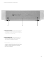
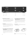
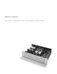
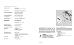
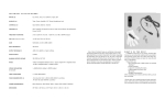
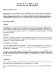
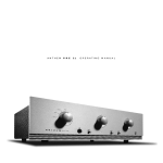
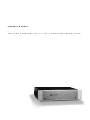
OWNER’ S MANUAL
T HE SO N IC F R ONT I ER S S FP -1 & S FP - 1 SIG N A TUR E PH O N O S T A G E
CONTROL FUNCTIONS AND CONNECTIONS
A
B
C
A-Mute/Operate Switch - In the mute position, this toggle switch
cuts off the signal to the outputs (F) of the SFP--1 hence muting the unit;
the LED (B) flashes as a reminder. In the operate mode, the outputs are
connected and the SFP-1 operates normally.
B-Power Indicator LED - This LED lights when the SFP-1 is on
and receiving power from the AC source. It will flash at one
second intervals during warmup delay and muting.
C-Power Switch - This toggle switch, when in the ON position, allows the SFP-1 to receive power, rendering the SFP-1
operational as indicated by the Power Indicator LED (B). When
the switch is in the OFF position the SFP-1 is not receiving
power and is not operational.
2
D
E
D-Detachable Power Cord Socket - Plug the Detachable
Power Cord into this socket (see Figure 1). The SFP-1 is factory
set for the correct operating voltage for the area in which it is
sold (see shipping box for voltage setting). If a different operating voltage is required, please contact an authorized Sonic
Frontiers dealer, distributor or the factory directly.
E- AC Line Fuse - This is the AC fuse socket. It may be
accessed with a small slot screwdriver by turning a 1/2 turn
counterclockwise to unlock a spring that ejects the fuse holder
out. The unit is factory installed with a “fast-blo” 1.5 Amp
250V (0.25” x 1.25”) or 0.75 Amp 250V (0.25” x 1.25”)
for European and Asian versions.
F
G
H
G- Left and Right Channel RCA Single-Ended Phono
Stage Input Connectors - These inputs accept a singleended input connection from a turntable’s output connectors.
The turntable equipped with a Moving Coil or Moving Magnet
Cartridge (see operation section for proper setup) connects
to the SFP-1. Left channel output to the left channel input of
the SFP-1 and right channel output to the right channel input
of the SFP-1.
H-Ground Post - All turntable ground wires should be connected to the SFP-1 ground post to prevent any “hum” from interfering with the music signal.
F- Left and Right Channel RCA Single-Ended Audio
Output Connectors - The SFP-1’s RCA single-ended
audio outputs are to be connected to the RCA single-ended
audio inputs of a line level preamplifier, control amplifier,
integrated amplifier or receiver. Left channel output of the
SFP-1connects to the left channel input of control unit and
right channel output of the SFP-1 to the right channel input
of control unit.
3
Figure 1 - Align socket pins to corresponding holes and push together firmly.
3
INSERTION OF THE TUBES AND
GAIN SETTING
The SFP-1 comes with two Sovtek 6922 (6DJ8-type) and two 12AT7A
tubes (the SFP-1 Signature comes with two Mullard 6DJ8/6922 and
two Gold Aero12AT7A Gold Grade), individually boxed, marked
and bagged along with a cotton glove, screwdriver, and screws for
fastening the SFP-1 cover. The following tube types will work under the
same technical parameters as the 6922 and require no circuitry modification to function:
• 7308/E188CC • 6DJ8/ECC88 • E88CC •12AT7A/ECC81
Please read and follow these instructions carefully for initial tube insertion or tube replacement. Great care was taken in the testing, selection
and matching of the supplied tubes in order to ensure proper operation of the unit. Casual replacement of tubes is NOT recommended.
1. Be sure that the AC DETACHABLE POWER CORD IS DISCONNECTED from the SFP-1 for 5 minutes prior to removing the chassis
cover in order to allow internal voltages to drain.
2. Using the Phillips screwdriver, remove the cover of the SFP-1. For
convenience, only two of the screws are fastened.
3. When handling the tubes, it is recommended that the cotton gloves
provided be worn to prevent skin oils from depositing on the glass surface and possibly causing the tube to become prematurely “gassy”,
thereby shortening the tube’s useful operating life.
4. Inspect the tubes for code markings. They will be coded individually,
each with one of the following codes: LV1, LV2, V1 and V2.
5. Inspect the tube sockets in the SFP-1 Phono Stage for the codes
matching the codes on the tubes. The coding is printed on the PCB circuit board beside the tube sockets. See Figure 2 for further clarification.
6. Take the tube marked LV1 and inspect the pins, noting the larger
space between two of the pins. This space will align with the same
larger space between two of the pin holes on the socket. Insert the LV1
tube into the LV1 tube socket, making sure all pins and pin holes are
aligned (see Figure 3). Do not force the tube into the socket. “Rock” the
tube gently while pushing slowly until the tube is firmly seated.
Figure 2 - Overview of the SFP-1
Phono Stage showing tube placement,
MM/MC slide switches, R-Load and
C-Load locations.
WARNING - DISCONNECT the AC
Detachable Power Cord from the SFP-1
and wait 5 minutes before removing the
chassis cover.
Repeat this step for the remaining tubes; LV2 tube to the LV2 tube socket, V1 tube to the V1 tube socket and V2 tube to the V2 tube socket.
7. Two slide switches for gain setting left and right channel are located beside the LV1 and V2 tube sockets. These switches are to be
moved inward to the MM position if a Moving Magnet or high output cartridge of 1.0mv or greater is in use. If a Moving Coil or low to
medium output cartridge of 0.2mv to 1.0mv is used, slide the switches outward to the MC position (see Figure 2).
NOTE: If insufficient gain is realized from the SFP-1 with a high output
cartridge when in the Moving Magnet mode, an extra 20 dB of gain
may be utilized by the Moving Coil mode. The SFP-1 has sufficient
overload reserve to handle high signal input levels if this mode is
chosen.
Also refer to the Operation section of this manual for turntable set up
if a Moving Coil mode is chosen.
8. Replace the cover and fasten it with the screws provided. The SFP-1
Phono Stage is now ready for operation.
Note the larger space
between two of the pins and
holes for proper alignment
of tube and socket.
Figure 3 - Tube pin alignment with the socket.
WARNING - DISCONNECT the AC Detachable Power Cord from
the SFP-1 and wait 5 minutes before removing the chassis cover.
4
OPERATION OF THE SFP-1 PHONO STAGE
TROUBLESHOOTING
Before plugging in the SFP-1, check to see that the unit is configured
for the correct AC line voltage for country of use. The operating AC
line voltage is indicated on the side of the shipping box. If the SFP-1
Phono Stage is set incorrectly for the country in which it is to be operated, contact the dealer or distributor in your area. If the unit is configured properly continue with operation.
If at any time the SFP-1 Phono Stage fails to work properly, consult
this checklist:
1. Check that the AC Detachable Power Cord is plugged into the
SFP-1 Detachable Power Cord Socket (F) and is connected to a live
source of AC power. For instance, if using a power bar, check that
the bar is turned on.
2. Ensure that the turntable is properly connected to the SFP-1 Inputs
(G) and that the SFP-1 Outputs (F) are properly connected to the line
level inputs of the system’s preamplifier, control amplifier, integrated amplifier or receiver. A secure contact must be made.
3. DISCONNECT THE AC POWER CORD from the SFP-1; check that:
• A “fast-blo” fuse, with a rating of 1.5 Amp/250 V (.075 Amp/
250 V for European and Asian versions), is installed in the AC power
socket (E).
• The AC power fuse is intact and has not blown. If the fuse has
blown the thin metal conductor will have melted and the glass may
appear “smoked”. If the fuse has blown, replace with a fuse of the
same rating (1.5 Amp/250V fast-blo for 100 to 120 volt countries
and 0.75 Amps/250V fast-blo for 200 to 240 volt countries).
NOTE: Under no circumstances should you replace the AC power fuse
with one of a higher current rating! Doing so may cause further damage
to the SFP-1 and will also void the warranty. In addition, your continued
protection from risk of fire or shock would be seriously compromised.
4. DISCONNECT THE AC POWER CORD, remove cover and ensure
the tubes are plugged firmly into their sockets as described in “INSERTION OF THE TUBES”.
5. Be sure the rest of the system is functioning properly (i.e. turntable,
power amplifiers, cables and connections, etc.).
6. Review Operation section of this manual. Check that the front panel
Power Indicator LED (D) is lighted (glowing light green). If all of the
above troubleshooting steps have been followed and the light is not
lighted (dark green), contact your dealer or distributor for assistance.
Connect the detachable power cord to the SFP-1 chassis (see Figure
1) and plug your SFP-1 into the AC power source.
If the Moving Coil Mode is chosen for use, the SFP-1 Phono Stage
inverts the signal’s output polarity, putting the signal out of phase. To
correct this and bring the signal back to absolute phase, switch the
“+” and “–” leads at your cartridge pins. This is important for correct
operation of the phono playback system. Typically, the red and green
leads are reversed (right channel) and the blue and white (left
channel) are also reversed.
Connect the turntable’s left and right RCA outputs to the corresponding
left and right RCA Inputs (G) on the SFP-1 using a suitable length of
interconnect. Also connect the ground lead from the turntable to the
Ground Post (H) on the SFP-1 (see Figure 4).
Using your favorite interconnect, connect the left and right channel
RCA (Single-Ended) Outputs (F) of the SFP-1to the corresponding left
and right channel line level audio inputs of the system’s preamplifier,
control amplifier, integrated amplifier or receiver (see Figure 4). We
recommend no more than 3’ (1m) of interconnect for best results.
The SFP-1 Phono Stage is now ready for operation. Power the unit by
placing the Power Switch (E) in the ON position (ensure the
Mute/Operate Switch (A) is in the Operate position). As soon as the
SFP-1 is plugged in and turned ON, the front panel Power Indicator
LED (D) will flash on and off for approximately 45 seconds. During this
time, the signal outputs are muted while the tubes are warming up and
stabilizing. As soon as the Power Indicator LED (D) stops flashing and
lights green, the SFP-1 is ready for use. Cue the LP you wish to play,
and enjoy your new SFP-1.
CARTRIDGE LOADING OPTIONS - RESISTANCE
In either “MM” or “MC” cartridge operating modes, the input load
resistance that the cartridge sees is factory set at 49K9 (or 49.9K) ohms.
This may be easily altered by your dealer (or a competent technician)
by soldering a new resistance value to the solder terminals labeled “RLoad” (one per channel). For your convenience, your SFP-1 comes
packed with 4 different commonly used resistor values (1K, 100R,
30R and 10R) to allow you to adjust the nominal 49K9 load to the following values: a) 980 ohms (using the 1K resistors); b) 100 ohms
(using the 100R resistors); c) 30 ohms (using the 30R resistors); and
d) 10 ohms (using the 10R resistors). See Figure 3 for load resistor location.
CARTRIDGE LOADING OPTIONS - CAPACITANCE
Figure 4 - Connections to the RCA Outputs and Inputs of the
SFP-1 Phono Stage.
With some phono cartridges (both moving magnet and moving coil),
the addition of some capacitance loading to the cartridge may prove
beneficial in “taming” any high frequency resonance or response
peaks inherent in the design of the cartridge. Typical capacitance values for moving magnet cartridges are in the range of 100 to 250pf.
We suggest that you discuss the possible loading requirements of your
cartridge with your dealer, or with the cartridge manufacturer. The
additional capacitance may be soldered to the “C-Load” solder terminals (of both channels). Loading capacitors can be obtained from
The Parts Connection, a division of Sonic Frontiers. See Figure 3 for
load capacitor location.
5
SFP-1 PLACEMENT FOR PROPER VENTILATION
LIMITED FIVE YEAR WARRANTY
Allow at least 6” (15 cm) of clear space above the SFP-1 chassis for proper ventilation, making sure the air vent slots in the
chassis cover remain unobstructed.
Sonic Frontiers, Inc. warrants to the purchaser that each SFP-1
Phono Stage is free of manufacturing defects for a period of
five (5) years from the date of purchase. This five (5) year limited non-transferable warranty excludes all vacuum tubes, which
we warrant for a period of twelve (12) months. To receive this
warranty, the original purchaser must complete and mail to
Sonic Frontiers, within thirty (30) days from the date of purchase, the enclosed Warranty Registration Card. Sonic
Frontiers, Inc. will then validate the warranty to the original purchaser. This warranty is subject to the following conditions and
limitations:
SAFETY INSTRUCTIONS
1. Ventilation - Although your SFP-1 Phono Stage generates only
nominal heat in use, be sure that the ventilation slots in the top
cover have at least 6” of unobstructed air space above them.
2. Water and Moisture - This product should not be used near
water. To prevent fire or shock hazard, do not expose this
product to rain or moisture.
3. Heat - This product should be situated away from heat
sources such as radiators, heat registers, stoves, or other appliances which produce heat.
4. Power Sources - This product should be connected to an AC
power source of the proper rated voltage. The original shipping containers will stipulate the AC voltage this unit can operate with correctly.
5. Cleaning - A regular dusting with a soft, non-abrasive cloth
will generally keep the finish of the faceplate and chassis looking like new. At no time should you allow any liquid to come in
contact with the SFP-1 Phono Stage; it may run into the electronic circuitry and cause damage which will not be covered
under your warranty.
6. Servicing - Refer servicing to an authorized service technician.
7. Non-Use Periods - The power cord of this product should be
unplugged from the outlet when left unused for an extended
period of time.
8. Do not remove the SFP-1 chassis cover while the unit is
“on”, or connected to an AC power source. Cover screws
could fall through the ventilation slots and cause electrical
damage to the SFP-1.
PACKING MATERIALS
We recommend that you retain all of the packing material and
shipping boxes for your SFP-1 Phono Stage. They are custom
designed to prevent shipping damage from occurring. Sonic
Frontiers, Inc. will accept no responsibility for any damage
occurring to an SFP-1 Phono Stage that is shipped in packing
material other than the original Sonic Frontiers packing material.
DISCLAIMER OF LIABILITY
Under no circumstances does Sonic Frontiers, Inc. assume liability or responsibility for injury or damages sustained in the use
or operation of this equipment or for damages to any other
equipment connected to it.
Sonic Frontiers, Inc. reserves the right to make design changes
or improvements without the obligation to revise prior versions.
All specifications are subject to change without notice.
1. Warranty applies only to the original purchaser from an
authorized Sonic Frontiers reseller.
2. This warranty is void and inapplicable if the product has
been handled other than in accordance with the instructions in
this Owner’s Manual, abused or misused, damaged by accident or neglect or in being transported, or the defect is due to
the product being tampered with, modified or repaired by anyone other than Sonic Frontiers, Inc. or an authorized Sonic
Frontiers repair depot.
3. Warranty does not cover normal maintenance.
4. Sonic Frontiers, Inc. shall not be responsible in any way for
consequential or indirect damages or liabilities resulting from
the use and operation of the product covered herein or resulting from any breach of this warranty or any implied warranty
relating to said product.
During this period, Sonic Frontiers, Inc. will repair or replace
any defective components free of charge. A Return Authorization Number (RA Number) is required before any product is
returned to our factory for any reason. This number must be visible on the exterior of the shipping container(s) for Sonic
Frontiers to accept the return.
Units shipped to us without a Return Authorization Number or
without a visible RA Number on the exterior of the shipping
container(s) will be returned to the sender, freight collect.
Units to be repaired by Sonic Frontiers, Inc. must be sent shipping and insurance prepaid by the original purchaser in the
original packing material. A returned product should be accompanied by a written description of the defect. Repaired units
will be returned by Sonic Frontiers, Inc. shipping and insurance
prepaid.
All other warranties or conditions either written or implied
are void.
Note: In foreign markets (anywhere outside of Canada and the
USA), the warranty is supplied by the authorized International
Distributor. Exact terms and conditions may vary.
6
SFP-1 & SFP-1 SIGNATURE TECHNICAL SPECIFICATIONS
Frequency Response 20 Hz to 20 kHz ± 0.3 dB (RIAA accuracy)
THD & Noise
< 0.05% @ 1.0V output
Gain
(selected internally)
37 dB Moving Magnet
57 dB Moving Coil
Output Impedance
1K ohms @ 1 kHz
Input Impedance
47K ohms (adjusted internally)
Channel Separation > 40 dB (20 Hz to 20 kHz)
Power Requirements 35 VA 50/60 Hz (maximum)
Tube Complement
Signature Version
2 - Sovtek 6922
2 - 12AT7A
2 - Mullard 6DJ8/6922
2 - Gold Aero 12AT7A Gold Grade
Dimensions
19” Wide x 11” Deep x 4” High
(48 cm x 28 cm x 10 cm)
Weight
22 lbs (10 kg) - unpacked
Warranty
5 years parts and labor
1 year on the tubes
This symbol is intended to alert the
user to the presence of uninsulated
“dangerous voltage” within the
product’s enclosure that may be of
sufficient magnitude to constitute
a risk of electric shock to persons.
This symbol is intended to alert the
user to the presence of important
operating and maintenance (servicing)
instructions in the literature accompanying the appliance.
SKU# 56550 6/96
7
We at Sonic Frontiers are sure that you will derive many years
of listening pleasure with your new SFP-1 or SFP-1 Signature
Phono Stage. This Owner’s Manual contains important information regarding the operation and care of the SFP-1. Be sure to
read this manual carefully and follow these instructions in order
to keep it looking, operating and sounding its best.
2790 Brighton Road, Oakville, Ontario, Canada L6H 5T4
Telephone: (905) 829-3838 Facsimile: (905) 829-3033
Sonic Frontiers can be reached from 9:00 a.m. to 6:00 p.m., Eastern Standard Time (E.S.T.), or 24 hours a day by facsimile.