1
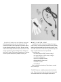
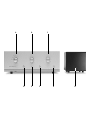
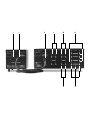
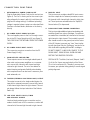
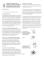
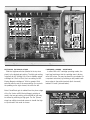
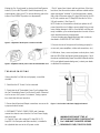
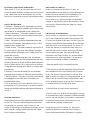
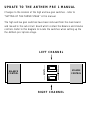
D E S I G N E D
A N D
M A N U F A C T U R E D
B Y
279 0 BR IG HTO N R OA D, O AK VIL LE , ONTA RIO , C A NA DA
S o n i c
F r on t i e r s
c a n
b e
r e a ch e d
9 : 0 0
a m
t o
S O N I C
L 6H 5T4
6 :0 0
p m
F R O N T I E R S
I N C O R P O R A T E D
T EL: (9 0 5) 82 9 -383 8
( E . S . T. )
o r
2 4
h ou r s
FA X: (90 5) 8 29- 303 3
a
d a y
b y
f a cs i mi l e .
ANTHEM PRE 1
OPERAT ING M A NU AL
TECHNICAL
SPECIFICATIONS
(AC line set at 117V 60Hz)
FREQ UEN CY RE SPONSE: Line input: ± 0.5dB 10Hz to
85kHz, -3dB below 5Hz and above 200kHz
Phono Input: ± 0.5dB of RIAA 20Hz to 20kHz
CHANNE L SEPA R AT I O N : (Line Stage): < -75 dB Below 1V
@ 1kHz, < -65dB Below 1V @ 20kHz, (Phono Input to Line
Stage Output): < -55dB @ 1kHz, < -55dB Below 1V 10Hz to
20kHz
P H A S E : Phono to Tape outputs: Non-inverting, Line in to
Main output: Inverting
HARMONIC DISTO RTION: (THD+N): Less than 0.1% at 2V
RMS (Line input to Main output), 10Hz to 60kHz; Less than
0.35% at 1V RMS at main output (Phono input to line output), 20Hz to 20kHz (typically less than 0.15% at midband,
phono input)
N O I S E : (Unweighted, shorted input): Line Stage: -95dB
TUBE C OMPLEMENT: Tube Audio Circuit: 4-Sovtek
I N T E R M O D U L ATION DI ST OR TION (SMPT E) : Line input to
6922/6DJ8, 2-12AT7/ECC81, Tube Rectifier In Power
Supply: 1-5AR4/GZ34
below 1V Output 10Hz to 20kHz, Phono In to Line Stage
Output: -75 dB below 1V Output 20Hz to 20kHz
Main output < 0.1% at 1V RMS, Phono input to Main output
POWER REQUIR EMENTS: 100-130VAC 60Hz
G A I N : at 1kHz (Internally Selectable) Phono input to tape
(Export 200-240VAC 50/60Hz) 70 VA maximum
output: 48dB, Phono input to main output: 61dB or 78dB
(switchable), High level input to main output: 29dB
D I M E N S I O N S : Pre 1 Chassis: 19" (48 cm) W x 5 1/4" (13.4
INPUTS ( 5): CD, Tuner, Aux, Phono, Tape
O UTPUTS (3) : Tape, Main 1, Main 2,
CONTROLS ( 3): Input Select, Balance, Volume
S WITCHES (3): Tape/EPL (External Processor Loop),
Mute/Operate, On/Off
INPUT IMPED ANC E: Phono: 47K, Phono Input
Capacitance: 100pF (provision on PCB for addition of additional phono loading components) High Level: 50K ohms
or higher depending on balance control setting.
O UT PUT IMPEDANCE: 390 ohms main outputs, Phono
520 ohms to tape outputs, Recommended load 50K-100K
ohms and 100pF (20K ohms minimum, 1000pF maximum)
R ATED O UTPUT : 1V RMS 10Hz to 85kHz main outputs
(Maximum 44V RMS output at 0.5% THD at 1kHz into 100K
ohm load with 1.7V RMS high level input)
cm) H x 11” (28 cm) D, Knobs extend 3/4" (1.9 cm) forward of panel. Detachable Interconnect cable extends 4"
behind rear of chassis. Detachable Power Supply: 7 1/8”
(18.4 cm) W x 5 1/8" (13.4 cm) H x 9” (22.9 cm) D
W E I G H T: Pre 1 Chassis: Net 17.5 Ibs, (7.9 kg); Power
Supply: Net 10 Ibs. (4.54 kg); Shipping 30 Ibs (13.6 kg)
We at Sonic Frontiers hope you will derive many years
of listening pleasure with your new Anthem Pre 1. This
Operating Manual contains important information regarding the operation and care of the Pre 1. Be sure to read
this manual carefully and follow these instructions in order
to keep it performing and sounding its best. Please contact Sonic Frontiers if you have any questions, a Customer
Service Representative will be pleased to assist you.
W H AT ’ S I N T H E B O X ?
In addition to the Pre 1, the Power Supply (their appropriate covers), and the operating manual you are presently
reading (with associated inserts and warranty card), there
are a few more items to take inventory of before steps are
taken to make the Anthem Pre 1 operational.
These items are:
• one matched pair of 12AT7 tubes, totaling 2
• two matched pairs of 6922 tubes, totaling 4*
• one 5AR4 rectifying tube
• a glove for handling the tubes
• a detachable AC power cord
• a handful of screws
• a screwdriver
After completing an inventory of these items, proceed
to the next steps.
*The 6922 tubes are carefully measured and matched in
pairs. Take extra care to keep the pairs from being mixed
and mismatched which would degrade performance.
A
B
D
E
C
F
G
H
CONTROL
A
FUNCTIONS
SELECTOR S WIT CH
E
This knob is rotated to select a Line Level Input (N) or
the Phono Input (P). The Selector Switch is bypassed
when the Tape/EPL(External Processor Loop) mode is
selected by depressing the Tape/EPL-Source button (D).
B
This Light Emitting Diode has three status conditions
identified by different displays. They are:
• DIM (Sleep)- indicates the Power Supply is plugged
in and connected to the Pre 1; the On-Off (G) is in
the OFF position (not depressed) and tube filaments
are turned on. When the Pre 1 is put in the ON
mode, the light will remain DIM for 45 seconds during a start-up/mute cycle.
• ON (Normal Intensity)- indicates the On-Off button
(G) is depressed in the ON position and the Pre 1 will
allow normal funtion.
• FLASH (Normal Intensity)- indicates the Pre 1 is
muted; the Mute-Operate button (F) is depressed in
the Mute position.
BALANCE C ONTR OL
This knob controls the relative balance of the left and
right channels to compensate for any discrepancies
caused by speaker placement, source imbalance, etc.
Full rotation to the left or right of the center detent will
have a ±6dB trim on levels between left and right
channels.
C
VOLUME CONT RO L
This knob allows variable control over the Pre 1 output
level. Turn it clockwise and the music gets louder!
D
F
M U T E - O P E R ATE BUTTON
When in the OPERATE position (not depressed), this
button will allow normal function. When in the MUTE
position (button depressed), the music signal is cut off
from reaching the Outputs (L). The LED (E) will flash as
a reminder.
TAPE /EPL (EXTERNAL PR OCE SS OR LOOP)SO URC E BUTT ON
When this button is in the SOURCE position (button is
not depressed) the signal is routed through the
Selector Switch (A) to the Tape/EPL Output (M) connected with a tape deck or external processor such as
a surround sound decoder. Listening and taping is
done in this mode. When the button is depressed the
source signal is taken from a tape or processor source
through the Tape/EPL Inputs (O) bypassing the selec tor switch.
PREAMPLIFIE R LED
G
ON- OFF BUTT ON
When in the ON position (button depressed), high voltage power is received by the Pre 1 circuitry from the
Power Supply. A delay of approximately 45 seconds is
required for turn-on due to the soft-start nature of the
rectifying tube in the Power Supply. When in the OFF
position (not depressed), the Pre 1 is in standby mode;
power is received by the tube filaments only.
H
POW ER SUPPLY LED
This LED will light at normal intensity to indicate the
power supply is plugged in and the tube filaments are
receiving low voltage power. For regular use, it is safe
to leave the Power Supply plugged in and receiving
power. If the unit is to sit idle for one week or more,
the operator may wish to unplug the AC power cord.
I
J
K
L
M
N
O
P
CONNECTION
I
FUNCTIONS
D E TACHABLE AC PO WER CO RD SOCKET
Plug the Detachable Power Cord into this socket (see
Figure 4). The Pre 1 is factory set for the correct operating voltage for the area in which it is sold (see shipping box for voltage setting). If a different operating
voltage is required, please contact an authorized Sonic
Frontiers or Anthem dealer, distributor or the factory
directly.
J
DC POWER SU PPLY UMBI LIC AL C ORD
This cord supplies power to the Pre 1 through connection to the DC Power Supply Input (K) (see Figure 3).
THIS CORD IS NOT DETACHABLE FROM THE POWER
SUPPLY.
K
DC POWER SUPPLY INPUT SOC KET
This connector accepts a connection from the DC
Power Supply Cord (J).
L
TAPE/EPL (EXTERNAL PR OC ESS OR LOOP) OUTPUT
This output connects to the single-ended inputs of a
tape deck or external processor; connect left channel
to left channel right channel to right channel. This output always follows the input selection of the Selector
Switch (A).
N
TAPE /EPL INPU T
This input accepts a single-ended RCA input connection from a tape deck or external processor;connect
left channel to left channel right channel to right channel. These inputs are activated when the Tape/EPLSource button (D) is depressed.
P
PHON O INPUT AND G RO UND CONNECTION
This input provides additional gain when dealing with
sensitive signals from phono cartridges. Connections
are made from a turntable; left channel to left channel
right channel to right channel. The turntable’s ground
wire should connect to the ground post at the centre
of the RCA inputs to prevent any “hum” from interfering with the signal. See the “Setting up” section for further clarification regarding MM and MC cartridges.
DO NOT CONNECT A LINE LEVEL SOURCE TO THE
PHONO INPUT. DOING SO WILL OVERLOAD AND
DESTROY THE SENSITIVE CIRCUITRY.
MAIN O UTPU TS ONE AND TW O
These outputs connect to the single-ended inputs of
other units such as power amplifiers or a crossover
unit; connect left channel to left channel and right
channel to right channel. The set of two allows for
easier biamping and greater flexibility when dealing
with components such as electronic crossovers, powered subwoofer, etc.
M
O
LINE L EVEL INPUTS F OR CD , T UNER
AND AUXILIARY SOURCE
Line level single-ended source connection may be
made to these 3 sets of RCA connectors; connect left
channel to left channel right channel to right channel.
SPECIAL NOTE: The Main (Line Level) Outputs 1 and 2
(L) of the Pre 1 are a reversed polarity of the Phono
(P) or Line Level Inputs (N). Therefore, you may want
to reverse your speaker wiring polarity to ensure signal
polarity alignment.
WARNING- DISCONNECT THE AC
DETACHABLE POWER CORD FROM THE
PRE 1 AND WAIT 5 MINUTES BEFORE
REMOVING COVER, TUBES OR FUSE.
SETTING
UP
The Pre 1 comes with seven tubes, as follows:
5AR4 R ECTIFIER TUBE
The tube socket for this tube is located in the power supply.
This tube functions as a full wave rectifier, converting the AC
supply to DC. A tube was chosen for this function because
a semiconductor tends to sound harsh in this application.
As well, when switching to high voltage, the tube has a slow
turn-on, providing a gradual “soft” start which is easier on
the circuitry and the other tubes. This tube may be replaced
with the 5Y3 rectifier tube; but note a difference in performance may be heard, the 5AR4 performs better than the
5Y3 when the operating voltage is low.
6922 (LV1 & V1) FIRST INPUT STAGE TUBES
These Russian Sovtek tubes were chosen for their reliability and extremely low noise performance. When dealing
with the low voltage, sensitive signals of phono cartridges,
this is imperative that a tube is quiet. The 6922 tubes may
be replaced with a matched set of ECC88/6DJ8s or
E188CC/7308s with no circuit modification.
1 2 AT 7 (LV2 & V2) SEC ON D INPUT STAGE TUBE S
These tubes provide the drive as the output stage of the
phono section. The signal levels are padded by the
High/Low gain slide switches preceding the linestage
(typically set to “high” for MC-moving coil and “low” for
MM-moving magnet). The 12AT7 tubes may be replaced
with a matched set of ECC81s or 6201s with no circuit
modification.
6 92 2 (LV3 & V3 ) LINE STAGE TUBES
These tubes were again chosen for their reliability and
extremely low noise. This single tube configuration delivers
good drive and output current to the power amplifier. The
tubes’ quietness heightens dynamics and they are tonally
natural. The 6922 tubes may be replaced with a matched
set of 6DJ8s with no circuit modification.
INSER TION OF THE TUBE S
1. Using the screwdriver supplied, remove the cover of
the Pre 1. For your convenience, only two of the screws
are installed at the factory.
2. When handling the tubes, it is recommended that the
cotton gloves provided be worn to prevent skin oils from
depositing on the glass surface and possibly causing the
tube to become prematurely “gassy”, thereby shortening
the tube’s useful operating life.
3. Noting the location of the tube sockets in the top view
photo/or directly on the PC Board, inspect the tubes for
corresponding labels and markings. Once locations are
mapped, take a tube and inspect the pins, noting the
larger space between two of the pins or the key peg on
the 5AR4 (see Figures 1 & 2). This space or key will
match with the socket. Insert each tube into the appropriate tube socket, making sure all pins and pin holes are
aligned. Do not force the tubes into the sockets. “Rock”
the tubes gently while pushing slowly until each tube is
firmly seated.
Note the larger space
between two of the pins and
holes for proper alignment
of tube and socket.
Figure 1
Note the key on the centre
peg and hole for proper
alignment of tube and socket.
Figure 2
FUSE
FUSE
LOCATION
LOCATION
LV1
LV1 &
& V1
V1
6922s
6922s
LV2
LV2 &
& V2
V2
12AT7s
12AT7s
LV3
LV3 &
& V3
V3
6922s
6922s
5AR4
5AR4
Hi/Lo
Hi/Lo gain
gain
switching
switching
SETT ING UP THE P HONO STA G E
CARTR IDGE LOADING - RE SIS TA N C E
Slide the high/low switches (labeled in the top view
photo) to the desired gain setting. The High gain setting
is typically for MC-Moving Coil or low to medium output
cartridges of 0.2mV to 1.0mV; the Low setting for MMMoving Magnet cartridges of 1.0mV or greater. Both
switches must be set to the same setting. One controls
the padding on the right channel, the other the left.
In either MM or MC cartridge operating modes, the
input load resistance that the cartridge sees is factory
set at 47K ohms. This may be altered by your dealer (or
competent technician) by soldering a new parallel resistance value to the solder terminals (both channels)
labeled “R-Load” (pictured below).
Note: If insufficient gain is realized from the phono stage
of the Pre 1 when a MM-Moving Magnet cartridge is
used in the low gain setting, an extra 18dB of gain may
be utilized by switching to High gain. The Pre 1 phono
stage has sufficient overload reserve to handle the higher input levels if this mode is chosen.
Phono Cartridge Loading
Resistance and Capacitance
solder
solder terminals
terminals
CARTR IDG E L OADING - CAPA C I TA N C E
With some phono cartridges (both MM and MC), the
addition of some capacitance loading to the cartridge
may prove beneficial in “taming” any high frequency resonance or response peaks inherent in the design of the
cartridges. Typical capacitance values for MM cartridges
are in the range of 100 to 250pf. We suggest that you
discuss the possible loading requirements of your cartridge with the dealer where you purchased the cartridge
or with the cartridge manufacturer. The additional capacitance may be soldered to the “C-Load” solder terminals
(both channels).
After the insertion of the tubes and the phono stage setup, replace the cover and fasten it with the screws provided. The Pre 1 is now ready for operation. For further information on tube replacement, NOS (New Old Stock) tubes,
loading, resistance or capacitance parts contact a Sonic
Frontiers Customer Service Representative or The Parts
Connection, a division of Sonic Frontiers.
OPERATION
Before plugging in the Pre 1, check to see that the unit is
configured for the correct AC line voltage for country of
use. The operating AC line voltage is indicated on the side
of the shipping box. If the Pre 1 is set incorrectly for the
country in which it is to be operated, contact the dealer or
distributor in your area. If the unit is configured properly,
continue with operation.
Connect the DC Power Supply Cord (J) to the Pre 1 DC
Input (K) (see Figure 3) before connecting the Detachable
Power Cord to the Pre 1 Power Supply chassis (I) (see
Figure 4). Plug your Pre 1 into the AC power source.
Note: Never operate the Pre 1 Power Supply when not
connected to the DC input on the main chassis.
All remaining connections are made with co-axial cable
and RCA connectors to or from other single-ended units.
Connect source units to the Inputs of the Pre 1 (N and P);
left channel to left channel and right channel to right channel.
If a tape or other line level recording or processing device
is being implemented, connect the left and right audio output of the unit to the corresponding left and right Tape/
EPL Input (O) of the Pre 1. Also connect the left and right
Tape/EPL Outputs (M) on the Pre 1 to the corresponding
left and right audio inputs of the external device.
Connect Set 1 of the Main Outputs (L) on the Pre 1 to a
stereo amplifier or two mono amplifiers; left channel to left
channel and right channel to right channel. Set 2 of the
Main Outputs (L) may be used under different situations
and in combination with Set 1. These situations include
biamping, the use of active crossovers, powered subwoofers and other equipment; all situations being unique
and system dependent. Refer to the instruction manuals
provided with the other equipment before using the second set of Outputs.
The Pre 1 is now ready for operation. Power the Pre 1 by
placing the On-Off button (G) in the ON position. The
Power Indicator LED (E) will stay DIM for approximately 45
seconds. During this time, the signal outputs are muted
while the tubes are warming up and stabilizing. As soon as
the Power Indicator LED is at steady, normal intensity, the
Pre 1 is ready to play.
Select a ready source through the Selector Switch (A).
Balance is adjusted through use of the Balance Control (B);
turning it left and right will adjust the left and right levels
respectively in a -6dB adjustment range. The center detent
is an indicator for equal, or balanced, left and right levels.
Volume is adjusted through use of the Volume Control (C).
Turning this control clockwise increases the volume level
of both channels. Be sure the level is sufficiently low when
turning the unit ON or returning to the OPERATE mode
after MUTING, to prevent damage to speakers, amplifiers
or the Pre 1 itself.
To record from a source, place the Tape/EPL-Source button (D) in the SOURCE position, select the source material
you wish to record via the Selector Switch (A), and commence recording. To play back a tape recording, place the
Tape EPL/ Source button in the TAPE position.
Muting the Pre 1 is achieved by placing the Mute/Operate
button (G) in the MUTE position (button depressed); the
output signal is then cut off. To resume listening, place the
button in the OPERATE position (not depressed).
• The AC power fuse is intact and has not blown. If the fuse
has blown, the thin metal conductor will have melted and the
glass may appear “smoked”. If the fuse has blown, replace
with a fuse of the same rating (1.5 Amp/250V fast-blo for 100
to 120 volt countries and .75 Amp/250V fast-blo for 200 to
240 volt countries). (See Figure 5.)
NOTE: Under no circumstances should you replace the AC
power fuse with one of a higher current rating! Doing so may
cause further damage to the Pre 1 and will also void the warranty. In addition, your continued protection from risk of fire or
shock would be seriously compromised.
• Ensure the tubes are plugged firmly into their sockets as
described in “INSERTION OF THE TUBES”.
Figure 3 - Alignment of the DC power connector and cable.
5. Be sure the rest of the system is functioning properly (i.e.
source unit, power amplifiers, cables and connections, etc.).
Figure 4 - Alignment of the AC power connector and detachable cord.
6. With tubes, fuses, covers and power cords in place, check
that the LEDs (E&H) are lighted (glowing light green). If all of
the above troubleshooting steps have been followed and the
LED is not lighted (remains dark green), contact your dealer
or distributor for assistance.
TROUBLESHOOTING
If at any time the Pre 1 fails to work properly, consult this
checklist:
1. Check that the DC Power Cord is connected.
2. Check that the AC Detachable Power Cord is plugged into
the Pre 1 Detachable Power Cord Socket (I) and is connected
to a live source of AC power. For instance, if using a power
bar, check that the bar is turned on.
3. Ensure that all Input and Output connections are secure for
a proper electrical contact.
4. DISCONNECT THE AC POWER CORD, wait 5 minutes,
remove the chassis covers from the Pre 1 and Power Supply
and check that:
• A “fast-blo” fuse, with a rating of 1.5 Amp/250 V (.75
Amp/250 V for European and Asian versions), is installed in
the cylindrical tube next to the AC power socket.
Figure 5 - Fuse location in the Power Supply and removal.
WARNING-DISCONNECT THE AC
DETACHABLE POWER CORD FROM THE
Pre 1 AND WAIT 5 MINUTES BEFORE
REMOVING COVER, TUBES OR FUSE.
PLACEMENT F OR PROPER VENTILAT I O N
DISCLAIMER OF LI ABILITY
Allow at least 4” (15 cm) of clear space above the Pre 1
chassis for proper ventilation, making sure the air vent slots
in the chassis cover remain unobstructed. Also, be sure
that the Pre 1 is placed on a secure, hard and level surface.
Under no circumstances does Sonic Frontiers, Inc.
assume liability or responsibility for injury or damages sustained in the use or operation of this equipment or for
damages to any other equipment connected to it.
Sonic Frontiers, Inc. reserves the right to make design
changes or improvements without the obligation to revise
prior versions. All specifications are subject to change
without notice.
SAF ET Y INS TRUCTIONS
1. Ventilation - Although your Pre 1 generates only nominal
heat in use, be sure that the ventilation slots in the top cover
have at least 4” of unobstructed air space above them.
2. Water and Moisture - This product should not be used
near water. To prevent fire or shock hazard, do not expose
this product to rain or moisture.
3. Heat - This product should be situated away from heat
sources such as radiators, heat registers, stoves, or other
appliances which produce heat.
4. Power Sources - This product should be connected to an
AC power source of the proper rated voltage. The original
shipping container will stipulate the AC voltage this unit can
operate with correctly.
5. Cleaning - A regular dusting with a soft, non-abrasive
cloth will generally keep the finish of the faceplate and chassis looking like new. At no time should you allow any liquid to
come in contact with the Pre 1; it may run into the electronic
circuitry and cause damage which will not be covered under
your warranty.
6. Servicing - Do not open this product. No user serviceable
parts inside. Refer servicing to an authorized service technician.
7. Non-Use Periods - The power cord of this product should
be unplugged from the outlet when left unused for an
extended period of time.
8. Do not remove the Pre 1 covers while the unit is “on”, or
connected to an AC power source. Cover screws could fall
through the ventilation slots and cause electrical damage to
the Pre 1.
PACKING MAT E R I A L S
Please retain all of the packing material and shipping boxes
for your Pre 1. They are custom designed to prevent shipping damage from occurring. Sonic Frontiers, Inc. will
accept no responsibility for any damage occurring to a Pre 1
that is shipped in packing material other than the original
Sonic Frontiers packing material.
LIMITED FIVE YEAR WA R R A N T Y
Sonic Frontiers, Inc. warrants to the purchaser that each
Pre 1 is free of manufacturing defects for a period of five
(5) years from the date of purchase. This five (5) year limited non-transferable warranty excludes all vacuum tubes,
which we warrant for a period of twelve (12) months. To
receive this warranty, the original purchaser must com plete and mail to Sonic Frontiers, within thirty (30) days
from the date of purchase, the enclosed Warranty
Registration Card. Sonic Frontiers, Inc. will then validate
the warranty to the original purchaser. This warranty is
subject to the following conditions and limitations:
1. Warranty applies only to the original purchaser.
2. This warranty is void and inapplicable if the product has
been handled other than in accordance with the instructions in this Owner’s Manual, abused or misused, damaged by accident or neglect or in being transported, or the
defect is due to the product being tampered with, modified or repaired by anyone other than Sonic Frontiers, Inc.
or an authorized Sonic Frontiers repair depot.
3. Warranty does not cover normal maintenance.
4. Sonic Frontiers, Inc. shall not be responsible in any way
for consequential or indirect damages or liabilities resulting
from the use and operation of the product covered herein
or resulting from any breach of this warranty or any
implied warranty relating to said product.
During this period, Sonic Frontiers, Inc. will repair or
replace any defective components free of charge. A
Return Authorization Number (RA Number) is required
before any product is returned to our factory for any reason. This number must be visible on the exterior of the
shipping container(s) for Sonic Frontiers to accept the
return.
Units shipped to us without a Return Authorization Number
or without a visible RA Number on the exterior of the shipping container(s) will be returned to the sender, freight
collect.
Units to be repaired by Sonic Frontiers, Inc. must be sent
shipping and insurance prepaid by the original purchaser
in the original packing material. A returned product should
be accompanied by a written description of the defect.
Repaired units will be returned by Sonic Frontiers, Inc.
shipping and insurance prepaid.
All other warranties or conditions either written or implied
are void.
Note: In foreign markets (anywhere outside of Canada and the
USA), the warranty is supplied by the authorized International
Distributor. Exact terms and conditions may vary.
This symbol is intended to alert the user to the
presence of uninsulated “dangerous voltage”
within the product’s enclosure that may be of
sufficient magnitude to constitute a risk of electric shock to persons.
This symbol is intended to alert the user to
the presence of important operating and
maintenance (servicing) instructions in the
literature accompanying the appliance.
U P D AT E T O T H E A N T H E M P R E 1 M AN U A L
Changes to the location of the high and low gain switches - refer to
“SETTING UP THE PHONO STAGE” in this manual.
The high and low gain switches have been removed from the main board
and moved to the sub circuit board which contain the Balance and Vo l u m e
controls. Refer to this diagram to locate the switches when setting up the
the Anthem pre 1 phono stage.
LEFT CHANNEL
VOLUME
CONTROL
BALANCE
CONTROL
RIGHT CHANNEL