1
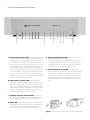
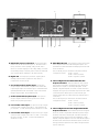
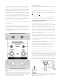
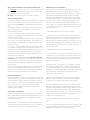
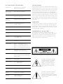
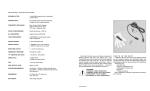
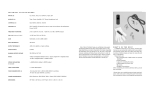
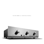
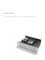
OWNER’ S MANUAL
T HE SO N IC F R ONT I ER S S FD - 2 MK I I DI GI TA L P R OCE S SO R
CONTROL FUNCTIONS AND CONNECTIONS
A
A-Phase Control Switch & LED - This switch allows the user
to invert the system phasing easily and safely. The switch is set
automatically to the 0° position where the SFD-2 MKII will put
out a normal or non-inverted signal in relation to the signal
being received from the source. Pushing the switch will put out
an inverted version of the signal as compared to that being
received from the source. The LED will light indicating that the
source signal phase is being inverted 180°. This feature offers
a convenient method of correcting source material which was
recorded “out of absolute phase” or to compensate for a component in your system, such as a preamplifier, power amplifier
or signal connection, which inverts phase.
B-Input Switch & Indicator LEDs - This switch selects
between the 5 digital inputs (I-M) located on the back of the
SFD-2 MKII: AES/EBU XLR, Coax RCA, Coax BNC, Optical
Toslink, Optical Standard (Glass Fibre). A connection to all 5
inputs may be made from 5 separate sources. To switch digital
sources, depress the button repeatedly to scan the inputs. The
LED will light corresponding to the input selection.
B
C
D
E
F
E- Signal Locking Indicator LED - This LED will light when
an operational digital source is selected.
NOTE: Depending on the source or transport being used in
conjunction with the SFD-2 MKII, it may be necessary to have
the source unit in the “PLAY” mode and the SFD-2 MKII receiving the digital transmission before the LED will light.
F- Operate Switch & Power LED - This switch, when
pressed, allows the SFD-2 MKII to receive full power, rendering
the SFD-2 MKII operational as indicated by the Power Indicator
LED. When the switch is off, the Power LED will not be lighted
and the SFD-2 MKII is not receiving full power; under these
conditions the SFD-2 MKII is not operational, but is in standby
mode.
C-Sampling Frequency Indicator LEDs - One of these
LEDs will light, indicating the frequency of the digital input signal. The sampling frequencies are 32K, 44K and 48K.
D-HDCD® LED - This will light when an HDCD (High Definition
Compatible Digital) encoded digital track is being played. The
HDCD decoding is switched in automatically by the SFD--2
MKII circuitry, and no user adjustments are necessary.
Figure 1 - Align socket pins to corresponding holes and push together firmly.
L
G
H
I
G-Detachable Power Cord Socket - Plug the Detachable
Power Cord into this socket (see Figure 1). The SFD-2 MKII is
factory set for the correct operating voltage for the area in
which it is sold (see shipping box for voltage setting). If a different operating voltage is required, please contact an authorized
Sonic Frontiers dealer, distributor or the factory directly.
H-Digital Out - This output jack provides a digital signal for
dubbing purposes with a Digital Audio Tape (DAT) or
Compact Disc recorder (CD-R).
I- H-P/ST (Glass Fibre) Optical Input - This input will
accept a digital connection from a digital source’s Glass Fibre
Optical digital output. This connection type is considered best for
optimum performance and sound quality; if your source unit has
this type of digital output, we recommend its use.
J- Toslink (Plastic Fibre) Optical Input - This input will
accept a digital connection from a digital source’s Toslink
(Plastic Fibre) Optical digital output.
K- Coaxial BNC Cable Input - This input will accept a digital
connection from a digital source’s BNC - Coaxial digital output. The BNC - Coaxial cable impedance should be 75 ohms.
L- Coaxial RCA Cable Input - This input will accept a digital
connection from a digital source’s RCA - S/PDIF - Coaxial digital output. The RCA - S/PDIF - Coaxial cable impedance
should be 75 ohms.
J
K
O
M
N
M-AES/EBU XLR Input - This input will accept a digital signal
from a digital source’s AES/EBU XLR digital output. A 110
ohm balanced cable terminated with XLR plugs should be used
for this connection.
NOTE: The XLR jack pin connectors for the SFD-2 MKII are
configured as follows:
Pin #1 : Ground
Pin #2 : Positive (+) Phase
Pin #3 : Negative (–) Phase
N- Left and Right Channel Balanced XLR Audio
Output Connectors - These are balanced audio outputs
and should be used when connecting the SFD-2 MKII to the
balanced audio inputs of a line level preamplifier, control
amplifier, integrated amplifier or receiver, if these units are so
equipped (see Figure 4). (Left channel output of the SFD-2 MKII
connects to the left channel input of control unit and right
channel output of the SFD-2 MKII to the right channel input of
control unit.)
NOTE: The XLR jack pin connectors for the SFD-2 MKII are
configured as follows:
Pin #1 : Ground
Pin #2 : Positive (+) Phase
Pin #3 : Negative (–) Phase
O-Left and Right Channel RCA Single-Ended Audio
Output Connectors - If the balanced inputs are not applicable for use, the RCA single-ended (unbalanced) audio outputs
should be used when connecting the SFD-2 MKII to the RCA
single-ended audio inputs of a line level preamplifier, control
amplifier, integrated amplifier or receiver. (Left channel output of
the SFD-2 MKII connects to the left channel input of control unit
and right channel output of the SFD-2 MKII to the right channel
input of control unit.)
INSERTION OF THE TUBES
OPERATION OF THE SFD-2 MKII DIGITAL PROCESSOR
The SFD-2 MKII comes with two 6922 (6DJ8-type) tubes, individually boxed and bagged along with a cotton glove, screwdriver, and screws for fastening the SFD-2 MKII cover. If
desired, replacement of these tubes may be done to suit the listener’s preference. The following tube types will work under the
same technical parameters as the 6922 and require no circuitry modification to function:
• 7308/E188CC • 6DJ8/ECC88 • E88CC
Before plugging in the SFD-2 MKII, check to see that the unit is configured for the correct AC line voltage for country of use. The operating AC line voltage is indicated on the side of the shipping box. If
the SFD-2 MKII Digital Processor is set incorrectly for the country in
which it is to be operated, contact the dealer or distributor in your
area. If the unit is configured properly, continue with operation.
Please read and follow these instructions carefully for initial
tube insertion or tube replacement.
1. Be sure that the AC DETACHABLE POWER CORD IS
DISCONNECTED from the SFD-2 MKII before removing the
chassis cover.
2. Using a Phillips screwdriver, remove the cover of the SFD-2
MKII. For convenience, only two of the screws are fastened.
3. When handling the tubes, it is recommended that the cotton
gloves provided be worn to prevent skin oils from depositing
on the glass surface and possibly causing the tube to become
prematurely “gassy”, thereby shortening the tube’s useful operating life.
Connect the Detachable Power Cord to the SFD-2 MKII chassis (see
Figure 1) and plug your SFD-2 MKII into the AC power source.
Up to five digital sources or cables may be connected to the appropriate input connectors on the rear panel (I,J,K,L,&M) using an ST
(Glass Fibre) cable, Toslink (Plastic Fibre), BNC Coaxial cable, RCA
Coaxial cable and an AES/EBU XLR cable. If a digital recording
device is being implemented, an RCA Coaxial cable may be used
for this connection from the Digital Out (H) (see Figure 3).
Connect the left and right channel balanced XLR audio outputs (if
the existing amplification system is balanced) or the left and right
channel RCA coaxial (single-ended) into the corresponding left
and right channel line level audio inputs of the system’s preamplifier, control amplifier, integrated amplifier or receiver (see Figure 4).
4. Take a tube and inspect the pins, noting the larger space
between two of the pins. This space will align with the same
larger space between two of the pin holes on the socket. Insert
the tubes into the tube sockets, making sure all pins and pin
holes are aligned (see Figure 2). Do not force the tube into the
socket. “Rock” the tube gently while pushing slowly until the
tube is firmly seated.
5. Replace the cover and fasten it with the screws provided.
The SFD-2 MKII is now ready for operation.
Note the larger space
between two of the pins and
holes for proper alignment
of tube and socket.
Figure 2 - Tube pin alignment with the socket.
WARNING
DISCONNECT the AC Detachable Power Cord from the SFD-2
MKII and wait 5 minutes for the capacitance to discharge
before removing the chassis cover.
Figure 3- The digital source(s) output connections to the SFD-2
MKII digital inputs. Up to five digital sources may be connected to
the SFD-2 MKII Digital Processor via ST Glass Optical, Toslink
Optical, Coaxial BNC, Coaxial RCA and AES/EBU XLR interconnect. A digital recording devices such as a DAT or CD-R may be
connected via the coaxial RCA digital out connector.
TROUBLESHOOTING
The SFD-2 MKII Digital Processor is now ready for operation.
Power the unit by placing the Power Switch (F) in the OPERATE
position. As soon as the SFD-2 MKII is plugged in and switched
to OPERATE, the Power Indicator LED will flash on and off for
approximately 45 seconds. During this time, the signal outputs
are muted while the two 6922 tubes are warming up and stabilizing. As soon as the Power Indicator LED stops flashing and
lights green, the SFD-2 MKII is ready to play. Turn on the digital
source and the amplification system and select your source via
the Input Selector (B). The Signal Locking Indicator LED (E) should
light green when a powered digital source is selected.
Put the digital source in “PLAY” mode. You are now ready to sit
back, listen and enjoy.
At this point, if all is operating correctly, one may wish to experiment with the phase feature. Change the Phase Control Switch
(A) from the 0° to the 180° position (or vice versa) to find the
most desirable and pleasurable effect and/or correction to the
particular recording.
If at any time the SFD-2 MKII Digital Processor fails to work properly,
consult this checklist:
1. Check that the AC Detachable Power Cord is plugged into the
SFD-2 MKII Detachable Power Cord Socket (H) and is connected to a
live source of AC power. For instance, if using a power bar, check
that the bar is turned on.
2. Ensure that the digital source is connected to the appropriate digital
input I,J,K,L&M) as selected by the Input Signal Selector Switch (B).
3. DISCONNECT THE AC POWER CORD from the SFD-2 MKII,
remove the chassis cover and check that:
• A “fast-blo” fuse, with a rating of 1.5 Amp/250 V (.075
Amp/250 V for European and Asian versions), is installed in the cylindrical tube next to the AC power socket (Figure 5).
• The AC power fuse is intact and has not blown. If the fuse has
blown, the thin metal conductor will have melted and the glass may
appear “smoked”. If the fuse has blown, replace with a fuse of the
same rating (1.5 Amp/250V fast-blo for 100 to 120 volt countries
and 0.75 Amps/250V fast-blo for 200 to 240 volt countries). See
Figure 5 for location and removal.
NOTE: Under no circumstances should you replace the AC power
fuse with one of a higher current rating! Doing so may cause further
damage to the SFD-2 MKII and will also void the warranty. In addition, your continued protection from risk of fire or shock would be seriously compromised.
4. DISCONNECT THE AC POWER CORD, remove cover and ensure
the 6922 tubes (or equivalent replacements) are plugged firmly into
their sockets as described in “INSERTION OF THE TUBES”.
5. Be sure the rest of the system is functioning properly (i.e. digital
source, power amplifiers, cables and connections, etc.).
6. Check that both the front panel Power Indicator LED (F) and the
Signal Locking Indicator LED (E) are lighted (glowing light green). If at
any time the Signal Locking Indicator LED (E) fails to light, check to see
that a CD is properly loaded in the transport or CD player and that the
unit is in the “PLAY” mode. If all of the above troubleshooting steps
have been followed (including step 2) and the LEDs are not lighted
(remain dark green), contact your dealer or distributor for assistance.
Figure 4- The SFD-2 MKII XLR balanced and RCA single-ended
audio output connections to a line level amplification device - right
channel to right channel and left channel to left channel. Both the
XLR and RCA output connections can be hooked up in unison,
although this setup would be system dependent.
Figure 5 - Fuse location, next to AC power socket.
WARNING
DISCONNECT the AC Detachable Power Cord from the SFD-2
MKII and wait 5 minutes for the capacitance to discharge
before removing the chassis cover.
SFD-2 MKII PLACEMENT FOR PROPER VENTILATION
LIMITED FIVE YEAR WARRANTY
Allow at least 6” (15 cm) of clear space above the SFD-2 MKII
chassis for proper ventilation, making sure the air vent slots in
the chassis cover remain unobstructed.
Be sure the SFD-2 MKII is resting on a hard, flat surface.
Sonic Frontiers, Inc. warrants to the purchaser that each SFD-2
MKII Digital Processor is free of manufacturing defects for a
period of five (5) years from the date of purchase. This five (5)
year limited non-transferable warranty excludes all vacuum
tubes, which we warrant for a period of twelve (12) months.
To receive this warranty, the original purchaser must complete
and mail to Sonic Frontiers, within thirty (30) days from the
date of purchase, the enclosed Warranty Registration Card.
Sonic Frontiers, Inc. will then validate the warranty to the original purchaser. This warranty is subject to the following conditions and limitations:
SAFETY INSTRUCTIONS
1. Ventilation - Although your SFD-2 MKII Digital Processor generates only nominal heat in use, be sure that the ventilation slots in
the top cover have at least 6” of unobstructed air space above
them.
2. Water and Moisture - This product should not be used near
water. To prevent fire or shock hazard, do not expose this
product to rain or moisture.
3. Heat - This product should be situated away from heat
sources such as radiators, heat registers, stoves, or other appliances which produce heat.
4. Power Sources - This product should be connected to an AC
power source of the proper rated voltage. The original shipping containers will stipulate the AC voltage this unit can operate with correctly.
5. Cleaning - A regular dusting with a soft, non-abrasive cloth
will generally keep the finish of the faceplate and chassis looking like new. At no time should you allow any liquid to come in
contact with the SFD-2 MKII Digital Processor; it may run into
the electronic circuitry and cause damage which will not be
covered under your warranty.
6. Servicing - Do not open this product. No user serviceable
parts inside. Refer servicing to an authorized service technician.
7. Non-Use Periods - The power cord of this product should be
unplugged from the outlet when left unused for an extended
period of time.
8. Do not remove the SFD-2 MKII chassis cover while the unit is
switched to the OPERATE mode or is connected to an AC
power source. Cover screws could fall through the ventilation
slots and cause electrical damage to the SFD-2 MKII.
1. Warranty applies only to the original purchaser.
2. This warranty is void and inapplicable if the product has
been handled other than in accordance with the instructions in
this Owner’s Manual, abused or misused, damaged by accident or neglect or in being transported, or the defect is due to
the product being tampered with, modified or repaired by anyone other than Sonic Frontiers, Inc. or an authorized Sonic
Frontiers repair depot.
3. Warranty does not cover normal maintenance.
4. Sonic Frontiers, Inc. shall not be responsible in any way for
consequential or indirect damages or liabilities resulting from
the use and operation of the product covered herein or resulting from any breach of this warranty or any implied warranty
relating to said product.
During this period, Sonic Frontiers, Inc. will repair or replace
any defective components free of charge. A Return Authorization Number (RA Number) is required before any product is
returned to our factory for any reason. This number must be visible on the exterior of the shipping container(s) for Sonic
Frontiers to accept the return.
PACKING MATERIALS
We recommend that you retain all of the packing material and
shipping boxes for your SFD-2 MKII Digital Processor. They are
custom designed to prevent shipping damage from occurring.
Sonic Frontiers, Inc. will accept no responsibility for any damage occurring to an SFD-2 MKII Digital Processor that is
shipped in packing material other than the original Sonic
Frontiers packing material.
DISCLAIMER OF LIABILITY
Under no circumstances does Sonic Frontiers, Inc. assume liability or responsibility for injury or damages sustained in the use
or operation of this equipment or for damages to any other
equipment connected to it.
Sonic Frontiers, Inc. reserves the right to make design changes
or improvements without the obligation to revise prior versions.
All specifications are subject to change without notice.
Units shipped to us without a Return Authorization Number or
without a visible RA Number on the exterior of the shipping
container(s) will be returned to the sender, freight collect.
Units to be repaired by Sonic Frontiers, Inc. must be sent shipping and insurance prepaid by the original purchaser in the
original packing material. A returned product should be accompanied by a written description of the defect. Repaired units
will be returned by Sonic Frontiers, Inc. shipping and insurance
prepaid. The sender’s name, address and telephone or fax
number must accompany the unit.
All other warranties or conditions either written or implied
are void.
Note: In foreign markets (anywhere outside of Canada and the
USA), the warranty is supplied by the authorized International
Distributor. Exact terms and conditions may vary.
SFD-2 MKII TECHNICAL SPECIFICATIONS
Input Receiver
UltraAnalog AES21 AES/EBU
ultra-low jitter Input Receiver
HDCD® Digital
Filter/Decoder
Pacific Microsonics PMD100
D/A Converters
2 dual UltraAnalog D20400A
(balanced configuration)
Low Pass
Analog Filter
Proprietary passive configuration
THE HDCD PROCESS
The SFD-2 MKII includes a free HDCD-encoded sampler CD to
demonstrate the HDCD process. This process is a true advancement in digital audio reproduction, providing one of the single
greatest improvements in digital audio since the introduction of
the CD format more than a decade ago. This sophisticated
encoding/decoding system greatly reduces both additive and
subtractive distortions in digital recordings, providing a resolution and freedom from distortion equal to that of analog recordings. In addition, the HDCD decoder’s internal digital filter provides significant sonic improvements to non-HDCD source material as well.
BREAK-IN TIME
Frequency Response 5 Hz to 20 kHz + 0.5 dB
20 kHz - 0.25 dB
Intrinsic Jitter
< 40 ps (picoseconds)
Jitter Rejection
From 1 kHz and above (6 dB/octave)
As with all audio electronic products, the ultimate sonic character of the SFD-2 MKII will not be realized until and unless the
unit receives a minimum of approximately 150 hours of signal
break-in time (i.e. the SFD-2 MKII is on and receiving, processing and outputting a signal).
UPGRADEABILITY OF THE SFD-2 MKII
“A” weighted
S/N Ratio
> 120 dB
Crosstalk
> 110 dB @ 1 kHz
> 95 dB @ 10 kHz
THD
< 0.05 %
Output Voltage
Approx.
Approx.
Approx.
Approx.
Output Stage
Fully balanced (for AC and DC
parameters), high speed tube buffer
Digital Inputs
Coaxial (RCA), Coaxial (BNC), Optical
(H-P/ST-Type glass fibre), AES/EBU (XLR),
Optical (Toslink)
Digital Output
Coaxial (RCA)
Analog Outputs
1 pr. Single-ended RCA
1 pr. Balanced XLR
Tube Complement
2 - 6922 (E88CC)
Dimensions
19” Wide x 13” Deep x 4” High
(48 cm x 32.5 cm x 10 cm)
Weight
28 lbs (13 kg) - unpacked
Warranty
5 years parts and labor
1 year on the tubes
The SFD-2 MKII is modular in design to allow for easy
upgradeability. Sonic Frontiers cannot guarantee that upgraded versions will be identical to newer production versions;
future upgrades will allow access to the essential/sonically
significant technological improvements.
3.5 Volts (HDCD/S.E.)
7.0 Volts (HDCD/balanced)
1.75 Volts (non-HDCD/S.E.)
3.5 Volts (non-HDCD/balanced)
This symbol is intended to alert the
user to the presence of uninsulated
“dangerous voltage” within the
product’s enclosure that may be of
sufficient magnitude to constitute
a risk of electric shock to persons.
This symbol is intended to alert the
user to the presence of important
operating and maintenance (servicing)
instructions in the literature accompanying the appliance.
We at Sonic Frontiers are sure that you will derive many years
of listening pleasure with your new SFD-2 MKII Digital Processor.
This Owner’s Manual contains important information regarding
the operation and care of the SFD-2 MKII. Be sure to read this
manual carefully and follow these instructions in order to keep it
looking, operating and sounding its best.
2790 Brighton Road, Oakville, Ontario, Canada L6H 5T4
Telephone: (905) 829-3838 Facsimile: (905) 829-3033
Sonic Frontiers can be reached from 9:00 a.m. to 6:00 p.m., Eastern Standard Time (E.S.T.), or 24 hours a day by facsimile.