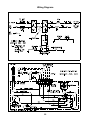
1
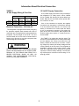
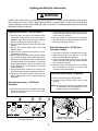
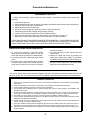
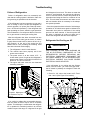
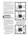
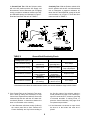
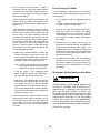
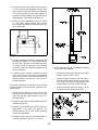
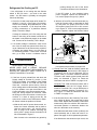
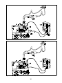
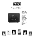
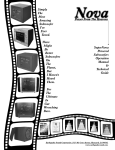
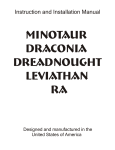
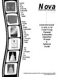
Norcold Repair Guide
Models 322, 323
Table of Contents
Page
12-2 Specifications & Operating Limits
12-2 General Instructions
12-3 Electrical Connections
12-4 Description of Operation
12-5 Lighting & Start-Up Instructions
12-6 Preventative Maintenance
12-7 Troubleshooting
12-17 Removal & Replacement Procedure
12-22 Wiring Diagrams
1
Section 12
General Information and Specification
Operating Limits - Models 322, 323
Current Draws - 322, 323
AC Mode: 132 VAC Max., 108 VAC Min.
AC Heating Element - 1.3 amps @ 110 Volts AC
1.4 amps @ 120 Volts AC
DC Mode*: 15.4 VDC Max., 11.5 VDC Min.
DC Heating Element* - 11.7 amps @ 12 Volts DC
13.6 amps @ 14 Volts DC
Gas Mode: 11" W.C. Gas Supply ± 0.5" W.C.
10.5" W.C. Min. Burner Pressure
(High Fire)
Fuse Replacement Data
(Refrigerator Control Panel)
Models 322, 323 Ratings
AC Circuit: 3 amp Type 3AG (1 1/4" x 1/4")
Norcold Part No.: 61654622
LP Gas Mode: 640 BTU/Hr Input
11" W.C. Gas Supply
.010" Orifice (LP10)
DC Circuit: 20 amp Type 3AG (1 1/4" x 1/4")
Norcold Part No.: 61440522
AC Mode: 110 Volts AC, 140 Watts
Gas Circuit: None
DC Mode*: 12 Volts DC, 140 Watts
* 3-Way Models Only (Model 323)
General Instructions - Models 322, 323
c. Adequate seal between refrigerator mounting
flange and cut-out opening.
d. Installed on a solid floor (not on carpet) and sec
u
r
e
d
by screws through holes provided.
THIS REFRIGERATOR IS NOT INTENDED TO BE
OPERATED AS A FREE STANDING UNIT (I.E.
WHERE THE PRODUCTS OF COMBUSTION ARE
NOT COMPLETELY SEALED OFF FROM THE LIVING AREA) OR INSTALLED IN SUCH A WAY AS
TO CONFLICT WITH THESE INSTALLATION INSTRUCTIONS. UNAPPROVED INSTALLATIONS
COULD RESULT IN SAFETY RISKS OR PERFORMANCE PROBLEMS.
The refrigerator described herein is designed and
certified for built-in installations.
WARNING
Model 323 is shipped from the factory as a 3-Way
model to operate on propane gas, 120 volts AC or
12 volts DC.
Model 322 is shipped from the factory as a 2Way unit to operate on propane gas or 120 volts
AC electric.
To confirm that the installation is adequate, check for:
a. Adequate ventilation (See Section 2 on "Ventilation Requirements").
b. Both gas and electrical components installed
and operating in a safe condition.
2
Information About Electrical Connection
TABLE 1
12 Volt Supply Wiring & Fuse Size
12 Volt DC Supply Connection
A 12 volt DC supply connection is only necessary if
the refrigerator is a 3-Way model - either a Model
323 or a Model 322 with the DC option added by a
dealer. Both the AC and GAS modes operate without a need for 12 volts.
2-Way Models
3-Way Models
min. wire max. fuse min. wire max. fuse
size
size
size
size
0-20’
18 AWG 6 Amp 12 AWG 20 Amp
over 20’ 18 AWG 6 Amp 10 AWG 30 Amp
If the 12 volt connection is required, the negative
connection from the battery is connected to terminal
5 on the terminal block and the +12 volt from the
battery is connected to an in-line fused wire which,
in turn is connected to terminal 6. See wiring diagram at the end of this section. Both negative and
positive supply wires require 1⁄4" female quick connect terminals.
Electrical Connection - 120 Volts AC
The refrigerator is equipped with a three prong plug
for protection against shock hazard and must be
connected into a recognized three prong attachment
receptacle. The free length of cord is 24". The cord
must be routed so as not to come in contact with the
burner cover, flue pipe or any other component that
could damage the cord insulation.
See TABLE 1 for supply wire and fuse sizing. The
wire size is determined by the DC load (heater draw)
and the distance the current must travel from the
battery. Should the wire size be too small, a resulting voltage drop reduces the heater wattage and the
cooling capacity in the DC mode. The refrigerator is
designed to operate at full cooling capacity, unlike
other RV refrigerators which operate at a reduced
capacity to conserve battery drainage. The DC heating element has a continuous current rating of 11.6
amps @ 12VDC.
WARNING
DO NOT REMOVE (CUT) GROUNDING PRONG
FROM THE REFRIGERATOR AC POWER CORD.
REMOVAL OF THIS PRONG CAN RESULT IN A
SEVERE ELECTRICAL SHOCK, AS WELL AS
VOIDING THE REFRIGERATOR ELECTRICAL
CERTIFICATION AND WARRANTY.
3
Operation
The GAS mode utilizes an adjustable GAS control. The control can be manually adjusted to meter the fixed amount of propane gas to the burner
thereby acting as a temperature control to maintain cabinet temperature.
The controls are designed so that each mode of
operation is independent of the other. All electricity
could be cut off and the refrigerator still operate in
the GAS mode. 12 Volts is not necessary to operate
the control circuit.
Important: Unlike an automatic gas control, this control does not cycle the flame from high
fire to low fire as with other types of RV
refrigerators. If the cooling load changes,
the GAS control must be manually adjusted to maintain the same temperature.
Gas Mode
The GAS mode uses a thermocouple system to
produce a self-generating power (milli-volts). The
Thermocouple, when heated by the burner flame,
produces enough milli-volts to hold the safety valve
open. A loss of flame de-energizes the safety valve
and shuts the propane gas down.
The gas ignition method uses a piezo spark ignitor
- requiring a manual ignition of the burner. See the
Lighting Instructions.
An Interrupter device is coupled in series with the
thermocouple so that the milli-amps cannot flow to
the Safety Valve (part of the Control Valve) until the
Interrupter contacts are shunted (jumpered). The
shunt is provided by the Selector switch when it is
switched to GAS mode.
Electric Modes
The AC mode, and DC mode in the case of the 3Way model, is thermostatically controlled by a nonadjustable thermostat. The Thermostat has a capillary sensor attached to the cooling fin. The electric
heater (AC or DC) will cycle in response to the fin
temperature to maintain the cabinet temperature.
The Selector switch not only serves as a mode selector but also as an interlock between modes so
that two sources of power cannot be energized simultaneously.
4
Lighting and Start-Up Instructions
WARNING
DO NOT HOLD GAS VALVE (D) IN MORE THAN 30 SECONDS, IF FLAME IS NOT INDICATED WITHIN THIS
TIME, TURN GAS TO OFF, WAIT 2 MINUTES AND RETRY. CONTINUING TO HOLD GAS VALVE IN WILL
CAUSE GAS BUILD-UP IN THE BURNER AREA AND CAN RESULT IN AN EXPLOSION WHICH CAN CAUSE
PERSONAL INJURY OR DEATH.
Lighting Instructions - Gas Operation
2. Set the Energy Selector Switch (A) to the AC
position and verify that the Gas Control Selector
(D) is in the OFF position.
3. No other action is required since a non-adjustable thermostat is provided to prevent food from
freezing in the electric modes.
1. Open the lower vent door on the outside rear of
the vehicle to gain access to the rear of the refrigerator. Open window on front side of Burner
Box to view the burner shown in Figure 8.
2. Set the Energy Selector Switch (A) to the GAS
position.
3. Set the Gas Control Selector (D) to the HIGH
COOL position.
4. Ensure that the manual shut-off valve is open.
See location in Figure 1.
5. While pushing the Gas Control Selector switch
(D) in, press the spark ignitor push-button (B) in,
several times in rapid succession (A click should
be heard each time it is depressed.). The burner
should light; however, continue to hold the Gas
Control Selector (D) in for another 15 seconds
before releasing.
6. Verify that the flame remains lit by looking at the
burner through the burner box window in Figure 8.
7. Adjust the Gas Control Selector (D) to the desired cooling setting. Close viewing window on
Burner Box.
Start-Up Instructions - DC Electric
Operation (3-Way)
1. Verify that 12 volts DC is available to the refrigerator and that the in-line DC fuse in the DC
heater wire assembly is operational.
2. Set the Energy Selector Switch (A) to the DC
position and verify that the Gas Control Selector
(D) is in the OFF position.
3. No other action is required since a non-adjustable thermostat is provided to prevent food
freezing in the electric modes.
Shut-Down Instructions - All Models
1. Set the Gas Control (D) to OFF position.
2. Set the Energy Selector Switch (A) to GAS
position.
Start-Up Instructions - AC Electric
Operation
NOTE: The Gas Control and Energy Selector must
be switched to the above positions to completely shut down the refrigerator.
1. Verify that 120 volts AC is available to the refrigerator and that the AC fuse (C) in the control
bracket is operational.
*
*
Manual Shut-Off Valve
(shown in open position)
323 models & 322
model with DC add-on
5
Figure 1
Preventative Maintenance
Maintenance Check List
A safety and performance check should be made annually. The schedule should include at least the
following:
a.
b.
c.
d.
e.
f.
g.
h.
i.
Leak test the gas lines.
Check combustion seal; repair or replace, if necessary (Visual check without removing the refrigerator.).
Inspect or clean the burner or burner orifice.
Check/adjust the electrode spark gap.
Insure the Thermocouple tip is clean and secure in the burner bracket.
Check/adjust AC and DC voltages and gas supply pressure.
Check the Flame Failure Safety Device (See procedure below).
Insure that the area around the burner and controls is free of debris, oily rags, etc..
Inspect the controls, piping and wiring to insure that they are in good condition.
THESE MAINTENANCE PROCEDURES MUST BE PERFORMED BY A QUALIFIED SERVICE PERSON. NORCOLD CANNOT ACCEPT RESPONSIBILITY FOR REPAIRS, ADJUSTMENT, OR MAINTENANCE PERFORMED BY OTHER THAN A QUALIFIED DEALER OR SERVICE CENTER.
Check-Out of Flame Failure Safety Device
this device closes.).
4. Turn the gas back on at the manual gas input
shutoff valve.
5. Attempt to relight the burner by pressing the
spark ignitor push-button rapidly in succession
but without pressing the Gas Control Selector in.
6. If the burner cannot be re-ignited without holding
the Gas Control Selector in, the flame failure
safety device has operated correctly.
1. To verify proper operation of the flame failure
safety device, first start the system in the gas
mode and verify the presence of a steady flame.
2. Turn off the gas at the manual gas input shutoff
valve.
3. The flame will go out and within three minutes,
the flame failure safety device should automatically close (A sharp click should be heard as
The service facility should review with the refrigerator owner the preventative maintenance steps which can be
performed by the user. The check list is printed in the Installation and Operating Instructions and repeated here.
Owner’s Check List
1. Keep the food compartment clean (See section on Cleaning the Refrigerator in the Installation and Operating
Instructions).
2. Check for frost build-up (See section on Defrosting in the Installation and Operating Instructions).
3. Check for proper draining of the fins in the fresh food compartment.
4. Insure that the food compartment door is sealing properly (See section on Door Sealing in the Installation and
Operating Instructions).
5. Be alert to noticeable changes in cooling performance, either overcooling or poor cooling. If this happens without changes in other factors such as weather or resetting of thermostat, contact your dealer or Service Center.
6. Insure that your LP gas supply is Propane, not other types such as Butane or Butane mixtures.
7. Check the flame appearance during operation in the GAS mode (See section on Gas Flame Appearance in the
Installation and Operating Instructions).
8. Inspect the floor at the rear of refrigerator (Look through intake vent from outside of coach). If water appears frequently, contact your dealer of Service Center.
9. Insure the ventilation space behind the refrigerator (the area from the bottom intake vent, up the back of the refrigerator and to the top exhaust vent) is clear of obstructions (insulation, supports, bird or squirrel nests, etc.).
10. Insure that the area directly behind the refrigerator is not being used for storage, particularly for storage of combustible material.
6
Troubleshooting
Failure of Refrigeration
and 6 degrees front to back. This does not mean the
system is non-functional, but requires the refrigerator to be removed from the vehicle and placed on its
right side when facing the front for a minimum of one
hour. This will allow the ammonia and water to mix
with one another which is necessary in the absorption system operation.
Failure of refrigeration does not necessarily indicate that the cooling system is defective. Other factors governing its operation must be checked.
If the refrigerator has been operating on gas and a
loss of cooling is noted, convert the refrigerator to
electric operation, AC power (See "Start-Up Instructions - AC Electric Operation"). If the refrigerator has
been operating on electric, switch it to gas operation.
This will determine if a component failure in the electric or gas controls is causing the cooling fault.
Once the system has been relieved of its blockage,
operation on AC should once again be initiated for a
reasonable time period to determine if the cooling
process has been restored. If after this period the
fins have no indication of cooling on either gas or
electric the refrigerator will have to be replaced.
After the refrigerator has been converted from one
power source to the other (gas to electric, or electric
to gas) allow several hours to assure the unit is cycling properly. At the end of the period the fins
should start to cool providing the following items
have been checked out thoroughly.
Refrigerator Not Cooling on AC
WARNING
1. The refrigerator is level in each direction.
2. The controls have been properly set for the
power source utilized.
3. The power source is at the correct 10.5 - 11
inches water column for gas at the refrigerator’s
pressure tap (Figure 2) and 108-132 volts AC for
electric or 11.5 to 15.4 volts DC.
4. The upper and lower vents are not obstructed
restricting ventilation.
USE EXTREME CAUTION WHEN WORKING ON
THE AC ELECTRICAL COMPONENTS OF THE
REFRIGERATOR. BEFORE REPLACING ANY
ELECTRICAL COMPONENT, DISCONNECT THE
AC POWER SOURCE TO THE REFRIGERATOR.
ELECTRICAL CURRENT CAN CAUSE SEVERE
ELECTRICAL SHOCK OR DEATH.
If the refrigerator is not cooling with the Selector
switch in the AC mode - yet cools in the gas mode the AC heater is probably not energized. Check the
following:
1. Check for 110 volts to the heater at AC Terminals 1 and 2 (See Figure 3 for location).
Connect Manometer
to Pressure Tap Tee
Figure 2
If no cooling is evident after a reasonable time period, the cause of failure may be due to a blocked
system. This blockage is caused when the refrigerator is operated for extended periods in an off-level
condition beyond the range of 3 degrees left to right
Figure 3 - Identification Terminal Block Connections
7
If there b.
is no reading, the possibilities are a) AC
supply not connected, b) 3 Amp fuse blown, c)
wiring connections, or d) defective switch or
thermostat. Proceed to Step 2.
If voltage is measured (108-132 volts), then the
heater or the wiring to the heater is defective or
the heater is not positioned properly in the heater
well. Proceed to the Continuity test in Step 4.
2. If no heater voltage is measured, disconnect the
AC supply cord and measure the voltage at the
AC receptacle. If no reading, determine why the
power is not connected. If voltage is present,
check fuse in next step.
GAS-AC-DC
Selector Switch
Figure 4 - Wiring Connections to Selector Switch
3. Without reconnecting the AC supply cord, check
condition of the 3 Amp fuse (should be 0 Ohms
using an Ohmmeter set at lowest scale); replace
if necessary and repeat Step 1 to insure there is
no secondary problem. If fuse blows a second
time, go to Step 4 since it indicates either a
shorted heater or a grounding fault.
WARNING
NEVER OVER FUSE A CIRCUIT. REPLACE
BLOWN FUSE WITH EXACT REPLACEMENT INDICATED BY NORCOLD. OVER FUSING OF A
CIRCUIT CAN RESULT IN A FIRE.
GAS-AC-DC
Selector Switch
Figure 5 - Thermostat Jumper Connection
If the fuse is good (and still no voltage to the
heater), the problem is an open circuit either in
the Control Assembly or the interconnecting wiring. Using the wiring diagram and Figure 4 as
reference, check the wiring for loose connections or incorrect connections. If a check of wiring proves OK, either the Thermostat or the Selector Switch has an open circuit. Isolate the
open4.circuit as follows:
b. With the AC cord disconnected, lay back
the Control panel as described in Step (a) and
place one jumper from AC2 to W2 and another jumper from AC1 to W1 according to
Figure 6. If AC is now energized when power
is applied, replace the Selector Switch per replacement procedure on page 12-20.
a. With the AC cord disconnected, unfasten the
Control Assembly and lay back to view the
control wiring - See the first four steps of the
selector switch removal procedure on page
12-20. Without removing any wires, place a
jumper across terminals W1 & W2 as illustrated
in Figure 5. Make sure the jumper is making
contact with the copper wire of metal terminal.
Note: Access to the terminals can be gained
by probing through the end of the Quick
Connectors as shown in the illustrations.
GAS-AC-DC
Selector Switch
If the AC heater is now energized when
power is applied, replace the Thermostat. If
not, remove jumper and go to (b).
Figure 6 - Selector Switch - Jumpers on AC Section
8
Continuity Test: With the Selector switch still in
the AC position and the AC cord disconnected,
use an Ohmmeter to measure resistance between the HOT and NEUTRAL prongs of the AC
cord connector, as in Figure 7. Read the Ohmmeter and refer to TABLE 2.
4. Ground Fault Test: With the Selector switch
still in the AC position and the AC Supply cord
disconnected, use an Ohmmeter (set on highest
scale) to measure resistance between the HOT
and GROUND prongs, as illustrated in Figure 7.
Read the Ohmmeter and refer to TABLE 2.
Figure 7 - Continuity Ground Fault Test - AC
TABLE 2
Ground Fault/Continuity Check
Test Points on AC Cord
Prongs (See Figure 7)
Ohmmeter Reading
Indication
Action
Hot Terminal & Prong
0 Ohms
(dead short)
Indicates a
grounding fault
Go to Step 5
Hot Terminal & Prong
Open Circuit
Normal condition
Hot & Neutral Terminals
76 - 85 Ohms*
above 85 Ohms or
below 76 Ohms
0 Ohms
(dead short)
Open Circuit
(no reading)
Heater is good
Heater is out
of tolerance
Indicates a short
in the AC circuit
Indicates an open
in the AC circuit
Hot & Neutral Terminals
Hot & Neutral Terminals
Hot & Neutral Terminals
Possibility of ground
fault is eliminated
Go to Step 7
Replace heater
Go to Step 5
Go to Step 6
* If the heater is hot when the measurement is taken, the correct resistance range is 82-91 Ohms.
5. If the Ground Fault or the Continuity Test measures a short (0 Ohms), this causes the 3 Amp
fuse to blow. Repeat the test where 0 Ohms was
measured but this time with the AC heater disconnected (Reason: to determine whether the
short is in the heater or the controls).
the first four steps of the selector switch removal procedure on page 12-20. Carefully inspect all connections for erroneous grounding
of electrical terminals. If nothing found, replace the Control Assembly. See page 12-18
for replacement procedure.
a. If the Ohmmeter still shows a short (0 Ohms),
the control panel has a short. Remove the
Control Assembly and lay back according to
b. If the Ohmmeter now shows an open circuit,
the short is in the heater and must be replaced.
9
Poor Cooling in AC Mode
6. If the Continuity Test indicated in TABLE 2
measures an open, remove the heater leads at
Terminals 1 & 2 and install a jumper across terminals 1 & 2 (See Figure 3 for location). Repeat
the Continuity Check.
If the refrigerator is cooling poorly in AC yet satisfactory in the GAS mode, the problem could be one
of the following:
If after installing the jumper, the Ohmmeter now
shows a short, the heater has the open circuit
and must be replaced. Remove jumper from terminals 1 & 2.
a. Low voltage to heater (or extremely high voltage).
b. Heater not within wattage specification
c. Heater not secure in heater well
If the Ohmmeter still shows an open, there is an
open circuit in the control panel (make sure the
Selector switch is still in the AC position and the
fuse is good). The control assembly should be
detached and layed back according to the first
four steps of the selector switch removal procedure on page 12-20. Make sure all the wiring is
correct according to the wiring diagrams and
Figure 4. If wiring is proper, remove the jumper
from terminal 1 & 2 and isolate the open in the
Control Assembly as follows:
1. Check for 110 volts to the heater at Terminals 1
and 2 (See Figure 3 for location). The voltage
range limitation is 108 - 132 Volts AC. Note: Do
not disconnect the heater when this measurement is taken. If voltage reading is acceptable,
go to Step 2.
2. Disconnect the AC supply cord and use an
Ohmmeter to measure the HOT and NEUTRAL
prongs of the AC connector, as in Figure 7. The
measurement must be between 76 Ohms and
85 Ohms (or, if the heater is still hot, between 82
ohms and 91 ohms). Replace the heater if outside these stated limits.
a. With the AC cord disconnected, unfasten the
Control Assembly and lay back to view the
control wiring as described above. Without removing any wires, place a jumper across terminals W1 & W2 as illustrated in Figure 5.
3. If measurements in Steps 1 & 2 are acceptable,
the problem is not in the electrical circuit. Inspect
the heater installation to insure the heater is inserted to the "stop" bead and there is no physical damage.
Note: Access to the terminals can be gained
by probing through the end of the Quick
Connectors as shown in the illustrations.
Refrigerator Not Functioning in Gas Mode
If the AC heater is now energized when
power is applied, replace the Thermostat. If
not, remove jumper and go to (b.) below.
WARNING
b. With the AC cord disconnected, lay back the
Control panel as described above and place
one jumper from AC2 to W2 and another
jumper from AC1 to W1 according to Figure 6.
If AC is now energized when power is applied,
replace the Selector Switch per replacement
procedure on page 12-20.
USE EXTREME CAUTION WHEN WORKING ON
OR NEAR A PROPANE GAS SYSTEM. DO NOT
SMOKE NEAR A PROPANE GAS SYSTEM. DO
NOT USE AN OPEN FLAME TO CHECK THE
PROPANE GAS SYSTEM FOR LEAKS. A LOOSE
PROPANE SUPPLY LINE CONNECTION ALLOWS
GAS VAPORS TO ESCAPE. IF YOU CAN SMELL
FUMES, YOU HAVE HALF THE INGREDIENTS
FOR AN EXPLOSION. AN EXPLOSION CAN RESULT IN SEVERE PERSONAL INJURY OR DEATH.
7. If the continuity test in Step 4 indicates normal
heater ohms (76-85), then the problem is not in
the electrical circuit. Make sure the supply voltage is within 108 to 132 volts range and check
heater position to insure it is securely installed
in its well.
Continued on next page.
10
VISUAL OBSERVATIONS
*
CAUTION
Check thermocouple position in flame. Refer to
Figure 8. The Thermocouple should be seated
securely in its bracket with the sensing end extended over the flame, as shown. Lack of proper
Thermocouple position can cause flame blowout
symptoms or failure to hold the flame when trying to ignite the burner.
DO NOT OVER-TIGHTEN THE CONNECTIONS
ON EITHER SIDE OF THE INTERRUPTER. THE
CORRECT PROCEDURE FOR BOTH CONNECTIONS IS TO TURN THE CONNECTOR UNTIL IT
IS FINGER TIGHT; THEN TIGHTEN IT A QUARTER TURN MORE.
*
Check the orange wires from the Interrupter
switch to the Selector switch to insure good connections from the Interrupter terminals to G3 & W3
on the Selector switch. Refer to Figures 9 and 10.
Figure 8 - Burner Assembly
*
Check thermocouple connection to the Interrupter and the Interrupter connection to the Gas
control insuring connections are tight. The same
flame failures as stated above can result from
loose connections.
Figure 9 - View of Interrupter Switch
Figure 10 - Orange Wire Connections
11
*
Check to insure the main gas pressure is set at
11" W.C. with only the refrigerator running. Then
check with all other gas appliances operating.
This check assures the main tank regulator is
properly functioning. Make sure the customer is
using propane, not a mixture of Butane, etc.
*
Check the flame appearance. Refer to Figure
11. The flame should emerge from all four
burner slots with a steady blue color without yellow or smoky tips.
Figure 11
*
*
The flame envelope should be centered into the
fire tube (See Figure 11). If the envelope hits on
the side of the fire tube, a noticeable decrease
in cooling could be observed. This condition
would be caused by physical damage to the
burner or fire tube.
Figure 12 - Flame Spreader Position
5. If the pressures are not as indicated in Step 3
and 4, check the following:
• Recheck the main gas pressure to the refrigerator is set at 10.5" to 11" W.C.
If extremely poor cooling is observed on Gas
mode only and all of the above observations
seem normal, make sure the flame spreader is
properly placed in the fire tube. See Figure 12
for proper position.
• Inspect the filter located in the inlet side of
the manual Gas Valve (Figure 13) to confirm
that it has not become dirty/plugged from
contaminates. If in doubt, replace the filter.
If the visual observations listed above do not identify
a cooling problem in the Gas mode, perform the following checks:
• Inspect the burner orifice to confirm it is the
correct size (LP10) and that it is clean.
1. Insure that the Selector switch is set for gas
operation and that the gas is turned on at the
tank, and that the manual shut-off valve is in
the ON position.
2. Connect a manometer to the pressure tap tee as
indicated by Figure 2.
3. Depress and rotate the gas control knob counterclockwise to the max. cool position. You
should show 10.5" to 11" W.C. NOTE: Keep the
control knob depressed.
4. Rotate the knob to the min. cool position the manometer should show 8.5" W.C. ± 0.5" W.C.
Figure 13
12
• If the above inspections do not show reasons
for incorrect pressure, the problem is in the
Control Valve. Replace the Control Valve referring to page 12-18 for replacement procedure.
The tip of the Thermocouple must not touch the
metal fire tube or any metal part; this condition
could prevent the flame from locking in.
If Thermocouple is correctly positioned and the
safety valve still does not hold the flame, use the
following procedure to isolate the problem:
If the refrigerator fails to light on GAS:
1. If the piezo lighter does not supply sparks to the
burner when depressed, check for correct adjustment of the electrode. It should be 1/8" max.,
1/16" min. above the burner. See Figure 8.
Make sure that the Energy Selector is set at
GAS and the Gas Control is set at HIGH COOL.
With a digital multimeter set to read milli-volts,
connect probe lead (A) to one of the Interrupter
terminals as illustrated in Figure 14 (do not remove the orange wires from the Interrupter terminals although you may need to raise them
slightly to allow the probe to touch the terminal).
Connect the other probe lead (B) to the copper
thermocouple tubing. Ignite and maintain a
flame at the burner by continually holding in the
Gas Control knob. Observe the milli-volt reading. Then move probe A to the other terminal
and observe the milli-volt reading. The problem
can be isolated as follows:
If the Electrode position is correct and there is
still no spark when rapidly depressing the red
piezo button, inspect the ignitor wire from the
Electrode to the Piezo lighter to insure good
connections and that it is not grounded through
skinned insulation, etc.
If the Piezo still does not produce sparks, the
Piezo Ignitor must be replaced. See page 12-19
for replacement procedure.
2. If the flame does not hold the safety valve open
(flame goes out when Gas Control is released)
in the GAS mode, check that the thermocouple
is tight and that the gas pressure is correct at
11" W.C..
CAUTION
DO NOT OVER-TIGHTEN THE CONNECTION ON
EITHER SIDE OF THE INTERRUPTER. THE CORRECT PROCEDURE FOR BOTH CONNECTIONS
IS TO TURN THE CONNECTOR UNTIL IT IS FINGER
TIGHT; THEN TIGHTEN IT A QUARTER TURN MORE.
Figure 14 - Measuring Thermocouple milli-volts
Thermocouple Troubleshooting Table
Milli-Volt Reading
4-19 milli-volts read at both
Interrupter terminals
0 milli-volts read at both
Interrupter terminals
High milli-volt reading (20-30) on
one Interrupter terminal 0 milli-volts
on other
High milli-volts (20-30) on both
Interrupter terminals
13
Diagnosis
This is a normal reading indicating
problem is mechanical, not electrical.
Thermocouple functioning properly.
Defective Gas Control Valve; replace
per procedure on page 12-18.
Defective Thermocouple; replace
per procedure on page 12-19.
Thermocouple OK if orange wires
properly connected to W3 & G3 from
the Interrupter, replace the Control
Valve and Interrupter per procedure
on page 12-18.
Defective Gas Control Valve; replace
per procedure on page 12-18.
Refrigerator Not Cooling on DC
probing through the end of the Quick
Connectors as shown in the illustrations.
If the refrigerator is not cooling with the Selector
switch in the DC mode - yet cools in the other
modes - the DC heater is probably not energized.
Check the following:
If the DC heater is now energized when
power is applied, replace the Thermostat. If
not, remove jumper and go to (b.) below.
1. Check for 12 volts to the heater at DC heater Terminals 3 (+) and 4 (-). See Figure 3 for location.
If there is no reading, the possibilities are a) DC
supply not connected, b) 20 Amp fuse blown,
c) wiring connections, or d) defective Selector
switch. Proceed to Step 2.
b. With the AC and DC power disconnected, lay
back the Control panel as described in Step
(a) and place one jumper from DC2 to W2
and another jumper from DC1 to W1 according to Figure 15. If DC is now energized when
power is applied, replace the Selector Switch
If voltage is measured (10.5-15.4 volts), then the
heater or the wiring to the heater is defective or
the heater is not positioned properly in the heater
well. Proceed to the Continuity Test in Step 4.
2. If no heater voltage is measured, check condition of the 20 Amp fuse (should be 0 Ohms using an Ohmmeter set at lowest scale); replace if
necessary and repeat Step 1 to insure there is
no secondary problem. If fuse blows a second
time, go to Step 4 since it indicates either a
GAS-AC-DC
Selector Switch
WARNING
Figure 15 - Selector Switch with Jumper on DC Section
shorted heater or a grounding fault.
NEVER OVER FUSE A CIRCUIT. REPLACE
BLOWN FUSE WITH EXACT REPLACEMENT INDICATED BY NORCOLD. OVER FUSING OF A
CIRCUIT CAN RESULT IN A FIRE.
per replacement procedure on page12-20.
4. Ground Fault Test: With the Selector switch still
in the DC position, disconnect the DC Supply at
Terminals 5 and 6. Use an Ohmmeter (set on
highest scale) to measure resistance between
Terminal 6 and chassis ground (metal panel will
work), as illustrated in Figure 16. Read the
Ohmmeter and refer to TABLE 3 on page 12-16.
3. If the fuse is good, reinstall fuse and check the
Supply voltage at Terminal 5 (-) and 6 (+). See
Figure 3 for location. If no reading or if the voltage
is outside the limits of 10.5 Volts min. and 15.4
Volts max., correct the power source. If there is
still no voltage at the heater terminals (Terminals 3
& 4), the problem is an open circuit either in the
Control assembly or the interconnecting wiring.
Using the wiring diagram as reference, check
the wiring for loose connections or incorrect connections. If a check of wiring proves OK, the
open circuit is either in the Thermostat or Selector Switch. Isolate the problem as follows:
Continuity Test: With the Selector switch still in
the DC position and the DC Supply disconnected at Terminals 5 & 6, use an Ohmmeter to
measure resistance between Terminals 5 & 6,
as in Figure 17. Read the Ohmmeter and refer
to TABLE 3 on page 12-16.
5. If the Ground Fault or the Continuity Test measures a short (0 Ohms), this causes the 20 Amp
fuse to blow. Repeat the test where 0 Ohms was
measured but this time with the DC heater disconnected (Reason: to determine whether the
short is in the heater or the controls).
a. With the AC and DC power disconnected, unfasten the Control Assembly and lay back to
view the control wiring - per removal procedure on page 12-18. Without removing any
wires, place a jumper across terminals W1 &
W2 as illustrated in Figure 5.
If the Ohmmeter still shows a short (0 Ohms), the
control assembly has a short and must be replaced. See page 12-18 for replacement procedure.
Note: Access to the terminals can gained by
If the Ohmmeter now shows an open circuit, the
14
Figure 16 - Ground Fault Test - DC
Figure 17 - Continuity Test - DC
15
TABLE 3
DC Ground Fault/Continuity Check
Test Points
Terminal 6 & Chassis
See Figure 16
Terminal 6 & Chassis
See Figure 16
Terminal 5 & 6
See Figure 17
Ohmmeter Reading
0 Ohms
(dead short)
Indication
Action
Indicates a grounding fault
Go to Step 5
Open Circuit
Normal condition
Possibility of ground
fault is eliminated
1.21 - 1.37 Ohms*
Heater is good
Go to Step 7
Terminals 5 & 6
See Figure 17
above 1.37 Ohms or
below 1.21 ohms
Heater is out of tolerance
Replace heater per
replacement procedure
on page 12-17
Terminals 5 & 6
See Figure 17
Terminals 5 & 6
See Figure 17
0 Ohms
(dead short)
Open Circuit
(no reading)
Indicates a short in the
AC circuit
Indicates an open in the
AC circuit
Go to Step 5
Go to Step 6
* If the heater is hot when the measurement is taken, the correct resistance range is 1.3 - 1.47 Ohms.
on page 12-18. Without removing any wires,
place a jumper across terminals W1 & W2 as
illustrated in Figure 5.
short is in the heater and must be replaced.
6. If the Continuity Test indicated in TABLE 3
measures an open, remove the heater leads at
Terminals 3 & 4 and install a jumper across terminals 3 & 4 (See Figure 17 for location). Repeat the Continuity Check.
Note: Access to the terminals can be gained by
probing through the end of the Quick
Connectors as shown in the illustrations.
If after installing the jumper, the Ohmmeter
now shows a short, the heater has the open
circuit and must be replaced. Remove jumper
from terminals 3 & 4.
If the DC heater is now energized when
power is applied, replace the Thermostat. If
not, remove jumper and go to (b.) below.
b. With the AC and DC power disconnected, lay
back the Control panel as described above
and place one jumper from DC2 to W2 and
another jumper from DC1 to W1 according to
Figure 15. If DC is now energized when
power is applied, replace the Selector Switch
per replacement procedure on page 12-20.
If the Ohmmeter still shows an open, there is
an open circuit in the control panel (make sure
the Selector switch is still in the DC position).
The control assembly should be pulled out to
make sure all the wiring is correct. See page
12-18 for removal procedure and wiring diagrams to aide in tracing the wiring connections. Remove jumper from terminal 3 & 4. If a
check of wiring proves OK, either the Thermostat or the Selector is has an open circuit. Isolate the open circuit as follows:
7. If the continuity test in Step 4 indicates normal
heater ohms (1.21-1.37), then the problem is not
in the electrical circuit. Make sure the supply
voltage is within 10.4 to 15.4 volts range with the
heater operating, and check heater position to
insure it is securely installed in its well.
a. With the AC and DC power disconnected, unfasten the Control Assembly and lay back to
view the control wiring - per removal procedure
16
Removal & Replacement Procedures
AC Heater Removal & Replacement
Reinstall the insulation around the flue tube
making sure the insulation completely surrounds the flue tube.
WARNING
8. Tape the insulation closed.
9. Insure that the insulation does not obstruct the
opening in the flue tube.
USE EXTREME CAUTION WHEN WORKING ON
THE AC ELECTRICAL COMPONENTS OF THE
REFRIGERATOR. BEFORE REPLACING ANY
ELECTRICAL COMPONENTS, DISCONNECT THE
AC POWER SOURCE TO THE REFRIGERATOR.
ELECTRICAL CURRENT CAN CAUSE SEVERE
ELECTRICAL SHOCK OR DEATH.
10. Reconnect the AC Heater leads to the AC
Heater terminals (Terminals 3 & 4 in Figure 10).
11. Reconnect the AC power cord to the AC receptacle.
1. Disconnect the AC power cord from the AC receptacle.
2. Disconnect the two AC Heater leads from the
terminal block located on top of the control panel
(Terminals 1 & 2 in Figure 10).
DC Heater Removal & Replacement
1. Disconnect the DC input leads from the refrigerator, tape the positive terminal to prevent
shorting to any metal surface and blowing the
input fuse.
3. Remove the screw which secures the Flue Extension tube and swing it out of the way.
4. Remove the insulation that surrounds the flue
tube. Use a utility knife and cut the insulation
vertically - starting above the heater.
2. Insure that the Mode Selector is set for DC operation, this eliminates other energy sources
from being activated.
5. Lift the AC Heater from the heater well.
3. Disconnect the DC Heater leads from the heater
terminals located on top of the control panel
(Terminals 3 & 4 in Figure 10).
6. Reinstall the new heater into the well until the
stop bead on the heater touches the heater well
(See Figure 18).
4. Remove the screw which secures the Flue Extension tube and swing it out of the way.
5. Remove the insulation that surrounds the flue
tube. Use a utility knife and cut the insulation
vertically - starting above the heater.
6. Remove the DC Heater from the heater well.
7. Install the replacement the heater well, gliding
it in until the bead stop on the heater touches
the well.
8. Reinstall the insulation around the flue tube
making sure the insulation completely surrounds
the flue tube.
9. Tape the insulation closed.
10. Reconnect the heater leads to the DC Heater
terminals (Terminals 3 & 4 in Figure 10).
11. Insure that the 20 AMP fuse is installed in the in
line fuse holder.
Figure 18
17
Block, tagging each wire or otherwise identifying
for reconnection later.
WARNING
WARNING
NEVER OVERFUSE A CIRCUIT. REPLACE BLOWN
FUSE WITH EXACT REPLACEMENT INDICATED
BY NORCOLD. OVERFUSING OF A CIRCUIT CAN
RESULT IN A FIRE.
USE TWO WRENCHES WHEN TIGHTENING OR
UNTIGHTENING GAS FITTINGS. LEAK TEST AFTER WORKING ON ALL GAS FITTINGS. FAILURE
TO DO SO COULD RESULT IN A GAS LEAK
WHICH COULD RESULT IN A FIRE OR EXPLOSION, WHICH COULD CAUSE PERSONAL INJURY OR DEATH.
12. Reconnect the DC input leads to the terminal
block (See Figure 10). Insure that the correct
polarity is observed.
3. Remove the inlet flare fitting to the Gas Control
Valve.
Manual Shut-off Valve Removal
& Replacement
4. Remove the outlet flare fitting from the Gas Control Valve.
WARNING
5. Remove the screw that secures the Control Assembly to the cabinet.
USE TWO WRENCHES WHEN TIGHTENING OR
UNTIGHTENING GAS FITTINGS. LEAK TEST AFTER WORKING ON ALL GAS FITTING. FAILURE
TO DO SO COULD RESULT IN A FIRE OR EXPLOSION WHICH COULD CAUSE PERSONAL INJURY OR DEATH.
6. Lift the Control Assembly away from the cabinet.
7. Remove the clips that secure the capillary tube
to the fins, noting that the capillary tube is located on the fifth fin from the right.
8. Pull the capillary tube through the back of the
cabinet.
1. Turn off the gas supply at the main tank.
9. To reinstall, reverse the above procedure.
2. Remove the inlet gas supply line from the shutoff valve connector (flare fitting).
10. Leak test all gas fittings removed.
3. Remove the outlet tube fitting from the shut-off
valve connector (flare fitting).
Gas Control Removal & Replacement
Note: Do not remove the brass fittings attached
to the valve body.
4. Remove the two screws from the shut-off valve
bracket.
WARNING
5. Remove the two screws that secure the shut-off
valve to the bracket.
USE TWO WRENCHES WHEN TIGHTENING OR
UNTIGHTENING GAS FITTINGS. LEAK TEST AFTER WORKING ON ALL GAS FITTINGS. FAILURE
TO DO SO COULD RESULT IN A GAS LEAK
WHICH COULD RESULT IN A FIRE OR EXPLOSION WHICH COULD CAUSE PERSONAL INJURY
OR DEATH.
6. To reinstall follow the reverse order 5 through 1.
7. Leak test all gas fittings removed.
1. Turn off the gas supply at the main tank and at
the manual shut-off valve.
Control Assembly Removal
& Replacement
2. Remove the inlet tube flare fitting from the Gas
Control Valve.
1. Turn off the gas supply at the main tank.
2. Remove all wire connections from the Terminal
18
3. Remove the outlet tube flare fitting from the Gas
Control Valve.
Note: Do not remove the brass elbows from the
valve body.
9. To reinstall the Thermocouple reverse the above
procedure.
10. Leak test all gas fittings removed.
4. Remove the two screws that secure the Gas
Control Valve to the Control Assembly.
Piezo Lighter Removal & Replacement
5. Remove the two red wires from the Thermocouple Adaptor.
WARNING
6. Remove the Thermocouple from the Thermocouple Adapter.
7. Remove the Thermocouple Adapter from the
Gas Control Valve.
USE TWO WRENCHES WHEN TIGHTENING OR
UNTIGHTENING GAS FITTINGS. LEAK TEST AFTER WORKING ON ALL GAS FITTINGS. FAILURE
TO DO SO COULD RESULT IN A GAS LEAK
WHICH COULD RESULT IN A FIRE OR EXPLOSION, WHICH COULD CAUSE PERSONAL INJURY OR DEATH.
8. To install a new Gas Control Valve reverse the
above procedure.
9. Leak test all gas fittings removed.
1. Turn off the gas supply at the main tank.
2. Remove the burner box cover.
Thermocouple Removal & Replacement
3. Remove the screw that secures the spark electrode to the burner bracket.
WARNING
4. Remove the electrode from the burner bracket.
5. Remove the flare fitting from the Gas Control
Valve inlet fitting.
USE TWO WRENCHES WHEN TIGHTENING OR
UNTIGHTENING GAS FITTINGS. LEAK TEST AFTER WORKING ON ALL GAS FITTINGS. FAILURE
TO DO SO COULD RESULT IN A GAS LEAK
WHICH COULD RESULT IN A FIRE OR EXPLOSION, WHICH COULD CAUSE PERSONAL INJURY OR DEATH.
6. Remove the flare fitting from the Gas Control
Valve outlet fitting.
7. Remove the screw that secures the Control Assembly to the cabinet.
1. Turn off the gas supply at the main tank.
8. Lift the Control Assembly away from the cabinet.
2. Remove the inlet tube flare fitting from the Gas
Control Valve.
9. Remove the nut that secures the Piezo Lighter
to the Control Assembly and remove the Piezo
Lighter.
3. Remove the outlet tube flare fitting from Gas
Control Valve.
10. To reinstall reverse the procedure.
4. Remove the two screws that secure the Gas
Control Valve to the Control Assembly.
11. Leak test all gas fittings removed.
5. Remove the Thermocouple from the Thermocouple Adapter.
6. Remove the burner box cover.
7. Remove the two screws that secures the Thermocouple bracket to the bracket.
8. Pull the Thermocouple out of the Thermocouple
bracket.
19
Thermostat Removal & Replacement
1. Turn off the gas supply at the main tank.
2. Remove the flare fitting from the inlet tube of the
Gas Control Valve.
WARNING
3. Remove the outlet tube flare fitting from the Gas
Control Valve.
USE TWO WRENCHES WHEN TIGHTENING OR
UNTIGHTENING GAS FITTINGS. LEAK TEST AFTER WORKING ON ALL GAS FITTINGS. FAILURE
TO DO SO COULD RESULT IN A GAS LEAK
WHICH COULD RESULT IN A FIRE OR EXPLOSION, WHICH COULD CAUSE PERSONAL INJURY OR DEATH.
4. Remove the screws that secures the Control Assembly to the cabinet.
5. Lift the Control Assembly away from the cabinet.
6. Remove the selector switch knob.
1. Turn off the gas supply at the main tank.
7. Remove the two screws that secure the selector
switch to the Control Assembly.
2. Remove the inlet flare fitting to the Gas Control
Valve.
8. Lift the selector switch away from the control
bracket.
3. Remove the outlet flare fitting from the Gas Control Valve.
9. Remove the wires from the selector switch one
at a time and connect to the new switch exactly
as removed. Double check the wiring connections with the wiring diagrams as follows:
4. Remove the screw that secures the Control Assembly to the cabinet.
5. Lift the Control Assembly away from the cabinet.
Orange wires to G3 & W3
Red wires from Thermostat to W2 & W3
Red wires from fuse & terminal block to AC1
& AC2
Blue wires to DC1 & DC2
6. Remove the two screws that secure the
Thermostat to the Control Assembly.
7. Remove the two red wires from the Thermostat.
8. Remove the clips that secure the capillary tube
to the fins, noting that the capillary tube is located on the fifth fin from the right.
10. To reinstall, reverse Steps 7-1.
11. Leak test all gas fittings removed.
9. Pull the capillary tube through the back of the
cabinet.
10. To reinstall reverse the above procedure.
Orifice Removal & Replacement
11. Leak test all gas fittings removed.
WARNING
USE TWO WRENCHES WHEN TIGHTENING OR
UNTIGHTENING GAS FITTINGS. LEAK TEST AFTER WORKING ON ALL GAS FITTINGS. FAILURE
TO DO SO COULD RESULT IN A GAS LEAK
WHICH COULD RESULT IN A FIRE OR EXPLOSION, WHICH COULD CAUSE PERSONAL INJURY OR DEATH.
Selector Switch Removal & Replacement
WARNING
USE TWO WRENCHES WHEN TIGHTENING OR
UNTIGHTENING GAS FITTINGS. LEAK TEST AFTER WORKING ON ALL GAS FITTINGS. FAILURE
TO DO SO COULD RESULT IN A GAS LEAK
WHICH COULD RESULT IN A FIRE OR EXPLOSION, WHICH COULD CAUSE PERSONAL INJURY OR DEATH.
1. Turn off the gas supply at the main tank.
2. Remove the flare nut from the orifice assembly.
3. Remove the orifice assembly from the burner.
20
Refrigerator Removal & Reinstallation
Note: Do not attempt to remove the orifice body
from the brass adapter since the orifice is
pressed on at the factory to assure a
good seal.
1. Remove the AC cord from the AC receptacle.
2. Turn off the gas supply at the main tank.
4. Install orifice assembly, insure orifice assembly
is wrench tight in burner.
3. Remove the LP gas supply line from inlet fitting.
5. Reconnect flare nut to orifice assembly.
4. Remove the two screws from the back of the refrigerator that secure the refrigerator to the floor.
6. Leak test all gas fittings removed.
5. Remove the four screws from the breaker that
secure the refrigerator into the cut-out opening.
Burner Removal & Replacement
6. Slide the refrigerator forward and lift out of the
opening.
7. To reinstall, insure that the seal strips around
the breakers are in place and reinstall by reversing Steps 6 through 1.
WARNING
USE TWO WRENCHES WHEN TIGHTENING OR
UNTIGHTENING GAS FITTINGS. LEAK TEST AFTER WORKING ON ALL GAS FITTINGS. FAILURE
TO DO SO COULD RESULT IN A GAS LEAK
WHICH COULD RESULT IN A FIRE OR EXPLOSION, WHICH COULD CAUSE PERSONAL INJURY OR DEATH.
WARNING
CARE MUST BE EXERCISED UPON REMOVAL
AND RE-INSTALLATION OF THE REFRIGERATOR TO INSURE THAT THE SEAL STRIPS LOCATED BEHIND THE MOUNTING FLANGES ARE
NOT DAMAGED, MISPLACED OR MISALIGNED.
THESE SEALS SERVE AS A COMBUSTION SEAL
WHICH PREVENTS EXHAUST FUMES FROM ENTERING INTO THE LIVING QUARTERS.
1. Turn off the gas supply at the main tank.
2. Remove the flare nut from the burner orifice assembly.
3. Remove the burner box cover.
8. Leak test all gas fittings removed.
4. Remove the screw that secures the burner to
the burner bracket, and pull the burner from the
bracket.
5. Remove the orifice assembly from the burner.
6. To reinstall reverse the procedure.
7. Leak test gas fittings removed.
21
Wiring Diagrams
22