1
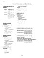
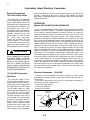
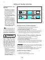
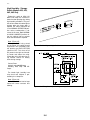
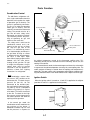
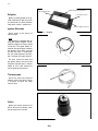
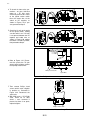
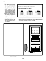
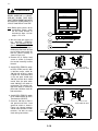
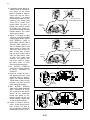
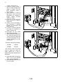
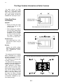
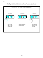
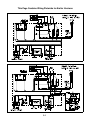
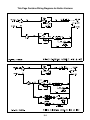
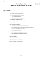
B101
Norcold Repair Guide
Models 442, 443, 452, 453, 462, 463, 482, 483
Table of Contents
Page
3-2 General Information and Specification
3-3 Information About Electrical Connections
3-3 Description of Operation
3-4 Location of Control and Components
3-5 Lighting and Operating Instructions
3-6 High Humidity and Interior Lamp Switch
3-7 Parts Function
3-10 Troubleshooting Procedures
3-10 Refrigerator Will Not Ignite Electrically on Propane
3-12 Refrigerator Does Not Indicate that a Flame has been Established
3-13 Burner Flame Will Not Light or Stay Lit
3-15 Refrigerator Overfreezing
3-15 Refrigerator Will Not Operate or Cool on A/C
3-18 Refrigerator Will Not Operate or Cool on D/C
3-21 Wiring Pictorials
3-23 Wiring Diagrams
3-E1 Information on Earlier Versions
3-W1 Wiring Pictorials for Earlier Versions
3-W3 Wiring Diagrams for Earlier Versions
3-1
Section 3
B101
General Information and Specification
OPERATING LIMITS - ALL
MODELS
AC Mode: 132 VAC Max., 108
VAC Min.
15.4 VDC Max., 10.5
VDC Min.
DC Mode: 15.4 VDC Max., 11.5
VDC Min.
Gas Mode: 11" W.C. Gas Supply
10.5" W.C. Min. Burner
Pressure (High Fire)
15.4 VDC Max., 10.5
VDC Min.
MODELS 442, 443
RATINGS
1050 Btu/Hr Input
LP Gas Mode:
11" W.C. Gas Supply
LP14 Orifice
12 Volts DC control voltage
AC Mode:
110 Volts AC, 200 Watts
DC Mode (3-Way only):
12 Volts DC
MODELS 452, 453
RATINGS
1200 Btu/Hr Input
LP Gas Mode:
11" W.C. Gas Supply
LP14 Orifice
12 Volts DC control voltage
AC Mode:
110 Volts AC, 200 Watts
DC Mode (3-Way only):
12 Volts DC
12 Volts DC control voltage
AC Mode:
110 Volts AC, 300 Watts
12 Volts DC control voltage
DC Mode (3-Way only):
12 Volts DC
MODELS 482, 483
RATINGS
1500 Btu/Hr Input
LP Gas Mode:
11" W.C. Gas Supply
LP16 Orifice
12 Volts DC control voltage
AC Mode:
110 Volts AC, 300 Watts
12 Volts DC control voltage
DC Mode (3-Way only):
12 Volts DC
CURRENT DRAWS - 442, 443, 452, 453
Relighter - 30 milliamps
AC Heating Element - 1.5 amps at 110 Volts AC
1.7 amps at 120 Volts AC
DC Heating Element - 9.2 amps at 12 Volts DC
10.7 amps at 14 Volts DC
CURRENT DRAWS - 462, 463, 482, 483
Relighter - 30 milliamps
Humidity Heater - 240 milliamps or .24 amps
Interior Lamp (when door open) - 600 milliamps or .60 amps
AC Heating Element - 2.7 amps at 110 Volts AC
2.9 amps at 120 Volts AC
DC Heating Element - 13.8 amps at 12 Volts DC
16.1 amps at 14 Volts DC
MODELS 462, 463
RATINGS
1450 Btu/Hr Input
LP Gas Mode:
11" W.C. Gas Supply
LP16 Orifice
3-2
B101
Information About Electrical Connection
Electrical Connection
120 Volts AC-400 Series
The refrigerator is equipped with
a three prong plug for protection
against shock hazard and must be
connected into a recognized three
prong attachment receptacle. The
free length of cord is 24", so it is
recommended that the receptacle
be located to the left side of the refrigerator (viewed from rear) and
approximately 12" from the floor.
This allows easy accessibility
through the vent door. The cord
must be routed so as not to come
in contact with the burner cover, flue
pipe or any other component that
could damage the cord insulation.
WARNING
DO NOT REMOVE (CUT) GROUNDING PRONG FROM THE REFRIGERATOR AC POWER CORD. REMOVAL OF THIS PRONG CAN RESULT IN A SEVERE ELECTRICAL
SHOCK, AS WELL AS VOIDING THE
REFRIGERATOR ELECTRICAL CERTIFICATION AND WARRANTY.
dictates the AWG wire size to be used. Should the wire be too small for the
distance, a voltage drop will result. In case of 3-Way models, the voltage
drop affects the wattage output of the cartridge heater and resultant refrigerator performance.
OPERATION
Models 442-443-452-453-462-463-482-483
All use a single combination control to determine and regulate the mode of
operation (LP GAS or Electric). The control is operated by two knobs, the
first to select the mode of operation (LP GAS or Electric); the second, to
control the thermostat setting. The control consists of a gas shut off valve,
safety valve, thermostat and electric interlock. The interlock prevents the
possibility of running on LP GAS and Electric at the same time. The safety
valve is built into the combination control, and is designed so that any loss of
flame will stop the gas flow to the burner. It is controlled by means of a thermocouple positioned in the gas flame. As long as a flame is detected by the thermocouple, the valve will remain open. In the event of flame failure, the valve
closes, shutting off the gas flow. To light or relight the burner, the gas control
knob must be depressed or held in until the relighter establishes a flame. The
relighter is made active by means of an illuminated rocker switch. When the relighter switch is in the on position it will illuminate, signaling that 12VDC is present and energizing the relighter to send a spark to the burner. It will continue
to spark until either a flame has been established or the switch is turned off.
On the 3-Way models (A/C, D/C and LP Operation), there is an A/C-D/C selector switch. To operate the refrigerator on 120VAC, set the mode selector
to ELEC and depress the A/C switch. If 120VAC is available, the refrigerator
will function on A/C current. To operate the refrigerator on D/C Electric while
traveling, leave the mode selector switch in ELEC position, and depress the
D/C switch for DC operation.
Electrical Connection - 12 Volt DC
12 Volts DC Connection 400 Series
The 12 volt DC supply is necessary for the flame ignition circuit in
the gas mode, the interior light, humidity heater, and to supply power
for 3-Way models in the DC mode.
The AC mode (2-Way or 3-Way
models) operates independently of
the 12 volt DC. The DC supply
connections are made at the terminal block provided at the rear of
the refrigerator. The terminal block
accepts wire connections with 1/4"
Quick Connect terminals. Correct
polarity must be observed when
connecting to the DC supply. The
distance the current must travel
from the battery to the refrigerator
12 volt DC must be connected (see Figure 3.1 below) at all times in order
to operate the electronic ignition system, and the interior light and high humidity circuit.
The 12 volt DC power source can be either a 12 volt "deep cycle battery" or
the vehicle’s convertor. Voltage Limits:
12 volts DC control voltage
15.4 volts DC maximum
10.5 volts DC minimum
Appliance
Connection
Convertor
To Refrigerator
Figure 3.1
Recommended 12 Volt Connection
3-3
12 volt
RV battery
A008
Component Location and
Identification (Single Door
Models)
A. Illuminated Ignition Switch
B. Flame On Indicator Lamp
C. Thermostat Control Knob
D. Combination Control Knob
1. Gas On/Electric Interlock
2. Push-In Safety Valve
E. AC/DC Mode Selector Switch
(3-Way models only)
F. Serial Identification Plate
F
A
Figure 3.2
B
C
D
E
Controls Location, Single Door Model
G
Component Location and
Identification (Two Door
Models)
A. Illuminated Ignition Switch
B. Flame On Indicator Lamp
C. Thermostat Control Knob
D. Combination Control Knob
1. Gas On/Electric Interlock
2. Push-in Safety Valve
E. AC/DC Mode Selector Switch
(3-Way models only)
F. Serial Identification Plate
G. Three Position Switch (See
page 3-6)
1. NORMAL
2. STORAGE
3. HIGH HUMIDITY
H. Interior Light Switch
F
A
Figure 3.3
B
Controls Location, Two Door Model
3-4
C
D
E
H
B101
Lighting and Operating Instructions
Lighting Instructions: Gas
Operation
1. Make certain that 12 Volts DC
is available to the refrigerator.
2. Turn on gas supply at the tank.
3. Set thermostat control to the
maximum cold setting.
4. Set ignitor switch to "ON" position. The light located on the
switch will illuminate if 12 volts
DC is present.
5. Push and turn the "ELEC-OFFGAS" control counter-clockwise
so that knob indicator points to
"GAS". Push the control knob
and hold it until the flame indicator illuminates (continuous
glow). Continue to hold approximately 5 seconds, then release.
The flame indicator will remain
on. If not, repeat this step.
Note:
The flame should ignite within 10
seconds. On initial refrigerator startup, it may take longer than 10 seconds to allow air to be purged from
the gas line, as indicated by the
flame indicator failing to illuminate.
WARNING
DO NOT HOLD GAS CONTROL
VALVE IN MORE THAN 30 SECONDS. IF FLAME IS NOT INDICATED WITHIN THIS TIME, TURN
GAS TO "OFF", WAIT 2 MINUTES
AND RETRY. FAILURE TO DO SO
CAN CAUSE GAS TO BUILD UP IN
BURNER AREA AND RESULT IN AN
EXPLOSION WHICH CAN CAUSE
PERSONAL INJURY OR DEATH.
6. Move thermostat control to desired setting.
7. The ignitor switch should be
left in the "ON" position during
gas operation. If the switch is
turned off, the refrigerator will
cycle normally. However, in
case of flame blowout, the relighter does not function.
Figure 3.4
2-Way Controls (Upper), 3-Way Controls (Lower)
Start-Up Instructions : AC Electric Operation
1. Make certain that 120 Volts AC is available to the refrigerator.
2. Set the thermostat control to desired setting.
3. Set "AC-DC" switch to "AC" position (3-Way models only).
4. Set ignitor switch to "OFF" position.
5. Push and turn the "ELEC-OFF-GAS" Control clockwise so that knob indicator points to "ELEC". Upon release, note that the knob moves toward you, indicating that the control is locked into electric position.
Start-Up Instructions: DC Electric Operation (3-Way only)
1. Make certain that 12 Volts DC is available to the refrigerator.
2. Set thermostat control to desired setting.
3. Set "AC-ELECTRIC STANDBY-DC" switch to "DC" position.
4. Set ignitor switch to "OFF" position.
5. Push and turn the "ELEC-OFF-GAS" control clockwise so that knob indicator points to "ELEC". Upon release, note that the knob moves toward
you, indicating that the control is locked into electric operation.
Operation Note:
Use the "ELEC-OFF-GAS" control to shut off all cooling operation (both
Gas and Electric). The "GAS IGNITOR" switch must be shut off independently to prevent unnecessary sparking.
On 3-Way models, use the "ELECTRIC STANDBY" position of the "AC-ELECTRIC STANDBY-DC" switch to temporarily shut off AC or DC operation.
Operation Shut-Down: All Modes
1. Set ignitor switch to "OFF" position.
2. Push and turn "ELEC-OFF-GAS" control to "OFF".
3-5
B101
High Humidity - Storage
Switch Models 462, 463,
482, 483 Only
Turning this switch to HIGH HUMIDITY will keep the surface between the door openings dry during
high humidity conditions. This position will also allow the interior light to
activate when the lower door is
opened. The switch should be left
in the NORMAL OPERATION position unless condensation is observed in this area. Both NORMAL
and HIGH HUMIDITY positions allow the cabinet light to activate
when the lower door is opened.
Note: (Figure 3.5)
When your RV is being stored
for the winter, this switch should
be placed in the STORAGE (light
off) position and ELEC-OFF-GAS
control to OFF. This shuts off all
DC power to the light and humidity heater and allows the refrigerator door to be left open for airing without chance of battery
drain during storage.
Figure 3.5
Humidity and Light Switch
Figure 3.6
Wiring Assembly - Humidity and Light Switch
Current Draw
Interior Lamp: 600 Milliamps
Humidity Heat Strip: 240 Milliamps
The interior light, humidity heat
strip circuit and relighter is protected by the 3 Amp fuse.
Note: (Figure 3.6)
A short circuit in the interior lamp
socket will cause constant fuse
blowing.
3-6
B101
Parts Function
Combination Control
The 400 Series refrigerators utilize a single combination control to
determine and regulate the mode
of operation (gas or electric). The
control is operated by two knobs.
The first is to select the operating
mode (gas or electric), and the
second is to control the thermostat
setting. The control consists of a
gas shut off valve, safety valve,
thermostat and electric interlock.
The interlock prevents the possibility of operating on gas and
electric at the same time.
The safety valve is built into the
combination control and is designed so that any loss of flame
will stop the gas flow to the
burner. It is controlled by means
of a thermocouple positioned in
the gas flame. As long as a flame
is detected by the thermocouple,
the valve is held open. Upon
flame failure (empty propane tanks
blowout, etc.) the valve closes,
shutting off the gas flow. To light
or relight the refrigerator, the gas
control knob must be pushed
and held in until the ignition establishes a flame. See "Lighting
Instructions" on refrigerator.
Note:
The combination control does
not have an "OFF" position on the
thermostat dial. To check the gas
pressure for low fire, set the
thermostat to the warmest position, and cool the thermostat capillary tube by use of a component
coolant or by placing it in a glass
of ice water. This forces the control
to low fire. To check for the high
fire pressure set the thermostat to
the coldest position and allow the
capillary tube to get warm.
In the normal gas mode, the
combination control modulates the
gas pressure to the burner. It
modulates between high fire and
low fire pressures in response to
Capillary Tube
Control Terminals
LP Gas Input Connection
Selector Switch and
Safety Valve
Burner Tube Connection
Burner Pressure Tap
Thermostat
Figure 3.7
Combination Control
the cabinet temperature sensed by the thermostat capillary tube. This
modulating burner pressure controls the burner efficiency and in turn, the
cooling in the cabinet.
In the normal electric mode, the thermostat opens and closes the microswitch
in response to the cabinet temperature sensed by the same capillary tube. The
switch contacts will always be closed when the capillary tube temperature is
above 50°F. An open switch at this temperature would indicate a broken capillary tube, defective switch or the mode indicator shaft is depressed or hung up.
Ignition Switch
When the ignition switch is turned on, 12 volt DC is applied to the relighter
(provided 12 volt DC is supplied to the refrigerator).
Figure 3.8
Ignition Switch
3-7
B101
Ground Connection
Relighter
Ignition Electrode Connection
+ 12 volt Connection
Applies sparking power to the ignition electrode to light the burner
and illuminates the flame indicator
lamp when a flame is established.
Indicator Light Connection
Ignition Electrode
Sends sparks to the burner to
light the flame.
Figure 3.9
Relighter
Note:
This Norcold is equipped with an
electronic ignition relighter. It automatically relights the flame should
it blow out. The Ignitor Switch, located on the control panel, activates
this relighter. If the switch is turned
off after the flame is established,
the gas mode operates normallybut is without the relight feature.
The User should be aware that
the Ignitor Switch must be turned
off (green light off) when in electric
mode, or else it will continue to
cause sparking at the burner.
Figure 3.10
Ignition Electrode
Figure 3.11
Thermocouple
Thermocouple
Senses the heat of the flame to
hold the safety valve open. If there
is no flame, it causes the safety
valve to close.
Orifice
Applies the correct amount of LP
Gas to the burner assembly, when
the input pressure is correct.
Figure 3.12A
Orifice
3-8
B101
Burner
Applies the correct amount of
heat to the cooling unit, when it is
supplied the correct amount of air
and LP Gas.
Figure 3.12B
Burner
AC Heating Element
Applies the correct amount of
heat to the cooling unit, when it is
supplied with the correct AC voltage. All current 120 Volt AC heater
will have black lead wires.
Figure 3.13
AC Heater
Figure 3.14
DC Heater
DC Heating Element
Applies the correct amount of
heat to the cooling unit, when it
is supplied with the correct DC
voltage. All current DC heaters
will have yellow lead wires indicating 12 Volts DC.
AC-DC Switch 3-Way
Models Only
Selects the Electric mode
(AC or DC operation). Also has
an ELECTRIC-STANDBY position to temporarily shut off AC
or DC operation.
3 Position Switch
Figure 3.15
AC - DC Switch
3-9
B101
Troubleshooting Procedures
Refrigerator Will Not
Ignite Electrically on
Propane
1. Check for 12 Volts DC between positive and negative
leads at the rear of the refrigerator. If not present, correct
source.
12 Volt Supply Wires
Figure 3.16
12 Volt Supply Check
Figure 3.17
Fuse Continuity Check
Figure 3.18
Controls Access
2. If 12 Volts DC is present, then
check the 3 Amp fuse for continuity. If open, then replace with
fuse of same size and rating.
WARNING
NEVER OVERFUSE A CIRCUIT.
REPLACE A BLOWN FUSE WITH
EXACT REPLACEMENT INDICATED
BY NORCOLD. OVERFUSING A
CIRCUIT CAN CAUSE A FIRE.
3. If preceding checks did not reveal the cause of malfunction,
then access to the control
panel is required per Figure
3.18. The first step in gaining
access is to remove the two
control knobs (A), then remove the (6) Phillips head
screws (B). Once the control
panel has been removed, you
need to remove the (2) Phillips head screws (C). Then
pull the control mounting
bracket forward. This allows
access to the controls.
3-10
B101
4. To check for loose wire connections, set your Volt-Ohm
meter to + 25 Volt scale.
Check for presence of 12 volts
at the Ignitor rocker switch
from the center wire of the
switch to DC negative, as
shown in Figure 3.19. If present, proceed to Step 5.
Figure 3.19
12 Volt Check at Blue and White Terminals
Figure 3.20
12 Volt Check at Orange and White Terminals
5. Check for 12 volts at the outlet
of the Ignitor switch, making
sure the switch is on. If 12 volts
is not present between the DC
negative and outlet wire, as
shown in Figure 3.20, replace
the switch. If 12 Volts is present,
then proceed to Step 6.
6. Refer to Figure 3.21. Disconnect the spark wire. To gain
access to the relighter, remove
the 2 phillips head screws.
Phillips Head Screws
Spark Wire
Figure 3.21
Relighter Access
7. Then remove Phillips head
screws which retain relighter
in position as illustrated in
Figure 3.22. Reconnect the
spark wire.
8. With VOM set to + DC 25 Volt
scale, check for 12 Volts
across + and - terminals. If
present, but there is no spark,
replace relighter.
Phillips Head Screws
Figure 3.22
12 Volt Check at White and Orange Terminals
3-11
B101
Refrigerator Indicates No
Flame Established
If the Flame Indicator is not illuminated, yet the Ignitor switch is
ON with 12 volts available to unit
and flame at burner, then check
the following:
1. Keep in mind that the Flame
Indicator will not illuminate
unless a flame has been established.
2. Set VOM to + 5 Volts scale.
You should read from 1.5 to 2
Volts DC at the terminals of the
Relighter shown in Figure 3.23.
If not, replace the Relighter.
3. With the Ignitor Switch on, and
a flame established, check first
that the wires to the flame indicator bulb are not reversed.
Properly wired would be: red
lead from bulb to brown harness wire; black lead from
bulb to white harness wire
shown in Figure 3.24.
4. With test probes at points indicated in Figure 3.23, you
should read on the 5 Volt DC
scale something less than 2
Volts. If voltage is present and
the Flame Indicator still does
not illuminate, then replace
Flame Indicator.
Figure 3.23 Flame Indicator Check at White and Brown Term.
Figure 3.24
Flame Indicator Check
3-12
B101
Flame will not stay lit
(Lights and Then Goes Out)
1. Remove the control knob and
depress the shaft with your finger
until it bottoms out as shown in
Figure 3.25. If refrigerator ignites and stays lit realign the
combination control and reinstall knob. If ignition does not
occur, proceed to next step.
2. When the burner ignites and
then goes out, this can be
caused by (1) thermocouple not
positioned properly in the flame
or (2) retaining clip not properly
installed. See Figure 3.26.
3. Another check to perform would
be to remove the control panel
and control mounting bracket as
shown in Figure 3.18. This will allow you to check the tightness of
the thermocouple connection
into the combination control
as shown in Figure 3.27.
4. If the preceding steps fail to allow the refrigerator to ignite,
the next check is the main line
gas pressure to the refrigerator. See the section on Gas
Pressure Checks.
5. If you read less than 11" water
column pressure, then your main
tank regulator must be adjusted.
Figure 3.25
Depressing Safety Valve Shaft
Retaining Clip
Figure 3.26
Thermocouple in Proper Position
Thermocouple Connection
WARNING
USE EXTREME CAUTION WHEN
WORKING ON OR NEAR A PROPANE
GAS SYSTEM. DO NOT SMOKE NEAR
THE PROPANE GAS SYSTEM. DO
NOT USE AN OPEN FLAME TO
CHECK TO CHECK THE PROPANE
SYSTEM FOR LEAKS. A LOOSE PROPANE SUPPLY LINE CONNECTION
ALLOWS GAS VAPORS TO ESCAPE.
IF YOU CAN SMELL FUMES, YOU
HAVE HALF THE INGREDIENTS
FOR AN EXPLOSION. AN EXPLOSION CAN RESULT IN A SEVERE
PERSONAL INJURY OR DEATH.
6. Check the gas pressure
through the Combination Control. Figure 3.28 shows where
the "U" tube is to be connected.
Figure 3.27
Thermocouple Connection
Figure 3.28
Location of Pressure Tap Fitting
Pressure Tap Fitting
3-13
B101
7. The adjacent chart specifies
the maximum pressure (high
fire) and minimum pressure
(low fire) for the burner operation. The Combination Control
modulates the pressure to the
burner between this minimum/maximum range based on
ambient temperature, refrigerator load, and thermostat setting.
8. Access to the combination control is gained by removing (2)
knobs and (6) screws as shown
in Figure 3.18. The Combination
Control needs not be removed
for the pressure check.
9. Use a 3/16" allen wrench to
remove the plug and a 1/8"
NPT nipple to install in pressure tap fitting.
Figure 3.29A
Gas Pressure Settings For Refrigerator
(Inlet Gas Pressure at 11"W.C.)
Model
442, 443
452, 453
462, 463
482, 483
High Fire
10.5" To 10.9" W.C.
10.5" To 10.9" W.C.
10.5" To 10.9" W.C.
10.5" To 10.9" W.C.
Low Fire
1.2" To 2.4" W.C.
1.2" To 2.4" W.C.
.8" To 1.8" W.C.
.8" To 1.8" W.C.
See Step # 7 for proper operation of combination control
10. Figure 3.29A represents a possible defective combination control, a
clogged gas filter or a kinked supply line. Figure 3.29B indicates proper
gas pressure in a properly functioning refrigerator.
Incorrect Manometer Reading
(warm refrigerator)
Figure 3.29B
3-14
Correct Manometer Reading
B101
Refrigerator Overfreezing
1. With gas supply off, hook up
your U-tube or gas manometer
as shown.
2. A part which can cause this
symptom is the combination
control.
3. Remove the capillary tube
from the fins. Place a cup of
ice water on the top shelf of
the refrigerator. Immerse the
capillary tube in the ice water
as shown in Figure 3.30.
4. If the pressure readings are not
within the specifications as
shown in the Gas Pressure chart,
replace the combination control.
5. Another possible cause for
overfreezing is that the capillary tube is not properly attached to the evaporator fins.
6. The capillary tube must be attached to the 5th fin as shown
in Figure 3.31.
Capillary Tube Immersed In Ice Water
Figure 3.30
Check for Overfreezing
Fifth Fin
From Right
The Refrigerator Will Not
Operate or Cool on AC
Figure 3.31
Capillary Tube Location
Figure 3.32
Check for AC Supply Voltage
Figure 3.33
Checking F1 Fuse for Continuity
WARNING
USE EXTREME CAUTION WHEN
WORKING ON THE AC ELECTRICAL COMPONENTS OF THE REFRIGERATOR. BEFORE REPLACING ANY ELECTRICAL COMPONENTS, DISCONNECT THE AC
POWER SOURCE TO THE REFRIGERATOR. ELECTRICAL VOLTAGE CAN CAUSE SEVERE INJURY OR DEATH.
1. If the refrigerator is not functioning on AC, the first step is to
check incoming supply voltages
as shown in Figure 3.32. The
minimum is 108 Volts AC.
2. Once you have established a
good AC supply voltage, then
remove the 5 Amp fuse and
check for continuity as shown
in Figure 3.33. If reading is
good, reinstall fuse and proceed to next step.
3-15
B101
WARNING
NEVER OVERFUSE A CIRCUIT.
REPLACE BLOWN FUSE WITH
EXACT REPLACEMENT INDICATED
BY NORCOLD. OVERFUSING OF A
CIRCUIT CAN RESULT IN A FIRE.
Note: Before gaining access to the
combination control, check
the AC Heater element as
described in Steps 14-18 on
pages 3-17 & 3-18.
3. We must now gain access to
the
AC-ELEC
STDBY-DC
switch. This procedure only applies to 3-way models. On 2Way models proceed to Step 8.
Remove the two knobs (A) and
the (6) Phillips head screws (B)
from the control assembly as
shown in Figure 3.34.
4. Remove the (2) Phillips head
screws as shown (C) and pull
the control mounting bracket
forward.
5. Set AC-ELEC STDBY-DC switch
to ELEC STDBY (not AC). With
a Volt-Ohm meter, check for
120 Volts AC at Point 1 shown
in Figure 3.35. Then check Point
2. One test point should read
120 Volts and the other should
read 0 Volts (the point which
reads 120 Volts is the switch input terminal). This confirms voltage to the switch. If neither test
point reads 120 Volts, check for
bad connections.
6. Set AC-ELEC STDBY-DC switch
to AC; Mode Selector to ELEC;
Thermostat to COLDEST.
7. Check for 120 Volts at Point 1
and ground and Point 2 and
ground of switch as shown in
Figure 3.36. Normal readings
should show 120 Volts on both
terminals. If 0 Volts are read,
check wiring connections.
Figure 3.34
Access to Controls
Rear View of ACELEC STDBY-DC Switch
Chassis
Ground
Figure 3.35
120 Volt Check at Switch Inlet
Rear View of ACELEC STDBY-DC Switch
Chassis
Ground
Figure 3.36
120 Volt Check at Switch’s Center Contacts
3-16
B101
8. Check for 120 Volts at each
terminal to ground of the combination control as illustrated
in Figures 3.37 and 3.38. Normal readings should show 120
Volts on both terminals.
9. If there is 0 Volts on both terminals, check wiring connections. If there is 120 Volts on
only one terminal, replace the
Combination Control. If unit is
a 2-Way, skip to Step 12.
10. Check for 120 Volts at Point 1
and ground and Point 2 and
ground of switch as shown in
Figure 3.35 (AC-ELEC STDBYDC switch is now set at AC).
11. There should be 120 Volts at
both Points 1 and 2. If not, and
connections are checked as
proper, replace AC-ELEC
STDBY-DC switch.
12. Check for 120 Volts AC at your
heater element connection as
shown in Figure 3.39.
13. If no voltage is present and the
preceding checks have been
made, then most likely there is
a loose wire connection between the combination control
and the heater element connection at terminal block.
14. The last check to make is for
continuity on AC heater element leads as shown in Figure 3.40.
15. With the Volt-Ohm meter set to
the Rx1 scale, check the resistance of the heater (Figure
3.40 A). The resistance should
be as shown:
170W*
300W
200W
Chassis
Ground
Figure 3.37
120 Volt Check of Combination Control Switch
Chassis
Ground
Figure 3.38
120 Volt Check of Combination Control Switch
Figure 3.39
120 Volt Check at Heater Connections
Figure 3.40
Heater Resistance Check
71 OHMS
41 OHMS
61 OHMS
These readings are acceptable +
or - 5%
Set volt-ohm meter to the Rx10
scale or higher and check the
heater element for a short to
ground. The meter should show no
movement.
* Early Version
3-17
B101
16. If you read an open, the refrigerator will not cool and the
heater element must be replaced.
17. If you have a reading, but it is
less or greater than the specification, it indicates the element
is not the correct size and
must be replaced.
18. A shorted heater element will
cause the 5 Amp fuse to blow.
The Refrigerator will not
Operate or Cool on DC
Electric
Figure 3.41
12 Volt Check at DC Supply Connections
Figure 3.42
Checking F3 Fuse for Continuity
Figure 3.43
Access to Controls
Note:
DC operation will not initially cool
down the refrigerator. The initial
cooling must be done in either the
GAS or AC modes. Attempting to
cool down the refrigerator in the
DC mode will result in poor cooling
or battery run down.
1. Check for 12VDC between
positive and negative leads at
the rear of the refrigerator as
shown in Figure 3.41.
2. The voltage must be from
10.5 to 15.4 volts with the refrigerator on.
3. Check the continuity of F3
fuse. Figure 3.42 indicates a
blown fuse (meter pointer remained at left side of scale. If
the fuse was good, the meter
pointer would have been to the
right side of the scale).
4. Replace the fuse if necessary.
15 Amp Fuse required on single door models and 20 Amps
on double door models.
WARNING
NEVER OVERFUSE A CIRCUIT. REPLACE BLOWN FUSE WITH EXACT
REPLACEMENT INDICATED BY
NORCOLD. OVERFUSING A CIRCUIT CAN RESULT IN A FIRE.
Note: Before gaining access to
the combination control, check the
DC Heater element as described in
Steps 16-19 on page 3-20.
3-18
B101
5. If preceding checks did not reveal the cause of malfunction,
then access to the control
panel is required as shown in
Figure 3.43. The first step in
gaining access is to remove
the two control knobs (A), then
remove the (6) Phillips head
screws (B) as shown. Once
control panel has been removed, you need to remove
(2) Phillips head screws (C).
Then pull the control mounting
bracket forward. This allows
access to the controls.
6. Step 6, 7 & 8 apply to 3-Way
units only. If you are checking
a 2-Way skip to Step 9. Set ACELEC STDBY-DC switch to
ELEC STDBY (not DC). With a
Volt-Ohm meter, check for 12
Volts DC between Point 1 and
ground shown in Figure 3.44.
Then check Point 2. One test
point should read 12 Volts
and the other should read 0
Volts (the point which reads
12 Volts is the switch input
terminal). This confirms voltage to the switch. If neither
test point reads 12 Volts,
check for bad connections.
7. Set AC-ELEC STDBY-DC
switch to DC; Mode Selector
to ELEC; Thermostat to
COLDEST.
8. Check for 12 Volts at Point 1
and ground and Point 2 and
ground at switch as shown in
Figure 3.45. Normal readings
should show 12 Volts on both
terminals. If 0 Volts are read,
check wiring connections.
9. With AC-ELEC STDBY-DC
switch to DC; Mode Selector to
ELEC; Thermostat to COLDEST, check for 12 Volts at each
terminal of the combination
control and ground as illustrated in Figures 3.46 and 3.47.
Normal readings should show
12 Volts on both terminals.
10. If there is 0 Volts on both terminals, check wiring connections. If there is 12 Volts on
only one terminal, replace the
Combination Control. If unit is
Rear View of ACELEC STDBY-DC Switch
Chassis
Ground
Figure 3.44
12 Volt Check at Switch Inlet
Rear View of ACELEC STDBY-DC Switch
Chassis
Ground
Figure 3.45
12 Volt Check at Switch’s Center Contacts
Chassis
Ground
Figure 3.46
12 Volt Check at Combination Control
Chassis
Ground
Figure 3.47
12 Volt Check at Combination Control Switch
3-19
B101
a 2-Way, skip to Step 13.
11. Check for 12 Volts at Points 1
and 2 of switch and ground as
shown in Figure 3.44 (ACELEC STDBY-DC switch is
now set at DC.
12. There should be 12 Volts at
both Points 1 and 2. If not, and
connections are checked as
proper, replace AC-ELEC
STDBY-DC switch.
13. Check for 12 volts at the DC
heater terminals as shown in
Figure 3.48.
14. If there is no 12 volt reading, a
bad connection is indicated
between the thermostat and
heater terminals.
15. If 12 volts is present, check the
DC heater for continuity as
shown in Figure 3.49.
16. Disconnect the DC heater
leads from the terminals.
17. Set the Volt-Ohm meter to the
Rx1 scale and measure the resistance of the DC heater with
it at room temperature. The resistance should be as indicated below:
Figure 3.48
DC Element Resistance Reading
225 Watt
.8 OHMs
150 Watt
1.2 OHMs
Set volt-ohm meter to the Rx10
scale or higher and check the
heater element for a short to
ground. The meter should show no
movement.
18. If the heater does not measure
within ± 5% of the indicated
value, it must be replaced.
19. A shorted heater will cause the
DC fuse to blow.
Figure 3.49
3-20
B101
3-21
B101
3-22
B101
3-23
B101
3-24
B101
This Page Contains Information on Earlier Versions
On earlier versions of 3-Way
models, the control panels were
built with a 2-Position AC-DC
switch. Later models have a 3-Position switch labeled "AC-ELECTIC
STANDBY-DC". See Figure 1 and 2.
5-Amp Fuse Blows
Intermittently
2-Position Switch
Part # 61611322
Symptom:
• Blowing of 5 Amp fuse when
switching from "AC" to "DC"
or "DC" to "AC".
• When operating the refrigerator in the "ELEC" mode and the
gas Ignition Switch is left "ON",
components of the relighter
can burn out when the 2-Position switch is changed from
"AC" to "DC" or "DC" to "AC".
Direct Replacement for Part # 61611322
Figure 1
2-Position Switch
Possible Cause:
If the control panel has a 2-Position "AC-DC" switch, it may be
defective.
3-Position Switch
Part # 61694822
Remedy:
Replace the AC/DC (2-Position) switch with the AC/ELECTRIC STANDBY/DC (3-Position) switch.
Figure 2
The replacement AC-DC Selector
Switch (61694822) has a feature
which the control panel nomenclature does not indicate.
The switch has a center position
as shown in Figure 2.
The addition of the center position
provides a user convenience and
is labeled ELECTRIC STANDBY.
When operating in the electric
mode, there are occasions when
electric power needs to be temporarily shut off. (example: When operating in the DC mode, an RV
makes a short stop, thereby shutting down the battery re-charge
means. The user can flip the switch
to ELECTRIC STANDBY to conserve battery charge.)
3-Position Switch
The new switch wire connections are the same as the old switch.
Figure 3
3-1
B101
This Page Contains Information on Earlier Versions (continued)
61694822 AC - DC MODE SWITCH OPERATION
3-Way Model
Push on left
side for 120
Volt AC mode
3-Way Model
Center position for
Electric Standby
3-2
3-Way Model
Push on right
side for 12 Volt
DC mode
This Page Contains Wiring Pictorials for Earlier Versions
3-1
This Page Contains Wiring Pictorials for Earlier Versions
3-2
This Page Contains Wiring Diagrams for Earlier Versions
3-3
This Page Contains Wiring Diagrams for Earlier Versions
3-4
!"
!
(
#$% &
&
'
'